Hobbywing XeRun XR10 Justock G3S Handleiding
Hobbywing
Radiografisch bestuurbaar speelgoed
XeRun XR10 Justock G3S
Lees hieronder de 📖 handleiding in het Nederlandse voor Hobbywing XeRun XR10 Justock G3S (2 pagina's) in de categorie Radiografisch bestuurbaar speelgoed. Deze handleiding was nuttig voor 45 personen en werd door 2 gebruikers gemiddeld met 4.5 sterren beoordeeld
Pagina 1/2
01
Disclaimer
02
Warnings
06
ESC Setup
Set the Throttle Range - ESC Calibration Process
CA UT IONS
AT T ENT ION
Thank you for purchasing this HOBBYWING product! Any improper use
may cause personal injury and damage to the devices. Please read
through this manual before use and strictly abide by the specified
operating procedures. We shall not be liable for any liability arising from
the use of this product, including but not limited to reimbursement for
incidental or indirect losses. We do not assume any responsibility caused
by unauthorized modification of the product. We have the right to
change the product design, appearance, performance and use
requirements without notice.
AT T ENT ION
1
This is an extremely powerful brushless motor system. For your safety and the safety of those around you, we strongly recommend removing your pinion gear before performing
calibration and programming functions with this system, and keeping wheels in the air when you turn on the ESC.
Cont./Peak Current
Motor Type
Applications
Motor Limit
LiPo Cells
BEC Output
Cooling fan
Size/Weight (including wire)
Programming port
60A / 380A
Sensorless/Sensored Brushless Motor
1/10、1/12 On-road and Off-road club competition and normal training
≥10.5T 3650 Motor
2S Lipo(Only 2S)
6V/7.4V @ 4A(Switch-mode)
Powered by built-in BEC
40.9(L)x33.9(W)x32.1(H)/ 75.4g(Including weight of wire)
Independent programming port
Model XERUN XR10 Justock G3S
With the throttle trigger in the neutral
position.
3. Set the neutral point, the full throttle endpoint and the full brake endpoint.
1) Leave the throttle trigger at the neutral position, press the SET button, the GREEN LED dies out and the GREEN LED flashes once and the motor beeps 1 time to store the neutral position.
2) Pull the throttle trigger to the full throttle, press the SET button, the GREEN LED flashes twice and the motor beeps 2 times to store the full throttle position.
3) Push the throttle trigger to the full brake, press the SET button, the GREEN LED flashes 3 times and the motor beeps 3 times to store the full brake position.
4. The motor can work normally after the throttle range calibration is complete.
Move the throttle trigger to the full throttle.
Press the SET button
and the Green LED
flashes
twice.
Move the throttle trigger to the full brake.
Press the SET button
and the Green LED
flashes three
times.
• The timing has been permanently set to 0 degree. With the identical competition motor, this ensures that every driver will have the same power system and have a equal race.
• The built-in capacitor avoids the trouble of finding installation position for the external capacitor module, saves space and is convenient for layout;
• The built-in reverse connection protection circuit prevents damaging ESC due to reverse connection of battery.
• The innovative capacitor overheat protection function can avoid the capacitor explosion caused by overload and damage the ESC.
• Multiple protections: battery low-voltage cutoff protection, over temperature protection, fail safe (throttle signal loss protection) and reverse polarity protection.
• Supports multi-function LCD program box pro and OTA programmer to set parameters of ESC, which is convenient for outside use.
• Supports firmware upgrade of ESC (Multi-function LCD program box pro or OTA Programmer need to be purchased), Enjoy the latest features.
• Supports various RPM limit values to meet the needs of different races. It can be set directly by the program box pro or OTA programmer.
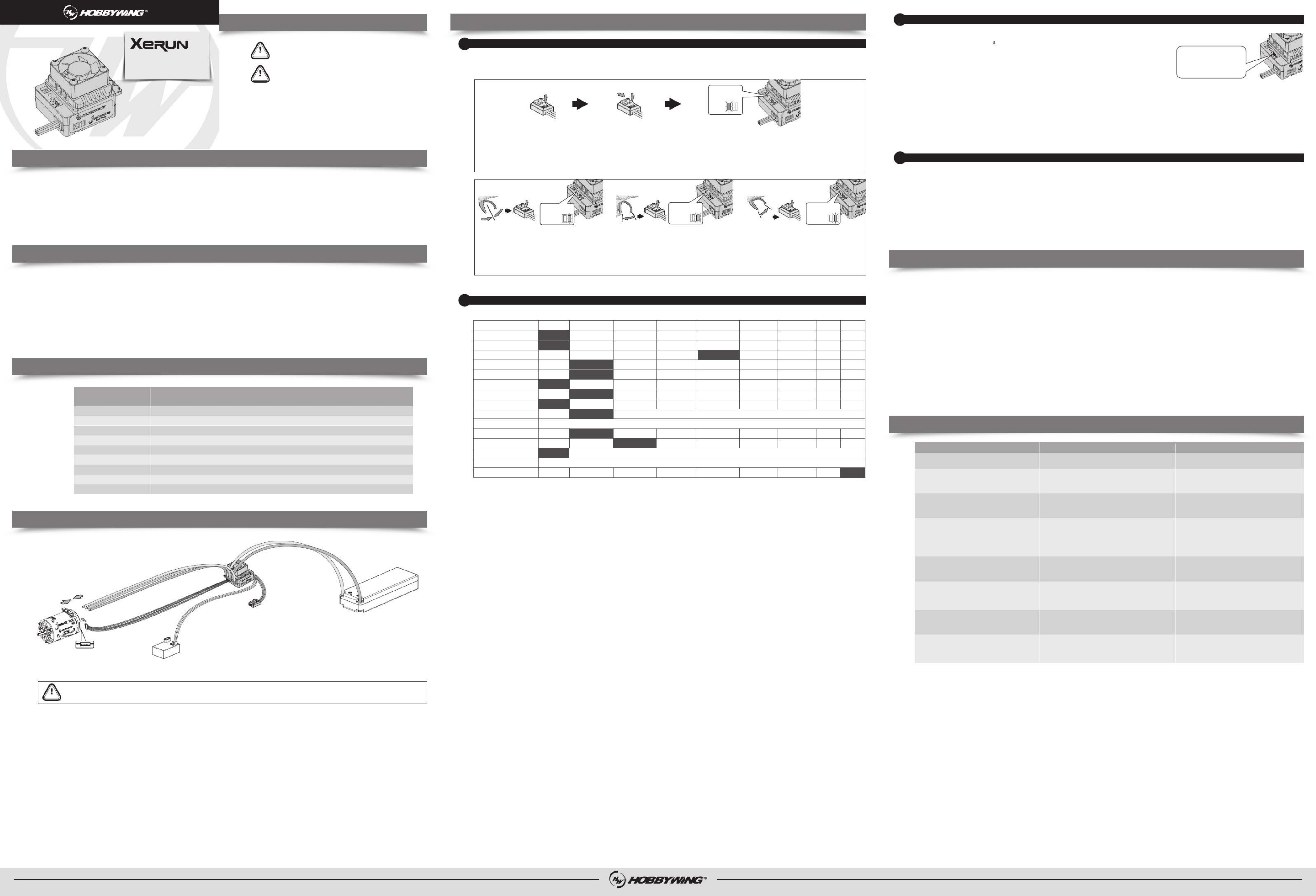
Please wire correctly according to wiring instructions and wiring diagram.
1. Motor Connection
The sensored motor wiring is a little different from the sensorless motor wiring; please make sure that you will strictly follow the introductions below.
A. Sensored Brushless Motor Connection
Sensored motors have a specific wiring order, the three A/B/C ESC wires must connect to the three A/B/C motor wires correspondingly,
otherwise, it may damage the ESC, and then connect the ESC sensor port and the motor sensor port with the stock 6-pin sensor cable.
Note: If the motor direction is reversed, change the parameter on item 8“Motor Rotation”to achieve the correct setting.
B. Sensorless Brushless Motor Connection
There are no wire sequencing requirements needed when using a sensorless brushless motor,you can swap two wires if the motor runs in opposite direction.
2. Receiver Connection
Plug the throttle control cable (also called Rx cable) on the ESC into the throttle (TH) channel on receiver. Please do not supply power to the receiver,your ESC will be damaged.
If additional power is required, disconnect the red wire on the throttle plug from the ESC.
3. Battery Connection
Connect the battery when the ESC is powered off. Make sure positive (+) of ESC connects to positive (+) of battery, and negative (-) of ESC connects to negative (-) of battery when you plug in
your battery! Then turn on the ESC to run it.
You must calibrate throttle range when you begin to use a new ESC, the transmitter has been replaced,or the Throttle TRIM have been adjusted, otherwise the ESC cannot work correctly.
We strongly recommend to activate the “Fail Safe” function of the transmitter and set no signal protection for throttle channel of transmitter (F/S) to “OFF” or set its value to the “Neutral
Position” to ensure the motor can be stopped when there is no signal received from the transmitter. The throttle calibration steps is as follows:
Programmable Items
2
Those "black background and white text" options are the factory default settings.
1. Running Mode
Option 1: Forward with Brake
The vehicle can go forward and brake but cannot reverse in this mode. This mode is usually for racing.
Option 2: Forward/Reverse with Brake
This option is known to be the “training” mode with “Forward/Reverse with Brake” function. The vehicle only brakes on the first time you push the throttle trigger to the reverse/brake
position. If the motor stops when the throttle trigger return to the neutral position and then re-push the trigger to reverse position, the vehicle will reverse, if the motor does not
completely stop, then your vehicle won’t reverse but still brake, you need to return the throttle trigger to the neutral position and push it to reverse again. This method is for preventing
vehicle from being accidentally reversed.
Option 3: Forward/Reverse
The motor will reverse immediately when the throttle trigger is pushed to reverse position. This mode is generally used in special vehicles.
2. Max. Reverse Force
Different reverse amount will bring different reversing speed. For the safety of your vehicle, we recommend using a low amount.
3. Cutoff Voltage (or Low Voltage Cutoff Threshold)
The ESC will monitor the battery voltage all the time, once the voltage is lower than the threshold value, the ESC will reduce the power to 50% and cutoff the power output in 40
seconds. When enters into voltage pr otection, the RED LED will single flash that repeats ( …….). Please set the “Cutoff Voltage” to “Disabled” if you are using NiMH batteries.☆, ☆, ☆, ☆
4. ESC Thermal Protection
The output from the ESC will be cut off with the value you have preset. The GREEN LED flashes ( ) when the ESC temperature reaches to the preset value. The output will not ☆, ☆, ☆....
resume until the ESC temperature gets down.
Warning! Please do not disable this function unless you’re in a competition. Otherwise the high temperature may damage your ESC and even your motor.
5. Motor Thermal Protection
After enable this function, the output will be automatically closed when the motor temperature reaches the preset value. The green light flashes until the temperature drops to restore the
output. When the motor is overheated, the green light will flash twice in cycle (☆☆ ☆☆ ☆☆, , ....).
Warning! Please do not disable this function unless you’re in a competition. Otherwise the high temperature may damage your motor and even your ESC. For non-Hobbywing
motor, the ESC may get this protection activated too early/late because of the different temperature sensor inside the motor. In this case, please disable this function and
monitor the motor temperature manually.
6. BEC Voltage
The BEC voltage can be adjusted at 6.0V and 7.4V. The normal steering servo is generally set at 6.0V, and the high-voltage steering servo can be set at 7.4v. Select the appropriate voltage
according to the steering servo used.
Note: Do not set the BEC voltage above the maximum operating voltage of the servo and receiver, as this may damage the servo/receiver or even the ESC.
7. Smart Fan
This esc has a fan control function. If this item is set to "Disabled", the fan will continue to run after the ESC is powered on; If this item is set to "Enabled", The fan will start running after
the internal temperature of the esc exceeds 50℃/122℉.
8. Motor Rotation
It is used to adjust the rotation direction of the motor (in CW or CCW), that is, when the forward throttle is given, and the rotation direction of the motor is reverse, it can be set to the
opposite direction.
9. Freewheeling
When this function is enabled, it will it will slow down faster when releasing the throttle, provide better handling on the curve,and less heat under the same conditions.
10. Start Mode / Punch
This item is used to control the throttle response. It can be adjustable from 1 to 15 (step: 1), the lower this value, the slower the response; the higher this value, the faster the response. A
suitable rate can help driver to control his vehicle properly during the starting-up process.
11. Throttle Neutral Range
As not all transmitters have the same stability at “neutral position”, please adjust this parameter as per your radios neutral range.
12. Initial Throttle Force
It also called as minimum throttle force. You can set it according to wheel tire and traction. If the ground is slippery, please set a small throttle force.
13. RPM Limit
It is used to set the max. RPM value of the motor. Set corresponding values according to competition rules.
Note: The RPM limit value here corresponds to a 2-pole motor. If a 4-pole motor (such as a Justock Handout motor) is used, it needs to be divided by 2 to obtain the corresponding
mechanical rpm value.For example, using a Justock Handout 13.5T (3200KV) motor, if you want to limit the rpm to 22000rpm (mechanical rpm), you need to set the RPM limit value
to: 22000*2=44000.
14. Drag Brake Force
Refers to the brake force generated by the motor when the throttle trigger returns to neutral position. (Attention! Drag brake will consume much power, so please apply it cautiously.)
15. Max. Brake Force
This ESC provides the proportional braking function; the braking effect is determined by the position of the throttle trigger. The max. brake force is produced when the throttle trigger is at the
brake bottom position. Please select the max. brake force parameter as per your car condition and your preference.
SHENZHEN HOBBYWING TECHNOLOGY Co., LTD. · 101-402 Building 4, Yasen Chuangxin Hi-tech Industrial Park, 8 Chengxin Road, Baolong Industrial Town, Longgang District, Shenzhen, China. January 31, 2024
ESC Programming
3
Plug the programming cable of OTA Programmer to the programming port of ESC. Then use the mobile phone to install
HOBBYWING HW LINK App to set parameters.
07
Explanations for Different Status LED
Factory Reset
4
1) Restore the default values with the SET button
Press and hold the SET button for over 3 seconds anytime when the throttle trigger is at the neutral position (except during the ESC calibration and programming) can factory reset your
ESC. RED & GREEN LEDs flash simultaneously indicating you have successfully restored all the default values within your ESC. Once you power the ESC off, and then back on, your settings
will be back in the default mode.
2) Restore the default values with a multifunction LCD program box pro
After connecting the program box to the ESC, Click on [Parameter Settings], and then click on "Reset parameter" at the bottom of the parameter items.
3) Restore the default values with a OTA Programmer(Use HW LINK mobile phone App)
Connect OTA Programmer to the ESC, enter into , click “reset” to factory reset your ESC.【Parameter】
1. The throttle is in neutral zone
1) In normal Blinky mode (non-rpm limit mode), the red LED flashes rapidly.
2) In the RPM limit mode, setting different RPM limit values results in different LED flashing phenomena, the specific rules are: the number of times the green light flashes represents ten
thousand digits of the RPM limit value you set, and the number of times the red light flashes represents one thousand digits of the RPM limit value you set.
For example, if the RPM limit is set to 25000, the green light will flash twice and then the red light will flash five times. This cycle; If the RPM limit is set to 40000, the green light will
flash four times and cycle. And so on.
2. The throttle is in non-neutral zone
1) The LED turns on solid when moving forward. Green LED is also on when throttle trigger is at the end position of forward 100% throttle on non-speed limit mode).RED ( ,
2) The RED LED turns on solid when you brake. The GREEN LED will also come on when pushing the throttle trigger to the full brake endpoint and setting the “Max. Brake Force” to 100%.
3) The RED LED turns on solid when you reverse your vehicle.
3. LED status when some Protection is Activated:
1) The RED LED flashes a short, single flash that repeats ( ) indicating the low voltage cutoff protection is activated.☆- ☆- ☆-, ,
2) The GREEN LED flashes a short, single flash that repeats ( ) indicating the ESC thermal / overheat protection is activated.☆- ☆- ☆-, ,
3) The GREEN LED flashes a short, double flash that repeats ( ) indicating the motor thermal /overheat protection is activated.☆-☆- ☆-☆- ☆-☆-, ,
4) The GREEN LED flashes a short, five times flash that repeats ( ) indicating the capacitor thermal /overheat protection is activated.☆-☆-☆-☆-☆- ☆-☆-☆-☆-☆-,
Trouble(s) Solution(s)Possible Causes
1. No power was supplied to the ESC.
2. The ESC switch was damaged.
1. Check if all ESC & battery connectors have been well
soldered or firmly connected.
2. Replace the broken switch.
The motor was unable to start and the LED is not on after
power on.
The throttle signal is not detected.
Check if the transmitter is turned on and bound, check if the
throttle wire is reversely plugged in or whether the receiver is
good (Insert the throttle wire to the channel of servo to debug)
ESC was unable to start the motor after it was powered on,
but the red LED flashes quickly.
1. The receiver was influenced by some foreign interference.
2. The ESC entered the LVC protection.
3. The ESC entered the thermal shutdown protection.
1. Check the cause of interference on the receiver, and check the
battery power of the transmitter.
2. The RED LED keeps flashing indicating the LVC protection is
activated, please replace your pack.
3. The GREEN LED keeps flashing indicating the thermal protection
is activated, please let your ESC cool down before using it again.
The motor suddenly stopped or significantly reduced the output
in operation.
1. The wire connections between the motor and ESC were not A-A,
B-B and C-C.
2. Some soldering between the motor and the ESC was not good.
3. The ESC was damaged (some MOSFETs were burnt).
1. Check the connections;
2. Check all soldering points, please re-solder if necessary.
3. Contact the distributor for repair.
The motor stuttered but couldn’t start.
1. The throttle neutral position on your transmitter was actually in the
braking zone.
2. Set the “Running Mode” improperly.
3. The ESC was damaged.
1. Re-calibrate the throttle neutral position. The LED on the ESC is
not on when the throttle trigger is at the neutral position.
2. Set the “running mode” to “Forward/Reverse with Brake”.
3. Contact the distributor for repair.
The vehicle could run forward (and brake), but could not reverse.
1. The neutral position on the transmitter was not stable, so signals
were not stable either.
2. The throttle range is not calibrated properly.
1. Replace a transmitter with stable signal.
2. Re-calibrate the throttle range or fine tune the neutral position
on the transmitter.
The car ran forward/backward slowly when the throttle trigger
was at the neutral position.
The ESC did not receive correct throttle signal.
Check if the transmitter is turned on and bound, check if the
throttle wire is reversely plugged in or plugged in wrong channel,
whether the receiver is damaged (Insert the throttle wire to the
channel of servo to debug)
The setting of throttle range cannot be completed.
The battery voltage was beyond the normal operating voltage range of
the ESC. Check the battery voltage.
The ESC was unable to start the motor after it was powered on,
but the motor emitted a short, double beep (BB, BB, BB...) that
repeats with GREEN LED on the ESC blinked. (The interval
between two beeps was 1 second.)
• Ensure all wires and connections are well insulated before connecting the ESC to related devices, as short circuit will damage your ESC.
• Ensure all devices in the system are connected correctly to prevent any damage to the system.
• Please carefully check power devices and manual of car frame to ensure the power pairing is reasonable. Avoid incorrect pairing to overload the motor and damage the ESC.
• Please use a soldering iron with the power of at least 50W to solder all input/output wires and connectors.
• Stop using the ESC when its outer temperature exceeds 90 ; otherwise your ESC will be damaged and may also damage your motor.℃/194℉
• The battery must be disconnected after use.There is a small draw even when the system is off,and will eventually fully drain the battery.This may cause damage to the ESC, and will NOT BE
COVERED UNDER WARRANTY.
Hold the SET
button.
Turn on the
switch
1. Turn on the transmitter, set parameters on the throttle channel like “D/R”, “EPA” and “ATL” to 100% (for transmitter without LCD, please turn the knob to the maximum) and the
throttle “TRIM” to 0 (for transmitter without LCD, please turn the corresponding knob to the neutral position). This step can be skipped if the radio's settings are default!
2. Turn off the ESC. Hold the SET button and turn on the ESC, the RED LED on the ESC starts to flash (the motor beeps at the same time), and then release the SET button.
Note : Beeps from the motor may be low sometimes, and you can check the LED status instead.
1. Program your ESC with a LCD program box pro
2. Program your ESC with a OTA Programmer
3. Data Logging
1) The ESC is able to record the Maximum Temperature of ESC and Motor, Minimum Battery Voltage, Maximum Motor RPM and Maximum Current in running. It automatically saves the
recorded data when you turn off the ESC after a run. You can check those data via a multifunction LCD program box pro. Users need to switch on the ESC after the esc is connected
with the program box.Click on [Data Record] to view the above five extreme value data.
2) The ESC running data is read through the OTA Bluetooth module. After connecting the OTA Bluetooth module to the esc and establishing communication, you can view not only the
five extreme value data recorded above, but also the real-time running data and historical record data (graph) in the [Data Log] menu in HW link app.
Connect LCD program box or
OTA module at this independent
programming port.
HW-SMA536DUL01-A1
USER MANUAL
XERUN XR10 Justock G3S
Brushless Electronic Speed Controller
03
Features
04
Specifications
05
Connections
08
Trouble Shooting
Press the SET button
and the Green LED
flashes once.
Option 1
1. Running Mode
2. Max. Reverse Force
3. Cutoff Voltage
4. ESC Thermal Protection
5. Motor Thermal Protection
6. BEC voltage
7. Smart Fan
8. Motor Rotation
9. Freewheeling
10. Start Mode (Punch)
11. Neutral Range
12. Initial Throttle Force
13. RPM Limit
14. Drag Brake Force
15. Max.Brake Force
Option 2 Option 3 Option 4 Option 5 Option 6 Option 7 Option 8 Option 9
Forward and Reverse
75%
2.8V/Cell
10%
25%
5%
50%
1-15 (Adjust Step:1)
10000RPM - 88000RPM (Adjust Step: 1000RPM)
0-100% (Adjust Step: 5%)
6%
62.5%
8%
75%
10%
87.5%
12%
3.4V/Cell
100%
3.0V/Cell
4%
37.5%
Programmable Items
Forward with
Brake
6.0V
25%
CCW
3%
3.2V/Cell
100%
Enabled
Enabled
Enabled
Enabled
8%
Unlimited
Disabled
Disabled
Disabled
Disabled
Disabled
6%
1%
0%
Forward/
Reverse with Brake
50%
2.6V/Cell
7.4V
CW
2%
12.5%
20240131
Connect the interface marked with "- + " on the esc to the interface marked with "ESC" on the program box using a
separate programming cable(a cable with JR plugs at both ends included in the program box packaging),then connect the
battery to the esc and turn it on. Click[Parameter Settings]to set the esc.
Release the SET
button once the
LED flashes.
Sensor port of motor
Battery
Switch
Electronic Speed Controller
Receiver
Motor
Sensor wire
C
A
B

Product specificaties
| Merk: | Hobbywing |
| Categorie: | Radiografisch bestuurbaar speelgoed |
| Model: | XeRun XR10 Justock G3S |
Heb je hulp nodig?
Als je hulp nodig hebt met Hobbywing XeRun XR10 Justock G3S stel dan hieronder een vraag en andere gebruikers zullen je antwoorden
Handleiding Radiografisch bestuurbaar speelgoed Hobbywing

29 Maart 2025
29 Maart 2025
27 Maart 2025
27 Maart 2025
27 Maart 2025
27 Maart 2025
27 Maart 2025
27 Maart 2025
27 Maart 2025
27 Maart 2025
Handleiding Radiografisch bestuurbaar speelgoed
- Radiografisch bestuurbaar speelgoed Absima
- Radiografisch bestuurbaar speelgoed ACME
- Radiografisch bestuurbaar speelgoed Amewi
- Radiografisch bestuurbaar speelgoed Blade
- Radiografisch bestuurbaar speelgoed DJI
- Radiografisch bestuurbaar speelgoed Futaba
- Radiografisch bestuurbaar speelgoed Graupner
- Radiografisch bestuurbaar speelgoed Little Tikes
- Radiografisch bestuurbaar speelgoed MJX
- Radiografisch bestuurbaar speelgoed Multiplex
- Radiografisch bestuurbaar speelgoed Parrot
- Radiografisch bestuurbaar speelgoed Proline
- Radiografisch bestuurbaar speelgoed Reely
- Radiografisch bestuurbaar speelgoed Revell
- Radiografisch bestuurbaar speelgoed Robbe
- Radiografisch bestuurbaar speelgoed SAB
- Radiografisch bestuurbaar speelgoed Sharper Image
- Radiografisch bestuurbaar speelgoed Spektrum
- Radiografisch bestuurbaar speelgoed TacTic
- Radiografisch bestuurbaar speelgoed Tamiya
- Radiografisch bestuurbaar speelgoed Velleman
- Radiografisch bestuurbaar speelgoed WLtoys
- Radiografisch bestuurbaar speelgoed JR
- Radiografisch bestuurbaar speelgoed Overmax
- Radiografisch bestuurbaar speelgoed Conrad
- Radiografisch bestuurbaar speelgoed Chicco
- Radiografisch bestuurbaar speelgoed Carrera
- Radiografisch bestuurbaar speelgoed Biltema
- Radiografisch bestuurbaar speelgoed Lenoxx
- Radiografisch bestuurbaar speelgoed Carson
- Radiografisch bestuurbaar speelgoed Ninco
- Radiografisch bestuurbaar speelgoed Traxxas
- Radiografisch bestuurbaar speelgoed ARRMA
- Radiografisch bestuurbaar speelgoed Spin Master
- Radiografisch bestuurbaar speelgoed ParkZone
- Radiografisch bestuurbaar speelgoed JETI
- Radiografisch bestuurbaar speelgoed SkyRC
- Radiografisch bestuurbaar speelgoed LRP
- Radiografisch bestuurbaar speelgoed Ripmax
- Radiografisch bestuurbaar speelgoed Maverick
- Radiografisch bestuurbaar speelgoed Axial
- Radiografisch bestuurbaar speelgoed Hangar 9
- Radiografisch bestuurbaar speelgoed FMS
- Radiografisch bestuurbaar speelgoed E-flite
- Radiografisch bestuurbaar speelgoed Flyzone
- Radiografisch bestuurbaar speelgoed Losi
- Radiografisch bestuurbaar speelgoed XciteRC
- Radiografisch bestuurbaar speelgoed FrSky
- Radiografisch bestuurbaar speelgoed Force Engine
- Radiografisch bestuurbaar speelgoed Vaterra
- Radiografisch bestuurbaar speelgoed Jada
- Radiografisch bestuurbaar speelgoed HPI Racing
- Radiografisch bestuurbaar speelgoed Kyosho
- Radiografisch bestuurbaar speelgoed PowerBox Systems
- Radiografisch bestuurbaar speelgoed Hobby Zone
- Radiografisch bestuurbaar speelgoed RC4WD
- Radiografisch bestuurbaar speelgoed Sky Rider
- Radiografisch bestuurbaar speelgoed DF-Models
- Radiografisch bestuurbaar speelgoed ROCHOBBY
Nieuwste handleidingen voor Radiografisch bestuurbaar speelgoed
31 Maart 2025
30 Maart 2025
30 Maart 2025
29 Maart 2025
29 Maart 2025
29 Maart 2025
29 Maart 2025
29 Maart 2025
29 Maart 2025
29 Maart 2025