Hikvision DS-KP8200-HE1 Handleiding
Hikvision
Intercomsysteem
DS-KP8200-HE1
Lees hieronder de 📖 handleiding in het Nederlandse voor Hikvision DS-KP8200-HE1 (122 pagina's) in de categorie Intercomsysteem. Deze handleiding was nuttig voor 36 personen en werd door 2 gebruikers gemiddeld met 4.5 sterren beoordeeld
Pagina 1/122

DS-KP8200-HE1
User Manual

3 / 122
Directory
Directory ............................................................................................................................................................................. 3
1 Picture .............................................................................................................................................................................. 8
2 Table ............................................................................................................................................................................... 12
3 Safety Instruction........................................................................................................................................................ 13
4 Overview ....................................................................................................................................................................... 14
4.1 Overview ........................................................................................................................................................... 14
4.2 Packing Contents ................................................................................................................................................ 14
5 Desktop Installation ................................................................................................................................................... 16
5.1 PoE and the use of external power adapters .............................................................................................. 16
5.2 Desktop and wall mounted method ..................................................................................................................... 17
6 Appendix Table............................................................................................................................................................ 19
6.1 Appendix I - Icon .............................................................................................................................................. 19
6.2 Appendix - Keyboard character query tableII ............................................................................................. 22
Appendix LED DenitionIII – ................................................................................................................................ 24
7 Introduction to the User ............................................................................................................................................ 25
7.1.1 Instruction of Keypad ............................................................................................................................. 25
7.2 Using Handset / Hands-free Speaker / Headphone ................................................................................... 25
7.3 Idle Screen ....................................................................................................................................................... 27
7.4 Phone Status .................................................................................................................................................... 28
7.5 Web Management ........................................................................................................................................... 29
7.6 Network Congurations .................................................................................................................................. 30
7.7 SIP Congurations .......................................................................................................................................... 30
8 Basic Function ............................................................................................................................................................. 32
8.1 Making Phone Calls ........................................................................................................................................ 32
8.2 Answering Calls ............................................................................................................................................... 33
8.2.1 Talking ...................................................................................................................................................... 34
8.2.2 Make / Receive Second Call ................................................................................................................. 34
8.3 End of the Call ................................................................................................................................................. 35
8.4 Redial ................................................................................................................................................................ 36
8.5 Dial-up Query ................................................................................................................................................... 36
8.6 Auto-Answering ............................................................................................................................................... 36
8.7 Callback ............................................................................................................................................................ 37
8.8 Mute ................................................................................................................................................................... 38
8.8.1 Mute the Call ........................................................................................................................................... 38

4 / 122
8.8.2 Ringing Mute ........................................................................................................................................... 39
8.9 Call Hold/Resume............................................................................................................................................ 39
8.10 DND ................................................................................................................................................................. 40
8.11 Call Forward ................................................................................................................................................... 41
8.12 Call Transfer ................................................................................................................................................... 43
8.12.1 Blind transfer ......................................................................................................................................... 43
8.12.2 Semi-Attended transfer ....................................................................................................................... 43
8.12.3 Attended transfer .................................................................................................................................. 44
8.13 Call Waiting .................................................................................................................................................... 44
8.14 Conference ..................................................................................................................................................... 45
8.14.1 Local Conference ................................................................................................................................. 45
8.14.2 Network Conference ............................................................................................................................ 46
8.15 Call Park ......................................................................................................................................................... 47
8.16 Pick Up ............................................................................................................................................................ 48
8.17 Anonymous Call ............................................................................................................................................ 49
8.17.1 Anonymous Call ................................................................................................................................... 49
8.17.2 Ban Anonymous Call ........................................................................................................................... 50
8.18 Hotline ............................................................................................................................................................. 50
8.19 Emergency Call ............................................................................................................................................. 51
9 Advance Function ....................................................................................................................................................... 53
9.1 BLF (Busy Lamp Field) ................................................................................................................................... 53
9.1.1 Configure the BLF Functionality ........................................................................................................... 53
9.1.2 Use the BLF Function ............................................................................................................................ 54
9.2 BLF List ............................................................................................................................................................. 54
9.3 Record ............................................................................................................................................................... 55
9.3.1 Local Record ............................................................................................................................................. 55
9.3.2 Server Record ......................................................................................................................................... 56
9.3.3 SIP INFO Record .................................................................................................................................... 57
9.4 Agent ................................................................................................................................................................. 57
9.5 Intercom ............................................................................................................................................................ 59
9.6 MCAST .............................................................................................................................................................. 59
9.7 SCA Shared Call Appearance ( ) .................................................................................................................... 60
9.8 Message ........................................................................................................................................................... 63
9.8.1 SMS .......................................................................................................................................................... 63
9.8.2 MWI (Message Waiting Indicator) ........................................................................................................ 64
9.9 SIP Hotspot ...................................................................................................................................................... 65
10 Phone Settings .......................................................................................................................................................... 68
10.1 Basic Settings ................................................................................................................................................ 68

5 / 122
10.1.1 Language ............................................................................................................................................... 68
10.1.2 Time & Date .......................................................................................................................................... 68
10.1.3 Screen .................................................................................................................................................... 70
10.1.3.1 Brightness and backlight .......................................................................................................... 70
10.1.3.2 Screen Saver ............................................................................................................................. 71
10.1.4 Ring ........................................................................................................................................................ 71
10.1.5 Voice Volume ........................................................................................................................................ 71
10.1.6 Greeting Words..................................................................................................................................... 72
10.1.7 Reboot.................................................................................................................................................... 72
10.2 Phone Book .................................................................................................................................................... 72
10.2.1 Local Contact ........................................................................................................................................ 72
10.2.1.1 Add / Edit / Delete Contact ...................................................................................................... 73
10.2.1.2 Add / Edit / Delete Group ......................................................................................................... 73
10.2.1.3 Browse and Add / Remove Contacts in Group ..................................................................... 74
10.2.2 Blacklist .................................................................................................................................................. 74
10.2.3 Cloud Phone Book ............................................................................................................................... 75
10.2.3.1 Congure Cloud Phone book .................................................................................................. 75
10.2.3.2 Downloading Cloud Phone book ............................................................................................ 76
10.3 Call Log ........................................................................................................................................................... 76
10.4 Function Key .................................................................................................................................................. 77
10.5 Wi-Fi ................................................................................................................................................................ 79
10.6 Headset........................................................................................................................................................... 79
10.6.1 Wired Headset ...................................................................................................................................... 79
10.6.2 EHS Headset ........................................................................................................................................ 79
10.6.3 Bluetooth Headset ................................................................................................................................ 80
10.7 Advanced ........................................................................................................................................................ 81
10.7.1 Line Congurations .............................................................................................................................. 81
10.7.2 Network Settings .................................................................................................................................. 81
10.7.2.1 Network Settings ....................................................................................................................... 81
10.7.2.2 QoS & VLAN .............................................................................................................................. 83
10.7.2.3 VPN ............................................................................................................................................. 84
10.7.2.4 Web Server Type ...................................................................................................................... 85
10.7.3 Set The Secret Key .............................................................................................................................. 85
10.7.4 Maintenance .......................................................................................................................................... 86
10.7.5 Firmware Upgrade ............................................................................................................................... 89
10.7.6 Factory Reset ........................................................................................................................................ 91
11 Web Congurations ................................................................................................................................................. 92
11.1 Web Page Authentication ............................................................................................................................ 92

6 / 122
11.2 System Information>> ................................................................................................................................. 92
11.3 System Account>> ....................................................................................................................................... 92
11.4 System Congurations>> ............................................................................................................................ 92
11.5 System Upgrade>> ...................................................................................................................................... 93
11.6 System Auto Provision>> ............................................................................................................................ 93
11.7 System Tools>> ............................................................................................................................................ 93
11.8 System Reboot Phone>> ............................................................................................................................ 93
12 Network Basic>> ...................................................................................................................................................... 94
12.1 Network >> Wi- SettingsFi ............................................................................................................................. 94
12.2 Network Service Port>> .............................................................................................................................. 95
12.3 Network >> VPN ............................................................................................................................................ 95
12.4 Network vanced>> Ad .................................................................................................................................. 95
12.5 Line SIP>> ..................................................................................................................................................... 96
12.6 Line >> SIP Hotspot .................................................................................................................................... 101
12.7 Line Dial Plan>> ......................................................................................................................................... 101
12.8 Line Action Plan>> ..................................................................................................................................... 103
12.9 Line Basic Settings>> ................................................................................................................................ 104
12.10 Line >> RTCP-XR ..................................................................................................................................... 104
12.11 Phone settings Features>> .................................................................................................................... 105
12.12 Phone settings Media Settings>> .......................................................................................................... 108
12.13 Phone settings MCAST>> ...................................................................................................................... 109
12.14 Phone settings Action>> ......................................................................................................................... 110
12.15 Phone settings Time/Date>> .................................................................................................................. 110
12.16 Phone settings Tone>> ........................................................................................................................... 111
12.17 Phone settings Advanced>> .................................................................................................................. 111
12.18 Phonebook Contact>> ............................................................................................................................ 112
12.19 Phonebook Cloud phonebook>> ........................................................................................................... 112
12.20 Phonebook Call List>> ............................................................................................................................ 113
12.21 Phonebook >> Web Dial .......................................................................................................................... 114
12.22 Phonebook Advanced>> ........................................................................................................................ 114
12.23 Call Log ....................................................................................................................................................... 114
12.24 Function Key Side Key>> ....................................................................................................................... 114
12.25 Function Key Softkey>> .......................................................................................................................... 115
12.26 Function Key >> Advanced ..................................................................................................................... 116
12.27 Application >> Manage Recording ......................................................................................................... 116
12.28 Security Web Filter>> .............................................................................................................................. 116
12.29 Security Trust Certicates>> .................................................................................................................. 117
12.30 Security Device Certicates>> ............................................................................................................... 118

7 / 122
12.31 Security Firewall>> .................................................................................................................................. 119
12.32 Device Log Device Log>> ...................................................................................................................... 120
13 Trouble Shooting .................................................................................................................................................... 121
13.1 Get Device System Information ................................................................................................................ 121
13.2 Reboot Device ............................................................................................................................................. 121
13.3 Reset Device to Factory Default ............................................................................................................... 121
13.4 Screenshot ................................................................................................................................................... 121
13.5 Network Packets Capture .......................................................................................................................... 122
13.6 Get Log Information .................................................................................................................................... 122
13.7 Common Trouble Cases ............................................................................................................................ 122

8 / 122
1 Picture
Picture - Device installation1 ....................................................................................................................... 17
Picture - Wall-mounted installation2 .......................................................................................................... 17
Picture - Connecting to the Device3 .......................................................................................................... 18
Picture 4 - Instruction of Keypad of J6 ......................................................................................................... 25
Picture - Screen layout/default home screen5 ......................................................................................... 27
Picture - Scroll icon6 .................................................................................................................................... 28
Picture - The Phone status7 ........................................................................................................................ 28
Picture - WEB phone status8 ...................................................................................................................... 29
Picture - Landing page9 ............................................................................................................................... 29
Picture - Phone line SIP address and account information10 ................................................................ 31
Picture 11 - Web SIP registration ................................................................................................................ 31
Picture - Default line12 ................................................................................................................................. 32
Picture - Enable voice channel dialing13 .................................................................................................. 33
Picture - Open the voice channel and dial the number14 ....................................................................... 33
Picture - Call number15 ............................................................................................................................... 33
Picture - Answering calls16 ......................................................................................................................... 33
Picture - Talking interface17 ........................................................................................................................ 34
Picture - The second call interface18 ......................................................................................................... 35
Picture - Two way calling19 ......................................................................................................................... 35
Picture - Redial set20 ................................................................................................................................... 36
Picture - Line 1 enables auto-answering21 .............................................................................................. 37
Picture - The line has enabled auto-answering22 .................................................................................... 37
Picture - Web page to start auto-answering23 ......................................................................................... 37
Picture - Set the callback key on the phone24 ......................................................................................... 38
Picture - Set the callback key on the web page25 ................................................................................... 38
Picture - Mute the call26 .............................................................................................................................. 39
Picture - Ringing mute27 ............................................................................................................................. 39
Picture - Call hold interface28 ..................................................................................................................... 40
Picture - Enable DND29 ............................................................................................................................... 40
Picture - DND setting interface30 ............................................................................................................... 40
Picture - DND timer31 .................................................................................................................................. 41
Picture - DND Settings32 ............................................................................................................................. 41
Picture - Line DND33 ................................................................................................................................... 41
Picture - Select the line to set up call forwarding34 ................................................................................. 42
Picture - Select call forward type35 ............................................................................................................ 42
Picture - Enable call forwarding and congure the call forwarding number36 .................................... 42

9 / 122
Picture - Set call forward37 ......................................................................................................................... 43
Picture - Transfer interface38 ...................................................................................................................... 43
Picture - Semi-Attended transfer39 ............................................................................................................ 44
Picture - Attended transfer40 ...................................................................................................................... 44
Picture - Call waiting setting41 ................................................................................................................... 45
Picture - Web call waiting setting42 ........................................................................................................... 45
Picture - Web call waiting tone setting43 .................................................................................................. 45
Picture - Local conference setting44 .......................................................................................................... 46
Picture - Local conference (1)45 ................................................................................................................ 46
Picture - Local conference (2)46 ................................................................................................................ 46
Picture - Network conference47 ................................................................................................................. 47
Picture - Phone set call park48 ................................................................................................................... 47
Picture - WEB set call park49 ..................................................................................................................... 48
Picture - Phone pick up setting50 ............................................................................................................... 48
Picture - WEB pick up setting51 ................................................................................................................. 49
Picture - Enable anonymous call52 ............................................................................................................ 49
Picture - Enable Anonymous web page call53 ......................................................................................... 49
Picture - Anonymous call log54 .................................................................................................................. 50
Picture - Anonymous calls are not allowed on the phone55 .................................................................. 50
Picture - Page Settings blocking anonymous call56 ............................................................................... 50
Picture - Phone hotline setting interface57 ............................................................................................... 51
Picture - Hotline set up on webpage58 ...................................................................................................... 51
Picture - Set up an emergency call number59 ......................................................................................... 52
Picture - Dial the emergency number60 .................................................................................................... 52
Picture - Web page conguration BLF function key61 ............................................................................ 53
Picture - Phone conguration BLF function key62 ................................................................................... 53
Picture - Congure the BLF List functionality63 ....................................................................................... 55
Picture - BLF List number display64 .......................................................................................................... 55
Picture 65 - WEB local recording .................................................................................................................... 56
Picture 66 - Web server recording .................................................................................................................... 57
Picture - Web SIP info recording67 ............................................................................................................ 57
Picture - Congure the agent account in normal mode68 ...................................................................... 58
Picture - Congure the proxy account-hotel Guest mode69 .................................................................. 58
Picture - Agent logon page70 ...................................................................................................................... 59
Picture - Web Intercom congure71 ........................................................................................................... 59
Picture - Multicast Settings Page72 ........................................................................................................... 60
Picture - Register BroadSoft account73 .................................................................................................... 61
Picture - Set BroadSoft server74 ................................................................................................................ 61

/ 12210
Picture - Enable SCA75 ............................................................................................................................... 62
Picture - Set Private Hold Function Key76 ................................................................................................ 62
Picture - SMS icon77 .................................................................................................................................... 64
Picture - New Voice Message Notication78 ............................................................................................ 64
Picture - Voice message interface79 ......................................................................................................... 65
Picture - Congure voicemail number80 ................................................................................................... 65
Picture - Register SIP account81 ............................................................................................................... 66
Picture - SIP hotspot server conguration82 ............................................................................................ 67
Picture - SIP hotspot client conguration83 .............................................................................................. 67
Picture - Phone language setting84 ........................................................................................................... 68
Picture - Language setting on Web page85 ............................................................................................. 68
Picture - Set time & date on phone86 ........................................................................................................ 69
Picture - Set time & date on webpage87 ................................................................................................... 69
Picture - Set screen parameters on phone88 ........................................................................................... 70
Picture - Page screen Settings89 ............................................................................................................... 71
Picture - Phone screen saver90 ................................................................................................................. 71
Picture - Phone book screen91 .................................................................................................................. 72
Picture - Local Phone book 92 ................................................................................................................... 73
Picture - Add New Contact93 ...................................................................................................................... 73
Picture - Group List94 .................................................................................................................................. 74
Picture - Browsing Contacts in a Group95 ................................................................................................ 74
Picture - Add Contacts in a Group96 ......................................................................................................... 74
Picture - Add Blacklist97 .............................................................................................................................. 75
Picture - Web Blacklist98 ............................................................................................................................. 75
Picture - Cloud phone book list99 .............................................................................................................. 76
Picture - Downloading Cloud Phone book100 .......................................................................................... 76
Picture - Browsing Contacts in Cloud Phone book101 ............................................................................ 76
Picture - Call Log102 .................................................................................................................................... 77
Picture - Filter call record types103 ............................................................................................................ 77
Picture - DSS LCD key Page Conguration Screen104 ......................................................................... 78
Picture - DSS settings105 ............................................................................................................................ 78
Picture 106 - Headset function settings ............................................................................................................ 79
Picture - EHS Headset setting107 .............................................................................................................. 80
Picture 108 - SIP address and account information .......................................................................................... 81
Picture - Congure Advanced Line Options109 ....................................................................................... 81
Picture 110 - twork mode SettingsNe .......................................................................................................... 81
Picture 111 - DHCP network mode .............................................................................................................. 82
Picture 112 - PPPoE network mode ............................................................................................................ 82

/ 12211
Picture 113 - Static IP network mode .......................................................................................................... 82
Picture 114 - IPv6 Static IP network mode ................................................................................................. 83
Picture 115 - The phone congures the web server type ......................................................................... 85
Picture 116 - Keypad lock password ........................................................................................................... 85
Picture 117 - Set keyboard lock password ............................................................................................... 86
Picture 118 - Phone keypad lock password input interface ..................................................................... 86
Picture 119 - Web keyboard lock password Settings ............................................................................... 86
Picture - Page auto provision Settings120 ................................................................................................ 87
Picture - Phone auto provision settings121 .............................................................................................. 87
Picture - Web page rmware upgrade122 ................................................................................................. 89
Picture - Firmware upgrade information display123 ................................................................................ 90
Picture 124 - Network Priority ......................................................................................................................... 94
Picture 125 - WiFi Settings .............................................................................................................................. 94
Picture - Service Port Settings126 .............................................................................................................. 95
Picture - Dial plan settings127 .................................................................................................................. 101
Picture - Custom setting of dial - up rules128 ......................................................................................... 102
Picture - Dial rules table (1)129 ................................................................................................................ 103
Picture - Dial rules table (2)130 ................................................................................................................ 103
Picture - Tone settings on the web131 ..................................................................................................... 111
Picture - Web cloud phone book Settings132 ......................................................................................... 113
Picture - Global Key Settings133 .............................................................................................................. 116
Picture - Web Filter settings134 ................................................................................................................ 117
Picture - Web Filter Table135 .................................................................................................................... 117
Picture - Certificate of settings136 ............................................................................................................ 118
Picture - Device certicate setting137 ...................................................................................................... 118
Picture - Network rewall Settings138 ..................................................................................................... 119
Picture - Firewall Input rule table139 ........................................................................................................ 120
Picture - Delete rewall rules140 .............................................................................................................. 120
Picture - Screenshot141 ............................................................................................................................. 122
Picture - Web capture142 .......................................................................................................................... 122

/ 12212
2 Table
Table - Hardware Interface Description1 ................................................................................................... 18
Table - Keypad Icons2 ................................................................................................................................. 19
Table - Status Prompt and Notication Icons3 ......................................................................................... 19
Table - DSSKEY Icon4 ................................................................................................................................. 21
Table - Look-up Table of Characters5 ........................................................................................................ 22
Table - DSS KEY LED State6 ..................................................................................................................... 24
Table 7 - Instruction of Keypad of J6 ............................................................................................................. 25
Table - Talking mode8 .................................................................................................................................. 34
Table - BLF Function key subtype parameter list9 .................................................................................. 53
Table - Agency mode10 ............................................................................................................................... 58
Table 11 - Intercom congure ....................................................................................................................... 59
Table - MCAST Parameters on Web12 ..................................................................................................... 60
Table - LED Status of SCA13 ...................................................................................................................... 62
Table - SIP hotspot Parameters14 ............................................................................................................. 66
Table - Time Settings Parameters15 .......................................................................................................... 69
Table - QoS & VLAN16 ................................................................................................................................ 83
Table - Auto Provision17 .............................................................................................................................. 87
Table - Firmware upgrade18 ....................................................................................................................... 90
Table - Service port19 .................................................................................................................................. 95
Table - Line conguration on the web page20 .......................................................................................... 96
Table - Phone 7 dialing methods21 .......................................................................................................... 101
Table - Dial - up rule conguration table22 ............................................................................................. 102
Table - IP camera23 ................................................................................................................................... 103
Table - Set the line global conguration on the web page24 ................................................................ 104
Table - VQ RTCP-XR Settings25 .............................................................................................................. 104
Table - General function Settings26 ......................................................................................................... 105
Table - Voice settings27 ............................................................................................................................. 108
Table - Multicast parameters28 ................................................................................................................. 110
Table - Time&Date settings29 ................................................................................................................... 110
Table - Function Key conguration30 ...................................................................................................... 114
Table - Softkey conguration31 ................................................................................................................ 115
Table - Network Firewall32 ........................................................................................................................ 119
Table - Trouble Cases33 ............................................................................................................................ 122

/ 12213
3 Safety Instruction
Please read the following safety notices before installing or using this unit. They are crucial for the safe and
reliable operation of the device.
Please use the external power supply that is included in the package. Other power supply may cause
damage to the phone and aect the behavior or induce noise.
Before using the external power supply in the package, please check the home power voltage.
Inaccurate power voltage may cause fire and damage.
Please do not damage the power cord. If power cord or plug is impaired, do not use it because it may
cause re or electric shock.
Do not drop, knock or shake the phone. Rough handling can break internal circuit boards.
This phone is design for indoor use. Do not install the device in places where there is direct sunlight. ed
Also do not put the device on carpets or cushions. It may cause re or breakdown.
Avoid exposure the phone to high temperature or below 0 or high humidity. ℃
Avoid wetting the unit with any liquid.
Do not attempt to open it. Non-expert handling of the device could damage it. Consult your authorized
dealer for help, or else it may cause re, electric shock and breakdown.
Do not use harsh chemicals, cleaning solvents, or strong detergents to clean it. Wipe it with a soft cloth
that has been slightly dampened in a mild soap and water solution.
When lightning, do not touch power plug, it may cause an electric shock.
Do not install this phone in an ill-ventilated place. You are in a situation that could cause bodily injury.
Before you work on any equipment, be aware of the hazards involved with electrical circuitry and be
familiar with standard practices for preventing accidents.

/ 12214
4 Overview
4.1 Overview
J6 Phone include high-end enterprise DSS intelligent display color screen phone, which greatly improve
enterprise production efciency with advanced design, high cost performance, paperless ofce tool. It is not
only a desktop phone, but also an elegant article that puts in the sitting room or oce.
The device is the latest generation of IP phone developed on the basis of the X series, inheriting many
excellent features of the previous X series traditional phone, such as high-denition voice, headphones and
high-performance echo cancellation full duplex speaker, fast / gigabit Ethernet, QoS, encryption transmission,
automatic conguration ew system, smooth operation, at interface settings and many other advantages. , n
For enterprise users, the equipment a cost-effective oce equipment, while realizing environmental is
protection, they also provide convenient operation Users can exibly congure and dene the functions of .
two DSS keys, space saving and cost. It will be an ideal choice for enterprise users and family users who
pursue the high quality and high efciency.
In order to help some interested users better understand the details of the product, this user manual can be
used as a reference guide for the use of XU series. This document may not be applicable to the latest version
of the software. If you have any questions, you can use the help prompt interface of the device phone, or
download and update your user manual from the ofcial website.
4.2 Packing Contents
P Handset hone

/ 12215
Receiver cable Stand Network cable
Power adapter (Optional) Hanging bracke (Need another purchase)

/ 12216
5 Desktop Installation
5.1 PoE and the use of external power adapters
The devices support two power supply modes from external power adapter or over Ethernet (PoE) complied
switch.
PoE power supply saves the space and cost of providing the device additional power outlet. With a PoE
switch, the device can be powered through a single Ethernet cable which is also used for data transmission.
By attaching UPS system to PoE switch, the device can keep working at power outage just like traditional
PSTN telephone which is powered by the telephone line.
For users who do not have PoE equipment, the traditional power adaptor should be used. If the device is
connected to a PoE switch and power adapter at the same time, the power adapter will be used in priority and
will switch to PoE power supply once it fails.
Please use the power adapter supplied and the PoE switch met the specications to ensure the device to
work properly.

/ 12217
5.2 Desktop and wall mounted method
The device supports two installation modes, desktop and wall mounted.If the phone is on the desktop, please
follow the instructions in the picture below to install the phone.
Picture 1 - Device installation
If the phone is mounted on the wall, please follow the instructions below to install it.
Picture 2 - Wall-mounted installation
Connect the power adapter, network, PC, phone and earphone to the appropriate port as shown in the picture
below.

/ 12218
Picture 3 - Connecting to the Device
Table 1 - Hardware Interface Description
Index
Interface
Description
Note
①
USB Port
Connect USB device (USB ash disk,
WiFi dongle, BT dongle)
②
Power Port
Connecting Power Adapter
③
Network Port
Connecting to LAN or Internet
④
PC Port
Network Interface for Connecting Computer
⑤
Headset Port
Connecting Headset
⑥
Receiver Port
Connecting Microphone Receiver

/ 12219
6 Appendix Table
6.1 Appendix I - Icon
Table 2 - Keypad Icons
Icon
Description
Redial
Call Log
Hands-free (HF) speaker
Mute Microphone (During Call)
Volume down
Volume up
Hold
Headset
MWI
Transfer
Conference
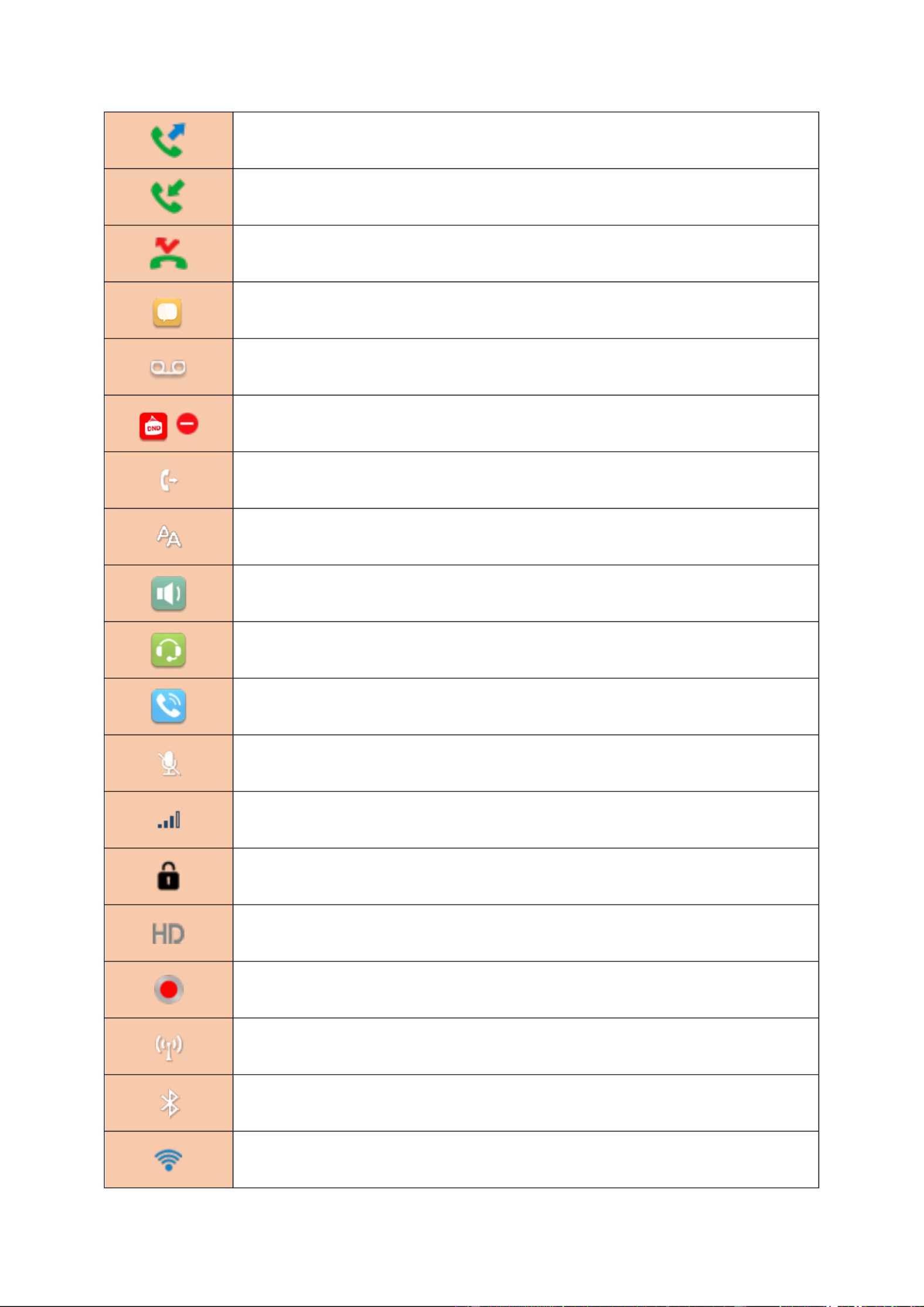
Table 3 - Status Prompt and Notication Icons
Screen Icon
Description
Call out
Call in
Call Hold
Network Disconnected
Open VLAN
Open VPN
Keypad Locked
Call forward calls
/ 12220
Outgoing calls
Incoming calls
Missed calls
SMS
New voice message waiting
Do-Not-Disturb activated on Phone in
Call forward activated
Auto-answering activated
Hands-free (HF) Mode
Headphone (HP) Mode
Handset (HS) Mode
Mute Microphone
The Voice quality of calling
The Voice encryption of calling
Speech High Denition
Record
SIP Hotspot
Bluetooth
Wi- Fi

/ 12221
USB Insert
USB overload
Table 4 - DSSKEY Icon
DSSKEY Icon
Side key Icon
Description
BLF/New call
BLF/XFER
BLF/AXFER
BLF/Conference
BLF/DTMF
Presence
Voice Message
Speed Dial
Intercom
Call Park
Call Forward
Keyevent
URI
BLF List
MCAST Paging

/ 12222
None for Memory Key
None for DSSKEY
Line Key
DTMF
6.2 Appendix - Keyboard character query table II
Table 5 - Look-up Table of Characters
Mode Icon
Text Mode
Key Button
Characters Each Press Of
Numeric
1
1
2
2
3
3
4
4
5
5
6
6
7
7
8
8
9
9
0
0
*
*.+
#
#
Lower Case
Alphabets
1
@:;()<>
2
a b c
3
d e f
4
g h i
5
j k l
6
m n o
7
p q r s
8
t u v
9
w x y z
0
(space)
*
.,*/+-:_=

/ 12223
#
# ^!&$%
Upper Case
Alphabets
1
@:;()<>
2
A B C
3
D E F
4
G H I
5
J K L
6
M N O
7
P Q R S
8
T U V
9
WZYX
0
(space)
*
.,*/+-:_=
#
# ^!&$%
Mixed type input
1
1
2
2 a b c A B C
3
3 d e f D E F
4
4 g h I G H I
5
5 j k l J K L
6
6 m n o M N O
7
7 p q r s P Q R S
8
8 t u v T U V
9
9 w z y x W Z Y X
0
0
*
.,*/+-:_=
#
# ^!&$%

/ 12224
Appendix LED Denition III –
Table 6 - DSS KEY LED State
Type
LED Light
State
Line Key
O
Line inactive
Green On
Line ready (Registered)
Green Blinking
Ringing
Red Blinking
Line is trying to register
Red Blinking
Line error (Registration failure)
Red On
Dialing/Line in use (Talking)
Yellow Blinking
Call holding
BLF
Green On
Subscription number is idle.
Red On
Subscription number is busy.
Red On
Subscription number is dialing.
O
Subscription number is unavailable.
Presence
Green On
Subscription number is idle.
Red On
Subscription number is busy.
Red On
Subscription number is dialing.
O
Subscription number is unavailable.
DND
Red On
Enable DND
O
Disable DND
MWI
Green Blinking
New voice message waiting
O
No new voice message
/ 12225
7 Introduction to the User
7.1.1 Instruction of Keypad
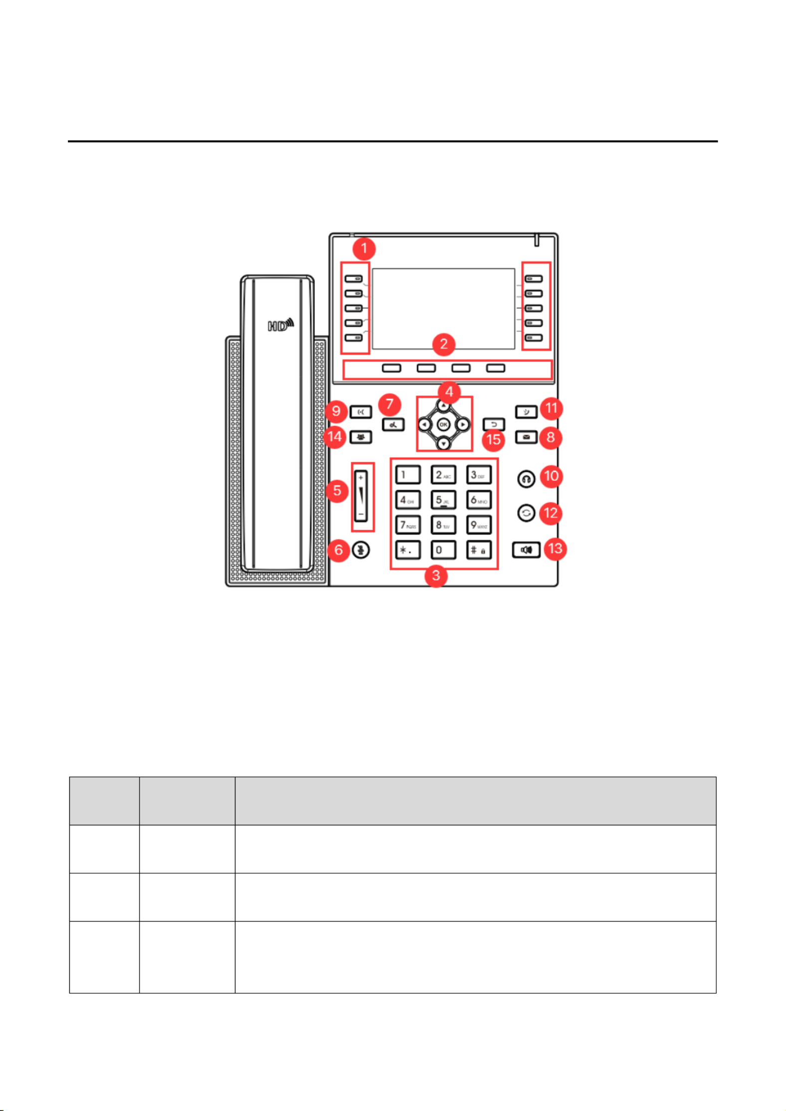
Picture 4 - Instruction of Keypad of J6
Table 7 - Instruction of Keypad of J6
7.2 Using
Number
The keypad
names
Instruction
○
1
Side Key
Long press the side key to enter the settings interface and set the required
functions.
○
2
Soft-menu
Buttons
These four buttons provide different functions corresponding to the
soft-menu displayed on the screen.
○
3
Standard
Telephone
Keys
The 12 standard telephone keys provide the same function as standard
telephones, but further to the standard function, some keys also provide
special function by long-pressing the key,

/ 12226
Key # - Long-pressed to lock the phone.
○
4
Navigate/OK
Keys
The user can press the up/down navigation key to change the line or move
the cursor in the screen list. On some Settings and text editing pages, the
user can press the left/right navigation key to change options or move the
cursor in the screen list to the left/right.
OK key: Default is equivalent to soft button confirmation; user can customize
the function.
○
5
Volume
Down/Volum
e Up Key
On the interface of ringing and ringing configuration in standby state, press
this button to increase or decrease the volume of ringing;Press this button to
increase or decrease the volume on the call or light adjustment interface.
○
6
Mute Key
During a call, the user can press this key to mute the microphone.
○
7
Hold Key
Press the "Hold" key during the call, the user can hold the call, and press it
again to cancel the holding and restore the normal call state.
○
8
Voice Mail
Press the "voice mail" button, and the user enters the interface of SMS and
voice mail list.
○
9
Transfer Key
Press the "Transfer" button, the user can transfer the current call to other
numbers.
○
10
Headset Key
Users can press this key to open the headset channel
○
11
Call Log Key
Press the "Call Log" key, the user can enter the Call Log interface and view
the call log.
○
12
Redial
Press the Redial key to redial the last number dialed
○
13
Hands-free
Key
The user can press this key to open the audio channel of the speakerphone.
○
14
Conference
key
Press the "conference key" during a call to call a new number; press the
"conference key" again to create a local conference.
○
15
Return key
Return to the previous menu or hang up the call.
7.3 / Hands-free Speaker / Headphone
Using Handset
To talk over handset, user should lift the handset off the device and dial the number, or dial the number first,
then lift the handset and the number will be dialed. User can switch audio channel to handset by lifting the
handset when audio channel is turned on in speaker or headphone.
Using Hands-free Speaker
To talk over hands-free speaker, user should press the hands-free button then dial the number, or dial the
/ 12227
number first then press the hands-free button. User can switch audio channel to the speaker from handset by
pressing the hands-free button when audio channel is opened in handset.
Using Headphone
To use headphone, by default, user should headset button which is defined by DSS key to turn on the
headphone. Same as handset and hands-free speaker, user can dial the number before or after the
headphone is turned on.
Using Line Keys (Defined by DSS Key)
User can use line key to make or answer a call on specific line. If handset has been lifted, the audio channel
will be opened in handset Otherwise, the audio channel will be opened in hands-free speaker or headphone. .
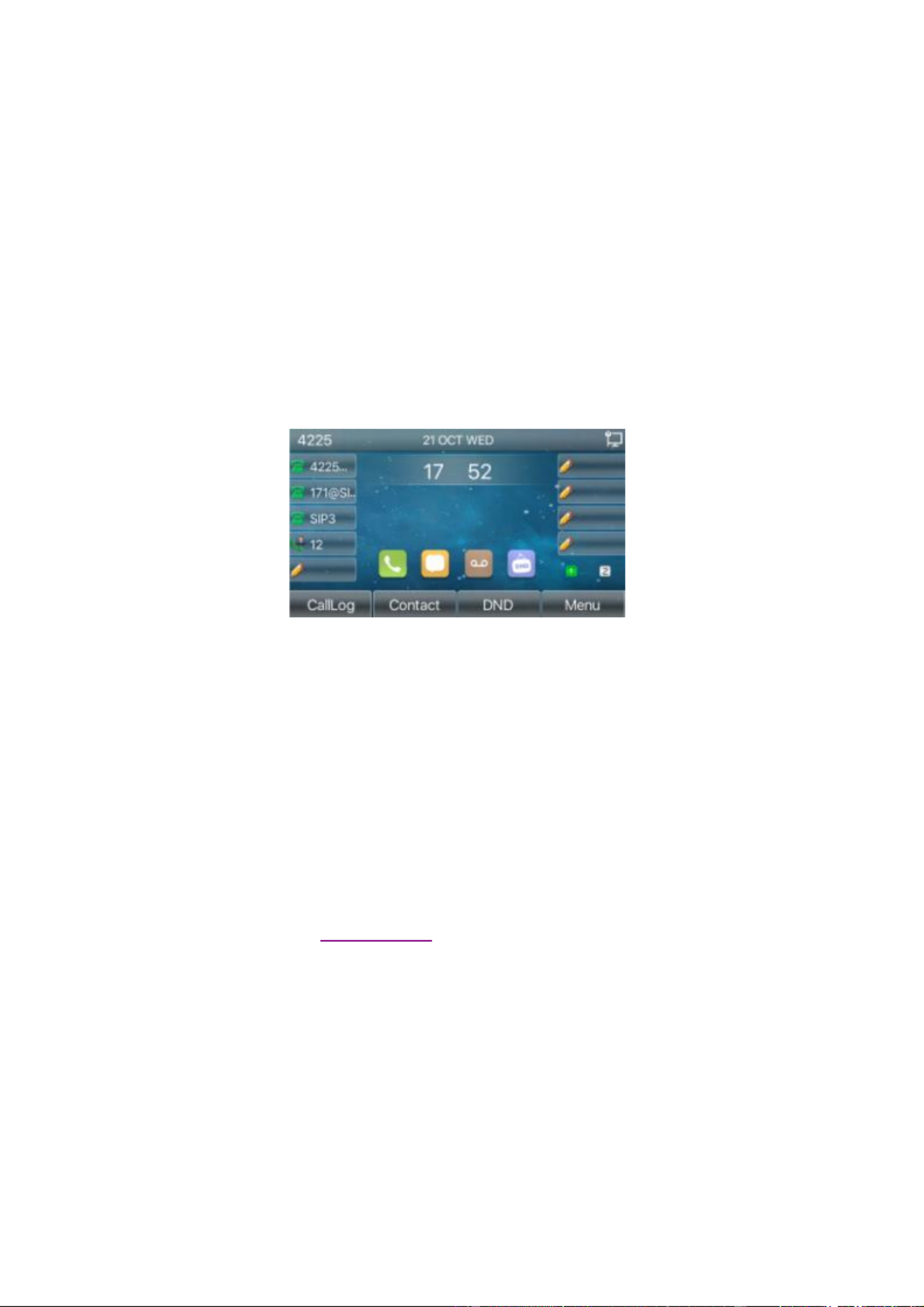
7.4 Idle Screen
Picture 5 - Screen layout/default home screen
The image above shows the default standby screen, which is the user interface most of the time.
The upper half of the home screen shows the status of the device, information and data that can be edited
(such as voice messages, missed calls, auto answer, do not disturb, lock status, network connection status,
etc.).
The lower half of the area are the function menu keys, which are also the first layer of function menu keys,
through which users can operate the phone.
Users can restore the phone to the default standby screen interface by picking up and dropping the handle.
The left and right part of the area shows default configuration of Side keys, which dynamically display the
configuration of SIP information, message, headset, etc., which can be customized by users.
The icon description is described in 6.1 appendix I.
In some screens, there are many items or long text to be displayed which could not fit into the screen. They
will be arranged in a list or multiple lines with a scroll bar. If the user sees a scroll bar, he can use up/down
navigator buttons to scroll the list. By long-pressed the navigator keys, user can scroll the list or items in a
faster speed.
/ 12228
Picture 6 - Scroll icon
7.5 Phone Status
The phone status includes the following information about the phone:
Network Status:
VLAN ID
IPv4 or IPv6 status
IP Address
Network Mode
The Phone Device Information:
Mac Address
Phone Mode
Hardware Version number
Software Version number
Phone Storage (RAM and ROM)
System Running Time
SIP Account Information:
SIP Account
SIP Account Status ( register / uncommitted / trying / time out)
TR069 Connect Status (Displays only in the phone interface state)
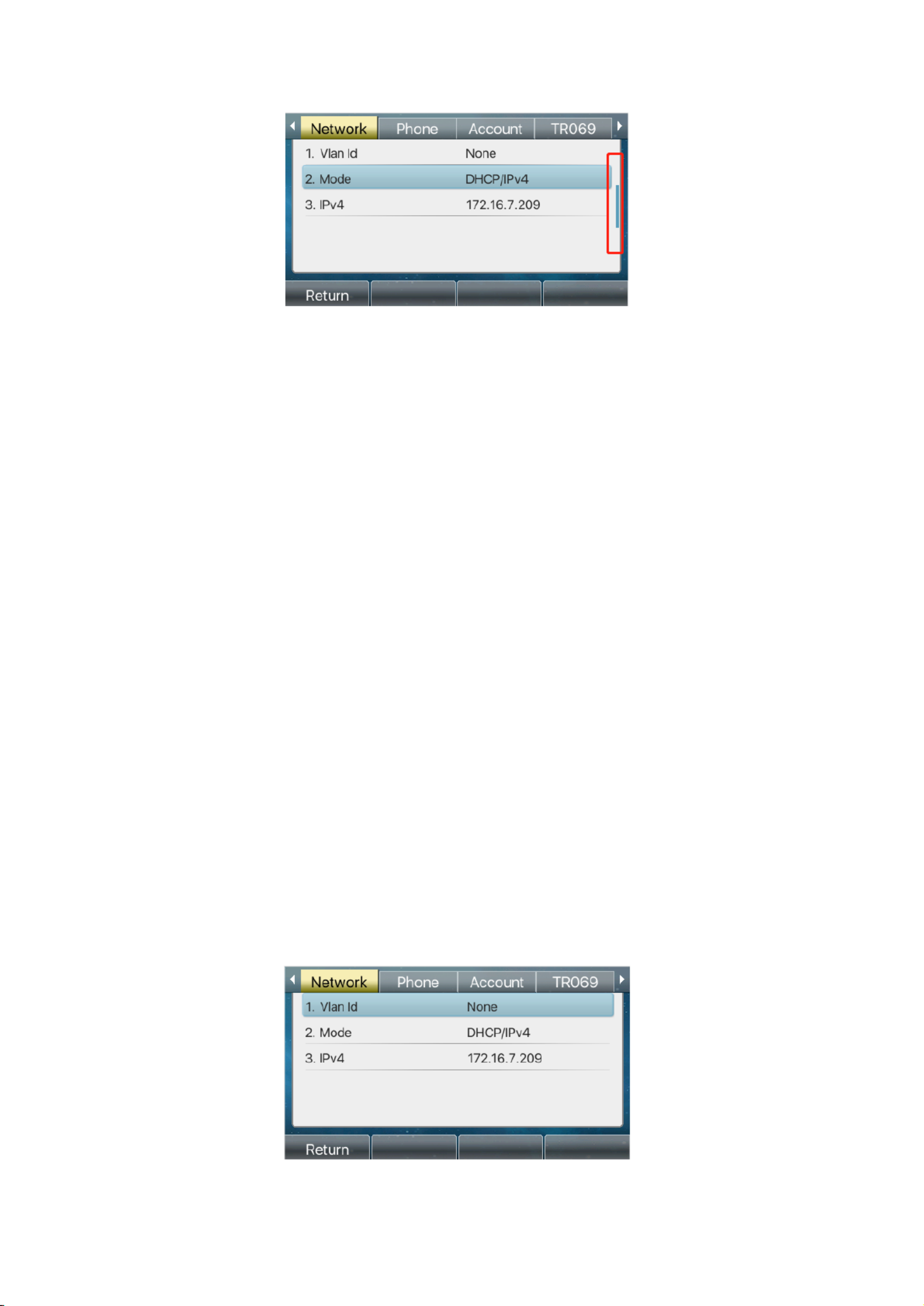
The user can view the phone status through the phone interface and the web interface.
Phone interface When the phone is in standby mode, press : 【 】Menu >> 【Status】 and select the
option to view the corresponding information, as shown in the figure:
Picture 7 - The Phone status

/ 12229
WEB interface Refer to 7.5 Web management to log in the phone page, enter the System : 【 】 >>
【Information page, and check the phone status, as shown in the figure: 】
Picture 8 - WEB phone status
7.6 Web Management
Phone can be configured and managed on the web page of the phone. The user needs to enter the IP
address of the phone in the browser and open the web page of the phone firstly. The user can check the IP
address of the phone by pressing [Menu] >> [Status].
Picture 9 - Landing page
Users must correctly enter the user name and password to log in to the web page. The default user name and
password are "admin". For the specific details of the operation page, please refer to page 11 Web
configuration.

/ 12231
virtualized SIM card on a mobile phone which stores the service provider and the account information used
for registration and authentication. When the device is applied with the configuration, it will register the device
to the service provider with the server’s address and user’s authentication as stored in the configurations.
The user can conduct line configuration on the interface of the phone or the webpage, and input the
corresponding information at the registered address, registered user name, registered password and SIP
user and registered port respectively, which are provided by the SIP server administrator.
Phone interface To manually configure a line, the user can press the line key for a long time, or press the :
button in the function menu [Menu Advanced Settings Accounts Line n] >> [ ] >> [ ] >> [ ] configuration,
click ok to save the configuration.
NOTICE! User must enter correct PIN code to be able to advanced settings to edit line configuration.
(The default PIN is 123)
The parameters and screens are listed in below pictures.
Picture - Phone line SIP address and account information 10
WEB interface: After logging into the phone page, enter [ ] and select Line] >> [SIP SIP for configuration,
click apply to complete registration after configuration, as shown below:
Picture - Web SIP registration11

/ 12232
8 Basic Function
8.1 Making Phone Calls
Default Line
The device provides twenty line services. If both lines are configured, user can make or receive phone calls
on either line. If default line is configured by user, there will be a default line to be used for making outgoing
call which is indicated on the top left corner. To change the default line, user can press left/right navigator
buttons to switch between two lines. Enable or disable default line, user can press [Menu Features] >> [ ] >>
[General] >> [Default Line] or configure from Web Interface (Web / PHONE / Features / Basic Settings).
Picture - Default line 12
Dialing Methods
User can dial a number by,
Entering the number directly
Selecting a phone number from phonebook contacts (Refer to 10.2.1 Local contacts)
Selecting a phone number from cloud phonebook contacts (Refer to 10.2.3 Cloud Phone Book)
Selecting a phone number from call logs (Refer to 10.3 Call Log)
Redialing the last dialed number
Dialing Number then Opening Audio
To make a phone call, user can firstly dial a number by one of the above methods. When the dialed number is
completed, user can press [ ] button on the soft-menu, or press hand-free button to turn on the speaker or Dial
headphone, or lift the handset to call out with the current line, or user can press line key(Configured by DSS
Keys) to call out with specified line.

33 / 122
Picture - Enable voice channel dialing 13
Opening Audio then Dialing the Number
Another alternative is the traditional way to rstly open the audio channel by lifting the handset, then turn on
the hands-free speaker or headphone by pressing hands-free button, or line key, and then dial the number
with one of the above methods. When completing the number dial, user can press [ ] button or [ ] button Dial OK
to call out, or the number can also be dialed out automatically after timeout.
Picture - Open the voice channel and dial the number 14
Cancel Call
While calling the number, user can stop the audio channel by putting back the handset or pressing the
hands-free button to drop the call.
Picture - Call number 15
8.2 Answering Calls
When there is an incoming call while the device is idle, user will see the following incoming call on the screen.
Picture - Answering calls 16
/ 12234
User can answer the call by lifting the handset, open headphone or speaker phone by pressing the
hands-free button, or the [Answer] button. To divert the incoming call, user should press [ ] button. To Divert
reject the incoming call, user should press [ ] button. Reject
8.2.1 Talking
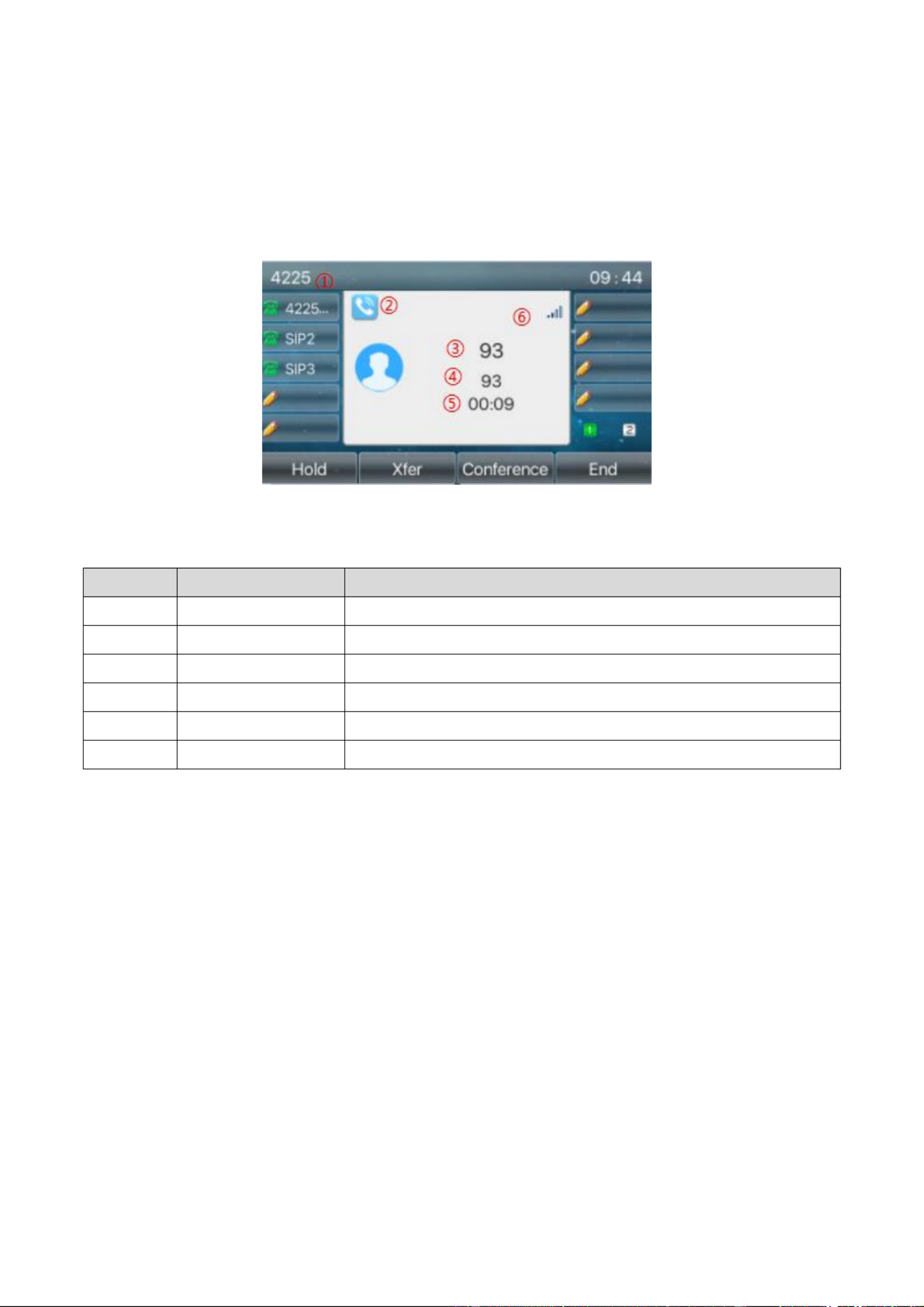
When the call is connected, user will see a talking mode screen as the following figure.
Picture - Talking interface 17
Table 8 - Talking mode
Number
Name
Description
①
①
①
①①
Default line
The line currently used by the phone.
②
②
②
②②
Voice channel
The icon shows the voice channel mode being used.
③
③
③
③③
Calls to end
The name or number of the person on the other end of the call.
④
④
④
④④
Call duration
The duration of a call after it has been established.
⑤
⑤
⑤
⑤⑤
Numbers of line
Shows how many calls are present on the current device
⑥
⑥
⑥
⑥⑥
Speech quality
Displays the current voice quality of the call.
8.2.2 Make / Receive Second Call
The device can support up to two concurrent calls. When there is already a call established, user can still
answer another incoming call on either lines or make a second call on either lines.
Second Incoming Call
When there is another incoming call during talking a phone call, this call will be waiting for user to answer.
User will see the call message in the middle of current screen. The device will not be ringing but playing call
waiting tone in the audio channel of the current call and the LED will be flashing in green. User can accept or
reject the call as same as normal incoming call. When the waiting call is answered, the first call will be ld he on
automatically.

/ 12235
Picture - The second call interface 18
Second Outgoing Call
To make a second call, user may press [Xfer] / [Conf] button to make a new call on the default line or press
the line key to make new call on specific line. Then dial the number the same way as making a phone call.
Another alternative for making second call is to press DSS Keys or dial out from the configured Keys
(BLF/Speed Dial). When the user is making a second call with the above methods, the first call could be held
on manually or will be ld on automatically at second dial. he
Switching between Two Calls
When there are two calls established, user will see a dual calls screen as the following picture.
Picture - Two way calling 19
User can press up/down navigator buttons to switch screen page, and switch call focus by pressing [Resume]
button.
Ending One Call
User may hang up the current talking call by closing the audio channel or press [ ] button. The device will End
return to single call mode in holding state.
8.3 End of the Call
After the user finishes the call, the user can put the handle back on the phone, press the hands-free button or
Softkey [ ] key to close the voice channel and end the call. End
Note! When the phone is on hold, the user must press the [Resume] button to return to the call state
to end the call.

/ 12236
8.4 Redial
Redial the last outgoing number:
When the phone is in standby mode, press the redial button and the phone will call out the last outgoing
number.
Call out any number with the redial key:
Enter the number, press the redial key, and the phone will call out the number on the dial.
Press the redial key to enter the call record:
Log in the phone page, enter [Phone Settings Features Redial Settings Redial] >> [ ] >> [ ], check to
enter the call record page, press the redial button when standby to enter the call record page, and press
again to call out the current located number.
Picture - Redial set 20
8.5 Dial-up Query
The phone is defaulted to turn on the dial-up inquiry function, dial-out, enter two or more numbers. The dial
interface will automatically match the call records, contacts in the number list. Use the navigation key and up
and down keys to select the number, press the call out key or wait for time out.
8.6 Auto-Answering
User may turn on the auto-answering mode on the device and any incoming call will be automatically
answered (not including call waiting). The auto-answering can be enabled on line basis.
The user can start the automatic answer function in the telephone interface or the webpage interface.
Phone interface:
Press [Menu] >> [Features Auto Answer] >> [ ] button;
Press the button to select the line, use the left/right navigation key to turn on/off the auto answer option, and
set the auto answer time to 5 seconds by default.
After completion, press [ ] key to save; OK
The icon in the upper right corner of the screen indicates that auto answer is enabled.

/ 12237
Picture - Line 1 enables auto-answering 21
Picture - The line has enabled auto-answering 22
WEB interface:
Log in the phone page, enter [ ], select [Line] >> [SIP SIP Basic settings] >> [ ], start auto-answering, and
click apply after setting the automatic answering time.
Picture - Web page to start auto-answering 23
8.7 Callback
The user can dial back the number of the last call. If there is no call history, press the [ ] button and Callback
the phone will say "can't process".
Set the callback key through the phone interface:
Under standby, press [Menu] >> [Basic Settings Keyboard Settings Function key] >> [ ] >> [ ] or

/ 12238
[ Keyboard Settings Soft function key ] >> [ ] choose to set up the function keys, key type, type
selection function name select callback function, input the callback key name, press [ ] key to save. OK
Picture - Set the callback key on the phone 24
Set the callback key through the web interface:
Log in the phone page, enter the [Function Key] >> [Side Key] or [Function Key] >> [Function Key]
page, select the function Key, set the type as the function Key, and set the subtype as the callback, as
shown in the gure:
Picture - Set the callback key on the web page 25
8.8 Mute
You can turn on mute mode during a call and turn off the microphone so that the local voice is not heard.
Normally, mute mode is automatically turned off at the end of a call. You can also turn on mute on any screen
(such as the free screen) and mute the ringtone automatically when there is an incoming call.
Mute mode can be turned on in all call modes (handles, headphones or hands-free).
8.8.1 Mute the Call
During the conversation, press the mute button on the phone: the mute button on the phone will turn
on the red light.
Red mute icon is displayed in the call interface, as shown in the gure:

/ 12239
Picture - Mute the call 26
Cancel mute: press cancel mute on the phone again. The mute icon is no longer displayed in the call
screen. The red light is o by mute button.
8.8.2 Ringing Mute
Mute: press the mute button when the phone is in standby mode:
The top right corner of the phone shows the bell mute icon Mute button red light is always on, when ,
there is an incoming call, the phone will display the incoming call interface but will not ring.
Picture - Ringing mute 27
Cancel ring tone mute: On the standby or incoming call screen, press the mute button again or
volume up cancel ring tone mute no longer shows mute icon in upper right corner after ,
cancel .The phone mute icon is o .
8.9 Call Hold/Resume
The user can press the [ ] button to maintain the current call, and this button will become the [ Hold Resume ]
button, and the user can press the "resume" button to restore the call.

/ 12240
Picture - Call hold interface 28
8.10 DND
User may enable Do-Not-Disturb (DND) feature on the device to reject incoming calls (including call waiting).
The DND can be enabled on line basis.
Enable/Disable phone all lines DND, the methods the following as :
Phone interface Default standby mode : ,
1) Press [ ] button to enter the DND setting interface, select line or phone to enable DND. DND
2) Press [ ] button to enter the DND setting interface disable DND. DND and
Picture - Enable DND 29
If the user wants to enable/disable the uninterrupted function on a specific line, the user can set the
uninterrupted function on the page of conguring the line.
1) Press [Menu Features] >> [ ] >> [DND] button, Enter the [DND] to edit the interface.
2) Click the left/right navigation button to select the line to adjust the mode and state of "do not disturb",
and then press the [ ] button to save. OK
The user will see the DND icon turn red, and the sip-line has enabled the mode of "DND".
Picture - DND setting interface 30
The user can also use the DND timer. After the setting, the DND function will automatically turn on and the
DND icon will turn red when ringing.
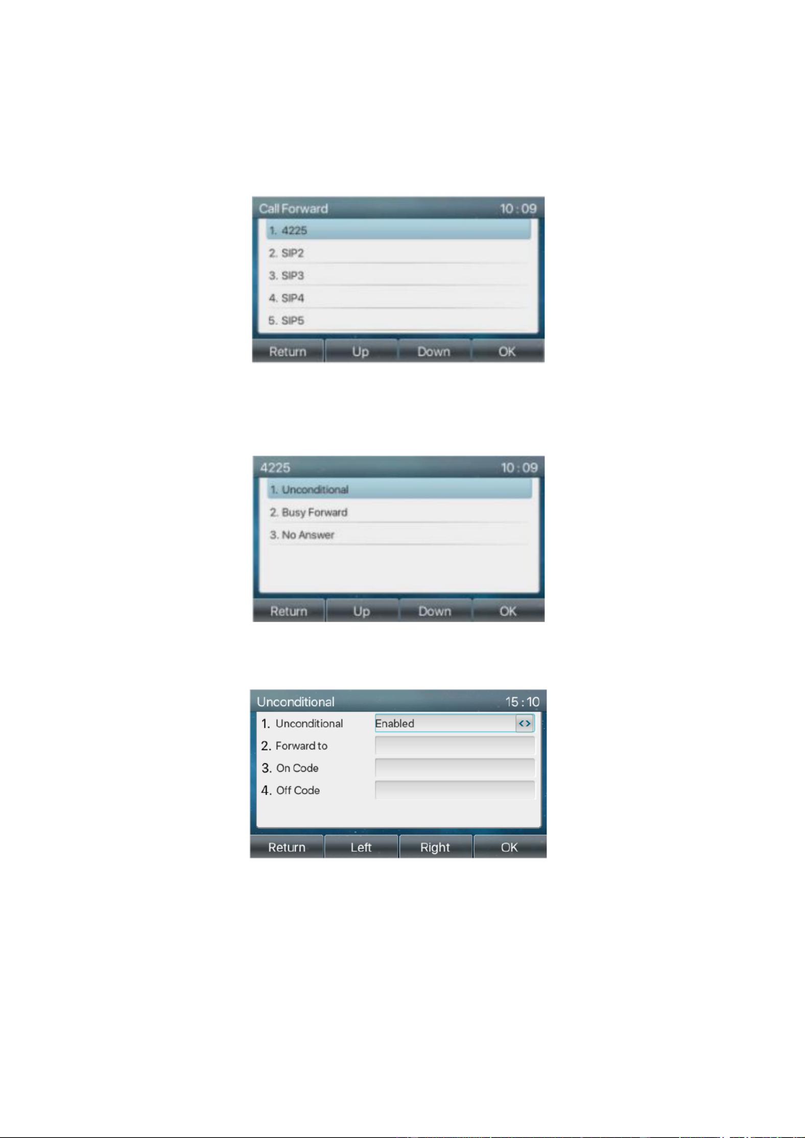
/ 12242
time, the incoming call will be forwarded to the congured number.
Phone interface Default standby mode :
1) Press [Menu Features Call Forward] >> [ ] >> [ ] button, select the line by up/down navigation key,
press [ ] button to set call forward. OK
Picture - Select the line to set up call forwarding 34
2) Select the call forward type by pressing the up/down navigation button. Click [ ] to congure call OK
forwarding and delay time.
Picture - Select call forward type 35
3) Select enable/disable by pressing the left/right navigation button.
Picture - Enable call forwarding and congure the call forwarding number 36
4) Browse the parameters set by the up/down navigation key and enter the required information. When
nished, press the [ ] button to save the changes. OK
WEB interface Enter [: Line SIP Line Basic settings] >> [ ], Select a [ ] >> [ ], and set the type, number and
time of forward forwarding.

/ 12243
Picture - Set call forward 37
8.12 Call Transfer
When the user is talking with a remote party and wish to transfer the call to another remote party, there are
three way to transfer the call, blind transfer, attended ansfer and Semi-Attended transfer. tr
Blind transfer No need to negotiate with the other side, directly transfer the call to the other side. :
Semi-Attended transfer When you hear the ring back, transfer the call to the other party. :
Attended transfer: When the caller answers the call, transfer the call to the other party.
Note For more transfer Settings, please refer to !12. Line >> Dial Plan7
8.12.1 Blind transfer
During the call, the user presses the function menu button [Transfer] or the transfer button on the phone ,
Enter the number to transfer or press the contact button or the history button to select the number, press the
transfer key again or blind transfer to a third party. After the third party rings, the phone will show that
the transfer is successful and hang up.
Picture - Transfer interface 38
8.12.2 S -Attended transfer emi
During the call, the user presses the function menu button [transfer] or the transfer button on the phone
to input the number to be transferred or press the contact button or the historical record button to select the
number, and then press the call button. When the third party is not answered, press the transfer on the call
interface to make the semi-attendance transfer or press the end button to cancel the semi-attendance
transfer.

/ 12244
Picture - Semi-Attended transfer 39
8.12.3 Attended transfer
Attendance transfer is also known as "courtesy mode", which is to transfer the call by calling the other party
and waiting for the other party to answer the call.
The same procedure to calling. In dual call mode, press the "transfer" button to transfer the rst call to the
second call.
Picture - Attended transfer 40
8.13 Call Waiting
Enable call waiting: new calls can be accepted during a call.
Disable call waiting: new calls will be automatically rejected and a busy tone will be prompted.
Enable call waiting tone: when you receive a new call on the line, the tone will beep.
The user can enable/disable the call waiting function in the phone interface and the web interface.
Phone interface Press [: Menu Features Call waiting] >> [ ] >> [ ], the navigation key left/right button and
enable/disable call waiting and call waiting tone. Press [ Features Call waiting], the Menu] >> [ ] >> [
navigation key left/right button enable/disable call waiting and call waiting tone. and

/ 12245
Picture - Call waiting setting 41
WEB interface: Enter [Phone Settings] [>> Features] [>> Basic Settings] enable/disable call waiting ,
and call waiting tone.
Picture - Web call waiting setting 42
Picture - Web call waiting tone setting 43
8.14 Conference
8.14.1 Local Conference
To conduct local conference, the user needs to log in the webpage and enter [Line] >> [SIP] >> [Basic
settings]. The meeting mode is set as local (the default is local mode), as shown in the gure:

/ 12246
Picture - Local conference setting 44
Two ways to create a local conference:
1) The device has two channels of communication. Press the conference button on the call interface. When
selecting the conference number, select the other number that already exists.
Picture - Local conference (1) 45
2) If the device has a call all the way, press the conference key in the call interface, enter the number to join
the meeting and press the call; After the opposite end is answered, press the conference button again to
set up the local tripartite conference:
Picture - Local conference (2) 46
Note During the conference, press the split button to split the conference and press the end button to end the :
call.
8.14.2 Network Conference
Users need server support for network conference.
Log in the web page, enter [ ] >> [Line] >> [SIP Basic settings], set the conference mode as server mode
(default is local mode), set the server conference room number (please consult your system administrator),
as shown in the gure:

/ 12247
Picture - Network conference 47
Method to join a network conference:
Multi-party call number of network conference room and enter the password then all enter the
conference room.
The two phones have established common calls. Press the conference button to invite new members to
the conference. Follow the voice prompt to operate.
Note: the upper limit of the number of participants in the network conference varies according to the server.
8.15 Call Park
Call park requires server support. Consult your system administrator for support.
When you are on the call, if it is not convenient to answer the phone at this time, you can press the congured
park button to hold the call; After a successful park, you can resume the call by pressing the congured park
button on other devices.
Set the call park button:
Phone interface: long press a function key to enter the function key Settings interface, or through the
[Menu] >> [Basic Settings Keyboard Settings] >> [ ] enter the settings interface of function keys, and
set the key function type as memory and subtypes as call park, reside values for the server calls park
number, set up corresponding SIP lines.
WEB interface: log in the phone page, enter the [Function Key] >> [Function Key] page, select a
DSSkey, set the function key type as memory key, the subtype as call park, and the value as the call park
number of the server, and set the corresponding SIP line.
Picture - Phone set call park 48

/ 12248
Picture - WEB set call park 49
8.16 Pick Up
Pick up requires server support. Consult your system administrator for support.
You can use the Pick Up function to answer incoming calls from other users. The phone can pick up incoming
calls by configuring DSSkey for BLF and setting the Pick Up code.
Phone interface: press [Menu Basic Settings Keyboard Settings DSS Key Settings] >> [ ] >> [ ] >> [ ], select
the function key to set.
Set the line, function key type as memory key, subtype as BLF/NEW CALL, set subscription number, and
pick up code.
Other phones call the subscription number, and the opposite end is in the incoming ring.
Press the DSS key to pick up the phone.
The caller picks up the call and speaks to it.
WEB interface: Log in the phone webpage, enter the [Function Key] >> [Function Key] page, select a
DSSkey, set the memory key type as memory key, the subtype as BLF/NEW CALL, and set the
corresponding SIP line and pick up codes.
Picture - Phone pick up setting 50

/ 12249
Picture - WEB pick up setting 51
8.17 Anonymous Call
8.17.1 Anonymous Call
The phone can set up anonymous calls to hide the calling number and the calling name.
You can see anonymity in the context of [Menu System ] >> [ ] >> [Accounts Advanced] >> [ ].
The default is none, which is off, and RFC3323 and RFC3325 are optional.
Select any one to open the anonymous call.
Picture - Enable anonymous call 52
On the web page [ ] can also open the mode of anonymous calls. Line] >> [SIP] >> [Advanced Settings
Setting to enable anonymous calls also corresponds to the SIP line. That is, the setting under the SIP1
page can only take eect on the SIP1 line.
Picture - Enable Anonymous web page call 53
The following is a transcript of an anonymous call received by the phone.

/ 12250
Picture - Anonymous call log 54
8.17.2 Ban Anonymous Call
The device can be set to prohibit anonymous calls, that is anonymous calls to the number will be directly
rejected.
In the phone [Menu Features Ban anonymous call] >> [ ] >> [ ], click to enter and all SIP lines will be
displayed.
Click Softkey [ ] or [ ] to switch the SIP line and enable anonymous call.Switch <] [>
Picture - Anonymous calls are not allowed on the phone 55
On the web page [Line] >> [SIP] >> [Advanced Settings], also can disable anonymous calls.
The setup to disable anonymous calls also corresponds to the SIP line. That is, the setting under the
SIP1 page can only take effect on the SIP1 line.
Picture - Page Settings blocking anonymous call 56
8.18 Hotline
The device supports hotline dialing. After setting up the hotline dialing, directly pick up the handset,
hands-free, earphone, etc., and the phone will automatically call according to the hotline delay time.
In the phone [Menu Feature Advanced Hotline] >> [ s] >> [ ] >> [ ], click to enter and all SIP lines will be

/ 12251
displayed.
Then set the hotline for each SIP line, which is off by default.
Open the hotline, set the hotline number, set the delay time of the hotline.
Picture - Phone hotline setting interface 57
On the website [ ], can also set up a hotline. Line] >> [SIP] >> [Basic Settings
The setup hotline also corresponds to the SIP line. That is, the hotline set in the SIP1 webpage can only
be activated in the SIP1 line.
Picture - Hotline set up on webpage 58
8.19 Emergency Call
The emergency call function is used to et the corresponding emergency call number on the phone after
enabling the keypad lock. You can also call emergency services when your phone is locked.
1) Congure the emergency call number: log in the phone page, enter the [Phone Settings Function ] >> [
Settings Basic Settings]>> [ ]page, set up the emergency call code, if you need to set up more than one

/ 12252
emergency call code, please use ", "to separate.
Picture - Set up an emergency call number 59
2) When the phone set the keyboard lock, you can call the emergency call number without unlocking, as
shown in the gure:
Picture - Dial the emergency number 60

/ 12253
9 Advance Function
9.1 BLF (Busy Lamp Field)
9.1.1 Congure the Functionality BLF
Page interface: log in the phone page, enter the [Function key] >> [ ] page, select a DSS key, Side key
set the function key type as memory key, choose subtype among BLF/NEW CALL, BLF/BXFER,
BLF/AXFER, BLF/CONF, set BLF/DTMF value as the number to be subscribed, set the corresponding
SIP line. The pickup number is provided by the server. The specific usage refers to .8.16 Pick up
Picture - Web page conguration BLF function key 61
Phone interface: long press a function key to enter the function key Settings interface, or go to the
[ [Menu] >> Basic Settings] [ >> Keyboard Settings] enter to [Soft function key] to set the settings
interface, set the key function types as memory keys and a subtype of BLF/NEW CALL, BLF/BXFER,
BLF/AXFER, BLF/CONF, BLF/DTMF. The values is the subscription number, and set up corresponding
SIP lines.
Pictur - Phone conguration BLF function key e 62
Table 9 - BLF Function key subtype parameter list
Subtype
Standby is described
Calling is described
BLF/NEW
CALL
Pressing the BLF key while standby to
dial the subscriber number.
When you press this BLF key while talking to
another user, you create a new call along with the
subscribed number.
BLF/BXFE
R
Pressing the BLF key while standby to
dial the subscriber number.
When you press this BLF key while talking to
another user, you blind transfer the call to the

/ 12255
changed.
Congure BLF List function: log in the phone page, enter the [Line] >> [SIP] >> [Advanced settings] page,
open the BLF List, and configure the BLF List number.
Picture - Congure the BLF List functionality 63
Use the BLF List function: when the conguration is completed, the phone will automatically subscribe to the
contents of the BLF List group. Users can monitor, call and transfer the corresponding number by pressing
the BLF List key.
Picture - BLF List number display 64
9.3 Record
The device supports recording during a call.
9.3.1 Local Record
When using local recording, it is necessary to start recording on the phone page [Application Manage ] >> [
recording], select the local type and set the voice coding. The webpage is as follows:
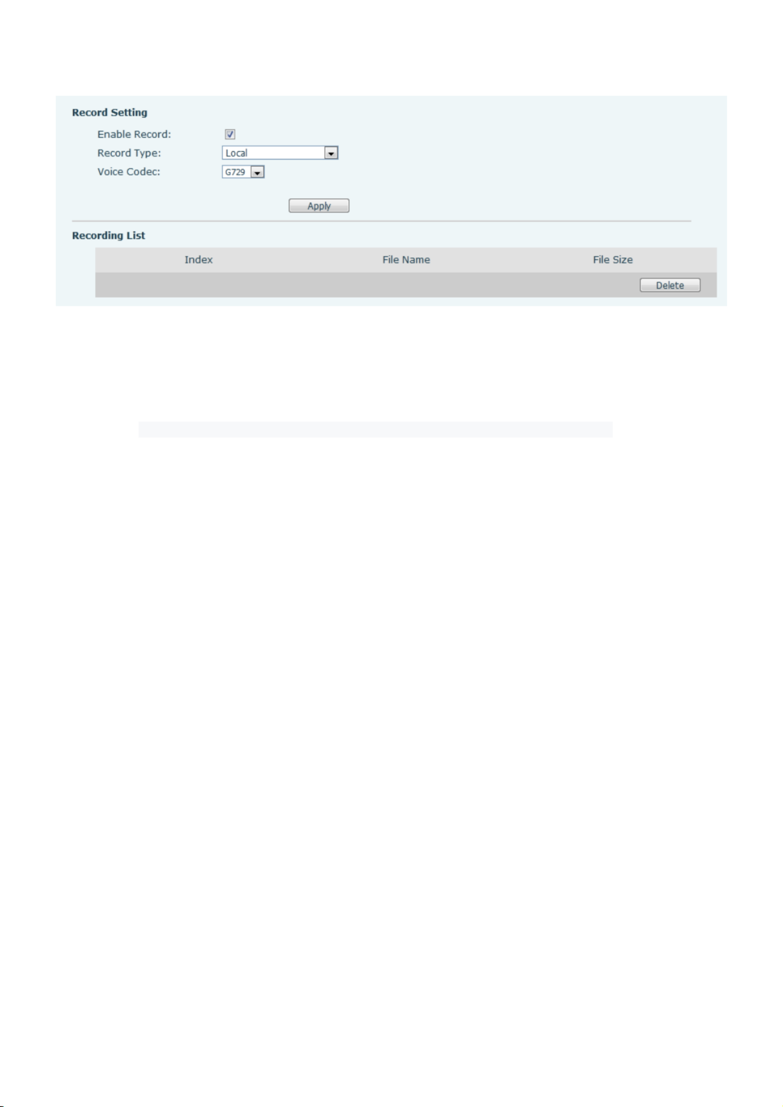
/ 12256
Picture 65 - WEB local recording
Local recording steps:
Open the recording on the web page, and set the recording type as local recording.
Set DSSkey type as key event and type as record in the phone/web interface.
Set up one line call and press the recording key (set DSSkey).
End the recording. End the call.
View local recording:
Enter [Application Sound Recorder] >> [ ]
Enter view the recording le.
Or enter the webpage [Application] under the [Manage recording] to view the recording le.
Listen to the record :
Enter [Application Sound Recorder] >> [ ].
Enter view the recording le.
Select the recording le that you want to listen to, and click listen to the recording.
9.3.2 Server Record
When using the network server to record, it is necessary to open the recording in the phone web page
[Application Manage recording] >> [ ]. The type is selected as network, and the address and port of the
recording server are lled in and the voice coding is selected. The web is as follows:

/ 12257
Picture 66 - Web server recording
9.3.3 SIP INFO Record
The phone is registered with a server that supports SIP INFO recording. After registering the account, check
the recording module of [Application] >> [Manage recording] to open the recording, and the recording type
is SIP INFO.
Picture - Web SIP info recording 67
9.4 Agent
Agent (Agent function) of the phone can be realized: when multiple people use a device for Agent services at
different times, he or she can quickly register his or her SIP account on the same server. The Agent functions
of the phone can be divided into Normal and Hotel Guest. The Hotel Guest mode requires server support.
Normal Mode:
Configure agent function: set a DSSkey as agent, press the function key or enter the [Menu] >>
[Features] >> [Agent] to enter the agent page. The SIP server needs to be configured before the account
can be configured.

/ 12258
Picture - Configure the agent account in normal mode 68
Picture - Configure the proxy account-hotel Guest mode 69
Table - Agency mode 10
Parameter
Description
Normal mode
Number
Set the proxy account number.
User
Set the proxy account number to verify the user name.
Password
Set the proxy account number to verify the password.
Line
Select the SIP line.
CallLog
Users can choose to save all types, or delete.
Hotel Guest mode
Number
Set the proxy account number.
Password
Set the proxy account number to verify the password.
Line
Select the SIP line.
CallLog
Users can choose to save all types, or delete.
Using agent functions:
1) When he phone has been configured on SIP server, fill in the correct number and user name password,
click login and then the phone can be registered to the SIP server;
2) After registration, click logout and the phone can delete the user name and password, and log out of the
SIP account.
3) Click Unregister and the phone retains the user name and password, and logs out of the SIP account.

/ 12259
Picture - Agent logon page 70
9.5 Intercom
When the Intercom is enabled, it can automatically receive calls from the intercom.
Picture - Web Intercom configure 71
Table - Intercom configure 11
Parameter
Description
Enable Intercom
When intercom is enabled, the device will accept the incoming call request with a SIP
header of Alert-Info instruction to automatically answer the call after specific delay.
Enable Intercom
Mute
Enable mute mode during the intercom call
Enable Intercom
Tone
If the incoming call is intercom call, the phone plays the intercom tone
Enable Intercom
Barge
Enable Intercom Barge by selecting it, the phone auto answers the intercom call
during a call. If the current call is intercom call, the phone will reject the second
intercom call
9.6 MCAST
This feature allows user to make some kind of broadcast call to people who are in multicast group. User can
configure a multicast DSS Key on the phone, which allows user to send a Real Time Transport Protocol (RTP)
stream to the pre-configured multicast address without involving SIP signaling. You can also configure the
phone to receive an RTP stream from pre-configured multicast listening address without involving SIP
signaling. You can specify up to 10 multicast listening addresses.
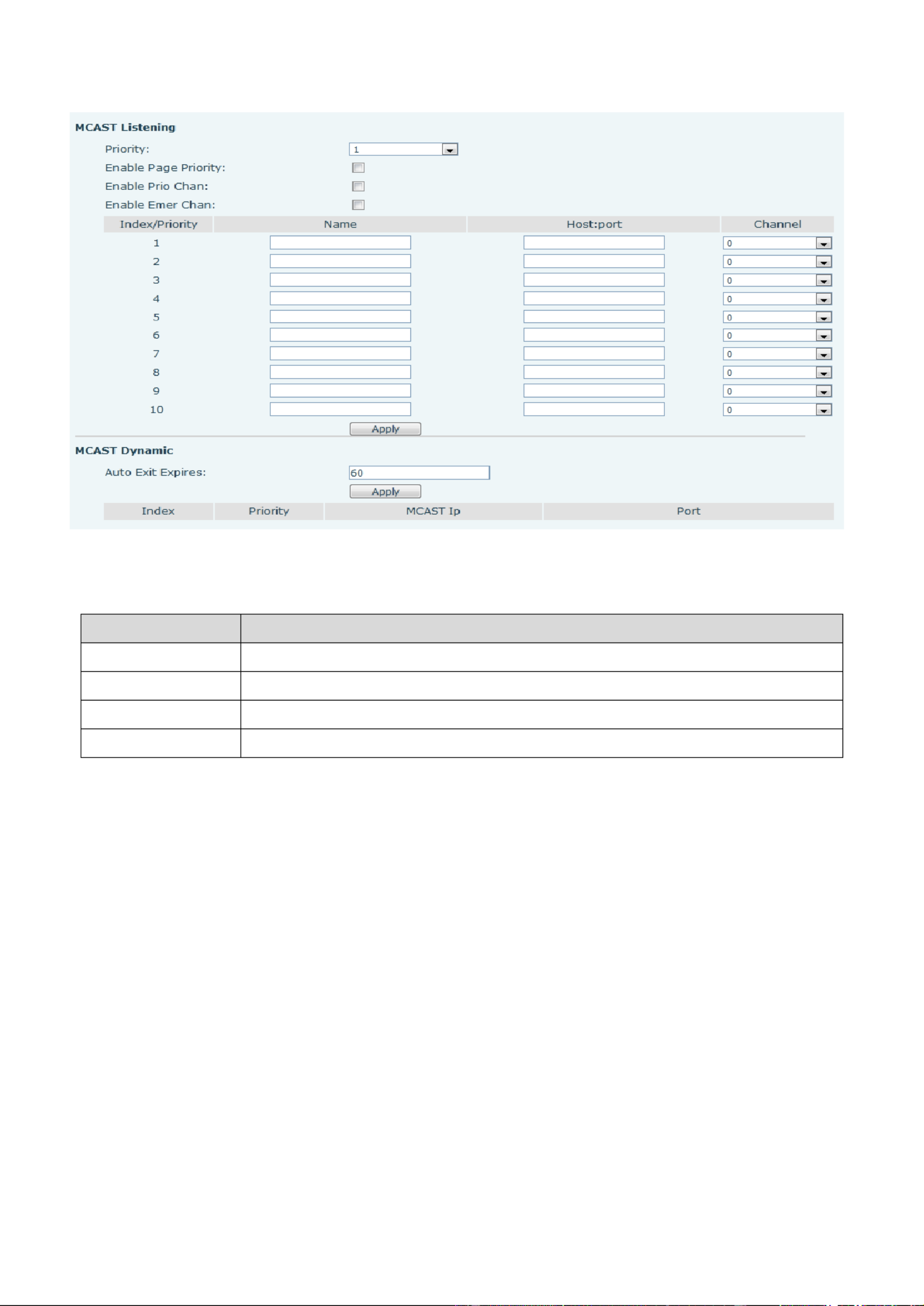
/ 12260
Picture - Multicast Settings Page 72
Table - MCAST Parameters on Web 12
Parameters
Description
Normal Call Priority
Define the priority of the active call, 1 is the highest priority, 10 is the lowest.
Enable Page Priority
The voice call in progress shall take precedence over all incoming paging calls.
Name
Listened multicast server name
Host:port
Listened multicast server’s multicast IP address and port.
Multicast:
Go to web page of [Function Key] >> [Function Key] , select the type to multicast, set the multicast
address, and select the codec.
Click Apply.
Set up the name, host and port of the receiving multicast on the web page of [Phone Settings] >>
[ MCAST].
Press the DSSKY of Multicast Key which you set.
Receive end will receive multicast call and play multicast automatically.
9.7 SCA (Shared Call Appearance)
Users need the support of server end to use SCA function. You can refer to
1) Configure on Phone
When registering with the BroadSoft server, Phone can register the account created previously on
multiple terminals.

/ 12261
Picture - Register BroadSoft account 73
After the phone set registers with the BroadSoft server, a server type needs to be set. Specically, log in
to the webpage of the phone set, choose [ [Line] >> SIP Advanced Settings] >> [ ] and set Specic
Server Type to BroadSoft, as shown in the following gure.
Picture - Set BroadSoft server 74
If a phone needs to enable the SCA function. Specically, log in to the webpage of the phone set,
choose [ [Line] >> SIP Advanced Settings] >> [ ], and select Enable SCA. If SCA is not enabled, the
registered line is the private line.

/ 12262
Picture - Enable SCA 75
After an account is congured and successfully registered, you can congure lines whose DSS Key is Shared
Call Appearance on the Function Key page to facilitate viewing the call status of the group. Each line key
represents a call appearance. Understand the call status by referring to 6.3 Appendix LED .III –
To facilitate private hold, congure keys whose DSS Key is Private Hold on the Function Key page. Pay
attention that the public hold key is the softkey-hold key during a call.
Picture - Set Private Hold Function Key 76
Each phone registered with the BroadSoft server should be congured as above, then the SCA function
can be used.
2) LED Status
To facilitate viewing the call status of a group, congure the DSS Key as SCA. The following table describes
the LEDs of lines in dierent states.
Table - LED Status of SCA 13
State&Direction
Local
Remote

/ 12263
Idle
O
O
Seized
Steady green
Steady red
Progressing (outgoing call)
Steady green
Steady red
Alerting (incoming call)
Fast blinking green
Fast blinking green
Active
Steady green
Steady red
Public Held (hold)
Slow blinking green
Slow blinking red
Held-private (private hold)
Slow blinking yellow
Steady red
Bridge-active (Barge-in)
Steady green
Steady red
Bridge-held
Steady green
Steady red
3) Shared Call Appearance(SCA)
The following lists a couple of instances to facilitate understanding.
In the following scenarios, the manager and secretary register the same SCA account and the account is
congured based on the preceding steps.
Scenario 1: When this account receives an incoming call, the phone sets of both the manager and the
secretary will receive the call and ring. If the manager is busy, the manager can reject the call and the
manager's phone set stops ringing but the secretary's phone set keeps ringing until the secretary
rejects/answers the call or the call times out.
Scenario 2: When this account receives an incoming call, if the secretary answers the call first and the
manager is required to answer the call, the secretary can press the Public Hold key to hold this call and notify
the manager. The manager can press the line key corresponding to the SCA to answer the call.
Scenario 3: The manager is in an important call with a customer and needs to leave for a while. If the
manager does not want others to retrieve this call, the manager can press the Private Hold key.
Scenario 4: The manager is in a call with a customer and requires the secretary to join the call to make
records. The secretary can press the corresponding SCA line key to barge in this call.
9.8 Messa ge
9.8.1 SMS
If the service of the line supports the function of the short message, when the other sends a text end
message to the number, the user will receive the notication of the short message and display the icon of the
new SMS on the standby screen interface.

/ 12265
Picture - Voice message interface 79
Picture - Configure voicemail number 80
9.9 SIP Hotspot
SIP hotspot is a simple but practical function. With simple configurations, the SIP hotspot function can
implement group ringing. SIP accounts can be expanded.
The users can set functions as a SIP hotspot and other phones set (B and C) function as SIP hotspot clients.
When somebody calls phone set A, phone sets A, B, and C all ring at the same time. When any phone set
answers the call, other phone sets stop ringing. The call can be answered by only one phone set. When B or
C initiates a call, the SIP number registered by phone set A is the calling number.
To set a SIP hotspot, register at least one SIP account.

/ 12266
Picture - Register SIP account 81
Table - SIP hotspot Parameters 14
Parameters
Description
Device Table
If your phone is set to “SIP hotspot server”, Device Table will display as Client
Device Table which connected to your phone.
If your phone is set to “SIP hotspot client”, Device Table will display as Server
Device Table which you can connect to.
SIP hotspot
Enable hotspot
Set it to be Enable to enable the feature.
Mode
Choose hotspot, phone will be a “SIP hotspot server”; Choose Client, phone will be
a “SIP hotspot Client”
Monitor Type
Either the Multicast or Broadcast is ok. If you want to limit the broadcast packets,
you’d better use broadcast. But, if client choose broadcast, the SIP hotspot phone
must be broadcast.
Monitor Address
The address of broadcast, hotspot server and hotspot client must be same.
Remote Port
Type the Remote port number.
Configure SIP hotspot server:

/ 12267
Picture - SIP hotspot server configuration 82
Configure SIP hotspot client:
To set as a SIP hotspot client, no SIP account needs to be set. The Phone set will automatically obtain and
configure a SIP account. On the SIP Hotspot tab page, set Mode to Client. The values of other options are the
same as those of the hotspot.
Picture - SIP hotspot client configuration 83
As the hotspot server, the default extension number is 0. When the phone is used as the client, the extension
number is increased from 1, you can view the extension number through the [SIP Hotspot] page.
Call extension number:
The hotspot server and the client can dial each other through the extension number.
For example, extension 1 dials extension 0.
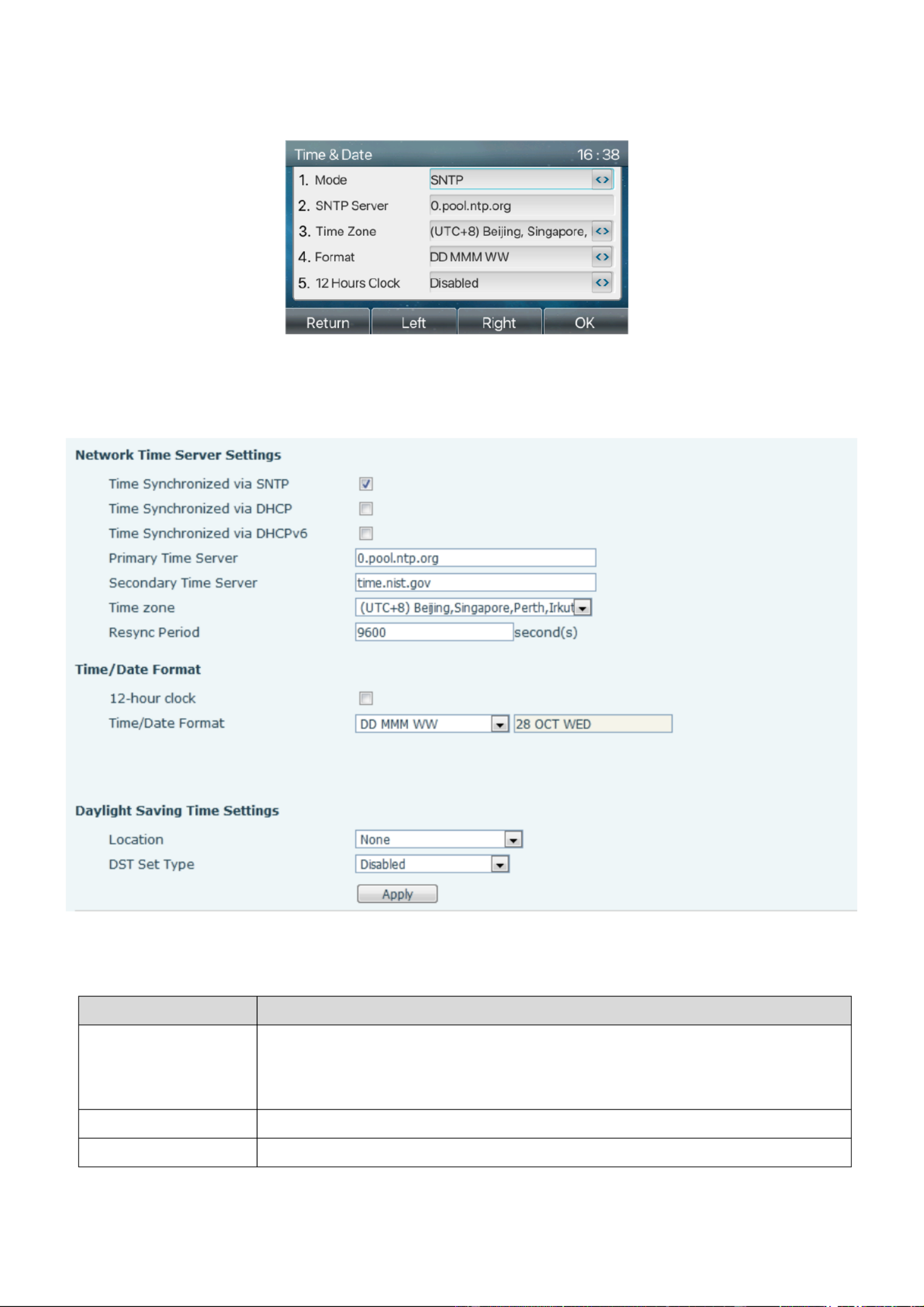
/ 12269
shown in the figure:
Picture - Set time & date on phone 86
Web end: Log in to the phone webpage and enter [Phone Settings Time/Date] >> [ ] , as shown in the
figure:
Picture - Set time & date on webpage 87
Table - Time Settings Parameters 15
Parameters
Description
Mode
Auto/Manual
Auto: Enable network time synchronization via SNTP protocol, default enabled.
Manual: User can modify data manually.
SNTP Server
SNTP server address
Time zone
Select the time zone

/ 12270
Time format
Select time format from one of the followings:
1 JAN, MON
1 January, Monday
JAN 1, MON
January 1, Monday
MON, 1 JAN
Monday, 1 January
MON, JAN 1
Monday, January 1
- - DD MM YY
- - DD MM YYYY
- - MM DD YY
- - MM DD YYYY
YY- - MM DD
YYYY- - MM DD
Separator
Choose the separator between year and moth and day
12-Hour Clock
Display the clock in 12-hour format
Daylight Saving Time
Enable or Disable the Daylight Saving Time
10.1.3 Screen
The user can set the phone screen parameters through both of the phone interface and web interface.
Phone: When the phone is in the default standby state, go to [ ] >> [Menu Basic] >> [Screen Settings] to
edit the screen parameters. After editing, click [ ] to save, as shown in the figure: OK
Picture - Set screen parameters on phone 88
Web : Go to [Phone Settings Advanced] >> [ ] Advanced, edit the screen parameters, and click Apply to
sav e.
10.1.3.1 Brightness and backlight
Set the brightness level in use from 1 to 16, [ ] or [ ] switch brightness level. < >
Set the brightness level in the energy-saving mode from 0 to 16, [ ] or [< >] switch the brightness level.
Set the backlight time to 30 seconds by default. You can turn it off or select 15 seconds /30 seconds /45
seconds /60 seconds /90 seconds /120 seconds.

/ 12272
volume for different mode.
Save the adjustment by pressing [ when done. OK]
10.1.6 Greeting Words
When the device is in the default standby mode,
Press soft-button [ till you find the [Menu] Basic] item.
Enter [Basic] item till you find [Greeting Words] item.
Press [ to enter the setting interface to edit the Greetings Words. OK]
Save the adjustment by pressing [ when done. OK]
NOTICE! The welcome message can only be displayed in the upper left corner of standby mode when
the default option is disabled.
10.1.7 Reboot
When the device is in the default standby mode,
Press soft-button [ till you find the [Menu] Basic] item.
Enter [Basic] item till you find [Reboot] item.
Press [OK] a prompt message, "restart now," prompts the user.
[Press OK] to restart the phone or [Cancel].
The phone is in standby mode,
The configurable key is the restart key. [OK] Press [OK], a prompt message, "restart now" prompts the
user.
[Press OK] to restart the phone or [Cancel] to exit .
10.2 Phone Book
10.2.1 Local Contact
User can save contacts’ information in the pho book and dial the contact’s phone number(s) from the ne
phone book. To open the phone book, user should press soft-menu button [Contact] in the default standby
screen or keypad.
By default the phone book is empty, user may add contact(s) into the phone book manually or from call logs.
Picture - Phone book screen91
Note!Phone user account can store contact information, different models and specifications.

/ 12273
Picture - Local Phone book 92
When there are contact records in the phone book, the contact records will be arranged in the alphabet order.
User may browse the contacts with up/down navigator keys. The record indicator tells user which contact is
currently focused. User may check the contact’s information by pressing [ button. OK]
10.2.1.1 Add / Edit / Delete Contact
To add a new contact, user should press [Add] button to open Add Contact screen and enter the contact
information of the followings,
Contact Name
Tel. Number
Mobile Number
Other Number
Line
Ring Tone
Contact Group
Photo
Picture - Add New Contact 93
User can edit a contact by pressing [Option Edit] >> [ ] button.
To delete a contact, user should move the record indicator to the position of the contact to be deleted, press
[ [ ] button and confirm with [ Option] >> Delete OK].
10.2.1.2 Add / Edit / Delete Group
By default, the group list is blank. User can create his/her own groups, edit the group name, add or remove

/ 12274
contacts in the group, and delete a group.
To add a group, press [Add Group] button.
To delete a group, press [Option Delete] >> [ ] button.
To edit a group, press [Edit] button.
The Number behind the group name means the total contacts number of selected groups.
Picture - Group List 94
10.2.1.3 Browse and Add / Remove Contacts in Group
User can browse contacts in a group by opening the group in group list with [ ] button. OK
Picture - Browsing Contacts in a Group 95
When user is browsing contacts of a group, user can also add contacts in that group by pressing [Add] button
to enter the group contacts management interface, then press [ ] button to save the contact. The contact OK
will also be added in local phonebook User can delete contact from group by [ . Option] >> [Delete].
Picture - Add Contacts in a Group 96
10.2.2 Blacklist
The device Support blacklist, such as the number added to the blacklist, the number of calls directly refused

/ 12276
Picture - Cloud phone book list 99
10.2.3.2 Downloading Cloud Phone book
In cloud phone book screen, user can open a cloud phone book by pressing [ / [OK] Enter] button. The device
will start downloading the phone book. The user will be prompted with a warning message if the download
fails ,
Once the cloud phone book is downloaded completely, the user can browse the contact list and dial the
contact number same as in local phonebook.
Picture 100 - Downloading Cloud Phone book
Picture 101 - Browsing Contacts in Cloud Phone book
10.3 Call Log
The phone can store the call record (the quantity of storage varies according to different specications). The
user can press [ ] to open the call record and check the records of all incoming calls, outgoing calls CallLog
and missed calls.
In the call logs interface, user may browse the call logs with up/down navigator keys.

/ 12277
Each call log record is presented with ‘call type’ and ‘call party number / name’. User can check further call
log detail by pressing [ ] button and dial the number with [ ] button, or add the call log number to OK Dial
phonebook with pressing [ [Option] >> Add to Contact] .
User can delete a call log by pressing [ ] button and clear all call logs by pressing [Delete Delete All] button .
Picture 102 - Call Log
Users can also lter the call records of specic call types to narrow down the scope of search records, and
select a call record type by left and right navigation keys.
- Missed Call Log
- Incoming Call Log
- Outgoing Call Log
- Forward Call Log
Picture 103 - Filter call record types
10.4 Function Key
Users can use the page switch key to switch DSS display pages quickly. In addition, the user can also long
press each DSS key to modify the corresponding key Settings.

/ 12278
Picture 104 - DSS LCD key Page Configuration Screen
The DSS Key could be configured as followings,
Memory Key
Speed Dial/Intercom/BLF/Presence/Call Park/Call Forward (to someone)
Line
Key Event
MWI/DND/Hold/Transfer/Phonebook/Redial/Pickup/Call Forward (to specified line)/Headset/
SMS/Release
DTMF
Action URL
BLF List Key
Multicast
Action URL
XML Browser
Webpage interface: [Function key] >> [Function key].
Picture 105 - DSS settings
Moreover, user also can add the user-defined title for the DSS Keys, which is configured as Memory Key /
Line / URL / Multicast / Prefix.
More detailed information refers to 12.24 Side Key and 6.3 Appendix LED DefinitionIII – .
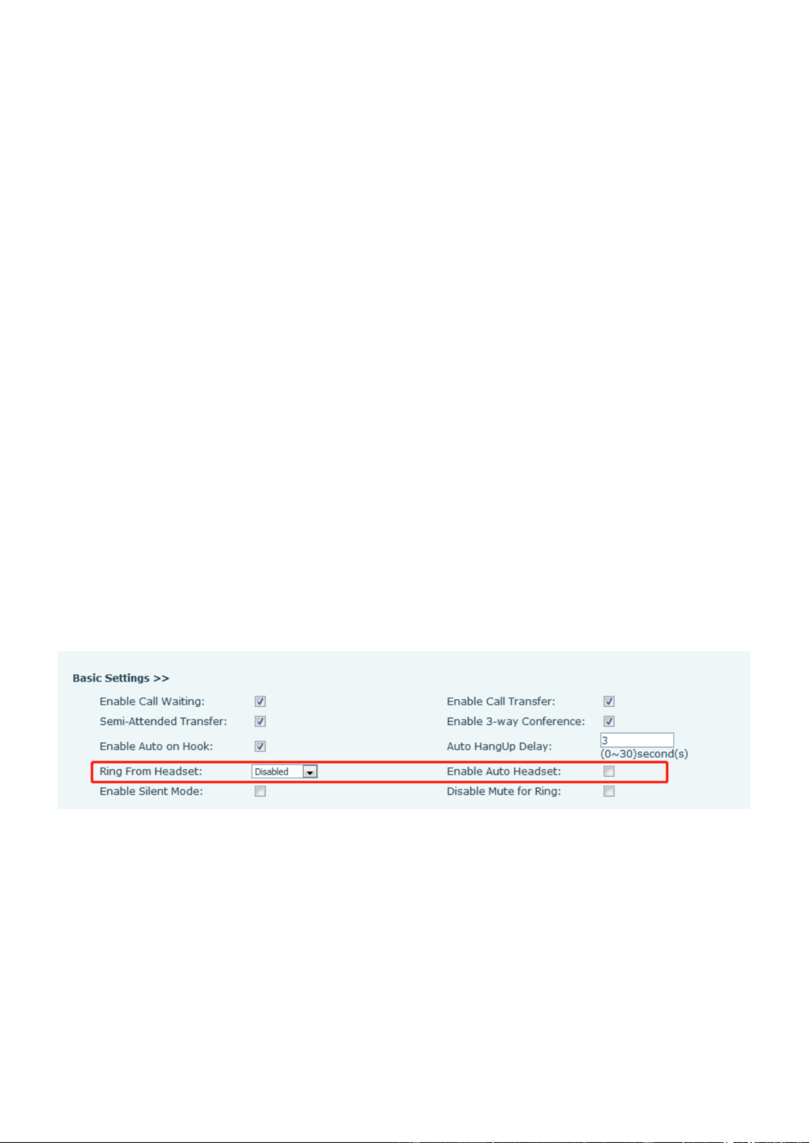
/ 12279
10.5 - Wi Fi
The device supports wireless Internet access and requires the use of a USB wi- adapter specied by
location;Therefore, the device needs to support U disk. When the device is in the default standby mode,
Press soft-button [Menu] till you nd the [Basic] item.
Press [WLAN] to enter the setting interface.
Select the wireless network and use the left and right keys to activate it. Enable the device to search the
current wireless network automatically.
Select to the available network, enter the user name and password to connect successfully.
Tip: if no wireless USB dongle is inserted, the prompt "wireless adapter has been removed" will appear.
If a USB dongle is plugged in, the wireless network will be priority network even if the network cable is
plugged in.
10.6 Headset
10.6.1 Wired Headset
The device supports wired earphone with RJ9 interface, which can play incoming call sound and talk with
earphone.
After the phone is connected to the headset, the default DSS key of headset will be green light which
indicating that the headset can be used normally.
On the webpage [Phone settings Features] >> [ ], you can set the headset answering function, and the
ring tone for headset.
Picture 106 - Headset function settings
10.6.2 EHS Headset
Phone into [Menu Function Advanced EHS Headset] [>> ] [>> ] Select [, ] can open EHS Headset (default ,
closed EHS Headset ).

/ 12280
Picture 107 - EHS Headset setting
10.6.3 Bluetooth Headset
The device supports bluetooth application and can be compatible with bluetooth headset with CSR 4.0 chip. It
needs to use USB bluetooth adapter specified by location.Therefore, the device needs to support U disk.
When the device is in the default standby mode,
Press soft-button [ till you find the [Menu] Basic] item.
Press [Bluetooth] to enter the setup interface.
Select Bluetooth, and use the left and right keys to enable Bluetooth. Select Paired Device. If no paired is
displayed, press [ key to search Scan] and select the scanned device to connect.
The use of Bluetooth headset can be divided into three types: call answering; Hang up; Bluetooth redial.
call answering
When the Bluetooth headset is connected to the phone, the incoming call can be answered by pressing the
Bluetooth answer button.
Hang up
1) When talking with Bluetooth headset, you can hang up the phone by pressing the button on Bluetooth
headset.
2) When there is an incoming call, double-click the answer button to reject the call.
3) When the caller is in the ringing state, press the answer button of the headset to cancel the call.
Bluetooth redial
When the Bluetooth headset is connected, double-click the answer button to redial the number dialed last
time.
NOTICE! some models do not support double - click redial function. Whether this function is
supported or not, you can check the instruction of the headset, or connect the Bluetooth headset to
the phone, and double-click the answer button to see whether it will redial.

/ 12281
10.7 Advanced
10.7.1 Line Congurations
Picture 108 - SIP address and account information
Save the adjustment by pressing [ when done. OK]
Users who want to configure more options should use web management portal to modify or Advanced
Settings in accounts on the individual line to congure those options.
Picture 109 - Congure Advanced Line Options
10.7.2 Network Settings
10.7.2.1 Network Settings
IP Mode
There are 3 network protocol mode options, IPv4, IPv6 and IPv4 & IPv6.
User could select available mode via “<” or “>”. The selected IP mode will be activated after pressing [OK]
button.
Picture 110 - Network mode Settings
IPv4

/ 12282
In IPv4 mode, there are 3 connection mode options: DHCP, PPPoE and Static IP.
Picture 111 - DHCP network mode
When using DHCP mode, phone will get the IP address from DHCP server (router).
Use DHCP DNS: It is enabled as default. “Enable” means phone will get DNS address from DHCP
server and “disable” means not.
Use DHCP time: It is disabled as default. “Enable” to manage the time of get DNS address from
DHCP server and “disable” means not.
Picture 112 - PPPoE network mode
When using PPPoE, phone will get the IP address from PPPoE server.
Username: PPPoE user name.
Password: PPPoE password.
Picture 113 - Static IP network mode
When using Static IP mode, user must congure the IP address manually.
IP Address Phone IP address. :
Mask: sub mask of your LAN.

/ 12283
Gateway: The gateway IP address. Phone could access the other network via it.
Primary Primary DNS address. The default is 8.8.8.8, Google DNS server address. DNS:
Secondary DNS: When primary DNS is not available, Secondary DNS will work.
IPv6
In IPv6, there are 2 connection mode options, DHCP and Static IP.
DHCP conguration refers to IPv4 introduction in last page.
Static IP configuration is almost same as IPv4’s, except the IPv6 Prefix.
IPv6 Prex IPv6 prex, it is similar with mask of IPv4. :
Picture 114 - IPv6 Static IP network mode
10.7.2.2 QoS & VLAN
LLDP
Link Layer Discovery Protocol. LLDP is a vendor independent link layer protocol used by network devices for
advertising their identity, capabilities to neighbors on a LAN segment.
Phone could use LLDP to nd the VLAN switch or other VLAN devices and use LLDP learn feature to apply
the VLAN ID from VLAN switch to phone its self.
CDP
Cisco Discovery Protocol. CDP is a not-for-profit charity that runs the global disclosure system for investors,
companies, cities, states and regions to manage their environmental impacts. According to the CDP, Cisco
devices could share the OS version, IP address, hardware version and so on.
Table - QoS & VLAN16
Parameters
Description
LLDP setting
Report
Enable LLDP
Interval
LLDP requests interval time
Learning
apply the learned VLAN ID to the phone configuration
QoS
QoS Mode
congure SIP DSCP and audio DSCP
WAN VLAN
WAN VLAN
WAN port VLAN conguration
LAN VLAN

/ 12284
LAN VLAN
LAN port VLAN conguration
CDP
CDP
CDP enable/disable CDP interval time ,
Note
:
:
:
::
QoS & VLAN details refer to
10.7.2.3 VPN
Virtual Private Network (VPN) is a technology to allow device to create a tunneling connection to a server and
becomes part of the server’s network. The network transmission of the device may be routed through the
VPN server.
For some users, especially enterprise users, a VPN connection might be required to be established before
activate a line registration. The device supports two VPN modes, Layer 2 Transportation Protocol (L2TP) and
OpenVPN.
The VPN connection must be configured and started (or stopped) from the device web portal.
L2TP
NOTICE! The device only supports non-encrypted basic authentication and non-encrypted data
tunneling. For users who need data encryption, please use OpenVPN instead.
To establish a L2TP connection, users should log in to the device web portal, open webpage [ Network] >>
[VPN]. In VPN Mode, check the “Enable VPN” option and select “L2TP”, then fill in the L2TP server address,
Authentication Username, and Authentication Password in the L2TP section. Press “Apply” then the device
will try to connect to the L2TP server.
When the VPN connection established, the VPN IP Address should be displayed in the VPN status. There
may be the delay of the connection establishment. User may need to refresh the page to update the status.
Once the VPN is congured, the device will try to connect with the VPN automatically when the device boots
up every time until user disable it. Sometimes, if the VPN connection does not establish immediately, user
may try to reboot the device and check if VPN connection established after reboot.
OpenVPN
To establish an OpenVPN connection, user should get the following authentication and conguration les
from the OpenVPN hosting provider and name them as the following,
OpenVPN Conguration le: client.ovpn
CA Root Certication: ca.crt
Client Certification: client.crt
Client Key: client.key
User then upload these les to the device in the web page [Network VPN] >> [ ], select OpenVPN Files. Then
user should check “Enable VPN” and select “OpenVPN” in VPN Mode and click “Apply” to enable OpenVPN
connection.
Same as L2TP connection, the connection will be established every time when system rebooted until user
disable it manually.
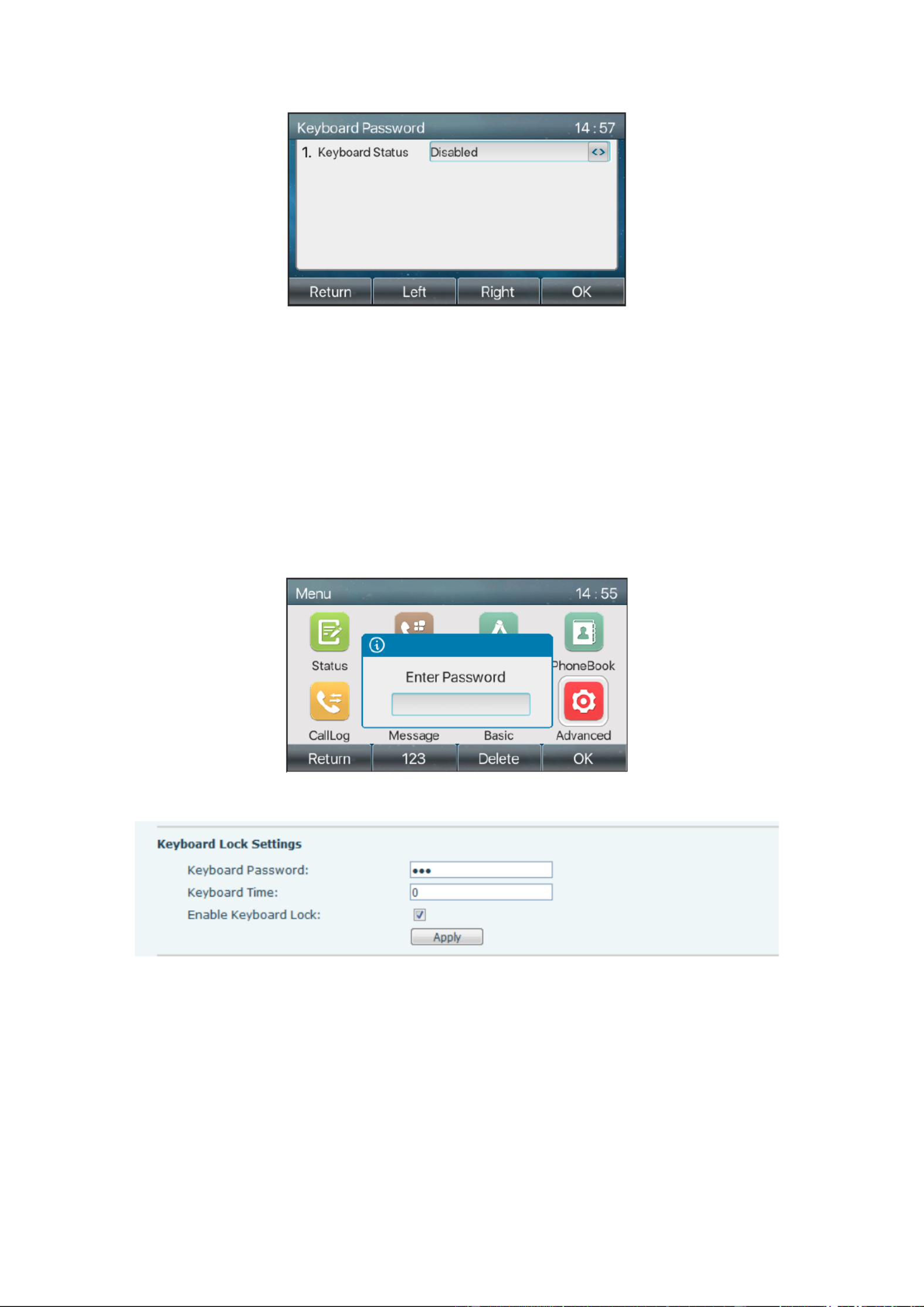
/ 12286
Picture 117 - Set keyboard lock password
User could only set to enable or disable the keyboard password in LCD screen.
Enter [Keyboard password] setting by pressing [conrm] or [OK] button after password entered. If no
menu password conguration before, it is 123 as default.
If the menu password is correct, phone will go to keyboard password interface. As default, the keyboard
password is disabled. When it is enabled, the keyboard will be locked after timeout.
If user does not configure the keyboard lock time, (it is 0 as default). Long pressing “#” will lock the phone.
There will be a lock icon in the top of LCD. Phone will reminder “Enter Password” after pressing any
keys.
Picture 118 - Phone keypad lock password input interface
Picture 119 - Web keyboard lock password Settin gs
10.7.4 Maintenance
Phone Webpage: Login and go to [System Auto provision] [>> ] .

/ 12287
Picture 120 - Page auto provision Settings
LCD [ ] [: Menu >> Advanced setting Maintenance Auto Provision] [>> ] [>> ].
Picture 121 - Phone auto provision settings
support SIP PnP, DHCP options, Static provision, TR069. If all of the 4 methods are enabled, the priority from
high to low as below:
PNP>DHCP>TR069> Static Provisioning
Transferring protocol: FTP, TFTP, HTTP, HTTPS
Tabl - Auto Provision e 17
Parameters
Description
Basic settings
CPE Serial Number
Display the device SN

/ 12288
Authentication Name
The user name of provision server
Authentication Password
The password of provision server
Conguration File
Encryption Key
If the device conguration le is encrypted , user should add the encryption
key here
General Conguration File
Encryption Key
If the common conguration le is encrypted, user should add the encryption
key here
Download Fail Check
Times
If there download is failed, phone will retry with the congured times.
Update Contact Interval
Phone will update the phonebook with the congured interval time. If it is 0,
the feature is disabled.
Save Auto Provision
Information
Save the HTTP/HTTPS/FTP user name and password. If the provision URL
is kept, the information will be kept.
Download Common
Cong enabled
Whether phone will download the common conguration le.
Enable Server Digest
When the feature is enable, if the conguration of server is changed, phone
will download and update.
DHCP Option
Option Value
Conugre DHCP option, DHCP option supports DHCP custom option |
DHCP option 66 | DHCP option 43, 3 methods to get the provision URL. The
default is Option 66.
Custom Option Value
Custom Option value is allowed from 128 to 254. The option value must be
same as server dene.
Enable DHCP Option 120
Use Option120 to get the SIP server address from DHCP server.
SIP Plug and Play (PnP)
Enable SIP PnP
Whether enable PnP or not. If PnP is enable, phone will send a SIP
SUBSCRIBE message with broadcast method. Any server can support the
feature will respond and send a Notify with URL to phone. Phone could get
the conguration le with the URL.
Server Address
Broadcast address. As default, it is 224.0.0.0.
Server Port
PnP port
Transport Protocol
PnP protocol, TCP or UDP.
Update Interval
PnP message interval.
Static Provisioning Server
Server Address
Provisioning server address. Support both IP address and domain address.
Conguration File Name
The conguration le name. If it is empty, phone will request the common le
and device le which is named as its MAC address.
The le name could be a common name, $mac.cfg, $input.cfg. The le
format supports CFG/TXT/XML.

/ 12289
Protocol Type
Transferring protocol type supports FTP TFTP HTTP and HTTPS , 、 、
Update Interval
Conguration le update interval time. As default it is 1, means phone will
check the update every 1 hour.
Update Mode
Provision Mode.
1. Disabled.
2. Update after reboot.
3. Update after interval.
TR069
Enable TR069
Enable TR069 after selection
ACS Server Type
There are 2 options Serve type, common and CTC.
ACS Server URL
ACS server address
ACS User
ACS server username (up to is 59 characte r)
ACS Password
ACS server password (up to is 59 character)
Enable TR069 Warning
Tone
If TR069 is enabled, there will be a prompt tone when connecting.
TLS Version
TLS version (TLS 1.0, TLS 1.1, TLS 1.2)
INFORM Sending Period
INFORM signal interval time. It ranges from 1s to 999s
STUN Server Address
Congure STUN server address
STUN Enable
To enable STUN server for TR069
10.7.5 Firmware Upgrade
Web page: Login phone web page, go to [System] >> [Upgrade].
Picture 122 - Web page rmware upgrade
LCD interface: go to [Menu Advanced setting Firmware Upgrade] [>> ] [>> ] .
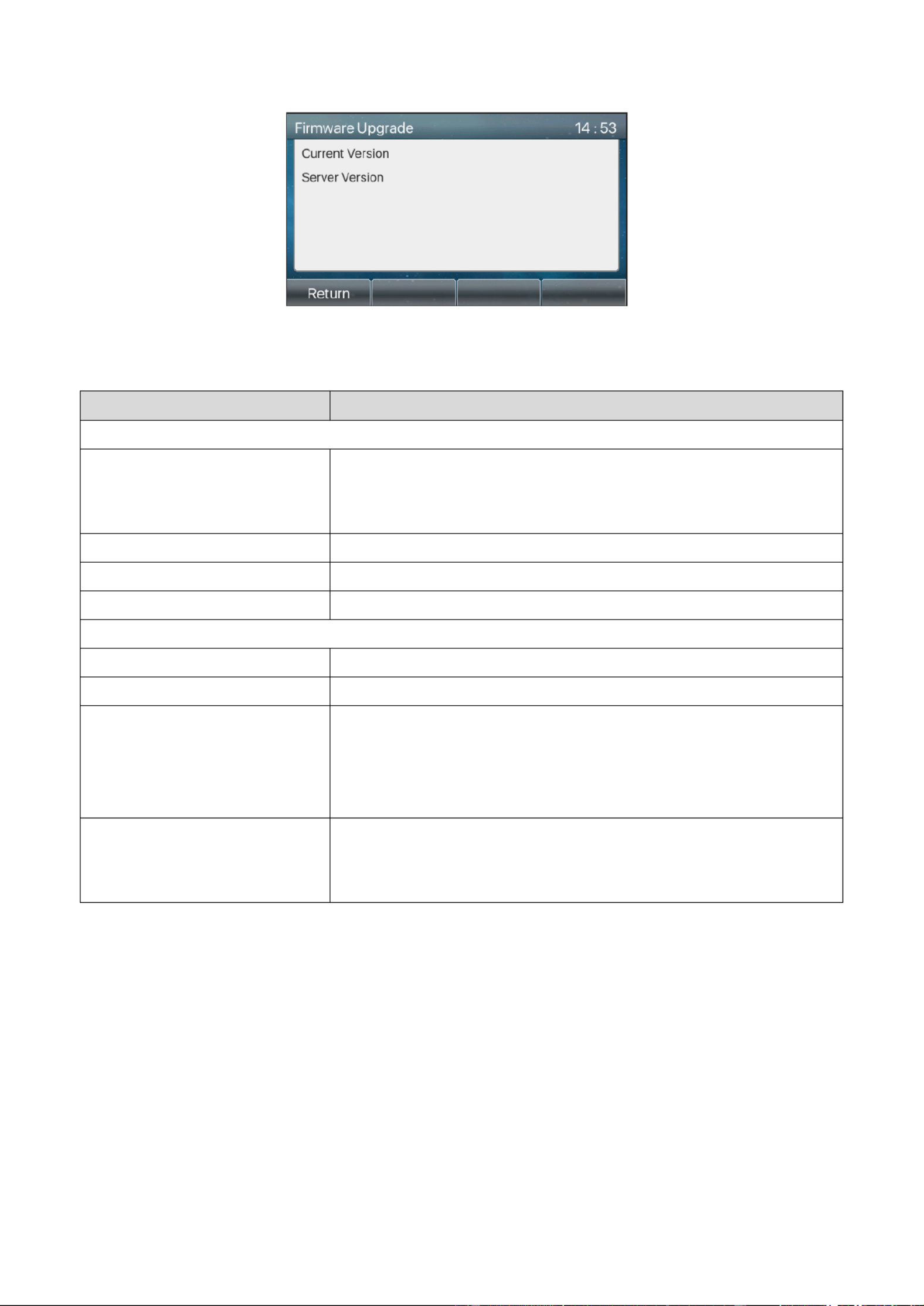
/ 12290
Picture 123 - Firmware upgrade information display
Table 18 - Firmware upgrade
Parameter
Description
Upgrade server
Enable Auto Upgrade
Enable automatic upgrade, If there is a new version txt and new
software rmware on the server, phone will show a prompt upgrade
message after Update Interval.
Upgrade Server Address1
Set available upgrade server address.
Upgrade Server Address2
Set available upgrade server address.
Update Interval
Set Update Interval.
Firmware Information
Current Software Version
It will show Current Software Version.
Server Firmware Version
It will show Server Firmware Version.
[Upgrade] button
If there is a new version txt and new software rmware on the server,
the page will display version information and upgrade button will
become available; Click [Upgrade] button to upgrade the new
rmware.
New version description
information
When there is a corresponding TXT le and version on the server
side, the TXT and version information will be displayed under the
new version description information.
The le requested from the server is a TXT le called vendor_model_hw10.txt.Hw followed by the
hardware version number, it will be written as hw10 if no difference on hardware. All Spaces in the
lename are replaced by underline.
The URL requested by the phone is HTTP:// server address/vendor_Model_hw10
.txt: The new version and the requested le should be placed in the download directory of the HTTP
server, as shown in the gure:
TXT le format must be UTF-8
vendor_model_hw10.TXT
Version=1.6.3 #Firmware

101 / 122
Enable RFC4475
Set to enable RFC4475.
Enable Strict UA Match
Enable strict UA matching.
Registration Failure Retry
Time
Set the registration failure retry time.
Local SIP Port
Modify the phone SIP port.
12.6 Line >> SIP Hotspot
Please refer to 9.9 SIP Hotspot.
12.7 Line >> Dial Plan
Picture 127 - Dial plan settings
Table - Phone 7 dialing methods 21
Parameters
Description
Press # to invoke dialing
The user dials the other party's number and then adds the # number
to dial out;
Dial Fixed Length
The number entered by the user is automatically dialed out when it
reaches a fixed length
Timeout dial
The system dials automatically after timeout
Press # to Do Blind Transfer
The user enters the number to be transferred and then presses the
"#" key to transfer the current call to a third party
Blind Transfer on Onhook
After the user enters the number, hang up the handle or turn off the
hands-free function to transfer the current call to a third party.
Attended Transfer on Onhook
Hang up the handle or press the hands-free button to realize the
function of attention-transfer, which can transfer the current call to a
third party.
Product specificaties
| Merk: | Hikvision |
| Categorie: | Intercomsysteem |
| Model: | DS-KP8200-HE1 |
Heb je hulp nodig?
Als je hulp nodig hebt met Hikvision DS-KP8200-HE1 stel dan hieronder een vraag en andere gebruikers zullen je antwoorden
Handleiding Intercomsysteem Hikvision

27 Maart 2025
27 Maart 2025
8 Augustus 2024
8 Augustus 2024
8 Augustus 2024
8 Augustus 2024
8 Augustus 2024
8 Augustus 2024
8 Augustus 2024
7 Augustus 2024
Handleiding Intercomsysteem
- Intercomsysteem Philips
- Intercomsysteem Panasonic
- Intercomsysteem Bticino
- Intercomsysteem Abus
- Intercomsysteem Acti
- Intercomsysteem Alcatel
- Intercomsysteem Alecto
- Intercomsysteem Axis
- Intercomsysteem Byron
- Intercomsysteem DIO
- Intercomsysteem Elro
- Intercomsysteem Estom
- Intercomsysteem Foscam
- Intercomsysteem Gira
- Intercomsysteem HQ
- Intercomsysteem Konig
- Intercomsysteem Marmitek
- Intercomsysteem Midland
- Intercomsysteem Monacor
- Intercomsysteem Rollei
- Intercomsysteem Siedle
- Intercomsysteem Silvercrest
- Intercomsysteem Smartwares
- Intercomsysteem Somfy
- Intercomsysteem Sygonix
- Intercomsysteem Toa
- Intercomsysteem Viking
- Intercomsysteem Becken
- Intercomsysteem Schwaiger
- Intercomsysteem Steren
- Intercomsysteem DoorBird
- Intercomsysteem EMOS
- Intercomsysteem Avidsen
- Intercomsysteem Comelit
- Intercomsysteem Extel
- Intercomsysteem M-e
- Intercomsysteem NuTone
- Intercomsysteem TCS
- Intercomsysteem Chacon
- Intercomsysteem Swann
- Intercomsysteem Valcom
- Intercomsysteem Fibaro
- Intercomsysteem GEV
- Intercomsysteem Planet
- Intercomsysteem Chamberlain
- Intercomsysteem DataVideo
- Intercomsysteem Dahua Technology
- Intercomsysteem Busch-Jaeger
- Intercomsysteem Russound
- Intercomsysteem Fanvil
- Intercomsysteem Aiphone
- Intercomsysteem Crestron
- Intercomsysteem ORNO
- Intercomsysteem Sonifex
- Intercomsysteem RTS
- Intercomsysteem Nortek
- Intercomsysteem Vimar
- Intercomsysteem ZKTeco
- Intercomsysteem Akuvox
- Intercomsysteem Bitron
- Intercomsysteem Hollyland
- Intercomsysteem Elcom
- Intercomsysteem Hanwha
- Intercomsysteem Leviton
- Intercomsysteem EtiamPro
- Intercomsysteem Pentatech
- Intercomsysteem Ritto
- Intercomsysteem Arenti
- Intercomsysteem Syscom
- Intercomsysteem Pentatron
- Intercomsysteem Vibell
- Intercomsysteem CyberData Systems
- Intercomsysteem COMMAX
- Intercomsysteem Bintec-elmeg
- Intercomsysteem Eartec
- Intercomsysteem Gewiss
- Intercomsysteem Seco-Larm
- Intercomsysteem Tador
- Intercomsysteem WHD
- Intercomsysteem Mobotix
- Intercomsysteem FlyingVoice
- Intercomsysteem Toucan
- Intercomsysteem 2N Telecommunications
- Intercomsysteem Louroe Electronics
Nieuwste handleidingen voor Intercomsysteem

27 Maart 2025
27 Maart 2025
27 Maart 2025
9 Maart 2025
20 Februari 2025
20 Februari 2025
20 Februari 2025
20 Februari 2025
5 Februari 2025
30 Januari 2025