CyberPower CP700PFCRM1U Handleiding
CyberPower
UPS
CP700PFCRM1U
Lees hieronder de 📖 handleiding in het Nederlandse voor CyberPower CP700PFCRM1U (2 pagina's) in de categorie UPS. Deze handleiding was nuttig voor 9 personen en werd door 2 gebruikers gemiddeld met 4.5 sterren beoordeeld
Pagina 1/2
YOUR ULTIMATE ALLY IN POWER
CP500PFCRM1U / CP700PFCRM1U
USER MANUAL
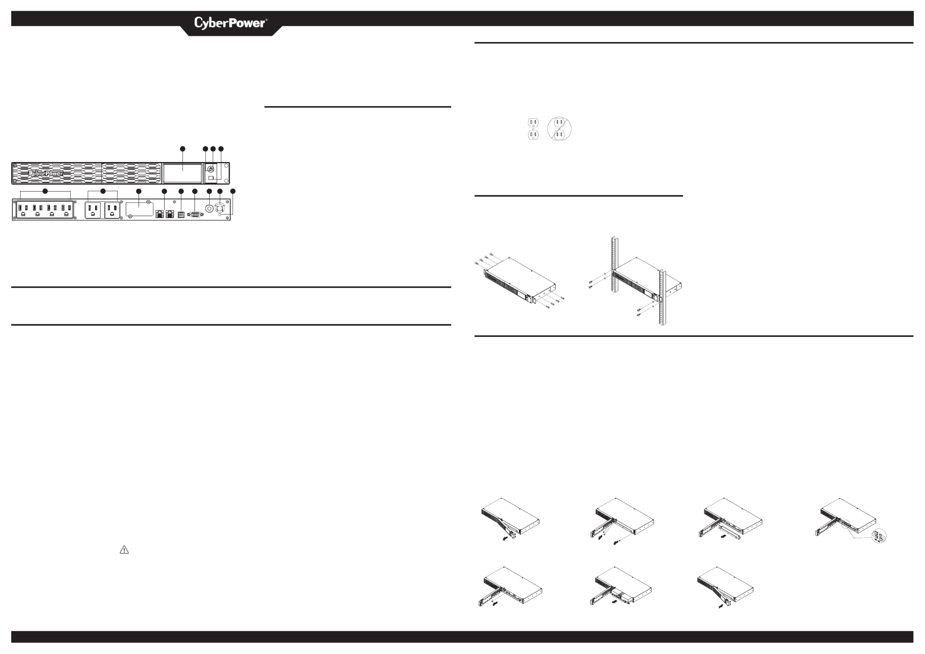
FEATURES
1 . LCD module display
2 . Power On Indicator
1 2 3 4 3 . Power Switch
4 . LCD Function Selected Switch
5 . Battery and Surge Protected Outlets
6 . Full-Time Surge Protection Outlets
5 6 7 8 9 10 11 12 13 7 . SNMP/HTTP Network Slot
8 . Communication Protection Ports RJ45
9 . USB Port to PC
10 . DB9 port
1 1 . Circuit Breaker
12 . AC Input
13 . Electrical Wiring Fault Indicator (Red)
PRODUCT REGISTRATION
Thank you for purchasing this CyberPower product. Please take a few minutes to register your product at: w.CyberP erSystems.com/Registration. ww ow
Registration certifies your product's warranty, confirms your ownership in the event of a product loss or theft and entitles you to free technical support. Register your product now to receive
the benefits of CyberPower ownership.
IMPORTANT SAFETY INSTRUCTIONS (SAVE THESE INSTRUCTIONS)
This manual contains important instructions that should be foll ed during installation ow
and maintenance of the UPS and batteries. Please read and follow all instructions
carefully during installation and operation of the unit. Read this manual thoroughly before
attempting to unpack, install, or operate.
CAUTION! To prevent the risk of fire or
electric shock, install in a temperature
and humidity controlled indoor area free
of conductive contaminants. (Please see
specifications for a eptable temperature cc
and humidity range).
CAUTION! To reduce the risk of electric
shock, do not rem e the c er. There are ov ov
no user serviceable parts inside except for
the battery.
CAUTION! Hazardous live parts inside can
be energized by the battery even when the
AC input p er is disconnected. ow
CAUTION! The UPS must be connected
to an AC p er outlet with fuse or circuit ow
breaker protection. Do not plug into an
outlet that is not grounded. If you need to
de-energize this equipment, turn o° and
unplug the unit.
CAUTION! To avoid electric shock, turn
o° the unit and unplug it from the AC
power source before installing a computer
component.
CAUTION! Not for use in a computer
room as defined in the Standard for the
Protection of Electronic Computer/Data
Processing Equipment, ANSI/NFPA 75.
CAUTION! To reduce the risk of fire,
connect only to a circuit provided with
20 amperes maximum branch circuit over
current protection in a ordance with the cc
National Electric Code, ANSI/NFPA . 70
CAUTION! For PLUGGABLE EQUIPMENT,
the socket-outlet shall be installed near the
equipment and shall be easily accessible.
DO NOT USE FOR LIFE SUPPORT
EQUIPMENT! CyberP er Systems does ow
not sell products for life support. DO NOT
use in any circumstance that would a°ect
operation and safety of life support
equipment.
CAUTION! DO NOT USE WITH OR NEAR
AQUARIUMS! To reduce the risk of fire or
electric shock, do not use with or near an
aquarium. Condensation from the aquarium
can cause the unit to short out.
CAUTION! DO NOT USE THE UPS ON ANY
TRANSPORTATION! To reduce the risk of
fire or electric shock, do not use the unit on
an ran ta uch a ay t spor tion s s irpl es an o h . r s ips
The e°ect of shock or vibration caused
during transit and the damp environment
can cause the unit to short out.
CAUTION! DO NOT USE WITH LASER
PRINTERS! The power demands of laser
printers are too large for a UPS.
CAUTION! To reduce the risk of electric
shock, do not remove the c er, except to ov
service the battery. There are no serviceable
parts inside, except for the battery.
WARNING: This product can expose
you to chemicals including Styrene, which
is known to the State of California to cause
cancer, and Bisphenol-A, which is known to
the State of California to cause birth defects
or other reproductive harm. For more
information, go to w.P65Warnings. .gov. ww ca
INSTALLING YOUR UPS SYSTEM
UNPACKING
Inspect the UPS upon receipt. The box
should contain the following:
(a) UPS unit
(b) User’s manual
(c) Rack mount brackets
(d) USB A+B type cable
*P erPanel® Business software is ow
available on our website. Please visit
CyberPowerSystems.com and go to the
Software Section for free download.
OVERVIEW
The CP500PFCRM1U / CP700PFCRM1U
provides automatic voltage regulation
to correct for inconsistent utility power.
The CP500PFCRM1U / CP700PFCRM1U
features 1150 Joules of surge protection,
and provides battery backup during
p er outages. The CP500PFCRM1U / ow
CP700PFCRM1U ensures consistent power
to your computer system and its included
software will automatically save your open
files and shutdown your computer system
during a utility power loss.
HOW TO DETERMINE THE POWER
REQUIREMENTS OF YOUR EQUIPMENT
1. Ensure that the equipment plugged into
the UPS does not exceed the UPS unit’s
rated capacity. If the rated capacities
of the unit are exceeded, an overload
condition may occur and cause the UPS
unit to shut down or the circuit breaker
to trip.
2. There are many factors that can
a°ect the amount of power that your
electronic equipment will require. For
optimal system performance keep the
load below 80% of the unit’s rated
capacity.
Cyber Power Systems (USA), Inc.
AUTOMATIC VOLTAGE REGULATOR
The CP500PFCRM1U/CP700PFCRM1U
stabilizes inconsistent utility power. The
incoming utility power may be damaging
to important data files, but with Automatic
Voltage Regulation, the computer will not
experience damaging voltage levels. An
Aut a Vom tic oltage Regulator aut aom ti llca y
increases low voltage to a consistent,
computer safe 110v/120v. The unit’s
p erful sealed lead-acid batteries will ow
provide p er only if the incoming voltage ow
drops below 100v.
HARDWARE INSTALLATION GUIDE
1. Your new UPS may be used immediately
upon receipt. However, after receiving
a new UPS, to ensure the battery’s
maximum charge capacity, it is
recommended that you charge the
battery for at least 8 hours. Your UPS is
equipped with an auto-charge feature.
When the UPS is plugged into an AC
outlet, the battery will automatically
charge whether the UPS is turned on or
turned o°.
2. If you will use the software, connect the
USB cable to the USB port on the UPS.
3. With the UPS unit turned o° and
unplugged, connect your computer,
monitor, and any other peripherals
requiring battery backup into the
battery power supplied outlets. Plug the
other peripheral equipment (e.g. printer,
scan r, speakers, etc.) into the full-time ne
surge protection outlets. DO NOT plug
a laser printer, paper shredder, copier,
space heater, vacuum cleaner, sump
pump, or other large electrical device
into the “Battery and Surge Protected
Outlets”. The p er demands of these ow
devices will erload and possibly ov
damage the unit.
INSTALLING YOUR UPS SYSTEM - Continued
HARDWARE INSTALLATION GUIDE
4. Plug the UPS into a 2 pole, 3 wire
grounded receptacle (wall outlet). Make
sure the wall branch outlet is protected
by a fuse or circuit breaker and does
not service equipment with large
electrical demands ( g. air conditioner, e.
refrigerator, copier, etc.). The warranty
prohibits the use of extension cords,
outlet strips, and
surge strips in
conjunction with
the UPS unit.
5. Press the power switch to turn the unit
on. The Power On indicator light will
illuminate green and the unit will “beep”
twice.
RACK INSTALLATION (OPTION)
6. If an overload is detected, an audible
alarm will sound and the unit will emit
one long beep. To correct this, turn the
UPS o° and unplug at least one piece
of equipment from the battery p er ow
supplied outlets. Make sure the circuit
breaker is depressed and then turn the
UPS on.
7. To maintain optimal battery charge,
leave the UPS plugged into an AC outlet
at all times.
8. To store the UPS for an extended period
of time, c er it and store with the ov
battery fully charged. While in storage,
rec rha ge t e bh attery ever hre months y t e
to ensure optimal battery life.
9. Ensure the wall outlet and UPS are
located near the equipment being
attached for proper accessibility.
1. Use the provided pan head screws to attach the hanging brackets to the UPS.
2. Use the provided truss head screws to secure the UPS to your existing rack system.
1. 2.
REPLACING THE BATTERY
Read and follow the important safety instructions before servicing the batteries. Visit
CyberPower o˛cial
website www.cyberpowersystems.com or contact your dealer for more information about
replacement batteries.
CAUTION! Read and follow the IMPORTANT SAFETY INSTRUCTIONS before servicing
the battery. Service the battery under the supervision of personnel knowledgeable of
batteries and their precautions.
CAUTION! When replacing batteries, replace with the same number of the following
battery: CyberP er/RB0670X2 for CP500PFCRM1U and CyberP er/ RB0690X2 for ow ow
CP700PFCRM1U. See your dealer for replacement batteries.
CAUTION! Risk of energy hazard, 12 V, 7 Ampere-hour battery for CP500PCFRM1U, 12V, 8
Ampere-hour battery for CP700PCFRM1U. Before replacing batteries, rem e conductive ov
jewelry such as chains, wrist watches and rings. High energy through conductive materials
could cause severe burns.
CAUTION! Risk of explosion if battery is replaced by an incorrect type. Dispose of used
batteries a ording to the instructions. cc
CA Th att ma rUTION! e b ery y p ese ct k. o n e o et th risk f el ric cal sho D n e o atte s ot dispos f b rie
in a fire, the batteries may explode. Follow all local ordinances regarding proper disposal
of batteries.
1. 2.
Remove the right-side of the faceplate. Remove the three retaining screws on
the cable protection cover.
5. 6.
Remove the retaining screw of the Replace the new battery pack.
battery tray.
BASIC OPERATION
1. LCD module display
LCD Screen shows all the UPS information
with icons and messages.
2. Power On Indicator
This LED is illuminated when the utility
condition is no al and the UPS outlets are rm
providing p er, free of surges and spikes. ow
3. Power Switch
Master on/o° switch for equipment
connected to the battery p er supplied ow
outlets.
4. LCD Function Selected Switch
The switch can be used to select the LCD
display contents Including input/output
voltage and estimated run time, etc.
5. Battery and Surge Protected Outlets
The unit has four battery powered/surge
protec tl ts r te ud o e fo c n te nt on ec d equipme
to ensure temporary uninterrupted
operation of your equipment during a
p er failure. (DO NOT plug a laser printer, ow
paper shredder, copier, space heater,
vacuum cleaner, sump pump or other
large electrical devices into the “Battery
and Surge Protected Outlets”. The p er ow
demands of these devices may erload ov
and damage the unit.)
6. Full-Time Surge Protection Outlets
The unit has two surge protected outlets.
7. SNMP/HTTP Network Slot
Rem e the c er panel to install an ov ov
optional RMCARD provides remote
monitoring and management of your UPS
over a network.
8. Communication Protection Ports RJ45
Communication protection ports, bi-
directional, will protect a 10/100/1000
ethernet connection. (RJ45).
*Not for telecommunication (telephone)
network.
9. USB Port to PC
This port allows connection and
communication from the USB port on
the computer to the UPS unit. The UPS
c icatommun es its statu tos the P erPa l® ow ne
Business software.
10. DB9 Port
This port is used for connecting between
the UPS and equipment designed to
operate with contact signals.
11. Circuit Breaker
Located on the back of the UPS, the circuit
breaker serves to provide overload and
fault protection. Under normal operating
conditions, the circuit breaker is depressed.
12. AC Input
Connect the AC Power cord to a properly
wired and grounded outlet.
13. Electrical Wiring Fault Indicator (Red)
This LED indicator will illuminate to warn
the user that a wiring problem exists,
such as a bad ground, missed ground
or reversed wiring. If this is illuminated,
disconnect all electrical equipment from
the outlet and have an electrician check
to ensure the outlet is properly wired.
The unit will not provide surge protection
without being plugged into a grounded
and properly wired wall outlet.
CAUTION! Do not open or mutilate batteries. Released material is harmful to the skin and eyes.
It may be toxic.
CAUTION! A battery can present a risk of electrical shock and high short-circuit current.
Contact with part of a grounded battery can result in electrical shock. The following
precautions should be observed when working on batteries:
1. Remove all watches, rings or other metal objects.
2. Only use tools with insulated handles.
3. lay tools or other metal parts on top of battery or any battery terminals. DO NOT
4. Wear rubber gloves and boots.
5. Determine if the battery is inadvertently grounded. If inadvertently grounded, rem e ov
source of ground.
CONTACT WITH A GROUNDED BATTERY CAN RESULT IN ELECTRICAL SHOCK! The
likelihood of such shock will be reduced if such grounds are removed during installation and
maintenance (applicable to a UPS and a remote battery supply not having a grounded circuit).
CAUTION! The used batteries are considered hazardous waste and must be disposed through
recycling.
Most retailers that sell lead-acid batteries collect used batteries for recycling, as required by
local regulations.
3. 4.
Remove the cable protective cover. Disconnect the black and red cables.
7.
Assemble the screws, cover, cable and front
panel in the reverse sequence of ab e steps. ov
Recharge the unit for 8 hours to ensure the UPS
performs expected runtime.
4241 12th Avenue East, Suite 400 | Shakopee, MN 55379 | CyberPowerSystems.com
K01-0001050-00

DEFINITIONS FOR ILLUMINATED LCD INDICATORS
1. ON LINE Icon
This icon illuminates when the UPS is working under normal conditions.
2. AVR (Automatic Voltage Regulation) Icon
This icon appears whenever your UPS is automatically correcting low AC line voltage
without using battery power. This is a normal, automatic operation of your UPS, and
no action is required on your part.
3. CURRENT LOAD Icon
LOAD capacity: This meter displays the approximate output load level (in 20%
increments) of the UPS battery outlets. Sensitivity setup: This meter is also used to
setup the UPS sensitivity when you are in the programming mode. If the connected
equipment can tolerate more power events (example: unstable power often associated
with stormy weather), select Low Sensitivity and the UPS will go to Battery Mode
less often. If the connected equipment is more sensitive to power events, select High
Sensitivity and the UPS will go to Battery Mode more often.
4. BATTERY CAPACITY Icon
This meter displays the approximate charge level (in 20% increments) of the UPS’s
internal battery. During a blackout or severe brownout, the UPS switches to battery
power, and the charge level will decrease.
5. ON BATT Icon
This icon will appear followed by an alarm (two short beeps) when there is a utility
power loss, indicating that the UPS is now working using its internal batteries. Once
the batteries are running out of power (over a period of time), the alarm will beep
rapidly every 1/2 second. If this happens and main power has not been restored, it is
recommended that you save your files and turn off your equipment manually as soon
as possible.
NOTE: If the ON BATT icon flashes, and the ON LINE icon appear simultaneously, this
indicates that the batteries are not connected properly or that the batteries are worn
out.
6. MUTE Icon
This icon appears when the UPS is in silent mode. However, when there is a problem
with the UPS, the alarm will still beep even in silent mode.
7. Input Voltage Meter
This meter measures the AC voltage from the wall outlet. The INPUT voltage readout
is used to identify the input voltage information. This can be used as a diagnostic tool
to identify the quality of input power.
8. Output Voltage Meter
This meter measures, in real time, the AC voltage that the UPS is providing to your
connected equipment via the UPS outlets.
9. RUNTIME
This displays how many minutes of runtime can be expected of the UPS if it were to
experience a power outage.
NOTE: The number displayed may be less than actual runtimes for low loads.
10. OVERLOAD Icon
This icon will appear followed by an alarm, indicating that an overload condition has
been reached. To recover from the overload condition, unplug equipment from the
UPS outlets until the icon disappears and the alarm stops.
11. FAULT
This icon appears if there is a problem with the UPS. Press the POWER button to turn
the UPS off.
E02: Charger Fault-No Charge (Contact CyberPower Systems for support.)
E11: Battery Overvoltage (Contact CyberPower Systems for support.)
E21: Output Short (Check the status of equipment connected to the UPS and then
turn on the UPS again.)
E22: Overload (Unplug at least one piece of equipment from battery outlets and turn
the UPS on again.)
Model CP500PFCRM1U CP700PFCRM1U
Capacity 500VA / 300W 700VA / 400W
Nominal Input Voltage 120Vac
Input Frequency 60 Hz ± 3 Hz
AVR Function Yes
On-Battery Output Voltage 120Vac ± 5%
*Under a test load of less than 60%. When the load exceeds 60%, the output voltage range may exceed 5%
On-Battery Output Wave Form Sine Wave
Size (W x H x D) 1U Rack, 433 x 44 x 229.7 (mm) / 17.05 x 1.73 x 9.04 (in)
Weight 17.97 lbs / 8.15 kg 18.30 lbs / 8.3 kg
Replacement Battery CyberPower / RB0670X2 CyberPower / RB0690X2
Typical Battery Recharge Time 8 hours
*Recover to 90% after full load discharge
Battery Type Sealed Maintenance Free Lead Acid Battery
Safety Approvals UL1778, FCC class B, DOE, Energy star1, CSA C22.2 No. 107.3
Operating Temperature 32°F – 104°F / 0°C – 40°C
Operating Relative Humidity 0% – 95% Non-condensing
Operating Elevation 0 – 9,843 feet / 0 – 3,000 meters
Storage Temperature 5°F – 113°F / -15°C – 45°C
Storage Relative Humidity 0% – 95% Non-condensing
Storage Elevation 0 – 49,213 feet / 0 – 15,000 meters
TROUBLESHOOTING
Problem Possible Cause Solution
Full-time surge protection outlets stop
providing power to equipment. Circuit breaker has tripped due to an overload. Turn the UPS off and unplug at least one piece of equipment. Wait 10 seconds,
reset the circuit breaker by depressing the button, and then turn the UPS on.
The UPS does not provide expected runtime.
Battery is not fully charged. Recharge the battery by leaving the UPS plugged in.
Battery is slightly worn out. Please contact CyberPower Systems about replacement batteries.
The on/off switch is designed to prevent damage
by rapidly turning it off and on. Turn the UPS off. Wait 10 seconds and then turn the UPS on.
The UPS will not turn on. The battery is worn out. Please contact CyberPower Systems about replacement batteries.
Mechanical problem. Please contact CyberPower Systems.
The USB cable is not connected. Connect the USB cable to the UPS unit and an open USB port on the the computer.
PowerPanel® Business Software is inactive.
(all icons are gray) The USB is connected to the wrong port. Check the computer for an additional USB. Move the cable to this port.
The unit is not providing battery power. Shutdown your computer and turn the UPS off. Wait 10 seconds and tu rn the UPS
on. This should reset the unit.
Additional troubleshooting information can be found under “Support” at CyberPowerSystems.com
SYSTEM FUNCTIONAL BLOCK DIAGRAM
Input Surge
Suppressor Output
AVR
Normal Mode
Battery Mode
TECHNICAL SPECIFICATIONS
1Battery recharges 48 hours to 100% capacity based on Energy Star efficiency test standard.
CYBERPOWER GREENPOWER UPS™ TECHNOLOGY
Advanced Energy-Saving Patented Bypass Technology
CyberPower’s patented GreenPower UPS™ with Bypass
Technology reduces UPS energy costs by up to 75% compared
to conventional UPS models. Even when utility power is normal,
conventional UPS models constantly pass power through a
transformer. By contrast, under normal conditions the advanced
circuitry of a GreenPower UPS™ bypasses the transformer. As
a result, the power efficiency is significantly increased while
decreasing waste heat, using less energy, and reducing energy
GREEN
POWER UPS™
Energy-Saving Technology
costs.
When an abnormal power condition occurs, the GreenPower UPS™
automatically runs power through its transformer to regulate
voltage and provide “safe” power. Since utility power is normal over 88% of the time, the
GreenPower UPS™ operates primarily in its efficient bypass mode.
The GreenPower UPS™ is also manufactured in accordance with the Restriction on
Hazardous Substances (RoHS) directive making it one of the most environmentally-friendly
on the market today.
FCC COMPLIANCE STATEMENT
This device complies with part 15 of the FCC rules. Operation is subject to the
following two conditions: (1) this device may not cause harmful interference,
and (2) this device must accept any interference received, including
interference that may cause undesired operation.
Note: This equipment has been tested and found to comply with the limits for a Class B
digital device, pursuant to part 15 of the FCC Rules. These limits are designed to provide
reasonable protection against harmful interference in a residential installation. This
equipment generates, uses, and can radiate radio frequency energy and, if not installed
and used in accordance with the instructions, may cause harmful interference to radio
communications. However, there is no guarantee that interference will not occur in a
particular installation. If this equipment does cause harmful interference to radio or
television reception, which can be determined by turning the equipment off and on, the user
is encouraged to try to correct the interference by one or more of the following measures:
- Reorient or relocate the receiving antenna.
- Increase the separation between the equipment and receiver.
- Connect the equipment to an outlet on a circuit different from that to which the receiver
is connected.
- Consult the dealer or an experienced radio/TV technician for help.
Warning: Changes or modifications not expressly approved by the party responsible for
compliance could void the user's authority to operate the equipment.
Canadian Compliance Statement
CAN ICES-003(B)/NMB-003(B)
DISPOSAL
The Waste Electrical and Electronic Equipment (WEEE) Directive aims to
contribute to sustainable production and consumption by contributing to
the efficient use of resources and the retrieval of secondary raw materials
through re-use, recycling and other forms of recovery. The symbol on this
product and/or its packaging indicates that the product must be disposed
of separately from ordinary household wastes at its end of life. Contact your
related WEEE management authority, local office, or your household waste
disposal service about information on the recycling drop off site.
BATTERY DISPOSAL
This product contains non-spillable lead acid batteries. The used
batteries are considered hazardous waste and must be disposed
through recycling. Do not dispose of used batteries with your
ordinary household wastes. Dispose of the batteries according to
the local regulations.
Note: Most retailers that sell lead-acid batteries collect used
batteries for recycling, as required by the local regulations.
LIMITED WARRANTY AND CONNECTED EQUIPMENT GUARANTEE
Please visit www.CyberPowerSystems.com for a copy of the Limited Warranty and
Connected Equipment Guarantee.
Where Can I Get More Information?
The application of the United Nations Convention of Contracts for the International Sale of
Goods is expressly excluded. CyberPower is the warrantor under this Limited Warranty.
For further information please feel free to contact CyberPower at:
Cyber Power Systems (USA), Inc. 4241 12th Ave E., STE 400, Shakopee, MN 55379;
call us at (877) 297-6937;
or submit a web ticket online at cyberpowersystems.com/support.
Cyber Power Systems (USA), Inc. encourages environmentally sound methods for disposal
and recycling of its UPS products. Please dispose and/or recycle your UPS and batteries in
accordance to the local regulations of your state.
WARNING: This product can expose you to chemicals including bisphenol A (BPA) and
styrene, which is known to the State of California to cause reproductive harm and cancer.
For more information, go to www.P65Warnings.ca.gov.
© 2024 Cyber Power Systems (USA), Inc. CyberPower®, the CyberPower logo and
PowerPanel® are registered trademarks of Cyber Power Systems (USA), Inc. All rights
reserved. All other trademarks used are property of their respective owners.
Charger
AC / DC Battery Inverter
Product specificaties
| Merk: | CyberPower |
| Categorie: | UPS |
| Model: | CP700PFCRM1U |
Heb je hulp nodig?
Als je hulp nodig hebt met CyberPower CP700PFCRM1U stel dan hieronder een vraag en andere gebruikers zullen je antwoorden
Handleiding UPS CyberPower

28 Januari 2025
28 Januari 2025
28 Januari 2025
28 Januari 2025
27 Januari 2025
27 Januari 2025
15 Januari 2025
8 December 2024
8 December 2024
15 November 2024
Handleiding UPS
- UPS HP
- UPS IKEA
- UPS AEG
- UPS Siemens
- UPS Apc
- UPS Dell
- UPS Digitus
- UPS Eaton
- UPS Emerson
- UPS Furman
- UPS Gembird
- UPS Gys
- UPS Hikvision
- UPS Lenovo
- UPS LevelOne
- UPS Riello
- UPS Schneider
- UPS Teltonika
- UPS Voltcraft
- UPS Jung
- UPS Steren
- UPS Conceptronic
- UPS Tripp Lite
- UPS Approx
- UPS Block
- UPS LC-Power
- UPS Energenie
- UPS Adj
- UPS East
- UPS Xtreme
- UPS Equip
- UPS Liebert
- UPS Avocent
- UPS Minute Man
- UPS Minuteman
- UPS Maruson
- UPS V7
- UPS Phoenix Contact
- UPS Puls Dimension
- UPS Vanson
- UPS Salicru
- UPS SurgeX
- UPS Murr Elektronik
- UPS Altronix
- UPS Ditek
- UPS Bxterra
- UPS Middle Atlantic
- UPS FSP
- UPS Atlantis Land
- UPS PowerWalker
- UPS FSP/Fortron
- UPS Online USV
Nieuwste handleidingen voor UPS
29 Maart 2025
29 Maart 2025

29 Maart 2025
28 Maart 2025
27 Maart 2025
27 Maart 2025
27 Maart 2025
27 Maart 2025
27 Maart 2025
27 Maart 2025