Bartscher 2953031 Handleiding
Bartscher
Pastamachine
2953031
Lees hieronder de 📖 handleiding in het Nederlandse voor Bartscher 2953031 (138 pagina's) in de categorie Pastamachine. Deze handleiding was nuttig voor 70 personen en werd door 2 gebruikers gemiddeld met 4.5 sterren beoordeeld
Pagina 1/138

GAS-NUDELKOCHER
GAS PASTA COOKER
CUISEUR À PÂTES À GAZ
CUOCIPASTA A GAS
COCEDOR DE PASTA GAS
MÁQUINA DE MACARRÃO, GAS
GAZ PASTAKOKER
URZĄDZENIE DO GOTOWANIA
PRODUKTÓW MĄCZNYCH, GAZOWE
Rev.-Nr.: 01-2017
INST ALLAT I ONS-, BEDI E NUNGS-
UND W AR T UNGSANW EISUNG E N
INST ALLAT I ON, OPERAT I NG
AND M AINTENANCE NST R UCTIONS
MANUEL D'INSTALLAT ION,
D'UT ILISATION ET D 'ENTRE T IEN
MANUALE DI INSTALLAZI ONE,
USO E MA NUTENZIONE
MANUAL DE INSTALACIÓN,
USO Y MA NT ENIMIENTO
MANUAL DE INSTALAÇÃ O,
UT ILIZA ÇÃO E MANU T ENÇÃO
HANDLEI D I NG VOOR I NST ALLAT I E,
GEBRUIK E N ONDERH OUD
WSKA ZÓW KI DOT YCZ CE I NSTALACJI, Ą
U YT KOW ANIA I K ONSERW AC JI Ż
2953031 / CPG91M01-IL
DE
GB
FR
IT
ES
PT
NL
PL

TECHNISCHE ÄNDERUNGEN VORBEHALTEN!
TECHNICAL CHANGES RESERVED!
SOUS RÉSERVE DE MODIFICATIONS TECHNIQUES !
CI RISERVIAMO LA POSSIBILITÀ DI INTRODURRE MODIFICHE TECNICHE!
¡SE RESERVA EL DERECHO A INTRODUCIR MODIFICACIONES TÉCNICAS!
SUJEITO A ALTERAÇÕES TÉCNICAS!
TECHNISCHE WIJZIGINGEN VOORBEHOUDEN!
WPROWADZANIE ZMIAN TECHNICZNYCH ZASTRZE ONE! Ż
PL
IT
DE
PT
NL
ES
FR
GB

1
DEUTSCH
DE
1. INHALTSVERZEICHNIS
1. INHALTSVERZEICHNIS .................................................................................................................... 1
2. SACHREGISTER ............................................................................................................................... 2
3. SICHERHEIT ...................................................................................................................................... 3
4. ALLGEMEINE BESTIMMUNGEN UND WARNHINWEISE ............................................................... 4
4.1. Allgemeine Hinweise ................................................................................................................ 4
4.2. Gerätebeschreibung ................................................................................................................. 4
4.3. Sicherheitseinrichtungen .......................................................................................................... 5
4.4. Typenschild .............................................................................................................................. 6
4.5. Austausch von Bauteilen (Servicetechniker) ........................................................................... 6
5. GEBRAUCH UND FUNKTION ........................................................................................................... 7
5.1. Beschreibung der Bedienung. .................................................................................................. 7
5.2. Brennerzündung ....................................................................................................................... 7
5.3. Füllen des Beckens .................................................................................................................. 8
5.4. Entleeren des Beckens ............................................................................................................ 8
5.5. Tipps zum Gebrauch ................................................................................................................ 8
6. REINIGUNG UND WARTUNG ........................................................................................................... 9
6.1. Hinweise zu Reinigung und Wartung ....................................................................................... 9
6.2. Ordentliche Wartung ................................................................................................................ 9
7. DEFEKTE ......................................................................................................................................... 10
8. INSTALLATION ................................................................................................................................ 10
8.1. Verpackung und Auspacken .................................................................................................. 10
8.2. Installation (Servicetechniker) ................................................................................................ 11
8.3. Wasseranschluss (Servicetechniker) ..................................................................................... 11
8.4. Gasanschluss (Servicetechniker) ........................................................................................... 12
8.5. Ableitung der Verbrennungsprodukte (Servicetechniker) ...................................................... 12
8.6. Montage des Geräts in Reihe ................................................................................................ 13
8.7. Umrüstung Versorgung (Servicetechniker) ............................................................................ 13
8.8. Prüfung (Servicetechniker) ..................................................................................................... 13
9. EINSTELLUNGEN ............................................................................................................................ 14
9.1. Minimum-Einstellung des Brennerhahns (Servicetechniker) ................................................. 14
9.2. Austausch Brennerdüse (Servicetechniker) ........................................................................... 14
9.3. Austausch Zündflammendüse Brenner (Servicetechniker) ................................................... 15
10. ENTSORUNG DES GERÄTS .......................................................................................................... 15
ANLAGEN ................................................................................................................................................. I

2
DEUTSCH
DE
2. SACHREGISTER
A
Ableitung der Verbrennungsprodukte 12
Allgemeine Hinweise 4
Auspacken 10
Austausch Brennerdüse 14
Austausch von Bauteilen 6
Austausch Zündflammendüse Brenner 15
B
Beschreibung der Bedienung 7
Brennerzündung 7
D
DEFEKTE 10
E
Entleeren des Beckens 8
ENTSORUNG DES GERÄTS 15
F
Füllen des Beckens 8
G
Gasanschluss 12
Gerätebeschreibung 4
H
Hinweise zu Reinigung und Wartung 9
I
Installation 11
M
Minimum-Einstellung des Brennerhahns 14
Montage des Geräts in Reihe 13
O
Ordentliche Wartung 9
P
Prüfung 13
S
SICHERHEIT 3
Sicherheitseinrichtungen 5
T
Tipps zum Gebrauch 8
Typenschild 6
U
Umrüstung Versorgung 13
V
Verpackung 10
W
Wasseranschluss 11

3
DEUTSCH
DE
3. SICHERHEIT
Vor Gebrauch des Gerätes die in
der vorliegenden Anleitung enthaltenen
Anweisungen und Warnungen
aufmerksam durchlesen.
Die Anleitung enthält grundlegende Informationen
zur Gebrauchssicherheit und Wartung des Geräts.
Bewahren Sie diese Anleitung sorgfältig auf,
damit Sie bei Bedarf stets nachlesen können.
Der Hersteller hat bei Entwurf und Herstellung
besondere Sorgfalt darauf verwendet, Gefahren
für die Sicherheit und Gesundheit von Personen
durch den Umgang mit dem Gerät zu vermeiden.
Lesen Sie aufmerksam die in der mitgelieferten
Anleitung angegebenen Anweisungen sowie die
direkt am Gerät angebrachten Hinweise, beachten
Sie insbesondere alle die Sicherheit betreffenden
Anweisungen.
Die installierten Sicherheitsvorrichtungen dürfen
weder manipuliert noch entfernt werden. Die
Nichtbeachtung dieser Anforderung kann zu
schweren Gefahren für die Sicherheit und
Gesundheit von Personen führen.
Führen Sie, auch nachdem Sie sich angemessen
informiert haben, beim erstmaligen Gebrauch,
wenn nötig, einige Testvorgänge durch, um die
Anordnung und Hauptfunktionen der
Bedienelemente, besonders zum Ein- und
Ausschalten, kennen zu lernen.
Das Gerät ist nur für den Gebrauch bestimmt, für
den es entworfen wurde; jeder andere Gebrauch
ist als unsachgemäß anzusehen.
Der Hersteller lehnt jede Haftung für Schäden an
Sachen oder Personen ab, die durch
unsachgemäßen oder fehlerhaften Gebrauch
verursacht werden.
Alle Wartungsarbeiten, die eine bestimmte
technische Qualifikation oder besondere
Fähigkeiten erfordern, dürfen ausschließlich durch
qualifiziertes Personal ausgeführt werden.
Um die Hygiene zu gewährleisten und die
Lebensmittel vor Verunreinigung zu schützen,
müssen alle Elemente, die direkt oder indirekt mit
den Lebensmitteln in Kontakt kommen, sowie alle
angrenzenden Bereiche sorgfältig gereinigt
werden. Hierzu sollten ausschließlich Reiniger für
den Lebensmittelbereich verwendet werden,
vermeiden Sie den Gebrauch entzündlicher oder
gesundheitsschädlicher Mittel.
Vergewissern Sie sich nach jedem
Gebrauch, dass die Brenner ausgeschaltet,
die Bedienelemente deaktiviert und die
Versorgungsleitungen abgetrennt sind.
Bei längerer Nichtbenutzung müssen nicht nur
alle Versorgungsleitungen abgetrennt, sondern
auch alle inneren und äußeren Teile des Gerätes
sorgfältig gereinigt werden.
Das Gerät darf nicht mit direktem
Wasserstahl gereinigt werden.

8
DEUTSCH
DE
5.3. Füllen des Beckens
Drehen Sie das Wasserventil, um das Becken bis
zum gewünschten Füllstand zu füllen. Nachdem
der Höchststand erreicht ist, kann der Brenner
gezündet werden.
Nach dem Füllen des Beckens muss das
Wasserventil geschlossen werden, um ein
gefährliches Überlaufen zu vermeiden.
Sinkt der Wasserstand unter das Minimum, muss
der Hahn wieder geöffnet werden.
Das Gerät kann an Warmwasser
angeschlossen werden, um die Aufheizzeit zu
reduzieren (max. 60 °C).
Wenn das Wasserniveau unter das
Auflagegitter der Körbe sinkt, könnte der
Sicherheitsthermostat eingreifen: Das Becken
mindestens bis zum Mindestniveau auffüllen
und dann erneut den Brenner einschalten.
Vermeiden Sie den Gebrauch des
Geräts mit einem Wasserstand unter dem
am Becken markierten Minimum.
5.4. Entleeren des Beckens
Das Ablaufwasser ist über einen geeigneten
Sammelbehälter abzuleiten, der für Temperaturen
von mindestens 100 °C beständig ist.
Zum Entleeren des Wassers aus dem Becken den
Ablasshahn nach unten drehen. A
Prüfen Sie vor dem Füllen des
Beckens, ob der Ablasshahn A
geschlossen ist.
5.5. Tipps zum Gebrauch
Bleibt das Gerät für eine längere Zeit unbenutzt,
gehen Sie wie folgt vor:
1. Schließen Sie den Gas-Absperrhahn;
2. Reinigen Sie sorgfältig das Gerät und die
angrenzenden Bereiche;
3. Tragen Sie auf die Edelstahlflächen einen
Film aus Vaselineöl auf;
4. Führen Sie alle Wartungsarbeiten durch;
5. Lassen Sie das Gerät unbedeckt und die
Kochkammern geöffnet.
Entleeren Sie nach Gebrauch stets
das Becken.
Um einen ordnungsgemäßen Gebrauch des
Gerätes zu gewährleisten, sollten Sie folgendes
beachten:
Verwenden Sie ausschließlich das vom
Hersteller angegebene Zubehör;
Verwenden Sie die Kochkörbe auf
angemessene Weise;
Prüfen Sie vor dem Füllen des Beckens, ob
der Ablasshahn geschlossen ist;
Vergewissern Sie sich, dass der Wasserstand
niemals unter das auf dem Becken markierte
Minimum sinkt.
Verwenden Sie das Gerät niemals
ohne Wasser im Becken. Dies kann zu
irreparablen Schäden am Gerät führen.
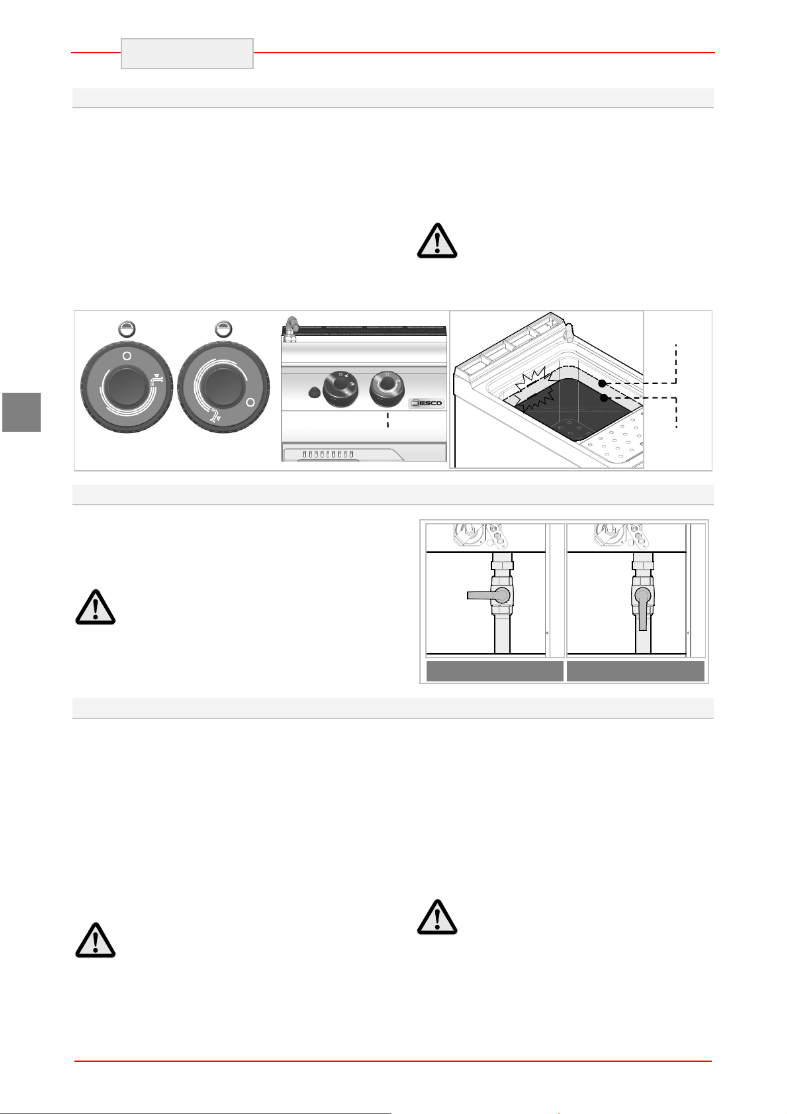
Hahn GESCHLOSSEN
ID
05
A
Hahn GEÖFFNET
Pos 0
Pos 1
Höchst-
stand
Mindest-
stand

9
DEUTSCH
DE
6. REINIGUNG UND WARTUNG
6.1. Hinweise zu Reinigung und Wartung
Aktivieren Sie alle vorhandenen
Sicherheitsvorrichtungen, bevor Sie
Wartungsarbeiten ausführen.
Schließen Sie insbesondere den Gas-
Absperrhahn und verhindern Sie den
Zugang zu Vorrichtungen, die, wenn sie
aktiviert werden, unerwartete
Gefahrensituationen für die Sicherheit und
Gesundheit von Personen auslösen
können.
6.2. Ordentliche Wartung
Die ordentliche Wartung besteht in der täglichen
Reinigung aller Teile, die mit Lebensmitteln in
Kontakt kommen können, und der regelmäßigen
Wartung der Brenner, der Düsen und der
Abflussleitungen.
Eine sorgfältige Wartung ermöglicht das Erreichen
der besten Leistungen, eine längere
Betriebsdauer und eine Konstanthaltung der
Sicherheitsanforderungen.
Keine direkten Wasserstrahlen oder Hochdruck-
reiniger auf das Gerät richten.
Verwenden Sie zur Reinigung des rostfreien
Stahls keine Eisenwolle, -bürsten oder -schaber,
da diese Eisenpartikel zurücklassen können, die
durch Oxidation zu Rostbildung führen.
Verwenden Sie zum Entfernen von
angetrockneten Rückständen Spateln aus Holz
oder Kunststoff oder weiche Scheuerschwämme.
Tragen Sie während Zeiten langer Nichtbenutzung
mit einem in Vaselinöl getränkten Lappen auf alle
Edelstahlflächen eine Schutzschicht auf und lüften
Sie die Räume regelmäßig.
Verwenden Sie keine Reiniger, die
gefährliche oder gesundheitsschädliche
Stoffe enthalten (Lösungsmittel, Benzin
usw.).
Lassen Sie regelmäßig die folgenden Wartungen
durch spezialisiertes Personal ausführen:
Kontrolle des Drucks und der Dichtigkeit der
Anlage;
Prüfung der Funktionstüchtigkeit der
Thermoelemente;
Prüfung der einwandfreien Funktion des
Abzugs und eventuelle Reinigung;
Prüfung und eventuelle Schmierung der
Gashähne.
Prüfung des korrekten Betriebs des
Sicherheitsdruckwächters.

10
DEUTSCH
DE
7. DEFEKTE
Die folgenden Informationen dienen der
Erkennung und Behebung eventueller
Funktionsstörungen, die während des Betriebs
auftreten könnten. Einige dieser Probleme können
vom Benutzer gelöst werden, für alle anderen ist
eine genaue Fachkenntnis erforderlich, sie dürfen
daher ausschließlich durch qualifiziertes Personal
behoben werden.
Problem Ursachen Lösungsmöglichkeiten
Gasgeruch. Gelegentliches Entweichen
durch Erlöschen der Flamme.
Gas-Absperrhahn schließen und
Raum belüften.
Die Zündflamme entzündet
sich nicht.
Die Funken-Zündvorrichtung
funktioniert nicht Funktionstüchtigkeit der
Zündvorrichtungen prüfen.
Zündflamme von Hand anzünden.
Kundendienst kontaktieren.
Luft in den Rohrleitungen nach
langer Nichtbenutzung.
Die Zündflamme geht immer
wieder aus.
Das Thermoelement ist nicht
heiß genug. Den Anzündvorgang verlängern.
Die Flamme ist gelb. Der Brenner ist verschmutzt
oder nass.
Brenner reinigen und trocknen
lassen.
Wenn das Problem weiter
besteht, Kundendienst kontaktieren.
Der Brenner-Regler lässt
sich schwer drehen. Fehlfunktion des Hahns. Kundendienst kontaktieren.
8. INSTALLATION
8.1. Verpackung und Auspacken
Beachten Sie beim Handling und bei der
Installation die Herstellerinformationen, die direkt
auf der Verpackung, auf dem Gerät und in der
vorliegenden Anleitung angegeben sind.
Zum Heben und Transportieren des Produkts ist
der Einsatz eines Gabelstaplers oder Hubwagens
vorgesehen, wobei besonders auf die
gleichmäßige Gewichtsverteilung zu achten ist,
um die Gefahr des Umkippens zu vermeiden
(vermeiden Sie übermäßige Neigungen!).
Achten Sie beim Einsetzen der
Hebevorrichtung auf den Gasversorgungs-
schlauch und auf die Position der
Standfüße.
Die Verpackung besteht aus Karton und der
Holzpalette. Auf der Kartonverpackung ist eine
Reihe von Symbolen aufgedruckt, die,
entsprechend den internationalen Bestimmungen,
auf die Vorschriften hinweisen, die beim Laden
und Entladen, Transport und Lagerung der Geräte
einzuhalten sind.
Prüfen Sie beim Empfang, dass die Verpackung
vollständig ist und während des Transports nicht
beschädigt wurde.
Eventuelle Beschädigungen sind unverzüglich
beim Transporteur zu beanstanden.
HIER
OBEN
VORSICHT
GLAS
VOR
FEUCHTIGKEIT
SCHÜTZEN

11
DEUTSCH
DE
Packen Sie das Gerät sobald wie möglich aus, um
zu prüfen, ob es unversehrt und unbeschädigt ist.
Ritzen Sie die Kartonverpackung nicht mit
scharfen Schneidwerkzeugen ein. Dies kann zu
Beschädigungen der darunter liegenden
Edelstahlbleche führen.
Ziehen Sie die Kartonverpackung nach oben vom
Gerät ab.
Prüfen Sie nach dem Auspacken, ob die
Ausstattung des Geräts mit Ihrer Bestellung
übereinstimmt.
Verständigen Sie im Fall von Unregelmäßigkeiten
unverzüglich den Händler.
Lagern Sie das Verpackungsmaterial
(Nylonbeutel, Styropor, Klammern ...) nicht
in der Reichweite von Kindern!
Entfernen Sie den PVC-Schutzfilm von den Innen-
und Außenwänden. Benutzen Sie hierfür
möglichst keine Metallwerkzeuge.
8.2. Installation (Servicetechniker)
Alle Installationsphasen sind von Beginn der
Projektumsetzung an zu bedenken.
Der Aufstellungsort muss mit sämtlichen
Versorgungsanschlüssen sowie dem Abfluss für
Produktionsrückstände ausgerüstet und
angemessen beleuchtet sein und über alle
Hygiene- und sanitären Voraussetzungen
entsprechend den geltenden Gesetzen verfügen.
Die Installation muss in einem Abstand von der
Wand von mindestens 5 cm erfolgen, wenn diese
nicht bis mindestens 150 °C temperaturbeständig
ist.
Richten Sie das Gerät durch Einstellen der
einzelnen Standfüße horizontal aus.
Um einen einwandfreien Betrieb
des Geräts zu gewährleisten, darf
dieses nur in permanent belüfteten
Räumen installiert und betrieben
werden.
Die interne Gasversorgungsanlage und die
Räume, in denen das Gerät aufgestellt wird,
müssen den geltenden Bestimmungen des
Verwendungslandes entsprechen (Ministerial-
verordnung vom 12. Juli '96 und UNI-CIG 87/23).
Es ist die für eine regelmäßige Verbrennung des
Gases an den Brennern erforderliche Luftmenge
zuzuführen, d. h. ca. 2 Kubikmeter pro Stunde für
jedes kW der installierten Leistung.
8.3. Wasseranschluss (Servicetechniker)
Der Anschluss erfolgt durch Verbinden des
Anschlussschlauchs des Geräts mit dem Rohr
des Wasserversorgungsnetzes. An der
Verbindung ist ein Absperrhahn (A) zu
installieren, um die Wasserversorgung bei Bedarf
unterbrechen zu können. Hinter diesem sind
einfach zu erreichende Filter zu installieren.
Das Gerät muss mit Trinkwasser
versorgt werden. In der Tabelle sind die
von der Europäischen Gemeinschaft
festgelegten Grenzwerte für Trinkwasser
zusammengefasst.
Beschreibung Wert
Druck 150-300 kPA
1.5-3 bar
pH 6.5-8
Härte 8-15°F
(80-150 ppm CaCO3)
fester Rückstand <1500 mg/L
Eisen < 0.2 mg/L
Mangan <0.05 mg/L
Chloride <0.25 mg/L
Sulfate <0.25 mg/L
ID 12
ID
06

12
DEUTSCH
DE
8.4. Gasanschluss (Servicetechniker)
Der Gasanschluss muss entsprechend der
geltenden Bestimmungen erfolgen.
Überprüfen Sie vor dem Anschluss des Geräts die
technischen Daten, die Gasart, den Betriebsdruck
und die Durchflussmenge, die auf dem
Typenschild angegeben sind.
Der Anschluss erfolgt durch Verbinden des
Anschlussschlauchs des Geräts mit dem Rohr
des Gasversorgungsnetzes. An der Verbindung
ist ein Absperrhahn zu installieren, um die
Gasversorgung bei Bedarf unterbrechen zu
können.
Falls in der Gasversorgungsanlage erhebliche
Druckschwankungen auftreten, wird der Einsatz
eines Druckreglers empfohlen.
Prüfen Sie nach dem Anschluss auf eventuelle
Gaslecks.
Niemals offene Flammen für die
Suche nach Gaslecks verwenden!
8.5. Ableitung der Verbrennungsprodukte (Servicetechniker)
Für die Installation von Geräten vom Typ " " ist A
kein Anschluss an eine Rauchabzugsanlage
vorgesehen, sondern eine geeignete
Abzugshaube mit sicherer Wirkung, so dass die
Verbrennungsprodukte nach außen abgeführt
werden.
Installation unter Abzugshaube (A).
Positionieren Sie das Gerät unter der Haube ( )1
und setzen Sie am Abluftanschluss des Geräts
ein Rohr mit den in der Abbildung angegebenen
Abmessungen an.
Das Ende der Abluftleitung muss sich mindestens
1,8 Meter über der Aufstellebene des Geräts
befinden.
Die Gasversorgung des Geräts
muss dem Zwangsableitungssystem direkt
untergeordnet sein: Eine Blockierung des
Abluftgebläses muss die Unterbrechung
der Gasversorgung auslösen.
Das Gebläse der Abzugsanlage
muss automatisch anlaufen, wenn der
Gasversorgungshahn geöffnet wird.
ID
08

13
DEUTSCH
DE
8.6. Montage des Geräts in Reihe
Um die Geräte in Reihe (Seite an Seite) zu
montieren, gehen Sie wie angegeben vor.
Montieren Sie die Bedientafeln ab und entfernen
Sie wenn nötig den Abluftgrill.
Verwenden Sie auf den aneinander stoßenden
Seitenteilen Dichtband ( ). A
Schieben Sie die Geräte nebeneinander und
richten Sie sie horizontal aus (durch Einstellen der
Standfüße).
Verbinden Sie die Geräte mit den
Befestigungselementen.
8.7. Umrüstung Versorgung (Servicetechniker)
Das Gerät wurde vom Hersteller mit dem auf dem
Typenschild angegebenen Gas geprüft. Soll eine
andere Gasart verwendet werden, ist wie folgt
vorzugehen.
1. ASchließen Sie den Gas-Absperrhahn ( ).
2. Ersetzen Sie die Brennerdüse (siehe
besonderes Kapitel).
3. Ersetzen Sie die Düse der Zündflamme (siehe
besonderes Kapitel).
4. Stellen Sie das Minimum am Gashahn des
Brenners ein (siehe besonderes Kapitel).
5. Regeln Sie, wenn erforderlich, die
Primärluftzufuhr des Brenners.
6. Entfernen Sie den auf dem Typenschild
angebrachten Aufkleber und bringen Sie den
neuen an, auf dem das verwendete Gas
angegeben ist (Position 4 des Typenschildes).
8.8. Prüfung (Servicetechniker)
Vor der Inbetriebnahme ist eine Prüfung der
Anlage vorzunehmen, um die
Betriebsbedingungen jedes einzelnen Bauteils zu
beurteilen und eventuelle Unregelmäßigkeiten zu
erkennen.
Führen Sie für die Prüfung folgende Kontrollen
durch:
1. Öffnen sie den Gasversorgungshahn und
prüfen Sie die Dichtigkeit der Verbindungen;
2. Prüfen Sie, ob der Brenner einwandfrei zündet
und verbrennt;
3. Prüfen und regeln Sie, wenn nötig, Gasdruck
und -durchflussmenge bei Minimum und
Maximum (siehe besonderes Kapitel)
4. Prüfen Sie, ob das Sicherheitsthermoelement
einwandfrei funktioniert;
5. Prüfen Sie die Gasanschlüsse auf Gaslecks.
A
A
B
C
C
ID 12

14
DEUTSCH
DE
9. EINSTELLUNGEN
Aktivieren Sie alle vorhandenen
Sicherheitsvorrichtungen, bevor Sie eine
Einstellung vornehmen.
Schließen Sie insbesondere den Gashahn
und verhindern Sie den Zugang zu
Vorrichtungen, die, wenn sie aktiviert
werden, unerwartete Gefahrensituationen
für die Sicherheit und Gesundheit von
Personen auslösen können.
9.1. Minimum-Einstellung des Brennerhahns (Servicetechniker)
Diese Einstellung ist nur vorzunehmen, wenn die
anzuschließende Gasart von der Prüfgasart
abweicht, nachdem die Versorgungsumrüstung
vorgenommen wurde. Vor der Ausführung dieser
Einstellung ist zu prüfen, ob der Gasdruck mit
dem Wert des der Gasart entsprechenden
Nenndrucks übereinstimmt (siehe beigefügte
Tabelle).
Gehen Sie hierzu auf die angegebene Weise vor.
1. Schließen Sie den Gas-Absperrhahn.
2. AZiehen Sie Reglerknopf ab.
3. BSchrauben Sie die Schrauben heraus
und nehmen Sie das Bedienfeld ( ) ab. C
4. DZiehen Sie Injektor heraus und
ersetzen Sie ihn durch einen, der für die
Art des verwendeten Gases geeignet ist
(siehe Anlagen). Versiegeln Sie die
Schraube nach der Einstellung mit Lack.
5. Montieren Sie am Ende das Bedienfeld
( ) und den Reglerknopf ( ). C A
9.2. Austausch Brennerdüse (Servicetechniker)
Gehen Sie hierzu auf die angegebene Weise vor.
Schließen Sie den Gas-Absperrhahn
Öffnen Sie die Klappe ( ). A
Ersetzen Sie die Düse ( ) durch eine, die für B
die Art des verwendeten Gases geeignet ist
(siehe Anlagen).
Lösen Sie Schraube und stellen Sie die C
Stellung des Venturi-Rohrs ( ) ein. D
Stellen Sie am Ende den Anfangszustand
wieder her.
Schließen Sie die Klappe.
H
A
ID
16
B
D
C
D
C
A
B
ID
09
ID
13

15
DEUTSCH
DE
9.3. Austausch Zündflammendüse Brenner (Servicetechniker)
Gehen Sie hierzu auf die angegebene Weise vor.
Schließen Sie den Gas-Absperrhahn.
Öffnen Sie die Klappe ( ). A
Die Zündflamme ist neben dem Brenner
angeordnet.
Schrauben Sie die Kappe ( ) ab. B
Ziehen Sie Düse heraus und ersetzen Sie C
sie durch eine, die für die Art des
verwendeten Gases geeignet ist (siehe
beiliegende Tabellen).
Setzen Sie die Kappe wieder auf und stellen
Sie den Anfangszustand wieder her.
Schließen Sie die Klappe.
10. ENTSORUNG DES GERÄTS
Dieses Gerät ist entsprechend der
Europäischen Richtlinie 2002/96/EG, WASTE
ELECTRICAL AND ELECTRONIC
EQUIPMENT (WEEE), gekennzeichnet.
Wenn Sie sicherstellen, dass dieses
Produkt ordnungsgemäß entsorgt wird,
leisten Sie einen Beitrag zur Vorbeugung
von möglichen negativen Folgen für
Umwelt und Gesundheit.
Das Symbol auf dem Produkt oder auf
der Begleitdokumentation weist darauf hin, dass
dieses Produkt nicht wie normaler Hausmüll
behandelt werden darf, sondern der
entsprechenden Sammelstelle zum Recycling von
Elektro- und Elektronik-Geräten zugeführt werden
muss.
Beachten Sie die örtlichen Bestimmungen zur
Abfallentsorgung.
Weitere Informationen zu Behandlung,
Wiederverwertung und Recycling dieses Produkts
erhalten Sie bei der zuständigen örtlichen
Behörde, dem Abfallentsorgungsdienst oder dem
Händler, bei dem Sie das Produkt erworben
haben.
A
B
C


1
ENGLISH
GB
1. TABLE OF CONTENTS
1. TABLE OF CONTENTS ..................................................................................................................... 1
2. INDEX ................................................................................................................................................. 2
3. SAFETY .............................................................................................................................................. 3
4. GENERAL INFORMATION AND WARNINGS ................................................................................... 4
4.1. General guidelines ................................................................................................................... 4
4.2. Description of the appliance ..................................................................................................... 4
4.3. Protection appliances ............................................................................................................... 5
4.4. Rating plate .............................................................................................................................. 6
4.5. Replacement of components (service technician) ................................................................... 6
5. USE AND OPERATION ..................................................................................................................... 7
5.1. Description of the controls . ...................................................................................................... 7
5.2. Burner ignition .......................................................................................................................... 7
5.3. Filling the tank .......................................................................................................................... 8
5.4. Draining the container .............................................................................................................. 8
5.5. Guidelines on how to use ......................................................................................................... 8
6. CLEANING AND MAINTENANCE ..................................................................................................... 8
6.1. Guidelines on cleaning and maintenance ................................................................................ 8
6.2. Proper maintenance ................................................................................................................. 9
7. TROUBLESHOOTING ..................................................................................................................... 10
8. INSTALLATION ................................................................................................................................ 10
8.1. Packaging and unpacking ...................................................................................................... 10
8.2. Installation (service technician) .............................................................................................. 11
8.3. Water connection (service technician) ................................................................................... 11
8.4. Gas connection (service technician) ...................................................................................... 12
8.5. Extraction of fumes (service technician) ................................................................................ 12
8.6. Installation of the appliance in a line ...................................................................................... 13
8.7. Gas supply (service technician) ............................................................................................. 13
8.8. Inspection (service technician) ............................................................................................... 13
9. SETTINGS ........................................................................................................................................ 14
9.1. Minimum setting of burner valve (service technician) ............................................................ 14
9.2. Replacement of burner nozzle (service technician) ............................................................... 14
9.3. Replacement of igniting flame burner nozzle (service technician) ......................................... 15
10. APPLIANCE DISPOSAL .................................................................................................................. 15
ATTACHMENTS ....................................................................................................................................... I

2
ENGLISH
GB
2. INDEX
A
APPLIANCE DISPOSAL 15
B
Burner ignition 7
D
Description of the appliance 4
Description of the controls 7
Draining the container 8
E
Extraction of fumes 12
F
Filling the tank 8
G
Gas connection 12
Gas supply 13
General guidelines 4
Guidelines on cleaning and maintenance 8
Guidelines on how to use 8
I
Inspection 13
Installation 11
Installation of the appliance in a line 13
M
Minimum setting of the heating plate burner
valve. 14
P
Packaging 10
Proper maintenance 9
Protection appliances 5
R
Rating plate 6
Replacement of burner nozzle 14
Replacement of components 6
Replacement of igniting flame burner nozzle 15
S
SAFETY 3
T
TROUBLESHOOTING 10
U
Unpacking 10
W
Water connection 11

3
ENGLISH
GB
3. SAFETY
Read carefully the guidelines and
instructions in the instruction manual
before you use the appliance.
The instruction manual contains general
information on how to safely use and maintain the
appliance.
Retain the manual for future reference.
The manufacturer took extra care when designing
and manufacturing to prevent any safety or health
hazard to the personnel operating the appliance.
Please read carefully the guidelines in the
instruction manual and instructions placed directly
onto the appliance. Above all, observe all the
safety instructions.
Do not intervene in or remove the protective
appliances installed in the appliance. Non-
compliance may lead to severe safety and health
hazard against people. We recommend to perform
a few tests to know the layout and main functions
of the control panel, particularly those to switch
the appliance on and off.
The appliance is intended only for the use it has
been designed for and any other use is
considered as the use not in compliance with the
intended use.
The manufacturer is not liable for material
damage or damage to person caused by
misapplication or incorrect application of the
appliance.
Any maintenance work that requires special
technical licence or special skills may be
performed by qualified personnel only.
To provide hygiene and protect foods from dirt, all
the elements that have direct or indirect contact
with the foods and all border areas must be
thoroughly cleaned. Use only the cleaning agents
intended for use in contact with food and avoid
using flammable agents or harmful to health.
After each use make sure that the
burner is switched off, the operational
elements are deactivated, and the gas
supply hoses are disconnected.
When the device will not be used for a longer time
not only disconnect all gas supply hoses, but also
thoroughly clean all internal and external elements
of the device.
You must not clean the appliance
with the direct stream of water.

4
ENGLISH
GB
4. GENERAL INFORMATION AND WARNINGS
4.1. General guidelines
The manual has been edited by the manufacturer
to provide the authorized personnel with the
information necessary to work with the appliance.
We recommend the intended readers to read the
manual carefully and comply with the information.
By reading the information contained in the
manual, hazards against people health and safety
may be prevented.
Retain the manual in an easily available place
throughout the time of use of the appliance to
have access and refer to the required information
at any time.
Special symbols, described below, have been
used to stress important information or draw
attention to essential data:
Caution - warning
Indicate important safety
instructions. You should acquire the
proper conduct to prevent hazard against
people health and safety or not to cause
any damage.
Important
Indicate essentials technical data that
you cannot ignore.
4.2. Description of the appliance
This appliance, called pasta cooker, has been
designed and manufactured for professional
gastronomy for cooking flour food products in
water.
1) Container
2) Door
3) Feet of adjustable height
4) Gas connection
5) Extractor: Extraction of combustion gases
6) Water valve: Fills and adjusts water
amount in the container.
7) Power control knob: adjusts burner power
(min - max)
8) Burner ignition: piezoelectric burner
ignition
9) Water inlet: fills container with water:
10) Minimum and maximum water level in the
container.
1
2
3
4
5
7
6
ID 01
8
9
10

5
ENGLISH
GB
4.3. Protection appliances
The appliance is equipped with the protection
system. The arrangement of protection appliances
is presented on the drawing.
A) Gas cut-off valve: to open and close the gas
line.
B) Safety thermocouple: cuts off the gas supply
if the flame goes out.
C) Safety thermostat: cuts off gas supply when
there is no water.
Check every day that the protection
appliances are mounted correctly and
operational.
After releasing of the safety thermostat restore the
initial settings of the appliance.
1. Wait for the unit to cool.
2. DOpen the door ( ).
3. Press the safety thermostat button (B) to
reactivate the gas supply.
4. DClose the door ( ).
After releasing of the safety thermostat
press button ( ).C
B
C
A
C
D

6
ENGLISH
GB
4.4. Rating plate
The rating plate indicated in the drawing is
mounted directly onto the appliance. There are all
guidelines and information on the plate required
for safe use.
1) EAN number
2) Code no./ Model no. / CE certificate no.
3) Category of appliance / type of design
4) Connected value / gas consumption /
adjusted to gas type
5) Thermal load
6) Production date
7) Series no.
8) WEEE symbol
9) CE Declaration of Conformity
4.5. Replacement of components (service technician)
Before exchange of the component
switch on all the existing protection
appliances.
First of all, switch off the gas valve and
prevent access to the appliance, which in
the case of activation may lead to
unexpected situations endangering the
safety and health of people.
If necessary, exchange the used components to
the original spare parts.
We are not liable for personal injury or
damage to the components that arise due to
application of other spare parts than original
or intervention into the appliance without the
manufacturer’s consent that may have altered
the safety requirements.
1
2
3
4
5
6
7
8
9

7
ENGLISH
GB
5. USE AND OPERATION
5.1. Description of the controls .
The elements controlling the essential functions
are located on the control panel of the appliance.
A) Burner control knob: for igniting, putting
out, and adjusting the main burner.
B) Water valve: for filling the tank.
C) Piezoelectric ignition: for starting the
igniting flame of the burner.
5.2. Burner ignition
IGNITION
A) Press the burner control knob and rotate it
counter clockwise (position ); at the 1
same time press button to start the B
igniting flame.
B) Hold the control knob B pressed for
approx. 10 seconds in order to heat up
the thermal element; then release the
controller.
C) To ignite the burner rotate the control
knob clockwise (position 2).
D) Set the burner power (position 3).
SWITCHING OFF
A) To switch off the burner rotate the control
knob clockwise (position the igniting 1);
flame is still on.
B) To switch off the igniting flame rotate the
control knob clockwise (position 0).
Pos 1
Pos 2
Pos 3
Pos 0
22S
22R
B
Minimum
power symbol
Water valve
Piezoelectric
ignition
A
B
C
Maximum
power symbol
Flame icon

8
ENGLISH
GB
5.3. Filling the tank
Rotate the water valve to fill the tank to the
required level. After reaching the maximum level
the burner may be ignited.
After filling close the water valve to avoid
dangerous overfilling.
When water level drops below minimum open the
water valve again.
The appliance may be connected to hot water
supply to reduce the heating time (max. 60°C).
When the water level drops below the
basket bottom, the safety thermostat may trip:
Fill the tank at least to the minimum level and
reignite the burner.
Avoid using the appliance with the
tank filled below the marked minimum
level.
5.4. Draining the container
Water may be drained with use of appropriate
container resistant to temperature of min. 100°C.
To drain the tank rotate the drain valve down. A
Before filling up the container
check that the outlet valve A is closed.
5.5. Guidelines on how to use
When the appliance will not be used for a longer
time, follow the instructions below:
1. Close the gas cut-off valve.
2. Thoroughly clean the appliance and adjacent
surfaces.
3. Apply the food grade vaseline on the stainless
steel surfaces.
4. Perform all maintenance works.
5. Leave the appliance uncovered, with opened
cooking chambers.
Always empty the containers
after use.
To ensure correct use of the appliance follow the
guidelines below:
Use only accessories provided by the
manufacturer;
Use baskets in the correct way;
Before filling the tank check if the drain valve
is closed;
Make sure that the water level is above the
minimum level marked in the tank.
Never use the appliance without
water in the tank. It may cause total
damage of the appliance.
CLOSED valve
ID 05
A
OPENED valve
Pos. 0
Pos. 1
Maximum
level
Minimum
level

9
ENGLISH
GB
6. CLEANING AND MAINTENANCE
6.1. Guidelines on cleaning and maintenance
Before you start maintenance
works, turn on all the mounted protective
appliances.
First of all, close the gas valve and
prevent access to the appliance, which in
the case of activation may lead to
unexpected situations endangering the
safety and health of people.
6.2. Proper maintenance
Proper maintenance includes daily cleaning of all
components which have contact with food
products, and regular maintenance of the burner,
nozzle and exhaust pipes.
Thorough maintenance allows for obtaining the
best results, assures longer life of the appliance,
and keeping constant level of the safety
requirements.
Never direct the water stream or high pressure jet
towards the appliance.
To clean the stainless steel, do not use iron wool
or iron brush as they may leave iron particles on
the surface that form rust in result of oxidation.
Use the wooden or plastic spatula, or soft
cleaning sponge to remove the dried remains.
When the appliance will not be used for a longer
time, use cloth soaked in food grade vaseline to
apply the protective layer on all stainless steel
surfaces and ventilate the room periodically.
Do not use any clearing agents that
contain substances hazardous or harmful
to health (solvents, petrol. etc.).
Regularly instruct the specialist personnel to
perform the following maintenance works:
Installation pressure and tightness control;
Thermocouples functionality control;
Control of operation of the extractor and
possible cleaning;
Inspection and possible lubrication of gas
valves.
Control of correct operation of safety barostat.

10
ENGLISH
GB
7. TROUBLESHOOTING
The information below is provided to recognize
and repair any failures that may occur when
operating the appliance.
Some of the failures can be repaired by the user,
others require thorough specialist knowledge.
Such problems may be solved exclusively by the
qualified personnel.
Problem Cause Solution
Gas smell.
The smell is sometimes
released when extinguishing
the flame.
Close the gas cut-off valve and
ventilate the room.
The ignition flame does not start.
The spark ignition does not
work. Check operation of ignition
appliances. Ignite the flame
manually.
Contact the service company.
Air in the pipes in connection
with the long downtime.
The igniting flame continuously
goes out.
The thermal element is not
sufficiently hot. Extend the ignition process.
Yellow flame. The burner is contaminated or
moist.
Clean the burner and leave for
drying.
When problem persists contact
the service company.
It is difficult to rotate the burner
control knob. Damaged valve.
Contact the service company.
8. INSTALLATION
8.1. Packaging and unpacking
During unloading and when installing the
appliance follow the information from the
manufacturer placed directly on the packaging
and in this manual.
To lift and transport the product plan to use a fork
lift or stacker, and pay attention to even weight
distribution to avoid a risk of tilting of the
packaging (avoid excessive incline!).
While using the elevator pay
attention to the gas supply hoses and
position of feet.
The packaging consists of the carton packaging
and wooden pallet. There are symbols printed on
the carton packaging that according to the
international agreements inform about the
regulations to follow when loading and unloading,
transporting and storing the appliance.
When collecting the goods check if the packaging
is complete and has not been damaged during
transport.
Any damage should be immediately reported to
the shipping company.
THIS
SIDE UP
CAUTION
GLASS
KEEP DRY

11
ENGLISH
GB
Unpack the appliance as soon as possible to
check if the appliance is not damaged.
Do not use a sharp object to cut the carton box. It
may damage the stainless steel inside the box.
Remove the carton packaging from bottom to top.
When unpacked check if the appliance is
according to the order.
In case of any difference inform the sales agent
immediately.
Do not store the packaging
materials (nylon bags, polystyrene foam,
clips ...) in the reach of children!
Remove the protective PVC layer from the out
and inner surfaces. If possible, do not use any
metal tools.
8.2. Installation (service technician)
All the stages of the installation must be carefully
planned.
The location should be equipped with all supply
connections and production waste outlet. The
location should also be properly lit and comply
with all hygiene and sanitary requirements
according to the binding regulations.
The appliance should be installed with the
minimum 5 cm clearance from the wall, if the
wall is not resistant to the minimum temperature
of 150 °C.
Locate the appliance in the horizontal position by
adjusting the single feet.
To ensure the correct operation of
the appliance, the appliance must be
installed and operated in the thoroughly
ventilated room only.
Internal installation of the gas supply and the
rooms in which the appliance is housed, must
comply with the local regulations applicable in the
country in which the appliance is used (Regulation
of 12 June 96 and UNI-CIG 87/23).
In order to ensure the proper gas burning in the
burners the required volume of air, i.e. approx.
2 cubic meters per hour for every kW of installed
power, must be supplied.
8.3. Water connection (service technician)
The installation is performed by connecting the
connection pipe of the appliance to the water
network pipe. Install the cut-off valve (A) on the
connection to stop the water supply when
required. Install appropriate filters after that valve.
Connect potable water to the
appliance. Limit values for the potable
water specified by the European Union are
listed in the table.
Description Value
Pressure 150-300 kPA
1.5-3 bar
pH 6.5-8
Hardness 8-15°F
(80-150 ppm CaCO3)
Minerals <1500 mg/l
Iron < 0.2 mg/l
Manganese <0.05 mg/l
Chlorine <0.25 mg/l
Sulphur <0.25 mg/l
ID
12
ID
06

12
ENGLISH
GB
8.4. Gas connection (service technician)
A gas connection must be performed in
compliance with the applicable regulations.
Before connecting the appliance, check the
technical data, type of gas, working pressure and
flow rate which are provided on the rating plate.
The installation is performed by connecting the
connection pipe of the appliance with a pipe of the
gas distribution network. A shut-off valve must be
installed on the connection to shut the gas supply
off if necessary.
If there are significant pressure differences in the
gas supply installation, it is recommended to
install a pressure regulator.
After the installation, check the gas connection for
tightness.
When looking for gas leaks do not
use the open flame!
8.5. Extraction of fumes (service technician)
Installation of the type “A” appliances does not
envisage connection to the fume exhaust system,
but to the appropriate extraction hood which
discharges the fumes to outside.
Installation under the extraction hood (A)
Place the appliance under the extraction hood (1)
and attach to the appliance connection a pipe of
the size as shown on the figures.
The end of the fume extraction pipe should be
located at least 1.8m above the floor.
The appliance's gas supply should
subordinated to the exhaust system:
Blocking of the fan must shut the gas
supply off.
The fan must switch on automa-
tically when the gas valve is open.
ID
08

13
ENGLISH
GB
8.6. Installation of the appliance in a line
To fix the appliance in a line (neighbouring) follow
the steps:
Dismantle the control panel, and remove the cast
iron frame from the chimney if necessary.
Apply the sealing tape (A) onto the joining sides.
Place the appliances next to each other and in a
horizontal position (by adjusting the feet).
Connect the appliances with the joining elements.
8.7. Gas supply (service technician)
The appliance has been checked by the
manufacturer for the type of gas shown on the
rating plate. If a different type of gas is used,
follow these guidelines.
1. Close the gas valve (A)
2. Replace the burner nozzle (see relevant
chapter)
3. Replace the nozzle of the ignition flame (see
relevant chapter)
4. Set a minimum value on the burner gas valve
(see relevant chapter)
5. If necessary, check the air supply.
6. Remove the sticker from the rating plate and
apply a new sticker which includes the used
gas type (item 4 of the rating plate).
8.8. Inspection (service technician)
Before starting the appliance the installation
check-up should be run to evaluate the working
conditions of every single component and
recognize any errors.
It is recommended to run the following check-ups:
1. Open the gas valve and check the tightness of
connections;
2. Check whether the igniter starts and burns
properly.
3. Check and adjust, if necessary, the gas
pressure and flow rate in Max and Min
positions (see chapter)
4. Check whether the safety thermostat
operates properly.
5. Check gas connection for gas leaks.
A
A
B
C
C
ID 12

14
ENGLISH
GB
9. SETTINGS
Before setting the appliance, first of
all switch on all the protection appliances.
In particular deactivate the gas valve and
prevent access to the appliance, which in
the case of activation may lead to
unexpected situations endangering the
safety and health of people.
9.1. Minimum setting of burner valve (service technician)
These settings are required only if the connected
type of gas differs from the checked gas, after
connecting to the gas supply. Before performing
this setting, check whether the gas pressure is
compliant with the value of nominal pressure (see
table).
Follow the instructions below.
1. Close the gas cut-off valve.
2. A.Pull the control knob
3. BUnscrew screws and remove the
control panel ( ). C
4. DRemove the injection nozzle and
replace it with the one suitable for used
gas type (see appendices). After setting
tighten the screw.
5. CFinally reinstall the control panel ( ) and
control knob ( ). A
9.2. Replacement of burner nozzle (service technician)
Follow the instructions below.
Close the gas cut-off valve.
Open the cover ( ) A
Replace the nozzle (B) with a nozzle intended
for the used gas (see appendix).
Loosen screw and set the Venturi pipe ( ). C D
Finally restore the initial state settings.
Close the cover.
H
A
ID
16
B
D
C
D
C
A
B
ID 09
ID 13

15
ENGLISH
GB
9.3. Replacement of igniting flame burner nozzle (service technician)
Follow the instructions below.
Close the gas cut-off valve.
Open the cover ( ) A
The ignition flame is assigned to the burner.
Loosen the nut (B).
Remove the nozzle and replace it with a C
nozzle intended for the used gas (see
attached tables).
Tighten the nut and restore the initial settings.
Close the cover.
10. APPLIANCE DISPOSAL
The appliance is marked in conformity
with the European Directive 2002/96/EG
WASTE ELECTRICAL AND ELECTRONIC
EQUIPMENT (WEEE).
By disposing the appliance in
accordance with the regulations the user
contributes towards prevention of adverse
effects on environment and health.
The symbol on the product or attached
manual indicates that the product cannot be
considered as ordinary household waste and
should be transferred to a special collection point
for electrical and electronic appliances for
recycling.
Local waste management regulations should be
observed.
Further information on procedure, reusing and
recycling of the product is available in local
offices, waste management unit or with the
product sales agent.
A
B
C


1
FRANÇAIS
FR
1. SOMMAIRE
1. SOMMAIRE ........................................................................................................................................ 1
2. INDEX ................................................................................................................................................. 2
3. SÉCURITÉ .......................................................................................................................................... 3
4. RÈGLES ET AVERTISSEMENTS GÉNÉRAUX ................................................................................ 4
4.1. Recommandations générales .................................................................................................. 4
4.2. Description de l’appareil ........................................................................................................... 4
4.3. Dispositif de sécurité ................................................................................................................ 5
4.4. Plaque signalétique .................................................................................................................. 6
4.5. Remplacement des composants (technicien de service) ......................................................... 6
5. UTILISATION ET FONCTIONNEMENT ............................................................................................. 7
5.1. Description de la commande. ................................................................................................... 7
5.2. Allumage du brûleur ................................................................................................................. 7
5.3. Remplissage du bac ................................................................................................................. 8
5.4. Vidange du bac ........................................................................................................................ 8
5.5. Conseils d’utilisation de l’appareil ............................................................................................ 8
6. NETTOYAGE ET MAINTENANCE .................................................................................................... 9
6.1. Conseils de nettoyage et d’entretien ........................................................................................ 9
6.2. Entretien correct (technicien de service) .................................................................................. 9
7. DÉFAILLANCES ............................................................................................................................... 10
8. INSTALLATION ................................................................................................................................ 10
8.1. Emballage et désemballage ................................................................................................... 10
8.2. Installation (technicien de service) ......................................................................................... 11
8.3. Raccordement d’eau (technicien de service) ......................................................................... 11
8.4. Raccordement du gaz (technicien de service) ....................................................................... 12
8.5. Évacuation des produits de combustion ................................................................................ 12
8.6. Montage de l’appareil en série ............................................................................................... 13
8.7. Alimentation en gaz (technicien de service) .......................................................................... 13
8.8. Contrôle (technicien de service) ............................................................................................. 13
9. RÉGLAGES ...................................................................................................................................... 14
9.1. Réglage minimal de la vanne du brûleur (technicien de service) .......................................... 14
9.2. Remplacement de la buse du brûleur (technicien de service) ............................................... 14
9.3. Remplacement de la buse du brûleur de la flamme d’allumage (technicien de service) ....... 15
10. VALORISATION DE L’APPAREIL ................................................................................................... 15
ANNEXES ................................................................................................................................................. I

2
FRANÇAIS
FR
2. INDEX
A
Alimentation en gaz 13
Allumage du brûleur 7
C
Conseils d’utilisation de l’appareil 8
Conseils de nettoyage et d’entretien 9
Contrôle 13
D
DÉFAILLANCES 10
Description de l’appareil 4
Description de la commande 7
Désemballage 10
Dispositif de sécurité 5
E
Emballage 10
Entretien correct 9
Évacuation des produits de combustion 12
I
Installation 11
M
Montage de l’appareil en série 13
P
Plaque signalétique 6
R
Raccordement d'eau 11
Raccordement du gaz 12
Recommandations générales 4
Réglage minimal de la vanne du brûleur de la
plaque chauffante. 14
RÉGLAGES 14
Remplacement de la buse du brûleur 14
Remplacement de la buse du brûleur de la
flamme d’allumage 15
Remplacement des composants 6
Remplissage du bac 8
S
SÉCURITÉ 3
V
VALORISATION DE L’APPAREIL 15
Vidange du bac 8

3
FRANÇAIS
FR
3. SÉCURITÉ
Avant l’utilisation de l’appareil, lire
attentivement les recommandations et les
avertissements contenus dans le présent
manuel.
Le manuel comprend les informations essentielles
relatives à la sécurité d utilisation et d entretien de ’ ’
l appareil. Conserver le manuel pour le consulter '
en cas de besoin.
Le fabricant a apporté le plus grand soin à la
conception et à la fabrication du produit, afin
d'éviter tout risque pour la sécurité et la santé des
personnes lors de l exploitation de l appareil. ’ ’
Lire attentivement les recommandations
comprises dans le présent manuel et les
indications placées directement sur l’appareil.
Suivre notamment toutes les consignes de
sécurité.
Ne pas intervenir sur les dispositifs de sécurité
installés ni ne les retirer. Le non-respect de ces
consignes peut entraîner des risques graves pour
la sécurité et la santé.
Il est recommandé de réaliser quelques essais
afin de connaître la disposition et les fonctions
principales des éléments de commande,
notamment ceux qui servent à allumer et éteindre
l appareil. ’
L appareil est conçu pour être utilisé selon sa ’
destination prévue ; un tout autre usage est
considéré comme une utilisation non conforme.
Le fabricant décline toute responsabilité pour les
dommages matériels ou aux personnes causés
par une utilisation non conforme ou incorrecte de
l appareil. ’
Seul un personnel qualifié est autorisé à réaliser
les travaux d entretien qui nécessitent des ’
qualifications techniques définies ou des
capacités spécialisées.
Pour garantir l'hygiène et protéger les produits
alimentaires contre la contamination, tous les
éléments en contact direct ou indirect avec les
produits alimentaires et toutes les zones
contiguës doivent être soigneusement nettoyés.
Pour ce faire, utiliser uniquement des produits de
nettoyage destinés au contact avec les produits
alimentaires et éviter l utilisation de produits ’
inflammables ou nuisibles à la santé.
Après chaque utilisation, s’assurer
que le brûleur est éteint, les éléments de
commande désactivés et les conduites de
gaz débranchées.
Si l’appareil n’est pas utilisé pendant une longue
période de temps, débrancher toutes les
conduites de gaz et nettoyer soigneusement
toutes les pièces intérieures et extérieures de
l’appareil.
Ne pas nettoyer l’appareil directement
sous un jet d’eau.

4
FRANÇAIS
FR
4. RÈGLES ET AVERTISSEMENTS GÉNÉRAUX
4.1. Recommandations générales
Le présent manuel a été rédigé par le fabricant
pour fournir au personnel agréé les informations
nécessaires à l exploitation de l appareil. ’ ’
Il est recommandé de lire attentivement ces
informations et de les suivre.
Prendre connaissance des informations
comprises dans le présent document permet
d'éviter les risques pour la santé et la sécurité des
personnes.
Conserver le présent manuel tout au long de la
période d utilisation de l appareil, le garder dans ’ ’
un endroit facilement accessible permettant de
consulter le manuel rapidement.
Pour souligner les informations importantes ou
attirer l attention sur les données cruciales, des ’
symboles spéciaux ont été utilisés. Leur
signification est présentée ci-dessous :
Avertissement
Indique des consignes de sécurité
importantes. Suivre les procédures
correctes afin d'éviter tout risque pour la
santé et la sécurité des personnes ainsi
que les dommages matériels.
Attention
Indique les informations techniques
importantes qui ne peuvent être négligées.
4.2. Description de l appareil ’
Cet appareil appelé cuiseur à pâtes est conçu et
fabriqué pour la gastronomie professionnelle et
destiné à la cuisson dans l’eau de produits
alimentaires à base de farine.
1) Bac
2) Porte
3) Pieds réglables en hauteur
4) Raccordement du gaz
5) Extracteur : Évacuation des gaz
d'échappement
6) Robinet d’eau : Il remplit et règle la
quantité d’eau dans le bac.
7) Régulateur de puissance : il règle la
puissance du brûleur (min. - max.)
8) Allumage du brûleur : allumage
piézoélectrique du brûleur
9) Entrée d’eau : remplissage du bac d’eau :
10) Niveau maximal et minimal de
remplissage du bac d’eau
1
2
3
4
5
7
6
ID
01
8
9
10

5
FRANÇAIS
FR
4.3. Dispositif de sécurité
L’appareil est équipé d’un système de sécurité
L’image présente la disposition des appareils
A) Vanne d'arrêt du gaz : Elle sert à ouvrir et
fermer la conduite de gaz.
B) Thermocouple de sécurité : il bloque
l'arrivée du gaz, si la flamme s'éteint.
C) Thermostat de sécurité : il bloque l'arrivée
du gaz en cas de manque d’eau.
Vérifier chaque jour que les
dispositifs de sécurité sont bien installés
et fonctionnent correctement.
Si le thermostat de sécurité est déclenché,
retourner aux paramètres initiaux de l’appareil en
mode de fonctionnement.
1. Attendre que l’appareil refroidisse.
2. DOuvrir la porte ( ).
3. Choisir la touche du thermostat de
sécurité (B) pour activer de nouveau
l'arrivée de gaz.
4. DFermer la porte ( ).
En déclenchant le thermostat de
sécurité, mettre en marche la touche ( ).C
B
C
A
C
D

6
FRANÇAIS
FR
4.4. Plaque signalétique
La plaque signalétique présentée sur le dessin est fixée
directement sur l’appareil. Sur la plaque signalétique
sont indiquées toutes les consignes et informations
nécessaires pour la sécurité d’exploitation.
1) Code EAN
2) No de l’art. / no du modèle/ no du certificat CE
3) Catégorie de l’appareil / type de construction
4) Raccordements / consommation de gaz / réglé
pour le type de gaz
5) Charge du réchauffement
6) Date de production
7) No de série
8) Symbole DEEE
9) Déclaration de conformité CE
4.5. Remplacement des composants (technicien de service)
Avant de remplacer un composant,
enclencher tous les dispositifs de sécurité.
Avant tout, fermer le robinet de gaz et
empêcher l'accès à l’appareil qui, en cas
de mise en marche, peut provoquer des
situations imprévues dangereuses pour la
sécurité et la santé des personnes.
Remplacer les composants usés par des pièces
de rechange originales, le cas échéant.
Nous déclinons toute responsabilité
pour les dommages causés aux personnes
ou aux composants, dus à l’utilisation de
pièces de rechange non originales et à
l’intervention sur l’appareil sans l’autorisation
du fabricant, qui ont pu modifier les
exigences de sécurité.
1
2
3
4
5
6
7
8
9

7
FRANÇAIS
FR
5. UTILISATION ET FONCTIONNEMENT
5.1. . Description de la commande
Les éléments de commande pour les fonctions les
plus importantes se trouvent sur le panneau de
commande de l’appareil.
A) Régulateur du brûleur : pour allumer,
éteindre et régler le brûleur principal.
B) Robinet d’eau : pour remplir le bac.
C) Allumage piézoélectrique : il sert à
allumer la flamme d’allumage du brûleur.
5.2. Allumage du brûleur
ALLUMAGE
A) Appuyer sur le régulateur du brûleur et le
tourner à gauche (position ) ; appuyer en 1
même temps sur la touche pour allumer B
la flamme d’allumage.
B) Maintenir le régulateur du brûleur B pressé
pendant environ 10 secondes pour
chauffer l'élément thermique ; relâcher
ensuite le régulateur.
C) Pour allumer le brûleur, tourner le
régulateur du brûleur à droite (position 2).
D) Régler la puissance du brûleur (position 3).
ARRÊT
A) Pour éteindre le brûleur, tourner le
régulateur du brûleur à droite (position 1) ;
la flamme d’allumage reste allumée
B) Pour éteindre le brûleur, tourner le
régulateur du brûleur à droite (position 0).
Pos 1
Pos 2
Pos 3
Pos 0
22S
22R
B
Symbole de
la puissance
minimale
Robinet d’eau
Allumage
piézoélectrique
A
B
C
Symbole de
la puissance
maximale
Symbole de la
flamme d’allumage
8
FRANÇAIS
FR
5.3. Remplissage du bac
Tourner le robinet d'eau pour remplir le bac
jusqu’au niveau voulu. Une fois le niveau maximal
atteint, le brûleur peut être allumé.
Une fois le bac rempli, fermer le robinet d’eau
pour éviter un débordement dangereux.
Si le niveau d’eau descend sous l’indicateur
minimal, ouvrir de nouveau le robinet d’eau.
L’appareil peut être branché à l’alimentation en
eau chaude pour réduire le temps de
réchauffement (max. 60 °C).
Si le niveau d’eau baisse sous le
niveau du fond du panier, le thermostat de
sécurité peut s’enclencher : Remplir le bac au
moins jusqu’au niveau minimal et allumer de
nouveau le brûleur.
Éviter d’utiliser l’appareil si le bac
n’est pas rempli d’eau au moins au niveau
minimal indiqué.
5.4. Vidange du bac
Évacuer l’eau à l’aide d’un collecteur adapté,
résistant à la température minimale de 100 °C.
Pour vider le bac, tourner le robinet de vidange A
vers le bas.
Avant de remplir le bac, vérifier
que le robinet de vidange A est fermé.
5.5. Conseils d’utilisation de l’appareil
Si l’appareil n’est pas utilisé pendant une longue
période de temps, suivre les consignes
suivantes :
1. Fermer la vanne d'arrêt du gaz :
2. Nettoyer soigneusement l’appareil et les
surfaces voisines ;
3. Appliquer de la vaseline alimentaire sur les
surfaces en acier inoxydable.
4. Réaliser tous les travaux d’entretien;
5. Ne pas couvrir l’appareil, laisser les chambres
de cuisson ouvertes.
Toujours vider les bacs après
l’utilisation de l’appareil.
Pour garantir une utilisation correcte de l’appareil,
suivre les conseils suivants:
Utiliser uniquement les accessoires indiqués
par le fabricant;
Utiliser les paniers d’une manière correcte ;
Avant de remplir le bac, vérifier que le robinet
de vidange est fermé;
S’assurer que le niveau d’eau n’est pas
descendu sous le niveau minimal indiqué sur
le bac.
Ne jamais utiliser l’appareil si le bac
est vide. Cela peut entraîner
l’endommagement de l’appareil entier.
Robinet FERMÉ
ID 05
A
Robinet OUVERT
Pos. 0
Pos. 1
État -
maximal
État -
minimal

9
FRANÇAIS
FR
6. NETTOYAGE ET MAINTENANCE
6.1. Conseils de nettoyage et d’entretien
Avant de commencer les travaux de
maintenance, allumer tous les dispositifs
de sécurité installés.
Avant tout, fermer le robinet de gaz et
empêcher l'accès à l’appareil qui, en cas
de mise en marche, peut provoquer des
situations imprévues dangereuses pour la
sécurité et la santé des personnes.
6.2. Entretien correct (technicien de service)
L’entretien correct inclut le nettoyage quotidien de
toutes les pièces de l’appareil qui entrent en
contact avec les produits alimentaires et
l’entretien régulier du brûleur, de la buse et des
conduits d'évacuation.
Un entretien soigneux permet d’obtenir les
meilleurs résultats, garantit une plus longue durée
de vie de l'appareil et la conformité aux exigences
de sécurité.
Ne jamais laver l’appareil au jet d’eau ou au jet
d’eau sous pression.
Pour le nettoyage de l’acier inoxydable, ne pas
utiliser de la paille de fer ni de brosse en fer, car
elles peuvent laisser sur la surface de l’appareil
des particules de fer qui, suite à l’oxydation,
entraînent la formation de rouille. Pour retirer les
résidus séchés, utiliser un racloir en bois ou en
plastique ou bien une éponge de nettoyage
souple.
Si l’appareil n’est pas utiliser pendant une longue
période de temps, appliquer de la vaseline
alimentaire sur toutes les surfaces en acier
inoxydable à l’aide d’un chiffon et aérer
régulièrement la pièce.
Ne pas utiliser des produits de
nettoyage qui pourraient contenir des
substances dangereuses ou nuisibles à la
santé (solvants, essence, etc.).
Faire effectuer régulièrement par un personnel
spécialisé les travaux de maintenance suivants:
Contrôle de la pression et de l'étanchéité de
l’installation ;
Contrôle de la fonctionnalité des éléments
thermiques ;
Contrôle du fonctionnement correct du conduit
d'échappement et nettoyage éventuel ;
Contrôle et graissage év. des robinets de gaz.
Contrôle du fonctionnement correct du
pressostat de sécurité.

10
FRANÇAIS
FR
7. DÉFAILLANCES
Les informations ci-dessous permettent de
reconnaître et d'éliminer les défauts de
fonctionnement éventuels qui peuvent apparaître
lors de l utilisation de l appareil. ’ ’
Certaines de ces défaillances peuvent être
éliminées par l utilisateur lui-même, les autres ’
exigent un savoir spécialisé. Seul un personnel
qualifié peut éliminer ce type de défauts.
Problème Cause Solution
Odeur de gaz.
Il s'échappe parfois au
moment de l’extinction de la
flamme.
Fermer la vanne d'arrêt du gaz et
aérer la pièce.
La flamme d’allumage ne s’allume
pas.
L’allumage à étincelle ne
fonctionne pas.
Vérifier le fonctionnement des
dispositifs d’allumage. Allumer la
flamme manuellement.
Contacter le service après-
vente.
De l’air dans les conduits suite
à un arrêt prolongé.
La flamme d’allumage s'éteint
constamment.
Le thermo-élément n’est pas
assez chaud. Prolonger le temps d’allumage.
La flamme est jaune. Le brûleur est sale ou humide.
Nettoyer le brûleur et le laisser
sécher.
Si le problème persiste,
contacter le service après-vente.
Rotation difficile du régulateur du
brûleur. Défaillance de la vanne. Contacter le service après-
vente.
8. INSTALLATION
8.1. Emballage et désemballage
Lors du déchargement et de l installation de ’
l appareil suivre les informations fournies par le ’
fabricant et celles qui se trouvent directement sur
l emballage et dans le présent manuel. ’
Pour soulever et transporter l appareil, utiliser un ’
chariot de manutention ou élévateur ; veiller à
disposer les charge d une manière uniforme pour ’
éviter le risque de basculement des emballages
(éviter des basculements excessifs !).
En utilisant un élévateur, faire
attention aux câbles d’alimentation du gaz
et à la position des pieds.
L emballage est constitué d un carton et d une ’ ’ ’
palette en bois. Sur l emballage en carton, une ’
série de symboles est imprimée qui,
conformément aux lois internationales, indiquent
les normes qui doivent être respectées lors du
chargement et du déchargement ainsi que lors du
transport et du stockage de l appareil. ’
Lors de la réception de la marchandise, vérifier si
l emballage est complet et s il n a pas subi de ’ ’ ’
dommages lors du transport.
Les dommages éventuels doivent être
immédiatement signalés à la société de transport.
Désemballer l appareil le plus vite possible pour ’
vérifier s il n est pas endommagé. ’ ’
EN
HAUT
AVERTISSEMENT
VERRE
PROTÉGER
CONTRE
L HUMIDITÉ ’

11
FRANÇAIS
FR
Ne pas découper l emballage en carton à l aide ’ ’
d un outil tranchant. Cela peut endommager la ’
tôle inox se trouvant à l'intérieur.
Retirer l emballage en carton en le tirant ’
vers le haut.
Une fois l appareil désemballé, vérifier si le ’
contenu est conforme à la commande.
En cas de non-conformité, contacter
immédiatement le distributeur.
Ne pas conserver les emballages
(sachets nylon, polystyrène, attaches ...)
à la portée des enfants.
Retirer la couche de protection en PVC des
surfaces intérieures et extérieures. Si cela est
possible, n utiliser aucun outil en métal pour le ’
faire.
8.2. Installation (technicien de service)
Toutes les étapes de l installation doivent être ’
bien analysées.
L emplacement de l appareil doit disposer de tous ’ ’
les raccordements d alimentation et d’une ’
évacuation pour les résidus de production.
L emplacement de l appareil doit être également ’ ’
bien éclairé et respecter toutes les exigences
d'hygiène et sanitaires conformément aux normes
en vigueur.
Installer l appareil à une distance minimale de 5 cm ’
de la paroi, si la paroi n est pas résistante à une ’
température minimale de 150°C.
Placer l appareil en position horizontale en réglant ’
la hauteur des pieds.
Pour garantir un fonctionnement
correct de l’appareil, il peut être installé et
utilisé uniquement dans une pièce bien
aérée.
L’installation d’alimentation en gaz et celle de la
pièce où l’appareil se trouve doivent être
conformes aux dispositions en vigueur dans le
pays d’utilisation de l’appareil (règlement du 12
juin 96 et UNI-CIG 87/23).
Pour assurer une combustion correcte du gaz
dans les brûleurs, une quantité d’air suffisante doit
être acheminée c.-à-d. environ 2 mètres cube par
heure pour chaque kW de puissance installée.
8.3. Raccordement d eau (technicien de service) ’
Le raccordement se fait par la connexion du tuyau
de raccordement de l appareil avec le tuyau de ’
l installation d eau. Monter un robinet d'arrêt (A) ’ ’
sur le raccord permettant de couper l'arrivée
d eau en cas de besoin. Derrière, installer des ’
filtres facilement accessibles.
Faire un raccordement d’eau
potable à l’appareil. Dans le tableau sont
indiquées les valeurs limites pour l’eau
potable définies par la Communauté
européenne.
Description Valeur
Pression 150-300 kPA
1.5-3 bar
pH 6.5 -8
Dureté 8-15°F
(80-150 ppm CaCO3)
Minéraux <1500 mg/L
Fer < 0.2 mg/L
Manganèse <0.05 mg/L
Chlore <0.25 mg/L
Soufre <0.25 mg/L
ID 12
ID
06

12
FRANÇAIS
FR
8.4. Raccordement du gaz (technicien de service)
Le raccordement du gaz doit être effectué
conformément aux lois en vigueur.
Avant de raccorder l’appareil, vérifier les données
techniques, le type de gaz, la pression de travail
et le flux indiqués sur la plaque signalétique.
Le raccordement se fait par la connexion du tuyau
de raccordement de l’appareil avec le tuyau de
l’installation de gaz. Monter un robinet d'arrêt sur
le raccord permettant de couper l'arrivée du gaz
en cas de besoin.
Si l’installation de gaz présente des variations
considérables de la pression, il est conseillé
d’utiliser un régulateur de pression.
Vérifier si le raccordement ne présente pas de
fuites.
En recherchant les fuites de gaz,
n’utiliser pas de flammes nues !
8.5. Évacuation des produits de combustion
Les appareils de type « A » ne nécessitent pas de
raccordement à l’installation d'évacuation, ils
prévoient l’utilisation d’un extracteur évacuant les
produits de combustion à l'extérieur.
Installation sous l’extracteur (A)
Placer l’appareil sous l’extracteur (1) i fixer sur le
raccord un tuyau aux dimensions indiquées sur
les images.
L'extrémité du conduit d'échappement doit se
trouver au moins à 1, 8 mètre au-dessus de
l’emplacement de l’appareil.
L’alimentation en gaz doit être
soumise au système d'évacuation :
Le blocage du ventilateur doit entraîner
l'arrêt de l’alimentation en gaz.
Le ventilateur doit s’enclencher
automatiquement quand le robinet de gaz
est ouvert.
ID
08

13
FRANÇAIS
FR
8.6. Montage de l appareil en série’
Pour monter l appareil en série (juxtaposition) ’
suivre la procédure suivante :
1. Démonter le panneau de commande et retirer,
si cela est nécessaire, le cadre en fonte de la
conduite.
2. Utiliser une bande étanche ( ) sur les côtés A
adjacents.
3. Tirer l’appareil vers soi et le positionner en
position horizontale (en réglant les pieds).
4. Assembler les appareils à l aide d attaches. ’ ’
8.7. Alimentation en gaz (technicien de service)
L’appareil a été contrôlé par le fabricant pour le
type de gaz indiqué sur la plaque signalétique. Si
un autre type de gaz est utilisé, suivre les
consignes ci-dessous.
1. Fermer le robinet de gaz (A).
2. Remplacer la buse du brûleur (voir le
chapitre correspondant)
3. Remplacer la buse de la flamme d’allumage
(voir le chapitre correspondant)
4. Régler la valeur minimale sur le robinet de
gaz du brûleur (voir le chapitre
correspondant)
5. Si cela est nécessaire, contrôler
l’alimentation en air.
6. Retirer l'étiquette se trouvant sur la
plaque et placer une nouvelle qui indique
le gaz utilisé (position 4 de la plaque
signalétique).
8.8. Contrôle (technicien de service)
Avant de mettre en marche l’appareil, contrôler
l’installation pour évaluer les conditions
d’exploitation de chaque sous-ensemble et relever
les défauts éventuels.
Il est recommandé d’effectuer les contrôles
suivants:
1. Ouvrir le robinet de gaz et vérifier
l'étanchéité des raccords ;
2. Vérifier si le brûleur s’allume et brûle
correctement.
3. Vérifier et régler, si cela est nécessaire, la
pression du gaz et le flux du gaz en
positions Max. et Min. (voir le chapitre)
4. Vérifier si le thermostat de sécurité
fonctionne correctement.
5. Vérifier si les raccordements de gaz ne
fuient pas.
A
A
B
C
C
ID 12

14
FRANÇAIS
FR
9. RÉGLAGES
Avant le réglage, enclencher tous
les dispositifs de sécurité présents dans
l’appareil.
Avant tout, fermer le robinet de gaz et
empêcher l'accès à l’appareil qui, en cas
de mise en marche, peut provoquer des
situations imprévues dangereuses pour la
sécurité et la santé des personnes.
9.1. Réglage minimal de la vanne du brûleur (technicien de service)
Ces réglages sont nécessaires seulement si le
type de gaz raccordé est différent du gaz contrôlé
après le raccordement du gaz. Avant de procéder
au réglage, vérifier si la pression de gaz
correspond à la valeur de pression nominale (voir
le tableau).
Suivre la procédure décrite ci-dessous:
1. Fermer la vanne d'arrêt du gaz.
2. A.Tirer le bouton de réglage
3. BDévisser les vis et retirer le panneau de
commande ( ). C
4. DRetirer la buse et la remplacer par une
buse utilisée pour le type de gaz donné
(voir les annexes). Après le réglage,
sécuriser la vis.
5. Enfin, remonter le panneau de commande
( ) et le bouton du régulateur ( ). C A
9.2. Remplacement de la buse du brûleur (technicien de service)
Suivre la procédure décrite ci-dessous:
Fermer la vanne d'arrêt du gaz
Ouvrir le couvercle (A)
Remplacer la buse (B) par une buse utilisée
pour le type de gaz donné (voir l’annexe).
Dévisser légèrement la vis et placer le tube C
de Venturi ( ). D
Une fois l'opération terminée, retourner aux
réglages initiaux.
Fermer le couvercle.
H
A
ID
16
B
D
C
D
C
A
B
ID 09
ID 13

15
FRANÇAIS
FR
9.3. Remplacement de la buse du brûleur de la flamme d’allumage (technicien de
service)
Suivre la procédure décrite ci-dessous:
Fermer la vanne d'arrêt du gaz.
Ouvrir le couvercle (A)
La flamme d’allumage est associée à un
brûleur.
Ouvrir l'écrou (B).
Retirer la buse et la remplacer par une buse C
utilisée pour le type de gaz donné (voir les
tableaux joints).
Visser de nouveau l'écrou et retourner aux
réglages initiaux.
Fermer le couvercle.
10. VALORISATION DE L’APPAREIL
L appareil est marqué conformément ’
à la directive européenne 2002/96/CE,
DÉCHETS D’ÉQUIPEMENTS ÉLECTRI-
QUES ET ÉLECTRONIQUES (DEEE).
En recyclant ce produit
conformément aux lois, vous contribuez à
préserver l’environnement et la santé
humaine.
Le symbole sur le produit ou dans la
documentation jointe indique que ce produit ne
peut pas être considéré comme un déchet
ménager, mais doit être transmis à un point de
collecte d appareils électriques et électroniques ’
pour qu il soit recyclé. '
Respecter les lois locales en matière de
valorisation des déchets.
Les informations plus détaillées concernant le
traitement, l utilisation et le recyclage du produit ’
sont disponibles auprès des autorités locales
compétentes, du service chargé des questions de
recyclage ou chez le distributeur du produit.
A
B
C
Product specificaties
| Merk: | Bartscher |
| Categorie: | Pastamachine |
| Model: | 2953031 |
Heb je hulp nodig?
Als je hulp nodig hebt met Bartscher 2953031 stel dan hieronder een vraag en andere gebruikers zullen je antwoorden
Handleiding Pastamachine Bartscher

10 Februari 2025
11 Juni 2024
14 Juni 2023
30 Mei 2023
6 Mei 2023
29 April 2023
25 April 2023
24 April 2023
20 April 2023
29 Maart 2023
Handleiding Pastamachine
- Pastamachine Bosch
- Pastamachine Philips
- Pastamachine Delonghi
- Pastamachine Kenwood
- Pastamachine Unold
- Pastamachine Arendo
- Pastamachine Ariete
- Pastamachine Bellini
- Pastamachine Beper
- Pastamachine Ernesto
- Pastamachine Farberware
- Pastamachine G3 Ferrari
- Pastamachine Imperial
- Pastamachine Innoliving
- Pastamachine KitchenAid
- Pastamachine Klarstein
- Pastamachine Laica
- Pastamachine Livoo
- Pastamachine Manta
- Pastamachine Rommelsbacher
- Pastamachine Ronco
- Pastamachine Silvercrest
- Pastamachine Trebs
- Pastamachine Cuisinart
- Pastamachine Hamilton Beach
- Pastamachine Waring Commercial
- Pastamachine Witt
- Pastamachine Tescoma
- Pastamachine Royal Catering
- Pastamachine CombiSteel
- Pastamachine Estella
- Pastamachine Riviera And Bar
- Pastamachine C3
- Pastamachine CaterChef
- Pastamachine Weston
- Pastamachine Imperia
- Pastamachine Marcato
- Pastamachine Emeril Lagasse
- Pastamachine Proluxe
- Pastamachine DoughXpress
- Pastamachine Girmi
- Pastamachine Stilfer
Nieuwste handleidingen voor Pastamachine

27 Maart 2025
11 Februari 2025
14 November 2024
3 November 2024
3 November 2024
26 Augustus 2024
17 Juni 2024

13 Maart 2024
13 Maart 2024
12 Maart 2024