Infiniti QX60 - 2014 Handleiding
Infiniti
Personenwagen
QX60 - 2014
Lees hieronder de 📖 handleiding in het Nederlandse voor Infiniti QX60 - 2014 (547 pagina's) in de categorie Personenwagen. Deze handleiding was nuttig voor 64 personen en werd door 2 gebruikers gemiddeld met 4.5 sterren beoordeeld
Pagina 1/547

2014 Infiniti QX60 Owner’s Manual
Printing: June 2013 (04) / OM14E 0L50U0 / Printed in U.S.A.
For your safety, read carefully and keep in this vehicle.
2014 Infiniti QX60
1335541_EN_QX60_JX_OM.indd 1 5/14/13 2:28 PM

Owner’s Manual Supplement
Revised PARKING SENSOR AND REAR SONAR OPERATION
WITHOUT AROUND VIEW
®
MONITOR.
The information contained within this supplement revises the Front and Rear
Sonar Operation information in the Parking Sensor and Rear Sonar section of the
2014 QX60 Owner’s Manual.
Read carefully and keep in vehicle.
Printing: January 2014 (01)
Publication No. SU14E 1L50U0

FRONT AND REAR SONAR, WITHOUT
AROUND VIEW® MONITOR (parking
sensor) (rear center sonar if so
equipped)
The sonar (parking sensor) sounds a tone to in-
form the driver of obstacles near the bumper.
WARNING
●The sonar (parking sensor) is a convenience
feature. It is not a substitute for proper
parking.
●The driver is always responsible for safety
during parking and other maneuvers.
●Always look around and check that it is safe
to move before parking.
●Read and understand the limitations of the
sonar (parking sensor) as contained in this
section.
●The colors of the sonar indicators and the
distance guide lines in the front, front-wide,
rear and rear-wide views indicate different
distances to the object.
●Inclement weather or Ultrasonic sources
such as an automatic car wash, a truck’s
compressed-air brakes or a pneumatic drill
may affect the function of the system; this
may include reduced performance or a false
activation.
●This function is designed as an aid to the
driver in detecting large stationary objects to
help avoid damaging the vehicle.
●The system is not designed to prevent con-
tact with small or moving objects.
●The system will not detect small objects be-
low the bumper, and may not detect objects
close to the bumper or on the ground.
●The system may not detect the following
objects:
– Fluffy objects such as snow, cloth, cotton,
glass or wool.
– Thin objects such as rope, wire or chain.
– Wedge-shaped objects.
●If your vehicle sustains damage to the bum-
per fascia, leaving it misaligned or bent, the
sensing zone may be altered causing inaccu-
rate measurement of objects or false alarms.
CAUTION
●Excessive noise (such as audio system vol-
ume or an open vehicle window) will interfere
with the tone and it may not be heard.
●Keep the surface of the sonar sensors (lo-
cated on the front and rear bumper fascia)
free from accumulations of snow, ice and
dirt. Do not scratch the surface of the sonar
sensors when cleaning. If the sensors are
covered, the accuracy of the sonar function
will be diminished.
The system gives the tone for front objects when
the shift lever is in the D (Drive) position and both
front and rear objects when the shiftlever is in the
R (Reverse) position.
The system is deactivated at speeds above 6 mph
(10 km/h). It is reactivated at lower speeds.
LHA2320

When the objects are detected, the tone sounds
intermittently. When the vehicle moves closer to
the object, the rate of the tone increases. When
the vehicle is very close to the object, the tone
sounds continuously.
The intermittent tone will stop after three sec-
onds when an object is detected by only the cor-
ner sonar and the distance does not change.
The tone will stop when the object gets away from
the vehicle.
The rear sonar system can be disabled by push-
ing the OFF switch. When the system is disabled,
the indicator light on the switch will illuminate.
The system will automatically reset the next time
the ignition switch is placed in the ON position.
LHA3082

Your INFINITI represents a new way of thinking
about vehicle design. It integrates advanced en-
gineering and superior craftsmanship with a
simple, refined aesthetic sensitivity associated
with traditional Japanese culture.
The result is a different notion of luxury and
beauty. The car itself is important, but so is the
sense of harmony that the vehicle evokes in its
driver, and the sense of satisfaction you feel with
the INFINITI — from the way it looks and drives to
the high level of retailer service.
To ensure that you enjoy your INFINITI to the
fullest, we encourage you to read this Owner’s
Manual immediately. It explains all of the features,
controls and performance characteristics of your
INFINITI; it also provides important instructions
and safety information.
A separate Warranty Information Booklet
is included in your Owner’s literature port-
folio. The INFINITI Service and Mainte-
nance Guide explains details about main-
taining and servicing your vehicle. Always
carry it with you when you take your vehicle
to an INFINITI retailer. The Warranty Infor-
mation Booklet contents provide complete
information about all warranties covering
this vehicle, the requirements to keep the
warranties in effect as well as the INFINITI
Roadside Assistance program.
Additionally, a separate Customer Care
and Lemon Law Information Booklet will
explain how to resolve any concerns you
may have with your vehicle, as well as
clarify your rights under your state’s lemon
law.
In addition to factory installed options, your ve-
hicle may also be equipped with additional ac-
cessories installed by INFINITI or by your INFINITI
retailer prior to delivery. It is important that you
familiarize yourself with all disclosures, warnings,
cautions and instructions concerning proper use
of such accessories prior to operating the vehicle
and/or accessory. See an INFINITI retailer for
details concerning the particular accessories
with which your vehicle is equipped.
Before driving your vehicle, please read this
Owner’s Manual carefully. This will ensure famil-
iarity with controls and maintenance require-
ments, assisting you in the safe operation of your
vehicle.
WARNING
IMPORTANT SAFETY INFORMATION RE-
MINDERS FOR SAFETY!
Follow these important driving rules to
help ensure a safe and comfortable trip
for you and your passengers!
●NEVER drive under the influence of al-
cohol or drugs.
●ALWAYS observe posted speed limits
and never drive too fast for conditions.
●
ALWAYS give your full attention to driving
and avoid using vehicle features or taking
other actions that could distract you.
●
ALWAYS use your seat belts and appro-
priate child restraint systems. Preteen
children should be seated in the rear seat.
●ALWAYS provide information about the
proper use of vehicle safety features to
all occupants of the vehicle.
●ALWAYS review this Owner’s Manual
for important safety information.
FOREWORD READ FIRST—THEN DRIVE SAFELY

ON-PAVEMENT AND OFF-ROAD
DRIVING
This vehicle will handle and maneuver
differently from an ordinary passenger
car because it has a higher center of
gravity for off-road use. As with other
vehicles with features of this type, fail-
ure to operate this vehicle correctly may
result in loss of control or an accident.
Be sure to read “On-pavement and off-
road driving precautions”, and “Avoid-
ing collision and rollover”, and “Driving
safety precautions”, in the “Starting and
driving” section of this manual.
MODIFICATION OF YOUR VEHICLE
This vehicle should not be modified.
Modification could affect its
performance, safety or durability, and
may even violate governmental
regulations. In addition, damage or per-
formance problems resulting from modi-
fications may not be covered under
INFINITI warranties.
This manual includes information for all options
available on this model. Therefore, you may find
some information that does not apply to your
vehicle.
All information, specifications and illustrations in
this manual are those in effect at the time of
printing. INFINITI reserves the right to change
specifications or design at any time without no-
tice.
IMPORTANT INFORMATION ABOUT
THIS MANUAL
You will see various symbols in this manual. They
are used in the following ways:
WARNING
This is used to indicate the presence of a
hazard that could cause death or serious
personal injury. To avoid or reduce the
risk, the procedures must be followed
precisely.
CAUTION
This is used to indicate the presence of a
hazard that could cause minor or moder-
ate personal injury or damage to your ve-
hicle. To avoid or reduce the risk, the pro-
cedures must be followed carefully.
If you see this symbol, it means “Do not do this”
or “Do not let this happen.”
If you see a symbol similar to these in an illustra-
tion, it means the arrow points to the front of the
vehicle.
Arrows in an illustration that are similar to these
indicate movement or action.
Arrows in an illustration that are similar to these
call attention to an item in the illustration.
APD1005
WHEN READING THE MANUAL

CALIFORNIA PROPOSITION 65
WARNING
WARNING
Engine exhaust, some of its constituents,
and certain vehicle components contain or
emit chemicals known to the State of Cali-
fornia to cause cancer and birth defects or
other reproductive harm. In addition, cer-
tain fluids contained in vehicles and cer-
tain products of component wear contain
or emit chemicals known to the State of
California to cause cancer and birth de-
fects or other reproductive harm.
CALIFORNIA PERCHLORATE
ADVISORY
Some vehicle parts, such as lithium batter-
ies, may contain perchlorate material. The
following advisory is provided: “Perchlorate
Material – special handling may apply, See
www.dtsc.ca.gov/hazardouswaste/perchlorate/”.
BLUETOOTH® is a
trademark owned by
Bluetooth SIG, Inc.
and licensed to
Clarion.
SiriusXM Satellite
Radio requires
subscription, sold
separately. Not
available in Alaska,
Hawaii or Guam.
For more
information, visit
www.siriusxm.com.
© 2013 NISSAN NORTH AMERICA, INC.
All rights reserved. No part of this Owner’s
Manual may be reproduced or stored in a retrieval
system, or transmitted in any form, or by any
means, electronic, mechanical, photocopying,
recording or otherwise, without the prior written
permission of Nissan Motor Co., Ltd.
INFINITI CARES...
Both INFINITI and your INFINITI retailer are dedicated to serving all your automotive needs. Your satisfaction with your vehicle and your INFINITI retailer are
our primary concerns. Your INFINITI retailer is always available to assist you with all your automobile sales and service needs.
However, if there is something that your INFINITI
retailer cannot assist you with or you would like to
provide INFINITI directly with comments or ques-
tions, please contact our (INFINITI’s) Consumer
Affairs Department using our toll-free number:
For U.S. customers
1-800-662-6200
For Canadian customers
1-800-361-4792
The Consumer Affairs Department will ask for the
following information:
– Your name, address, and telephone number
– Vehicle identification number (on dash panel)
– Date of purchase
– Current odometer reading
– Your INFINITI retailer’s name
– Your comments or questions
OR
You can write to INFINITI with the information on
the left at:
For U.S. customers
INFINITI Division
Nissan North America, Inc.
Consumer Affairs Department
P.O. Box 685003
Franklin, TN 37068-5003
or via e-mail at:
nnaconsumeraffairs@nissan-usa.com
For Canadian customers
INFINITI Division
Nissan Canada Inc.
5290 Orbitor Drive
Mississauga, Ontario L4W 4Z5
or via e-mail at:
information.centre@nissancanada. com
If you prefer, visit us at:
www.infinitiUSA.com (for U.S. customers)
or
www.infiniti.ca (for Canadian customers)
We appreciate your interest in INFINITI and thank you for buying a quality INFINITI vehicle.
INFINITI CUSTOMER CARE PROGRAM

Table of
Contents
Illustrated table of contents
Safety—Seats, seat belts and supplemental restraint system
Instruments and controls
Pre-driving checks and adjustments
Monitor, climate, audio, phone and voice recognition systems
Starting and driving
In case of emergency
Appearance and care
Maintenance and do-it-yourself
Technical and consumer information
Index
0
1
2
3
4
5
6
7
8
9
10

0 Illustrated table of contents
Air bags, seat belts and child restraints ..............0-2
Exterior front ......................................0-3
Exterior rear.......................................0-4
Passenger compartment ...........................0-5
Instrument panel...................................0-6
Engine compartment check locations ................0-8
Warning/indicator lights ............................0-9

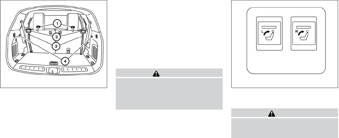
1. Folding 3rd row bench (P. 1-21)
2. Folding 2nd row bench (P. 1-20)
3. Roof-mounted curtain side-impact and
rollover supplemental air bag (P. 1-53)
4. Seat belts (P. 1-23)
5. Head restraints/headrests (P.1-8)
6. Supplemental front-impact air bags
(P.1-53)
7. Seats (1st row) (P. 1-2)
8. Occupant classification sensor
(weight sensor) (P.1-61)
9. Seat belt with pretensioner (P. 1-67)
10. Front seat-mounted side-impact
supplemental air bag (P. 1-53)
11. LATCH (Lower Anchors and Tethers for
CHildren) (P. 1-34)
12. 2nd row seat top tether strap anchor
(located on bottom of seatback)
(P. 1-48)
13. 3rd row bench seat top tether strap
anchor (located on bottom of seatback)
(P. 1-49)
See the page number indicated in paren-
theses for operating details.
LII2032
AIR BAGS, SEAT BELTS AND CHILD
RESTRAINTS
0-2 Illustrated table of contents
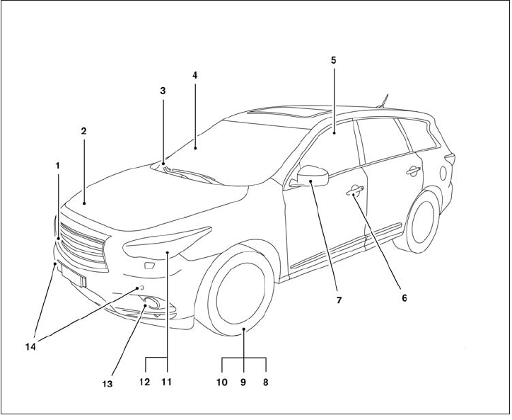
1. Front camera (if so equipped) (P. 4-29)
2. Engine hood (P. 3-20)
3. Windshield wiper and washer switch,
wiper blades (P. 2-26, 8-18)
4. Windshield-washer fluid (P. 8-18)
5. Power windows (P. 2-50)
6. Door locks, INFINITI Intelligent Key,
Remote Engine Start (if so equipped),
keys (P. 3-4, 3-7, 3-18,3-2)
7. Mirrors, side camera (if so equipped)
(P. 3-29, 4-29)
8. Tire pressure (P. 9-11)
9. Flat tire (P. 6-3)
10. Tire chains (P. 8-37)
11. Replacing bulbs (P. 8-25)
12. Headlight and turn signal switch
(P. 2-30)
13. Fog light switch (P. 2-34)
14. Corner sensors (if so equipped)
(P. 4-34)
See the page number indicated in paren-
theses for operating details.
LII2043
EXTERIOR FRONT
Illustrated table of contents 0-3
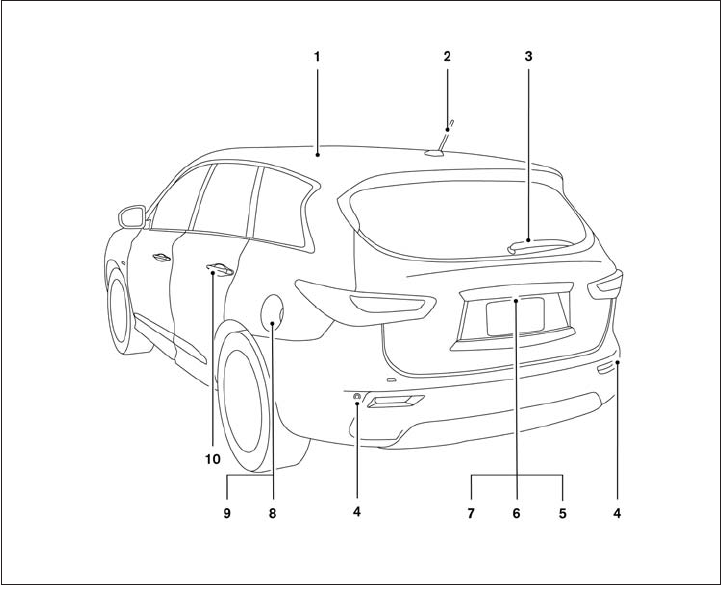
1. Moonroof, Panoramic sunshade
(if so equipped) (P. 2-52, 2-54)
2. Antenna (P.4-96)
3. Rear window wiper and washer switch
(P. 2-29)
4. Corner sensors (if so equipped)
(P. 4-34)
5. Liftgate release (P. 3-23)
6. Rear camera: Rearview monitor, AVM
rear camera (P.4-24, 4-29 )
7. Replacing bulbs (P. 8-25)
8. Fuel-filler cap, fuel recommendation
(P. 3-25, P. 9-3)
9. Fuel-filler door (P. 3-24)
10. Child safety rear door lock (P. 3-7)
See the page number indicated in paren-
theses for operating details.
LII2044
EXTERIOR REAR
0-4 Illustrated table of contents

1. Moonroof, Panoramic sunshade
(if so equipped) (P. 2-52, 2-54)
2. Storage (P. 2-43)
3. Map lights (P. 2-56)
4. Sun visors (P. 3-28)
5. Glove box, Console box (P. 2-46)
6. Seats (P. 1-2, 1-5, 1-7)
7. Cup holders (P. 2-45)
8. Luggage hooks (P. 2-48)
See the page number indicated in paren-
theses for operating details.
LII2033
PASSENGER COMPARTMENT
Illustrated table of contents 0-5

1. Vent (P. 4-46)
2. Headlight/fog light/turn signal switch
(P. 2-30)
3. Instrument brightness control (P. 2-34)
4. Meters, gauges, warning/indicator
lights and Vehicle Information Display
(P. 2-4, 2-7, 2-14)
5. Driver supplemental air bag/Horn
(P.1-53, P. 2-35)
6. Back-up Collision Intervention (BCI)
system switch (if so equipped) (P.5-32)
7. Twin trip odometer reset switch (P. 2-5)
8. Windshield wiper/washer switch and
rear window wiper/washer switch
(P. 2-26, P. 2-29)
9. Vent (P. 4-46)
10. Rear window and outside mirror
defroster switch (P. 2-30)
11. Center display (P. 4-11,
4-4)/Navigation system*
(if so equipped)
12. Automatic heater and air conditioning
controls (P. 4-47)
13. Vent (P. 4-46)
14. Front passenger supplemental air bag
(P. 1-53)
15. Vent (P. 4-46)
16. Glove box (P. 2-46)
17. Center multi-function control buttons
(P. 4-11, 4-4)
18. Power outlet (P.2-41)
19. Audio system controls (P. 4-54)
20. Shift lever (P.5-17)
21. Front passenger air bag status light
(P. 1-63)
22. Hazard warning flasher switch (P. 6-2)
LIC2290
INSTRUMENT PANEL
0-6 Illustrated table of contents
23. Ignition switch (P. 5-12)
24. Cruise control main/set switches
(if so equipped) and Intelligent cruise
control main/set switches
(if so equipped) (P. 5-51, P.5-53)
25. Dynamic Driver Assistance switch
(if so equipped) (P. 5-72)
26. Tilt steering wheel control (P. 3-27)
27. Bluetooth® Hands-Free Phone System
(P. 4-109, 4-123)
28. Steering wheel switch for audio control
(P.4-94)
29. Hood release (P. 3-20)
30. Vehicle Dynamic Control (VDC) OFF
switch (P. 2-40)
Heated steering wheel switch
(if so equipped) (P.2-39)
Headlight aiming control (P. 2-33)
Warning System switch
(if so equipped) (P. 2-40)
Power inverter switch (if so equipped)
(P. 2-41)
Liftgate release switch (P.3-20)
Power liftgate main switch (P. 3-23)
31. Control panel and Vehicle Information
Display switches (P.4-14, 2-15)
*: Refer to the separate Navigation System Own-
er’s Manual (if so equipped).
See the page number indicated in paren-
theses for operating details.
Illustrated table of contents 0-7
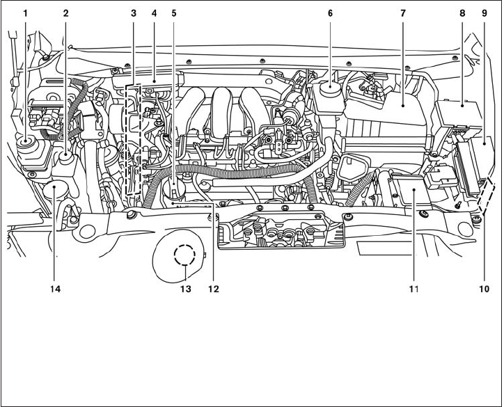
VQ35DE engine
1. Power steering fluid reservoir (P. 8-12)
2. Engine coolant reservoir (P. 8-7)
3. Drive belt location (P. 8-16)
4. Fuse box (P. 8-21 )
5. Engine oil filler cap (P. 8-10)
6. Brake fluid reservoir (P. 8-12)
7. Air cleaner (P. 8-18)
8. Fuse box (P. 8-21)
9. Fuse box/Fusible links (P. 8-21)
10. Fuse box (P. 8-21)
11. Battery (P. 8-14)
12. Engine oil dipstick (P. 8-10)
13. Radiator cap (P. 8-7)
14. Windshield-washer fluid reservoir
(P. 8-13)
See the page number indicated in paren-
theses for operating details.
LDI2266
ENGINE COMPARTMENT CHECK
LOCATIONS
0-8 Illustrated table of contents

Warning
light
Name Page
Anti-lock Braking
System (ABS) warn-
ing light
2-7
or
Brake warning light 2-8
Charge warning
light
2-8
Low tire pressure
warning light
2-8
Master warning light 2-10
Power steering
warning light
2-10
Seat belt warning
light and chime
2-11
Warning
light
Name Page
Supplemental air
bag warning light
2-11
Indicator
light
Name Page
Fog light indicator
light
2-11
Front passenger air
bag status light
2-11
High beam indicator
light (blue)
2-12
Intelligent Brake
Assist (IBA) off indi-
cator light (if so
equipped)
2-12
Malfunction indica-
tor light (MIL)
2-12
Security indicator
light
2-13
Indicator
light
Name Page
Side light and head-
light indicator light
(green)
2-13
Slip indicator light 2-13
Turn signal/hazard
indicator lights
2-13
Vehicle Dynamic
Control (VDC) off
indicator light
2-13
WARNING/INDICATOR LIGHTS
Illustrated table of contents 0-9
MEMO
0-10 Illustrated table of contents

1 Safety—Seats, seat belts and
supplemental restraint system
Seats . ...........................................1-2
Front power seat adjustment. . ...................1-3
2nd row bench seat adjustment ..................1-5
3rd row bench seat adjustment ..................1-7
1st row head restraints/headrests ................1-8
2nd row head restraints/headrests ..............1-12
3rd row head restraints/headrests ...............1-15
Flexible seating................................1-19
Seat belts .......................................1-23
Precautions on seat belt usage..................1-23
Pregnant women ..............................1-26
Injured persons................................1-26
Pre-crash seat belts with comfort function
(front seats) (if so equipped) . . ..................1-26
Three-point type seat belt with retractor ..........1-26
Seat belt extenders ............................1-30
Seat belt maintenance .........................1-30
Child safety ......................................1-31
Infants........................................1-31
Small children.................................1-32
Larger children ................................1-32
Child restraints ...................................1-32
Precautions on child restraints ..................1-32
LATCH (Lower Anchors and Tethers for
CHildren) System .............................1-34
Rear-facing child restraint installation using
LATCH.......................................1-38
Rear-facing child restraint installation using
the seat belts . . ...............................1-40
Forward-facing child restraint installation
using LATCH. . . ...............................1-42
Forward-facing child restraint installation
using the seat belts ............................1-44
Installing top tether strap
(2nd row bench seat) ..........................1-48
Installing top tether strap
(3rd row bench seat)...........................1-49
Booster seats .................................1-49
Supplemental restraint system .....................1-53
Precautions on supplemental restraint
system .......................................1-53
Supplemental air bag warning labels.............1-68
Supplemental air bag warning light ..............1-69

WARNING
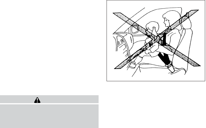
●Do not ride in a moving vehicle when
the seatback is reclined. This can be
dangerous. The shoulder belt will not
be against your body. In an accident,
you could be thrown into it and receive
neck or other serious injuries. You
could also slide under the lap belt and
receive serious internal injuries.
●For the most effective protection when
the vehicle is in motion, the seat should
be upright. Always sit well back in the
seat with both feet on the floor and
adjust the seat properly. See “Precau-
tions on seat belt usage” later in this
section.
●After adjustment, gently rock in the seat
to make sure it is securely locked.
●Do not leave children unattended inside
the vehicle. They could unknowingly ac-
tivate switches or controls. Unattended
children could become involved in seri-
ous accidents.
●The seatback should not be reclined
any more than needed for comfort. Seat
belts are most effective when the pas-
senger sits well back and straight up in
the seat. If the seatback is reclined, the
risk of sliding under the lap belt and
being injured is increased.
CAUTION
When adjusting the seat positions, be
sure not to contact any moving parts to
avoid possible injuries and/or damage.
ARS1152
SEATS
1-2 Safety—Seats, seat belts and supplemental restraint system

FRONT POWER SEAT ADJUSTMENT
Operating tips
●The power seat motor has an auto-reset
overload protection circuit. If the motor
stops during operation, wait 30 seconds,
then reactivate the switch.
●Do not operate the power seat switch for a
long period of time when the engine is off.
This will discharge the battery.
See “Automatic drive positioner” in “Pre-driving
checks and adjustments” for automatic drive po-
sitioner operation.
Forward and backward
Moving the switch forward or backward will slide
the seat forward or backward to the desired
position.
Reclining
Move the recline switch backward until the de-
sired angle is obtained. To bring the seatback
forward again, move the switch forward and
move your body forward. The seatback will move
forward.
The reclining feature allows adjustment of the
seatback for occupants of different sizes for
added comfort and to help obtain proper seat
belt fit. See “Precautions on seat belt usage” later
in this section. Also, the seatback can be reclined
to allow occupants to rest when the vehicle is
stopped and the shift lever is in P (Park).
LRS2130
Safety—Seats, seat belts and supplemental restraint system 1-3

Seat lifter
Push the switch up or push down to adjust the
angle and height of the seat cushion.
Lumbar support (driver’s seat)
The lumbar support feature provides adjustable
lower back support to the driver. Move the lever
up or down (manual) or move the switch forward
or backward (power) to adjust the seat lumbar
area.
LRS2131
Manual (if so equipped)
LRS2132
Power (if so equipped)
LRS2133
1-4 Safety—Seats, seat belts and supplemental restraint system

2ND ROW BENCH SEAT
ADJUSTMENT
Forward and backward
Pull the center of the bar 䊊
1up and hold it while
you slide the seat forward or backward to the
desired position. Release the bar to lock the seat
in position.
Reclining
To recline the seatback, pull up on the lever 䊊
2
and lean back. To bring the seatback forward, pull
the lever 䊊
2up and lean your body forward.
Release the lever to lock the seatback in position.
The recline feature allows adjustment of the seat-
back for occupants of different sizes for added
comfort and to help obtain proper seat belt fit
(see “Precautions on seat belt usage” later in this
section). Also, the seatback can be reclined to
allow occupants to rest when the vehicle is
stopped and the shift lever is in P (Park).
WARNING
●After adjustment, gently rock in the seat
to make sure it is securely locked.
●Do not ride in a moving vehicle when
the seatback is reclined. This can be
dangerous. The shoulder belt will not
be against your body. In an accident,
you could be thrown into it and receive
neck or other serious injuries. You
could also slide under the lap belt and
receive serious internal injuries.
●For the most effective protection when
the vehicle is in motion, the seat should
be upright. Always sit well back in the
seat and adjust the seat belt properly.
See “Precautions on seat belt usage”
later in this section.
One touch walk-in function
The 3rd row can be accessed from outside the
vehicle by using the seatback release lever lo-
cated on the 2nd row seatback. If a child safety
seat is installed on the passenger’s side of the
2nd row seat, the 3rd row can be accessed
without removing the child safety seat.
Multi-mode
WARNING
When returning the seat to its original
position, confirm that the seat and seat-
back are locked properly.
Outboard seats
LRS2143 LRS2142
Safety—Seats, seat belts and supplemental restraint system 1-5

CAUTION
●Be careful not to pinch your hand or foot
or bump your head when operating the
walk-in seat.
●Do not drive with the 2nd row seat
tipped up.
●Be careful not to allow the 2nd row seat
to pinch, hit any part of your body or
other people when operating the 2nd
row seat. Make sure the seat path is
clear of all objects before moving the
seat.
To enter the 3rd row from outside the vehicle, lift
up on the seatback lever located on the upper
outboard side of the seatback on the 2nd row
bench seat. This will release the back of the seat
and fold up the seat cushion. This will also re-
lease the seat tracks so you will be able to slide
the seat forward or backward.
Slide the entire seat forward for access to the
rear seat.
To return the seat to a locked position, push the
upper seatback rearward until the seatback and
tracks are locked. Push the seat cushion down.
Child seat access mode
The passenger’s side of the 2nd row seat can be
slid forward for easy entry or exit from the 3rd row
bench seat without a child safety seat being
removed.
To enter the 3rd row from outside the vehicle, lift
up on the seatback lever located on the upper
outboard side of the seatback on the 2nd row
bench seat. This will release the seatback, tilt the
seat, and then release the tracks so you will be
able to slide the seat forward or backward.
Slide the entire seat forward for access to the
rear seat.
To return the seat to a locked position, push the
upper seatback rearward until the seatback and
track are locked.
WARNING
●Do not leave a child in the child safety
seat when operating the Child seat ac-
cess mode.
●When returning the seat to its original
position, confirm that the seat and seat-
back are locked properly.
CAUTION
●Be careful not to pinch your hand or foot
or bump your head when operating the
walk-in seat.
●Do not drive with the 2nd row seat
tipped up.
●Be careful not to allow the 2nd row seat
to pinch, hit any part of your body or
other people when operating the 2nd
row seat. Make sure the seat path is
clear of all objects before moving the
seat.
Exiting the 3rd row
To exit the 3rd row from either seating position, lift
the upper seatback release lever to the upper-
most position. This will release the back of the
seat, fold the seat cushion up and release the
tracks.
Slide the entire seat forward.
To return the seat to a locked position push the
upper seatback rearward until the seatback and
track are locked.
1-6 Safety—Seats, seat belts and supplemental restraint system

WARNING
When returning the seat to its original
position, confirm that the seat and seat-
back are locked properly.
Be careful not to pinch your hand or foot
or bump your head when operating the
walk-in seat.
3RD ROW BENCH SEAT
ADJUSTMENT
Reclining
To recline the seatback, pull up on the latch
located on the outside corner of each seatback.
Lean back until the desired angle is obtained.
To bring the seatback forward again, pull up on
the latch and pull the seatback upright until the
desired angle is obtained.
The recline feature allows adjustment of the seat-
back for occupants of different sizes for added
comfort and to help obtain proper seat belt fit.
See “Precautions on seat belt usage” later in this
section. Also, the seatback can be reclined to
allow occupants to rest when the vehicle is
stopped and the shift lever is in P (Park).
WARNING
●After adjustment, gently rock in the seat
to make sure it is securely locked.
●Do not ride in a moving vehicle when
the seatback is reclined. This can be
dangerous. The shoulder belt will not
be against your body. In an accident,
you could be thrown into it and receive
neck or other serious injuries. You
could also slide under the lap belt and
receive serious internal injuries.
●For the most effective protection when
the vehicle is in motion, the seat should
be upright. Always sit well back in the
seat and adjust the seat belt properly.
See “Precautions on seat belt usage”
later in this section.
Outboard seats
LRS2147
Safety—Seats, seat belts and supplemental restraint system 1-7

1ST ROW HEAD RESTRAINTS/
HEADRESTS
WARNING
●Head restraints/headrests supplement
the other vehicle safety systems. They
may provide additional protection
against injury in certain rear end colli-
sions. Adjust the head
restraints/headrests properly, as speci-
fied in this section. Check the adjust-
ment after someone else uses the seat.
Do not attach anything to the head
restraint/headrest stalks. Do not use
the seat if the head restraint/headrest
has been removed. If the head
restraint/headrest was removed, rein-
stall and properly adjust the head
restraint/headrest before an occupant
uses the seating position. Failure to fol-
low these instructions can reduce the
effectiveness of the head
restraints/headrests. This may increase
the risk of serious injury or death in a
collision.
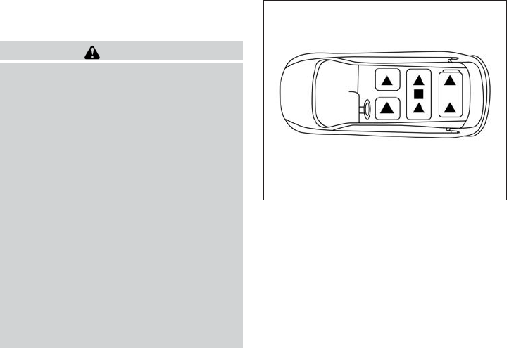
The illustration shows the seating positions
equipped with head restraints/headrests. The
first row head restraints are adjustable.
䉱Indicates the seating position is equipped with
a head restraint.
䡲Indicates the seating position is equipped with
a headrest.
+ Indicates the seating position is not equipped
with a head restraint or headrest.
●Your vehicle is equipped with a head
restraint/headrest that may be integrated,
adjustable or non-adjustable.
●Adjustable head restraints/headrests have
multiple notches along the post to lock them
in a desired adjustment position.
●The non-adjustable head
restraints/headrests have single locking
notches to secure them to the seat frame.
●Proper Adjustment:
– For the adjustable type, align the head
restraint/headrest so the center of your
ear is approximately level with the center
of the head restraint/headrest.
– If your ear position is still higher than the
recommended alignment, place the head
restraint/headrest at the highest position.
●If the head restraint/headrest has been re-
moved, ensure that it is reinstalled and
locked in place before riding in that desig-
nated seating position.
LRS2308
1-8 Safety—Seats, seat belts and supplemental restraint system

Adjustable head restraint/headrest
components
1. Removable head restraint/headrest
2. Multiple notches
3. Lock knob
4. Stalks
Non-adjustable head restraint/
headrest components
1. Removable head restraint/headrest
2. Single Notch
3. Lock knob
4. Stalks
Removable (without Dual head
restraint/headrest DVD system only)
CAUTION
Do not remove head restraint/headrest
from vehicles equipped with Dual head
restraint/headrest DVD system. Removal
may damage the system wiring.
LRS2300 LRS2299 LRS2302
Safety—Seats, seat belts and supplemental restraint system 1-9

Use the following procedure to remove the head
restraints/headrests
1. Pull the head restraint/headrest up to the
highest position.
2. Push and hold the lock knob.
3. Remove the head restraint/headrest from
the seat.
4. Store the head restraint/headrest properly in
a secure place so it is not loose in the
vehicle.
5. Reinstall and properly adjust the head
restraint/headrest before an occupant uses
the seating position. Install
1. Align the head restraint/headrest stalks with
the holes in the seat. Make sure the head
restraint/headrest is facing the correct di-
rection. The stalk with the notch (notches)
䊊
1must be installed in the hole with the lock
knob 䊊
2.
2. Push and hold the lock knob and the head
restraint/headrest down.
3. Properly adjust the head restraint/headrest
before an occupant uses the seating posi-
tion.
For adjustable head restraint/headrest
Adjust the head restraint/headrest so the center
is level with the center of your ears. If your ear
position is still higher than the recommended
alignment, place the head restraint/headrest at
the highest position.
LRS2303 WRS0134
1-10 Safety—Seats, seat belts and supplemental restraint system

For non-adjustable head restraint/
headrest
Make sure the head restraint/headrest is posi-
tioned so the lock knob is engaged in the notch
before riding in that designated seating position.
To raise the head restraint/headrest,
pull it up
Make sure the head restraint/headrest is posi-
tioned so the lock knob is engaged in the notch
before riding in that designated seating position.
To lower, push and hold the lock knob
and push the head restraint/headrest
down.
Make sure the head restraint/headrest is posi-
tioned so the lock knob is engaged in the notch
before riding in that designated seating position.
LRS2304 LRS2305 LRS2306
Safety—Seats, seat belts and supplemental restraint system 1-11
2ND ROW HEAD RESTRAINTS/
HEADRESTS
WARNING
●Head restraints/headrests supplement
the other vehicle safety systems. They
may provide additional protection
against injury in certain rear end colli-
sions. Adjust the head
restraints/headrests properly, as speci-
fied in this section. Check the adjust-
ment after someone else uses the seat.
Do not attach anything to the head
restraint/headrest stalks. Do not use
the seat if the head restraint/headrest
has been removed. If the head
restraint/headrest was removed, rein-
stall and properly adjust the head
restraint/headrest before an occupant
uses the seating position. Failure to fol-
low these instructions can reduce the
effectiveness of the head
restraints/headrests. This may increase
the risk of serious injury or death in a
collision.
The illustration shows the seating positions
equipped with head restraints/headrests. The
second row head restraints are removable and
adjustable.
䉱Indicates the seating position is equipped with
a head restraint.
䡲Indicates the seating position is equipped with
a headrest.
+ Indicates the seating position is not equipped
with a head restraint or headrest.
●Your vehicle is equipped with a head
restraint/headrest that may be integrated,
adjustable or non-adjustable.
●Adjustable head restraints/headrests have
multiple notches along the stalk to lock them
in a desired adjustment position.
●The non-adjustable head
restraints/headrests have single locking
notches to secure them to the seat frame.
●Proper Adjustment:
– For the adjustable type, align the head
restraint/headrest so the center of your
ear is approximately level with the center
of the head restraint/headrest.
– If your ear position is still higher than the
recommended alignment, place the head
restraint/headrest at the highest position.
●If the head restraint/headrest has been re-
moved, ensure that it is reinstalled and
locked in place before riding in that desig-
nated seating position
LRS2308
1-12 Safety—Seats, seat belts and supplemental restraint system

Adjustable head restraint/headrest
components
1. Removable head restraint/headrest
2. Multiple notches
3. Lock knob
4. Stalks
Non-adjustable head restraint/
headrest components
1. Removable head restraint/headrest
2. Single Notch
3. Lock knob
4. Stalks
Removable
Use the following procedure to remove the head
restraints/headrests
1. Pull the head restraint/headrest up to the
highest position.
2. Push and hold the lock knob.
3. Remove the head restraint/headrest from
the seat.
4.
Store the head restraint/headrest properly in a
secure place so it is not loose in the vehicle.
5. Reinstall and properly adjust the head
restraint/headrest before an occupant uses
the seating position.
LRS2300 LRS2299 LRS2302
Safety—Seats, seat belts and supplemental restraint system 1-13

Install
1. Align the head restraint/headrest stalks with
the holes in the seat. Make sure the head
restraint/headrest is facing the correct di-
rection. The stalk with the notch (notches)
䊊
1must be installed in the hole with the lock
knob 䊊
2.
2. Push and hold the lock knob and the head
restraint/headrest down.
3. Properly adjust the head restraint/headrest
before an occupant uses the seating posi-
tion.
For adjustable head restraint/headrest
Adjust the head restraint/headrest so the center
is level with the center of your ears. If your ear
position is still higher than the recommended
alignment, place the head restraint/headrest at
the highest position.
For non-adjustable head restraint/
headrest
Make sure the head restraint/headrest is posi-
tioned so the lock knob is engaged in the notch
before riding in that designated seating position.
LRS2303 WRS0134 LRS2304
1-14 Safety—Seats, seat belts and supplemental restraint system

To raise the head restraint/headrest,
pull it up
Make sure the head restraint/headrest is posi-
tioned so the lock knob is engaged in the notch
before riding in that designated seating position.
To lower, push and hold the lock knob
and push the head restraint/headrest
down.
Make sure the head restraint/headrest is posi-
tioned so the lock knob is engaged in the notch
before riding in that designated seating position.
3RD ROW HEAD RESTRAINTS/
HEADRESTS
WARNING
●Head restraints/headrests supplement
the other vehicle safety systems. They
may provide additional protection
against injury in certain rear end colli-
sions. Adjust the head
restraints/headrests properly, as speci-
fied in this section. Check the adjust-
ment after someone else uses the seat.
Do not attach anything to the head
restraint/headrest stalks. Do not use
the seat if the head restraint/headrest
has been removed. If the head
restraint/headrest was removed, rein-
stall and properly adjust the head
restraint/headrest before an occupant
uses the seating position. Failure to fol-
low these instructions can reduce the
effectiveness of the head
restraints/headrests. This may increase
the risk of serious injury or death in a
collision.
LRS2305 LRS2306
Safety—Seats, seat belts and supplemental restraint system 1-15

The illustration shows the seating positions
equipped with head restraints/headrests. The
third row head restraints are removable but not
adjustable.
䉱Indicates the seating position is equipped with
a head restraint.
䡲Indicates the seating position is equipped with
a headrest.
+ Indicates the seating position is not equipped
with a head restraint or headrest.
●Your vehicle is equipped with a head
restraint/headrest that may be integrated,
adjustable or non-adjustable.
●Adjustable head restraints/headrests have
multiple notches along the post to lock them
in a desired adjustment position.
●The non-adjustable head
restraints/headrests have single locking
notches to secure them to the seat frame.
●Proper Adjustment:
– For the adjustable type, align the head
restraint/headrest so the center of your
ear is approximately level with the center
of the head restraint/headrest.
– If your ear position is still higher than the
recommended alignment, place the head
restraint/headrest at the highest position.
●If the head restraint/headrest has been re-
moved, ensure that it is reinstalled and
locked in place before riding in that desig-
nated seating position.
Adjustable head restraint/headrest
components
1. Removable head restraint/headrest
2. Multiple notches
3. Lock knobs
4. Stalks
LRS2308 LRS2310
1-16 Safety—Seats, seat belts and supplemental restraint system

Non-adjustable head restraint/
headrest components
1. Removable head restraint/headrest
2. Single Notch
3. Lock knobs
4. Stalks
Removable
Use the following procedure to remove the head
restraints/headrests
1. Pull the head restraint/headrest up to the
highest position.
2. Push and hold the lock knobs.
3. Remove the head restraint/headrest from
the seat.
4.
Store the head restraint/headrest properly in a
secure place so it is not loose in the vehicle.
5. Reinstall and properly adjust the head
restraint/headrest before an occupant uses
the seating position.
Install
1. Align the head restraint/headrest stalks with
the holes in the seat. Make sure the head
restraint/headrest is facing the correct di-
rection. The stalk with the notch (notches)
䊊
1must be installed in the hole with the lock
knobs 䊊
2.
2. Push and hold the lock knobs and the head
restraint/headrest down.
3. Properly adjust the head restraint/headrest
before an occupant uses the seating posi-
tion.
LRS2315 LRS2311 LRS2312
Safety—Seats, seat belts and supplemental restraint system 1-17

For adjustable head restraint/headrest
Adjust the head restraint/headrest so the center
is level with the center of your ears. If your ear
position is still higher than the recommended
alignment, place the head restraint/headrest at
the highest position.
For non-adjustable head restraint/
headrest
Make sure the head restraint/headrest is posi-
tioned so the lock knob is engaged in the notch
before riding in that designated seating position.
To raise the head restraint/headrest,
pull it up
Make sure the head restraint/headrest is posi-
tioned so the lock knob is engaged in the notch
before riding in that designated seating position.
WRS0134 LRS2304 LRS2305
1-18 Safety—Seats, seat belts and supplemental restraint system

To lower, push and hold the lock knob
and push the head restraint/headrest
down.
Make sure the head restraint/headrest is posi-
tioned so the lock knob is engaged in the notch
before riding in that designated seating position.
Folding head restraints/headrests
To fold the head restraint/headrest, pull the strap
located on the rear of the head
restraint/headrest.
If the head restraint/headrest has been folded,
make sure that it is returned to the upright posi-
tion.
Make sure the head restraint/headrest is posi-
tioned so the lock knobs are engaged in the
notch before riding in that designated seating
position.
WARNING
When the seat is returned to the normal
seating position, the head
restraints/headrests must be returned to
the upright position to properly protect
vehicle occupants.
FLEXIBLE SEATING
WARNING
●Never allow anyone to ride in the cargo
area or on the rear seats when they are
in the fold-down position. In a collision,
people riding in these areas without
proper restraints are more likely to be
seriously injured or killed.
●Do not allow people to ride in any area
of your vehicle that is not equipped with
seats and seat belts. Be sure everyone
in your vehicle is in a seat and using a
seat belt properly.
●Do not fold down the rear seats when
occupants are in the rear seat area or
any luggage is on the rear seats.
LRS2306 LRS2307
Safety—Seats, seat belts and supplemental restraint system 1-19

●Head restraints/headrests should be
adjusted properly as they may provide
significant protection against injury in
an accident. Always replace and adjust
them properly if they have been re-
moved for any reason.
●If the head restraints/headrests are re-
moved for any reason, they should be
securely stored to prevent them from
causing injury to passengers or damage
to the vehicle in case of sudden braking
or an accident
●When returning the seatbacks to the
upright position, be certain they are
completely secured in the latched posi-
tion. If they are not completely secured,
passengers may be injured in an acci-
dent or sudden stop.
●Properly secure all cargo to help pre-
vent it from sliding or shifting. Do not
place cargo higher than the seatbacks.
In a sudden stop or collision, unsecured
cargo could cause personal injury.
Folding the 2nd row bench seat
To fold the 2nd row bench seat flat for maximum
cargo hauling:
1. Make sure that the head
restraints/headrests are lowered. For maxi-
mum cargo hauling, remove the center head
restraints/headrests. To remove the head
restraints/headrests, push and hold the lock
knob while moving the head
restraints/headrests in an upward direction.
Store the head restraints/headrests properly
so it is not loose in the vehicle.
2. Stow the 2nd row seat belts in the seat belt
hooks found on the sides of the vehicle.
3. Lift up on the recline lever on the side of the
outboard seats to fold the seatbacks flat.
4. To return the 2nd row bench seats to a
seating position, push up on the seatback
until it latches in place.
LRS2144
1-20 Safety—Seats, seat belts and supplemental restraint system
Folding the 3rd row seats
To fold the 3rd row seats flat for maximum cargo
capacity:
1. Pull the strap 䊊
1to release the head
restraint/headrest forward.
2. Stow the 3rd row seat belts in the seat belt
hooks 䊊
4found on the sides of the cargo
area.
3. Pull up on the latch 䊊
2located in the upper
corner of each seatback and lower the seat-
back forward over the seat base.
To return the 3rd row seats to a seating position:
1. Use the pull straps 䊊
3to raise each seat-
back. Pull back until the seatback latches
into position. Make sure to properly raise
each seatback to an upright and se-
cured position.
2. Do not use the pull strap to return the head
restraint/headrest to the upright position.
Pull back on the head restraint/headrest until
it latches in the upright position.
WARNING
When the seat is returned to the normal
seating position, the head
restraints/headrests must be returned to
the upright position to properly protect
vehicle occupants.
3rd row power folding seats (if so
equipped)
WARNING
Make sure the seat(s) is returned to the
full upright position before a passenger
sits in the seat(s).
LRS2145 LRS2325
Safety—Seats, seat belts and supplemental restraint system 1-21

CAUTION
When folding or returning the seat(s) to
the upright position, to avoid injury to
yourself and others:
●Make sure that the seat path is clear
before moving the seat.
●Be careful not to allow hands or feet to
get caught or pinched in the seat.
Before operating the 3rd row seats:
●Make sure the 2nd row seatback isn’t re-
clined.
●Pull the strap to release the head
restraints/headrests forward.
●Stow the 3rd row seat belts in the seat belt
hooks found on the sides of the cargo area.
●Make sure that there are no objects on the
seatback cushion.
3rd row seats are manual fold only. For additional
information, see “Folding the 3rd row seats” in
this section.
Push and hold the top portion of the switch. The
seatback will be returned automatically. The seat-
back will rise up while holding the switch.
A chime will sound once to indicate the start of
the operation.
One long continuous warning chime will sound if
the seat isn’t in the full upright or folded position
when the ignition switch is placed in the ON
position. If the warning beep is still present after
one complete cycle and if the seats are in the full
upright or folded position, see your INFINITI re-
tailer.
If the ignition switch is off, the power folding
seats are always operational.
If the ignition switch is on, the power folding seats
are only operational when the shift lever is in P
(Park) or N (Neutral).
If the engine is started during operation, the
seat(s) will temporarily pause.
NOTE:
Operating the power folding seats can dis-
charge the vehicle battery if the vehicle is
not running.
WARNING
●When the seat is returned to the normal
seating position, the head
restraints/headrests must be returned
to the upright position to properly pro-
tect vehicle occupants.
●Never allow anyone to ride in the cargo
area or on the rear seat when it is in the
fold-down position. Use of these areas
by passengers without proper restraints
could result in serious injury in an acci-
dent or sudden stop.
●When returning the seatbacks to the
upright position, be certain they are
completely secured in the latched posi-
tion. If they are not completely secured,
passengers may be injured in an acci-
dent or sudden stop.
●Properly secure all cargo to help pre-
vent it from sliding or shifting. Do not
place cargo higher than the seatbacks.
In a sudden stop or collision, unsecured
cargo could cause personal injury.
CAUTION
When operating the rear power seatback
return, make sure that the vehicle is
stopped and the shift lever is in the P
(Park) position.
1-22 Safety—Seats, seat belts and supplemental restraint system

PRECAUTIONS ON SEAT BELT
USAGE
If you are wearing your seat belt properly ad-
justed and you are sitting upright and well back in
your seat with both feet on the floor, your chances
of being injured or killed in an accident and/or the
severity of injury may be greatly reduced. INFINITI
strongly encourages you and all of your passen-
gers to buckle up every time you drive, even if
your seating position includes a supplemental air
bag.
Most U.S. states and Canadian provinces or
territories specify that seat belts be worn at
all times when a vehicle is being driven.
SSS0136
SEAT BELTS
Safety—Seats, seat belts and supplemental restraint system 1-23

WARNING
●Every person who drives or rides in this
vehicle should use a seat belt at all
times. Children should be properly re-
strained in the rear seat and, if appro-
priate, in a child restraint.
WARNING
●The seat belt should be properly ad-
justed to a snug fit. Failure to do so may
reduce the effectiveness of the entire
restraint system and increase the
chance or severity of injury in an acci-
dent. Serious injury or death can occur if
the seat belt is not worn properly.
SSS0134 SSS0016
1-24 Safety—Seats, seat belts and supplemental restraint system

WARNING
●Always route the shoulder belt over
your shoulder and across your chest.
Never put the belt behind your back,
under your arm or across your neck. The
belt should be away from your face and
neck, but not falling off your shoulder.
●Position the lap belt as low and snug as
possible AROUND THE HIPS, NOT THE
WAIST. A lap belt worn too high could
increase the risk of internal injuries in
an accident.
●Be sure the seat belt tongue is securely
fastened to the proper buckle.
●Do not wear the seat belt inside out or
twisted. Doing so may reduce its
effectiveness.
●Do not allow more than one person to
use the same seat belt.
●Never carry more people in the vehicle
than there are seat belts.
●If the seat belt warning light glows con-
tinuously while the ignition is turned
ON with all doors closed and all seat
belts fastened, it may indicate a mal-
function in the system. Have the system
checked by a INFINITI retailer.
●No changes should be made to the seat
belt system. For example, do not modify
the seat belt, add material, or install
devices that may change the seat belt
routing or tension. Doing so may affect
the operation of the seat belt system.
Modifying or tampering with the seat
belt system may result in serious per-
sonal injury.
●Once a seat belt pretensioner has acti-
vated, it cannot be reused and must be
replaced together with the retractor.
See your INFINITI retailer.
●Removal and installation of preten-
sioner system components should be
done by a INFINITI retailer.
●All seat belt assemblies, including re-
tractors and attaching hardware, should
be inspected after any collision by a
INFINITI retailer. INFINITI recommends
that all seat belt assemblies in use dur-
ing a collision be replaced unless the
collision was minor and the belts show
no damage and continue to operate
properly. Seat belt assemblies not in
use during a collision should also be
inspected and replaced if either dam-
age or improper operation is noted.
●All child restraints and attaching hard-
ware should be inspected after any col-
lision. Always follow the restraint
manufacturer’s inspection instructions
and replacement recommendations.
The child restraints should be replaced
if they are damaged.
SSS0014
Safety—Seats, seat belts and supplemental restraint system 1-25

PREGNANT WOMEN
INFINITI recommends that pregnant women use
seat belts. The seat belt should be worn snug,
and always position the lap belt as low as pos-
sible around the hips, not the waist. Place the
shoulder belt over your shoulder and across your
chest. Never run the lap/shoulder belt over your
abdominal area. Contact your doctor for specific
recommendations.
INJURED PERSONS
INFINITI recommends that injured persons use
seat belts. Check with your doctor for specific
recommendations.
PRE-CRASH SEAT BELTS WITH
COMFORT FUNCTION (front seats)
(if so equipped)
The pre-crash seat belt tightens the seat belt with
a motor to help restrain front seat occupants. This
helps reduce the risk of injury in a collision.
The motor retracts the seat belt under the follow-
ing emergency conditions:
●During emergency braking.
●During sudden steering maneuvers
●Activation of the Intelligent Brake Assist
(IBA) system. See “Intelligent Brake Assist
(IBA) system” in Starting and driving” sec-
tion.).
●In the event of certain types of rollover colli-
sions.
The pre-crash seat belt will not be active when:
●the seat belt is not fastened.
●the vehicle speed is under 10 mph (15 km/h)
during emergency braking.
●the vehicle speed is under 19 mph (30 km/h)
during sudden steering maneuvers or cer-
tain types of rollover collisions.
The pre-crash seat belt will not be active when
the brake pedal is not depressed except when
sudden steering maneuvers occur and the Intel-
ligent Brake Assist (IBA) system activates.
The motor also retracts the seat belt when the
seat belt is fastened or unfastened. When the
seat belt is fastened, the motor tightens the seat
belt for a snug fit. When the seat belt is unfas-
tened, the motor retracts the seat belt. If the seat
belt is not fully retracted, the motor retracts the
seat belt when the door is opened.
Always wear your seat belt correctly and sit up-
right and well back.
If the motor cannot retract the seat belt when the
seat belt is fastened or unfastened, it may indi-
cate the pre-crash seat belt system has a mal-
function. Have your INFINITI retailer check and
repair the system.
When the seat belt is retracted repeatedly in a
short period of time, the motor may not be able to
retract the seat belt. After 8 minutes, the motor
reactivates and retracts the seat belt. If the seat
belt still cannot be retracted by the motor, the
pre-crash seat belt system has a malfunction.
Have your INFINITI retailer check and repair the
system.
THREE-POINT TYPE SEAT BELT
WITH RETRACTOR
WARNING
●Every person who drives or rides in this
vehicle should use a seat belt at all
times.
●Do not ride in a moving vehicle when
the seatback is reclined. This can be
dangerous. The shoulder belt will not
be against your body. In an accident,
you could be thrown into it and receive
neck or other serious injuries. You
could also slide under the lap belt and
receive serious internal injuries.
1-26 Safety—Seats, seat belts and supplemental restraint system

●For the most effective protection when
the vehicle is in motion, the seat should
be upright. Always sit well back in the
seat with both feet on the floor and
adjust the seat belt properly.
●Do not allow children to play with the
seat belts. Most seating positions are
equipped with Automatic Locking Re-
tractor (ALR) mode seat belts. If the seat
belt becomes wrapped around a child’s
neck with the ALR mode activated, the
child can be seriously injured or killed if
the seat belt retracts and becomes
tight. This can occur even if the vehicle
is parked. Unbuckle the seat belt to
release the child. If the seat belt cannot
be unbuckled or is already unbuckled,
release the child by cutting the seat belt
with a suitable tool (such as a knife or
scissors) to release the seat belt.
Fastening the seat belts
1. Adjust the seat. See “Seats” earlier in this
section.
䊊
2Slowly pull the seat belt out of the retractor
and insert the tongue into the buckle until
you hear and feel the latch engage.
●The retractor is designed to lock dur-
ing a sudden stop or on impact. A
slow pulling motion permits the seat
belt to move and allows you some
freedom of movement in the seat.
●If the seat belt cannot be pulled from
its fully retracted position, firmly pull
the belt and release it. Then
smoothly pull the belt out of the re-
tractor.
Front seat shown
LRS2148 WRS0137
Safety—Seats, seat belts and supplemental restraint system 1-27

䊊
3Position the lap belt portion low and snug
on the hips as shown.
䊊
4Pull the shoulder belt portion toward the
retractor to take up extra slack. Be sure the
shoulder belt is routed over your shoulder
and across your chest.
The front passenger seat and the rear seating
positions three-point seat belts have two modes
of operation:
●Emergency Locking Retractor (ELR)
●Automatic Locking Retractor (ALR)
The Emergency Locking Retractor (ELR) mode
allows the seat belt to extend and retract to allow
the driver and passengers some freedom of
movement in the seat. The ELR locks the seat belt
when the vehicle slows down rapidly or during
certain impacts.
The Automatic Locking Retractor (ALR) mode
(child restraint mode) locks the seat belt for child
restraint installation.
When the ALR mode is activated, the seat belt
cannot be extended again until the seat belt
tongue is detached from the buckle and fully
retracted. The seat belt returns to the ELR mode
after the seat belt fully retracts. See “Child re-
straints” later in this section for more information.
The ALR mode should be used only for
child restraint installation. During normal
seat belt use by an occupant, the ALR mode
should not be activated. If it is activated, it
may cause uncomfortable seat belt ten-
sion.
WARNING
When fastening the seat belts, be certain
that the seatbacks are completely secured
in the latched position. If they are not
completely secured, passengers may be
injured in an accident or sudden stop.
Unfastening the seat belts
䊊
1To unfasten the seat belt, press the button on
the buckle. The seat belt automatically re-
tracts.
Checking seat belt operation
Seat belt retractors are designed to lock seat belt
movement by two separate methods:
●When the seat belt is pulled quickly from the
retractor.
●When the vehicle slows down rapidly.
WRS0138 WRS0139
1-28 Safety—Seats, seat belts and supplemental restraint system

To increase your confidence in the seat belts,
check the operation as follows.
●Grasp the shoulder belt and pull forward
quickly. The retractor should lock and re-
strict further belt movement.
If the retractor does not lock during this check or
if you have any questions about seat belt opera-
tion, see an INFINITI retailer .
Shoulder belt height adjustment (front
and 2nd row outboard seats)
The shoulder belt anchor height should be ad-
justed to the position best for you. (See “Precau-
tions on seat belt usage”).
To adjust, push the button 䊊
A, and then move the
shoulder belt anchor to the desired position, so
that the belt passes over the center of the shoul-
der. The belt should be away from your face and
neck, but not falling off of your shoulder. Release
the adjustment button to lock the shoulder belt
anchor into position.
WARNING
●After adjustment, release the adjust-
ment button and try to move the shoul-
der belt anchor up and down to make
sure it is securely fixed in position.
●The shoulder belt anchor height should
be adjusted to the position best for you.
Failure to do so may reduce the effec-
tiveness of the entire restraint system
and increase the chance or severity of
injury in an accident.
●The shoulder belt should rest on the
middle of the shoulder. It must not rest
against the neck.
●Be sure that the seat belt is not twisted
in any way.
●Be sure that the shoulder belt anchor is
secured by trying to move the shoulder
belt anchor up and down after
adjustment.
SSS0896
Safety—Seats, seat belts and supplemental restraint system 1-29

Seat belt hook
When the seat belt is not in use and when folding
down the rear seats, hook the rear seat belts on
the seat belt hooks.
SEAT BELT EXTENDERS
If, because of body size or driving position, it is
not possible to properly fit the lap/shoulder belt
and fasten it, an extender that is compatible with
the installed seat belts is available that can be
purchased. The extender adds approximately 8 in
(200 mm) of length and may be used for either
the driver or front passenger seating position.
Seat belt extenders are available for the:
●Driver and front passenger seating position
●2nd and 3rd row seating position
See a INFINITI retailer for assistance with pur-
chasing an extender if an extender is required.
WARNING
●Only INFINITI seat belt extenders, made
by the same company which made the
original equipment seat belts, should
be used with INFINITI seat belts.
●Adults and children who can use the
standard seat belt should not use an
extender. Such unnecessary use could
result in serious personal injury in the
event of an accident.
●Never use seat belt extenders to install
child restraints. If the child restraint is
not secured properly, the child could be
seriously injured in a collision or a sud-
den stop.
SEAT BELT MAINTENANCE
●To clean the seat belt webbing, apply a
mild soap solution or any solution recom-
mended for cleaning upholstery or carpet.
Then wipe with a cloth and allow the seat
belts to dry in the shade. Do not allow the
seat belts to retract until they are completely
dry.
●If dirt builds up in the shoulder belt
guide of the seat belt anchors, the seat
belts may retract slowly. Wipe the shoulder
belt guide with a clean, dry cloth.
●Periodically check to see that the seat
belt and the metal components such as
buckles, tongues, retractors, flexible wires
and anchors, work properly. If loose parts,
deterioration, cuts or other damage on the
webbing is found, the entire seat belt as-
sembly should be replaced.
3rd row shown; 2nd row similar
LRS2157
1-30 Safety—Seats, seat belts and supplemental restraint system

WARNING
Do not allow children to play with the seat
belts. Most seating positions are
equipped with Automatic Locking Retrac-
tor (ALR) mode seat belts. If the seat belt
becomes wrapped around a child’s neck
with the ALR mode activated, the child can
be seriously injured or killed if the seat
belt retracts and becomes tight. This can
occur even if the vehicle is parked. Un-
buckle the seat belt to release the child. If
the seat belt cannot be unbuckled or is
already unbuckled, release the child by
cutting the seat belt with a suitable tool
(such as a knife or scissors) to release the
seat belt.
Children need adults to help protect them.
They need to be properly restrained.
In addition to the general information in this
manual, child safety information is available from
many other sources, including doctors, teachers,
government traffic safety offices, and community
organizations. Every child is different, so be sure
to learn the best way to transport your child.
There are three basic types of child restraint
systems:
●Rear-facing child restraint
●Forward-facing child restraint
●Booster seat
The proper restraint depends on the child’s size.
Generally, infants up to about 1 year and less
than 20 lbs (9 kg) should be placed in rear-facing
child restraints. Forward-facing child restraints
are available for children who outgrow rear-
facing child restraints and are at least 1 year old.
Booster seats are used to help position a vehicle
lap/shoulder belt on a child who can no longer
use a forward-facing child restraint.
WARNING
Infants and children need special protec-
tion. The vehicle’s seat belts may not fit
them properly. The shoulder belt may
come too close to the face or neck. The lap
belt may not fit over their small hip bones.
In an accident, an improperly fitting seat
belt could cause serious or fatal injury.
Always use appropriate child restraints.
All U.S. states and Canadian provinces or territo-
ries require the use of approved child restraints
for infants and small children. See “Child re-
straints” later in this section.
A child restraint may be secured in the vehicle by
using either the LATCH (Lower Anchor and Teth-
ers for CHildren) system or with the vehicle seat
belt. See “Child restraints” later in this section for
more information.
INFINITI recommends that all pre-teens
and children be restrained in the rear seat.
Studies show that children are safer when
properly restrained in the rear seat than in
the front seat.
This is especially important because your
vehicle has a supplemental restraint sys-
tem (Air bag system) for the front passen-
ger. See “Supplemental restraint system”
later in this section.
INFANTS
Infants up to at least 1 year old should be placed
in a rear-facing child restraint. INFINITI recom-
mends that infants be placed in child restraints
that comply with Federal Motor Vehicle Safety
Standards or Canadian Motor Vehicle Safety
Standards. You should choose a child restraint
that fits your vehicle and always follow the manu-
facturer’s instructions for installation and use.
CHILD SAFETY
Safety—Seats, seat belts and supplemental restraint system 1-31
SMALL CHILDREN
Children that are over 1 year old and weigh at
least 20 lbs (9 kg) should remain in a rear-facing
child restraint as long as possible up to the height
or weight limit of the child restraint. Children who
outgrow the height or weight limit of the rear-
facing child restraint and are at least 1 year old
should be secured in a forward-facing child re-
straint with a harness. Refer to the manufactur-
er’s instructions for minimum and maximum
weight and height recommendations. INFINITI
recommends that small children be placed in
child restraints that comply with Federal Motor
Vehicle Safety Standards or Canadian Motor Ve-
hicle Safety Standards. You should choose a
child restraint that fits your vehicle and always
follow the manufacturer’s instructions for instal-
lation and use.
LARGER CHILDREN
Children should remain in a forward-facing child
restraint with a harness until they reach the maxi-
mum height or weight limit allowed by the child
restraint manufacturer.
Once a child outgrows the height or weight limit
of the harness-equipped forward-facing child re-
straint, INFINITI recommends that the child be
placed in a commercially available booster seat to
obtain proper seat belt fit. For a seat belt to fit
properly, the booster seat should raise the child
so that the shoulder belt is properly positioned
across the chest and the top, middle portion of
the shoulder. The shoulder belt should not cross
the neck or face and should not fall off the shoul-
der. The lap belt should lie snugly across the
lower hips or upper thighs, not the abdomen. A
booster seat can only be used in seating posi-
tions that have a three-point type seat belt. The
booster seat should fit the vehicle seat and have
a label certifying that it complies with Federal
Motor Vehicle Safety Standards or Canadian Mo-
tor Vehicle Safety Standards. Once the child has
grown so the shoulder belt is no longer on or near
the face and neck and the lap belt can be posi-
tioned properly across the lower hips or upper
thighs use the seat belt without the booster seat.
WARNING
Never let a child stand or kneel on any seat
and do not allow a child in the cargo area.
The child could be seriously injured or
killed in a sudden stop or collision.
PRECAUTIONS ON CHILD
RESTRAINTS
ARS1098
CHILD RESTRAINTS
1-32 Safety—Seats, seat belts and supplemental restraint system

WARNING
●Failure to follow the warnings and in-
structions for proper use and installa-
tion of child restraints could result in
serious injury or death of a child or
other passengers in a sudden stop or
collision:
– The child restraint must be used and
installed properly. Always follow all
of the child restraint manufacturer’s
instructions for installation and use.
– Infants and children should never be
held on anyone’s lap. Even the stron-
gest adult cannot resist the forces of
a collision.
– Do not put a seat belt around both a
child and another passenger.
– INFINITI recommends that all child
restraints be installed in the rear
seat. Studies show that children are
safer when properly restrained in the
rear seat than in the front seat. If you
must install a forward-facing child
restraint in the front seat, see
“Forward-facing child restraint in-
stallation using the seat belts” later
in this section.
– Even with the INFINITI Advanced Air
Bag System, never install a rear-
facing child restraint in the front seat.
An inflating air bag could seriously
injure or kill a child. A rear-facing
child restraint must only be used in
the rear seat.
– Be sure to purchase a child restraint
that will fit the child and vehicle.
Some child restraints may not fit
properly in your vehicle.
– Child restraint anchor points are de-
signed to withstand loads from child
restraints that are properly fitted.
– Never use the anchor points for adult
seat belts or harnesses.
– A child restraint with a top tether
strap should not be used in the front
passenger seat.
– Keep seatbacks as upright as pos-
sible after fitting the child restraint.
– Infants and children should always
be placed in an appropriate child re-
straint while in the vehicle.
●When the child restraint is not in use,
keep it secured with the LATCH system
or a seat belt. In a sudden stop or colli-
sion, loose objects can injure occupants
or damage the vehicle.
CAUTION
A child restraint in a closed vehicle can
become very hot. Check the seating sur-
face and buckles before placing a child in
the child restraint.
WRS0256
Safety—Seats, seat belts and supplemental restraint system 1-33

This vehicle is equipped with a universal child
restraint anchor system, referred to as the LATCH
(Lower Anchors and Tethers for CHildren) sys-
tem. Some child restraints include rigid or
webbing-mounted attachments that can be con-
nected to these anchors. For details, see “LATCH
(Lower Anchors and Tethers for CHildren) sys-
tem” later in this section.
If you do not have a LATCH compatible child
restraint, the vehicle seat belts can be used.
Several manufacturers offer child restraints for
infants and children of various sizes. When se-
lecting any child restraint, keep the following
points in mind:
●Choose only a restraint with a label certifying
that it complies with Federal Motor Vehicle
Safety Standard 213 or Canadian Motor
Vehicle Safety Standard 213.
●Check the child restraint in your vehicle to be
sure it is compatible with the vehicle’s seat
and seat belt system.
●If the child restraint is compatible with your
vehicle, place your child in the child restraint
and check the various adjustments to be
sure the child restraint is compatible with
your child. Choose a child restraint that is
designed for your child’s height and weight.
Always follow all recommended procedures.
All U.S. states and Canadian provinces or
territories require that infants and small
children be restrained in an approved child
restraint at all times while the vehicle is
being operated. Canadian law requires the
top tether strap on forward-facing child re-
straints be secured to the designated an-
chor point on the vehicle.
LATCH (Lower Anchors and Tethers
for CHildren) SYSTEM
Your vehicle is equipped with special anchor
points that are used with LATCH (Lower Anchors
and Tethers for CHildren) system compatible
child restraints. This system may also be referred
to as the ISOFIX or ISOFIX compatible system.
With this system, you do not have to use a vehicle
seat belt to secure the child restraint.
LATCH system lower anchor locations -
bench seat
LRS2137
1-34 Safety—Seats, seat belts and supplemental restraint system

The LATCH lower anchor points are provided to
install child restraints in the following positions
only:
●2nd row bench seat – outboard seating
positions
LATCH lower anchor
WARNING
Failure to follow the warnings and instruc-
tions for proper use and installation of
child restraints could result in serious in-
jury or death of a child or other passen-
gers in a sudden stop or collision:
– Attach LATCH system compatible
child restraints only at the locations
shown in the illustration.
– Do not secure a child restraint in the
center rear seating position using the
LATCH system anchors. The child re-
straint will not be secured properly.
– Inspect the lower anchors by insert-
ing your fingers into the lower anchor
area. Feel to make sure there are no
obstructions over the anchors such
as seat belt webbing or seat cushion
material. The child restraint will not
be secured properly if the lower an-
chors are obstructed.
– Child restraint anchorages are de-
signed to withstand only those loads
imposed by correctly fitted child re-
straints. Under no circumstances are
they to be used to attach adult seat
belts or other items or equipment to
the vehicle. Doing so could damage
the child restraint anchorages. The
child restraint will not be properly
installed using the damaged anchor-
age, and a child could be seriously
injured or killed in a collision.
LATCH lower anchor location
WRS0700
Safety—Seats, seat belts and supplemental restraint system 1-35

LATCH lower anchor location
The LATCH lower anchors are located at the rear
of the seat cushion near the seatback. A label is
attached to the seatback to help you locate the
LATCH lower anchors.
Installing child restraint LATCH lower
anchor attachments
LATCH compatible child restraints include two
rigid or webbing-mounted attachments that can
be connected to two anchors located at certain
seating positions in your vehicle. With this sys-
tem, you do not have to use a vehicle seat belt to
secure the child restraint. Check your child re-
straint for a label stating that it is compatible with
LATCH. This information may also be in the in-
structions provided by the child restraint manu-
facturer.
When installing a child restraint, carefully read
and follow the instructions in this manual and
those supplied with the child restraint.
LATCH label locations 2nd row bench
LRS2146
LATCH webbing-mounted attachment
LRS0661
LATCH rigid-mounted attachment
LRS0662
1-36 Safety—Seats, seat belts and supplemental restraint system

Top tether anchor
WARNING
Do not allow cargo to contact the top
tether strap when it is attached to the top
tether anchor. Properly secure the cargo
so it does not contact the top tether strap.
Cargo that is not properly secured or
cargo that contacts the top tether strap
may damage it during a collision. A child
could be seriously injured or killed in a
collision if the top tether strap is
damaged.
1. Top tether strap
2. Anchor point
Top tether anchor point locations
Anchor points are located in the following loca-
tions:
●2nd row bench on the bottom of the seat-
back in the seating positions shown.
●3rd row bench on the bottom of the seat-
back on the passenger side seating position
as shown.
If you have any questions when installing a top
tether strap, consult your INFINITI retailer for
details.
2nd row bench seat
LRS2138
3rd row bench seat
LRS2291
Safety—Seats, seat belts and supplemental restraint system 1-37
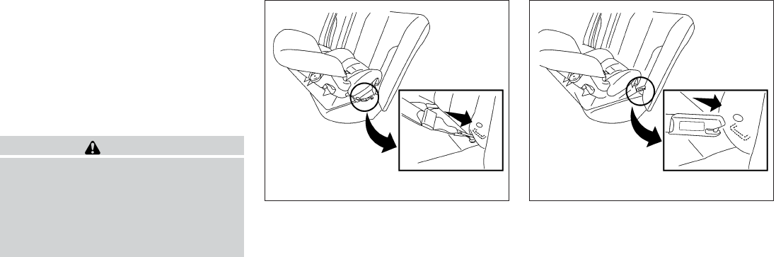
REAR-FACING CHILD RESTRAINT
INSTALLATION USING LATCH
Refer to all Warnings and Cautions in the “Child
Safety” and “Child Restraint” sections before in-
stalling a child restraint.
Follow these steps to install a rear-facing child
restraint in the 2nd row seats using the LATCH
system:
WARNING
Child restraint anchorages are designed
to withstand only those loads imposed by
correctly fitted child restraints. Under no
circumstances are they to be used for
adult seat belts, harnesses or for attach-
ing other items or equipment to the
vehicle.
1. Position the child restraint on the seat. Al-
ways follow the child restraint manufactur-
er’s instructions.
2. Secure the child restraint anchor attach-
ments to the LATCH lower anchors. Check
to make sure the LATCH attachment is prop-
erly attached to the lower anchors.
Rear-facing web-mounted – step 2
WRS0801
Rear-facing rigid-mounted – step 2
WRS0802
1-38 Safety—Seats, seat belts and supplemental restraint system
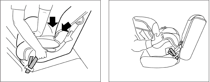
3. For child restraints that are equipped with
webbing-mounted attachments, remove any
additional slack from the anchor attach-
ments. Press downward and rearward firmly
in the center of the child restraint with your
hand to compress the vehicle seat cushion
and seatback while tightening the webbing
of the anchor attachments.
4. After attaching the child restraint, test it be-
fore you place the child in it. Push it from side
to side while holding the child restraint near
the LATCH attachment path. The child re-
straint should not move more than 1 inch
(25 mm), from side to side. Try to tug it
forward and check to see if the LATCH at-
tachment holds the restraint in place. If the
restraint is not secure, tighten the LATCH
attachment as necessary, or put the restraint
in another seat and test it again. You may
need to try a different child restraint or try
installing by using the vehicle seat belt (if
applicable). Not all child restraints fit in all
types of vehicles.
5. Check to make sure the child restraint is
properly secured prior to each use. If the
child restraint is loose, repeat steps 2
through 4.
Rear-facing – step 3
LRS0673
Rear-facing – step 4
LRS0674
Safety—Seats, seat belts and supplemental restraint system 1-39

REAR-FACING CHILD RESTRAINT
INSTALLATION USING THE SEAT
BELTS
WARNING
The three-point seat belt with Automatic
Locking Retractor (ALR) must be used
when installing a child restraint. Failure to
use the ALR mode will result in the child
restraint not being properly secured. The
restraint could tip over or be loose and
cause injury to a child in a sudden stop or
collision. Also, it can change the operation
of the front passenger air bag. See “Front
passenger air bag and status light” later in
this section.
Refer to all Warnings and Cautions in the “Child
safety” and “Child restraints” sections before in-
stalling a child restraint.
Follow these steps to install a rear-facing child
restraint using the vehicle seat belts in the rear
seats:
1. Child restraints for infants must be
used in the rear-facing direction and
therefore must not be used in the front
seat. Position the child restraint on the seat.
Always follow the restraint manufacturer’s
instructions.
WRS0256
Rear-facing – step 1
WRS0256
1-40 Safety—Seats, seat belts and supplemental restraint system

2. Route the seat belt tongue through the child
restraint and insert it into the buckle until you
hear and feel the latch engage. Be sure to
follow the child restraint manufacturer’s in-
structions for belt routing.
3. Pull the shoulder belt until the belt is fully
extended. At this time, the seat belt retractor
is in the Automatic Locking Retractor (ALR)
mode (child restraint mode). It reverts to the
Emergency Locking Retractor (ELR) mode
when the seat belt is fully retracted.
4. Allow the seat belt to retract. Pull up on the
shoulder belt to remove any slack in the belt.
Rear-facing – step 2
WRS0761
Rear-facing – step 3
LRS0669
Rear-facing – step 4
LRS0670
Safety—Seats, seat belts and supplemental restraint system 1-41

5. Remove any additional slack from the seat
belt; press downward and rearward firmly in
the center of the child restraint to compress
the vehicle seat cushion and seatback while
pulling up on the seat belt.
6. After attaching the child restraint, test it be-
fore you place the child in it. Push it from side
to side while holding the child restraint near
the seat belt path. The child restraint should
not move more than 1 in (25 mm), from side
to side. Try to tug it forward and check to see
if the belt holds the restraint in place. If the
restraint is not secure, tighten the seat belt
as necessary, or put the restraint in another
seat and test it again. You may need to try a
different child restraint. Not all child re-
straints fit in all types of vehicles.
7. Check to make sure that the child restraint is
properly secured prior to each use. If the
seat belt is not locked, repeat steps 1
through 6.
After the child restraint is removed and the seat
belt fully retracted, the ALR mode (child restraint
mode) is canceled.
FORWARD-FACING CHILD
RESTRAINT INSTALLATION USING
LATCH
Refer to all Warnings and Cautions in the “Child
Safety” and “Child Restraints” sections before
installing a child restraint.
Follow these steps to install a forward-facing
child restraint in the 2nd row seats using the
LATCH system:
1. Position the child restraint on the seat. Al-
ways follow the child restraint manufactur-
er’s instructions.
Rear-facing – step 5
WRS0762
Rear-facing – step 6
WRS0763
1-42 Safety—Seats, seat belts and supplemental restraint system

2. Secure the child restraint anchor attach-
ments to the LATCH lower anchors. Check
to make sure the LATCH attachment is prop-
erly attached to the lower anchors.
If the child restraint is equipped with a top
tether strap, route the top tether strap and
secure the tether strap to the tether anchor
point. See “Installing top tether strap” in this
section. Do not install child restraints that
require the use of a top tether strap in seat-
ing positions that do not have a top tether
anchor.
3. The back of the child restraint should be
secured against the vehicle seatback.
If necessary, adjust or remove the head
restraint/headrest to obtain the correct child
restraint fit. If the head restraint/headrest is
removed, store it in a secure place. Be sure
to reinstall the head restraint/headrest
when the child restraint is removed.
See “Head restraints/headrests” in this sec-
tion for head restraint/headrest adjustment
information.
If the seating position does not have an
adjustable head restraint/headrest and it is
interfering with the proper child restraint fit,
try another seating position or a different
child restraint.
Forward-facing web-mounted – step 2
WRS0799
Forward-facing rigid-mounted – step 2
WRS0800
Safety—Seats, seat belts and supplemental restraint system 1-43

4. For child restraints that are equipped with
webbing-mounted attachments, remove any
additional slack from the anchor attach-
ments. Press downward and rearward firmly
in the center of the child restraint with your
knee to compress the vehicle seat cushion
and seatback while tightening the webbing
of the anchor attachments.
5. Tighten the tether strap according to the
manufacturer’s instructions to remove any
slack.
6. After attaching the child restraint, test it be-
fore you place the child in it. Push it from side
to side while holding the child restraint near
the LATCH attachment path. The child re-
straint should not move more than 1 inch
(25 mm), from side to side. Try to tug it
forward and check to see if the LATCH at-
tachment holds the restraint in place. If the
restraint is not secure, tighten the LATCH
attachment as necessary, or put the restraint
in another seat and test it again. You may
need to try a different child restraint. Not all
child restraints fit in all types of vehicles.
7. Check to make sure the child restraint is
properly secured prior to each use. If the
child restraint is loose, repeat steps 3
through 6.
FORWARD-FACING CHILD
RESTRAINT INSTALLATION USING
THE SEAT BELTS
WARNING
The three-point seat belt with Automatic
Locking Retractor (ALR) must be used
when installing a child restraint. Failure to
use the ALR mode will result in the child
restraint not being properly secured. The
restraint could tip over or be loose and
cause injury to a child in a sudden stop or
collision. Also, it can change the operation
of the front passenger air bag. See “Front
passenger air bag and status light” later in
this section.
Forward-facing – step 4
LRS0671
Forward-facing – step 6
WRS0697
1-44 Safety—Seats, seat belts and supplemental restraint system

Refer to all Warnings and Cautions in the “Child
Safety” and “Child Restraint” sections before in-
stalling a child restraint.
Follow these steps to install a forward-facing
child restraint using the vehicle seat belt in the
rear seats or in the front passenger seat:
1. If you must install a child restraint in
the front seat, it should be placed in a
forward-facing direction only. Move
the seat to the rearmost position. Child
restraints for infants must be used in
the rear-facing direction and, there-
fore, must not be used in the front seat.
2. Position the child restraint on the seat. Al-
ways follow the child restraint manufactur-
er’s instructions.
The back of the child restraint should be
secured against the vehicle seatback.
If necessary, adjust or remove the head
restraint/headrest to obtain the correct child
restraint fit. If the head restraint/headrest is
removed, store it in a secure place. Be sure
to reinstall the head restraint/headrest
when the child restraint is removed.
See “Head restraints/headrests” in this sec-
tion for head restraint/headrest adjustment,
removal and installation information.
If the seating position does not have an
adjustable head restraint/headrest and it is
interfering with the proper child restraint fit,
try another seating position or a different
child restraint.
3. Route the seat belt tongue through the child
restraint and insert it into the buckle until you
hear and feel the latch engage. Be sure to
follow the child restraint manufacturer’s in-
structions for belt routing.
If the child restraint is equipped with a top
tether strap, route the top tether strap and
secure the tether strap to the tether anchor
point (rear seat installation only). See “In-
stalling top tether strap” in this section. Do
not install child restraints that require the use
of a top tether strap in seating positions that
do not have a top tether anchor.
Forward-facing (front passenger seat) –
step 1
WRS0699
Forward-facing – step 3
WRS0680
Safety—Seats, seat belts and supplemental restraint system 1-45

4. Pull the shoulder belt until the belt is fully
extended. At this time, the seat belt retractor
is in the Automatic Locking Retractor (ALR)
mode (child restraint mode). It reverts to
Emergency Locking Retractor (ELR) mode
when the seat belt is fully retracted.
5. Allow the seat belt to retract. Pull up on the
shoulder belt to remove any slack in the belt.
6. Remove any additional slack from the seat
belt; press downward and rearward firmly in
the center of the child restraint with your
knee to compress the vehicle seat cushion
and seatback while pulling up on the seat
belt.
7. Tighten the tether strap according to the
manufacturer’s instructions to remove any
slack.
Forward-facing – step 4
LRS0667
Forward-facing – step 5
LRS0668
Forward-facing – step 6
WRS0681
1-46 Safety—Seats, seat belts and supplemental restraint system
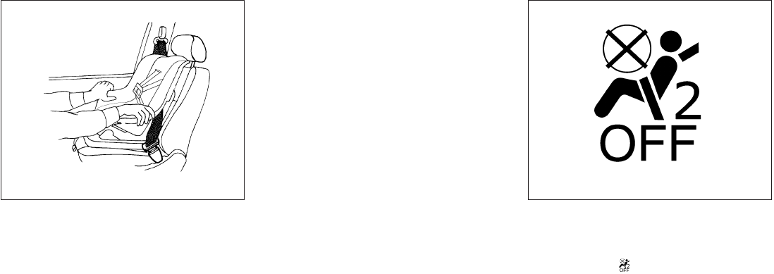
8. After attaching the child restraint, test it be-
fore you place the child in it. Push it from side
to side while holding the child restraint near
the seat belt path. The child restraint should
not move more than 1 in (25 mm), from side
to side. Try to tug it forward and check to see
if the belt holds the restraint in place. If the
restraint is not secure, tighten the seat belt
as necessary, or put the restraint in another
seat and test it again. You may need to try a
different child restraint. Not all child re-
straints fit in all types of vehicles.
9. Check to make sure the child restraint is
properly secured prior to each use. If the
seat belt is not locked, repeat steps 2
through 8.
10. If the child restraint is installed in the front
passenger seat, place the ignition switch in
the ON position. The front passenger air bag
status light should illuminate. If this
light is not illuminated see “Front passenger
air bag and status light” in this section.
Move the child restraint to another
seating position. Have the system
checked by a INFINITI retailer.
After the child restraint is removed and the seat
belt is fully retracted, the ALR mode (child re-
straint mode) is canceled.
Forward-facing – step 8
WRS0698
Forward-facing – step 10
LRS0865
Safety—Seats, seat belts and supplemental restraint system 1-47
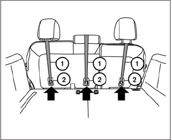
1. Top tether strap
2. Anchor point
INSTALLING TOP TETHER STRAP
(2nd row bench seat)
First, secure the child restraint with the LATCH
lower anchors (2nd row bench outboard seating
positions only) or the seat belt, as applicable.
1. OUTBOARD SEATING POSITIONS
If necessary, raise or remove the head
restraint/headrest to position the top tether
strap 䊊
1over the top of the seatback. If the
head restraint/headrest is removed, store it
in a secure place. Be sure to reinstall the
head restraint/headrest when the child re-
straint is removed. See “Head
restraint/headrest adjustment” in this
section for head restraint/headrest ad-
justment, removal and installation in-
formation.
CENTER SEATING POSITION
Remove the head restraint/headrest and po-
sition the top tether strap 䊊
1over the seat-
back or adjust the head restraint/headrest to
the lowest position and position the top
tether strap over the head
restraint/headrest. If the head
restraint/headrest is removed, store it in a
secure place. Be sure to reinstall the head
restraint/headrest when the child restraint is
removed. See “head restraint/headrest”
in this section for head
restraint/headrest adjustment, re-
moval and installation information.
2. Secure the tether strap to the tether anchor
point 䊊
2on the bottom of the seatback
behind the child restraint.
3. Tighten the tether strap according to the
manufacturer’s instructions to remove any
slack. Make sure the head restraint/headrest
does not contact the top tether strap.
If you have any questions when installing a
top tether strap, consult your INFINITI re-
tailer for details.
2nd row bench seat
LRS2138
1-48 Safety—Seats, seat belts and supplemental restraint system

1. Top tether strap
2. Anchor point
INSTALLING TOP TETHER STRAP
(3rd row bench seat)
WARNING
In the 3rd row bench seat, a child restraint
with a top tether strap can only be used on
the passenger side seating position. Do
not place in the driver’s side seating posi-
tion and attempt to angle the tether strap
to the passenger side seating position.
The passenger side of the 3rd row bench seat is
the seating position that can use a top tether
strap.
First, secure the child restraint with the seat belt,
as applicable.
1. Position the top tether strap 䊊
1to the out-
board side of the head restraint/headrest as
shown.
2. Secure the tether strap to the tether anchor
point 䊊
2on the bottom of the seatback
behind the child restraint.
3. Tighten the tether strap according to the
manufacturer’s instructions to remove any
slack. Make sure the head restraint/headrest
does not contact the top tether strap.
If you have any questions when installing a
top tether strap, consult your INFINITI re-
tailer for details.
BOOSTER SEATS
Precautions on booster seats
WARNING
If a booster seat and seat belt are not used
properly, the risk of a child being injured in
a sudden stop or collision greatly
increases:
– Make sure the shoulder portion of
the belt is away from the child’s face
and neck and the lap portion of the
belt does not cross the stomach.
– Make sure the shoulder belt is not
behind the child or under the child’s
arm.
– A booster seat must only be installed
in a seating position that has a
lap/shoulder belt.
3rd row bench seat
LRS2291
Safety—Seats, seat belts and supplemental restraint system 1-49

Booster seats of various sizes are offered by
several manufacturers. When selecting any
booster seat, keep the following points in mind:
●Choose only a booster seat with a label
certifying that it complies with Federal Motor
Vehicle Safety Standard 213 or Canadian
Motor Vehicle Safety Standard 213.
●Check the booster seat in your vehicle to be
sure it is compatible with the vehicle’s seat
and seat belt system.
LRS0455 LRS0453 LRS0464
1-50 Safety—Seats, seat belts and supplemental restraint system

●Make sure the child’s head will be properly
supported by the booster seat or vehicle
seat. The seatback must be at or above the
center of the child’s ears. For example, if a
low back booster seat 䊊
1is chosen, the
vehicle seatback must be at or above the
center of the child’s ears. If the seatback is
lower than the center of the child’s ears, a
high back booster seat 䊊
2should be used.
●If the booster seat is compatible with your
vehicle, place the child in the booster seat
and check the various adjustments to be
sure the booster seat is compatible with the
child. Always follow all recommended pro-
cedures.
All U.S. states and Canadian provinces or
territories require that infants and small
children be restrained in an approved child
restraint at all times while the vehicle is
being operated.
The instructions in this section apply to booster
seat installation in the rear seats or the front
passenger seat.
Booster seat installation
CAUTION
Do not use the lap/shoulder belt in the
Automatic Locking Retractor mode when
using a booster seat with the seat belts.
Refer to all Warnings and Cautions in the “Child
Safety”, “Child Restraint” and “Booster Seats”
sections before installing a child restraint.
Follow these steps to install a booster seat in the
rear seat or in the front passenger seat:
1. If you must install a booster seat in the
front seat, move the seat to the rear-
most position.
2. Position the booster seat on the seat. Only
place it in a front-facing direction. Always
follow the booster seat manufacturer’s in-
structions.
WRS0699
Safety—Seats, seat belts and supplemental restraint system 1-51
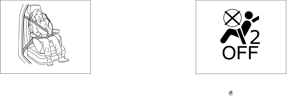
3. The booster seat should be positioned on
the vehicle seat so that it is stable.
If necessary, adjust or remove the head
restraint/headrest to obtain the correct
booster seat fit. If the head
restraint/headrest is removed, store it in a
secure place. Be sure to reinstall the
head restraint/headrest when the
booster seat is removed. See “Head
restraints/headrests” in this section for head
restraint/headrest adjustment, removal and
installation information.
If the seating position does not have an
adjustable head restraint/headrest and it is
interfering with the proper booster seat fit,
try another seating position or a different
booster seat.
4. Position the lap portion of the seat belt low
and snug on the child’s hips. Be sure to
follow the booster seat manufacturer’s in-
structions for adjusting the seat belt routing.
5. Pull the shoulder belt portion of the seat belt
toward the retractor to take up extra slack.
Be sure the shoulder belt is positioned
across the top, middle portion of the child’s
shoulder. Be sure to follow the booster seat
manufacturer’s instructions for adjusting the
seat belt routing.
6. Follow the warnings, cautions and instruc-
tions for properly fastening a seat belt
shown in “Three-point type seat belt with
retractor” earlier in this section.
7. If the booster seat is installed in the front
passenger seat, place the ignition switch in
the ON position. The front passenger air bag
status light may or may not illuminate,
depending on the size of the child and the
type of booster seat being used. See “Front
passenger air bag and status light” later in
this section.
Front passenger position
LRS0454 LRS0865
1-52 Safety—Seats, seat belts and supplemental restraint system
PRECAUTIONS ON SUPPLEMENTAL
RESTRAINT SYSTEM
This Supplemental Restraint System (SRS) sec-
tion contains important information concerning
the following systems:
●Driver and passenger supplemental front-
impact air bag (INFINITI Advanced Air Bag
System)
●Front seat-mounted side-impact supple-
mental air bag
●Roof-mounted curtain side-impact and roll-
over supplemental air bag
●Seat belt with pretensioner
Supplemental front- impact air bag system:
The INFINITI Advanced Air Bag System can help
cushion the impact force to the head and chest of
the driver and front passenger in certain frontal
collisions.
Front seat-mounted side-impact supple-
mental air bag system: This system can help
cushion the impact force to the chest area of the
driver and front passenger in certain side-impact
collisions. The side air bags are designed to
inflate on the side where the vehicle is impacted.
Roof-mounted curtain side-impact and
rollover supplemental air bag system: This
system can help cushion the impact force to the
head of occupants in front and rear outboard
seating positions in certain side-impact or roll-
over collisions. In a side impact, the curtain air
bags are designed to inflate on the side where
the vehicle is impacted. In a rollover, the curtain
air bags are designed to inflate and remain in-
flated for a short time.
These supplemental restraint systems are de-
signed to supplement the crash protection pro-
vided by the driver and front passenger seat belts
and are not a substitute for them. Seat belts
should always be correctly worn and the occu-
pant seated a suitable distance away from the
steering wheel, instrument panel and door finish-
ers. See “Seat belts” earlier in this section for
instructions and precautions on seat belt usage.
The supplemental air bags operate only
when the ignition switch is placed in the ON
position.
After placing the ignition switch in the ON
position, the supplemental air bag warning
light illuminates. The supplemental air bag
warning light will turn off after about 7 sec-
onds if the system is operational.
SUPPLEMENTAL RESTRAINT
SYSTEM
Safety—Seats, seat belts and supplemental restraint system 1-53

WARNING
●The front air bags ordinarily will not
inflate in the event of a side impact, rear
impact, rollover, or lower severity fron-
tal collision. Always wear your seat
belts to help reduce the risk or severity
of injury in various kinds of accidents.
●The front passenger air bag will not
inflate if the passenger air bag status
light is lit or if the front passenger seat
is unoccupied. See “Front passenger air
bag and status light” later in this
section.
●The seat belts and the front air bags are
most effective when you are sitting well
back and upright in the seat. The front
air bags inflate with great force. Even
with the INFINITI Advanced Air Bag Sys-
tem, if you are unrestrained, leaning
forward, sitting sideways or out of posi-
tion in any way, you are at greater risk of
injury or death in a crash. You may also
receive serious or fatal injuries from the
front air bag if you are up against it
when it inflates. Always sit back against
the seatback and as far away as practi-
cal from the steering wheel or instru-
ment panel. Always use the seat belts.
●The driver and front passenger seat belt
buckles are equipped with sensors that
detect if the seat belts are fastened. The
Advanced Air Bag System monitors the
severity of a collision and seat belt us-
age then inflates the air bags as
needed. Failure to properly wear seat
belts can increase the risk or severity of
injury in an accident.
●The front passenger seat is equipped
with an Occupant Classification Sensor
(weight sensor) that turns the front pas-
senger air bag OFF under some condi-
tions. This sensor is only used in this
seat. Failure to be properly seated and
wearing the seat belt can increase the
risk or severity of injury in an accident.
See “Front passenger air bag and sta-
tus light” later in this section.
●Keep hands on the outside of the steer-
ing wheel. Placing them inside the
steering wheel rim could increase the
risk that they are injured when the front
air bag inflates.
WRS0031
1-54 Safety—Seats, seat belts and supplemental restraint system

WARNING
●Never let children ride unrestrained or
extend their hands or face out of the
window. Do not attempt to hold them in
your lap or arms. Some examples of
dangerous riding positions are shown
in the illustrations.
ARS1133 ARS1041
Safety—Seats, seat belts and supplemental restraint system 1-55

ARS1042 ARS1043 ARS1044
1-56 Safety—Seats, seat belts and supplemental restraint system

WARNING
●Children may be severely injured or
killed when the front air bags, side air
bags or curtain air bags inflate if they
are not properly restrained. Pre-teens
and children should be properly re-
strained in the rear seat, if possible.
●Even with the INFINITI Advanced Air
Bag System, never install a rear-facing
child restraint in the front seat. An in-
flating front air bag could seriously in-
jure or kill your child. See “Child re-
straints” earlier in this section for
details.
WARNING
Front seat-mounted side-impact supple-
mental air bags and roof-mounted curtain
side-impact supplemental air bags:
●The side air bags and curtain air bags
ordinarily will not inflate in the event of
a frontal impact, rear impact, or lower
severity side collision. Always wear
your seat belts to help reduce the risk or
severity of injury in various kinds of
accidents.
ARS1045 ARS1046 WRS0431
Safety—Seats, seat belts and supplemental restraint system 1-57

WARNING
●The seat belts, the side air bags and
curtain air bags are most effective when
you are sitting well back and upright in
the seat with both feet on the floor. The
side air bag and curtain air bag inflate
with great force. Do not allow anyone to
place their hand, leg or face near the
side air bag on the side of the seatback
of the front seat or near the side roof
rails. Do not allow anyone sitting in the
front seats or rear outboard seats to
extend their hand out of the window or
lean against the door. Some examples
of dangerous riding positions are
shown in the previous illustrations.
WRS0365 SSS0162
1-58 Safety—Seats, seat belts and supplemental restraint system

WARNING
●When sitting in the 2nd row rear seat, do
not hold onto the seatback of the front
seat. If the side air bag inflates, you may
be seriously injured. Be especially care-
ful with children, who should always be
properly restrained. Some examples of
dangerous riding positions are shown
in the illustrations.
●Do not use seat covers on the front
seatbacks. They may interfere with side
air bag inflation.
WRS0363 SSS0159
Safety—Seats, seat belts and supplemental restraint system 1-59

1. Roof-mounted curtain side-impact and
rollover supplemental air bag inflators
2. Roof-mounted curtain side-impact and
rollover supplemental air bags
3. Air bag Control Unit (ACU)
4 Pressure sensors in door (driver’s side
shown; passenger side similar)
5. Supplemental front-impact air bag mod-
ules
6. Crash zone sensor
7. Occupant classification system control
unit
8. Occupant classification sensor (weight
sensor – located on passenger seat
frame )
9. Satellite sensors
10. Seat belt with pretensioner
11. Front seat-mounted side-impact
supplemental air bag modules
LRS2141
1-60 Safety—Seats, seat belts and supplemental restraint system

INFINITI Advanced Air Bag System
(front seats)
WARNING
To ensure proper operation of the passen-
ger’s advanced air bag system, please ob-
serve the following items.
●Do not allow a passenger in the rear
seat to push or pull on the seatback
pocket.
●Do not place heavy loads heavier than
2.2 lb (1 kg) on the seatback, head
restraint/headrest or in the seatback
pocket.
●Do not store luggage behind the seat
that can press into the seatback.
●Do not position the front passenger
seat so it contacts the rear seat. If the
front seat does contact the rear seat,
the air bag system may determine a
sensor malfunction has occurred and
the front passenger air bag status light
may illuminate and the supplemental
air bag warning light may flash.
●If a forward-facing child restraint is in-
stalled in the front passenger seat, do
not position the front passenger seat so
the child restraint contacts the instru-
ment panel. If the child restraint does
contact the instrument panel, the sys-
tem may determine the seat is occupied
and the passenger air bag may deploy
in a collision. Also the front passenger
air bag status light may not illuminate.
See “Child restraints” earlier in this sec-
tion for information about installing
and using child restraints.
●Confirm the operating condition with
the front passenger air bag status light.
●If you notice that the front passenger air
bag status light is not operating as de-
scribed later in this section, please take
your vehicle to your INFINITI retailer to
check the occupant classification
system.
●Until you have confirmed with your re-
tailer that your passenger seat occu-
pant classification system is working
properly, position the occupants in the
rear seating positions.
This vehicle is equipped with the INFINITI Ad-
vanced Air Bag System for the driver and front
passenger seats. This system is designed to
meet certification requirements under U.S. regu-
lations. It is also permitted in Canada. However,
all of the information, cautions and warn-
ings in this manual still apply and must be
followed.
The driver supplemental front-impact air bag is
located in the center of the steering wheel. The
passenger supplemental front-impact air bag is
mounted in the dashboard above the glove box.
The front air bags are designed to inflate in higher
severity frontal collisions, although they may in-
flate if the forces in another type of collision are
similar to those of a higher severity frontal impact.
They may not inflate in certain frontal collisions.
Vehicle damage (or lack of it) is not always an
indication of proper front air bag system opera-
tion.
The INFINITI Advanced Air Bag System has dual
stage inflators. It also monitors information from
the crash zone sensor, the Air bag Control Unit
(ACU), seat belt buckle sensor and Occupant
Classification Sensor (weight sensor). Inflator
operation is based on the severity of a collision
and seat belt usage for the driver. For the front
passenger, the occupant classification sensor is
also monitored. Based on information from the
sensor, only one front air bag may inflate in a
Safety—Seats, seat belts and supplemental restraint system 1-61
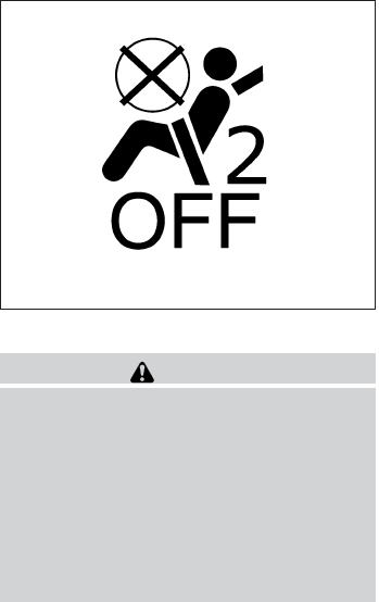
crash, depending on the crash severity and
whether the front occupants are belted or un-
belted. Additionally, the front passenger air bag
may be automatically turned OFF under some
conditions, depending on the weight detected on
the passenger seat and how the seat belt is used.
If the front passenger air bag is OFF, the passen-
ger air bag status light will be illuminated (if the
seat is unoccupied, the light will not be illumi-
nated, but the air bag will be off). See “Front
passenger air bag and status light” later in this
section for further details. One front air bag inflat-
ing does not indicate improper performance of
the system.
If you have any questions about your air bag
system, please contact INFINITI or your INFINITI
retailer. If you are considering modification of
your vehicle due to a disability, you may also
contact INFINITI. Contact information is con-
tained in the front of this Owner’s Manual.
When a front air bag inflates, a fairly loud noise
may be heard, followed by the release of smoke.
This smoke is not harmful and does not indicate a
fire. Care should be taken to not inhale it, as it may
cause irritation and choking. Those with a history
of a breathing condition should get fresh air
promptly.
Front air bags, along with the use of seat belts,
help to cushion the impact force on the face and
chest of the front occupants. They can help save
lives and reduce serious injuries. However, an
inflating front air bag may cause facial abrasions
or other injuries. Front air bags do not provide
restraint to the lower body.
Even with INFINITI advanced air bags, seat belts
should be correctly worn and the driver and pas-
senger seated upright as far as practical away
from the steering wheel or instrument panel. The
front air bags inflate quickly in order to help
protect the front occupants. Because of this, the
force of the front air bag inflating can increase the
risk of injury if the occupant is too close to, or is
against, the front air bag module during inflation.
The front air bags deflate quickly after a collision.
The front air bags operate only when the
ignition switch is placed in the ON position.
After placing the ignition switch in the ON
position, the supplemental air bag warning
light illuminates. The supplemental air bag
warning light will turn off after about 7 sec-
onds if the system is operational.
Front passenger air bag and status light
WARNING
The front passenger air bag is designed to
automatically turn OFF under some condi-
tions. Read this section carefully to learn
how it operates. Proper use of the seat,
seat belt and child restraints is necessary
for most effective protection. Failure to
follow all instructions in this manual con-
cerning the use of seats, seat belts and
child restraints can increase the risk or
severity of injury in an accident.
LRS0865
1-62 Safety—Seats, seat belts and supplemental restraint system

Status light
The front passenger air bag status light is
located near the radio controls. After the ignition
switch is placed in the ⬙ON⬙position, the front
passenger air bag status light on the instrument
panel illuminates for about 7 seconds and then
turns off or remains illuminated depending on the
front passenger seat occupied status. The light
operates as follows:
●Unoccupied passenger’s seat: The is
OFF and the front passenger air bag is OFF
and will not inflate in a crash.
●Passenger’s seat occupied by a small adult,
child or child restraint as outlined in this
section: The illuminates to indicate
that the front passenger air bag is OFF and
will not inflate in a crash.
●Occupied passenger seat and the passen-
ger meets the conditions outlined in this
section: The light is OFF to indicate
that the front passenger air bag is opera-
tional.
Front passenger air bag
The front passenger air bag is designed to auto-
matically turn OFF when the vehicle is operated
under some conditions as described below in
accordance with U.S. regulations. If the front
passenger air bag is OFF, it will not inflate in a
crash. The driver air bag and other air bags in your
vehicle are not part of this system.
The purpose of the regulation is to help reduce
the risk of injury or death from an inflating air bag
to certain front passenger seat occupants, such
as children, by requiring the air bag to be auto-
matically turned OFF. Certain sensors are used to
meet the requirements.
The occupant classification sensor in this vehicle
is a weight sensor. It is designed to detect an
occupant and objects on the seat by weight. For
example, if a child is in the front passenger seat,
the Advanced Air Bag System is designed to turn
the passenger air bag OFF in accordance with
the regulations. Also, if a child restraint of the type
specified in the regulations is on the seat, its
weight and the child’s weight can be detected
and cause the air bag to turn OFF.
Front passenger seat adult occupants who are
properly seated and using the seat belt as out-
lined in this manual should not cause the passen-
ger air bag to be automatically turned OFF. For
small adults it may be turned OFF, however if the
occupant takes his/her weight off the seat cush-
ion (for example, by not sitting upright, by sitting
on an edge of the seat, or by otherwise being out
of position), this could cause the sensor to turn
the air bag OFF. Always be sure to be seated and
wearing the seat belt properly for the most effec-
tive protection by the seat belt and supplemental
air bag.
INFINITI recommends that pre-teens and chil-
dren be properly restrained in a rear seat.
INFINITI also recommends that appropriate child
restraints and booster seats be properly installed
in a rear seat. If this is not possible, the occupant
classification sensor is designed to operate as
described above to turn the front passenger air
bag OFF for specified child restraints as required
by the regulations. Failing to properly secure
child restraints and to use the ALR mode may
allow the restraint to tip or move in an accident or
sudden stop. This can also result in the passen-
ger air bag inflating in a crash instead of being
OFF. See “Child restraints” earlier in this section
for proper use and installation.
If the front passenger seat is not occupied, the
passenger air bag is designed not to inflate in a
crash. However, heavy objects placed on the
seat could result in air bag inflation, because of
the object’s weight detected by the occupant
classification sensor. Other conditions could also
result in air bag inflation, such as if a child is
standing on the seat, or if two children are on the
seat, contrary to the instructions in this manual.
Always be sure that you and all vehicle occupants
are seated and restrained properly.
Safety—Seats, seat belts and supplemental restraint system 1-63

Using the passenger air bag status light, you can
monitor when the front passenger air bag is au-
tomatically turned OFF with the seat occupied.
The light will not illuminate when the front pas-
senger seat is unoccupied.
If an adult occupant is in the seat but the passen-
ger air bag status light is illuminated (indicating
that the air bag is OFF), it could be that the
person is a small adult, or is not sitting on the seat
properly or not using the seat belt properly.
If a child restraint must be used in the front seat,
the passenger air bag status light may or may not
be illuminated, depending on the size of the child
and the type of child restraint being used. If the air
bag status light is not illuminated (indicating that
the air bag might inflate in a crash), it could be
that the child restraint or seat belt is not being
used properly. Make sure that the child restraint is
installed properly, the seat belt is used properly
and the occupant is positioned properly. If the air
bag status light is not illuminated, reposition the
occupant or child restraint in a rear seat.
If the passenger air bag status light will not illu-
minate even though you believe that the child
restraint, the seat belts and the occupant are
properly positioned, the system may be sensing
an unoccupied seat (in which case the air bag is
OFF). Your INFINITI retailer can check that the
system is OFF by using a special tool. However,
until you have confirmed with your retailer that
your air bag is working properly, reposition the
occupant or child restraint in a rear seat.
The air bag system and passenger air bag status
light will take a few seconds to register a change
in the passenger seat status. For example, if a
large adult who is sitting in the front passenger
seat exits the vehicle, the passenger air bag
status light will go from OFF to ON for a few
seconds and then to OFF. This is normal system
operation and does not indicate a malfunction.
If a malfunction occurs in the front passenger air
bag system, the supplemental air bag warning
light , located in the meter and gauges area
of the instrument panel, will blink. Have the sys-
tem checked by a INFINITI retailer.
Other supplemental front-impact air bag
precautions
WARNING
●Do not place any objects on the steering
wheel pad or on the instrument panel.
Also, do not place any objects between
any occupant and the steering wheel or
instrument panel. Such objects may be-
come dangerous projectiles and cause
injury if the front air bags inflate.
●Do not place objects with sharp edges
on the seat. Also, do not place heavy
objects on the seat that will leave per-
manent impressions in the seat. Such
objects can damage the seat or occu-
pant classification sensors (weight sen-
sors). This can affect the operation of
the air bag system and result in serious
personal injury.
●Do not use water or acidic cleaners (hot
steam cleaners) on the seat. This can
damage the seat or occupant classifica-
tion sensors. This can also affect the
operation of the air bag system and
result in serious personal injury.
●Immediately after inflation, several
front air bag system components will be
hot. Do not touch them; you may se-
verely burn yourself.
●No unauthorized changes should be
made to any components or wiring of
the supplemental air bag system. This is
to prevent accidental inflation of the
supplemental air bag or damage to the
supplemental air bag system.
1-64 Safety—Seats, seat belts and supplemental restraint system

●Do not make unauthorized changes to
your vehicle’s electrical system, sus-
pension system or front end structure.
This could affect proper operation of
the front air bag system.
●Tampering with the front air bag system
may result in serious personal injury.
Tampering includes changes to the
steering wheel and the instrument
panel assembly by placing material
over the steering wheel pad and above
the instrument panel or by installing
additional trim material around the air
bag system.
●Removing or modifying the front pas-
senger seat may affect the function of
the air bag and result in serious per-
sonal injury.
●Modifying or tampering with the front
passenger seat may result in serious
personal injury. For example, do not
change the front seats by placing mate-
rial on the seat cushion or by installing
additional trim material, such as seat
covers, on the seat that are not specifi-
cally designed to assure proper air bag
operation. Additionally, do not stow any
objects under the front passenger seat
or the seat cushion and seatback. Such
objects may interfere with the proper
operation of the occupant classification
sensor (weight sensor).
●No unauthorized changes should be
made to any components or wiring of
the seat belt system. This may affect the
front air bag system. Tampering with
the seat belt system may result in seri-
ous personal injury.
●Work on and around the front air bag
system should be done by a INFINITI
retailer. Installation of electrical equip-
ment should also be done by a INFINITI
retailer. The Supplemental Restraint
System (SRS) wiring harnesses* should
not be modified or disconnected. Unau-
thorized electrical test equipment and
probing devices should not be used on
the air bag system.
●A cracked windshield should be re-
placed immediately by a qualified repair
facility. A cracked windshield could af-
fect the function of the supplemental air
bag system.
*The SRS wiring harness connectors are
yellow and orange for easy identification.
When selling your vehicle, we request that you
inform the buyer about the front air bag system
and guide the buyer to the appropriate sections
in this Owner’s Manual.
Safety—Seats, seat belts and supplemental restraint system 1-65
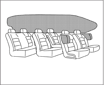
Front seat-mounted side-impact
supplemental air bag and roof-
mounted curtain side-impact and
rollover supplemental air bag systems
The side air bags are located in the outside of the
seatback of the front seats. The curtain air bags
are located in the side roof rails in all 3 rows. All
of the information, cautions and warnings
in this manual must be followed. The side air
bags and curtain air bags are designed to inflate
in higher severity side collisions, although they
may inflate if the forces in another type of collision
are similar to those of a higher severity impact.
They are designed to inflate on the side where the
vehicle is impacted. They may not inflate in cer-
tain side collisions.
Curtain air bags are also designed to inflate in
certain types of rollover collisions or near roll-
overs. As a result, certain vehicle movements (for
example, during severe off roading) may cause
the curtain air bags to inflate.
Vehicle damage (or lack of it) is not always an
indication of proper side air bag and curtain air
bag operation.
When the side air bags and curtain air bags
inflate, a fairly loud noise may be heard, followed
by release of smoke. This smoke is not harmful
and does not indicate a fire. Care should be taken
not to inhale it, as it may cause irritation and
choking. Those with a history of a breathing con-
dition should get fresh air promptly.
Side air bags, along with the use of seat belts,
help to cushion the impact force on the chest of
the front occupants. Curtain air bags help to
cushion the impact force to the head of occu-
pants in the front and rear outboard seating po-
sitions in all rows. They can help save lives and
reduce serious injuries. However, an inflating
side air bag or curtain air bag may cause abra-
sions or other injuries. Side air bags and curtain
air bags do not provide restraint to the lower
body.
The seat belts should be correctly worn and the
driver and passenger seated upright as far as
practical away from the side air bag. Rear seat
passengers should be seated as far away as
practical from the door finishers and side roof
rails. The side air bags and curtain air bags inflate
quickly in order to help protect the occupants.
Because of this, the force of the side air bags and
curtain air bags inflating can increase the risk of
injury if the occupant is too close to, or is against,
these air bag modules during inflation. The side
air bag will deflate quickly after the collision is
over.
The curtain air bag will remain inflated for a short
time.
The side air bags and curtain air bags op-
erate only when the ignition switch is
placed in the ON position.
After placing the ignition switch in the ON
position, the supplemental air bag warning
light illuminates. The supplemental air bag
warning light will turn off after about 7 sec-
onds if the system is operational.
WRS0381
1-66 Safety—Seats, seat belts and supplemental restraint system

WARNING
●Do not place any objects near the seat-
back of the front seats. Also, do not
place any objects (an umbrella, bag,
etc.) between the front door finisher
and the front seat. Such objects may
become dangerous projectiles and
cause injury if a side air bag inflates.
●Right after inflation, several side air bag
and curtain air bag system components
will be hot. Do not touch them; you may
severely burn yourself.
●No unauthorized changes should be
made to any components or wiring of
the side air bag and curtain air bag
systems. This is to prevent damage to or
accidental inflation of the side air bag
and curtain air bag systems.
●Do not make unauthorized changes to
your vehicle’s electrical system, sus-
pension system or side panel. This
could affect proper operation of the cur-
tain air bag systems.
●Tampering with the side air bag system
may result in serious personal injury.
For example, do not change the front
seats by placing material near the seat-
backs or by installing additional trim
material, such as seat covers, around
the side air bag.
●Work around and on the side air bag
and curtain air bag systems should be
done by an INFINITI retailer. Installation
of electrical equipment should also be
done by an INFINITI retailer. The SRS
wiring harnesses* should not be modi-
fied or disconnected. Unauthorized
electrical test equipment and probing
devices should not be used on the side
air bag or curtain air bag systems.
* The SRS wiring harness or connectors are
yellow or orange for easy identification.
When selling your vehicle, we request that you
inform the buyer about the side air bags and
curtain air bag system and guide the buyer to the
appropriate sections in this Owner’s Manual.
Seat belts with pretensioners (Front
seats)
WARNING
●If the vehicle becomes involved in a
collision but a pretensioner is not acti-
vated, be sure to have the pretensioner
system checked and, if necessary, re-
placed by your INFINITI retailer.
●No unauthorized changes should be
made to any components or wiring of
the pretensioner system. This is to pre-
vent damage to or accidental activation
of the pretensioners. Tampering with
the pretensioner system may result in
serious personal injury.
●Work around and on the pretensioner
system should be done by an INFINITI
retailer. Installation of electrical equip-
ment should also be done by an
INFINITI retailer. Unauthorized electri-
cal test equipment and probing devices
should not be used on the pretensioner
system.
●If you need to dispose of a pretensioner
or scrap the vehicle, contact an INFINITI
retailer. Incorrect disposal procedures
could cause personal injury.
Safety—Seats, seat belts and supplemental restraint system 1-67

The pretensioner system may activate with the
supplemental air bag system in certain types of
collisions. Working with the seat belt retractor,
the pretensioner helps tighten the seat belt when
the vehicle becomes involved in certain types of
collisions, helping to restrain front seat occu-
pants.
The pretensioner is encased with the seat belt
retractor. These seat belts are used the same way
as conventional seat belts.
When a pretensioner activates, smoke is re-
leased and a loud noise may be heard. This
smoke is not harmful and does not indicate a fire.
Care should be taken not to inhale it, as it may
cause irritation and choking. Those with a history
of a breathing condition should get fresh air
promptly.
After pretensioner activation, load limiters allow
the seat belt to release webbing (if necessary) to
reduce forces against the chest.
The supplemental air bag warning light is
used to indicate malfunctions in the pretensioner
system. (See ⬙SUPPLEMENTAL AIR BAG
WARNING LIGHT⬙in this section for more de-
tails.) If the operation of the supplemental air bag
warning light indicates there is a malfunction,
have the system checked by a INFINITI retailer.
When selling your vehicle, we request that you
inform the buyer about the pretensioner system
and guide the buyer to the appropriate sections
in this Owner’s Manual.
1. SRS Air Bag Warning Labels
The warning labels are located on the sur-
face of the sun visor.
SUPPLEMENTAL AIR BAG
WARNING LABELS
Warning labels about the supplemental front-
impact air bag system are placed in the vehicle as
shown in the illustration.
WARNING
Extreme Hazard! Do not use a rearward
facing child restraint on a seat protected
by an airbag in front of it!
LRS2158
1-68 Safety—Seats, seat belts and supplemental restraint system

SUPPLEMENTAL AIR BAG
WARNING LIGHT
The supplemental air bag warning light,
displaying in the instrument panel, moni-
tors the circuits for the air bag systems, preten-
sioners and all related wiring.
When the ignition switch is placed in the ON
position, the supplemental air bag warning light
illuminates for about 7 seconds and then turns
off. This means the system is operational.
If any of the following conditions occur, the front
air bag, side air bag, curtain air bag and preten-
sioner systems need servicing:
●The supplemental air bag warning light re-
mains on after approximately 7 seconds.
●The supplemental air bag warning light
flashes intermittently.
●The supplemental air bag warning light does
not come on at all.
Under these conditions, the front air bag, side air
bag, curtain air bag or pretensioner systems may
not operate properly. They must be checked and
repaired. Take your vehicle to the nearest
INFINITI retailer.
WARNING
If the supplemental air bag warning light
is on, it could mean that the front air bag,
side air bag, curtain air bag and/or preten-
sioner systems will not operate in an acci-
dent. To help avoid injury to yourself or
others, have your vehicle checked by an
INFINITI retailer as soon as possible.
Repair and replacement procedure
The front air bags, side air bags, curtain air bags
and pretensioners are designed to inflate on a
one-time-only basis. As a reminder, unless it is
damaged, the supplemental air bag warning light
remains illuminated after inflation has occurred.
Repair and replacement of these supplemental
air bag systems should be done only by an
INFINITI retailer.
When maintenance work is required on the ve-
hicle, the front air bags, side air bags, curtain air
bags, pretensioners and related parts should be
pointed out to the person performing the mainte-
nance. The ignition switch should always be in
the LOCK position when working under the hood
or inside the vehicle.
LRS0100
Safety—Seats, seat belts and supplemental restraint system 1-69

WARNING
●Once a front air bag, side air bag, or
curtain air bag has inflated, the air bag
module will not function again and
must be replaced. Additionally, the acti-
vated pretensioners must also be re-
placed. The air bag module and preten-
sioner should be replaced by an
INFINITI retailer. The air bag module
and pretensioner cannot be repaired.
●The front air bag, side air bag, curtain
air bag systems and the pretensioner
system should be inspected by an
INFINITI retailer if there is any damage
to the front end or side portion of the
vehicle.
●If you need to dispose of a supplemen-
tal air bag or pretensioner or scrap the
vehicle, contact an INFINITI retailer. In-
correct disposal procedures could
cause personal injury.
1-70 Safety—Seats, seat belts and supplemental restraint system
MEMO
Safety—Seats, seat belts and supplemental restraint system 1-71
2 Instruments and controls
Instrument panel...................................2-2
Meters and gauges ................................2-4
Speedometer and odometer . . ...................2-4
Tachometer ....................................2-5
Engine coolant temperature gauge ...............2-5
Fuel gauge ....................................2-6
Warning/indicator lights and audible reminders .......2-7
Checking bulbs ................................2-7
Warning lights .................................2-7
Indicator lights ................................2-11
Audible reminders .............................2-13
Vehicle Information Display ........................2-14
How to use the vehicle information display .......2-15
Startup display ................................2-15
Settings ......................................2-15
Vehicle information display warnings and
indicators.....................................2-21
Security systems .................................2-24
Vehicle security system.........................2-24
INFINITI vehicle immobilizer system ..............2-25
Windshield wiper and washer switch ...............2-26
Switch operation ..............................2-27
Rain-sensing auto wiper system
(if so equipped) ...............................2-28
Rear window wiper and washer switch..............2-29
Rear window and outside mirror defroster switch.....2-30
Headlight and turn signal switch....................2-30
Xenon headlights ..............................2-30
Headlight control switch........................2-31
Daytime running light system (Canada only) ......2-33
Instrument brightness control ...................2-34
Turn signal switch .............................2-34
Fog light switch ...............................2-34
Horn ............................................2-35
Heated front seats (if so equipped) .................2-35
Heated rear seats (if so equipped)..................2-36
Climate control seat switch (if so equipped) .........2-38
Heated steering wheel (if so equipped) .............2-39
Warning systems switch (if so equipped)............2-40
Vehicle Dynamic Control (VDC) off switch...........2-40
Power inverter switch (if so equipped) ..............2-41
Power outlets ....................................2-41
12v outlets ...................................2-41
120v outlet (if so equipped) ....................2-43

Storage .........................................2-43
Map pockets..................................2-43
Seatback pockets .............................2-44
Sunglasses holder.............................2-44
Cup holders ..................................2-45
Glove box ....................................2-46
Console box ..................................2-47
Storage tray ..................................2-47
Luggage hooks................................2-48
Cargo area storage bin.........................2-48
Roof rack (if so equipped) ......................2-49
Windows ........................................2-50
Power windows ...............................2-50
Moonroof ........................................2-52
Automatic moonroof ...........................2-52
Panoramic sunshade (if so equipped) ............2-54
Interior light ......................................2-55
Console light..................................2-55
Personal lights ...................................2-56
Map lights .......................................2-56
Cargo light ......................................2-56
HomeLink® universal transceiver (if so equipped) ....2-57
Programming HomeLink® ......................2-58
Programming HomeLink® for Canadian
customers and gate openers....................2-59
Operating the HomeLink® universal
transceiver....................................2-59
Programming trouble-diagnosis .................2-60
Clearing the programmed information ............2-60
Reprogramming a single HomeLink® button......2-60
If your vehicle is stolen .........................2-60

1. Vent (P. 4-46)
2. Headlight/fog light/turn signal switch
(P. 2-30)
3. Instrument brightness control (P. 2-34)
4. Meters, gauges, warning/indicator
lights and Vehicle Information Display
(P. 2-4, 2-7, 2-14)
5. Driver supplemental air bag/Horn
(P.1-53, P. 2-35)
6. Back-up Collision Intervention (BCI)
system switch (if so equipped) (P.5-32)
7. Twin trip odometer reset switch (P. 2-5)
8. Windshield wiper/washer switch and
rear window wiper/washer switch
(P. 2-26, P. 2-29)
9. Vent (P. 4-46)
10. Rear window and outside mirror
defroster switch (P. 2-30)
11. Center display (P. 4-11,
4-4)/Navigation system*
(if so equipped)
12. Automatic heater and air conditioning
controls (P. 4-47)
13. Vent (P. 4-46)
14. Front passenger supplemental air bag
(P. 1-53)
15. Vent (P. 4-46)
16. Glove box (P. 2-46)
17. Center multi-function control buttons
(P. 4-11, 4-4)
18. Power outlet (P.2-41)
19. Audio system controls (P. 4-54)
20. Shift lever (P.5-17)
21. Front passenger air bag status light
(P. 1-63)
22. Hazard warning flasher switch (P. 6-2)
LIC2290
INSTRUMENT PANEL
2-2 Instruments and controls
23. Ignition switch (P. 5-12)
24. Cruise control main/set switches
(if so equipped) and Intelligent cruise
control main/set switches
(if so equipped) (P. 5-51, P.5-53)
25. Dynamic Driver Assistance switch
(if so equipped) (P. 5-72)
26. Tilt steering wheel control (P. 3-27)
27. Bluetooth® Hands-Free Phone System
(P. 4-109, 4-123)
28. Steering wheel switch for audio control
(P.4-94)
29. Hood release (P. 3-20)
30. Vehicle Dynamic Control (VDC) OFF
switch (P. 2-40)
Heated steering wheel switch
(if so equipped) (P.2-39)
Headlight aiming control (P. 2-33)
Warning System switch
(if so equipped) (P. 2-40)
Power inverter switch (if so equipped)
(P. 2-41)
Liftgate release switch (P.3-20)
Power liftgate main switch (P. 3-23)
31. Control panel and Vehicle Information
Display switches (P.4-14, 2-15)
*: Refer to the separate Navigation System Own-
er’s Manual (if so equipped).
See the page number indicated in paren-
theses for operating details.
Instruments and controls 2-3

1. Tachometer
2. Warning/indicator lights
3. Vehicle Information Display
4. Speedometer
5. Fuel gauge
6. Odometer/Twin trip odometer
7. Engine coolant temperature gauge
SPEEDOMETER AND ODOMETER
Speedometer
The speedometer indicates vehicle speed.
Odometer/Twin trip odometer
The odometer 䊊
1and the twin trip odometer 䊊
2
are displayed below the Vehicle Information Dis-
play when the ignition switch is placed in the ON
position.
The odometer records the total distance the ve-
hicle has been driven.
The twin trip odometer records the distance of
individual trips.
LIC2217
LIC2218
METERS AND GAUGES
2-4 Instruments and controls
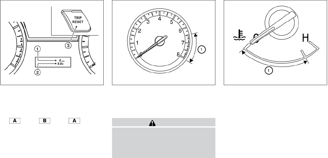
Changing the display:
Pushing the TRIP RESET 䊊
3switch on the right
of the combination meter to change the display
as follows:
Trip →Trip →Trip
Resetting the trip odometer:
Pushing the TRIP RESET switch 䊊
3for more
than 1 second resets the currently displayed trip
odometer to zero.
Average fuel economy and distance to empty
information is also available. See “Vehicle Infor-
mation Display” in this section.
TACHOMETER
The tachometer indicates engine speed in revo-
lutions per minute (rpm). Do not rev the engine
into the red zone 䊊
1.
CAUTION
When engine speed approaches the red
zone, shift to a higher gear or reduce en-
gine speed. Operating the engine in the
red zone may cause serious engine
damage.
ENGINE COOLANT TEMPERATURE
GAUGE
The gauge indicates the engine coolant tempera-
ture. The engine coolant temperature is within the
normal range 䊊
1when the gauge needle points
within the zone shown in the illustration.
The engine coolant temperature varies with the
outside air temperature and driving conditions.
LIC2234 LIC2219 LIC2220
Instruments and controls 2-5

CAUTION
If the gauge indicates coolant tempera-
ture near the hot (H) end of the normal
range, reduce vehicle speed to decrease
temperature. If the gauge is over the nor-
mal range, stop the vehicle as soon as
safely possible. If the engine is over-
heated, continued operation of the vehicle
may seriously damage the engine. See “If
your vehicle overheats” in the “In case of
emergency” section for immediate action
required.
FUEL GAUGE
The gauge indicates the approximate fuel level
in the tank.
The gauge may move slightly during braking,
turning, acceleration, or going up or down hills.
The gauge needle returns to 0 (Empty) after the
ignition switch is placed in the OFF position.
The low fuel warning light comes on when the
amount of fuel in the tank is getting low.
Refill the fuel tank before the gauge regis-
ters 0 (Empty).
The indicates that the fuel-filler door is
located on the driver’s side of the vehicle.
CAUTION
●If the vehicle runs out of fuel, the
Malfunction Indicator Light (MIL) may
come on. Refuel as soon as possible.
After a few driving trips. the light
should turn off. If the light remains on
after a few driving trips, have the vehicle
inspected by a INFINITI retailer.
●For additional information, see “Mal-
function Indicator Light (MIL)” later in
this section.
LIC2222
2-6 Instruments and controls

Anti-lock Braking System (ABS) warning light Seat belt warning light and chime Malfunction indicator light (MIL)
or Brake warning light Supplemental air bag warning light Security indicator light
Charge warning light Fog light indicator light Side light and headlight indicator light (green)
Low tire pressure warning light Front passenger air bag status light Slip indicator light
Master warning light High beam indicator light (blue) Turn signal/hazard indicator lights
Power steering warning light Intelligent Brake Assist (IBA) off indicator light
(if so equipped)
Vehicle Dynamic Control (VDC) off indicator
light
CHECKING BULBS
With all doors closed, apply the parking brake
and place the ignition switch to the ON position
without starting the engine. The following lights
will come on:
, or , ,
The following lights come on briefly and then go
off:
, , , , ,
,
If any light fails to come on, it may indicate
a burned-out bulb or an open circuit in the
electrical system. Have the system repaired
promptly.
WARNING LIGHTS
For additional information on warnings and indi-
cators, see “Vehicle information display” later in
this section.
Anti-lock Braking System
(ABS) warning light
When the ignition switch is placed in the ON
position, the Anti-lock Braking System (ABS)
warning light illuminates and then turns off. This
indicates the ABS is operational.
If the ABS light comes on while the engine is
running, it may indicate the anti-lock braking sys-
tem is not functioning properly. Have the system
checked by an INFINITI retailer.
WARNING/INDICATOR LIGHTS AND
AUDIBLE REMINDERS
Instruments and controls 2-7

If an ABS malfunction occurs, the anti-lock func-
tion is turned off. The brake system then operates
normally, but without anti-lock assistance. See
“Brake system” in the “Starting and driving” sec-
tion.
or Brake warning light
This light functions for both the parking brake and
the foot brake systems.
Parking brake indicator
When the ignition switch is placed in the ON
position, the light comes on when the parking
brake is applied.
Low brake fluid warning light
When the ignition switch is placed in the ON
position, the light warns of a low brake fluid level.
If the light comes on while the engine is running
with the parking brake not applied, stop the ve-
hicle and perform the following:
1. Check the brake fluid level. Add brake fluid
as necessary. See “Brake fluid” in the “Main-
tenance and do-it-yourself” section of this
manual.
2. If the brake fluid level is correct, have the
warning system checked by an INFINITI re-
tailer.
WARNING
●Your brake system may not be working
properly if the warning light is on. Driv-
ing could be dangerous. If you judge it
to be safe, drive carefully to the nearest
service station for repairs. Otherwise,
have your vehicle towed because driv-
ing it could be dangerous.
●Pressing the brake pedal with the en-
gine stopped and/or a low brake fluid
level may increase your stopping dis-
tance and braking will require greater
pedal effort as well as pedal travel.
●If the brake fluid level is below the
MINIMUM or MIN mark on the brake
fluid reservoir, do not drive until the
brake system has been checked at an
INFINITI retailer.
Anti-lock Braking System (ABS) warning
indicator
When the parking brake is released and the
brake fluid level is sufficient, if both the brake
warning light and the Anti-lock Braking System
(ABS) warning light illuminate, it may indicate the
ABS is not functioning properly. Have the brake
system checked, and if necessary, repaired by an
INFINITI retailer promptly. Avoid high-speed driv-
ing and abrupt braking. (See “Anti-lock Braking
System (ABS) warning light” in this section.)
Charge warning light
If this light comes on while the engine is running,
it may indicate the charging system is not func-
tioning properly. Turn the engine off and check
the generator belt. If the belt is loose, broken,
missing, or if the light remains on, see an INFINITI
retailer immediately.
CAUTION
●Do not ground electrical accessories di-
rectly to the battery terminal. Doing so
will bypass the variable control system
and the vehicle battery may not charge
completely. Refer to “Variable voltage
control system” in the “Maintenance
and do-it-yourself” section later in this
manual.
●Do not continue driving if the generator
belt is loose, broken or missing.
Low tire pressure warning light
Your vehicle is equipped with a Tire Pressure
Monitoring System (TPMS) that monitors the tire
pressure of all tires except the spare.
2-8 Instruments and controls

The low tire pressure warning light warns of low
tire pressure or indicates that the TPMS is not
functioning properly.
After the ignition switch is placed in the ON
position, this light illuminates for about 1 second
and turns off.
Low tire pressure warning:
If the vehicle is being driven with low tire
pressure, the warning light will illuminate.
A “Tire Press Low - Add Air” warning also
appears in the vehicle information display.
When the low tire pressure warning light
illuminates, you should stop and adjust the
tire pressure of all 4 tires to the recom-
mended COLD tire pressure shown on the
Tire and Loading Information label located
in the driver’s door opening. The low tire
pressure warning light does not automati-
cally turn off when the tire pressure is ad-
justed. After the tire is inflated to the rec-
ommended pressure, the vehicle must be
driven at speeds above 16 MPH (25 km/h)
to activate the TPMS and turn off the low
tire pressure warning light. Use a tire pres-
sure gauge to check the tire pressure.
The “Tire Press Low - Add Air” warning appears
each time the ignition switch is placed in the ON
position as long as the low tire pressure warning
light remains illuminated.
For additional information, see “Vehicle informa-
tion display” in the “Instruments and controls”
section and “Tire Pressure Monitoring System
(TPMS)” in the “Starting and driving” section and
in the “In case of emergency” section.
TPMS malfunction:
If the TPMS is not functioning properly, the low
tire pressure warning light will flash for approxi-
mately 1 minute when the ignition switch is
placed in the ON position. The light will remain on
after the 1 minute. Have the system checked by
an INFINITI retailer. The “Tire Pressure Low - Add
Air” warning does not appear if the low tire pres-
sure warning light illuminates to indicate a TPMS
malfunction.
For additional information, see “Tire Pressure
Monitoring System (TPMS)” in the “Starting and
driving” section and “Tire pressure” in the “Main-
tenance and do-it-yourself” section.
WARNING
●Radio waves could adversely affect
electric medical equipment. Those who
use a pacemaker should contact the
electric medical equipment manufac-
turer for the possible influences before
use.
●If the light does not illuminate with the
ignition switch placed in the ON posi-
tion, have the vehicle checked by an
INFINITI retailer as soon as possible.
Instruments and controls 2-9

●
If the light illuminates while driving,
avoid sudden steering maneuvers or
abrupt braking, reduce vehicle speed,
pull off the road to a safe location and
stop the vehicle as soon as possible.
Driving with under-inflated tires may per-
manently damage the tires and increase
the likelihood of tire failure. Serious ve-
hicle damage could occur and may lead
to an accident and could result in serious
personal injury. Check the tire pressure
for all four tires. Adjust the tire pressure
to the recommended COLD tire pressure
shown on the Tire and Loading Informa-
tion label located in the driver’s door
opening to turn the low tire pressure
warning light OFF. If the light still illumi-
nates while driving after adjusting the
tire pressure, a tire may be flat. If you
have a flat tire, replace it with a spare tire
as soon as possible.
●When a spare tire is mounted or a wheel
is replaced tire pressure will not be in-
dicated, the TPMS will not function and
the low tire pressure warning light will
flash for approximately 1 minute. The
light will remain on after 1 minute. Con-
tact your INFINITI retailer as soon as
possible for tire replacement and/or
system resetting.
●Replacing tires with those not originally
specified by INFINITI could affect the
proper operation of the TPMS.
CAUTION
●The TPMS is not a substitute for the
regular tire pressure check. Be sure to
check the tire pressure regularly.
●If the vehicle is being driven at speeds
of less than 16 MPH (25 km/h), the
TPMS may not operate correctly.
●Be sure to install the specified size of
tires to the 4 wheels correctly.
Master warning light
When the ignition switch is in the ON position, the
master warning light illuminates if any of the follow-
ing are displayed on the vehicle information display:
●No key warning
●Low fuel warning
●Low washer fluid warning
●Parking brake release warning
●Door open warning
●Loose fuel cap warning (if so equipped)
●Check tire pressure warning (if so equipped)
See “Vehicle Information Display” later in this
section.
Power steering warning light
WARNING
●If the engine is not running or is turned
off while driving, the power assist for
the steering will not work. Steering will
be harder to operate.
●When the power steering warning light
illuminates with the engine running,
there will be no power assist for the
steering. You will still have control of
the vehicle but the steering will be
harder to operate. Have the power
steering system checked by an INFINITI
retailer.
When the ignition switch is placed in the ON
position, the power steering warning light illumi-
nates. After starting the engine, the power steer-
ing warning light turns off. This indicates that the
electric power steering system is operational.
If the power steering warning light illuminates
while the engine is running, it may indicate the
power steering system is not functioning properly
and may need servicing. Have the hydraulic pump
electric power steering system checked by an
INFINITI retailer.
2-10 Instruments and controls
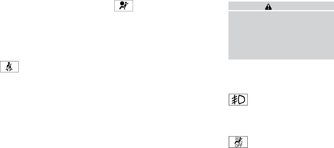
When the power steering warning light illumi-
nates with the engine running, there will be no
power assist for the steering but you will still have
control of the vehicle. At this time, greater steer-
ing effort is required to operate the steering
wheel, especially in sharp turns and at low
speeds.
See “Power steering” in the “Starting and driving”
section.
Seat belt warning light and
chime
The light and chime remind you to fasten your
seat belts. The light illuminates whenever the
ignition switch is placed in the ON or START
position and remains illuminated until the driver’s
seat belt is fastened. At the same time, the chime
sounds for about 6 seconds unless the driver’s
seat belt is securely fastened.
The seat belt warning light may also illuminate if
the front passenger’s seat belt is not fastened
when the front passenger’s seat is occupied . For
7 seconds after the ignition switch is placed in
the ON position, the system does not activate the
warning light for the front passenger.
Refer to “Seat belts” in the “Safety—Seats, seat
belts and supplemental restraint system” section
for precautions on seat belt usage.
Supplemental air bag warning
light
When the ignition switch is placed in the ON
position, the supplemental air bag warning light
illuminates for about 7 seconds and then turns
off. This means the system is operational.
If any of the following conditions occur, the front
air bag, front seat-mounted side-impact air bag,
roof-mounted curtain air bag and pretensioner
systems need servicing and your vehicle must be
taken to an INFINITI retailer:
●The supplemental air bag warning light re-
mains on after approximately 7 seconds.
●The supplemental air bag warning light
flashes intermittently.
●The supplemental air bag warning light does
not come on at all.
Unless checked and repaired, the supplemental
restraint system (air bag system) and/or the pre-
tensioner systems may not function properly. For
additional details see “Supplemental restraint
system” in the “Safety—Seats, seat belts and
supplemental restraint system” section of this
manual.
WARNING
If the supplemental air bag warning light
is on, it could mean that the front air bag,
side air bag, curtain air bag systems
and/or pretensioner systems will not op-
erate in an accident. To help avoid injury to
yourself or others, have your vehicle
checked by an INFINITI retailer as soon as
possible.
INDICATOR LIGHTS
For additional information on warnings and indi-
cators, see “Vehicle information display” later in
this section.
Fog light indicator light
The front fog light indicator light illuminates when
the front fog lights are ON when the headlights
are ON. See “Fog light switch” later in this sec-
tion.
Front passenger air bag status
light
The front passenger air bag status light will be lit
and the passenger front air bag will be OFF
depending on how the front passenger seat is
being used.
Instruments and controls 2-11

For front passenger air bag status light operation,
see “Front passenger air bag and status light” in
the “Safety — Seats, seat belts and supplemental
restraint system” section of this manual.
High beam indicator light
(blue)
This blue light comes on when the headlight high
beams are on and goes out when the low beams
are selected.
The high beam indicator light also comes on
when the passing signal is activated.
Intelligent Brake Assist (IBA)
off indicator light (if so
equipped)
The light illuminates when the Warning System
Switch is off and the Intelligent Brake Assist is
disabled in the Vehicle information display. This
indicates that the Intelligent Brake Assist (IBA)
system is not operating.
When the IBA off indicator light illuminates while
the system is enabled this indicates that the
system control is temporarily disabled.
If the IBA off indicator light illuminates when the
system is enabled and the warning system switch
is on, have the system checked at an INFINITI
retailer.
Malfunction Indicator Light
(MIL)
If this indicator light comes on steady or blinks
while the engine is running, it may indicate a
potential emission control malfunction.
The Malfunction Indicator Light may also come
on steady if the fuel-filler cap is loose or missing,
or if the vehicle runs out of fuel. Check to make
sure the fuel-filler cap is installed and closed
tightly, and that the vehicle has at least 3 gallons
(11.4 liters) of fuel in the fuel tank.
After a few driving trips, the light should
turn off if no other potential emission control
system malfunction exists.
If this indicator light comes on steady for 20 sec-
onds and then blinks for 10 seconds when the
engine is not running, it indicates that the vehicle
is not ready for an emission control system
inspection/maintenance test. See “Readiness for
inspection/maintenance (I/M) test” in the “Tech-
nical and consumer information” section of this
manual.
Operation
The Malfunction Indicator Light will come on in
one of two ways:
●Malfunction Indicator Light on steady — An
emission control system malfunction has
been detected. Check the fuel-filler cap if
the LOOSE FUEL CAP warning appears in
the vehicle information display. If the fuel-
filler cap is loose or missing, tighten or install
the cap and continue to drive the vehicle.
The light should turn off after a few
driving trips. If the light does not turn
off after a few driving trips, have the vehicle
inspected by an INFINITI retailer. You do not
need to have your vehicle towed to an
INFINITI retailer.
●Malfunction Indicator Light blinking — An
engine misfire has been detected which may
damage the emission control system. To re-
duce or avoid emission control system dam-
age:
– do not drive at speeds above 45 MPH
(72 km/h).
– avoid hard acceleration or deceleration.
– avoid steep uphill grades.
– if possible, reduce the amount of cargo
being hauled or towed.
2-12 Instruments and controls

The Malfunction Indicator Light may stop blinking
and come on steady. Have the vehicle inspected
by an INFINITI retailer. You do not need to have
your vehicle towed to an INFINITI retailer.
CAUTION
Continued vehicle operation without hav-
ing the emission control system checked
and repaired as necessary could lead to
poor driveability, reduced fuel economy,
and possible damage to the emission con-
trol system.
Security indicator light
This light blinks whenever the ignition switch is in
the LOCK, OFF or ACC position. This function
indicates the security system equipped on the
vehicle is operational.
For additional information, see “Security sys-
tems” later in this section.
Side light and headlight
indicator light (green)
The side light and headlight indicator light illumi-
nates when the side light or headlight position is
selected. See “Headlight and turn signal switch”
later in this section for further details.
Slip indicator light
This indicator will blink when the VDC system or
the traction control system is operating, thus
alerting that the vehicle is nearing its traction
limits. The road surface may be slippery.
Turn signal/hazard indicator
lights
The appropriate light flashes when the turn signal
switch is activated.
Both lights flash when the hazard switch is turned
on.
Vehicle Dynamic Control
(VDC) off indicator light
This indicator light comes on when the Vehicle
Dynamic Control off switch is pushed to OFF.
This indicates the Vehicle Dynamic Control has
been turned off.
Push the Vehicle Dynamic Control off switch
again or restart the engine and the system will be
reactivated. See “Vehicle Dynamic Control
(VDC) system” in the “Starting and driving” sec-
tion of this manual.
The Vehicle Dynamic Control light also comes on
when the ignition switch is placed to the ON
position. The light will turn off after about 2 sec-
onds if the system is operational. If the light stays
on or comes on along with the indicator
light while you are driving, have the Vehicle Dy-
namic Control system checked by an INFINITI
retailer.
WARNING
VDC should remain on unless freeing a
vehicle from mud or snow.
While the Vehicle Dynamic Control system is
operating, you might feel slight vibration or hear
the system working when starting the vehicle or
accelerating, but this is normal.
AUDIBLE REMINDERS
Brake pad wear warning
The disc brake pads have audible wear warnings.
When a disc brake pad requires replacement, it
makes a high pitched scraping sound when the
vehicle is in motion, whether or not the brake
pedal is depressed. Have the brakes checked as
soon as possible if the warning sound is heard.
Key reminder chime
A chime sounds if the driver’s door is opened
while the ignition switch is placed in the ACC or
OFF position or placed in the OFF or LOCK
position with the Intelligent Key left in the vehicle.
Instruments and controls 2-13

Make sure the ignition switch is placed in the
LOCK position, and take the Intelligent Key with
you when leaving the vehicle.
Lane departure warning chime (if so
equipped)
When the Lane Departure Warning (LDW) or
Lane Departure Prevention (LDP) system is on,
the chime sounds if the vehicle is traveling close
to either the left or the right of a traveling lane with
detectable lane markers.
See “Lane Departure Warning (LDW)
system/Lane Departure Prevention (LDP) sys-
tem” in the “Starting and driving” section for more
details.
Light reminder chime
With the ignition switch placed in the OFF posi-
tion, a chime sounds when the driver’s door is
opened if the headlights or parking lights are on.
Turn the headlight control switch off before leav-
ing the vehicle.
Intelligent Key door buzzer
The Intelligent Key door buzzer sounds if any one
of the following improper operations is found.
●The ignition switch is not returned to the
LOCK position when locking the doors.
●The Intelligent Key is left inside the vehicle
when locking the doors.
●The Intelligent Key is taken outside the ve-
hicle when operating the vehicle.
●Any doors are not closed securely when
locking the doors.
When the buzzer sounds, be sure to check both
the vehicle and the Intelligent Key System. See
“INFINITI Intelligent Key” in the “Pre-driving
checks and adjustments” section.
The vehicle information display is located to the
left of the speedometer. It displays such items as:
●Vehicle settings
●Trip computer information
●Drive system warnings and settings (if so
equipped)
●Cruise control system (if so equipped)/
Intelligent Cruise Control (ICC) system (if so
equipped) information
●Intelligent Key operation information
●Indicators and warnings
●Tire Pressure information
●other information
LIC2205
VEHICLE INFORMATION DISPLAY
2-14 Instruments and controls

HOW TO USE THE VEHICLE
INFORMATION DISPLAY
The vehicle information display can be changed
using the buttons and ENTER located on
the steering wheel.
1. — to enter the Vehicle information
menu items
2. — to navigate through the items in
vehicle information
ENTER — to change or select an item in the
vehicle information display
3. — to go back to the previous menu
The ENTER, and buttons also controls au-
dio and INFINITI controller functions. For addi-
tional information see, “Steering wheel switch for
audio control” in “Monitor, climate, audio, phone
and voice recognition systems” section.
STARTUP DISPLAY
When the vehicle in placed in the ON or ACC
position the screens that display in the vehicle
information include:
●Active system status (if so equipped)
●Trip computer
●Tire pressure information
●Fuel economy
●Warnings
Warnings will only display if there are any pres-
ent, for more information on warnings and indica-
tors see, “Vehicle information display warnings
and indicators” in this section.
To control what items display in the vehicle infor-
mation display, see “Main menu selection” in this
section.
SETTINGS
The setting mode allows you to change the infor-
mation displayed in the vehicle information display:
●Driver Assistance (if so equipped)
●Vehicle Settings
●Main Menu Selection
●Body Color
●Maintenance
●Alarms
●Language
●Unit
●Welcome Effects
Driver Assistance (if so equipped)
To change the status, warnings or turn on or off
any of the systems/warnings displayed in the
“Driver Assistance” menu:
Use the button to select and the ENTER
button to change a menu item:
●Driving Aids (if so equipped)
●Back-up Collision Inter. (if so equipped)
●Intelligent Brake Assist (if so equipped)
LIC2245
Instruments and controls 2-15

Driving Aids (if so equipped)
To change the status, warnings or turn on or off
any of the systems/warnings displayed in the
“Driving Aids” menu.
Use the button to select and the ENTER
button to change a menu item:
●Forward
●Warning (FCW)
●Assistance (DCA)
●Lane
●Warning (LDW)
●Assistance (LDP)
●Blind Spot
●Warning (BSW)
●Assistance (BSI)
●Brightness — Bright/STD/Dark
Back-up Collision Interv.(ention) (if so
equipped)
The back-up collision intervention system can be
changed to be ON when the ignition switch is
placed in the ON position and to Auto Resume.
Use the button to select and the ENTER
button to change a menu item:
●Ignition On Status – On/Off
Intelligent Brake Assist (if so equipped)
The intelligent brake assist system can be
enabled/disabled in the vehicle information dis-
play.
Use the button to select and the ENTER
button to change a menu item:
●System – On/Off
Vehicle Settings
The vehicle settings allows the customer to
change settings for rain sensor (if so equipped),
interior lights, intelligent key settings, unlock set-
tings and other vehicle settings.
The vehicle settings can be changed using
the , , and the ENTER buttons.
Welcome light (if so equipped)
The welcome light can be set to be ON or OFF.
From the Vehicle Settings menu, select “Wel-
come Light”. Use the ENTER button to turn this
feature ON or OFF.
Auto Room Lamp
The interior lights can be set to be ON or OFF if
any door is unlocked. From the Vehicle Settings
menu, select “Auto Room Light”. Use the ENTER
button to turn this feature ON or OFF.
Light Sensitivity
The lights sensitivity can be set to the illuminate
earlier based on the brightness outside the ve-
hicle. From the Vehicle Settings menu, select
“Light Sensitivity”. Use the ENTER button to
change the sensitivity.
Light Off Delay
The duration of the automatic headlights can be
changed from 0 to 180 seconds. From the Ve-
hicle Settings menu, select “Light Off Delay”. Use
the ENTER button to change the duration.
Rain Sensor (if so equipped)
The rain sensor can be set to be ON or OFF. From
the Vehicle Settings menu, select “Rain Sensor”.
Use the ENTER button to turn this feature ON or
OFF.
Wiper with Speed
The wiper with speed can be set to be ON or
OFF. From the Vehicle Settings menu, select
“Wiper with Speed”. Use the ENTER button to
turn this feature ON or OFF.
2-16 Instruments and controls

I-Key Door Lock
When this item is turned on, the request switch
on the door is activated. From the Vehicle Set-
tings menu, select “I-Key Door Unlock”. Use the
ENTER button to activate this function.
Selective-Unlock
When this item is turned on, only the driver’s door
is unlocked first after the door unlock operation.
When the door handle request switch on the
driver’s or front passenger’s side door is pushed
to be unlocked, only the corresponding door is
unlocked first. All the doors can be unlocked if the
door unlock operation is performed again within
1 minute. When this item is turned to off, all the
doors will be unlocked after the door unlock
operation is performed once. From the Vehicle
Settings menu, select “Selective Unlock”. Use
the ENTER button to activate this function.
Auto Door Unlock
The auto door unlock function automatically un-
locks all the doors when the shift lever is placed in
the P (Park) position. From the Vehicle Settings
menu, select “Auto Door Unlock”. Use the EN-
TER button to enable/disable this function.
Answer back horn
When the answer back horn is on the horn will
chirp and the hazard indicators will flash once
when locking the vehicle with the Intelligent Key.
Remote Start (if so equipped)
The remote start function can be turned on or off.
If the setting is OFF the vehicle cannot be started
using the intelligent key. From the Vehicle Set-
tings menu, select “Remote Start”. Use the EN-
TER button to enable/disable.
Battery Saver
The battery saver automatically turns off the igni-
tion after a period of time when the ignition switch
is left in the ACC or ON position.
Exit Seat Slide (if so equipped)
When the Exit seat slide is ON the driver’s seat
will move backward for easy exit when the ignition
switch is placed in the OFF position and the
driver’s door is opened.
After getting into the vehicle and placing the
ignition switch in the ACC position, the driver’s
seat will move to the previous set position. For
more information for setting the seat position see
“Automatic drive positioner” in the “Pre-driving
checks and adjustments” section. Use the EN-
TER button to enable/disable this function.
Exit steering up (if so equipped)
When the exit steering up is turned ON, the
steering wheel moving upward for easy exit when
the ignition switch is in the OFF position and the
driver’s door is opened.
After getting into the vehicle and placing the
ignition switch in the ACC position, the steering
wheel moves to the previous position. For more
information for setting the steering wheel posi-
tion, see “Tilt and telescopic operation” in the
“Pre-driving checks and adjustments” section.
Use the ENTER button to enable/disable this
function.
Main Menu Selection
The items that display can be turned
enabled/disabled when the ignition switch is
placed in the ON position. To change the items
that display.
Use the button to select and the ENTER
button to change a menu item.
●Driver assistance (if so equipped)
●Trip computer
●Fuel economy
●Tire pressures
Instruments and controls 2-17

Driver Assistance (if so equipped)
The driver assistance system can
enabled/disabled to display in the vehicle infor-
mation display when the ignition switch is placed
in the ON position
From the “Main Menu Selection” select “Driver
Assistance” to display in the vehicle information
display when the ignition is placed in the ON
position.
Trip Computer
The trip computer can be enabled/disabled to
display in the vehicle information display when
the ignition switch is placed in the ON position.
From the “Main Menu Selection” select “Trip
Computer” to display in the vehicle information
display when the ignition is placed in the ON
position.
Tire Pressures
The tire pressures can be enabled/disabled to
display in the vehicle information display when
the ignition switch is placed in the ON position.
From the “Main Menu Selection” select “Tire
Pressures” to display in the vehicle information
display when the ignition is placed in the ON
position.
Fuel Economy
The fuel economy can be enabled/disabled to
display in the vehicle information display when
the ignition switch is placed in the ON position.
From the “Main Menu Selection” select “Fuel
Economy” to display in the vehicle information
display when the ignition is placed in the ON
position.
Body Color
The color of the vehicle that displays in the ve-
hicle information display when the ignition switch
is placed in the ON position can be changed.
Maintenance
The maintenance mode allows you to set alerts
for the reminding of maintenance intervals for the
following:
●scheduled service
●tires
●other
1. Press the button.
2. Using the button until “Settings” is
selected, and press ENTER.
3. Select “Maintenance” using the but-
tons and press ENTER.
Service
This indicator appears when the customer set
distance comes for checking or replacing main-
tenance items other than the engine oil, oil filter
and tires. Other maintenance items can include
such things as air filter or tire rotation. You can set
or reset the distance for checking or replacing
the items. You can set or reset the distance for
service type items. For scheduled maintenance
items and intervals, see your “INFINITI Service
and Maintenance Guide.”
Tire
This indicator appears when the customer set
distance comes for replacing tires. You can set or
reset the distance for replacing tires.
2-18 Instruments and controls

WARNING
The tire replacement indicator is not a
substitute for regular tire checks, includ-
ing tire pressure checks. See “Changing
Wheels and Tires” in “Maintenance & Do-
It-Yourself” section. Many factors includ-
ing tire inflation, alignment, driving habits
and road conditions affect tire wear and
when tires should be replaced. Setting the
tire replacement indicator for a certain
driving distance does not mean your tires
will last that long. Use the tire replace-
ment indicator as a guide only and always
perform regular tire checks. Failure to per-
form regular tire checks, including tire
pressure checks could result in tire failure.
Serious vehicle damage could occur and
may lead to a collision, which could result
in serious personal injury or death.
Other
This indicator appears when the customer set
distance comes for checking or replacing main-
tenance items other than the engine oil, oil filter
and tires. Other maintenance items can include
such things as air filter or tire rotation. You can set
or reset the distance for checking or replacing
the items.
Alarms
This setting allows the customer to set alarms for
outside temperature and a timer alert.
1. Press the button.
2. Use the button until “Settings” is se-
lected, and press ENTER.
3. Select “Alarms”using the buttons and
press ENTER.
Outside Temperature
This setting allows the customer to
enable/disable the alert for low outside tempera-
ture in the vehicle information display.
1. Use the buttons to select “Outside
Temperature”.
2. Press the ENTER button to turn ON/OFF
the outside temperature in the vehicle infor-
mation display.
Timer Alert
This setting allows the customer to set an alert to
notify the driver that the set time has been
reached.
1. Use the buttons to select “Timer
Alert”.
2. Press the ENTER button.
3. To change the timer amount, use the
buttons and the ENTER button to save the
selected time amount.
Language
The language of the vehicle information display
can be changed to:
●US English
●French
●Spanish
Use the , , and the ENTER buttons to
select and change the language of the vehicle
information display. The language of the center
display/navigation can be changed indepen-
dently of the vehicle information display. For ve-
hicles not equipped with Navigation see “Lan-
guage / Units” and vehicles equipped with
Navigation see, “Others settings” in the “Monitor,
climate, audio, phone and voice recognition sys-
tems” section of this manual.
Units
The units that are shown in the vehicle informa-
tion display can be changed:
●Mileage
●Tire pressures
●Temperature
Instruments and controls 2-19

Use the , , and the ENTER buttons to
select and change the units of the vehicle infor-
mation display. The units of the center
display/navigation can be changed indepen-
dently of the vehicle information display. For ve-
hicles not equipped with Navigation see “Lan-
guage / Units” and vehicles equipped with
Navigation see, “Others settings” and for in the
“Monitor, climate, audio, phone and voice recog-
nition systems” section of this manual.
Mileage
The unit for the mileage that displays in the ve-
hicle information display can be changed to:
●miles, MPG, Inch
●km/h, l/100km, cm
●km/h, km/l, cm
Use the and the ENTER buttons to select
and change the unit.
Tire Pressures
The unit for tire pressure that displays in the
vehicle information display can be changed to:
●psi
●kPa
●bar
●Kgf/cm
2
Use the and the ENTER buttons to select
and change the unit.
Temperature
The temperature that displays in the vehicle infor-
mation display can be changed from:
●°F (Fahrenheit)
●°C (Celsius)
Use the ENTER button to toggle choices.
Welcome Effects
The welcome screen display can be turned
ON/OFF to display when the ignition switch is
placed in the ACC or ON position. To
enable/disable the welcome screen:
1. Press the button.
2. Use the buttons to select “Settings”,
and press ENTER.
3. Select “Welcome Effects” using the
buttons and press ENTER to turn this func-
tion ON or OFF.
Factory Reset
The settings in the vehicle information display can
be reset back to the factory default. To reset the
vehicle information display:
1. Press the button.
2. Use the buttons to select “Settings”,
and press the ENTER button.
3. Select “Factory Reset” using the but-
tons and press the ENTER button.
4. Select “YES” to return all settings back to
default by pressing the ENTER button.
2-20 Instruments and controls

VEHICLE INFORMATION DISPLAY
WARNINGS AND INDICATORS
1. No Key Detected
2. Key ID Incorrect
3. Shift to Park
4. Push ignition to OFF
5. Key Battery Low
6.
Engine start operation for Intelligent Key system
7. Release Parking brake
8. Low Fuel
9. Low Washer Fluid
10. Door Open
11. Liftgate Open
12. Timer Alert – Time for a driver break?
LIC2559
Instruments and controls 2-21
13. Low Outside Temperature
14. Power will turn off to save the battery
15. CVT Error
16. Reminder: Turn OFF headlights
17. Low Oil Pressure
18. Key Registration Complete
19. Tire Pressure Low - Add Air
20. TPMS Error
21. Parking Sensor Error
22. Remote Start (if so equipped)
23. Loose Fuel Cap
24. I-Key System Error: See Owners Manual
No Key Detected
This warning appears when the intelligent key is
left outside the vehicle with the ignition switch is
the ON or ACC position. Make sure the Intelli-
gent Key is inside the vehicle.
Key ID Incorrect
The warning appears when the ignition switch is
placed from the OFF position and the intelligent
key is not recognized by the system. You can not
start the engine with an unregistered key.
See “INFINITI Intelligent Key System” in “Pre-
driving checks and adjustments” for more infor-
mation.
Shift to Park
This warning illuminates when the ignition switch
is in the ACC or OFF position and the shift lever
is in any position other than P (Park) position.
Also, a chime sounds when the ignition switch is
in the OFF position.
If this warning illuminates, move the shift lever to
the P (Park) position or start the engine.
For additional information about Intelligent Key,
see “INFINITI Intelligent Key” in the “Pre-driving
checks and adjustments” section.
Push ignition to OFF
After the Push ignition to OFF warning illumi-
nates, the warning will illuminate if the ignition
switch is placed in the ACC position when the
shift lever is moved to the P (Park) position.
To turn off the Push warning, place the ignition
switch in the ON position and then in the LOCK
position.
Key Battery Low
This indicator illuminates when the Intelligent Key
battery is running out of power.
If this indicator illuminates, replace the battery
with a new one. See “Battery replacement” in the
“Maintenance and do-it-yourself” section.
Engine start operation for Intelligent Key
system
This indicator appears when the battery of the
Intelligent Key is low and when the Intelligent Key
system and the vehicle are not communicating
normally.
If this appears, touch the ignition switch with the
Intelligent Key while depressing the brake pedal.
For more information see, “INFINITI Intelligent
Key battery discharge” in the “Starting and driv-
ing” section.
Release Parking brake
This warning illuminates in the message area of
the vehicle information display when the parking
brake is set and the vehicle is driven.
Low Fuel
This warning illuminates when the fuel level in the
fuel tank is getting low. Refuel as soon as it is
convenient, preferably before the fuel gauge
reaches 0 (Empty). There will be a small re-
serve of fuel in the tank when the fuel
gauge needle reaches 0 (Empty).
2-22 Instruments and controls

Push to start (if so equipped)
This warning appears in the vehicle information
display when the vehicle has been started using
the remote start function. To start the vehicle,
apply the brake and place the ignition switch in
the ON position.
Loose Fuel Cap
This warning appears when the fuel-filler cap is
not tightened correctly after the vehicle has been
refueled. See “Fuel-filler cap” in the “Pre-driving
checks and adjustments” section of this manual.
Intelligent Key error
After the ignition switch is pushed to the ON
position, this light comes on for about 2 seconds
and then turns off.
The I-Key System Error message warns of a
malfunction with the Intelligent Key system. If the
light comes on while the engine is stopped, it may
be impossible to start the engine.
If the light comes on while the engine is running,
you can drive the vehicle. However in these
cases, contact an INFINITI retailer for repair as
soon as possible.
Your vehicle has two types of security systems:
●Vehicle security system
●INFINITI Vehicle Immobilizer System
VEHICLE SECURITY SYSTEM
The vehicle security system provides visual and
audible alarm signals if someone opens the
doors, liftgate or hood when the system is armed.
It is not, however, a motion detection type system
that activates when a vehicle is moved or when a
vibration occurs.
The system helps deter vehicle theft but cannot
prevent it, nor can it prevent the theft of interior or
exterior vehicle components in all situations. Al-
ways secure your vehicle even if parking for a
brief period. Never leave your Intelligent Key in
the vehicle, and always lock the vehicle when
unattended. Be aware of your surroundings, and
park in secure, well-lit areas whenever possible.
Many devices offering additional protection, such
as component locks, identification markers, and
tracking systems, are available at auto supply
stores and specialty shops. Your INFINITI retailer
may also offer such equipment. Check with your
insurance company to see if you may be eligible
for discounts for various theft protection features.
How to arm the vehicle security
system
1. Close all windows and the moonroof. The
system can be armed even if the win-
dows and moonroof are open.
2. Remove the Intelligent Key from the vehicle.
3. Close all doors, hood and liftgate. Lock all
doors. The doors can be locked with the
Intelligent Key, door handle request switch
or power door lock switch.
Keyfob operation:
4. Confirm that the indicator light comes
on. The indicator stays illuminated for
a period of time indicating that the system is
in the pre-armed phase.
LIC2226
SECURITY SYSTEMS
2-24 Instruments and controls

The indicator light will blink every
three seconds once the security system is
armed.
If during the pre-armed phase one of the
following occurs, the system will not arm:
●Any door is unlocked with the mechanical
key
●A door is opened with the release button
with the intelligent key on your person
●The doors are unlocked using the unlock
button on the intelligent key
●The ignition switch is placed in the ACC
or ON position
●Even when the driver and/or passen-
gers are in the vehicle, the system will
activate with all the doors, hood and
liftgate are locked with the ignition
switch placed in the LOCK position.
When placing the ignition switch in the
ACC or ON position, the system will be
released.
Vehicle security system activation
The vehicle security system will give the following
alarm:
●The turn signals blink and the horn sounds
intermittently.
●The alarm automatically turns off after a pe-
riod of time. However, the alarm reactivates if
the vehicle is tampered with again. The alarm
can be shut off by unlocking the driver’s door
or liftgate with the key, or by pressing
the button on the Intelligent Key.
The alarm is activated by:
●opening the door or liftgate without using the
key or Intelligent Key (even if the door is
unlocked by releasing the door inside lock
switch).
How to stop an activated alarm
The alarm stops only by unlocking the driver’s
door or the liftgate with the key, pressing
the button on the Intelligent Key, or press-
ing the request switch on the driver’s or passen-
ger’s door with the Intelligent Key in range of the
door handle.
INFINITI VEHICLE IMMOBILIZER
SYSTEM
The INFINITI Vehicle Immobilizer System will not
allow the engine to start without the use of a
registered INFINITI Vehicle Immobilizer System
key.
If the engine fails to start using a registered
INFINITI Vehicle Immobilizer System key (for ex-
ample, when interference is caused by another
INFINITI Vehicle Immobilizer System key, an au-
tomated toll road device or automatic payment
device on the key ring), restart the engine using
the following procedures:
1. Leave the ignition switch in the ON position
for approximately 5 seconds.
2. Place the ignition switch in the OFF or
LOCK position, and wait approximately
10 seconds.
3. Repeat steps 1 and 2.
4. Restart the engine while holding the device
(which may have caused the interference)
separate from the registered INFINITI Ve-
hicle Immobilizer System key.
If the no start condition re-occurs, INFINITI rec-
ommends placing the registered INFINITI Vehicle
Immobilizer System key on a separate key ring to
avoid interference from other devices.
Instruments and controls 2-25

FCC Notice:
For USA:
This device complies with part 15 of the
FCC Rules. Operation is subject to the fol-
lowing two conditions: (1) This device may
not cause harmful interference, and (2) this
device must accept any interference re-
ceived, including interference that may
cause undesired operation.
NOTE:
Changes or modifications not expressly ap-
proved by the party responsible for compli-
ance could void the user’s authority to op-
erate the equipment.
For Canada:
This device complies with RSS-210 of In-
dustry Canada. Operation is subject to the
following two conditions: (1) This device
may not cause harmful interference, and (2)
this device must accept any interference
received, including interference that may
cause undesired operation of the device.
Security indicator light
The security indicator light blinks whenever the
ignition switch is in the LOCK, OFF or ACC
position. This function indicates the INFINITI Ve-
hicle Immobilizer System is operational.
If the INFINITI Vehicle Immobilizer System is mal-
functioning, the light will remain on while the
ignition switch is in the ON position.
If the light still remains on and/or the en-
gine will not start, see an INFINITI retailer
for service as soon as possible. Please
bring all INFINITI Vehicle Immobilizer Sys-
tem keys that you have when visiting your
INFINITI retailer for service.
WARNING
In freezing temperatures the washer solu-
tion may freeze on the window and ob-
scure your vision which may lead to an
accident. Warm the window with the de-
froster before you wash the window.
CAUTION
●Do not operate the washer continuously
for more than 30 seconds.
●Do not operate the washer if the reser-
voir tank is empty.
●Do not fill the window washer reservoir
with washer fluid concentrates at full
strength. Some methyl alcohol based
washer fluid concentrates may perma-
nently stain the grille if spilled while
filling the window washer reservoir.
●Pre-mix washer fluid concentrates with
water to the manufacturer’s recom-
mended levels before pouring the fluid
into the window washer reservoir. Do
not use the window washer reservoir to
mix the washer fluid concentrate and
water.
LIC0474
WINDSHIELD WIPER AND WASHER
SWITCH
2-26 Instruments and controls
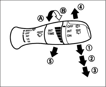
If the windshield wiper operation is interrupted by
snow or ice, the wiper may stop moving to protect
its motor. If this occurs, turn the wiper switch to
the OFF position and remove the snow or ice that
is on and around the wiper arms. In approximately
1 minute, turn the switch on again to operate the
wiper.
SWITCH OPERATION
The windshield wiper and washer operates when
the ignition switch is in the ON position.
Push the lever down to operate the wiper at the
following speed:
䊊
1Intermittent (INT) — intermittent operation
can be adjusted by turning the knob toward
䊊
A(Slower) or 䊊
B(Faster). Also, the inter-
mittent operation speed varies in accor-
dance with the vehicle speed. (For example,
when the vehicle speed is high, the intermit-
tent operation speed will be faster.)
NOTE:
You can turn on or turn off the driving
speed dependent intermittent wiper func-
tion. Refer to “Vehicle information display”
in this section.
For models with the rain-sensing auto wiper sys-
tem, see “Rain-sensing auto wiper system” in this
section.
䊊
2Low (LO) — continuous low speed operation
䊊
3High (HI) — continuous high speed opera-
tion
Push the lever up 䊊
4to have one sweep opera-
tion (MIST) of the wiper.
Pull the lever toward you 䊊
5to operate the
washer. The wiper will also operate several times.
SIC3626
Instruments and controls 2-27

RAIN-SENSING AUTO WIPER
SYSTEM (if so equipped)
The rain-sensing auto wiper system can auto-
matically turn on the wipers and adjust the wiper
speed depending on the rainfall and the vehicle
speed by using the rain sensor located on the
upper part of the windshield.
To set the rain-sensing auto wiper system, push
the lever down to the AUTO position 䊊
1. The
wiper will sweep once while the ignition switch is
in the ON position.
The rain sensor sensitivity level can be adjusted
by turning the knob toward the front 䊊
2(High) or
toward the rear 䊊
3(Low).
– High — High sensitive operation
– Low — Low sensitive operation To turn the
rain-sensing auto wiper system off, push up
the lever to the OFF position, or pull down the
lever to the LO or HI position.
CAUTION
●Do not touch the rain sensor and
around it when the wiper switch is in the
AUTO position and the ignition switch is
in the ON position. The wipers may op-
erate unexpectedly and cause to an in-
jury or a wiper damage.
●The rain-sensing auto wipers are in-
tended for use during rain. If the switch
is left in the AUTO position, the wipers
may operate unexpectedly when dirt,
fingerprints, oil film or insects are stuck
on or around the sensor. The wipers
may also operate when exhaust gas or
moisture affect the rain sensor.
●When the windshield glass is coated
with water repellent, the speed of the
rain-sensing auto wipers may be higher
even though the amount of the rainfall
is small. Be sure to turn off the rain-
sensing auto wiper system when you
use a car wash.
●The rain-sensing auto wipers may not
operate if rain does not hit the rain
sensor even if it is raining.
●Using genuine wiper blades is recom-
mended for proper operation of the
rain-sensing auto wiper system. See
“Windshield wiper blades” in “Mainte-
nance and do-it-yourself” for wiper
blade replacement.
SIC4258
2-28 Instruments and controls

WARNING
In freezing temperatures the washer solu-
tion may freeze on the window and ob-
scure your vision. Warm the rear window
with the defroster before you wash the
rear window.
CAUTION
●Do not operate the washer continuously
for more than 30 seconds.
●Do not operate the washer if the reser-
voir is empty.
●Do not fill the windshield-washer fluid
reservoir with washer fluid concen-
trates at full strength. Some methyl al-
cohol based washer fluid concentrates
may permanently stain the grille if
spilled while filling the windshield-
washer fluid reservoir.
●Pre-mix washer fluid concentrates with
water to the manufacturer’s recom-
mended levels before pouring the fluid
into the windshield-washer fluid reser-
voir. Do not use the windshield-washer
fluid reservoir to mix the washer fluid
concentrate and water.
If the rear window wiper operation is interrupted
by snow etc., the wiper may stop moving to
protect its motor. If this occurs, turn the wiper
switch to OFF and remove the snow etc. on and
around the wiper arms. After about 1 minute, turn
the switch ON again to operate the wiper.
The rear window wiper and washer operate when
the ignition switch is in the ON position. Turn the
switch clockwise from the OFF position to oper-
ate the wiper.
䊊
1Intermittent (INT) — intermittent operation
(not adjustable)
䊊
2Low (ON) — continuous low speed opera-
tion
Push the switch forward 䊊
3to operate the
washer. Then the wiper will also operate several
times.
SIC3627
REAR WINDOW WIPER AND
WASHER SWITCH
Instruments and controls 2-29

To defrost the rear window glass and outside
mirrors:
Start the engine and push the rear window de-
froster switch. The rear window defroster indica-
tor light on the display screen comes on. Push the
switch again to turn the defroster off.
The rear window defroster automatically turns off
after approximately 15 minutes.
CAUTION
When cleaning the inner side of the rear
window, be careful not to scratch or dam-
age the rear window defroster.
XENON HEADLIGHTS
WARNING
cHIGH VOLTAGE
●When xenon headlights are on, they
produce a high voltage. To prevent an
electric shock, never attempt to modify
or disassemble. Always have your xe-
non headlights replaced at an INFINITI
retailer.
●Xenon headlights provide considerably
more light than conventional head-
lights. If they are not correctly aimed,
they might temporarily blind an oncom-
ing driver or the driver ahead of you and
cause a serious accident. If headlights
are not aimed correctly, immediately
take your vehicle to an INFINITI retailer
and have the headlights adjusted
correctly.
When the xenon headlight is initially turned on, its
brightness or color varies slightly. However, the
color and brightness will soon stabilize.
●The life of xenon headlights will be
shortened by frequent on-off opera-
tion. It is generally desirable not to turn
off the headlights for short intervals
(for example, when the vehicle stops at
a traffic signal).
●If the xenon headlight bulb is close to
burning out, the brightness will drasti-
cally decrease, the light will start blink-
ing, or the color of the light will become
reddish. If one or more of the above
signs appear, contact an INFINITI re-
tailer.
LIC2216
REAR WINDOW AND OUTSIDE
MIRROR DEFROSTER SWITCH
HEADLIGHT AND TURN SIGNAL
SWITCH
2-30 Instruments and controls

HEADLIGHT CONTROL SWITCH
Lighting
䊊
1When turning the switch to the posi-
tion, the front parking, tail, license plate and
instrument panel lights come on.
䊊
2When turning the switch to the posi-
tion, the headlights come on and all the other
lights remain on.
CAUTION
Use the headlights with the engine run-
ning to avoid discharging the vehicle
battery.
Autolight system
The autolight system allows the headlights to turn
on and off automatically. The autolight system
can:
●Turn on the headlights, front parking, tail,
license plate and instrument panel lights au-
tomatically when it is dark.
●Turn off all the lights when it is light.
●Keep all the lights on for a period of time after
you place the ignition switch in the OFF
position and all doors are closed.
SIC3267 SIC3268
Instruments and controls 2-31

NOTE:
Autolight activation sensitivity and the time
delay for autolight shutoff can be adjusted.
See “Vehicle information display” in this
section.
To turn on the autolight system:
1. Turn the headlight switch to the AUTO posi-
tion 䊊
1.
2. Turn the ignition switch to ON.
3. The autolight system automatically turns the
headlights on and off.
Initially, if the ignition switch is turned OFF and a
door is opened and left open, the headlights
remain ON for a period of time. If another door is
opened while the headlights are on, then the
timer is reset.
To turn the autolight system off, turn the switch to
the OFF, ,or position.
Be sure you do not put anything on top of
the autolight sensor located in the top side
䊊
1of the instrument panel. The autolight
sensor controls the autolight; if it is cov-
ered, the autolight sensor reacts as if it is
dark out and the headlights will illuminate.
If this occurs while parked with the engine
off and the ignition switch placed in the ON
position, your vehicle’s battery could be-
come discharged.
Headlight beam select
䊊
1To select the high beam function, push the
lever forward. The high beam lights come on
and the light illuminates.
䊊
2Pull the lever back to select the low beam.
䊊
3Pulling and releasing the lever flashes the
headlight high beams on and off.
Battery saver system
The battery saver automatically turns off the igni-
tion after a period of time when the ignition switch
is left in the ACC or ON position.
LIC2237 SIC3269
2-32 Instruments and controls

Headlight aiming control
Depending on the number of occupants in the
vehicle and the load it is carrying, the headlight
axis may be higher than desired. If the vehicle is
traveling on a hilly road, the headlights may di-
rectly hit the rearview mirror of the vehicle ahead
or the windshield of the oncoming vehicle. The
light axis can be lowered with the operation of the
switch.
The larger the number designated on the switch,
the lower the axis.
When traveling without a heavy load or on a flat
road, select position 0.
WARNING
Xenon headlights are extremely bright
compared to conventional headlights. If
the xenon headlights hit the rearview mir-
ror of the vehicle ahead or the windshield
of oncoming vehicle, the driver of these
vehicles may have difficulty driving be-
cause of the brightness. Use the headlight
aiming control switch to lower the light
axis. See “Xenon headlights” earlier in
this section for additional information.
DAYTIME RUNNING LIGHT SYSTEM
(Canada only)
The daytime running lights automatically illumi-
nate when the engine is started with the parking
brake released. The daytime running lights oper-
ate with the headlight switch in the OFF position
or in the position. Turn the headlight switch
to the position for full illumination when
driving at night.
If the parking brake is applied before the engine is
started, the daytime running lights do not illumi-
nate. The daytime running lights illuminate when
the parking brake is released. The daytime run-
ning lights will remain on until the ignition switch
is placed in the OFF position.
WARNING
When the daytime running light system is
active, tail lights on your vehicle are not
on. It is necessary at dusk to turn on your
headlights. Failure to do so could cause
an accident injuring yourself and others.
LIC2230
Instruments and controls 2-33

INSTRUMENT BRIGHTNESS
CONTROL
Push the “+” button 䊊
Ato increase the bright-
ness of instrument panel lights when driving at
night.
Push the “-” button 䊊
Bto decrease the bright-
ness of instrument panel lights when driving at
night.
TURN SIGNAL SWITCH
Turn signal
䊊
1Move the lever up or down to signal the
turning direction. When the turn is com-
pleted, the turn signal cancels automatically.
Lane change signal
䊊
2To signal a lane change, move the lever up or
down to the point where the indicator light
begins to flash, but the lever does not latch.
The turn signal will flash three times automati-
cally.
FOG LIGHT SWITCH
To turn the fog lights on, turn the headlight switch
to the position, then turn the fog light
switch to the position.
To turn the fog lights on with the headlight switch in
the AUTO position, the headlights must be on, then
turn the fog light switch to the position.
To turn the fog lights off, turn the fog light switch
to the OFF position.
The headlights must be on and the low beams
selected for the fog lights to operate. The fog
lights automatically turn off when the high beam
headlights are selected.
LIC2235 SIC3271 SIC3272
2-34 Instruments and controls

To sound the horn, push near the horn icon of the
steering wheel.
WARNING
Do not disassemble the horn. Doing so
could affect proper operation of the
supplemental front air bag system. Tam-
pering with the supplemental front air bag
system may result in serious personal
injury.
WARNING
Do not use or allow occupants to use the
seat heater if you or the occupants cannot
monitor elevated seat temperatures or
have an inability to feel pain in body parts
that contact the seat. Use of the seat
heater by such people could result in seri-
ous injury.
CAUTION
●The battery could run down if the seat
heater is operated while the engine is
not running.
●Do not use the seat heater for extended
periods or when no one is using the
seat.
●Do not put anything on the seat which
insulates heat, such as a blanket, cush-
ion, seat cover, etc. Otherwise, the seat
may become overheated.
●Do not place anything hard or heavy on
the seat or pierce it with a pin or similar
object. This may result in damage to the
heater.
●Any liquid spilled on the heated seat
should be removed immediately with a
dry cloth.
●When cleaning the seat, never use
gasoline, benzine, thinner, or any simi-
lar materials.
●If any malfunctions are found or the
heated seat does not operate, turn the
switch off and have the system checked
by an INFINITI retailer.
LIC2227
HORN HEATED FRONT SEATS (if so
equipped)
Instruments and controls 2-35

The front seats are warmed by built-in heaters.
The switches are located on the center console
and can be operated independently of each
other.
1. Start the engine.
2. Turn the control knob 䊊
Ato the right 䊊
1and
select the desired heat range.
●For high heat, turn the knob to the right
䊊
1.
●For low heat, tun the know to the left 䊊
2.
●The indicator light 䊊
Bwill illuminate when
the heater is on.
3. To turn off the heater, return the knob to the
OFF position 䊊
3. Make sure that the indica-
tor light turns off.
The heater is controlled by a control module,
automatically turning the heater on and off.
The indicator light will remain on as long as
the switch is on.
When the vehicle’s interior is warmed, or
before you leave the vehicle, be sure to turn
the switch off.
WARNING
Do not use or allow occupants to use the
seat heater if you or the occupants cannot
monitor elevated seat temperatures or
have an inability to feel pain in body parts
that contact the seat. Use of the seat
heater by such people could result in seri-
ous injury.
CAUTION
●The battery could run down if the seat
heater is operated while the engine is
not running.
●Do not use the seat heater for extended
periods or when no one is using the
seat.
●Do not put anything on the seat which
insulates heat, such as a blanket, cush-
ion, seat cover, etc. Otherwise, the seat
may become overheated.
●Do not place anything hard or heavy on
the seat or pierce it with a pin or similar
object. This may result in damage to the
heater.
●Any liquid spilled on the heated seat
should be removed immediately with a
dry cloth.
SSS0911
HEATED REAR SEATS (if so
equipped)
2-36 Instruments and controls

●When cleaning the seat, never use
gasoline, benzine, thinner, or any simi-
lar materials.
●If any malfunctions are found or the
heated seat does not operate, turn the
switch off and have the system checked
by an INFINITI retailer.
The rear seats are warmed by built-in heaters.
The switches are located on the rear of the front
center console and can be operated indepen-
dently of each other.
1. Start the engine.
2. Push the LO or HI position of the switch, as
desired. The indicator light in the switch will
illuminate.
The heater is controlled by a thermostat,
automatically turning the heater on and off.
The indicator light will remain on as long as
the switch is on.
3. When the seat is warmed or before you
leave the vehicle, be sure to turn the switch
off.
LIC1543
Instruments and controls 2-37

WARNING
Do not use or allow occupants to use the
climate controlled seats if you or the oc-
cupants can not monitor seat tempera-
tures or have an inability to feel pain in
those body parts in contact with the seat.
Use of the climate controlled seats by
such people could result in serious injury.
CAUTION
●The battery could run down if the cli-
mate controlled seat is operated with
the engine is not running.
●Do not use the climate controlled seat
for extended periods or when no one is
using the seat.
●Do not put anything on the seat which
insulates heat, such as a blanket, cush-
ion, seat cover, etc. Otherwise, the seat
may become overheated.
●Do not place anything hard or heavy on
the seat or pierce it with a pin or similar
object. This may result in damage to the
climate controlled seat.
●Any liquid spilled on the heated seat
should be removed immediately with a
dry cloth.
●The climate controlled seat has an air
filter. Do not operate the climate con-
trolled seat without an air filter. This
may result in damage to the system.
●When cleaning the seat, never use
gasoline, benzine, thinner, or any simi-
lar materials.
●If any malfunctions are found or the
climate controlled seat does not oper-
ate, turn the switch off and have the
system checked by an INFINITI retailer.
The climate controlled seat warms up or cools
down the front seat by blowing warm or cool air
from the surface of the seat. The climate control
switch is located on the center console.
The climate controlled seat can be operated as
follows:
1. Start the engine.
2. Turn the control knob 䊊
Ato the heat side 䊊
1
or the cool side 䊊
2. The indicator light 䊊
Bon
the control knob will illuminate.
3. Adjust the desired temperature using the
control knob 䊊
A.
SIC4334
CLIMATE CONTROL SEAT SWITCH (if
so equipped)
2-38 Instruments and controls

4. When the vehicle’s interior is warmed or
cooled, or before you leave the vehicle, be
sure to turn the control knob to the off (cen-
ter) position. The indicator light 䊊
Bon the
control knob goes off with the switch in the
off (center) position.
To check the air filter for the climate controlled
seat, contact an INFINITI retailer.
The heated steering wheel system is designed to
operate only when the surface temperature of the
steering wheel is below approximately 68°F
(20°C).
Push the heated steering wheel switch to warm
the steering wheel after the engine starts. The
indicator light will come on.
If the surface temperature of the steering wheel is
below 68°F (20°C), the system will heat the
steering wheel to approximately 86°F (30°C),
then turn off automatically.
Push the switch again to turn the heated steering
wheel off manually. The indicator light will go off.
NOTE:
The heated steering wheel switch is
equipped with a 30 minute timer. After the
switch has been activated for 30 minutes,
the system will automatically turn off. If the
surface temperature of the steering wheel
is above 68°F (20°C) when the switch is
turned on, the system will not heat the
steering wheel. This is not a malfunction.
LIC2221
HEATED STEERING WHEEL (if so
equipped)
Instruments and controls 2-39
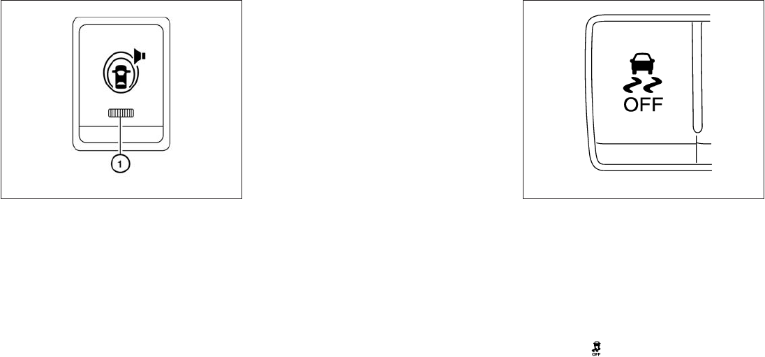
The warning systems switch is used to turn on
and off the warning systems (Forward Collision
Warning (FCW), Lane Departure Warning
(LDW) and Blind Spot Warning (BSW) systems)
that are activated using the settings menu on the
vehicle information display (VID).
When the warning systems switch is turned off,
the indicator 䊊
1on the switch is off. The indicator
will also be off if all of the warning systems are
deactivated using the settings menu.
The FCW system will sound a warning chime and
the vehicle ahead detection indicator light blinks
to alert the driver if the vehicle is traveling close to
the vehicle ahead. (See “Forward Collision
Warning (FCW) system” in the “Starting and
driving” section).
The LDW system will sound a warning chime and
blink LDW/LDP indicator light (orange) to alert
the driver if the vehicle is traveling close to either
the left or the right of a traveling lane with detect-
able lane markers. (See “Lane Departure Warn-
ing (LDW) system/Lane Departure Prevention
(LDP) system” in the “Starting and driving” sec-
tion).
The BSW system will turn on the BSW/Blind
Spot Intervention (BSI) indicator lights, located
next to the outside mirrors, if the radar sensors
detect a vehicle in the detection zone. If the turn
signal is activated in the direction of the detected
vehicle, a chime sounds twice and the BSW/BSI
indicator light will flash. (See “Blind Spot Warn-
ing (BSW) system/Blind Spot Intervention™
(BSI) system” in the “Starting and driving” sec-
tion).
The vehicle should be driven with the Vehicle
Dynamic Control (VDC) system on for most driv-
ing conditions.
If the vehicle is stuck in mud or snow, the VDC
system reduces the engine output to reduce
wheel spin. The engine speed will be reduced
even if the accelerator is depressed to the floor. If
maximum engine power is needed to free a stuck
vehicle, turn the VDC system off.
To turn off the VDC system, push the VDC OFF
switch. The indicator will come on.
Push the VDC OFF switch again or restart the
engine to turn on the system. See “Vehicle Dy-
namic Control (VDC) system” in the “Starting and
driving” section.
LIC2225 SIC4336
WARNING SYSTEMS SWITCH (if so
equipped)
VEHICLE DYNAMIC CONTROL (VDC)
OFF SWITCH
2-40 Instruments and controls
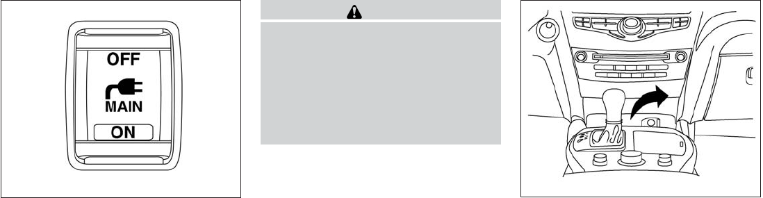
To use the outlets for devices that require 120v
power, place the ignition in the ON position and
push the power inverter switch.
The switch will illuminate when enabled.
CAUTION
●Use power outlets with the engine run-
ning to avoid discharging the vehicle
battery.
●Do not attempt to use this while driving.
●Do not use double adapters or more
than one electrical accessory, doing so
could significantly drain the battery of
your vehicle.
12V OUTLETS
The power outlets are for powering electrical
accessories such as cellular telephones. They
are rated at 12 volt, 120W (10A) maximum.
The power outlets are powered only when the
ignition switch is in the ACC or ON position.
LIC2231
Instrument Panel
LIC2238
POWER INVERTER SWITCH (if so
equipped)
POWER OUTLETS
Instruments and controls 2-41

CAUTION
●The outlet and plug may be hot during
or immediately after use.
●Only certain power outlets are designed
for use with a cigarette lighter unit. Do
not use any other power outlet for an
accessory lighter. See your INFINITI re-
tailer for additional information.
●Do not use with accessories that exceed
a 12 volt, 120W (10A) power draw.
●Do not use double adapters or more
than one electrical accessory.
●Use power outlets with the engine run-
ning to avoid discharging the vehicle
battery.
●Avoid using power outlets when the air
conditioner, headlights or rear window
defroster is on.
●Before inserting or disconnecting a
plug, be sure the electrical accessory
being used is turned OFF.
●Push the plug in as far as it will go. If
good contact is not made, the plug may
overheat or the internal temperature
fuse may open.
●When not in use, be sure to close the
cap. Do not allow water or any other
liquid to contact the outlet.
2nd Row
LIC2207
Cargo Area
LIC2236
2-42 Instruments and controls

120V OUTLET (if so equipped)
CAUTION
●The outlet and plug may be hot during
or immediately after use.
●Use power outlets with the engine run-
ning to avoid discharging the vehicle
battery.
●Do not use accessories that exceed a
120V, 150W power draw. Do not use
double adaptors or more than one elec-
trical accessory.
●Avoid using power outlets when the air
conditioner, headlights or rear window
defroster is on.
●Before inserting or disconnecting a
plug, be sure the electrical accessory
being used is turned OFF.
●Push the plug in as far as it will go. If
good contact is not made, the plug may
overheat or the internal temperature
fuse may open.
●When not in use, be sure to close the
cap. Do not allow water or any other
liquid to contact the outlet.
MAP POCKETS
2nd Row
LIC2215 LIC2211
STORAGE
Instruments and controls 2-43

SEATBACK POCKETS
There are two seatback pockets located on the
back of the driver and passenger seats. The
pockets can be used to store maps.
SUNGLASSES HOLDER
To open the sunglasses holder, push and release
䊊
1.
Only store one pair of sunglasses in the holder.
WARNING
Keep the sunglasses holder closed while
driving to prevent an accident.
CAUTION
●Do not use for anything other than
sunglasses.
●Do not leave sunglasses in the sun-
glasses holder while parking in direct
sunlight. The heat may damage the
sunglasses.
LIC2232 SIC4344
2-44 Instruments and controls

CUP HOLDERS CAUTION
Do not recline the rear seatback when you
use the cup holders on the rear armrest.
Doing so may cause the beverages to spill
over, and if they are hot, they may scald
the passengers.
CAUTION
●Avoid abrupt starting and braking when
the cup holder is being used to prevent
spilling the drink. If the liquid is hot, it
can scald you or your passenger.
●Use only soft cups in the cup holder.
Hard objects can injure you in an
accident.
Front console
LIC2249
Bench seat
LIC2212
3rd row
LIC2242
Instruments and controls 2-45
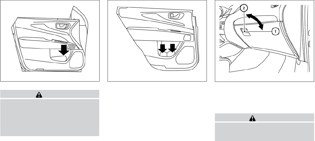
CAUTION
●Do not use bottle holder for any other
objects that could be thrown about in
the vehicle and possibly injure people
during sudden braking or an accident.
●Do not use bottle holder for open liquid
containers.
GLOVE BOX
Open the glove box by pulling the handle. Use the
master key when locking 䊊
1or unlocking 䊊
2the
glove box.
WARNING
Keep glove box lid closed while driving to
help prevent injury in an accident or a
sudden stop.
Bottle holder — front
LIC2209
Bottle holder — rear
LIC2210 LIC2243
2-46 Instruments and controls

CONSOLE BOX
Upper half
Pull up on the driver’s side latch to open the
upper half of the console box.
The upper half of the console box may be used for
storage of cellular phones. An access hole is
provided at the front of the upper half of the
console box for a phone or iPod® cord routing to
the power outlet.
Lower half
Pull up on the passenger’s side latch to open the
lower half of the console box. A power outlet is
located inside the console box and there is stor-
age for compact discs.
STORAGE TRAY
WARNING
Do not place sharp objects in the trays to
help prevent injury in an accident or sud-
den stop.
WIC1120 WIC1121 LIC2214
Instruments and controls 2-47

LUGGAGE HOOKS
When securing items using luggage hooks lo-
cated on the back of the seat or side finisher do
not apply a load over more than 6.5 lbs (29 N) to
a single hook.
The luggage hooks that are located on the floor
should have loads less then 110 lbs (490 N) to a
single hook.
The luggage hooks can be used to secure cargo
with ropes or other types of straps.
WARNING
●Properly secure all cargo with ropes or
straps to help prevent it from sliding or
shifting. Do not place cargo higher than
the seatbacks. In a sudden stop or col-
lision, unsecured cargo could cause
personal injury.
●Use suitable ropes and hooks to secure
cargo.
●Never allow anyone to ride in the lug-
gage area. It is extremely dangerous to
ride in a cargo area inside of a vehicle.
In a collision, people riding in these
areas are more likely to be seriously
injured or killed.
●Do not allow people to ride in any area
of your vehicle that is not equipped with
seats and seat belts.
●The child restraint top tether strap may
be damaged by contact with items in
the cargo area. Secure any items in the
cargo area. Your child could be seri-
ously injured or killed in a collision if
the top tether strap is damaged.
●Be sure everyone in your vehicle is in a
seat and using a seat belt properly.
CARGO AREA STORAGE BIN
To access the floor storage area, push down 䊊
1
to raise the handle, then pull up on the handle to
lift the luggage board.
LIC2208 LIC2244
2-48 Instruments and controls

ROOF RACK (if so equipped)
Genuine NISSAN accessory cross bars are avail-
able through your INFINITI retailer. Contact an
INFINITI retailer for crossbar or other equipment
information.
Always distribute the luggage evenly on the cross
bars (if so equipped). Do not load more than
150 lb (68 kg) on the cross bars (if so equipped).
Observe the maximum load limit shown on the
cross bars (if so equipped) or roof carriers when
you attach them on the roof cross bars (if so
equipped). Contact an INFINITI retailer for cross-
bar or other equipment information.
Do not apply any load directly to the roof side
rails. Cross bars (if so equipped) must be in-
stalled before applying load/cargo/luggage to
the roof of the vehicle.
Be careful that your vehicle does not exceed the
Gross Vehicle Weight Rating (GVWR) or its
Gross Axle Weight Rating (GAWR front and
rear). The GVWR and GAWR are located on the
F.M.V.S.S. or C.V. M.S.S. certification label (lo-
cated on the driver’s door pillar). For more infor-
mation regarding GVWR and GAWR, see “Ve-
hicle loading information” in the “Technical and
customer information” section.
WARNING
●Drive extra carefully when the vehicle is
loaded at or near the cargo carrying
capacity, especially if the significant
portion of that load is carried on the
cross bars (if so equipped).
●Heavy loading of the cross bars (if so
equipped) has the potential to affect the
vehicle stability and handling during
sudden or unusual handling
maneuvers.
●Roof rack cross bars (if so equipped)
should be evenly distributed.
●Do not exceed maximum roof rack cross
bars (if so equipped) load.
●Properly secure all cargo with ropes or
straps to help prevent it from sliding or
shifting. In a sudden stop or collision,
unsecured cargo could cause personal
injury.
CAUTION
Always install the cross bars (if so
equipped) onto the roof side rails before
loading cargo of any kind. Loading cargo
directly onto the roof side rails or the
vehicle’s roof may cause vehicle damage.
LIC2368
Instruments and controls 2-49
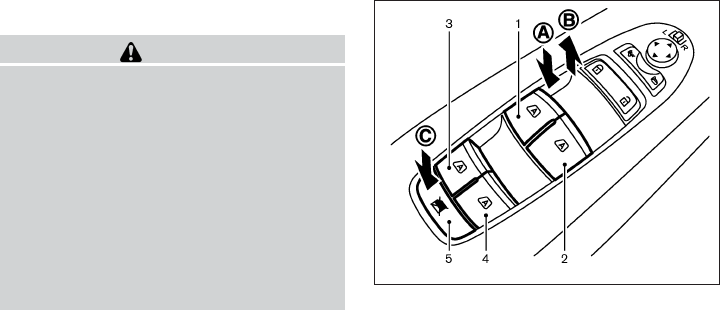
POWER WINDOWS
WARNING
●Make sure that all passengers have
their hands, etc. inside the vehicle while
it is in motion and before closing the
windows. Use the window lock switch to
prevent unexpected use of the power
windows.
●Do not leave children unattended inside
the vehicle. They could unknowingly ac-
tivate switches or controls and become
trapped in a window. Unattended chil-
dren could become involved in serious
accidents.
The power windows operate when the ignition
switch is placed in the ON position, or for a
period of time after the ignition switch is placed in
the OFF position. If the driver’s or passenger’s
door is opened during this period of time, the
power to the windows is canceled.
1. Driver side automatic switch
2. Front passenger side automatic switch
3. Left rear passenger automatic switch
4. Right rear passenger automatic switch
5. Window lock button
Driver’s side power window switch
The driver’s side control panel is equipped with
switches to open or close the front and rear
passenger windows.
The window can be partially opened by pushing
the switch down lightly until the desired window
position is reached 䊊
A. To close the window
partially, pull the switch up until the desired win-
dow position is reached 䊊
B.
Locking passengers’ windows
When the window lock button 䊊
Cis depressed,
only the driver’s side window can be opened or
closed. Push it again to cancel the window lock
function.
SIC4352
WINDOWS
2-50 Instruments and controls

Front passenger’s power window
switch
The passenger’s window switch operates only
the corresponding passenger’s window. To open
the window partially, push the switch down lightly
until the desired window position is reached. To
close the window partially, pull the switch up until
the desired window position is reached.
Rear power window switch
The rear power window switches open or close
only the corresponding windows. To partially
open the window, push the switch down lightly
until the desired window position is reached. To
partially close the window, pull the switch up
lightly until the desired window position is
reached.
Automatic operation
To fully open a window, press the window switch
down to the second detent and release it; it need
not be held. The window automatically opens all
the way. To stop the window, lift the switch up
while the window is opening.
To fully close a window, pull the switch up to the
second detent and release it; it need not be held.
To stop the window, press the switch down while
the window is closing.
Auto-reverse function
The auto-reverse function can be activated when
a window is closed by automatic operation.
SIC4353 LIC0410 LIC0410
Instruments and controls 2-51

Depending on the environment or driving
conditions, the auto-reverse function may
be activated if an impact or load similar to
something being caught in the window oc-
curs.
WARNING
There are some small distances immedi-
ately before the closed position which
cannot be detected. Make sure that all
passengers have their hands, etc., inside
the vehicle before closing the window.
If the vehicle’s battery is disconnected, replaced,
or jump started, the power window auto-reverse
function may not operate properly. If this occurs,
please contact an INFINITI retailer to re-initialize
the power window auto-reverse system.
If the control unit detects something caught in a
window equipped with automatic operation as it
is closing, the window will be immediately low-
ered.
AUTOMATIC MOONROOF
The moonroof will only operate when the ignition
switch is placed in the ON position. The auto-
matic moonroof is operational for a period of time,
even if the ignition switch is placed in the ACC or
OFF position. If the driver’s door or the front
passenger’s door is opened during this period of
time, the power to the moonroof is canceled.
Sliding the moonroof
To fully open or close the moonroof, push the
switch to the open 䊊
2or close 䊊
1position and
release it; it need not be held. The roof will
automatically open or close all the way. To stop
the roof, push the switch once more while it is
opening or closing.
Tilting the moonroof
To tilt up, first close the moonroof, then push the
switch to the tilt up position 䊊
1and release it; it
need not be held. To tilt down the moonroof, push
the switch to the tilt down position 䊊
2.
Restarting the moonroof switch
If the moonroof does not operate properly, per-
form the following procedure to initialize the
moonroof operation system.
1. If the moonroof is open, close it fully by
repeatedly pushing the moonroof switch to
the close position 䊊
1to tilt the moonroof up.
2. Push and hold the switch to the close posi-
tion 䊊
1.
3. Release the moonroof switch after the
moonroof moves slightly up and down.
4. Push and hold the switch to the open posi-
tion 䊊
2to fully tilt the moonroof down.
5. Check if the moonroof switch operates nor-
mally.
SIC4355
MOONROOF
2-52 Instruments and controls

If the moonroof does not operate properly after
performing the procedure above, have your ve-
hicle checked by an INFINITI retailer.
Auto-reverse function (when closing or
tilting down the moonroof)
The auto-reverse function can be activated when
the moonroof is closed or tilted down by auto-
matic operation when the ignition switch is
placed in the ON position or for a period of time
after the ignition switch is placed in the OFF
position.
Depending on the environment or driving
conditions, the auto-reverse function may
be activated if an impact or load similar to
something being caught in the moonroof
occurs.
WARNING
There are some small distances immedi-
ately before the closed position which
cannot be detected. Make sure that all
passengers have their hands, etc., inside
the vehicle before closing the moonroof.
When closing:
If the control unit detects something caught in the
moonroof as it moves to the front, the moonroof
will immediately open backward.
When tilting down:
If the control unit detects something caught in the
moonroof as it tilts down, the moonroof will im-
mediately tilt up.
If the auto-reverse function malfunctions and re-
peats opening or tilting up the moonroof, keep
pushing the tilt down switch within 5 seconds
after it happens; the moonroof will fully close
gradually. Make sure nothing is caught in the
moonroof.
WARNING
●In an accident you could be thrown from
the vehicle through an open moonroof.
Always use seat belts and child
restraints.
●Do not allow anyone to stand up or
extend any portion of their body out of
the moonroof opening while the vehicle
is in motion or while the moonroof is
closing.
CAUTION
●Remove water drops, snow, ice or sand
from the moonroof before opening.
●Do not place heavy objects on the
moonroof or surrounding area.
Sunshade
Open and close the sunshade by sliding it for-
ward or backward.
If the moonroof does not close
Have your INFINITI retailer check and repair the
moonroof.
Instruments and controls 2-53

When the ON switch 䊊
1is pressed, the footwell
lights, step lights, map lights and rear personal
lights will automatically turn on and stay on for a
period of time when:
●The doors are unlocked by the Intelligent
Key, a key or the request switch while all
doors are closed and the ignition switch is in
the OFF position.
●The driver’s door is opened and then closed
while the key is removed from the ignition
switch.
●When individually pushed.
When the OFF switch 䊊
2is pushed, the interior
lights do not illuminate even when pushed.
NOTE:
The footwell lights and step lights illumi-
nate when the driver and passenger doors
are open regardless of the interior light
switch position. These lights will turn off
automatically after a period of time while
doors are open to prevent the battery from
becoming discharged.
CAUTION
Do not use for extended periods of time
with the engine stopped. This could result
in a discharged battery. CONSOLE LIGHT
The console light 䊊
1will turn on whenever the
parking lights or headlights are illuminated.
The console light brightness can be adjusted
with the illumination brightness control.
SIC4357 LIC2213
INTERIOR LIGHT
Instruments and controls 2-55
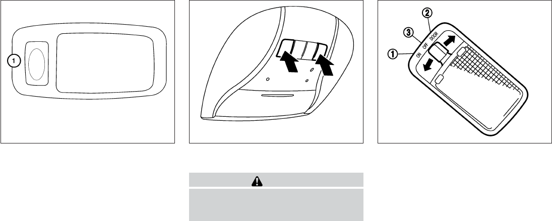
To turn on the personal lights, press and release
the switch 䊊
1.
To turn the personal lights off, press and release
the switch 䊊
1.
To turn the map lights on, press the switches. To
turn them off, press the switches again.
CAUTION
Do not use for extended periods of time
with the engine stopped. This could result
in a discharged battery.
The cargo light on the overhead trim has a three-
position switch. To operate, push the switch to
the desired position.
䊊
1ON: The light is illuminated.
䊊
2DOOR: The light illuminates when the lift-
gate is opened. The light turns off when the
liftgate is closed.
䊊
3OFF: The light does not illuminate regardless
of liftgate position or lock status.
LIC1413 SIC4356 SIC2063A
PERSONAL LIGHTS MAP LIGHTS CARGO LIGHT
2-56 Instruments and controls
Do not stand on your vehicle to perform
the next steps.
4. At the receiver located on the garage door
opener motor in the garage, locate the
“learn” or “smart” button (the name and color
of the button may vary by manufacturer but it
is usually located near where the hanging
antenna wire is attached to the unit). If there
is difficulty locating the button, reference the
garage door opener’s manual.
5. Press and release the “learn” or “smart” but-
ton.
6. Return to the vehicle and firmly press and
hold the trained HomeLink® button for two
seconds and release. Repeat the
“press/hold/release” sequence up to 3
times to complete the training process.
HomeLink® should now activate your rolling
code equipped device.
7.
If you have any questions or are having diffi-
culty programming your HomeLink® buttons,
refer to the HomeLink® web site at:
www.homelink.com or call 1-800-355-3515.
PROGRAMMING HOMELINK® FOR
CANADIAN CUSTOMERS AND
GATE OPENERS
Canadian radio-frequency laws require transmit-
ter signals to “time-out” (or quit) after several
seconds of transmission – which may not be long
enough for HomeLink® to pick up the signal
during training. Similar to this Canadian law,
some U.S. gate operators are designed to “tim-
eout” in the same manner.
If you live in Canada or you are having difficulties
training a gate operator or garage door opener
by using the “Training” procedures, replace
“Programming HomeLink®” Step 2 with the fol-
lowing:
NOTE:
When programming a garage door opener,
etc., unplug the device during the “cycling”
process to prevent possible damage to the
garage door opener components.
1. See “Programing HomeLink®”step 1 earlier
in this section.
2. Using both hands, simultaneously press and
hold the desired HomeLink® button and the
hand-held transmitter button. During train-
ing, your hand-held transmitter may auto-
matically stop transmitting. Continue to
press and hold the desired HomeLink® but-
ton while you press and re-press (“cycle”)
your hand-held transmitter every two sec-
onds until the frequency signal has been
learned. The HomeLink® indicator light will
flash slowly and then rapidly after several
seconds upon successful training. DO NOT
release until the HomeLink® indicator light
flashes slowly and then rapidly. When the
indicator light flashes rapidly, both buttons
may be released. The rapid flashing indi-
cates successful training.
Proceed with “Programming HomeLink®”
step 3 to complete.
If the device was unplugged during the pro-
gramming procedure, remember to plug it
back in when programming is completed.
OPERATING THE HOMELINK®
UNIVERSAL TRANSCEIVER
The HomeLink® Universal Transceiver, after it is
programmed, can be used to activate the pro-
grammed device. To operate, simply press and
release the appropriate programmed
HomeLink® Universal Transceiver button. The
amber indicator light will illuminate while the sig-
nal is being transmitted.
For convenience, the hand-held transmitter of the
device may also be used at any time.
Instruments and controls 2-59
MEMO
2-62 Instruments and controls

3 Pre-driving checks and adjustments
Keys.............................................3-2
INFINITI Intelligent Key ..........................3-2
INFINITI Vehicle Immobilizer System keys..........3-4
Doors ............................................3-4
Locking with key................................3-5
Locking with inside lock knob ....................3-5
Locking with power door lock switch .............3-6
Automatic door locks ...........................3-6
Child safety rear door lock.......................3-7
INFINITI Intelligent Key System ......................3-7
Operating range................................3-9
Door locks/unlocks precaution ...................3-9
INFINITI Intelligent Key Operation ...............3-10
How to use the remote keyless entry
function ......................................3-13
Warning signals ...............................3-16
Troubleshooting guide .........................3-17
Remote Engine Start (if so equipped) ...............3-18
Remote engine start operating range ............3-18
Remote starting the vehicle .....................3-18
Extending engine run time ......................3-19
Canceling a remote start .......................3-19
Conditions the remote start will not work . . . ......3-19
Hood ...........................................3-20
Liftgate..........................................3-20
Operating the power liftgate ....................3-21
Power liftgate main switch ......................3-23
Liftgate release lever ...........................3-23
Liftgate position setting ........................3-24
Fuel-filler door ...................................3-24
Opening the fuel-filler door .....................3-24
Fuel-filler cap . . ...............................3-25
Tilt/telescopic steering ............................3-27
Tilt and telescopic operation ....................3-27
Sun visors .......................................3-28
Vanity mirrors . . ...............................3-29
Mirrors ..........................................3-29
Automatic anti-glare rearview mirror .............3-29
Outside mirrors ...............................3-30
Automatic drive positioner (if so equipped) ..........3-31
Memory storage function .......................3-32
Entry/exit function .............................3-34
Setting memory function........................3-34
System operation..............................3-35

A key number plate is supplied with your keys.
Record the key number and keep it in a safe place
(such as your wallet), not in the vehicle. If you lose
your keys, see an INFINITI retailer for duplicates
by using the key number. INFINITI does not re-
cord key numbers so it is very important to keep
track of your key number plate.
A key number is only necessary when you have
lost all keys and do not have one to duplicate
from. If you still have a key, your INFINITI retailer
can duplicate it.
1. Intelligent Key (2 sets)
2. Mechanical key
3. Key number plate (1 plate)
INFINITI INTELLIGENT KEY
Your vehicle can only be driven with the Intelligent
Keys which are registered to your vehicle’s Intel-
ligent Key system components and INFINITI Ve-
hicle Immobilizer System components. As many
as 4 Intelligent Keys can be registered and used
with one vehicle. The new keys must be regis-
tered by an INFINITI retailer prior to use with the
Intelligent Key system and INFINITI Vehicle Im-
mobilizer System of your vehicle. Since the reg-
istration process requires erasing all memory in
the Intelligent Key components when registering
new keys, be sure to take all Intelligent Keys that
you have to the INFINITI retailer.
CAUTION
Listed below are conditions or occurrences
which will damage the Intelligent Key:
●Do not allow the Intelligent Key, which
contains electrical components, to
come into contact with water or salt
water. This could affect the system
function.
Type A
WPD0427
Type B
LPD2052
KEYS
3-2 Pre-driving checks and adjustments
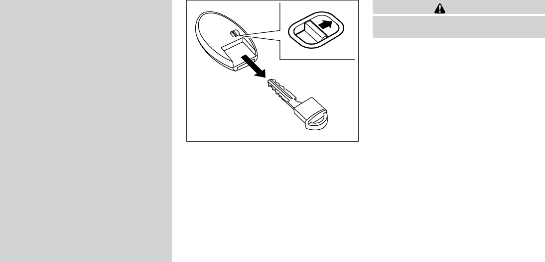
●Do not drop the Intelligent Key.
●Do not strike the Intelligent Key sharply
against another object.
●Do not change or modify the Intelligent
Key.
●Wetting may damage the Intelligent
Key. If the Intelligent Key gets wet, im-
mediately wipe until it is completely dry.
●Do not place the Intelligent Key for an
extended period in an area where tem-
peratures exceed 140°F (60°C).
●Do not attach the Intelligent Key with a
key holder that contains a magnet.
●Do not place the Intelligent Key near
equipment that produces a magnetic
field, such as a TV, audio equipment and
personal computers.
If an Intelligent Key is lost or stolen,
INFINITI recommends erasing the ID code
of that Intelligent Key from the vehicle.
This may prevent the unauthorized use of
the Intelligent Key to operate the vehicle.
For information regarding the erasing
procedure, contact an INFINITI retailer.
Mechanical key
The Intelligent Key contains the mechanical key.
To remove the mechanical key, release the lock
knob on the back of the Intelligent Key.
To install the mechanical key, firmly insert it into
the Intelligent Key until the lock knob returns to
the lock position.
Use the mechanical key to lock or unlock the
driver’s door and glove box.
CAUTION
Always carry the mechanical key installed
in the Intelligent Key slot.
See “Doors” in this section and “Storage” in the
“Instruments and controls”section of this manual.
Valet hand-off
When you have to leave a key with a valet, give
them the Intelligent Key itself and keep the me-
chanical key with you to protect your belongings.
To prevent the glove box from being opened
during valet hand-off, follow the procedure be-
low.
1. Remove the mechanical key from the Intelli-
gent Key.
2. Lock the glove box with the mechanical key.
3. Hand the Intelligent Key to the valet and
keep the mechanical key with you.
See “Storage” in the “Instruments and controls”
section of this manual.
SPA1951
Pre-driving checks and adjustments 3-3

INFINITI VEHICLE IMMOBILIZER
SYSTEM KEYS
You can only drive your vehicle using the master
or valet keys which are registered to the INFINITI
Vehicle Immobilizer System components in your
vehicle. These keys have a transponder chip in
the key head.
The master key can be used for all the locks.
The valet key cannot be used for the glove box
lock.
To protect belongings when you leave a key with
someone, give them the valet key only.
Never leave these keys in the vehicle.
Additional or replacement keys:
If you still have a key, the key number is not
necessary when you need extra INFINITI Vehicle
Immobilizer System keys. Your retailer can dupli-
cate your existing key. As many as five INFINITI
Vehicle Immobilizer System keys can be used
with one vehicle. You should bring all INFINITI
Vehicle Immobilizer System keys that you have to
your INFINITI retailer for registration. This is be-
cause the registration process will erase the
memory of all key codes previously registered
into the INFINITI Vehicle Immobilizer System. Af-
ter the registration process, these components
will only recognize keys coded into the INFINITI
Vehicle Immobilizer System during registration.
Any key that is not given to your retailer at the time
of registration will no longer be able to start your
vehicle.
CAUTION
Do not allow the immobilizer system key,
which contains an electrical transponder,
to come into contact with water or salt
water. This could affect system function.
When the doors are locked using one of the
following methods, the doors can not be opened
using the inside or outside door handles. The
doors must be unlocked to open the doors.
WARNING
●Always have the doors locked while
driving. Along with the use of seat belts,
this provides greater safety in the event
of an accident by helping to prevent
persons from being thrown from the
vehicle. This also helps keep children
and others from unintentionally open-
ing the doors, and will help keep out
intruders.
●Before opening any door, always look
for and avoid oncoming traffic.
●Do not leave children unattended inside
the vehicle. They could unknowingly ac-
tivate switches or controls. Unattended
children could become involved in seri-
ous accidents.
DOORS
3-4 Pre-driving checks and adjustments

LOCKING WITH POWER DOOR
LOCK SWITCH
To lock all the doors without a key, push the door
lock switch (driver’s or front passenger’s side) to
the lock position 䊊
1. When locking the door this
way, be certain not to leave the key inside the
vehicle.
To unlock all the doors without a key, push the
door lock switch (driver’s or front passenger’s
side) to the unlock position 䊊
2.
Lockout protection
When the power door lock switch is moved to the
lock position and any door is open, all doors will
lock and unlock automatically. With the Intelligent
Key left in the vehicle and any door is open, all
doors will unlock automatically and a chime will
sound after the door is closed.
These functions help to prevent the Intelligent
Key from being accidentally locked inside the
vehicle.
AUTOMATIC DOOR LOCKS
●All doors lock automatically when the vehicle
speed reaches 15 MPH (24 km/h).
●All doors unlock automatically when the ig-
nition is placed in the OFF position.
The automatic unlock function can be de-
activated or activated. To deactivate or acti-
vate the automatic door unlock system, perform
the following procedure:
1. Close all doors.
2. Place the ignition switch in the ON position.
3. Within 20 seconds of performing Step 2,
push and hold the power door lock switch to
the position (UNLOCK) for more than
5 seconds.
4. When activated, the hazard indicator will
flash twice. When deactivated, the hazard
indicator will flash once.
5. The ignition switch must be placed in the
OFF and ON position again between each
setting change.
When the automatic door unlock system is deac-
tivated, the doors do not unlock when the ignition
switch is placed in the OFF position. To unlock
the door manually, use the inside lock knob or the
power door lock switch (driver’s or front passen-
ger’s side).
NOTE:
The automatic door unlock function can be
changed using the Vehicle Settings in the
vehicle information display. The “Auto
Door Unlock” choices are:
●Off
●IGN OFF
●Shift into P
SPA2727
3-6 Pre-driving checks and adjustments

●To prevent the Intelligent Key from being left
inside the vehicle, make sure you carry the
Intelligent Key with you and then lock the
doors.
●Do not pull the door handle before pushing
the door handle request switch. The door
will be unlocked but will not open. Release
the door handle once and pull it again to
open the door.
INFINITI INTELLIGENT KEY
OPERATION
You can lock or unlock the doors without taking
the Intelligent Key out of your pocket or bag.
When you carry the Intelligent Key with you, you
can lock or unlock all doors by pushing the door
handle request switch within the range of opera-
tion.
Locking doors
1. Move the shift lever to the P (Park) position,
place the ignition switch in the LOCK posi-
tion and make sure you carry the Intelligent
Key with you.
2. Close all doors.
3. Push any door handle request switch while
carrying the Intelligent Key with you.
4. All doors and the rear liftgate will lock.
5. The hazard warning lights flash twice and
the outside buzzer sounds once.
LPD2057 LPD2058
3-10 Pre-driving checks and adjustments
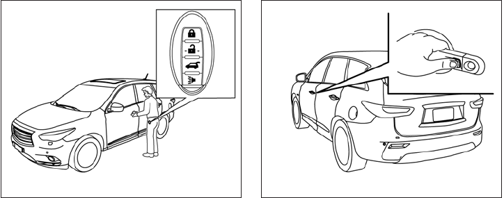
Unlocking doors
1. Carry the Intelligent Key.
2. Push the door handle request switch.
3. The hazard warning lights flash once and the
outside buzzer sounds once.
4. Push the door handle request switch again
within 1 minute to unlock all doors.
For power liftgate opening:
1. Carry the Intelligent Key.
2. Press the power liftgate request switch.
NOTE:
Request switches for all doors and liftgate
can be deactivated when the I-Key Door
Lock setting is switched to OFF in the Ve-
hicle Settings of the vehicle information
display. For additional information, see
“Vehicle information display” in the “In-
struments and controls” section of this
manual.
If a door handle is pulled while unlocking the
doors, that door may not be unlocked. Returning
the door handle to its original position will unlock
the door. If the door does not unlock after return-
ing the door handle, push the door handle re-
quest switch to unlock the door.
All doors will be locked automatically unless one
of the following operations is performed within
1 minute after pushing the request switch.
●Opening any door.
●Pushing the ignition switch.
The interior light timer illuminates for a period of
time when a door is unlocked and the room light
switch is in the DOOR position.
The interior light can be turned off without waiting
by performing one of the following operations:
●Placing the ignition switch in the ON posi-
tion.
●Locking the doors with the remote controller.
●Switching the room light switch to the OFF
position.
●Switching the Auto Room Lamp to the OFF
position in Vehicle Settings of the vehicle
information display. See “Vehicle information
display” in the “Instruments and controls”
section.
LPD2058 LPD2059
3-12 Pre-driving checks and adjustments
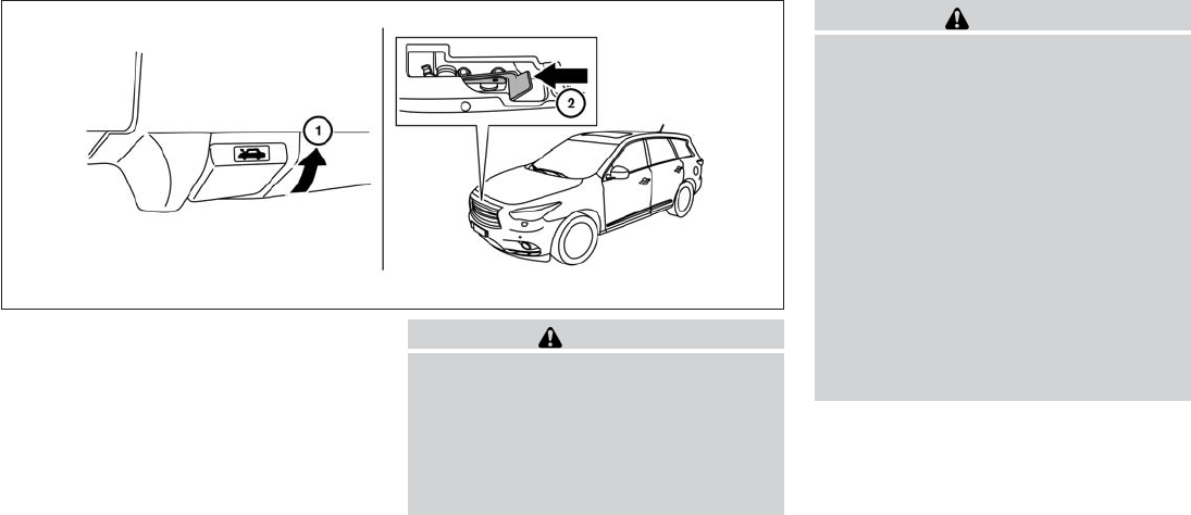
䊊
1Pull the hood lock release handle located
below the driver side instrument panel. The
hood will spring up slightly.
䊊
2Push the lever at the front of the hood to the
side as illustrated with your fingertips and
raise the hood.
When closing the hood, lower it slowly and make
sure it locks into place.
WARNING
●Make sure the hood is completely
closed and latched before driving. Fail-
ure to do so could cause the hood to fly
open and result in an accident.
●If you see steam or smoke coming from
the engine compartment, to avoid injury
do not open the hood.
WARNING
●Always be sure the liftgate has been
closed securely to prevent it from open-
ing while driving.
●Do not drive with the liftgate open. This
could allow dangerous exhaust gases
to be drawn into the vehicle. See “Ex-
haust gas” in the “Starting and driving”
section of this manual.
●Do not leave children unattended inside
the vehicle. They could unknowingly ac-
tivate switches or controls. Unattended
children could become involved in seri-
ous accidents.
●Always be sure that hands and feet are
clear of the door frame to avoid injury
while closing the liftgate.
LPD2061
HOOD LIFTGATE
3-20 Pre-driving checks and adjustments

OPERATING THE POWER LIFTGATE
WARNING
●Make sure that all passengers have
their hands, etc., inside the vehicle be-
fore closing the liftgate.
●Do not leave children unattended inside
the vehicle. They could unknowingly ac-
tivate switches or controls. Unattended
children could become involved in seri-
ous accidents.
Liftgate switch
LPD2063
Instrument panel switch
LPD0249
Liftgate opener switch
LPD2069
Pre-driving checks and adjustments 3-21

Manual Mode:
If power operation is not available, the liftgate
may be operated manually. Power operation may
not be available if the power liftgate main switch
is in the ON position, if multiple obstacles have
been detected in a single power cycle, or if
battery voltage is low.
If the power liftgate opener switch 䊊
Ais pushed
during power open or close, the power operation
will be canceled and the liftgate can be operated
manually.
To open the liftgate manually, press the liftgate
opener switch 䊊
Aand lift the liftgate.
To close, lower and push the liftgate down securely.
POWER LIFTGATE MAIN SWITCH
The power liftgate operation can be turned on or
off by the power liftgate main switch on the
instrument panel.
When the power liftgate main switch is pushed to
the OFF position, the power operation is not
available by the power liftgate switch on the
liftgate and liftgate opener switch.
Power operation is available when in the OFF
position by the instrument panel switch and the
keyfob button.
LIFTGATE RELEASE LEVER
WARNING
●Always be sure the liftgate has been
closed securely to prevent it from open-
ing while driving.
●Do not drive with the liftgate open. This
could allow dangerous exhaust gases
to be drawn into the vehicle. See “Ex-
haust gas” in the “Starting and driving”
section of this manual.
LPD2062 SPA2547
Pre-driving checks and adjustments 3-23

To lock, close the fuel-filler door securely and
lock the doors.
FUEL-FILLER CAP
WARNING
●Gasoline is extremely flammable and
highly explosive under certain condi-
tions. You could be burned or seriously
injured if it is misused or mishandled.
Always stop the engine and do not
smoke or allow open flames or sparks
near the vehicle when refueling.
●Do not attempt to top off the fuel tank
after the fuel pump nozzle shuts off
automatically. Continued refueling may
cause fuel overflow, resulting in fuel
spray and possibly a fire.
●Use only an original equipment type
fuel-filler cap as a replacement. It has a
built-in safety valve needed for proper
operation of the fuel system and emis-
sion control system. An incorrect cap
can result in a serious malfunction and
possible injury. It could also cause
the Malfunction Indicator Light
(MIL) to come on.
●Never pour fuel into the throttle body to
attempt to start your vehicle.
●Do not fill a portable fuel container in
the vehicle or trailer. Static electricity
can cause an explosion of flammable
liquid, vapor or gas in any vehicle or
trailer. To reduce the risk of serious
injury or death when filling portable fuel
containers:
– Always place the container on the
ground when filling.
– Do not use electronic devices when
filling.
– Keep the pump nozzle in contact
with the container while you are fill-
ing it.
– Use only approved portable fuel con-
tainers for flammable liquid.
CAUTION
●Do not use E-15 or E-85 fuel in your
vehicle. For further information see the
“Fuel Recommendation” in the “Techni-
cal and consumer information” section
of this manual.
●The LOOSE FUEL CAP warning will ap-
pear if the fuel-filler cap is not properly
tightened. It may take a few driving trips
for the message to be displayed. Failure
to tighten the fuel-filler cap properly
after the LOOSE FUEL CAP warning ap-
pears may cause the Malfunction
Indicator Light (MIL) to illuminate.
●Failure to tighten the fuel-filler cap
properly may cause the Malfunc-
tion Indicator Light (MIL) to illuminate.
If the light illuminates because
the fuel-filler cap is loose or missing,
tighten or install the cap and continue
to drive the vehicle. The light
should turn off after a few driving trips.
If the light does not turn off after a
few driving trips, have the vehicle in-
spected by an INFINITI retailer.
●For additional information, see the
“Malfunction Indicator Light (MIL)” in
the “Instruments and Controls” section
in this manual.
●If fuel is spilled on the vehicle body,
flush it away with water to avoid paint
damage.
Pre-driving checks and adjustments 3-25

To remove the fuel-filler cap:
1. Turn the fuel-filler cap counterclockwise to
remove.
2. Put the fuel-filler cap on the cap holder 䊊
1
while refueling.
To install the fuel-filler cap:
1. Insert the fuel-filler cap straight into the fuel-
filler tube.
2. Turn the fuel-filler cap clockwise until a
single click is heard.
Loose Fuel Cap warning
The LOOSE FUEL CAP warning appears in the
vehicle information display when the fuel-filler
cap is not tightened correctly after the vehicle has
been refueled. It may take a few driving trips for
the message to be displayed. To turn off the
warning, perform the following:
1. Remove and install the fuel-filler cap as soon
as possible. See “Fuel-filler cap” in this sec-
tion.
2. Tighten the fuel-filler cap until it clicks.
3. Press the next button 䊊
Aon the steer-
ing wheel for about 1 second to turn off the
LOOSE FUEL CAP warning 䊊
Bafter tight-
ening the fuel-filler cap.
LPD2065 LPD2066
3-26 Pre-driving checks and adjustments

WARNING
●Do not adjust the steering wheel while
driving. You could lose control of your
vehicle and cause an accident.
●Do not adjust the steering wheel any
closer to you than is necessary for
proper steering operation and comfort.
The driver’s air bag inflates with great
force. If you are unrestrained, leaning
forward, sitting sideways or out of posi-
tion in any way, you are at greater risk of
injury or death in a crash. You may also
receive serious or fatal injuries from the
air bag if you are up against it when it
inflates. Always sit back against the
seatback and as far away as practical
from the steering wheel. Always use the
seat belts.
TILT AND TELESCOPIC OPERATION
To adjust the steering wheel move the switch 䊊
1
in the following directions:
●Adjust the steering wheel forward or back-
ward in direction 䊊
3to the desired tele-
scopic position.
●Adjust the steering wheel up or down in
direction 䊊
2to the desired tilt position.
CAUTION
For vehicles with automatic drive posi-
tioner: Failure to reset the tilt and tele-
scoping functions of the steering wheel,
after the vehicle’s battery has been dis-
charged, may prevent the steering wheel
position from being adjusted.
For vehicles with automatic drive positioner: Both
the tilt and telescopic steering operation must be
reset after the vehicle’s battery has been dis-
charged in order to prevent the tilt and telescopic
operation from locking in one position. When the
battery has been recharged or replaced, perform
the following:
●For telescopic operation: Adjust the switch
䊊
1so the steering wheel moves to the most
forward and backward position 䊊
3that can
be reached.
●For tilt operation: Adjust the switch 䊊
1so
the steering wheel moves to the highest
position 䊊
2that can be reached.
Performing these operations resets the range of
the steering wheel’s tilt and telescopic function.
WPD0366
TILT/TELESCOPIC STEERING
Pre-driving checks and adjustments 3-27

Entry/Exit function
The automatic drive positioner system will make
the steering wheel move up automatically when
the driver’s door is opened and the ignition
switch is in the LOCK position. This lets the driver
get into and out of the seat more easily. The
steering wheel moves back into position when
the driver’s door is closed and the ignition switch
is pushed.
For more information, see “Automatic drive posi-
tioner” in this section.
䊊
1To block glare from the front, swing down the
sun visor.
䊊
2To block glare from the side, remove the sun
visor from the center mount and swing the
visor to the side.
䊊
3Slide the extension sun visor in or out as
needed.
CAUTION
●Do not store the sun visor before return-
ing the extension to its original
position.
●Do not pull the extension sun visor
forcedly downward.
WPD0315
SUN VISORS
3-28 Pre-driving checks and adjustments

Selecting the memorized position
Set the shift lever to the P (Park) position, then:
●Within 45 seconds of opening the driver’s
door, push the memory switch (1 or 2) or
●Place the ignition switch in the ON position
and push the memory switch (1 or 2).
The driver’s seat, steering column, and outside
mirrors will move to the memorized position with
the indicator light blinking, and then the light will
stay on for approximately 5 seconds.
ENTRY/EXIT FUNCTION
This system is designed so that the driver’s seat
and automatic operation steering column will au-
tomatically move when the shift lever is in the P
(Park) position. This allows the driver to get into
and out of the driver’s seat more easily.
The driver’s seat will slide backward and the
steering column will move up:
●When the driver’s door is opened with the
ignition switch placed in the LOCK position.
●When the ignition switch is turned from
ACC to LOCK with the driver’s door open.
The driver’s seat and steering wheel will return to
the previous position:
●When the driver’s door is closed with the
ignition switch placed in the LOCK position.
●When the ignition switch is turned from
ACC to ON while the shift lever is in the P
(Park) position.
The entry/exit function can be adjusted or can-
celed through the Vehicle Settings in the vehicle
information display by performing the following:
●Switch the Exit Seat Slide from ON to OFF.
●Switch the Exit Steering UP from ON to
OFF.
Restarting the entry/exit function
If the battery cable is disconnected or if the fuse
opens, the entry/exit function will be disabled.
Drive the vehicle over 25 MPH (40 km/h) to
restart the entry/exit function. You can also restart
the entry/exit function using the following proce-
dure.
1. Connect the battery cable or replace the
fuse.
2. Open and close the driver’s door more than
2 times with the ignition switch in the LOCK
position.
The entry/exit function should now work properly.
SETTING MEMORY FUNCTION
The position of the following settings can be
linked to the Intelligent Key and the memorized
settings can be available for each Intelligent Key.
●Climate control system
●Navigation system (if so equipped)
●Audio system
To use the memory function, set the climate,
navigation and audio systems to the driver’s pre-
ferred settings. Lock the doors with the Intelligent
Key. Each Intelligent Key may be set with the
driver’s individual preferences. When a new In-
telligent Key is used, “Connection with the key
has been done” will be displayed on the screen
and the memorized settings are available.
To engage the memorized settings, perform the
following:
1. Carry the Intelligent Key that is linked to the
memorized settings.
2. Unlock the doors by pushing the driver’s
door handle request switch or the
UNLOCK button on the Intelligent
Key.
3. Place the ignition switch in the “ON” posi-
tion. The settings linked to the Intelligent Key
will start.
3-34 Pre-driving checks and adjustments
MEMO
3-36 Pre-driving checks and adjustments

4 Monitor, climate, audio, phone and voice
recognition systems
Control panel buttons — color screen without
Navigation System (if so equipped) ..................4-4
How to use the INFINITI controller ................4-5
How to select menus on the screen ..............4-6
How to use the STATUS button ..................4-6
How to use the INFO button .....................4-6
How to use the SETTING button .................4-8
OFF button .............................4-10
Control panel buttons — color screen with
Navigation System (if so equipped) .................4-11
How to use the INFINITI controller ...............4-12
How to use the touch screen ...................4-12
Menu options .................................4-14
How to select menus on the screen .............4-15
How to use the STATUS button .................4-15
How to use the INFO button ....................4-16
How to use the SETTING button ................4-18
OFF button .............................4-21
Image viewer (if so equipped) ......................4-22
Using the image viewer ........................4-22
RearView Monitor (if so equipped)..................4-24
How to read the displayed lines .................4-24
How to park with predicted course lines..........4-25
Difference between predictive and actual
distances .....................................4-26
How to adjust the screen .......................4-28
Operating tips.................................4-28
Around View® Monitor (if so equipped) .............4-29
Available views ................................4-30
Difference between predictive and actual
distances .....................................4-35
How to switch the display ......................4-37
Parking Sensor (if so equipped) Rear Center
Sonar (if so equipped) .........................4-38
Moving Object Detection (MOD) ................4-40
How to adjust the screen view ..................4-42
Around View Monitor settings ...................4-43
View malfunction ..............................4-44
Operating tips.................................4-45
Vents ...........................................4-46
Heater and air conditioner (automatic) ..............4-47
Automatic operation ...........................4-48
Manual operation ..............................4-48
Operating tips.................................4-49
CLIMATE setting screen........................4-50
Servicing air conditioner...........................4-53
Audio system ....................................4-54
Radio ........................................4-54
FM radio reception . . ..........................4-54
AM radio reception . . ..........................4-54
Satellite radio reception (if so equipped) .........4-55
Audio operation precautions ....................4-55
FM/AM/SAT radio with compact disc (CD)
player (if so equipped) .........................4-70
Digital Versatile Disc (DVD) Player
Operation (models with Navigation System) ......4-79
USB interface .................................4-82
iPod®* player operation ........................4-87
Bluetooth® streaming audio (if so equipped) .....4-91
CD care and cleaning ..........................4-94
Steering wheel switch for audio control ..........4-94
Antenna ......................................4-96
Dual head restraint/headrest DVD system
(if so equipped) ..................................4-96
System components ...........................4-97
Before operating dual head restraint/
headrest DVD system .........................4-102
Playing a digital versatile disc (DVD) ............4-103
Operating tips................................4-107
Care and maintenance ........................4-108
Car phone or CB radio . . .........................4-109
Bluetooth® Hands-Free Phone System without
Navigation System (if so equipped) ................4-109
Regulatory Information ........................4-111
Using the system .............................4-111
Control buttons ..............................4-113
Getting started ...............................4-114
List of voice commands .......................4-115
Voice Adaptation (VA) mode ...................4-120
Manual control ...............................4-121
Troubleshooting guide ........................4-122
Bluetooth® Hands-Free Phone System with
Navigation System (if so equipped) ................4-123
Regulatory Information ........................4-125
Voice commands .............................
4-125
Connecting procedure ........................4-126
Vehicle Phonebook ...........................4-127
Handset phonebook ..........................4-128
Making a call.................................4-129
Receiving a call ..............................4-130
During a call .................................4-130
Ending a call .................................4-131
Phone settings ...............................4-131
Bluetooth settings ............................4-132
Call volume . .................................4-133
INFINITI Voice Recognition System
(if so equipped) .................................4-134
INFINITI Voice Recognition Standard Mode......4-134
Using the system .............................4-137
Before starting ...............................4-137
Giving voice commands .......................4-137
INFINITI Voice Recognition Alternate
Command Mode .............................4-142
Using the system .............................4-146
Speaker Adaptation function ...................4-149
Troubleshooting guide ........................4-150

Touch screen operation
With this system, the same operations as those
for the INFINITI controller are possible using the
touch screen operation.
Selecting the item:
Touch an item to select. To select the “Naviga-
tion” key, touch the “Navigation” key 䊊
1on the
screen. Touch the “BACK” key 䊊
2to return to the
previous screen.
Adjusting the item:
Touch the “+” key 䊊
1or the “⫺” key 䊊
2to adjust
the settings of an item.
Touch the up arrow 䊊
3to scroll up the page one
item at a time, or touch the double up arrow 䊊
4to
scroll up an entire page.
Touch the down arrow 䊊
5to scroll down the
page one item at a time, or touch the double
down arrow 䊊
6to scroll down an entire page.
Inputting characters:
Touch the letter or number key 䊊
1.
There are some options available when inputting
characters.
●Uppercase:
Shows uppercase characters.
●Lowercase:
Shows lowercase characters.
●Space:
Inserts a space.
LHA1227 LHA1228 LHA1230
Monitor, climate, audio, phone and voice recognition systems 4-13

●Delete:
Deletes the last inputted character with one
touch. Touch and hold the “Delete” key to
delete all of the characters.
●OK:
Completes the character input.
Touch screen maintenance
If you clean the display screen, use a dry, soft
cloth. If additional cleaning is necessary, use a
small amount of neutral detergent with a soft
cloth. Never spray the screen with water or de-
tergent. Dampen the cloth first, and then wipe the
screen.
MENU OPTIONS
The start menu can be displayed using the menu
control switch on the steering wheel controls.
1. While the MAP or STATUS screen is dis-
played, press and hold the menu control
switch until the “Menu Options” screen ap-
pears.
2. Highlight the preferred item by tilting the
menu control switch up or down. Press the
menu control switch to select the high-
lighted item.
Available items
Destination/Route:
These items are for the navigation system. See
the separate Navigation System Owner’s Manual
for details.
Info:
Displays the information screen. It is the same
screen that appears when you press the INFO
button.
Settings:
Displays the settings screen. It is the same
screen that appears when you press the SET-
TING button.
SAA2476
4-14 Monitor, climate, audio, phone and voice recognition systems
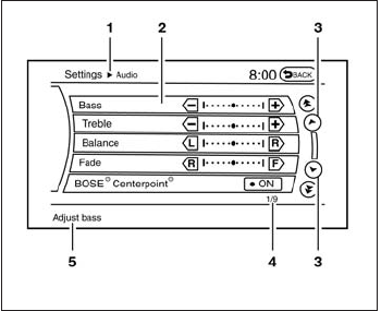
HOW TO SELECT MENUS ON THE
SCREEN
Vehicle functions are viewed on the center dis-
play screen in menus. Whenever a menu selec-
tion is made or menu item is highlighted, different
areas on the screen provide you with important
information. See the following for details.
1. Header:
Shows the path used to get to the current
screen (for example, press the SETTING
button > then select the “Audio” key).
2. Menu Selections:
Shows the options to choose within that
menu screen (for example, Bass, etc.).
3. Up/Down Movement Indicator:
Shows that the INFINITI controller may be
used to move up or down on the screen and
select more options.
4. Screen Count:
Shows the number of menu selections avail-
able for the current menu, even if they are on
multiple pages (for example, 1/9).
5. Footer/Information Line:
Provides more information (if available)
about the menu selection currently high-
lighted (for example, Adjust bass).
HOW TO USE THE STATUS
BUTTON
The STATUS button is used to display system
information. Three different split screens of infor-
mation are available. Press the STATUS button
multiple times to cycle through these screens as
follows:
Audio with Turn Information for Navigation →
Audio with Fuel Economy Information →Audio
with Climate Control Information →Audio with
Turn Information for Navigation
LHA2178
Monitor, climate, audio, phone and voice recognition systems 4-15

HOW TO USE THE INFO BUTTON
Press the INFO button. This screen sets or dis-
plays various information that is helpful for using
the vehicle. Available items include fuel economy,
maintenance, navigation and voice recognition
information.
Menu Item Result
Infiniti Connection For information on the Infiniti Connection system, see the separate Navigation System Owner’s Manual.
Fuel Economy Displays Fuel Economy menu.
Distance to Empty Displays an estimation of the distance that the vehicle can be driven before refueling. The DTE is constantly calculated based on the
amount of fuel in the fuel tank and actual fuel consumption. The display is updated every 30 seconds. When the fuel level is low, the DTE
display will change to (*).
NOTE: If the amount of fuel added while the ignition switch is OFF is small, the display just before the ignition switch is turned OFF may
continue to be displayed.
NOTE:When driving uphill or rounding curves, the fuel in the tank shifts, which may momentarily change the display.
Average Fuel Economy Displays the average fuel economy since the last reset. The display is updated every 30 seconds and 1/3 mi (500 m). After a reset or
connecting the battery cables, the display might show (**.*). Select “Reset Fuel Eco” to reset the fuel economy calculation to 0.
Resetting fuel economy The average fuel economy calculation can be reset to 0. Press the INFO button and select the “Fuel Economy” key, then select the “Reset
Fuel Eco” key using the INFINITI controller.
Fuel Economy Record Press the INFO button, then select the “Fuel Economy” key, then select the “Fuel Eco History” key using the INFINITI controller. The aver-
age fuel consumption history will be displayed in a graph form along with the average fuel for the previous Reset-to-Reset period.
LHA2172
4-16 Monitor, climate, audio, phone and voice recognition systems

Menu Item Result
Maintenance Items Displays maintenance reminders.
Reminder keys Select a key to display the maintenance interval for engine oil, oil filter, tire or other reminder.
Reset Distance Resets the distance for the selected reminder to 0 mi (km).
Interval Displays the interval for the selected reminder. Select the “+” or “-” keys to adjust the distance up or down.
Interval Re-
minder
Displays status of the selected interval reminder. Select to toggle on or off. If set to “On”, the maintenance notice screen will be displayed
once the interval is met and the ignition switch is placed in the OFF and then ON position.
Menu Item Result
Traffic Info See the separate Navigation System Owner’s Manual for information regarding this item.
Weather Info See the separate Navigation System Owner’s Manual for information regarding this item.
Where am I? See the separate Navigation System Owner’s Manual for information regarding this item.
Map Update See the separate Navigation System Owner’s Manual for information regarding this item.
Other options For Navigation Version and GPS Position, refer to the separate Navigation System Owner’s manual.
For Voice Recognition settings, refer to “INFINITI Voice Recognition system” in this section.
Monitor, climate, audio, phone and voice recognition systems 4-17
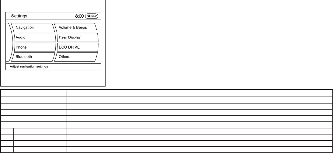
HOW TO USE THE SETTING
BUTTON
Press the SETTING button. This screen displays
and adjusts various settings and functions that
are available for your vehicle. When the amber
indicator next to an item is illuminated, the feature
is enabled.
Menu Item Result
Navigation See the separate Navigation System Owner’s Manual for more information.
Audio See “Audio system” in this section for more information.
Phone See “Bluetooth Hands-Free Phone System with Navigation System” in this section.
Bluetooth See “Bluetooth Hands-Free Phone System with Navigation System” in this section.
Volume & Beeps Adjusts the volume and beep settings.
Navigation volume See the separate Navigation System Owner’s Manual for more information.
Phone Volume See “Bluetooth Hands-Free Phone System with Navigation System” in this section.
Infiniti Connection Volume See “Infiniti Connection” in this section
Switch Beeps Toggles on or off the beep sound that is heard when a control panel button is pressed.
LHA2152
4-18 Monitor, climate, audio, phone and voice recognition systems

Menu Item Result
Rear display settings To control the rear display settings, select the “Display Control” key. Select the “ON” key for either the left or right display to alternately enable or
disable the display fo the left or right rear passengers. If the display is enabled, select the key (DVD, USB, front AUX or rear AUX) that you wish
to have displayed on the corresponding screen. The front AUX setting is for devices plugged into the AUX jacks in the center console. The rear
AUX setting is for the devices plugged into the AUX jacks on the back of the center console.
Select the “Auto Display” to set the rear displays to always on when a movie is played from a DVD or USB device.
ECO DRIVE settings (if so
equipped)
To adjust the Eco pedal driver’s assist, select the “Standard”, “Soft” or “OFF” key and adjust it with the INFINITI controller. For more information
about ECO DRIVE system,see “ECO pedal system” in the “Starting and driving” section.
Others Select the “Others” key using the INFINITI controller. The voice recognition, language and units setting screen will be displayed.
Display Adjusts the settings for the display screen
Display Adjustment To adjust the display settins, select the “Display Adjustment” key. The following settings are available:
Brightness/
Contrast
Adjusts the brightness or contrast of the map background.
Display off Toggles the display screen on and off. The amber indicator is illuminated when the display is set to “On”. When the display is set to “Off” and a
control panel, audio or heater and air conditioner button is pressed, the display will resume until that operation is finished. To turn the display back
on, press and hold the OFF button for approximately 2 seconds or return to the display setting screen and adjust the setting.
Background
Color
Adjusts the display screen between day and night mode.
Color Theme Changes the color of the background, arrows and bars on the screen. Choose between “Black”. “Brown”, or “Silver”.
Monitor, climate, audio, phone and voice recognition systems 4-19

Comfort Settings
Item Result
Comfort Select the “Comfort” key by using the INFINITI controller. The comfort option screen will be displayed. The items below will be available to adjust.
You can set the following operating conditions by highlighting the desired item using the INFINITI controller. The amber indicator (box at the right of
the selected item) alternately turns on and off each time the ENTER button is pressed.
Lift Steering Wheel
on Exit
Select to turn on or turn off the steering wheel moving upward for easy exit when the ignition switch is in the OFF position and the driver’s door is
opened. After getting into the vehicle and pushing the ignition switch to the ACC position, the steering wheel moves to the previous position.
Slide Driver Seat
Back on Exit
Select to turn on or turn off the driver’s seat moving backward for easy exit when the ignition switch is in the OFF position and the driver’s door is
opened. After getting into the vehicle and pushing the ignition switch to the ACC position, the driver’s seat moves to the previous position
Return All Settings to
Default
Select to change all the comfort and convenience systems to their default settings.
Item Result
Clock Select the SETTING button, the select the “Clock” key using the INFINITI controller to adjust the clock settings.
On-screen Clock When this item is enable (indicator light illuminated), a clock is always displayed in the upper right corner of the screen. This clock will indicate the
time almost exactly because it is always adjusted by the GPS system.
Clock Format (24h) When this item is enable (indicator light illuminated), the clock format will change from the default 12–hour display to a 24–hour display.
Offset (hour) Adjust the time by increasing or decreasing the hours.
Offset (minute) Adjust the time by increasing or decreasing the minutes.
Daylight Savings
Time
When this item is enabled (indicator light illuminated), daylight savings time is on. To turn off the daylight savings time, touch the “ON” key; the am-
ber indicator light will go out.
Time Zone Adjust the time zone. Choose a time from the available list on the display.
4-20 Monitor, climate, audio, phone and voice recognition systems

Language/Units
Use the INFINITI controller to select the
“Language/Units” key.
Item Result
Language/Units Select which settings you want to change using the INFINITI controller.
Select Language Select the “English” key, the “Français” key or the “Español” key to change the language shown on the display.
Select Units Select the “US” (mi, °F, MPG) key or the “Metric” (km, °C, L/100 km) key to change the units shown on the display.
Voice Recognition For Voice Recognition settings, refer to the “INFINITI Voice Recognition system” in this section.
Camera settings Select the “Camera” key. The Camera settings screen will appear. When this option is on (indicator light illuminated), predictive course lines
will be displayed when the RearView monitor is displayed on the screen. See “RearView Monitor” in this section for more information.
Image viewer settings For information about these settings, refer to “Image Viewer” in this section.
OFF BUTTON
To change the display brightness, press
the OFF button. Pressing the button again
will change the display to the day or the
night display. The brightness can then be
adjusted using the INFINITI controller.
If no operation is performed within 5 seconds, the
display will return to the previous display.
Press and hold the OFF button for more
than two seconds to turn the display off. Press
the button again to turn the display on.
Monitor, climate, audio, phone and voice recognition systems 4-21

USING THE IMAGE VIEWER
When a compatible portable storage device is
plugged into the USB jack located in the center
console, compatible image files stored on the
device can be viewed on the control panel de-
vice.
Connecting the portable storage
device
To connect a portable storage device to the sys-
tem so that images stored on it can be viewed,
insert the device into the USB jack located in the
center console.
Viewing images
To view an image, press the SETTING button and
then select the “Image Viewer” key with the
INFINITI controller. The Image Viewer screen will
be displayed.
A list of compatible images on the storage device
is displayed on the left side of the screen, while
the selected image is displayed on the right side
of the screen. To choose a different picture from
the list, use the INFINITI controller to scroll
through the list once the desired image is high-
lighted.
Select the “Full Screen Display” key and press
the ENTER button to view a full screen version of
the image.
Image requirements:
●Image type: JPEG
●File extensions: *.jpg, *.jpeg
●Maximum resolution: 2048 x 1536
●Maximum size: 2 MB
●Colors: 32,768 (15-bit)
●Maximum file name length: 253 bytes (dis-
play only shows first 8 characters)
●Maximum folders: 500
●Maximum images per folder: 1024
LHA1309
IMAGE VIEWER (if so equipped)
4-22 Monitor, climate, audio, phone and voice recognition systems

Viewing images in a slideshow
To view all of the images on the device in a
slideshow, first enter the full screen mode while
viewing one of the images. The slideshow control
buttons are located on the right side of the
screen.
Select the play key to begin the slideshow.
The images shown on the screen will periodically
change at a given interval of time. To skip through
the images without waiting for them to change
automatically, select the key to skip back-
ward or the key to skip forward. Select the
stop key to end the slideshow and return
to the full screen display of the image currently on
the screen.
Slideshow settings
While in slideshow mode, the following settings can be accessed:
Settings
Slideshow Speed Changes the frequency at which images are changed during a slideshow. Choose one of the options on the screen or “No Auto Change” to
have the images not change automatically.
Slideshow Order
Random Changes images in a random order when selected.
Order List Changes images in the order in which they are saved on the USB device.
LHA1310
Monitor, climate, audio, phone and voice recognition systems 4-23
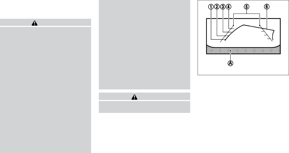
When the shift lever is shifted into the R (Re-
verse) position, the monitor display shows a rear-
ward view from the vehicle.
WARNING
●The system is designed as an aid to the
driver in situations such as slot parking
or parallel parking.
●The RearView Monitor is a convenience
but not a substitute for proper backing
procedures. Always turn to check what
is behind you before backing up.
●The RearView Monitor cannot com-
pletely eliminate blind spots or warn of
moving objects.
●The driver is always responsible for
safety during parking and other
maneuvers.
●Objects viewed in the RearView Moni-
tor differ from actual distance because
a wide-angle lens is used.
●Make sure that the liftgate is securely
closed when backing up.
●Underneath the bumper and the corner
areas of the bumper cannot be viewed
on the RearView Monitor because of its
monitoring range limitation.
●Do not put anything on the rear view
camera. The rear view camera is in-
stalled above the license plate.
●When washing the vehicle with high-
pressure water, be sure not to spray it
around the camera. Otherwise, water
may enter the camera unit causing wa-
ter condensation on the lens, a mal-
function, fire or an electric shock.
●Do not strike the camera. It is a preci-
sion instrument. Otherwise, it may mal-
function or cause damage resulting in a
fire or an electric shock.
●Objects in the rearview will appear visu-
ally opposite than when viewed in the
rearview and outside mirrors.
CAUTION
Do not scratch the camera lens when
cleaning dirt or snow from the lens.
HOW TO READ THE DISPLAYED
LINES
Guiding lines which indicate the vehicle width
and distances to objects with reference to the
vehicle body line 䊊
Aare displayed on the monitor.
Distance guide lines:
Indicate distances from the vehicle body.
●Red line 䊊
1: approx. 1.5 ft (0.5 m)
●Yellow line 䊊
2: approx. 3 ft (1 m)
●Green line 䊊
3: approx. 7 ft (2 m)
●Green line 䊊
4: approx. 10 ft (3 m)
LHA1196
REARVIEW MONITOR (if so
equipped)
4-24 Monitor, climate, audio, phone and voice recognition systems

Vehicle width guide lines 䊊
5:
Indicate the vehicle width when backing up.
Predicted course lines 䊊
6:
Indicate the predicted course when backing up.
The predicted course lines will be displayed on
the monitor when the shift selector is in the R
(Reverse) position and the steering wheel is
turned. The predicted course lines will move de-
pending on how much the steering wheel is
turned and will not be displayed while the steer-
ing wheel is in the neutral position.
The vehicle width guide lines and the width of the
predicted course lines are wider than the actual
width and course.
WARNING
●Always turn and check that it is safe to
do so before backing up. Always back
up slowly.
●If the tires are replaced with different
sized tires, the predicted course lines
may be displayed incorrectly.
●On a snow-covered or slippery road,
there may be a difference between the
predicted course line and the actual
course line.
●The distance guide line and the vehicle
width line and predicted course lines
should be used as a reference only
when the vehicle is on a level paved
surface. The distance viewed on the
monitor is for reference only and may
be different than the actual distance
between the vehicle and displayed
objects.
●When backing up the vehicle up a hill,
objects viewed in the monitor are fur-
ther than they appear. When backing up
the vehicle down a hill, objects viewed
in the monitor are closer than they ap-
pear. Use the inside mirror or glance
over your shoulder to properly judge
distances to other objects.
HOW TO PARK WITH PREDICTED
COURSE LINES
1. Visually check that the parking space is safe
before parking your vehicle.
2. The rear view of the vehicle is displayed on
the screen 䊊
Awhen the shift lever is moved
to the R (Reverse) position.
LHA1197
Monitor, climate, audio, phone and voice recognition systems 4-25

3. Slowly back up the vehicle adjusting the
steering wheel so that the predicted course
lines 䊊
Benter the parking space 䊊
C.
4. When the back of the vehicle enters the
parking space 䊊
C, maneuver the steering
wheel to make the vehicle width guide lines
䊊
Dparallel to the parking spaces 䊊
C.
5. When the vehicle is parked in the space
completely, move the shift lever to the P
(Park) position and apply the parking brake.
DIFFERENCE BETWEEN
PREDICTIVE AND ACTUAL
DISTANCES
LHA1198 LHA1199
4-26 Monitor, climate, audio, phone and voice recognition systems

displayed. It will be shown only the first time after
the ignition switch is placed in the ON position.
When the corner of the vehicle moves closer to
an object, the corner sonar indicators 䊊
3appear.
When the center of the vehicle moves close to an
object, the center sonar indicator 䊊
4appears (if
so equipped).
The driver can check the direction and angle of
the tire on the display by tire icon 䊊
5when driving
the vehicle forward or backward.
Predictive course lines (䊊
6and 䊊
7) indicate the
predictive course when operating the vehicle.
The predictive course lines will be displayed on
the monitor when the steering wheel is turned.
The predictive course lines will move depending
on how much the steering wheel is turned and
will not be displayed while the steering wheel is in
the neutral position.
When the monitor displays the front view and the
steering wheel turns about 90 degrees or less
from the neutral position, the two green predic-
tive course lines 䊊
6are shown in front of the
vehicle.
When the steering wheel turns about 90 degrees
or more, one green predictive course lines is
shown in front of the vehicle and other green
predictive course lines 䊊
7is shown at side of the
vehicle.
When the monitor displays the rear view, the
predictive course lines are shown at back of the
vehicle.
WARNING
●Objects in the bird’s-eye view will ap-
pear further than the actual distance
because the bird’s-eye view is a pseudo
view that is processed by combining the
views from the cameras on the outside
mirrors, the front and the rear of the
vehicle.
●Tall objects, such as a curb or vehicle,
may be misaligned or not displayed at
the seam of the views.
●Objects that are above the camera can-
not be displayed.
●The view of the bird’s-eye view may be
misaligned when the camera position
alters.
●A line on the ground may be misaligned
and is not seen as being straight at the
seam of the views. The misalignment
will increase as the line proceeds away
from the vehicle.
●Tire angle display does not indicate the
actual tire angle.
Front-side view
Guiding lines:
Guiding lines that indicate the width and the front
end of the vehicle are displayed on the monitor.
The front-of-vehicle line 䊊
1shows the front part
of the vehicle.
The side-of-vehicle line 䊊
2shows the vehicle
width including the outside mirrors.
The extensions 䊊
3of both the front 䊊
1and side
䊊
2lines are shown with a green dotted line.
The corner sonar indicator 䊊
4will appear when a
corner of the vehicle moves closer to an object.
SAA1842
Monitor, climate, audio, phone and voice recognition systems 4-33
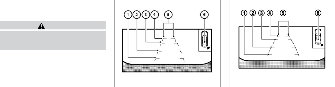
The corner sonar indicator 䊊
4can be turned off.
See “Around View Monitor settings” in this sec-
tion.
CAUTION
The turn signal light may look like the
side-of-vehicle line. This is not a
malfunction.
Front-wide and rear-wide view
The front-wide and rear-wide view shows a wider
area on the entire screen and allows the checking
of the blind corners on right and left sides. The
rear-wide view displays an approximately 180-
degree area while the front-view and rearview
display an approximately 150-degree area. The
predictive course lines are not displayed when
using the front-wide and rear-wide view.
Distance guide lines:
Indicates distances from the vehicle body:
●Red line 䊊
1: approximately 1.5 ft (0.5 m)
●Yellow line 䊊
2: approximately 3 ft (1 m)
●Green line 䊊
3: approximately 7 ft (2 m)
●Green line 䊊
4: approximately 10 ft (3 m)
Vehicle width guide lines 䊊
5:
Indicate the vehicle width when backing up.
The corner sonar indicator 䊊
6will appear when a
corner of the vehicle moves closer to an object.
Front-wide view
LHA2318
Rear-wide view
SAA2629
4-34 Monitor, climate, audio, phone and voice recognition systems

DIFFERENCE BETWEEN
PREDICTIVE AND ACTUAL
DISTANCES
Backing up on a steep uphill
When backing up the vehicle up a hill, the dis-
tance guide lines and the vehicle width guide
lines are shown closer than the actual distance.
For example, the display shows 3 ft (1.0 m) to the
place 䊊
A, but the actual 3 ft (1.0 m) distance on
the hill is the place 䊊
B. Note that any object on
the hill is further than it appears on the monitor.
LHA1199
Monitor, climate, audio, phone and voice recognition systems 4-35

Backing up on a steep downhill
When backing up the vehicle down a hill, the
distance guide lines and the vehicle width guide
lines are shown farther than the actual distance.
For example, the display shows 3 ft (1.0 m) to the
place 䊊
A, but the actual 3 ft (1.0 m) distance on
the hill is the place 䊊
B. Note that any object on
the hill is closer than it appears on the monitor.
Backing up near a projecting object
The predicted course lines 䊊
Ado not touch the
object in the display. However, the vehicle may hit
the object if it projects over the actual backing up
course.
LHA1200 LHA1201
4-36 Monitor, climate, audio, phone and voice recognition systems

Backing up behind a projecting object
The position 䊊
Cis shown farther than the position
䊊
Bin the display. However, the position 䊊
Cis
actually at the same distance as the position 䊊
A.
The vehicle may hit the object when backing up to
the position 䊊
Aif the object projects over the
actual backing up course.
HOW TO SWITCH THE DISPLAY
With the ignition switch in the ON position, press
the CAMERA button or move the shift lever to the
R (Reverse) position to operate the Around View
Monitor.
The Around View Monitor can display two split
views as well as a single view of the front-wide
view or rear-wide view. Select the “Change View”
key to switch between the available views.
LHA1202
LHA2319
Monitor, climate, audio, phone and voice recognition systems 4-37

If the shift lever is not in the R (Reverse) position,
the available views are:
●Front-view/bird’s-eye view split screen
●Front-view/front-side view split screen
●Front-wide view
If the shift lever is in the R (Reverse) position, the
available views are:
●Rearview/bird’s-eye view split screen
●Rearview/front-side view split screen
●Rear-wide view
The display automatically changes to the Around
View Monitor displaying front-view/bird’s-eye
view when:
●The shift lever is in the D (Drive) position and
the sonar detects the vehicle is approaching
an object.
The display will switch from the Around View
Monitor screen when:
●When the shift lever is in the D (Drive) posi-
tion and the vehicle speed increases above
approximately 6 mph (10 km/h)
●When the sonar no longer detects an object
the screen will automatically switch back the
previously displayed screen.
●When a different screen is selected.
PARKING SENSOR (if so equipped)
REAR CENTER SONAR (if so
equipped)
The sonar (parking sensor) sounds a tone to
inform the driver of obstacles near the bumper.
WARNING
●The sonar (parking sensor) is a conve-
nience feature. It is not a substitute for
proper parking.
●The system is deactivated at speeds
above 6 mph (10km/h). It is reactivated
at lower speeds.
●The driver is always responsible for
safety during parking and other
maneuvers.
●Always look around and check that it is
safe to move before parking.
●Read and understand the limitations of
the sonar (parking sensor) as contained
in this section.
●The colors of the sonar indicators and
the distance guide lines in the front,
front-wide, rear and rear-wide views in-
dicate different distances to the object.
●Inclement weather or ultrasonic
sources such as an automatic car wash,
a truck’s compressed-air brakes or a
pneumatic drill may affect the function
of the system; this may include reduced
performance or a false activation.
●This function is designed as an aid to
the driver in detecting large stationary
objects to help avoid damaging the
vehicle.
●The system is not designed to prevent
contact with small or moving objects.
●The system will not detect small objects
below the bumper, and may not detect
objects close to the bumper or on the
ground.
LHA2320
4-38 Monitor, climate, audio, phone and voice recognition systems
** See Owner's Manual Supplement on page 2 **
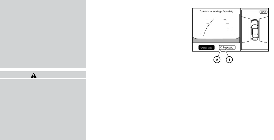
●The system may not detect the follow-
ing objects:
– Fluffy objects such as snow, cloth,
cotton, glass or wool.
– Thin objects such as rope, wire or
chain.
– Wedge-shaped objects.
●If your vehicle sustains damage to the
bumper fascia, leaving it misaligned or
bent, the sensing zone may be altered
causing inaccurate measurement of ob-
jects or false alarms.
CAUTION
●Excessive noise (such as audio system
volume or an open vehicle window) will
interfere with the tone and it may not be
heard.
●Keep the surface of the sonar sensors
(located on the front and rear bumper
fascia) free from accumulations of
snow, ice and dirt. Do not scratch the
surface of the sonar sensors when
cleaning. If the sensors are covered, the
accuracy of the sonar function will be
diminished.
The system gives the tone for front objects when
the shift lever is in the D (Drive) position and both
front and rear objects when the shift lever is in the
R (Reverse) position.
When the camera image is shown on the display,
the system shows the sonar indicator regardless
of the shift selector position.
The system is deactivated at speeds above
6 mph (10 km/h). It is reactivated at lower
speeds.
When the objects are detected, the indicator
(green) appears and blinks and the tone sounds
intermittently. When the vehicle moves closer to
the object, the color of the indicator turns yellow
and the rate of the blinking and the rate of the
tone increase. When the vehicle is very close to
the object, the indicator stops blinking and turns
red, and the tone sounds continuously.
The intermittent tone will stop after three seconds
when an object is detected by only the corner
sonar and the distance does not change.
The tone will stop when the object is no longer
near the vehicle.
When the key 䊊
1is selected, the indicator 䊊
2will
turn off and the sonar will be turned off temporar-
ily. The MOD system will also be turned off at the
same time. When the key is selected again, the
indicator will turn on and the sonar will turn back
on.
In the below cases, the sonar will be turned back
on automatically:
●When the shift lever is in the R (Reverse)
position.
●When the CAMERA button is pressed and a
screen other than the camera view is shown
on the display.
LHA2321
Monitor, climate, audio, phone and voice recognition systems 4-39

●When vehicle speed decreases below ap-
proximately 6 mph (10 km/h).
●When the ignition switch is placed in the
OFF position and turned back to the ON
position again.
To prevent the sonar system from activating alto-
gether, use the “Camera Settings” menu. For
more information, see “Around View® Monitor
settings” in this section.
MOVING OBJECT DETECTION
(MOD)
The Moving Object Detection (MOD) system can
inform the driver of the moving objects surround-
ing the vehicle when driving out of garages, ma-
neuvering into parking lots and in other such
instances.
The MOD system detects moving objects by
using image processing technology on the image
shown in the display.
The MOD system operates in the following con-
ditions when the camera view is displayed:
●When the shift lever is in the P or N position
and the vehicle is stopped, the MOD system
detects the moving objects in the bird’s-eye
view. The MOD system will not operate if the
outside mirror is moving in or out or if either
door is opened.
●When the shift lever is in the D position and
the vehicle speed is below approximately
5 mph (8 km/h), the MOD system detects
moving objects in the front view or front-
wide view.
●When the shift lever is in the R position and
the vehicle speed is below approximately
5 mph (8 km/h), the MOD system detects
moving objects in the rearview or rear-wide
view. The MOD system will not operate if the
liftgate is open.
The MOD system does not detect moving ob-
jects in the front-side view. The MOD icon is not
displayed on the screen when in this view.
WARNING
●The MOD system is not a substitute for
proper vehicle operation and is not de-
signed to prevent contact with the ob-
jects surrounding the vehicle. When
maneuvering, always use the outside
mirror and rear view mirror and turn and
check the surrounding to ensure it is
safe to maneuver.
●The system is deactivated at speeds
above 6 mph (10 km/h). It is reactivated
at lower speeds
●The system is not designed to prevent
contact with all objects.
●The MOD system does not have the
function to detect the surrounding sta-
tionary objects.
4-40 Monitor, climate, audio, phone and voice recognition systems

When the MOD system detects moving objects
surrounding the vehicle, the yellow frame will be
displayed on the view where the objects are
detected and a chime will sound once. While the
MOD system continues to detect moving ob-
jects, the yellow frame continues to be displayed.
In the bird’s-eye view, the yellow frame 䊊
1is
displayed on each camera image (front, rear,
right, left) depending on where moving objects
are detected.
The yellow frame 䊊
2is displayed on each view in
the front view, front-wide view, rear view and
rear-wide view modes.
While the sonar or the BCI chime (if so equipped)
is beeping, the MOD system does not chime.
A blue MOD icon is displayed in the view where
the MOD system is operative. A gray MOD icon is
displayed in the view where the MOD system is
not operative.
When the “MOD” key 䊊
4is selected, the MOD
system will turn off temporarily and the indicator
䊊
5will turn off. At the same time the camera-
aiding sonar will also be turned OFF. When the
key is pressed again, the indicator will turn on and
the MOD system will turn back on.
If the MOD system is turned off, the MOD icon 䊊
3
is not displayed.
The MOD system will turn on automatically under
the following conditions:
●When the shift lever is in the R position.
●When the CAMERA button is pressed to
switch from a different screen to the camera
view on the display
●When vehicle speed decreases below ap-
proximately 5 mph (8 km/h).
●When the ignition switch is placed in the
OFF position and then back to the ON posi-
tion.
LHA2322
Monitor, climate, audio, phone and voice recognition systems 4-41

To set the MOD system so that it remains off at all
times, use the camera settings menu. See
“Around View Monitor settings” in this section for
more information.
WARNING
●Do not use the MOD system when tow-
ing a trailer. The system may not func-
tion properly.
●Excessive noise (for example, audio
system volume or open vehicle window)
will interfere with the chime sound, and
it may not be heard.
●The MOD system performance will be
limited according to environmental con-
ditions and surrounding objects such
as:
– When there is low contrast between
background and the moving objects.
– When there is blinking source of
light.
– When strong light such as another
vehicle’s headlight or sunlight is
present.
– When camera orientation is not in its
usual position, such as when mirror
is folded.
– When there is dirt, water drops or
snow on the camera lens.
– When the position of the moving ob-
jects in the display is not changed.
●The MOD system might detect flowing
water droplets on the camera lens,
white smoke from the muffler, moving
shadows, etc.
●The MOD system may not function
properly depending on the speed, direc-
tion, distance or shape of the moving
objects.
●If your vehicle sustains damage to the
parts where the camera is installed,
leaving it misaligned or bent, the sens-
ing zone may be altered and the MOD
system may not detect objects properly.
●When the temperature is extremly high
or low, the screen may not display ob-
jects clearly. This is not a malfunction.
Camera maintenance
If dirt, rain or snow accumulates on the camera,
the MOD system may not operate properly. Clean
the camera.
HOW TO ADJUST THE SCREEN
VIEW
To adjust the Display ON/OFF, Brightness, Tint,
Color, Contrast and Black Level of the Around
View Monitor, press the SETTING button with the
Around View Monitor on, select the item key and
adjust the level using the INFINITI controller.
Do not adjust the Brightness, Tint, Color, Con-
trast and Black Level of the Around View Monitor
while the vehicle is moving. Make sure the park-
ing brake is firmly applied.
4-42 Monitor, climate, audio, phone and voice recognition systems
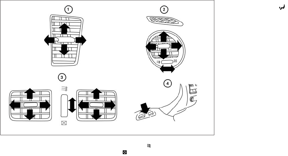
Adjust air flow direction for the center vents 䊊
1,
driver’s and passenger’s side vents 䊊
2, and rear
vents 䊊
3by moving the vent slide and/or vent
assemblies.
Open or close the vents using the dial. Move the
dial toward the to open the vents or toward
the to close them.
The vents underneath the second row seats 䊊
4
are operational when the air flow mode is
selected. These vents cannot be closed. See “Air
flow control” in this section for more information.
LHA2324
VENTS
4-46 Monitor, climate, audio, phone and voice recognition systems

1. (front defroster) button
2. (rear window defroster) button
3. OFF button
4. Fan speed decrease button
5. Fan speed increase button
6. AUTO climate control ON button
7. REAR button
8. Air recirculation button
9. CLIMATE button
10. Temperature control (increase) button
(driver’s side)
11. Temperature control (decrease) button
(driver’s side)
12. Manual air flow control button
(driver’s side)
13. DUAL button
14. Temperature control (decrease) button
(passenger’s side)
15. Temperature control (increase) button
(passenger’s side)
WARNING
●The air conditioner cooling function op-
erates only when the engine is running.
●Do not leave children or adults who
would normally require the assistance
of others alone in your vehicle. Pets
should also not be left alone. They
could accidentally injure themselves or
others through inadvertent operation of
the vehicle. Also, on hot, sunny days,
temperatures in a closed vehicle could
quickly become high enough to cause
severe or possibly fatal injuries to
people or animals.
●Do not use the recirculation mode for
long periods as it may cause the interior
air to become stale and the windows to
fog up.
LHA2133
HEATER AND AIR CONDITIONER
(automatic)
Monitor, climate, audio, phone and voice recognition systems 4-47

Start the engine and operate the controls to
activate the air conditioner.
●Odors from inside and outside the vehicle
can build up in the air conditioner unit. Odor
can enter the passenger compartment
through the vents.
●When parking, set the heater and air condi-
tioner controls to turn off air recirculation to
allow fresh air into the passenger compart-
ment. This should help reduce odors inside
the vehicle.
AUTOMATIC OPERATION
Cooling and/or dehumidified heating
(AUTO)
This mode may be used all year round as the
system automatically works to keep a constant
temperature. Air flow distribution, intake air con-
trol, and fan speed are also controlled automati-
cally.
1. Press the AUTO button on. (The indicator on
the button will illuminate and AUTO will be
displayed.)
2. Operate the driver’s side temperature con-
trol buttons.
●Adjust the temperature display to about
75°F (24°C) for normal operation.
●The temperature of the passenger compart-
ment will be maintained automatically. Air
flow distribution, intake air control, and fan
speed are also controlled automatically.
●A visible mist may be seen coming from the
ventilators in hot, humid conditions as the air
is cooled rapidly. This does not indicate a
malfunction.
Dehumidified defrosting or defogging
1. Press the front defroster button on.
(The indicator light on the button will come
on.)
2. Operate the temperature control buttons to
set the desired temperature.
●To quickly remove ice from the outside of the
windows, use the fan speed control dial to
set the fan speed to maximum.
●As soon as possible after the windshield is
clean, press the AUTO button to return to
the automatic mode.
●When the front defroster button is
pressed, the air conditioner will automati-
cally be turned on at outside temperatures
above 36°F (2°C). The air recirculate mode
automatically turns off, allowing outside air
to be drawn into the passenger compart-
ment to further improve the defogging per-
formance.
MANUAL OPERATION
Fan speed control
Press the fan control buttons to manually
control the fan speed.
Press the AUTO button to return to automatic
control of the fan speed.
Temperature control
Press the temperature control buttons up or
down to set the desired temperature.
The temperature can be set within the following
range:
●For U.S.: 60 to 90ºF (16 to 32ºC)
●For Canada: 64 to 90ºF (18 to 32ºC)
4-48 Monitor, climate, audio, phone and voice recognition systems

Air recirculation
Press the air recirculation button to recir-
culate interior air inside the vehicle. The
indicator light on the button will come on.
The air recirculation cannot be activated when
the air conditioner is in the front defrosting
mode or the front defrosting and foot out-
let mode.
Automatic intake air control
In the AUTO mode, the intake air will be con-
trolled automatically. To manually control the in-
take air, press the air recirculation button.
To return to the automatic control mode, press
and hold the air recirculation button for
about 2 seconds. The indicator light will flash
twice, and then the intake air will be controlled
automatically.
Air flow control
Press the button to manually control air
flow. Pressing the button repeatedly will cycle
through the available modes and display the cor-
responding icon on the center display:
— Air flows from center and side
vents.
— Air flows from center and side
vents and foot outlets.
— Air flows mainly from foot outlets.
— Air flows from defroster and foot
outlets.
— Air flows from defroster outlets.
To turn system off
Press the OFF button.
OPERATING TIPS
●When the engine coolant temperature and
outside air temperature are low, the air flow
from the foot outlets may not operate for a
maximum of 150 seconds. However, this is
not a malfunction. After the coolant tempera-
ture warms up, air flow from the foot outlets
will operate normally.
The sunload sensor, located on the top driver’s
side of the instrument panel, helps the system
maintain a constant temperature. Do not put any-
thing on or around this sensor.
LHA2173
Monitor, climate, audio, phone and voice recognition systems 4-49

CLIMATE SETTING SCREEN
Climate control settings can be changed on the
screen.
Press the CLIMATE button on the instrument
panel and turn the display to the Climate mode.
Heating (A/C off)
The air conditioner does not activate in this mode.
When you need to heat only, use this mode.
1. Press the CLIMATE button.
2. If the “A/C” indicator on the screen illumi-
nates, select the “A/C” key. (The “A/C” indi-
cator will turn off.)
3. Press the temperature control button to set
the desired temperature.
●The temperature of the passenger compart-
ment will be maintained automatically. Air
flow distribution and fan speed are also con-
trolled automatically.
●Do not set the temperature lower than the
outside air temperature or the system may
not work properly.
●This procedure is not recommended if win-
dows fog up.
When the outside temperature decreases to ap-
proximately 32°F (0°C), the A/C function does
not activate even if the “A/C” indicator light illu-
minates.
Dual control mode setting
You can individually set the driver and front pas-
senger side temperature and air flow mode using
each temperature control button or manual air
flow control button.
1. Press the CLIMATE button.
2. By selecting the “DUAL” key, or when the
passenger side temperature control button
or manual air control button is pushed, the
“DUAL” indicator on the screen will illumi-
nate.
3. To turn off the passenger side temperature
control, select the “DUAL” key and the
“DUAL” indicator will turn off.
●The Dual control mode cannot be activated
when the air conditioner is in the front de-
frosting mode.
Advanced Climate Control System
(ACCS) (if so equipped)
The Advanced Climate Control System (ACCS)
keeps the air inside of the vehicle clean, using the
ion control and the automatic air intake control
with exhaust gas detecting sensor.
LHA2167
4-50 Monitor, climate, audio, phone and voice recognition systems

Ion control:
This unit generates highly concentrated Plasma-
cluster™ ions into the air blown from the vents
and reduces odor absorbed into the interior trim.
When the air conditioner is turned on, the system
generates Plasmacluster™ ions automatically.
The amount of Plasmacluster™ ions increases
according to the amount of air flow. When the air
flow is high, is displayed on the screen and
when the air flow is low, the indication in the
screen changes to .
Plasmacluster™ and Plasmacluster™ ion are reg-
istered trademarks of Sharp Corporation.
Exhaust gas/outside odor detection sen-
sor:
This vehicle is equipped with an exhaust gas
detection sensor. When the automatic intake air
control is ON, the sensor detects industry odors
such as pulp or chemicals, and exhaust gas such
as gasoline or diesel. When such odors or gas
are detected, the system automatically changes
from the outside air circulation mode to the recir-
culation mode.
When the intake air control button is pushed
under the following conditions, the indicator light
on the button will illuminate and the ex-
haust gas detection sensor will turn on.
●The air flow control is not in the front de-
froster mode (the indicator light on
the front defroster button is turned
off).
●The outside temperature is about 32°F (0°C)
or more.
When the automatic intake air control is ON, for
the first 5 minutes, the recirculation mode is
selected to prevent dust, dirt and pollen from
entering the vehicle and cleans the air inside of
the vehicle with positive and negative ions that
are emitted from the vent.
After the 5 minutes, the sensor detects exhaust
gas and automatically alternates between the
recirculation mode and outside air circulation
mode.
LHA2222
Monitor, climate, audio, phone and voice recognition systems 4-51

Rear automatic air conditioning system
To control the rear automatic air conditioning
system with the front air conditioner control
panel, press the REAR button. When the rear
automatic air conditioning system control is on,
the indicator light on the REAR button will illumi-
nate and the front display will switch to the rear air
conditioner screen.
The rear automatic air conditioning system can
be adjusted with the front air conditioner control
panel, when the rear air conditioner screen is
displayed.
To adjust the front air conditioning system, press
the REAR button one more time.
Automatic operation:
1. Press the AUTO button. The AUTO indicator
light will illuminate and “AUTO” will appear
on the display.
2. Turn the temperature control dial (driver’s
side) to set the desired temperature.
Manual operation :
●Temperature control
Press the temperature control buttons to set
the desired temperature.
●Fan speed control
Press the fan speed increase or decrease
button to manually control the fan speed.
Press the OFF button when the rear automatic air
conditioning system is turned on with the rear air
conditioner screen displayed to turn off the rear
automatic air conditioning system.
Rear Heating (A/C off):
1. Press the REAR button to display the rear air
conditioner screen on the front display when
the rear automatic air conditioning system is
on.
2. Press the AUTO button. The AUTO indicator
light will illuminate and “AUTO” will appear
on the display.
3. If the A/C indicator light illuminates, press
the A/C button. The A/C indicator light will
turn off.
4. Turn the temperature control dial to set the
desired temperature.
●Do not set the temperature lower than the
outside air temperature. Doing so may cause
the temperature to not be controlled prop-
erly.
●To dehumidify the air, press the A/C key
before turning on the heater.
Turning the system off :
Press the OFF button when the rear air condi-
tioner screen is displayed.
LHA2168
4-52 Monitor, climate, audio, phone and voice recognition systems
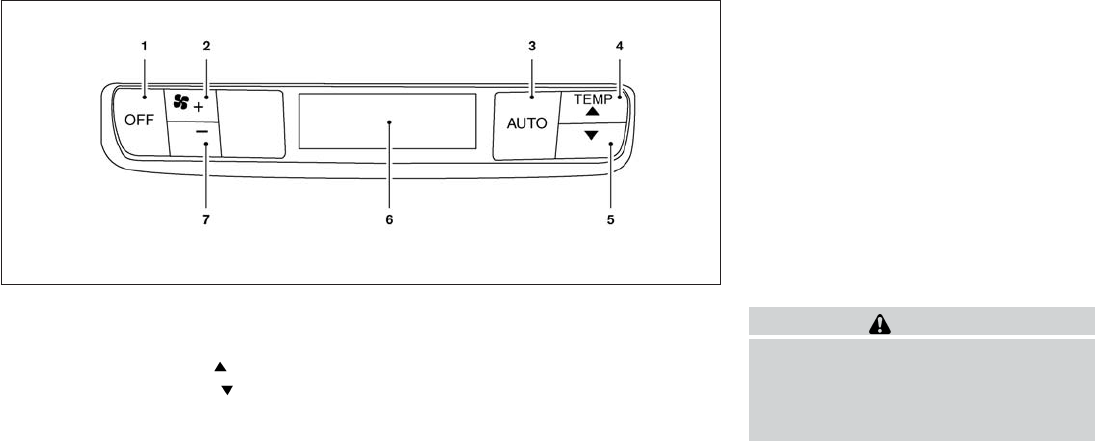
1. OFF button
2. Fan speed increase (+) button
3. AUTO button
4. Temperature increase ( ) button
5. Temperature decrease ( ) button
6. Display
7. Fan speed decrease (-) button
Rear control buttons:
The rear seat passengers can adjust the rear
automatic air conditioning system using the con-
trol switches at the rear of the center console.
The rear control buttons do not function when the
rear air conditioner screen is shown on the front
display. To activate the rear control buttons,
press the REAR button on the front air condi-
tioner control panel and switch the screen on the
front display.
OFF button: Turns rear automatic air conditioning
system off.
Fan speed increase and decrease buttons: Ad-
justs the rear fan speed up or down.
AUTO button: Turns rear automatic air condition-
ing system on, AUTO mode on.
Temperature increase and decrease buttons: Ad-
justs the rear temperature up or down
The air conditioner system in your INFINITI ve-
hicle is charged with a refrigerant designed with
the environment in mind.
This refrigerant does not harm the earth’s
ozone layer.
Special charging equipment and lubricant is re-
quired when servicing your INFINITI air condi-
tioner. Using improper refrigerants or lubricants
will cause severe damage to your air conditioner
system. See “Air conditioner system refrigerant
and oil recommendations” in the “Technical and
consumer information” section of this manual.
An INFINITI retailer is able to service your “envi-
ronmentally friendly” air conditioning system.
WARNING
The air conditioner system contains refrig-
erant under high pressure. To avoid per-
sonal injury, any air conditioner service
should be done only by an experienced
technician with proper equipment.
LHA2134
SERVICING AIR CONDITIONER
Monitor, climate, audio, phone and voice recognition systems 4-53
RADIO
Place the ignition switch in the ACC or ON
position and press the VOL (volume)/ON·OFF
(power) knob to turn the radio on. If you listen to
the radio with the engine not running, the ignition
switch should be placed in the ACC position.
Radio reception is affected by station signal
strength, distance from radio transmitter, build-
ings, bridges, mountains and other external influ-
ences. Intermittent changes in reception quality
normally are caused by these external influences.
Using a cellular phone in or near the vehicle
may influence radio reception quality.
Radio reception
Your INFINITI radio system is equipped with
state-of-the-art electronic circuits to enhance ra-
dio reception. These circuits are designed to
extend reception range, and to enhance the qual-
ity of that reception.
However, there are some general characteristics
of both FM and AM radio signals that can affect
radio reception quality in a moving vehicle, even
when the finest equipment is used. These char-
acteristics are completely normal in a given re-
ception area, and do not indicate any malfunction
in your INFINITI radio system.
Reception conditions will constantly change be-
cause of vehicle movement. Buildings, terrain,
signal distance and interference from other ve-
hicles can work against ideal reception. De-
scribed below are some of the factors that can
affect your radio reception.
Some cellular phones or other devices may
cause interference or a buzzing noise to come
from the audio system speakers. Storing the de-
vice in a different location may reduce or elimi-
nate the noise.
FM RADIO RECEPTION
Range: FM range is normally limited to 25 – 30 mi
(40 – 48 km), with monaural (single channel) FM
having slightly more range than stereo FM. Exter-
nal influences may sometimes interfere with FM
station reception even if the FM station is within
25 mi (40 km). The strength of the FM signal is
directly related to the distance between the
transmitter and receiver. FM signals follow a line-
of-sight path, exhibiting many of the same char-
acteristics as light. For example, they will reflect
off objects.
Fade and drift: As your vehicle moves away from
a station transmitter, the signals will tend to fade
and/or drift.
Static and flutter: During signal interference from
buildings, large hills or due to antenna position
(usually in conjunction with increased distance
from the station transmitter), static or flutter can
be heard. This can be reduced by adjusting the
treble control to reduce treble response.
Multipath reception: Because of the reflective
characteristics of FM signals, direct and reflected
signals reach the receiver at the same time. The
signals may cancel each other, resulting in mo-
mentary flutter or loss of sound.
AM RADIO RECEPTION
AM signals, because of their low frequency, can
bend around objects and skip along the ground.
In addition, the signals can be bounced off the
ionosphere and bent back to earth. Because of
these characteristics, AM signals are also sub-
ject to interference as they travel from transmitter
to receiver.
Fading: Occurs while the vehicle is passing
through freeway underpasses or in areas with
many tall buildings. It can also occur for several
seconds during ionospheric turbulence even in
areas where no obstacles exist.
Static: Caused by thunderstorms, electrical
power lines, electric signs and even traffic lights.
AUDIO SYSTEM
4-54 Monitor, climate, audio, phone and voice recognition systems
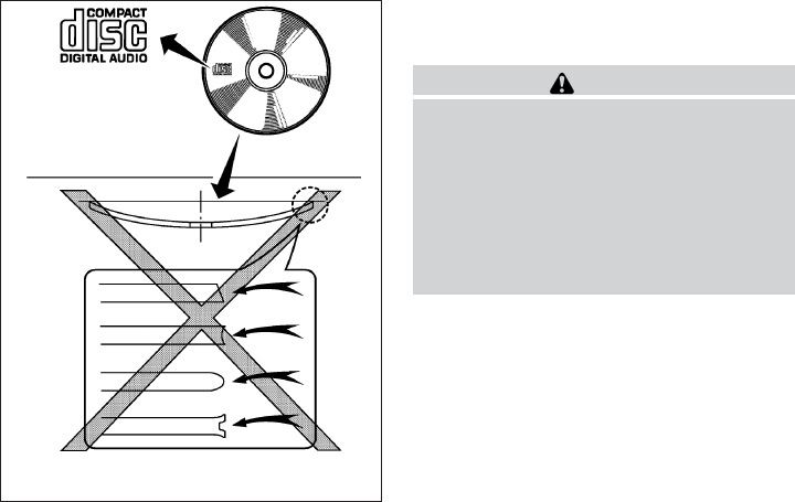
SATELLITE RADIO RECEPTION (if so
equipped)
When the satellite radio is used for the first time
or the battery has been replaced, the satellite
radio may not work properly. This is not a mal-
function. Wait more than 10 minutes with satellite
radio ON and the vehicle outside of any metal or
large building for satellite radio to receive all of
the necessary data.
The satellite radio mode will be skipped unless an
optional satellite receiver and antenna are in-
stalled and a SiriusXM Satellite Radio service
subscription is active. Satellite radio is not avail-
able in Alaska, Hawaii and Guam.
Satellite radio performance may be affected if
cargo carried on the roof blocks the satellite radio
signal.
If possible, do not put cargo over the satellite
antenna.
A build up of ice on the satellite radio antenna can
affect satellite radio performance. Remove the
ice to restore satellite radio reception.
XM® is a registered trademark of SiriusXM Sat-
ellite Radio, Inc.
AUDIO OPERATION PRECAUTIONS
Compact disc (CD) player (models
without Navigation System)
CAUTION
●Do not force a compact disc into the CD
insert slot. This could damage the CD
and/or CD changer/player.
●Trying to load a CD with the CD door
closed could damage the CD and/or CD
changer.
●Only one CD can be loaded into the CD
player at a time.
●Only use high quality 4.7 in (12 cm)
round discs that have the “COMPACT
disc DIGITAL AUDIO” logo on the disc
or packaging.
●During cold weather or rainy days, the
player may malfunction due to the hu-
midity. If this occurs, remove the CD
and dehumidify or ventilate the player
completely.
●The player may skip while driving on
rough roads.
LHA0099
Monitor, climate, audio, phone and voice recognition systems 4-55
●The CD player sometimes cannot func-
tion when the compartment tempera-
ture is extremely high or low.
Decrease/increase the temperature
before use.
●Do not expose the CD to direct sun-
light.
●CDs that are in poor condition or are
dirty, scratched or covered with finger-
prints may not work properly.
●The following CDs may not work prop-
erly:
●Copy control compact discs (CCCD)
●Recordable compact discs (CD-R)
●Rewritable compact discs (CD-RW)
●Do not use the following CDs as they
may cause the CD player to malfunc-
tion:
●3.1 in (8 cm) discs with an adapter
●CDs that are not round
●CDs with a paper label
●CDs that are warped, scratched, or
have abnormal edges
●This audio system can only play pre-
recorded CDs. It has no capability to
record or burn CDs.
●If the CD cannot be played, one of the
following messages will be displayed.
CHECK DISC:
●Confirm that the CD is inserted cor-
rectly (the label side is facing up,
etc.).
●Confirm that the CD is not bent or
warped and it is free of scratches.
PRESS EJECT:
This is an error due to excessive tem-
perature inside the player. Remove the
CD by pressing the EJECT button. After
a short time, reinsert the CD. The CD
can be played when the temperature of
the player returns to normal.
UNPLAYABLE:
The file is unplayable in this audio sys-
tem (only MP3 or WMA (if so equipped)
CD).
CD/DVD combination player (models
with Navigation System)
●Do not force a disc into the CD/DVD
insert slot. This could damage the
CD/DVD player.
●During cold weather or rainy days, the
player may malfunction due to the hu-
midity. If this occurs, remove the
CD/DVD and dehumidify or ventilate
the player completely.
●The player may skip while driving on
rough roads.
●The CD/DVD player sometimes cannot
function when the passenger compart-
ment temperature is extremely high.
Decrease the temperature before use.
●Only use high quality 4.7 in (12 cm)
round discs that have the “COMPACT
disc DIGITAL AUDIO” or “DVD Video”
logo on the disc or packaging.
●Do not expose the CD/DVD to direct
sunlight.
●CDs/DVDs that are of poor quality,
dirty, scratched, covered with finger-
prints, or that have pinholes may not
work properly.
4-56 Monitor, climate, audio, phone and voice recognition systems
●The following CDs/DVDs are not guar-
anteed to play:
●Copy control compact discs (CCCD)
●Recordable compact discs (CD-R)
●Rewritable compact discs (CD-RW)
●Recordable compact discs (DVD±R,
DVD±R DL)
●Rewritable compact discs
(DVD±RW, DVD±RW DL)
●Do not use the following CDs/DVDs as
they may cause the CD/DVD player to
malfunction.
●3.1 in (8 cm) discs
●CDs/DVDs that are not round
●CDs/DVDs with a paper label
●CDs/DVDs that are warped,
scratched, or have abnormal edges
●This audio system can only play pre-
recorded CDs/DVDs. It has no capa-
bilities to record or burn CDs/DVDs.
●If the CD/DVD cannot be played, one of
the following messages will be dis-
played.
Disc Read Error:
●Confirm that the CD/DVD is inserted
correctly (the label side is facing up,
etc.).
●Confirm that the CD/DVD is not bent
or warped and it is free of scratches.
Please Eject Disc:
This error may be due to the tempera-
ture inside the player getting too high.
Remove the CD/DVD by pushing the
EJECT button, and after a short time
reinsert the CD/DVD. The CD/DVD can
be played when the temperature of the
player returns to normal. If the error
persists, consult your local dealership.
Unplayable File:
●The file may be copy protected.
●The file is not MP3, WMA, AAC, M4A
or DIVX type.
Region Invalid
●The DVD is not for region 1 or all
regions.
●Use DVDs with a region code “1”,
“ALL” or “1 included” for your DVD
entertainment system. (The region
code 䊊
Ais displayed as a small sym-
bol printed on the top of the DVD
䊊
B.) This vehicle-installed DVD
player cannot play DVDs with a re-
gion code other than “1” or “ALL”.
Monitor, climate, audio, phone and voice recognition systems 4-57

Copyright and trademark
●The technology protected by the U.S.
patent and other intellectual property
rights owned by Macrovision
Corporation and other right holders is
adopted for this system.
●This copyright protected technology
cannot be used without a permit from
Macrovision Corporation. It is limited
to personal use, etc., as long as the
permit from Macrovision Corporation
is not issued.
●Modifying or disassembling is prohib-
ited.
●Dolby digital is manufactured under li-
cense from Dolby Laboratories, Inc.
●Dolby and the double D mark “ ”
are trademarks of Dolby Laboratories,
Inc.
●DTS and DTS Digital Surround “ ”
are registered trademarks of Digital
Theater Systems, Inc.
USB (Universal Serial Bus) memory
WARNING
Do not connect/disconnect or operate the
USB device while driving. Doing so can be
a distraction. If distracted you could lose
control of your vehicle and cause an acci-
dent or serious injury.
CAUTION
●Do not force the USB device into the
USB port. Inserting the USB device
tilted or up-side-down into the port may
damage the port. Make sure that the
USB device is connected correctly into
the USB port.
●Do not grab the USB port cover (if so
equipped) when pulling the USB device
out of the port. This could damage the
port and the cover.
●Do not leave the USB cable in a place
where it can be pulled unintentionally.
Pulling the cable may damage the port.
The vehicle is not equipped with a USB device.
USB devices should be purchased separately as
necessary.
This system cannot be used to format USB de-
vices. To format a USB device, use a personal
computer.
In some states/area, the USB device for the front
seats plays only sound without images for regu-
latory reasons, even when the vehicle is parked.
This system supports various USB memory de-
vices, USB hard drives and iPod® players. Some
USB devices may not be supported by this sys-
tem.
LHA0484
4-58 Monitor, climate, audio, phone and voice recognition systems

●Partitioned USB devices may not play cor-
rectly.
●Some characters used in other languages
(Chinese, Japanese, etc.) may not appear
properly in the display. Using English lan-
guage characters with a USB device is rec-
ommended.
General notes for USB use:
Refer to your device manufacturer’s owner infor-
mation regarding the proper use and care of the
device.
Notes for iPod® use:
iPod® is a trademark of Apple Inc., registered in
the U.S. and other countries.
●Improperly plugging in the iPod® may cause
a checkmark to be displayed on and off
(flickering). Always make sure that the
iPod® is connected properly.
●An iPod® nano (1st Generation) may remain
in fast forward or rewind mode if it is con-
nected during a seek operation. In this case,
please manually reset the iPod®.
●An iPod® nano (2nd Generation) will con-
tinue to fast-forward or rewind if it is discon-
nected during a seek operation.
●An incorrect song title may appear when the
Play Mode is changed while using an iPod®
nano (2nd Generation).
●Audiobooks may not play in the same order
as they appear on an iPod®.
●Large video files cause slow responses in an
iPod®. The vehicle center display may mo-
mentarily black out, but will soon recover.
●If an iPod® automatically selects large video
files while in the shuffle mode, the vehicle
center display may momentarily black out,
but will soon recover.
Bluetooth® streaming audio (if so
equipped)
●Some Bluetooth® audio devices may not be
recognized by the in-vehicle audio system.
●It is necessary to set up the wireless con-
nection between a compatible Bluetooth®
audio device and the in-vehicle Bluetooth®
module before using the Bluetooth® audio.
●Operating procedure of the Bluetooth® au-
dio will vary depending on the devices. Make
sure how to operate your audio device be-
fore using it with this system.
●The Bluetooth® audio may be stopped un-
der the following conditions:
●Receiving a call on the Hands-Free
Phone System.
●Checking the connection to the hands-
free phone.
●Do not place the Bluetooth® audio device in
an area surrounded by metal or far away from
the in-vehicle Bluetooth® module to prevent
tone quality degradation and wireless con-
nection disruption.
●While an audio device is connected through
the Bluetooth® wireless connection, the
battery power of the device may discharge
quicker than usual.
●This system supports the Bluetooth® Audio
Distribution Profile (A2DP, AVRCP).
BLUETOOTH® is a
trademark owned by
Bluetooth SIG, Inc.
and licensed to
Clarion Co., Ltd.
Monitor, climate, audio, phone and voice recognition systems 4-59

CD or USB with Compressed Audio
Files (models without Navigation
System)
The file types supported by this system are MP3
and WMA.
Explanation of terms:
●MP3 — MP3 is short for Moving Pictures
Experts Group Audio Layer 3. MP3 is the
most well-known compressed digital audio
file format. This format allows for near “CD
quality” sound, but at a fraction of the size of
normal audio files. MP3 conversion of an
audio track from CD-ROM can reduce the
file size by approximately a 10:1 ratio with
virtually no perceptible loss in quality. MP3
compression removes the redundant and
irrelevant parts of a sound signal that the
human ear doesn’t hear.
●WMA — Windows Media Audio (WMA)* is a
compressed audio format created by Micro-
soft as an alternative to MP3. The WMA
codec offers greater file compression than
the MP3 codec, enabling storage of more
digital audio tracks in the same amount of
space when compared to MP3s at the same
level of quality.
●Bit rate — Bit rate denotes the number of
bits per second used by a digital music file.
The size and quality of a compressed digital
audio file is determined by the bit rate used
when encoding the file.
●Sampling frequency — Sampling frequency
is the rate at which the samples of a signal
are converted from analog to digital (A/D
conversion) per second.
●Multisession — Multisession is one of the
methods for writing data to media. Writing
data once to the media is called a single
session, and writing more than once is called
a multisession.
●ID3/WMA Tag — The ID3/WMA tag is the
part of the encoded MP3 or WMA file that
contains information about the digital music
file such as song title, artist, encoding bit
rate, track time duration, etc. ID3 tag infor-
mation is displayed on the Artist/song title
line on the display.
* Windows®, Windows Media® and Windows
Vista® are registered trademarks and trade-
marks in the United States of America and other
countries of Microsoft Corporation of the USA.
Playback order chart
WHA1078
4-60 Monitor, climate, audio, phone and voice recognition systems

Troubleshooting guide:
Symptom Cause and Countermeasure
Cannot play
Check if the CD/USB device was inserted correctly.
Check if the CD is scratched or dirty.
Check if there is condensation inside the player. If there is, wait until the condensation is gone (about 1 hour) before using the player.
If there is a temperature increase error, the player will play correctly after it returns to the normal temperature.
If there is a mixture of music CD files (CD-DA data) and compressed audio files on a CD, only the music CD files (CD-DA data) will be played.
Files with extensions other than “.MP3” or “.WMA” cannot be played. In addition, the character codes and number of characters for folder names and
file names should be in compliance with the specifications.
Check if the disc or file is generated in an irregular format. This may occur depending on the variation or the setting of the compressed audio file writ-
ing application or other text editing applications.
Check if the finalization process, such as session close and disc close, is done for the disc.
Check if the CD/USB device is protected by copyright.
Poor sound quality Check if the CD is scratched or dirty.
It takes a relatively long time
before the music starts
playing.
If there are many folders or file levels on the CD/USB device, or if it is a multisession disc, some time may be required before the music starts playing.
Music cuts off or skips The writing software and hardware combination might not match, or the writing speed, writing depth, writing width, etc., might not match the
specifications. Try using the slowest writing speed.
Skipping with high bit rate
files
Skipping may occur with large quantities of data, such as for high bit rate data.
Moves immediately to the
next song when playing
If an unsupported compressed audio file has been given a supported extension like “.MP3”, or when play is prohibited by copyright protection, the
player will skip to the next song.
Songs do not play back in
the desired order
The playback order is the order in which the files were written by the writing software. Therefore, the files might not play in the desired order.
Random/Shuffle may be active on the audio system or on the USB device.
Monitor, climate, audio, phone and voice recognition systems 4-63

Specification chart:
Supported media CD, CD-R, CD-RW, DVD-ROM, DVD±R, DVD±RW, DVD±R DL, USB 2.0
Supported file systems
CD, CD-R, CD-RW, DVD-ROM, DVD±R, DVD±RW, DVD±R DL, ISO9660 LEVEL1, ISO9660 LEVEL2, Romeo, Joliet
* ISO9660 Level 3 (packet writing) is not supported.
* Files saved using the Live File System component (on a Windows Vista® operating system-based computer) are not supported.
UDF Bridge (UDF 1.02 + ISO9660), UDF 1.5, UDF 2.0
* VDF 1.5/VDF 2.0 (packet writing) is not supported.
USB memory: FAT16, FAT32
Supported
versions*1
MP3
Version MPEG1, MPEG2, MPEG2.5
Sampling frequency 8 kHz - 48 kHz
Bit rate 8 kbps - 320 kbps, VBR*4
WMA*2 Version WMA7, WMA8, WMA9
Sampling frequency 32 kHz - 48 kHz
Bit rate 32 kbps - 192 kbps, VBR*4
AAC Sampling frequency 8 kHz - 96 kHz
Bit rate 16 kbps - 320 kbps, VBR*4
ATRAC Version ATRAC3, ATRAC3 Plus
Tag information (Song title and artist name) ID3 tag VER1.0, VER1.1, VER2.2, VER2.3, VER 2.4 (MP3 only)
WMA tag (WMA only)
Folder levels Folder levels: 8, Folders: 255 (including root folder), Files: 512 (Max. 255 files for one folder)
Text character number limitation 128 characters
Displayable character codes*3 01: ASCII, 02: ISO-8859-1, 03: UNICODE (UTF-16 BOM Big Endian), 04: UNICODE (UTF-16 Non-BOM Big Endian), 05: UNI-
CODE (UTF-8), 06: UNICODE (Non-UTF 16 BOM Little Endian), 07: SHIFT-JIS
*1 Files created with a combination of 48 kHz sampling frequency and 64 kbps bit rate cannot be played.
*2 Protected WMA files (DRM) cannot be played.
*3 Available codes depend on what kind of media, versions and information are going to be displayed.
*4 When VBR files are played, the playback time may not be displayed correctly.
4-66 Monitor, climate, audio, phone and voice recognition systems
Compressed Video Files (models with
Navigation System)
Explanation of terms:
●DivX – DivX refers to the DivX® codec
owned by Div, Inc. used for a lossy compres-
sion of video based on MPEG-4.
●AVI – AVI stands for Audio Video Interleave.
It is standard file format originated by Micro-
soft Corporation. A .divx encoded file can be
saved into the .avi file format for playback on
this system if it meets the requirements
stated in the table in this section. However,
all .avi files are not playable on this system
since different encodings can be used other
than the DivX® codec.
●ASF – ASF stands for Advanced Systems
Format. It is a file format owned by Microsoft
Corporation. Note: Only .asf files that meet
the requirements stated in the table in this
section can be played.
●Bit rate — Bit rate denotes the number of
bits per second used by a digital video files.
The size and quality of a compressed digital
audio file is determined by the bit rate used
when encoding the file.
4-68 Monitor, climate, audio, phone and voice recognition systems

Requirements for Supporting Video Playback:
Media CD, CD-R, CD-RW, DVD, DVD±R, DVD±RW, DVD±RW DL, USB 2.0 Memory
File Systems
CD, CD-R, CD-RW, DVD,
DVD±R, DVD±RW, DVD±RW
DL
ISO9660 LEVEL1, ISO9660 LEVEL2, Romeo, Joliet, UDF Bridge (UDF1.02+ISO9660), UDF1.5, UDF2.0
* ISO9660 Level 3 (packet writing) is not supported.
* Files saved using the Live File System component (on a Windows Vista-based computer) are not supported.
* VDF1.5/VDF2.0 (packet writing) is not supported.
USB Memory FAT16, FAT32
File Types
.divx, .avi Video Codecs DivX3, DivX4, DivX5, DivX6
Audio Codecs MP3, MPEG2.5 Audio Layer3, AC3, LPCM
.asf Video Codec ISO-MPEG4
Audio Codec G.726
Bit Rates .divx, .avi Maximum Average 4 Mbps
Maximum Peak 8 Mbps
Resolution
.divx, .avi Minimum 32 x 32
Maximum 720 x 480
.asf Minimum 32 x 32
Maximum 720 x 576
Monitor, climate, audio, phone and voice recognition systems 4-69

1. VOL/ON·OFF control knob
2. SEEK/CAT/TRACK button (back)
3. SEEK/CAT/TRACK button (for-
ward)
4. FM·AM button
5. XM button*
6. DISC·AUX button
7. RDM/RPT button
8. SCAN button
9. CD eject button
10. TUNE/FOLDER and AUDIO control
knob (Bass, Treble, Fade and Balance)
11. Station select (1 - 6) buttons
*No satellite radio reception is available
when the AUX button is pressed to ac-
cess satellite radio stations unless op-
tional satellite receiver and antenna are
installed and a SiriusXM Satellite Radio
service subscription is active. Satellite
radio is not available in Alaska, Hawaii
and Guam.
FM/AM/SAT RADIO WITH
COMPACT DISC (CD) PLAYER (if so
equipped)
For all operation precautions, see ⬙Audio opera-
tion precautions⬙in this section.
Audio main operation
Head unit:
The auto loudness circuit enhances the low and
high frequency ranges automatically in both radio
reception and CD playback.
SAA2957
4-70 Monitor, climate, audio, phone and voice recognition systems

VOL/ON·OFF control:
Place the ignition switch in the ACC or ON
position and press the VOL/ON·OFF control
knob while the system is off to call up the mode
that was playing immediately before the system
was turned off.
To turn the system off, press the VOL/ON·OFF
control knob.
Turn the VOL/ON·OFF control knob to adjust the
volume.
Models without Navigation System
LHA2137
Models with Navigation System
LHA2147
Monitor, climate, audio, phone and voice recognition systems 4-71

Audio settings:
Press the SETTING button and select the “Au-
dio” key to adjust the following audio settings.
Bass/Treble/Balance/Fade:
To adjust the speaker tone quality and sound
balance, select the “Bass”, “Treble”, “Balance” or
“Fade” key and adjust it with the INFINITI control-
ler.
Fade adjusts the sound level between the front
and rear speakers and Balance adjusts the sound
between the right and left speakers.
The AUDIO control knob can also be used to
change the bass, treble, balance and fade set-
tings. Press the AUDIO control knob to change
the mode as follows:
Bass →Treble →Balance →Fade
To adjust Bass, Treble, Balance and Fade, press
the AUDIO control knob until the desired mode
appears in the display. Turn the tuning knob to
adjust Bass and Treble to the desired level. You
can also use the tuning knob to adjust Fade and
Balance modes.
Once you have adjusted the sound quality to the
desired level, press the AUDIO control knob re-
peatedly until the radio or CD display reappears.
If the control knob is not pressed for approxi-
mately 10 seconds, the radio or CD display will
automatically reappear.
BOSE® Centerpoint® (if so equipped):
When this item is turned to ON, an exciting
surround sound effect is generated from a tradi-
tional stereo recording.
Surround Effect (models with Navigation
System):
To adjust the surround sound volume, select
“Surround Effect” key and adjust it with the
INFINITI controller.
Speed Sensitive Vol.:
The audio system’s volume is increased with the
vehicle speed. Select the “Speed Sensitive Vol.”
key and adjust the effect level with the INFINITI
controller. The Speed Sensitive Volume function
is turned off when the level is set to OFF. Increas-
ing the value will cause the volume to increase
faster with vehicle speed.
DivX® Registration Code (models with
Navigation System):
The registration code for a device that is used to
download DivX® files will be displayed on the
screen. If a disc is loaded or a USB memory is
connected to the audio system, this function will
not be activated.
Display Album Cover Art (models with
Navigation System):
When this item is turned to ON, the album cover
image is displayed when playing iPod® or MP3
music files through a CD, DVD or USB memory
device. The image will not be displayed when the
image is not properly embedded in the file or
device.
Switching the display:
Press the DISC·AUX button to switch the dis-
plays as follows:
●Models without Navigation System
LHA2148
4-72 Monitor, climate, audio, phone and voice recognition systems

iPod®/USB →CD →iPod®/USB
●Models with Navigation System
iPod®/USB →CD/DVD →Bluetooth® Audio →
iPod®/USB
Linking Intelligent Key (models with Navi-
gation System):
The audio settings can be memorized for each
Intelligent Key. For more details, see “Setting
memory function” in the “Predriving checks and
adjustments” section.
FM/AM/SAT radio operation
FM/AM band select:
Pressing the FM·AM button will change the band
as follows:
AM →FM1 →FM2 →AM
When the FM·AM button is pressed while the
ignition switch is in the ACC or ON position, the
radio will come on at the station last played.
The last station played will also come on when
the VOL/ON·OFF control knob is pressed ON.
If a compact disc is playing when the FM·AM
button is pressed, the compact disc will auto-
matically be turned off and the last radio station
played will come on.
The FM stereo indicator STEREO will illuminate
during FM stereo reception. When the stereo
broadcast signal is weak, the radio will automati-
cally change from stereo to monaural reception.
XM band select:
Pressing the XM button will change the band as
follows:
XM1* →XM2* →XM3* →XM1
When the XM button is pressed while the ignition
switch is in the ACC or ON position, the radio will
come on at the station last played.
The last station played will also come on when
the VOL/ON·OFF control knob is pressed ON.
*When the XM button is pressed, the satellite
radio reception will not be available unless an
optional satellite receiver and antenna are in-
stalled and a SiriusXM Satellite Radio service
subscription is active. Satellite radio is not avail-
able in Alaska, Hawaii and Guam.
If a compact disc is playing when the XM button
is pressed, the compact disc will automatically be
turned off and the last radio station played will
come on.
TUNE/FOLDER (Tuning) knob:
To manually tune the radio, turn the
TUNE/FOLDER knob to the right or left.
SEEK•CAT/TRACK tuning
button:
For AM or FM:
Press the SEEK•CAT/TRACK button
or to tune from high to low or low to high
frequencies and stop at the next broadcasting
station.
For XM:
Press the SEEK•CAT/TRACK button
or to go to the first channel of the previous
or next category.
During satellite radio reception, the following no-
tices will be displayed under certain conditions.
●NO SIGNAL (No signal is received while the
SAT tuner is connected)
●OFF AIR (Broadcasting signed off)
●CHECK ANTENNA (Antenna connection
error)
●LOADING (When the initial setting is per-
formed)
●UPDATING (When the satellite radio sub-
scription is not active)
Monitor, climate, audio, phone and voice recognition systems 4-73

SCAN tuning:
Press the SCAN button to stop at each broad-
casting station for 5 seconds. Pressing the
SCAN button again during this five second pe-
riod will stop scan tuning and the radio will remain
tuned to that station. If the SCAN button is not
pressed within 5 seconds, scan tuning moves to
the next station.
1 to 6 Station memory operations:
Six stations can be set for the AM band. Twelve
stations can be set for the FM band (6 for FM1, 6
for FM2). Eighteen channels can be set for the
satellite radio (6 for XM1, 6 for XM2, 6 for XM3).
1. Choose the radio band AM, FM1 or FM2
using the FM·AM select button, or choose
the satellite band XM1, XM2 or XM3 using
the XM button.
2. Tune to the desired station using manual,
SEEK or SCAN tuning. Press and hold any
of the desired station memory buttons (1 –
6) until the preset number is updated on the
display and the sound is briefly muted.
3. The channel indicator will then come on and
the sound will resume. Programming is now
complete.
4. Other buttons can be set in the same man-
ner.
If the battery cable is disconnected, or if the fuse
opens, the radio memory will be canceled. In that
case, reset the desired stations.
List (AM and FM)
Select the “List” key using the INFINITI controller
or touchscreen to see a list of the presets in the
AM, FM1 or FM2 preset banks.
Text (SiriusXM Satellite Radio) (models
without Navigation System):
Select the “Text” key with the INFINITI controller
and then press the ENTER button while the sat-
ellite radio is being played to display the text
information listed below:
●CH Name
●Category
●Name
●Title
●Other
Menu (SiriusXM Satellite Radio) (models
with Navigation System):
Select the “Menu” key using the INFINITI control-
ler or touchscreen to see a list of options:
●Preset List – Displays the list of presets.
Press and hold the touchscreen or ENTER
button on the INFINITI controller to save a
preset.
●Customize Channel List – deselect chan-
nels to skip while using the TUNE/FOLDER
knob.
LHA1375
4-74 Monitor, climate, audio, phone and voice recognition systems

●Favorite Artist & Songs
– Tags the current artist or song playing on
SiriusXM Satellite Radio as a favorite.
– Turn the Alert ON to indicate whenever a
favorite artist or song is playing on Siri-
usXM Satellite Radio. The audio system
must be playing Sirius XM Satellite Radio
for this feature to work.
– Delete a favorite artist or song.
●Categories – Displays a category list for
SiriusXM Satellite Radio. Select a category
to select the first channel for that category.
●Direct Tune – Tune to a channel by entering
the channel number.
Radio data system (RDS):
RDS stands for Radio Data System, and is a data
information service transmitted by some radio
stations on the FM band (not AM band). Cur-
rently, most RDS stations are in large cities, but
many stations are now considering broadcasting
RDS data.
RDS can display:
●Station call sign, such as “WHFR 98.3”.
●Station name, such as “The Groove”.
●Music or programming type such as “Clas-
sical”, “Country”, or “Rock”.
●Station specific text.
If the station broadcasts RDS information, the
text information is automatically displayed.
Compact disc (CD) player operation
Place the ignition in the ACC or ON position and
insert the compact disc into the slot with the label
side facing up. The compact disc will be guided
automatically into the slot and start playing.
If the radio is already operating, it will automati-
cally turn off and the compact disc will play.
If the system has been turned off while the com-
pact disc was playing, pressing the
VOL/ON·OFF control knob will start the compact
disc.
DISC·AUX button:
When the DISC·AUX button is pressed with the
system off and the compact disc loaded, the
system will turn on and the compact disc will start
to play.
When the DISC·AUX button is pressed with the
compact disc loaded but the radio playing, the
radio will automatically be turned off and the
compact disc will start to play.
SEEK•CAT/TRACK button:
When the SEEK•CAT/TRACK button is
pressed while a compact disc is playing,
the track being played returns to its beginning.
Press several times to skip back through tracks.
The compact disc will go back the number of
times the button is pressed.
When the SEEK•CAT/TRACK button is
pressed while the compact disc is playing,
the next track will start to play from its beginning.
Press several times to skip through tracks. The
compact disc will advance the number of times
the button is pressed. (When the last track on the
compact disc is skipped through, the first track
will be played.)
The INFINITI controller can also be used to select
tracks when a CD is playing.
SEEK•CAT/TRACK
(Rewind and Fast
Forward) button:
Press and hold the SEEK•CAT/TRACK
button to reverse the track as it is playing.
Press and hold the SEEK•CAT/TRACK
button to fast forward the track as it is
playing. When the button is released, the com-
pact disc will return to normal play speed.
Monitor, climate, audio, phone and voice recognition systems 4-75
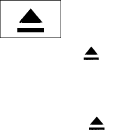
TUNE/FOLDER knob
While playing a CD with compressed audio files,
turn the TUNE/FOLDER knob right or left to play
the next or previous folder.
Text (models without Navigation System):
Select the “Text” key using the INFINITI controller
and then press the ENTER button while the CD is
being played to display the music information
below.
CD:
●Disc title
●Track title
CD with compressed audio files:
●Folder title
●File title
●Song title
●Album title
●Artist
Menu (models with Navigation System):
When the “Menu” key on the display is selected
while the CD is being played, the menu screen
will be displayed. The following menu options are
available.
●Folder List (for CD with compressed audio
files)
Displays the folder list.
●Track List
Displays the track list.
●Play Mode
Select a play mode from the following items.
– Normal
– 1 Folder Repeat (for CD with com-
pressed audio files)
– 1 Track Repeat
– 1 Disc Random
– 1 Folder Random (for CD with com-
pressed audio files)
RDM·RPT (random and repeat) button:
Press the RDM·RPT button while a compact disc
is playing to change the play pattern as follows:
CD:
Normal →1 Track Repeat →1 Disc Random →
Normal
CD with compressed audio files:
Normal →1 Folder Repeat →1 Track Repeat →
1 Disc Random →1 Folder Random →Normal
Normal: No repeat or random pattern is applied.
1 Track Repeat: the current track playing will be
repeated.
1 Disc Random: all tracks will be played ran-
domly.
1 Folder Repeat: the folder currently being ac-
cessed will be repeated.
1 Folder Random: the tracks in the current folder
being accessed will be played randomly.
CD EJECT button:
When the button is pressed with the com-
pact disc loaded, the compact disc will be
ejected.
When the button is pressed while the
compact disc is being played, the compact disc
will eject and the system will turn off.
4-76 Monitor, climate, audio, phone and voice recognition systems

Front AUX (auxiliary) input jacks (inside
center console)
The front auxiliary input jacks are located inside
the center console 䊊
1. NTSC compatible de-
vices such as video games, camcorders and
portable video players can be connected to the
auxiliary input jacks. Audio devices, such as some
MP3 players, can also be connected to the sys-
tem through the auxiliary input jacks.
The auxiliary input jacks are color coded for iden-
tification purposes:
●Red – right channel audio input
●White – left channel audio input
●Yellow – video input
Before connecting a device to the auxiliary input
jacks, turn off the power of the portable device.
With a compatible device connected to the aux-
iliary input jacks, press the DISC·AUX button
repeatedly until the AUX mode appears in the
display. The output from the device will be played
through the display (when the vehicle is in the (P)
Park position and the parking brake engaged)
and audio system. 1. Left rear passenger’s headphone jack
2. Right rear passenger’s headphone jack
3. Right rear passenger’s power on button / vol-
ume control knob
4. Rear auxiliary input jacks
5. Left rear passenger’s power on button / vol-
ume control knob
LHA2140 LHA2135
Monitor, climate, audio, phone and voice recognition systems 4-77
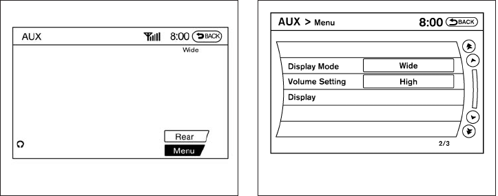
Rear AUX (auxiliary) input jacks (on back
of center console)
The rear auxiliary input jacks are located on the
back of the center console. NTSC compatible
devices such as video games, camcorders and
portable video players can be connected to the
auxiliary input jacks. Audio devices, such as some
MP3 players, can also be connected to the sys-
tem through the auxiliary input jacks.
The auxiliary input jacks are color coded for iden-
tification purposes:
●Red – right channel audio input
●White – left channel audio input
●Yellow – video input
Before connecting a device to the auxiliary input
jacks, turn off the power of the portable device.
When headphones are plugged into the rear
jacks, sound can be turned on by pressing the
volume control knob and then turning to increase
or decrease the volume.
AUX settings
Select the “Menu” key using the INFINITI control-
ler.
The display mode can be set to Normal, Wide or
Cinema. The volume setting can be set to Low,
Medium or High.
For more information about the “Rear” key, see
“Rear display settings” in this section.
LHA2150 LHA1394
4-78 Monitor, climate, audio, phone and voice recognition systems

Playing a DVD
DISC-AUX button
Park the vehicle in a safe location for the front
seat occupants to operate the DVD drive while
watching the images.
Press the DISC-AUX button until the DVD mode
is active on the display.
When a DVD is loaded, it will be replayed auto-
matically.
The operation screen will be turned on when the
DISC-AUX button is pressed while a DVD is
playing. The operation screen will turn off auto-
matically after a period of time. To turn it on again,
press the DISC-AUX button.
DVD operation keys
When the DVD is playing without the operation
screen being shown, you may use the touch-
screen to select items from the displayed video.
You may also use the INFINITI controller to select
an item from the displayed video. When the op-
eration screen is being shown, use the INFINITI
controller or the touchscreen to select an item
from the displayed menus.
PAUSE:
Select the key to pause the DVD. To re-
sume playing the DVD, use the key.
PLAY:
Select the key to start playing the DVD or
resume playing the DVD after it has been paused.
STOP:
Select the key to stop playing the DVD.
NEXT/PREVIOUS
CHAPTER:
Select the key to skip the chapter(s) of the
disc forward. Select the key to skip the
chapter(s) of the disc backward. The chapters
will advance forward or backward the number of
times the respective key is touched or selected
with the INFINITI controller.
CM SKIP:
This function is only for DVD-VIDEO and DVD-
VR. Select the or key to fast forward
or rewind a set interval of time based on the CM
settings. For more information, see “DVD set-
tings” in this section.
Top Menu:
When the “Top Menu” key is selected while the
DVD is playing, the top menu specific to each
disc will be displayed. For details, see the instruc-
tions attached to the disc.
DVD settings
Select the “Settings” key to adjust the following
settings:
●Key (DVD-VIDEO)
Displays the operation keys for the specific
DVD menu.
LHA2165
4-80 Monitor, climate, audio, phone and voice recognition systems

– Select the directional keys to move the
cursor on the DVD menu.
– Select the “Enter” key to fix the selected
menu item.
– Select the “Move” key to move the loca-
tion of the operation keys on the screen.
– Select the “Back” key to return to the
previous menu screen.
– Select the “Hide” key to hide the opera-
tion keys.
●Title Menu (DVD-VIDEO)
Some menus specific to each disc will be
shown. For details, see the instructions at-
tached to the disc.
●Title Search (DVD-VIDEO, DVD-VR)
The scene with the specified title will be
displayed the number of times the “+” or “-”
side is selected.
●Group Search (VIDEO CD)
The scene with the specified group will be
displayed the number of times the “+” or “-”
side is selected.
●10 Key Search (DVD-VIDEO, VIDEO CD,
CD-DA, DVD-VR)
Select the “10 Key Search” key to open the
number entry screen. Input the number you
want to search for and select the “OK” key.
The specified Title/Chapter or Group/Track
will be played.
●Surround Information
●Angle (DVD-VIDEO)
If the DVD contains different angles (such as
moving images), the current image angle
can be switched to another one. Select the
“Angle” key and use the “+” or “-” key to
change the angle.
●Angle Mark (DVD-VIDEO)
When this item is turned on, an angle mark
will be shown on the bottom of the screen if
the scene can be seen from a different angle.
LHA2166
Monitor, climate, audio, phone and voice recognition systems 4-81

●Menu Skip (DVD-VIDEO)
DVD menus are automatically configured
and the contents will be played directly
when the “Menu Skip” key is turned on. Note
that some discs may not be played directly
even if this item is turned on.
●CM Skip (DVD-VIDEO)
Select the “CM Skip” key to choose the
setting time for CM backward and forward
operations. Use the “+” or “-” key to choose
a setting time of 15, 30 or 60 seconds.
●DRC (DVD-VIDEO, DVD-VR)
DRC (Dynamic Range Compression) auto-
matically adjusts the soundtrack volume
level to maintain a more even sound to the
speakers.
●DOWN MIX
●DVD Language (DVD-VIDEO, VIDEO CD)
Select the “DVD Language” key to open the
number entry screen. Input the number cor-
responding to the preferred language and
select the “OK” key. The DVD top menu
language will be changed to the one speci-
fied.
●Display
Adjust the image quality of the screen by
selecting the preferred adjustment items.
●Audio
Choose the preferred language for the au-
dio.
●Subtitle (DVD-VIDEO, DVD-VR)
Choose the preferred language for the sub-
titles.
●Display Mode (DVD-VIDEO, VIDEO CD,
DVD-VR)
Choose from the “Full”, “Wide”, “Normal” or
“Cinema” mode.
●Title List (DVD-VR)
Choose the preferred title from the list.
●Play Mode
Choose the preferred play mode. The avail-
able options are “Normal” and “1 Chapter
Repeat”.
●PG/PL Mode (DVD-VR)
Choose from the “PG” or “PL” mode.
USB INTERFACE
Connecting a device to the USB input
jack
WARNING
Do not connect/disconnect or operate the
USB device while driving. Doing so can be
a distraction. If distracted you could lose
control of your vehicle and cause an acci-
dent or serious injury.
LHA2141
4-82 Monitor, climate, audio, phone and voice recognition systems

CAUTION
●Do not force the USB device into the
USB port. Inserting the USB device
tilted or up-side-down into the port may
damage the port. Make sure that the
USB device is connected correctly into
the USB port.
●Do not grab the USB port cover (if so
equipped) when pulling the USB device
out of the port. This could damage the
port and the cover.
●Do not leave the USB cable in a place
where it can be pulled unintentionally.
Pulling the cable may damage the port.
Refer to your device manufacturer’s owner infor-
mation regarding the proper use and care of the
device.
The USB input jack is located in the center con-
sole. Insert the USB device into the jack 䊊
1.
When a compatible storage device is plugged
into the jack, compatible audio files on the stor-
age device can be played through the vehicle’s
audio system.
File selection (models with Navigation
System)
When there are both audio and movie files in the
USB memory, the mode select screen is dis-
played. Use the touchscreen or the INFINITI con-
troller to select the preferred type of file. When
there is only type of file in the USB memory, that
audio or movie operation screen is displayed and
starts to play.
When you play a file with limited playing time, the
confirmation screen will be displayed before
starting to play the file. Confirm the playing time
and select “Yes” to start playing.
Audio file operation
DISC•AUX button:
Place the ignition switch in the ON or ACC
position and press the DISC•AUX button to
switch to the USB input mode. If another audio
source is playing and a USB memory device is
inserted, press the DISC•AUX button repeatedly
until the center display changes to the USB
memory mode.
If the system has been turned off while the USB
memory was playing, push the ON-OFF/VOL
control knob to restart the USB memory.
SEEK•CAT/TRACK
(Reverse or Fast Forward)
button:
Press and hold the SEEK•CAT/TRACK
button (rewind) or SEEK•CAT/TRACK
button (fast forward) for 1.5 seconds while
an audio file on the USB device is playing to
reverse or fast forward the track being played.
The track plays at an increased speed while
reversing or fast forwarding. When the button is
released, the audio file returns to normal play
speed.
LHA1378
Monitor, climate, audio, phone and voice recognition systems 4-83
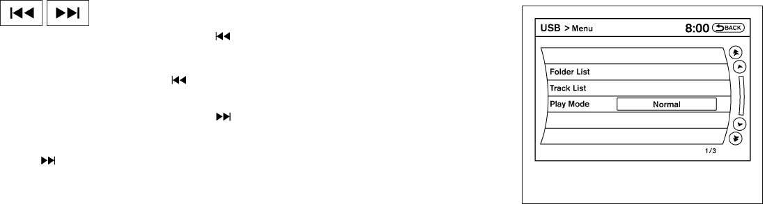
SEEK•CAT/TRACK button:
Press the SEEK•CAT/TRACK button
while an audio file on the USB device is playing to
return to the beginning of the current track. Press
the SEEK•CAT/TRACK button several
times to skip backward several tracks.
Press the SEEK•CAT/TRACK button
while an audio file on the USB device is playing to
advance one track. Press the SEEK•CAT/TRACK
button several times to skip forward sev-
eral tracks. If the last track in a folder on the USB
device is skipped, the first track of the next folder
is played.
Folder selection:
To change to another folder in the USB memory,
turn the TUNE/FOLDER knob or choose a folder
displayed on the screen.
RPT/RDM button:
When the RPT/RDM button is pressed while the
USB memory is playing, the play pattern can be
changed as follows:
Normal →1 Folder Repeat →1 Track Repeat →
All Random →1 Folder Random →Normal
Text (models without Navigation System):
Select the “Text” key using the INFINITI controller
and then press the ENTER button while a USB
memory is being played to list the music informa-
tion on the screen.
●Folder title
●File title
●Song title
●Album title
●Artist
Menu (models with Navigation System):
There are some options available during play-
back. Select one of the following that are dis-
played on the screen, if necessary. Refer to the
following information for each item.
●Movie Playback
Switch to the movie playback mode. This
item is displayed only when the USB
memory contains movie files.
The shift lever must be in Park (P) with the
parking brake engaged to watch movies
from a USB device.
LHA1294
4-84 Monitor, climate, audio, phone and voice recognition systems

●Folder List/Track List
Displays the folder or track list. The “Movie
Playback” key is also displayed in this list
screen and enables you to switch to the
movie playback mode.
●Play Mode
Choose the preferred play mode using the
INFINITI controller or the touchscreen.
Movie file operation (models with
Navigation System)
Park the vehicle in a safe location for the
front seat occupants to operate the USB
memory while watching the images.
DISC-AUX button:
When the DISC-AUX button is pushed with the
system off and the USB memory inserted, the
system will turn on. If another audio source is
playing and the USB memory is inserted, press
the DISC-AUX button repeatedly until the center
display changes to the USB memory mode.
Operation keys:
To operate the USB memory, select the desired
key displayed on the display screen.
●Pause:
Select the key to pause the movie file.
To resume playing the movie file, use
the key.
●Play:
Select the key to start playing the
movie file or resume the movie file if it has
been paused.
●Stop:
Select the key to stop playing the
movie file.
●Next Chapter/Fast Forward:
Select the key to skip the chapter(s)
of the disc forward. The chapters will ad-
vance the number of times the key is se-
lected. Press and hold the key to fast for-
ward the chapter.
LHA1379
Monitor, climate, audio, phone and voice recognition systems 4-85

●Previous Chapter/Rewind:
Select the key to skip the chapter(s)
of the disc backward. The chapters will go
back the number of times the key is selected.
Press and hold the key to rewind the chap-
ter.
List:
Select the “List” key on the movie file operation
screen to display the file list.
Settings:
Select the “Settings” key to adjust the following
settings:
●Audio File Playback
Switch to the audio playback mode. This
item is displayed only when the USB
memory contains audio files.
●Play Mode
Choose between the “Normal” or “1 Track
Repeat” play modes.
●10 Key Search
Select the “10 Key Search” key to open the
number entry screen. Input the number you
want to search for and the specified file or
folder will be played.
●Display
Adjust the image quality of the screen.
●DRC
DRC (Dynamic Range Compression) auto-
matically adjusts the soundtrack volume
level to maintain a more even sound to the
speakers.
●Audio
Choose the preferred language of the audio.
●Subtitle
Choose the preferred language of the sub-
titles.
●Display Mode
Choose between the “Normal”, “Wide”,
“Cinema” or “Full” display modes.
LHA1380
4-86 Monitor, climate, audio, phone and voice recognition systems

iPod®* PLAYER OPERATION
Connecting iPod®
WARNING
Do not connect/disconnect or operate the
USB device while driving. Doing so can be
a distraction. If distracted you could lose
control of your vehicle and cause an acci-
dent or serious injury.
CAUTION
●Do not force the USB device into the
USB port. Inserting the USB device
tilted or up-side-down into the port may
damage the port. Make sure that the
USB device is connected correctly into
the USB port.
●Do not grab the USB port cover (if so
equipped) when pulling the USB device
out of the port. This could damage the
port and the cover.
●Do not leave the USB cable in a place
where it can be pulled unintentionally.
Pulling the cable may damage the port.
Refer to your device manufacturer’s owner infor-
mation regarding the proper use and care of the
device.
To connect an iPod® to the vehicle so that the
iPod® can be controlled with the audio system
controls and display screen, use the USB jack 䊊
1
located in the center console. Connect the
iPod®-specific end of the cable to the iPod®
and the USB end of the cable to the USB jack on
the vehicle. If your iPod® supports charging via a
USB connection, its battery will be charged while
connected to the vehicle with the ignition switch
in the ACC or ON position.
While connected to the vehicle, the iPod® can
only be operated by the vehicle audio controls.
To disconnect the iPod® from the vehicle, re-
move the USB end of the cable from the USB
jack on the vehicle, then remove the cable from
the iPod®.
* iPod® is a trademark of Apple Inc., registered in
the U.S. and other countries.
Compatibility
The following models are compatible:
●iPod® 5th Generation (firmware version
1.2.3 or later)
●iPod® Classic (firmware version 1.1.1 or
later)
●iPod® Touch (firmware version 2.0.0 or
later)*
●iPod® Nano - 1st generation (firmware ver-
sion 1.3.1 or later)
●iPod® Nano - 2nd generation (firmware ver-
sion 1.1.3 or later)
●iPod® Nano - 3rd generation (firmware ver-
sion 1.1.3 or later)
●iPod® Nano - 4th generation (firmware ver-
sion 1.0.4 or later)
LHA2141
Monitor, climate, audio, phone and voice recognition systems 4-87

●iPod® Nano - 5th generation (firmware ver-
sion 1.0.1 or later)
* Some features of this iPod® may not be fully
functional.
Make sure that your iPod® firmware is updated to
the version indicated above.
Audio main operation
Place the ignition switch in the ACC or ON
position. Press the DISC·AUX button repeatedly
to switch to the iPod® mode.
If the system has been turned off while the iPod®
was playing, pressing the VOL/ON·OFF control
knob will start the iPod®.
DISC·AUX button:
When the DISC·AUX button is pressed with the
system off and the iPod® connected, the system
will turn on. If another audio source is playing and
the iPod® is connected, press the DISC·AUX
button repeatedly until the center display
changes to the iPod® mode.
LHA1397
4-88 Monitor, climate, audio, phone and voice recognition systems

Interface:
The interface for iPod® operation shown on the
vehicle center display is similar to the iPod®
interface. Use the INFINITI controller and the
BACK button to play the iPod® with your favorite
settings. The touchscreen can also be used to
control your favorite settings.
The following items can be chosen from the menu
list screen. For further information about each
item, see the iPod® Owner’s Manual.
●Now Playing
●Playlists
●Artists
●Albums
●Songs
●Podcasts
●Genres
●Composers
●Audiobooks
●Shuffle Songs
●Play Mode
The following keys shown on the screen are also
available:
●MENU: returns to the previous screen.
●: plays/pauses the music selected.
Play mode:
While the iPod® is playing, touch the “Menu” key
to display the iPod® menu. Touch the “Play
Mode” key to display the Play Mode screen and
adjust the settings for Shuffle, Repeat and Audio-
books. For further information about each item,
see the iPod® Owner’s Manual.
SEEK•CAT/TRACK buttons:
When the SEEK•CAT/TRACK button is
pressed or for less than 1.5 sec-
onds while the iPod® is playing, the next track or
the beginning of the current track on the iPod®
will be played.
LHA1398 LHA1315
Monitor, climate, audio, phone and voice recognition systems 4-89

When the SEEK•CAT/TRACK button is
pressed or for more than 1.5 sec-
onds while the iPod® is playing, the iPod® will
play while fast forwarding or rewinding. When the
button is released, the iPod® will return to the
normal play speed.
The INFINITI controller can also be used to select
tracks when the iPod® is playing.
RDM/RPT button:
When the RDM/RPT button is pressed while a
track is being played, the play pattern can be
changed as follows:
Shuffle Off/Repeat Off →Shuffle Off/Repeat 1
→Shuffle Off/Repeat All →Shuffle
Songs/Repeat Off →Shuffle Songs/Repeat All
→Shuffle Albums/Repeat Off →Shuffle Albums
Repeat All →Shuffle Off/Repeat Off
Shuffle Off/Repeat Off: the iPod® will be played
normally.
Shuffle Off/Repeat 1: the current track playing
will be repeated.
Shuffle Off/Repeat All: All tracks will be repeated.
Shuffle Songs/Repeat Off: the tracks will be
played in a mixed order.
Shuffle Songs/Repeat All: the tracks will be
played in a mixed order and will be repeated.
Shuffle Albums/Repeat Off: the albums on the
iPod® will be played in a mixed order.
Shuffle Albums Repeat All: the albums on the
iPod® will be played in a mixed order and re-
peated.
Scrolling menus:
While navigating long lists of artists, albums or
songs in the music menu, it is possible to scroll
the list by the first letter. To activate letter index-
ing, perform one of the following:
●Turn the INFINITI controller quickly.
●Press and hold the up/down directional ar-
rows on the INFINITI controller.
●Touch and hold the page up/down arrows
on the touchscreen.
LHA1399
4-90 Monitor, climate, audio, phone and voice recognition systems

To exit the scrolling by letter mode, perform one of
the following:
●Press the ENTER button on the INFINITI
controller.
●Push the ENTER switch on the steering
wheel.
●Do not touch the controls for 2 seconds.
BLUETOOTH® STREAMING AUDIO
(if so equipped)
If you have a compatible Bluetooth® audio de-
vice that is capable of playing audio files, the
device can be connected to the vehicle’s audio
system so that the audio files on the device play
through the vehicle’s speakers. Connecting Bluetooth® audio
To connect your Bluetooth® audio device to the
vehicle, follow the procedure below:
1. Press the SETTING button on the control
panel.
2. Select the “Bluetooth” key.
3. Select the “Connect Bluetooth” key.
4. A screen will appear asking if you are con-
necting the device to use with the hands-
free phone system. Select the “No” key.
LHA1316 LHA1317
Monitor, climate, audio, phone and voice recognition systems 4-91
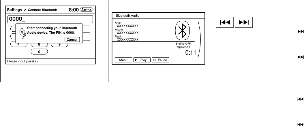
5. Enter a PIN of your choice. It will be needed
by your Bluetooth® audio device to com-
plete the connection process. See the
Bluetooth® audio device’s owner’s manual
for more information.
Audio main operation
To switch to the Bluetooth® audio mode, press
the DISC•AUX button repeatedly until the
Bluetooth® audio mode is displayed on the
screen.
The controls for the Bluetooth® audio are dis-
played on the screen.
DISC·AUX button:
Press the DISC·AUX button with the system off
and the Bluetooth® audio device connected to
turn the system on. If another audio source is
playing and the Bluetooth® audio device is con-
nected, press the DISC·AUX button repeatedly
until the display changes to the Bluetooth® audio
mode.
SEEK•CAT/TRACK button:
Press the SEEK•CAT/TRACK button for
less than 1.5 seconds while a Bluetooth® audio
file is being played to advance to the beginning of
the next track.
Press the SEEK•CAT/TRACK button for
more than 1.5 seconds while a Bluetooth® audio
file is being played to advance the track. The
Bluetooth® audio device will play while fast for-
warding. When the button is released, the
Bluetooth® audio device will return to normal
play speed.
Press the SEEK•CAT/TRACK button for
less than 1.5 seconds while a Bluetooth® audio
file is being played to return to the beginning of
the current track.
Press the SEEK•CAT/TRACK button for
more than 1.5 seconds while a Bluetooth® audio
file is being played to reverse the track. The
Bluetooth® audio device will play while revers-
ing. When the button is released, the Bluetooth®
audio device will return to normal play speed.
LHA1351 SAA2510
4-92 Monitor, climate, audio, phone and voice recognition systems

The INFINITI controller can also be used to select
tracks when the Bluetooth® audio play mode
screen is shown on the display. (“Bluetooth au-
dio” will be indicated on the header of the
screen.)
RDM/RPT button:
Press the RDM·RPT button repeatedly to change
the play mode as follows:
Normal →Shuffle All Tracks →Shuffle Group →
Repeat 1 Track →Repeat All Tracks →Repeat
Group →Normal
Operation keys:
To operate a Bluetooth® audio device, select a
key displayed on the operation screen using the
INFINITI controller.
Play
Select the “ ” key to start playing when
pausing. Select this key again to pause the audio
play.
Pause
Select the “ ” key to pause the Bluetooth ®
audio device. Select this key again to resume
playing.
Play Mode:
Select the “Menu” key to alter the play mode.
Choose the preferred play mode from the follow-
ing items:
●Shuffle
Choose from “Shuffle OFF”, “Shuffle All
Tracks” and “Shuffle Group”
●Repeat
Choose from “Repeat OFF”, “Repeat 1
Track”, “Repeat All Tracks” and “Repeat
Group”.
Bluetooth® audio settings
Press the SETTING button and select the
“Bluetooth” key to set up the Bluetooth® device
system to the preferred settings.
Bluetooth:
If this setting is turned off, the connection be-
tween the Bluetooth® devices and the in-vehicle
Bluetooth® module will be canceled.
Connect Bluetooth:
Connects to the Bluetooth® device. See “Con-
necting procedure” earlier in this section. Up to 5
devices can be registered.
LHA1316
Monitor, climate, audio, phone and voice recognition systems 4-93

Connected Devices:
Registered devices are shown on the list. Select
a Bluetooth® device from the list, the following
options will be available.
●Select
Select “Select” to connect the selected de-
vice to the vehicle. If there is a different
device currently connected, the selected
device will replace the current device.
●Edit
Rename the selected Bluetooth® device
using the keypad displayed on the screen.
●Delete
Delete the selected Bluetooth® device.
Edit Bluetooth Info:
Change the name broadcasted by this system
over Bluetooth®. Change the PIN code that is
entered when connecting a hands free device to
this system.
Replace Connected Phone:
Replace the Bluetooth® connection with a con-
nected Bluetooth® cellular phone. For details
about Hands-Free Phone System, see
“Bluetooth® Hands-Free Phone System (mod-
els with navigation system)” later in this section.
CD CARE AND CLEANING
●Handle a CD by its edges. Do not bend the
disc. Never touch the surface of the disc.
●Always place the discs in the storage case
when they are not being used.
●To clean a disc, wipe the surface from the
center to the outer edge using a clean, soft
cloth. Do not wipe the disc using a circular
motion.
●Do not use a conventional record cleaner or
alcohol intended for industrial use.
●A new disc may be rough on the inner and
outer edges. Remove the rough edges by
rubbing the inner and outer edges with the
side of a pen or pencil as illustrated.
1. Menu control switch/ENTER button
2. Back switch
3. Volume control switch
4. Power on and SOURCE select switch
STEERING WHEEL SWITCH FOR
AUDIO CONTROL
The audio system can be operated using the
controls on the steering wheel.
POWER on switch
With the ignition switch in the ACC or ON posi-
tion, push the SOURCE switch to turn the audio
system on.
LHA0049 LHA2112
4-94 Monitor, climate, audio, phone and voice recognition systems

●To avoid draining the vehicle battery, do
not operate the system for more than
15 minutes without starting the engine.
The front display is designed not to show
the images while driving, as the driver’s
attention must be given to vehicle opera-
tion for safety. Sounds are available. To
show the images in the front display, stop
the vehicle in a safe location, move the shift
lever to the P (Park) position and apply the
parking brake.
SYSTEM COMPONENTS
Rear displays
CAUTION
●The glass screen on the liquid crystal
display may break if hit with a hard or
sharp object. If the glass breaks, do not
touch the liquid crystalline material. In
case of contact with skin, wash immedi-
ately with soap and water.
●Use soft, damp cloth when cleaning the
Dual Head Restraint/Headrest DVD
System components. Do not use sol-
vents or cleaning solutions.
The rear displays are located on the back of the
front head restraints/headrests.
Use the remote controller to operate the rear
display screen.
Push the preferred side (L or R) of the power
ON/OFF button on the remote controller to acti-
vate the rear display.
The rear screens can also be activated using the
INFINITI controller. For more information, see
“Rear display settings” in this section.
Do not block the range of the wireless remote
controller receiver and wireless headphones
transmitter 䊊
1.
The angle of the rear display screen can be
adjusted for optimal viewing.
Gently apply pressure to the base of the screen
where indicated until the screen reached the
desired position. When the screen is released, it
will remain in the current position. To return to the
screen to the flat position, press the base of the
screen in all the way until it clicks and retracts.
SAA3329 LHA2210
Monitor, climate, audio, phone and voice recognition systems 4-97

Rear auxiliary input jacks
The rear auxiliary input jacks are located on the
rear of the center console. NTSC/PAL compat-
ible devices can be connected to the auxiliary
jacks. The images from the connected device can
be viewed on the rear displays.
The rear auxiliary jacks are color coded for iden-
tification purposes.
●Yellow - video input
●White - left channel audio input
●Red - right channel audio input
Before connecting a device to a jack, turn off the
power of the portable device.
To display the rear AUX screen, press the pre-
ferred side (L or R) of the AUX (L)/AUX (R)
buttons (rear input jacks) on the remote control-
ler.
The connected device from the rear auxiliary in-
put jacks cannot be displayed on the front
screen.
Headphones
The headphones for this system are a wireless
type and no cables are necessary. The head-
phones can only be used in the rear seat.
Power ON/OFF:
Press the power ON/OFF button to turn the
headphones on or off.
LHA2260 SAA3077
4-98 Monitor, climate, audio, phone and voice recognition systems
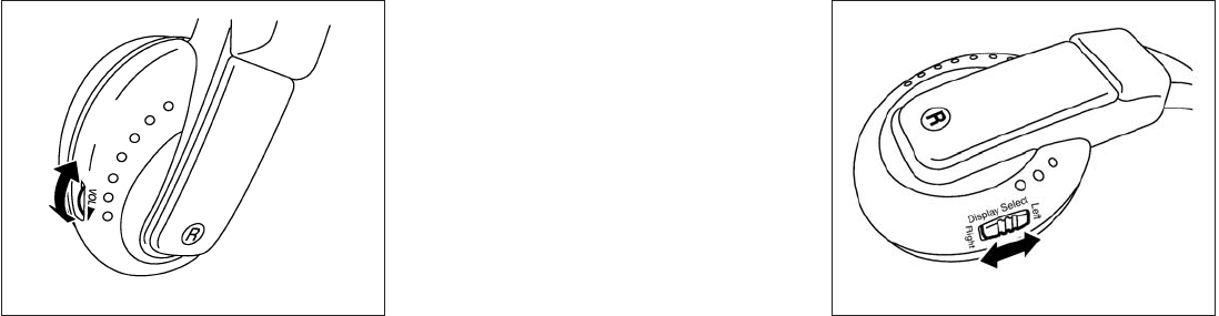
Volume control:
Turn the volume control knob to adjust the vol-
ume.
The headphones will automatically turn off after
about four minutes if there is no sound during that
period. The headphones will also turn off after
approximately four hours of continuous use. To
prevent the battery from being discharged, keep
the power turned off when not in use.
If the sound from the headphones is not clear, it
may be due to interference from an infrared com-
munication device or a cellular phone. If this
happens, turn down the headphone volume or
stop using the headphones.
It is also possible that the headphones may be
too far from the transmitter which is in the rear
display screen. This is not a malfunction.
The sound may also be interrupted temporarily
when there is an obstacle between the head-
phones and the transmitter. Remove the ob-
stacle, such as opaque materials, hands, hair,
etc.
Channel change:
When the rear displays are playing different
sources, slide the Display Select switch to select
the sound. “Left” is the sound on the left display.
“Right” is the sound on the right display.
SAA3078 LHA2672
Monitor, climate, audio, phone and voice recognition systems 4-99

The selected headphone channel (⬙Left⬙or
⬙Right⬙)䊊
1will appear on the menu screen on the
rear display.
Remote control
The remote controller has the following controls:
1. POWER button
2. Display select switch (L or R)
3. MENU button
4. Directional buttons
5. Backlight button
6. SETUP button
7. (next chapter) button
8. (fast forward) button
9. (stop) button
10. Volume control button
11. (reverse) button
12. (play and pause) button
13. (previous chapter) button
14. BACK button
15. SOURCE button
JVH0360X
LHA2673
4-100 Monitor, climate, audio, phone and voice recognition systems

Select rear displays audio source:
Slide the display select switch on the remote
control to the left (L) or right (R) to select each
screen source individually 䊊
1.
The SOURCE button on the remote control se-
lects the source for front and rear screens at
once 䊊
2.
Remote controller and headphones
battery replacement
CAUTION
●An improperly disposed battery can
harm the environment. Always confirm
local regulations for battery disposal.
●When changing batteries, do not let
dust or oil get on the components. To replace the battery:
1. Open the lid as illustrated.
●For headphones, remove the screw 䊊
1
with a flat-bladed screwdriver before re-
moving the lid.
LHA2552 SAA0978
SAA3081
Monitor, climate, audio, phone and voice recognition systems 4-101

2. Replace both batteries with new ones.
●Recommended battery:
Size AA 6 2 (DVD remote controller)
Size AAA 6 2 (headphones)
●Be careful not to touch the battery termi-
nal.
●Make sure that the (+) and (-) ends on the
batteries match the markings inside the
compartment.
3. Close the lid securely.
●If you will not be using the remote control
for long periods of time, remove the bat-
teries.
●Replacement of the batteries is needed
when the remote control only functions at
extremely close distances to the Dual
Head Restraint/Headrest DVD System or
when it does not function at all.
FCC Notice:
Changes or modifications not expressly ap-
proved by the party responsible for compli-
ance could void the user’s authority to op-
erate the equipment. This device complies
with Part 15 of the FCC Rules and RSS-210
of Industry Canada. Operation is subject to
the following two conditions: (1) This de-
vice may not cause harmful interference,
and (2) this device must accept any interfer-
ence received, including interference that
may cause undesired operation of the de-
vice.
BEFORE OPERATING DUAL HEAD
RESTRAINT/HEADREST DVD
SYSTEM
Precautions
Start the engine when using the Dual Head
Restraint/Headrest DVD System.
WARNING
The driver must not attempt to operate the
Dual Head Restraint/Headrest DVD Sys-
tem or wear the headphones while the
vehicle is in motion so that full attention
may be given to vehicle operation.
CAUTION
●Only operate the Dual Head
Restraint/Headrest DVD System while
the vehicle engine is running. Operating
the Dual Head Restraint/Headrest DVD
System for extended periods of time
with the engine OFF can discharge the
vehicle battery.
●Do not allow the system to get wet.
Excessive moisture such as spilled liq-
uids may cause the system to
malfunction.
●While playing VIDEO-CD media, this
DVD player does not guarantee com-
plete functionality of all VIDEO-CD
formats.
Parental level (parental control)
Video data with the parental control setting can
be played with this system. Please use your own
judgement to set the parental control with the
system.
Disc selection
You can play the following disc formats with the
DVD player:
●DVD-VIDEO
●VIDEO-CD
●DTS-CD
Use DVDs with the region code “ALL” or the code
applicable to your country. The region code is
displayed as a small symbol printed on the top of
the DVD. This vehicle-installed DVD player can
only play DVDs with an applicable region code.
4-102 Monitor, climate, audio, phone and voice recognition systems
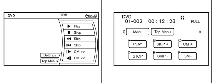
Available audio sources
The following sources are available to play on
each display:
Front display:
●Radio
●CD/DVD
●USB memory/iPod®
●Bluetooth® audio
●AUX (front)
Rear display:
●DVD
●USB memory with video files
●AUX (front/rear)
PLAYING A DIGITAL VERSATILE
DISC (DVD)
DISC·AUX button
Park the vehicle in a safe location for the
front seat occupants to operate the DVD
player while watching the images.
Insert a DVD into the CD/DVD slot with the
labeled side up. The DVD will be guided auto-
matically into the slot. When ejecting the DVD,
press the EJECT button.
Front display
SAA3069
Rear display
SAA3082
Monitor, climate, audio, phone and voice recognition systems 4-103

Press the AUX·DVD button on the control panel
and turn the display to the DVD mode, and begin
playing the DVD automatically.
When a DVD is loaded, it will begin playing
automatically.
The front screen will be turned on when the
AUX·DVD button is pressed while a DVD is being
played, and it will turn off automatically after a
period of time. To turn it on again, press the
AUX·DVD button again.
Adjust front/rear displays
Front display:
To adjust the front display mode, press the DISP
button on the center multi-function control panel.
Follow the instructions displayed on the screen.
Rear display:
To adjust the rear display mode, press the pre-
ferred side (L or R) of the DISP button on the
remote controller.
DVD operation keys
To operate the DVD player, select the preferred
key displayed on the operation screen using the
INFINITI controller.
PAUSE:
Select this key and press the ENTER button to
pause the DVD. To resume playing the DVD, use
the “PLAY” key.
To pause the DVD, it is also possible to push the
pause button on the keypad of the remote con-
troller.
PLAY:
Select this key and press the ENTER button to
start playing the DVD, for example, after pausing
the DVD.
To start playing the DVD, it is also possible to
press the play button on the keypad of the remote
controller.
STOP:
Select this key and press the ENTER button to
stop playing the DVD.
To stop playing the DVD, it is also possible to
press the stop button on the keypad of the re-
mote controller.
SKIP (FORWARD):
Select this key and press the ENTER button to
skip the chapter(s) of the disc forward. The chap-
ters will advance the number of times the ENTER
button is pressed.
To skip the chapter(s) forward, it is also possible
to press the corresponding button on the keypad
of the remote controller.
SKIP (REWIND):
Select this key and press the ENTER button to
skip the chapter(s) of the disc backward. The
chapters will go back the number of times the
ENTER button is pressed.
To skip the chapter(s) backward, it is also pos-
sible to press the corresponding button on the
keypad of the remote controller.
Commercial Skip:
This function is only for DVD-VIDEO and DVD-
VR.
Select this key to skip forward or backwards by
the set amount as defined in the DVD settings
menu.
To skip forward or backward, it is also possible to
press the corresponding button on the keypad of
the remote controller.
4-104 Monitor, climate, audio, phone and voice recognition systems
Angle (DVD-VIDEO):
If the DVD contains different angles (such as
moving images), the current image angle can be
switched to another one.
Select the “Angle” key and press the ENTER
button. When the “+”side or “⫺”side is selected,
the angle will change.
Angle Mark (DVD-VIDEO):
When this item is turned on, an angle mark will be
shown on the bottom of the screen if the scene
can be seen from a different angle.
Menu Skip (DVD-VIDEO):
DVD menus are automatically configured and the
contents will be played directly when the “Menu
Skip” key is turned on. Note that some discs may
not be played directly even if this item is turned
on.
CM Skip (DVD-VIDEO):
The amount of seconds for CM Skip can be set to
15, 30 or 60 seconds.
DRC (DVD-VIDEO):
DRC (Dynamic Range Compression) allows tun-
ing of the dynamic range of sound recorded in the
Dolby Digital format.
DVD Language (DVD-VIDEO, VIDEO-CD):
Select the “DVD Language” key and press the
ENTER button to open the number entry screen.
Input the number corresponding to the preferred
language and select the “OK” key with the
INFINITI controller. Then press the ENTER but-
ton. The DVD top menu language will be changed
to the one selected.
Display:
Adjust the image quality of the screen, select the
preferred adjustment items and press the ENTER
button.
Audio:
Choose the preferred language using the
INFINITI controller and press the ENTER button.
Subtitle (DVD-VIDEO):
Choose the preferred language using the
INFINITI controller and press the ENTER button.
To turn off the subtitles, press and hold the EN-
TER button until a beep sounds.
Display Mode (DVD-VIDEO, VIDEO-CD):
Choose from the “Full”, “Wide”, “Normal”or “Cin-
ema” mode using the INFINITI controller and
press the ENTER button.
Play Mode:
Choose the preferred play mode using the
INFINITI controller and press the ENTER button.
Remote controller operation
Use the remote controller to adjust the following
items.
Rear display ON/OFF:
The rear displays can be activated or deactivated
individually.
To activate or deactivate the rear displays, press
the preferred side (L or R) of the ON·OFF button
on the remote controller.
Joystick:
Use the joystick to select the items displayed on
the rear screen.
ENTER button:
Press the ENTER button to make the selected
item complete on the rear screen.
BACK button:
Press to go back to the previous screen or cancel
the selection.
DVD mode:
Press the DVD button to select the DVD mode.
4-106 Monitor, climate, audio, phone and voice recognition systems

AUX mode:
The AUX (auxiliary input jacks) modes can be
activated or deactivated individually. To activate
the AUX mode, press the preferred side (L or R)
of the AUX button. Press the AUX button again to
deactivate the AUX mode and display another
mode.
Volume:
To control the volume level, push the VOL
button or .
Display:
Display settings can be set individually for the
right and left screens.
Press the preferred side (L or R) of the DISP
button to adjust the rear display settings.
Sound:
To change the language, press the SOUND but-
ton. Each time the button is pressed, the lan-
guage will change to each language stored in the
DVD.
Track/Channel:
Press to skip to the previous or next DVD scene
selection.
Rear display settings
To adjust the rear display settings, select the
preferred key and press the ENTER button. The
following settings are available:
Aspect:
Select the display size from “CINEMA”, “WIDE”,
“FULL” or “NORMAL” using the joystick on the
remote controller.
Picture Mode:
To adjust the display brightness automatically,
select the “Brightness” key and then select from
“Darker”, “Normal” or “Brighter”. When adjusting
manually, select “OFF” and adjust using the joy-
stick on the remote controller and tilt the joystick
to the right or left.
To adjust tint, color, contrast or black level, select
a key using the joystick on the remote controller
and tilt the joystick to the right or left.
Press the BACK button on the remote controller
to apply the settings and return to the previous
display.
To return the adjustment levels to the default
value, select “Execute” next to “Initialization” us-
ing the joystick on the remote controller and
press the ENTER button. The “Execute” key is
deactivated when the picture mode settings are
already in the default value.
Color System:
To choose the color system, select from “NTSC”,
“PAL”, “PAL-60”, “PAL-M”, “PAL-N” or “AUTO”
using the joystick on the remote controller and tilt
the joystick to the right or left.
3D Y/C filter:
Set to ON/OFF using the joystick on the remote
controller. When turned on, small characters and
an outline of the shapes will be displayed more
clearly than when turned off.
AUX Volume Setting:
To set the AUX volume, select from “High”, “Low”
or “Middle” using the joystick on the remote con-
troller and tilt the joystick to the right or left.
OPERATING TIPS
●The images from a device that is connected
to the rear auxiliary input jacks cannot be
viewed on the front displays.
●It is not possible to switch the source to USB
(if so equipped) or DVD using the remote
controller when the rear display is in the AUX
mode. Press the AUX (L)/ (R) button in the
remote controller and turn off the AUX mode,
and then push the preferred mode switch.
Monitor, climate, audio, phone and voice recognition systems 4-107

●It is not possible to display different video
files, such as DVD or video files in the USB
memory, on the front and rear displays at the
same time.
●It is not possible to play an audio file and a
video file in the same USB memory at the
same time.
Multiple source display
It is possible to play different sources on each
display. The following example shows how to
operate multiple sources.
1. Display a video file in the front display by
selecting the DVD mode.
2. Press the L side on the power ON·OFF
button on the remote controller. The left rear
display comes on and the DVD screen will
be displayed.
3. Press the R side on the power ON·OFF
button on the remote controller. The right
rear display comes on and the DVD screen
will be displayed.
4. Switch the source on the front display to an
audio source. The sound from the speakers
switches according to the front display. The
rear display continues to display the DVD.
5. Turn on a pair of headphones and listen to
the DVD on the rear displays using the head-
phones.
6. Connect an auxiliary device into the AUX
jacks and press the AUX (L) or AUX (R)
button on the remote controller. The se-
lected side of the rear display turns to the
AUX mode. The other rear display continues
to display the DVD.
7. Turn on the other pair of headphones. If the
sound from the headphones is not from the
AUX jacks, switch the channel with the
channel select switch on the headphones.
CARE AND MAINTENANCE
Use a lightly dampened, lint free cloth to clean the
surfaces of your Dual Head Restraint/Headrest
DVD System (DVD player face, screen, remote
controller, etc.).
CAUTION
●Do not use any solvents or cleaning
solutions when cleaning the video
system.
●Do not use excessive force on the moni-
tor screen.
●Avoid touching or scratching the moni-
tor screen as it may become dirty or
damaged.
●Do not attempt to operate the system in
extreme temperature conditions [below
⫺4°F (⫺20°C) and above 158°F (70°C)]
●Do not attempt to operate the system in
extreme humidity conditions (less than
10% or more than 75%).
4-108 Monitor, climate, audio, phone and voice recognition systems

When installing a CB, ham radio or car phone in
your vehicle, be sure to observe the following
precautions; otherwise, the new equipment may
adversely affect the engine control system and
other electronic parts.
WARNING
●A cellular phone should not be used for
any purpose while driving so full atten-
tion may be given to vehicle operation.
Some jurisdictions prohibit the use of
cellular phones while driving.
●If you must make a call while your ve-
hicle is in motion, the hands free cellu-
lar phone operational mode is highly
recommended. Exercise extreme cau-
tion at all times so full attention may be
given to vehicle operation.
●If you are unable to devote full attention
to vehicle operation while talking on
the phone, pull off the road to a safe
location and stop your vehicle.
CAUTION
●Keep the antenna as far away as pos-
sible from the electronic control
modules.
●Keep the antenna wire more than 8 in
(20 cm) away from the electronic control
system harnesses. Do not route the an-
tenna wire next to any harness.
●Adjust the antenna standing-wave ratio
as recommended by the manufacturer.
●Connect the ground wire from the CB
radio chassis to the body.
●For details, consult an INFINITI retailer.
WARNING
●Use a phone after stopping your vehicle
in a safe location. If you have to use a
phone while driving, exercise extreme
caution at all times so full attention may
be given to vehicle operation.
●If you are unable to devote full attention
to vehicle operation while talking on
the phone, pull off the road to a safe
location and stop your vehicle.
CAUTION
To avoid discharging the vehicle battery,
use a phone after starting the engine.
CAR PHONE OR CB RADIO BLUETOOTH® HANDS-FREE PHONE
SYSTEM WITHOUT NAVIGATION
SYSTEM (if so equipped)
Monitor, climate, audio, phone and voice recognition systems 4-109

Your INFINITI is equipped with the Bluetooth®
Hands-Free Phone System. If you have a com-
patible Bluetooth® enabled cellular phone, you
can set up the wireless connection between your
cellular phone and the in-vehicle phone module.
With Bluetooth® wireless technology, you can
make or receive a hands-free telephone call with
your cellular phone in the vehicle.
Once your cellular phone is connected to the in-
vehicle phone module, no other phone connecting
procedure is required. Your phone is automatically
connected with the in-vehicle phone module when
the ignition switch is placed in the ON position with
the previously connected cellular phone turned on
and carried in the vehicle.
You can connect up to 5 different Bluetooth®
cellular phones to the in-vehicle phone module.
However, you can talk on only one cellular phone
at a time.
Before using the Bluetooth® Hands-Free Phone
System, refer to the following notes.
●Set up the wireless connection between a
compatible cellular phone and the in-vehicle
phone module before using the hands-free
phone system.
●
Some Bluetooth® enabled cellular phones may
not be recognized by the in-vehicle phone mod-
ule. Please visit www.InfinitiUSA.com/bluetooth
for a recommended phone list and connecting
instructions.
●You will not be able to use a hands-free
phone under the following conditions:
– Your vehicle is outside of the cellular ser-
vice area.
– Your vehicle is in an area where it is
difficult to receive a cellular signal; such
as in a tunnel, in an underground parking
garage, near a tall building or in a moun-
tainous area.
LHA2565
4-110 Monitor, climate, audio, phone and voice recognition systems

– Your cellular phone is locked to prevent it
from being dialed.
●When the radio wave condition is not ideal
or ambient sound is too loud, it may be
difficult to hear the other person’s voice dur-
ing a call.
●Do not place the cellular phone in an area
surrounded by metal or far away from the
in-vehicle phone module to prevent tone
quality degradation and wireless connection
disruption.
●While a cellular phone is connected through
the Bluetooth® wireless connection, the
battery power of the cellular phone may dis-
charge quicker than usual. The Bluetooth®
Hands-Free Phone System cannot charge
cellular phones.
●If the hands-free phone system seems to be
malfunctioning, see “Troubleshooting guide”
in this section. You can also visit
www.InfinitiUSA.com/bluetooth for trouble-
shooting help.
●Some cellular phones or other devices may
cause interference or a buzzing noise to
come from the audio system speakers. Stor-
ing the device in a different location may
reduce or eliminate the noise.
●Refer to the cellular phone Owner’s Manual
regarding the telephone charges, cellular
phone antenna and body, etc.
REGULATORY INFORMATION
FCC Regulatory information
– CAUTION: To maintain compliance with
FCC’s RF exposure guidelines, use only the
supplied antenna. Unauthorized antenna,
modification, or attachments could damage
the transmitter and may violate FCC regula-
tions.
– Operation is subject to the following two con-
ditions:
1. This device may not cause interference and
2. this device must accept any interference,
including interference that may cause unde-
sired operation of the device.
IC Regulatory information
– Operation is subject to the following two con-
ditions: (1) this device may not cause interfer-
ence, and (2) this device must accept any
interference, including interference that may
cause undesired operation of the device.
– This Class B digital apparatus meets all re-
quirements of the Canadian Interference-
Causing Equipment Regulations.
BLUETOOTH® is a
trademark owned by
Bluetooth SIG, Inc.
and licensed to
Visteon.
USING THE SYSTEM
The INFINITI Voice Recognition system allows
hands-free operation of the Bluetooth® Phone
System.
If the vehicle is in motion, some commands may
not be available so full attention may be given to
vehicle operation.
Initialization
When the ignition switch is placed in the ON
position, INFINITI Voice Recognition is initialized,
which takes a few seconds. If the button is
pressed before the initialization completes, the
system will announce “Hands-free phone system
not ready” and will not react to voice commands.
Monitor, climate, audio, phone and voice recognition systems 4-111

Operating tips
To get the best performance out of the INFINITI
Voice Recognition system, observe the following:
●Keep the interior of the vehicle as quiet as
possible. Close the windows to eliminate
surrounding noises (traffic noises, vibration
sounds, etc.), which may prevent the system
from recognizing voice commands correctly.
●Wait until the tone sounds before speaking a
command. Otherwise, the command will not
be received properly.
●Start speaking a command within 5 seconds
after the tone sounds.
●Speak in a natural voice without pausing
between words.
Giving voice commands
To operate INFINITI Voice Recognition, press and
release the button located on the steering
wheel. After the tone sounds, speak a command.
The command given is picked up by the micro-
phone, and voice feedback is given when the
command is accepted.
●If you need to hear the available commands
for the current menu again, say “Help” and
the system will repeat them.
●If a command is not recognized, the system
announces, “Command not recognized.
Please try again.” Make sure the command is
said exactly as prompted by the system and
repeat the command in a clear voice.
●If you want to go back to the previous com-
mand, you can say “Go back” or “Correc-
tion” any time the system is waiting for a
response.
●You can cancel a command when the sys-
tem is waiting for a response by saying,
“Cancel” or “Quit.” The system announces
“Cancel” and ends the VR session. You can
also press and hold the button on the
steering wheel for 5 seconds at any time to
end the VR session. Whenever the VR ses-
sion is cancelled, a double beep is played to
indicate you have exited the system.
●If you want to adjust the volume of the voice
feedback, press the volume control switches
(+ or -) on the steering wheel while being
provided with feedback. You can also use
the radio volume control knob.
●In most cases you can interrupt the voice
feedback to speak the next command by
pressing the button on the steering
wheel.
●To use the system faster, you may speak the
second level commands with the main menu
command on the main menu. For example,
press the button and after the tone
say, “Call Redial.”
How to say numbers
INFINITI Voice Recognition requires a certain
way to speak numbers in voice commands. Refer
to the following rules and examples.
●Either “zero” or “oh” can be used for “0”.
Example: 1-800-662-6200
– “One eight oh oh six six two six two oh
oh”, or
– “One eight zero zero six six two six two oh
oh”
●Words can be used for the first 4 digits
places only.
Example: 1-800-662-6200
– “One eight hundred six six two six two oh
oh”,
– NOT “One eight hundred six six two sixty
two hundred,” and
– NOT “One eight oh oh six six two sixty two
hundred”
4-112 Monitor, climate, audio, phone and voice recognition systems

●Numbers can be spoken in small groups.
The system will prompt you to continue en-
tering digits, if desired.
Example: 1-800-662-6200
– “One eight zero zero”
The system repeats the numbers and
prompts you to enter more.
– “six six two”
The system repeats the numbers and
prompts you to enter more.
– “six two zero zero”
●Say “pound” for “#”. Say “star” for “*” (avail-
able when using the “Special Number” com-
mand and the “Send” command during a
call).
See “List of voice commands” and “Special
number” in this section for more information.
Example: 1-555-1212 *123
– “One five five five one two one two star
one two three”
●Say “plus” for “+” (available only when using
the “Special Number” command).
●Say “pause” for a 2-second pause (available
only when storing a phone book number).
NOTE:
For best results, say phone numbers as
single digits.
The voice command “Help” is available at any
time. Please use the “Help” command to get
information on how to use the system.
CONTROL BUTTONS
The control buttons for the Bluetooth® Hands-
Free Phone System are located on the steering
wheel.
PHONE/SEND
Press the button to initiate a
VR session or answer an incoming
call.
LHA2566
Monitor, climate, audio, phone and voice recognition systems 4-113

You can also use the button
to interrupt the system feedback
and give a command at once. See
“List of voice commands” and
“During a call” in this section for
more information.
PHONE/END
While the voice recognition system
is active, press and hold the
button for 5 seconds to quit the
voice recognition system at any
time.
TUNING SWITCH
While using the voice recognition
system, tilt the tuning switch up or
down to manually control the
phone system.
GETTING STARTED
The following procedures will help you get
started using the Bluetooth® Hands-Free Phone
System with INFINITI Voice Recognition. For ad-
ditional command options, refer to “List of voice
commands” in this section.
Choosing a language
You can interact with the Bluetooth® Hands-
Free Phone System using English, Spanish or
French.
To change the language, perform the following.
1. Press the SETTING button on the control
panel
2. Select the “Language & Units” key
3. Select desired language and press enter on
the control panel
Connecting procedure
NOTE:
The connecting procedure must be per-
formed when the vehicle is stationary. If the
vehicle starts moving during the procedure,
the procedure will be cancelled.
Main Menu
“Connect phone” 䊊
A
“Add phone” 䊊
B
Initiate from handset 䊊
C
Name phone 䊊
D
1. Press the button on the steering
wheel. The system announces the available
commands.
2. Say: “Connect phone” 䊊
A. The system ac-
knowledges the command and announces
the next set of available commands.
3. Say: “Add phone” 䊊
B. The system acknowl-
edges the command and asks you to initiate
connecting from the phone handset 䊊
C.
The connecting procedure of the cellular
phone varies according to each cellular
phone model. See the cellular phone Own-
er’s Manual for details. You can also visit
www.InfinitiUSA.com/bluetooth for instruc-
tions on connecting INFINITI recommended
cellular phones.
When prompted for a Passkey code, enter
“1234” from the handset. The Passkey code
“1234” has been assigned by INFINITI and
cannot be changed.
4. The system asks you to say a name for the
phone 䊊
D.
If the name is too long or too short, the
system tells you, then prompts you for a
name again.
Also, if more than one phone is connected
and the name sounds too much like a name
already used, the system tells you, then
prompts you for a name again.
4-114 Monitor, climate, audio, phone and voice recognition systems

Making a call by entering a phone
number
Main Menu
“Call” 䊊
A
“Phone Number” 䊊
B
Speak the digits 䊊
C
“Dial” 䊊
D
1. Press the button on the steering
wheel. A tone will sound.
2. Say: “Call” 䊊
A. The system acknowledges
the command and announces the next set of
available commands.
3. Say “Phone Number” 䊊
B. The system ac-
knowledges the command and announces
the next set of available commands.
4. Say the number you wish to call starting with
the area code in single digit format 䊊
C.Ifthe
system has trouble recognizing the correct
phone number, try entering the number in
the following groups: 3-digit area code,
3-digit prefix and the last 4-digits. For ex-
ample, 555-121-3354 can be said as “five
five five” as the 1st group, then “one two
one” as the 2nd group, and “three three five
four” as the 3rd group. For dialing more than
10 digits or any special characters, say
“Special Number”. See “How to say num-
bers” in this section for more information.
5. When you have finished speaking the phone
number, the system repeats it back and an-
nounces the available commands.
6. Say: “Dial” 䊊
D. The system acknowledges
the command and makes the call.
For additional command options, see “List of
voice commands” in this section.
Receiving a call
When you hear the ring tone, press the
button on the steering wheel.
Once the call has ended, press the button
on the steering wheel.
NOTE:
If you do not wish to take the call when you
hear the ring tone, press the button
on the steering wheel.
For additional command options, see “List of
voice commands” in this section.
LIST OF VOICE COMMANDS
Main Menu
“Call”
“Phonebook”
“Recent Calls”
“Connect Phone”
When you press and release the button on
the steering wheel, you can choose from the
commands on the Main Menu. The following
pages describe these commands and the com-
mands in each sub-menu.
Remember to wait for the tone before
speaking.
After the main menu, you can say “Help” to hear
the list of commands currently available any time
the system is waiting for a response.
If you want to end an action without completing it,
you can say “Cancel” or “Quit” at any time the
system is waiting for a response. The system will
end the VR session. Whenever the VR session is
cancelled, a double beep is played to indicate
you have exited the system.
If you want to go back to the previous command,
you can say “Go back” or “Correction” any time
the system is waiting for a response.
Monitor, climate, audio, phone and voice recognition systems 4-115

The system announces, “Transfer call. Call
transferred to privacy mode.” The system
then ends the VR session.
To reconnect the call from the cellular phone
to the Bluetooth® Hands-Free System,
press the button.
●“Mute” — Use the Mute command to mute
your voice so the other party cannot hear it.
Use the mute command again to unmute
your voice.
NOTE:
If a call is ended or the cellular phone
network connection is lost while the Mute
feature is on, the Mute feature will be reset
to “off” for the next call so the other party
can hear your voice.
“Phonebook” (phones without
automatic phonebook download
function)
NOTE:
The “Transfer Entry” command is not avail-
able when the vehicle is moving.
Main Menu
“Phonebook”
“Transfer Entry” 䊊
A
“Delete Entry” 䊊
B
“List Names” 䊊
C
For phones that do not support automatic down-
load of the phonebook (PBAP Bluetooth® pro-
file), the “Phonebook” command is used to manu-
ally add entries to the vehicle phonebook.
The phonebook stores up to 40 names for each
phone connected to the system.
NOTE:
Each phone has its own separate phone-
book. You cannot access Phone A’s phone-
book if you are currently connected with
Phone B.
“Transfer Entry” 䊊
A
Use the Transfer Entry command to store a new
name in the system.
When prompted by the system, say the name you
would like to give the new entry.
For example, say: “Mary.”
If the name is too long or too short, the system
tells you, then prompts you for a name again.
Also, if the name sounds too much like a name
already stored, the system tells you, then prompts
you for a name again.
The system will ask you to transfer a phone
number stored in the cellular phone’s memory.
Enter a phone number by voice command:
For example, say: “five five five one two one two.”
See “How to say numbers” in this section for
more information.
To transfer a phone number stored in the cellular
phone’s memory:
Say “Transfer entry.” The system acknowledges
the command and asks you to initiate the transfer
from the phone handset. The new contact phone
number will be transferred from the cellular
phone via the Bluetooth® communication link.
The transfer procedure varies according to each
cellular phone. See the cellular phone Owner’s
Manual for details. You can also visit
www.InfinitiUSA.com/bluetooth for instructions
on transferring phone numbers from INFINITI rec-
ommended cellular phones.
The system repeats the number and prompts you
for the next command. When you have finished
entering numbers or transferring an entry, choose
“Store.”
Monitor, climate, audio, phone and voice recognition systems 4-117

The system confirms the name, location and
number.
“Delete Entry” 䊊
B
Use the Delete Entry command to erase one
entry from the phonebook. After the system rec-
ognizes the command, speak the name to delete
or say “List Names” to choose an entry.
“List Names” 䊊
C
Use the List Names command to hear all the
names in the phonebook.
The system recites the phonebook entries but
does not include the actual phone numbers.
When the playback of the list is complete, the
system goes back to the main menu.
You can stop the playback of the list at any time
by pressing the button on the steering
wheel. The system ends the VR session.
“Phonebook” (phones with automatic
phonebook download function)
NOTE:
The “Transfer Entry” command is not avail-
able when the vehicle is moving.
Main Menu
“Phonebook”
SayaName
“List Names” 䊊
A
“Record Name” 䊊
B
For phones that support automatic download of
the phonebook (PBAP Bluetooth® profile), the
“Phonebook” command is used to manage en-
tries in the vehicle phonebook. You can say the
name of an entry at this menu to initiate dialing of
that entry.
The phonebook stores up to 1000 names for
each phone connected to the system.
When a phone is connected to the system, the
phonebook is automatically downloaded to the
vehicle. This feature allows you to access your
phonebook from the Bluetooth® system and call
contacts by name. You can record a custom
voice tag for contact names that the system has
difficulty recognizing. For more information see
“Record name” in this section.
NOTE:
Each phone has its own separate phone-
book. You cannot access Phone A’s phone-
book if you are currently connected with
Phone B.
“List Names” 䊊
A
Use the List Names command to hear all the
names and locations in the phone book.
The system recites the phone book entries but
does not include the actual phone numbers.
When the playback of the list is complete, the
system goes back to the main menu.
You can stop the playback of the list at any time
by pressing the button on the steering
wheel. The system ends the VR session. See the
“Record name” command in this section for infor-
mation about recording custom voice tags for list
entries that the system has difficulty pronounc-
ing.
“Record Name” 䊊
B
The system allows you to record custom voice
tags for contact names in the phonebook that the
vehicle has difficulty recognizing. This feature can
also be used to record voice tags to directly dial
an entry with multiple numbers. Up to 40 voice
tags can be recorded to the system.
4-118 Monitor, climate, audio, phone and voice recognition systems

“Recent Calls”
Main Menu
“Recent Calls”
“Outgoing” 䊊
A
“Incoming” 䊊
B
“Missed” 䊊
C
“Call Back” 䊊
D
“Redial” 䊊
E
Use the Recent Calls command to access out-
going, incoming, missed calls and to call back the
last incoming call or to redial the last outgoing
call.
“Outgoing” 䊊
A
Use the Outgoing command to list the outgoing
calls made from the vehicle.
“Incoming” 䊊
B
Use the Incoming command to list the incoming
calls made to the vehicle.
“Missed” 䊊
C
Use the Missed command to list the calls made to
the vehicle that were not answered.
“Call Back” 䊊
D
Use the Call Back command to dial the number of
the last incoming call to the vehicle.
“Redial” 䊊
E
Use the Redial command to dial the number of
the last outgoing call from the vehicle.
“Connect Phone”
NOTE:
The Add Phone command is not available
when the vehicle is moving.
Main Menu
“Connect Phone”
“Add Phone” 䊊
A
“Select Phone” 䊊
B
“Replace Phone” 䊊
C
“Delete Phone” 䊊
D
“Turn Bluetooth OFF” 䊊
E
Use the Connect Phone commands to manage
the phones connecting to the vehicle or to enable
the Bluetooth® function on the vehicle.
“Add Phone” 䊊
A
Use the Add Phone command to add a phone to
the vehicle. See “Connecting procedure” in this
section for more information.
“Select Phone” 䊊
B
Use the Select Phone command to select from a
list of phones connected to the vehicle. The sys-
tem will list the names assigned to each phone
and then prompt you for the phone you wish to
select. Only one phone can be active at a time.
“Replace Phone” 䊊
C
Use the Replace Phone command to replace an
existing phone pairing with a new phone. The
system will keep all voice tags assigned to your
phonebook.
“Delete Phone” 䊊
D
Use the Delete Phone command to delete a
phone that is connected to the vehicle. The sys-
tem will list the names assigned to each phone
and then prompt you for the phone you wish to
delete. Deleting a phone from the vehicle will also
delete that phonebook for that phone.
“Turn Bluetooth OFF” 䊊
E
Use the Turn Bluetooth OFF command to prevent
a wireless connection to your phone.
Monitor, climate, audio, phone and voice recognition systems 4-119

VOICE ADAPTATION (VA) MODE
Voice Adaptation allows up to two out-of-dialect
users to train the system to improve recognition
accuracy. By repeating a number of commands,
the users can create a voice model of their own
voice that is stored in the system. The system is
capable of storing a different voice adaptation
model for each connected phone.
Training procedure
The procedure for training a voice is as follows.
1. Position the vehicle in a reasonably quiet
outdoor location.
2. Sit in the driver’s seat with the engine run-
ning, the parking brake on, and the transmis-
sion in P (Park).
3. Press and hold the button for approxi-
mately 5 seconds.
4. The system announces: “Press the
PHONE/SEND ( ) button for the
hands-free phone system to enter the voice
adaptation mode or press the PHONE/END
() button to select a different lan-
guage.”
5. Press the button.
For information on selecting a different lan-
guage, see “Choosing a language” in this
section.
6. Voice memory A or memory B is selected
automatically. If both memory locations are
already in use, the system will prompt you to
overwrite one. Follow the instructions pro-
vided by the system.
7. When preparation is complete and you are
ready to begin, press the button.
8. The VA mode will be explained. Follow the
instructions provided by the system.
9. When training is finished, the system will tell
you an adequate number of phrases have
been recorded.
10. The system will announce that voice adap-
tation has been completed and the system is
ready.
The VA mode will stop if:
●The button is pressed for approxi-
mately 5 seconds in VA mode.
●The vehicle begins moving during VA mode.
●The ignition switch is placed in the OFF or
LOCK position.
Training phrases
During the VA mode, the system instructs the
trainer to say the following phrases. (The system
will prompt you for each phrase.)
●phonebook transfer entry
●dial three oh four two nine
●delete call back number
●incoming
●transfer entry
●eight pause nine three two pause seven
●delete all entries
●call seven two four zero nine
●phonebook delete entry
●next entry
●dial star two one seven oh
●yes
●no
●select
●missed
●dial eight five six nine two
●Bluetooth on
4-120 Monitor, climate, audio, phone and voice recognition systems

●outgoing
●call three one nine oh two
●nine seven pause pause three oh eight
●cancel
●call back number
●call star two zero nine five
●delete phone
●dial eight three zero five one
●record name
●four three pause two nine pause zero
●delete redial number
●phonebook list names
●call eight oh five four one
●correction
●connect phone
●dial seven four oh one eight
●previous entry
●delete
●dial nine seven two six six
●call seven six three oh one
●go back
●call five six two eight zero
●dial six six four three seven
MANUAL CONTROL
While using the voice recognition system, it is
possible to select menu options by using the
steering wheel controls instead of speaking voice
commands. This can be especially helpful if the
noise of driving makes it difficult for the voice
recognition system to accurately interpret com-
mands. The manual control mode does not allow
dialing a phone number by digits. The user may
select an entry from the Phonebook or Recent
Calls lists. To re-activate voice recognition, exit
the manual control mode by pressing and holding
the PHONE/END ( ) button. At that time,
pressing the PHONE/SEND ( ) button will
start the Hands Free Phone System.
Operating tips
●To enter manual control mode, start the
voice recognition system and tilt the tuning
() switch up or down. The system will
speak ⬙Showing Manual Options⬙when
manual controls are initially activated.
●To browse the menu options, tilt the tuning
() switch up or down. The system will
always speak the current menu option. De-
pending on the audio display, it will also
show the current menu option.
●To select the current menu option, press the
PHONE/SEND ( ) button.
●To go back to the previous menu, press the
PHONE/END ( ) button. If the current
menu is the Main Menu, pressing the
PHONE/END ( ) button will exit the
Phone system.
●To exit the manual control mode, press and
hold the PHONE/END ( ) button for
5 seconds.
Monitor, climate, audio, phone and voice recognition systems 4-121

TROUBLESHOOTING GUIDE
The system should respond correctly to all voice
commands without difficulty. If problems are en-
countered, try the following solutions.
Where the solutions are listed by number, try
each solution in turn, starting with number 1, until
the problem is resolved.
Symptom Solution
System fails to interpret the command correctly.
1. Ensure that the command is valid. See “List of voice commands” in this section.
2. Ensure that the command is spoken after the tone.
3. Speak clearly without pausing between words and at a level appropriate to the ambient noise level in the vehicle.
4. Ensure that the ambient noise level is not excessive (for example, windows open or defroster on). NOTE: If it is too
noisy to use the phone, it is likely that the voice commands will not be recognized.
5. If more than one command was said at a time, try saying the commands separately.
6. If the system consistently fails to recognize commands, the voice training procedure should be carried out to im-
prove the recognition response for the speaker. See “Voice Adaptation (VA) mode” in this section.
The system consistently selects the wrong entry from the
phone book.
1. Ensure that the phone book entry name requested matches what was originally stored. This can be confirmed by
using the “List Names” command. See “Phonebook” in this section.
2. Replace one of the names being confused with a new name.
4-122 Monitor, climate, audio, phone and voice recognition systems

WARNING
●Use a phone after stopping your vehicle
in a safe location. If you have to use a
phone while driving, exercise extreme
caution at all times so full attention may
be given to vehicle operation.
●If you are unable to devote full attention
to vehicle operation while talking on
the phone, pull off the road to a safe
location and stop your vehicle.
CAUTION
To avoid discharging the vehicle battery,
use a phone after starting the engine.
Your INFINITI is equipped with the Bluetooth®
Hands-Free Phone System. If you have a com-
patible Bluetooth® enabled cellular phone, you
can set up the wireless connection between your
cellular phone and the in-vehicle phone module.
With Bluetooth® wireless technology, you can
make or receive a hands-free telephone call with
your cellular phone in the vehicle.
Once your cellular phone is connected to the
in-vehicle phone module, no other phone con-
necting procedure is required. Your phone is
automatically connected with the in-vehicle
LHA2477
BLUETOOTH® HANDS-FREE PHONE
SYSTEM WITH NAVIGATION SYSTEM
(if so equipped)
Monitor, climate, audio, phone and voice recognition systems 4-123
phone module when the ignition switch is placed
in the ON position with the connected cellular
phone turned on and carried in the vehicle.
You can register up to 5 different Bluetooth®
cellular phones to the in-vehicle phone module.
However, you can talk on only one cellular phone
at a time.
INFINITI Voice Recognition system supports the
phone commands, so dialing a phone number
using your voice is possible. For more details, see
“INFINITI Voice Recognition System” in this sec-
tion.
Before using the Bluetooth® Hands-Free Phone
System, refer to the following notes.
●Set up the wireless connection between a
cellular phone and the in-vehicle phone
module before using the hands-free phone
system.
●Some Bluetooth® enabled cellular phones
may not be recognized by the in-vehicle
phone module. Please visit
www.InfinitiUSA.com/bluetooth for a rec-
ommended phone list and connecting.
●You will not be able to use a hands-free
phone under the following conditions:
– Your vehicle is outside of the cellular ser-
vice area.
– Your vehicle is in an area where it is
difficult to receive cellular signal; such as
in a tunnel, in an underground parking
garage, near a tall building or in a moun-
tainous area.
– Your cellular phone is locked to prevent it
from being dialed.
●When the radio wave condition is not ideal
or ambient sound is too loud, it may be
difficult to hear the other person’s voice dur-
ing a call.
●Immediately after the ignition switch is
placed in the ON position, it may be impos-
sible to receive a call for a short period of
time.
●Do not place the cellular phone in an area
surrounded by metal or far away from the
in-vehicle phone module to prevent tone
quality degradation and wireless connection
disruption.
●While a cellular phone is connected through
the Bluetooth® wireless connection, the
battery power of the cellular phone may dis-
charge quicker than usual. The Bluetooth®
Hands-Free Phone System cannot charge
cellular phones.
●If the hands-free phone system seems to be
malfunctioning, see “Troubleshooting guide”
in this section. You can also visit
www.InfinitiUSA.com/bluetooth for trouble-
shooting help.
●Some cellular phones or other devices may
cause interference or a buzzing noise to
come from the audio system speakers. Stor-
ing the device in a different location may
reduce or eliminate the noise.
●Refer to the cellular phone owner’s manual
regarding the telephone charges, cellular
phone antenna and body, etc.
●The signal strength display on the monitor
will not coincide with the signal strength
display of some cellular phones.
●If reception between callers is unclear, ad-
justing the incoming or outgoing call volume
may improve the clarity. See “Call volume” in
this section.
4-124 Monitor, climate, audio, phone and voice recognition systems

REGULATORY INFORMATION
FCC Regulatory information
– CAUTION: To maintain compliance with
FCC’s RF exposure guidelines, use only the
supplied antenna. Unauthorized antenna,
modification, or attachments could damage
the transmitter and may violate FCC regula-
tions.
– Operation is subject to the following two con-
ditions:
1. This device may not cause interference and
2. this device must accept any interference,
including interference that may cause unde-
sired operation of the device.
IC Regulatory information
– Operation is subject to the following two con-
ditions: (1) this device may not cause interfer-
ence, and (2) this device must accept any
interference, including interference that may
cause undesired operation of the device.
– This Class B digital apparatus meets all re-
quirements of the Canadian Interference-
Causing Equipment Regulations.
BLUETOOTH® is a
trademark owned by
Bluetooth SIG, Inc.
and licensed to
Clarion.
VOICE COMMANDS
You can use voice commands to operate various
Bluetooth® Hands-Free Phone System features
using the INFINITI Voice Recognition system. For
more details, see “INFINITI Voice Recognition
System” in this section.
Monitor, climate, audio, phone and voice recognition systems 4-125

CONNECTING PROCEDURE
Press the SETTING button on the control panel,
then select the “Bluetooth” key on the display.
Menu Item Result
Bluetooth ON/OFF Allows user to switch Bluetooth on and off. Bluetooth must be on in order to connect device
On Turns Bluetooth on
Off Turns Bluetooth off
Connect Bluetooth Upon pressing this button, a popup box will appear on the screen, prompting you to confirm that the connection is for the phone system. Select the
⬙Yes⬙key.
Yes Confirms that you are connecting a Bluetooth device. Upon pressing this button, the following message will appear on screen. ⬙The system is
searching for your phone. Using your handset, look for a Bluetooth device called MY-CAR. When requested by the handset, enter the PIN 1234. Ex-
iting screen cancels search.⬙The connecting procedure phone varies by phone. See phone Owner’s Manual for details. When the connecting is
complete, the screen will return to the Bluetooth settings screen.
Cancel Cancels operation
No Indicates to the system that you are connecting a Bluetooth enabled audio device
Cancel Cancels operation
LHA2152
4-126 Monitor, climate, audio, phone and voice recognition systems

HANDSET PHONEBOOK
Many phones will support an automatic down-
load of the cellular phone’s phonebook. Since
this method allows for up to 1000 numbers to be
stored and entries are automatically assigned
voice tags by the system, this is a useful function
for easy dialing supported by the Voice Recogni-
tion system.
Transferring the handset phonebook
If your cellular phone supports automatic down-
loading, the system transfers the handset phone-
book automatically by default. To ensure that this
feature is activated, press the SETTING button
on the instrument panel and select the “Phone”
key. The “Auto Downloaded” selection should
have the amber indicator next to the word ON
activated. Select the “Auto Downloaded” key to
toggle this feature on or off.
To transfer the handset phonebook to the vehicle
manually, follow these steps:
1. Press the SETTING button on the control
panel.
2. Select the “Phone” key.
3. Select the “Download Handset Phonebook”
key.
Once the handset phonebook is transferred to
the vehicle, it can be accessed by pressing the
PHONE key on the instrument panel or the
button on the steering wheel, then selecting the
“Handset Phonebook” key.
Whether the handset phonebook is transferred
manually or automatically, the process can take
up to five minutes to complete, depending on the
size of the handset phonebook. See the cellular
phone’s owner’s manual for more details.
LHA1319
4-128 Monitor, climate, audio, phone and voice recognition systems

RECEIVING A CALL
When you hear a phone ring, the display will
change to phone mode. To receive a call, follow
one of the procedures listed below:
Menu Item Result
Press the
button on the steering wheel
Accept an incoming call to talk
⬙Answer⬙key on the display Accept an incoming call to talk
⬙Hold Call⬙key on the display Put an incoming call on hold
⬙Reject Call⬙key on the display Reject an incoming call
DURING A CALL
There are some options available during a call. Select one of the following displayed on the screen, if necessary:
Menu Item Result
Hang Up Finish the call. If pressed while another caller is on hold, current call will be ended and user will be able to speak to the caller that was previously on hold.
Use Handset Transfer the call to the cellular phone.
Mute Mute your voice to the person.
Cancel
Mute
This will appear after the ⬙Mute⬙key is selected. Mute will be cancelled.
Keypad Brings up a keypad. Enter digits when needed. For example, entering your PIN number for voicemail.
Note Press the
button during a call to send numbers and digits using Voice Recognition.
Switch Call Select this option to answer another incoming call (function may not be available depending on the model of the phone).
4-130 Monitor, climate, audio, phone and voice recognition systems

ENDING A CALL
To finish the call, perform one of the following
procedures:
Menu Item Result
⬙Hang up⬙key on the ⬙Call in Prog-
ress⬙Display
Finish the call.
button on the steering wheel Finish the call.
PHONE SETTINGS
To set up the Bluetooth Hands-Free Phone System to your perferred settings, press the SETTING button on the control panel and select the ⬙Phone⬙key
on the display.
Menu Item Result
Edit Vehicle Phonebook See ⬙Vehicle Phonebook⬙in this section for adding, editing, and deleting contacts in the vehicle phonebook.
Delete Phonebook Delete a phonebook stored on the system.
Download Handset Phonebook See ⬙Handset Phonebook⬙in this section for adding, editing, and deleting contacts in the handset phonebook.
Volume and Ringtone Adjust the volume level of the ringtone, incoming call sound and outgoing call sound.
Automatic Hold When this option is turned on, an incoming call will be placed on hold automatically after several rings.
Vehicle Ringtone When this option is turned on, a specific ringtone that is different than the cellular phone’s will sound when receiving a call.
Auto Downloaded See “Handset Phonebook” in this section for information about automatically downloading the handset phonebook.
Monitor, climate, audio, phone and voice recognition systems 4-131

BLUETOOTH SETTINGS
To set up the Bluetooth Hands-Free Phone Sys-
tem to your preferred settings, press the SET-
TING button on the control panel and select the
⬙Bluetooth⬙key on the display.
Menu Item Result
Bluetooth Turn the Bluetooth system on or off.
Connect Bluetooth See ⬙Connecting Procedure⬙in this section for more information about connecting a
phone.
Connected Devices Display a list of the Bluetooth devices connected to the system.
Edit Bluetooth Info Check information about the device name, device address, and device PIN.
Replaced Connected
Phone
Replace the phone currently connected to the system. This option allows you to keep an
voicetags that were recorded using the previous phone.
4-132 Monitor, climate, audio, phone and voice recognition systems

CALL VOLUME
Adjusting the incoming or outgoing call volume
may improve clarity if reception between callers is
unclear. To access the volume settings, press the
SETTING button, then select ”Volume and
Beeps”. You can also adjust the volume of an
incoming voice during a call by pushing the vol-
ume control switch on the steering wheel or by
turning the volume control knob on the control
panel:
Menu Item Result
Ringtone Adjusting this setting allows ringer volume to be set at a desired level.
Incoming Call Adjusting this setting allows you to hear a difference in volume (You can also adjust the volume of an incoming voice during a call by
pushing the volume control switch on the steering wheel or by turning the volume control knob.
Outgoing Call Adjusting this setting allows the person you are talking with to hear a difference in volume.
Monitor, climate, audio, phone and voice recognition systems 4-133

INFINITI Voice Recognition allows hands-free
operation of the systems equipped on this ve-
hicle, such as phone and vehicle information.
There are two voice recognition modes of opera-
tion available. They are:
●Standard Mode
●Alternate Command Mode
In Standard Mode (the factory default setting),
commands that are available are always shown
on the display and announced by the system. You
can complete your desired operation by simply
following the prompts given by the system. Not all
INFINITI Voice Recognition options are available
while in Standard Mode.
For advanced operation, you can change to an
Alternate Command Mode that enables the op-
eration of the display and audio system through
INFINITI Voice Recognition. When this mode is
active, an expanded list of commands can be
spoken after pushing the TALK switch on
the steering wheel, and the voice command
menu prompts are turned off.
In Alternate Command Mode the recognition
success rate may be affected because the num-
ber of available commands and the ways of
speaking each command are increased. See
“INFINITI Voice Recognition Alternate Command
Mode” in this section.
To improve the recognition success rate when
Alternate Command Mode is active, try using the
Speaker Adaptation Function available in that
mode. See “Speaker Adaptation Function” in this
section. Otherwise, it is recommended that Alter-
nate Command Mode be turned off and Standard
Mode be used for the best recognition perfor-
mance.
While using the INFINITI Voice Recognition sys-
tem for certain Phone and Navigation features,
you can switch to using manual controls (touch-
screen, INFINITI controller, steering wheel con-
trols) and the information you have already en-
tered by voice control will be retained. To switch
to manual controls, select the “Manual Controls”
key on the display when it appears. The system
will respond by speaking “Changing to manual
operation. Please use manual controls to con-
tinue.”
For the voice commands for the navigation sys-
tem, refer to the Navigation System Owner’s
Manual of your vehicle.
For vehicles in the U.S., the factory default setting
is the Standard Mode. See “Standard Mode” in
this section. For vehicles in Canada, the factory
default setting is the Alternate Command Mode.
See “Alternate Command Mode” in this section.
INFINITI VOICE RECOGNITION
STANDARD MODE
The Standard Mode enables control of naviga-
tion, phone and vehicle information. With this
setting active, commands that are available are
always shown on the display and announced by
the system.
Displaying user guide
If you use the INFINITI Voice Recognition system
for the first time or you do not know how to operate
it, you can display the User Guide for confirmation.
You can confirm how to use voice commands by
accessing a simplified User Guide, which con-
tains basic instructions and tutorials for several
voice commands.
1. Press the INFO button on the control panel.
2. Select the “Others” key.
3. Select the “Voice Recognition” key.
4. Select the “User Guide” key.
5. Select an item.
NOTE:
You can skip steps 1 to 3 by pressing
the button and saying “Help” fol-
lowed by “User Guide”.
INFINITI VOICE RECOGNITION
SYSTEM (if so equipped)
4-134 Monitor, climate, audio, phone and voice recognition systems

Menu Item Result
Getting Started The following message will appear: ⬙With voice recognition, you can use voice commands to control navigation, audio, phone, and other
functions. To start the voice recognition system, push the TALK switch on the steering wheel, then say a command after the tone⬙
Let’s Practice Initiates a practice session that demonstrates how to improve voice recognition by the system. The system will prompt you to say a phone
number. After you say the number, the system will provide feedback to improve voice recognition. When you are ready, push the TALK
switch.
Try again Allows user to repeat the session if improvement is needed
Done Completes practice session and returns user to the User Guide screen
Using the Address Book Initiates tutorial for using the Address Book
Finding a Street Address Initiates tutorial for finding a street address
Placing Calls Initiates tutorial for making a phone call by voice command operation
Help on Speaking Displays useful tips of speaking for correct command recognition by the system: ⬙Say commands when there are minimal background
sounds; Say voice commands clearly; Avoid talking slow or with long pauses; Say commands after the tone⬙
Monitor, climate, audio, phone and voice recognition systems 4-135

Voice recognition settings
The available settings of the INFINITI Voice Rec-
ognition system are described.
1. Press the SETTING button on the control
panel
2. Select the ”Others” key
3. Select the “Voice Recognition” key
You can confirm the page by scrolling the screen
using the NISSAN controller.
Menu Item Result
Command List When Alternate Command Mode is activated, this key will allow user to access the list of Phone, Navigation, Information, Audio, and Help com-
mands
User Guide Allows user access to user guide settings. See “Displaying User Guide” in this section for more information
Speaker Adaptation When Alternate Command Mode is activated, this key will allow user to initiate a system function for better voice recognition performance. See
“Speaker Adaptation Function” in this section for more information
Alternate Command Mode Allows user to activate Alternate Command Mode. A screen will appear prompting user to review the expanded command list and advises that
some command will be replaced and voice menu prompts turned off. User will have to confirm by pressing “OK” to proceed with activation
Minimize Voice Feedback When Alternate Command Mode is activated, this key will allow user to reduce system voice feedback during voice recognition session
4-136 Monitor, climate, audio, phone and voice recognition systems

Operating tips
●Say a command after the tone. Voice com-
mands cannot be accepted when the icon
is .
●Commands that are available are always
shown on the display and spoken through
voice menu prompts. Commands other than
those that are displayed are not accepted.
Please follow the prompts given by the sys-
tem.
●If the command is not recognized, the sys-
tem repeats the announcement. Repeat the
command in a clear voice.
●Say “Back” when prompted to return to the
previous screen.
●If you want to cancel the command, press
and hold the switch. The message,
“Voice Recognition is cancelled” will be an-
nounced.
●If you want to adjust the volume of the sys-
tem feedback, push the volume control
switch on the steering wheel or use the
audio system volume knob while the system
is making an announcement.
How to speak numbers
Voice Recognition requires a certain way to
speak numbers when giving voice commands.
Refer to the following examples.
General rule:
●Only single digits 0 (zero) to 9 can be used.
●When saying the phone number 800-662-
6200, the system will accept “eight-
hundred” in addition to “eight zero zero” or
“eight oh oh”. 500, 700, and 900 are also
supported.
Examples:
●1-800-662-6200
– “One eight zero zero six six two six two
zero zero”
– “One eight hundred six six two six two
zero zero”
Improving Recognition of Phone numbers:
You can improve the recognition of phone num-
bers by saying the phone number in three groups
of numbers. For example, when you try to call
800-662-6200, say “eight zero zero” first, and
the system will then ask you for the next three
digits. Then, say “six six two”. After recognition,
the system will then ask for the last four digits.
Say, “six two zero zero”. Using this method of
phone digit entry can improve recognition perfor-
mance.
NOTE:
When speaking a house number, speak the
number “0” as “zero” or “oh”. If the letter
“O” is included in the house number, it will
not be recognized as “0” even if you speak
“oh” instead of “zero”.
4-138 Monitor, climate, audio, phone and voice recognition systems

Standard Mode command list
Category Command:
COMMAND ACTION
Phone Displays Phone function commands.
Navigation Displays Navigation function commands.
Information Displays Vehicle Information.
Audio Displays Audio commands.
Help Displays User Guide.
Phone Command:
COMMAND ACTION
Dial Number Makes a call to a spoken phone number up to 10 digits.
Vehicle Phonebook Makes a call to a contact that is stored in the vehicle phonebook.
Handset Phonebook Makes a call to a contact that is stored in the handset phonebook.
Call History Makes a call to a number in the incoming or outgoing call logs.
International Call Makes an international call by allowing more than 10 digits to be spoken, as well as star (*), pound (#), and plus (+).
Navigation Command:
COMMAND ACTION
Destination Home Sets a route to your home that is stored in the Address Book.
Address Searches for a location by the street address specified, and sets a route (for continental US and Canada only).
Places Sets a route to a facility near the current vehicle location.
Address Book Searches for a location stored in the Address Book.
Previous Destinations Sets a route to a previous destination.
Monitor, climate, audio, phone and voice recognition systems 4-139

Information Command:
COMMAND ACTION
Fuel Economy Displays Fuel Economy information.
Maintenance Displays Maintenance information.
Traffic Info. Turns the traffic information system on and off.
Where am I? Displays current vehicle location.
Audio Command:
COMMAND ACTION
AM Changes the audio system mode to AM radio.
FM Changes the audio system mode to FM radio.
XM Changes the audio system mode to satellite radio.
CD Changes the audio system mode to CD.
4-140 Monitor, climate, audio, phone and voice recognition systems

Voice command examples
Some basic voice command examples are de-
scribed here.
For navigation system commands, see the sepa-
rate Navigation System Owner’s Manual.
Example 1 — Placing a call to the phone
number 800-662-6200:
1. Press the button located on the steer-
ing wheel.
2. The system announces, “Would you like to
access Phone, Navigation, Information, Au-
dio or Help?”
3. Say “Phone”.
4. Say “Dial Number”.
5. Say “800”.
6. The system announces, “Please say the next
three digits or dial, or say change number.”
7. Say “662”.
8. The system announces, “Please say the last
four digits or say change number.”
9. Say “6200”.
10. The system announces, “Dial or Change
Number?”
11. Say “Dial”.
12. The system makes a call to 800-662- 6200.
NOTE:
●You can also speak “800-662-6200” (10
continuous digits) or “662-6200” (7 con-
tinuous digits), if the area code is not nec-
essary. However, the 3-3-4 digit grouping is
recommended for improved recognition.
See “How to speak numbers” in this section.
●You can only say a phone number using the
3-3-4 grouping, 7 digits, and 10 digits using
this command. Please use the “International
Call” command for all other formats, and
when special characters such as star (*),
pound (#), and plus (+) need to be entered.
LHA2479
Monitor, climate, audio, phone and voice recognition systems 4-141

●If you say “Change Number” during phone
number entry, the system will automatically
request that you repeat the number using
the 3-3-4 format. In this case please say the
area code first and then follow the prompts.
●Do not add a “1” in front of the area code
when speaking phone numbers.
●If the system does not recognize your com-
mand, please try repeating the command
using a natural voice. Speaking too slowly or
too loudly may further decrease recognition
performance.
Example 2 — Placing an international call
to the phone number 011-81-111-222-3333:
1. Press the button located on the steer-
ing wheel.
2. The system announces, “Would you like to
access Phone, Navigation, Information, Au-
dio or Help?”
3. Say “Phone”.
4. Say “International Call”.
5. Say “011811112223333”.
6. Say “Dial”.
7. The system makes a call to 011-81-111-
222-3333.
NOTE:
Any digit input format is available in the
International Number input process, as
well as the special characters such as star
(*), pound (#), and plus (+).
INFINITI VOICE RECOGNITION
ALTERNATE COMMAND MODE
The Alternate Command Mode enables control of
the audio and display systems as well as addi-
tional commands for the Vehicle Information,
Phone and Navigation systems. With this setting
active, the system does not announce or display
the available commands at each step.
When Alternate Command Mode is activated, an
expanded list of commands can be used after
pushing the TALK switch. Under this
mode, the screen for Standard Mode commands
is not available on the display. Please review the
expanded command list, available when this
mode is active, as some Standard Mode com-
mands are replaced. Please see examples of
Alternate Command Mode screens.
LHA2479
4-142 Monitor, climate, audio, phone and voice recognition systems

Please note that in this mode the recognition
success rate may be affected as the number of
available commands and ways of speaking each
command are increased. You can turn this mode
ON or OFF. When this mode is activated, the
Voice Recognition Settings will change to show
more options.
Activating Alternate Command Mode
1. Press the SETTING button on the control
panel.
2. Select the “Others” key on the display.
3. Select the “Voice Recognition” key.
4. Select the “Alternate Command Mode” key.
5. The confirmation message is displayed on
the screen. Select the “OK” key to activate
the Alternate Command Mode.
6. Alternate Command Mode is activated and
the setting menu is expanded to include the
Alternate Command Mode options. See
“Voice Recognition Settings” in this section
for an explanation of the options.
Displaying the command list
If you are controlling the system by voice com-
mands for the first time or do not know the
appropriate voice command, perform the follow-
ing procedure for displaying the voice command
list (available only in Alternate Command Mode).
Press the switch, listen for the tone and
say, “Help”. The system will respond by display-
ing the command list main menu.
Only manual controls such as the touchscreen
can navigate the command list menu.
As an alternative to the voice command “Help”,
you may access the command list using the fol-
lowing steps:
1. Press the SETTING button on the control
panel.
2. Select the “Others” key using the INFINITI
controller.
3. Select the “Voice Recognition” key using the
INFINITI controller.
NOTE:
You can skip steps 1 to 3 if you say “Help”.
4. Select the “Command List” key using the
INFINITI controller.
5. Select a category using the INFINITI control-
ler. The command list for the category se-
lected is shown.
6. If necessary, scroll the screen using the
INFINITI controller to view the entire list.
7. Press the BACK button to return to the
previous screen.
Monitor, climate, audio, phone and voice recognition systems 4-143

Alternate Command Mode command list
Phone Command:
COMMAND ACTION
Dial Number Makes a call to a spoken phone number up to 10 digits.
Vehicle Phonebook Makes a call to a contact in the vehicle phonebook.
Handset Phonebook Makes a call to a contact in the handset phonebook.
International Call Makes an international call by allowing more than 10 digits to be spoken, as well as star (*), pound (#), and plus (+).
Incoming Calls Shows the last 5 incoming phone calls.
Outgoing Calls Shows the last 5 outgoing phone calls.
Missed Calls Shows the last 5 missed phone calls.
Call <name> Makes a call to a contact that is stored in either the Vehicle Phonebook or Handset Phonebook. Please say “Call” followed by a stored
name.
Navigation Command:
COMMAND ACTION
Destination Home Sets a route to your home that is stored in the Address Book.
Address Searches for a location by the street address specified, and sets a route (for continental US and Canada only).
Places Sets a route to a facility near the current vehicle location.
Address Book Displays the first 5 entries of the Address Book.
Previous Destinations Sets a route to a previous destination.
Previous Start Point Calculates a route to your previous starting point of the last route.
Minimize Freeway Route Recalculates a route to the current destination while minimizing freeway usage.
Fastest Route Recalculates a route to the current destination using the fastest estimated time.
Shortest Route Recalculates a route to the current destination using the shortest distance.
Cancel Route Cancels the current route.
Delete Destination Deletes the current destination.
4-144 Monitor, climate, audio, phone and voice recognition systems

COMMAND ACTION
Birdview Map Changes the Map display to Birdview.
Planview Map Changes the Map display to a 2-dimensional view.
North Up Changes the Map display to keep north pointing up on the screen.
Heading Up Changes the Map display to keep the direction of the vehicle pointing up on the screen.
Zoom In <1 to 13> Changes the map scale to a smaller number.
Zoom Out <1 to 13> Changes the map scale to a larger number.
Guidance Voice ON/OFF Turns the navigation voice guidance on or off.
Guide Voice Repeat Repeats the last navigation voice guidance.
Information Command:
COMMAND ACTION
Fuel Economy Displays Fuel Economy information.
Maintenance Display Maintenance information.
Traffic Information Turns the traffic information system on and off.
Where am I? Displays the current vehicle location.
Weather Information Displays weather information.
Weather Map Displays the current weather map.
Audio Command:
COMMAND ACTION
AM Turns to the AM band, selecting the station last played.
FM Turns to the FM band, selecting the station last played.
XM Turns to the SAT band, selecting the station last played.
CD Starts to play a CD.
USB Turns to the USB audio input.
Bluetooth Audio Turns to the Bluetooth® audio system.
AUX Turns to the AUX input.
Monitor, climate, audio, phone and voice recognition systems 4-145

Displaying user guide
You can confirm how to use voice commands by
accessing a simplified User Guide, which con-
tains basic instructions and tutorials for several
voice commands.
1. Press the INFO button on the control panel.
2. Press the “Others” key.
3. Select the “Voice Recognition” key.
4. Select the “User Guide” key.
5. Select an item.
Menu Item Result
Getting Started Describes the basics of how to operate the Voice Recognition system.
Let’s Practice Initiates a practice session that demonstrates how to improve recognition by the system
Using the Address Book Tutorial for using the Address Book
Finding a Street Address Tutorial for Finding a Street Address
Placing Calls Tutorial for making a phone call by voice command operation
Help on Speaking Displays useful tips for how to correctly speak commands in order for them to be properly recognized by the system
Voice Recognition Settings Describes the available Voice Recognition settings. See “Voice Recognition Settings” in this section for more information
Adapting the System to Your Voice Tutorial for adapting the system to your voice
USING THE SYSTEM
Initialization
When the ignition switch is placed in the ON
position, INFINITI Voice Recognition is initialized,
which takes a few seconds. When completed,
the system is ready to accept voice commands. If
the switch is pressed before the initializa-
tion completes, the display will show the mes-
sage: “System not ready” or a beep sounds.
Before starting
To get the best performance from INFINITI Voice
Recognition, observe the following:
●Keep the interior of the vehicle as quiet as
possible. Close the windows to eliminate the
surrounding noises (traffic noises, vibration
sounds, etc.), which may prevent the system
from recognizing the voice commands cor-
rectly.
●When the climate control is in the AUTO
mode, the fan speed decreases automati-
cally for easy recognition.
●Wait until a tone sounds before speaking a
command.
●Speak in a natural voice without pausing
between words.
4-146 Monitor, climate, audio, phone and voice recognition systems

Giving voice commands
1. Press and release the button located
on the steering wheel.
2. A list of commands appears on the screen,
and the system announces, “Please say a
command from the displayed list or say Help
to show all commands.”
3. After the tone sounds and the icon on the
screen changes from to , speak
a command.
4. Once a command is recognized, the system
will announce the recognized command and
perform the requested action.
If the command is not recognized, the sys-
tem repeats the announcement. Repeat the
command in a clear voice after the tone.
Operating tips
●Say a command after the tone. Voice com-
mands cannot be accepted when the icon
is .
●If the command is not recognized, the sys-
tem repeats the announcement. Repeat the
command in a clear voice.
●Say “Back” when prompted to return to the
previous screen.
●If you want to cancel the command, press
and hold the switch. The message,
“Voice recognition is cancelled” will be an-
nounced.
●If you want to adjust the volume of the sys-
tem feedback, push the volume control
switch on the steering wheel or use the
audio system volume knob while the system
is making an announcement.
LHA2479 LHA1345
Monitor, climate, audio, phone and voice recognition systems 4-147
●To minimize the amount of prompts spoken
by the system in Alternate Command Mode,
use the Minimize Voice Feedback function.
To access the Minimize Voice Feedback
function press the SETTING button, then
select the “Others” key. Then select the
“Voice Recognition” key.
How to speak numbers
Voice Recognition requires a certain way to
speak numbers when giving voice commands.
Refer to the following examples.
General rule:
●Only single digits 0 (zero) to 9 can be used.
●When saying the phone number 800-662-
6200, the system will accept “eight-
hundred” in addition to “eight zero zero” or
“eight oh oh”. 500, 700, and 900 are also
supported.
Examples:
●1-800-662-6200
– “One eight zero zero six six two six two
zero zero”
– “One eight hundred six six two six two
zero zero”
Improving Recognition of Phone numbers:
You can improve the recognition of phone num-
bers by saying the phone number in three groups
of numbers. For example, when you try to call
800-662-6200, say “eight zero zero” first, and
the system will then ask you for the next three
digits. Then, say “six six two”. After recognition,
the system will then ask for the last four digits.
Say, “six two zero zero”. Using this method of
phone digit entry can improve recognition perfor-
mance.
NOTE:
When speaking a house number, speak the
number “0” as “zero” or “oh”. If the letter
“O” is included in the house number, it will
not be recognized as “0” even if you speak
“oh” instead of “zero”.
Settings menu
The content of the Settings Menu differs when
the system is in the Alternate Command Mode.
Command List:
Displays the command list for Alternate Com-
mand Mode.
User Guide:
The user guide provides basic instructions for
using Voice Recognition and accessing some
voice commands.
NOTE:
The user guide can also be accessed from
within the INFO menu after pressing the
INFO button.
Speaker Adaptation:
Starts a system training procedure to learn the
specific sounds of your voice. See “Speaker ad-
aptation function” in this section.
Alternate Command Mode:
For advanced operation, an Alternate Command
Mode is provided. This setting enables control of
the audio system as well as additional commands
for the Phone and Navigation systems. With this
setting active, the system does not announce or
display the available commands at each step.
When this mode is activated, the Voice Recogni-
tion Settings will change to show more options.
Minimize Voice Feedback:
Reduces the amount of the information spoken
for each voice instruction.
4-148 Monitor, climate, audio, phone and voice recognition systems

SPEAKER ADAPTATION FUNCTION
The Voice Recognition system has a function to
learn the user’s voice for better voice recognition
performance. The system can memorize the
voices of up to three persons.
Having the system learn the user’s
voice
1. Press the SETTING button on the control
panel
2. Select the “Others” key
3. Select the “Voice Recognition” key.
4. Select the “Speaker Adaptation” key.
5. Select the user whose voice is to be memo-
rized by the system.
6. Select a category to be learned by the sys-
tem from the following list:
●Phone
●Navigation
●Information
●Audio
●Help
The voice commands in the category are
displayed.
7. Select a voice command to train.
The Voice Recognition system starts.
8. The system requests that you repeat a com-
mand after a tone. This command is also
displayed on the screen.
9. After the tone sounds and the icon on the
screen changes from to , speak
the command that the system requested.
10. When the system has recognized the voice
command, the voice of the user is learned.
Press the switch or the BACK button to
return to the previous screen.
If the system has learned the command correctly,
the voice command indicator on the screen turns
on.
Speaker Adaptation function settings
Edit Name:
Edit the user name using the keypad displayed on
the screen.
Reset Result:
Resets the user’s voice that the Voice Recogni-
tion system has learned.
Continuous Learning:
When this item is turned to ON, you can have the
system learn the voice commands in succession,
without selecting commands one by one.
LHA1341
Monitor, climate, audio, phone and voice recognition systems 4-149

TROUBLESHOOTING GUIDE
The system should respond correctly to all voice
commands without difficulty. If problems are en-
countered, follow the solutions given in this guide
for the appropriate error.
Where the solutions are listed by number, try
each solution in turn, starting with number one,
until the problem is resolved.
Symptom/error message Solution
Displays “COMMAND NOT RECOG-
NIZED” or the system fails to interpret
the command correctly.
1. Ensure that the command format is valid, see “Standard Mode command list” or “Alternate Command Mode command list” in this
section.
2. Speak clearly using your normal speech pattern and at a level appropriate to the ambient noise level.
3. Ensure that the ambient noise level is not excessive, for example, windows open or defrost on.
NOTE:
If it is too noisy to use the phone, it is likely that voice commands will not be recognized.
The system consistently selects the
wrong voicetag in the phonebook.
1. Ensure that the voicetag requested matches what was originally stored. See “Bluetooth® Hands-Free Phone System with Navigation
System” in this section.
2. Replace one of the voicetags being confused with a different voicetag.
4-150 Monitor, climate, audio, phone and voice recognition systems

5 Starting and driving
Precautions when starting and driving................5-4
Exhaust gas (carbon monoxide) ..................5-4
Three-way catalyst..............................5-4
Tire Pressure Monitoring System (TPMS)..........5-5
On-pavement and off-road driving
precautions ....................................5-8
Avoiding collision and rollover....................5-8
Off-road recovery...............................5-9
Rapid air pressure loss ..........................5-9
Drinking alcohol/drugs and driving...............5-10
Driving safety precautions ......................5-10
Push-Button Ignition Switch .......................5-12
Operating range...............................5-13
Push-button ignition switch positions ............5-14
Emergency engine shut off .....................5-14
INFINITI Intelligent Key battery discharge .........5-15
INFINITI vehicle immobilizer system ..............5-15
Before starting the engine .........................5-16
Starting the engine ...............................5-16
Remote start (if so equipped) ...................5-17
Driving the vehicle ................................5-17
Continuously Variable Transmission (CVT) ........5-17
Parking brake ....................................5-21
INFINITI Drive mode selector.......................5-22
Standard mode................................5-22
Sport mode ...................................5-22
Snow mode...................................5-22
ECO mode ...................................5-23
Lane Departure Warning (LDW) system/ Lane
Departure Prevention (LDP) system
(if so equipped) ..................................5-25
Lane departure warning (LDW) system...........5-26
Lane departure prevention (LDP) system . . . ......5-28
Lane camera unit maintenance ..................5-32
Blind Spot Warning (BSW) System/Blind Spot
Intervention® (BSI) System/Back-up Collision
Intervention (BCI) System (if so equipped) ..........5-32
Blind spot warning (BSW) system/blind spot
intervention® (BSI) systems ....................5-33
BSW system operation ........................5-34
BSI system operation ..........................5-36
BSW/BSI driving situations.....................5-39
The back-up collision intervention (BCI)
system (if so equipped) ........................5-44
BCI system operation ..........................5-44
Radar maintenance ............................5-50
Cruise control (if so equipped) .....................5-51
Precautions on cruise control . ..................5-51
Cruise control operations.......................5-51
Intelligent cruise control (ICC) system
(Full Speed Range) (if so equipped) ................5-53
Selecting the vehicle-to-vehicle distance
control mode..................................5-54
Vehicle-to-vehicle distance control mode.........5-54
Precautions on vehicle-to-vehicle distance
control mode..................................5-55
Vehicle-to-vehicle distance control mode
operation .....................................5-56
Conventional (fixed speed) cruise control
mode ........................................5-68
Preview function (for Intelligent Cruise
Control system equipped models) ...............5-72
Distance Control Assist (DCA) system
(if so equipped) ..................................5-72
Precautions on distance control assist
system .......................................5-72
Distance control assist operation ................5-74
Forward Collision Warning (FCW) system
(if so equipped) ..................................5-82
Precautions on FCW system....................5-83
FCW system operation.........................5-85
Intelligent Brake Assist (IBA) system
(if so equipped) . . . ...............................5-86
Precautions on IBA system .....................5-86
IBA system operation ..........................5-88
Break-in schedule ................................5-89
Fuel efficient driving tips...........................5-89
Increasing fuel economy...........................5-90
Intelligent All-Wheel Drive (AWD) (if so equipped) . . . 5-90
Parking/parking on hills............................5-93
Power steering ...................................5-94
Brake system ....................................5-94
Brake precautions .............................5-94
Anti-lock Braking System (ABS).................5-95
Brake assist (if so equipped)....................5-96
Vehicle Dynamic Control (VDC) system .............5-96
Active trace control (if so equipped) .............5-98
Brake force distribution ........................5-98
Hill start assist system ............................5-99
Cold weather driving .............................5-100
Freeing a frozen door lock .....................5-100
Anti-freeze...................................5-100
Battery ......................................5-100
Draining of coolant water ......................5-100

WARNING
●Do not leave children or adults who
would normally require the assistance
of others alone in your vehicle. Pets
should also not be left alone. They
could accidentally injure themselves or
others through inadvertent operation of
the vehicle. Also, on hot, sunny days,
temperatures in a closed vehicle could
quickly become high enough to cause
severe or possibly fatal injuries to
people or animals.
●Properly secure all cargo with ropes or
straps to help prevent it from sliding or
shifting. Do not place cargo higher than
the seatbacks. In a sudden stop or col-
lision, unsecured cargo could cause
personal injury.
EXHAUST GAS (carbon monoxide)
WARNING
●Do not breathe exhaust gases; they
contain colorless and odorless carbon
monoxide. Carbon monoxide is danger-
ous. It can cause unconsciousness or
death.
●If you suspect that exhaust fumes are
entering the vehicle, drive with all win-
dows fully open, and have the vehicle
inspected immediately.
●Do not run the engine in closed spaces
such as a garage.
●Do not park the vehicle with the engine
running for any extended length of time.
●Keep the rear vent windows, liftgates,
doors and trunk lids (if so equipped)
closed while driving, otherwise exhaust
gases could be drawn into the passen-
ger compartment. If you must drive with
one of these open, follow these
precautions:
1. Open all the windows.
2. Set the air recirculation but-
ton to off and the fan control dial to
high to circulate the air.
●If electrical wiring or other cable con-
nections must pass to a trailer through
the seal on the lift gate or the body,
follow the manufacturer’s recommen-
dation to prevent carbon monoxide en-
try into the vehicle.
●The exhaust system and body should be
inspected by a qualified mechanic
whenever:
a. The vehicle is raised for service.
b. You suspect that exhaust fumes are
entering into the passenger
compartment.
c. You notice a change in the sound of
the exhaust system.
d. You have had an accident involving
damage to the exhaust system, un-
derbody, or rear of the vehicle.
THREE-WAY CATALYST
The three-way catalyst is an emission control
device installed in the exhaust system. Exhaust
gases in the three-way catalyst are burned at
high temperatures to help reduce pollutants.
WARNING
●The exhaust gas and the exhaust sys-
tem are very hot. Keep people, animals
or flammable materials away from the
exhaust system components.
PRECAUTIONS WHEN STARTING
AND DRIVING
5-4 Starting and driving

●Do not stop or park the vehicle over
flammable materials such as dry grass,
waste paper or rags. They may ignite
and cause a fire.
CAUTION
●Do not use leaded gasoline. Deposits
from leaded gasoline will seriously re-
duce the three-way catalyst’s ability to
help reduce exhaust pollutants.
●Keep your engine tuned up. Malfunc-
tions in the ignition, fuel injection, or
electrical systems can cause overrich
fuel flow into the three-way catalyst,
causing it to overheat. Do not keep driv-
ing if the engine misfires, or if notice-
able loss of performance or other un-
usual operating conditions are
detected. Have the vehicle inspected
promptly by an INFINITI retailer.
●Avoid driving with an extremely low fuel
level. Running out of fuel could cause
the engine to misfire, damaging the
three-way catalyst.
●Do not race the engine while warming it
up.
●Do not push or tow your vehicle to start
the engine.
TIRE PRESSURE MONITORING
SYSTEM (TPMS)
Each tire, including the spare (if provided),
should be checked monthly when cold and in-
flated to the inflation pressure recommended by
the vehicle manufacturer on the vehicle placard
or tire inflation pressure label. (If your vehicle has
tires of a different size than the size indicated on
the vehicle placard or tire inflation pressure label,
you should determine the proper tire inflation
pressure for those tires.)
As an added safety feature, your vehicle has been
equipped with a Tire Pressure Monitoring System
(TPMS) that illuminates a low tire pressure telltale
when one or more of your tires is significantly
under-inflated. Accordingly, when the low tire
pressure telltale illuminates, you should stop and
check your tires as soon as possible, and inflate
them to the proper pressure. Driving on a signifi-
cantly under-inflated tire causes the tire to over-
heat and can lead to tire failure. Under-inflation
also reduces fuel efficiency and tire tread life, and
may affect the vehicle’s handling and stopping
ability.
Please note that the TPMS is not a substitute for
proper tire maintenance, and it is the driver’s
responsibility to maintain correct tire pressure,
even if under-inflation has not reached the level to
trigger illumination of the TPMS low tire pressure
telltale.
Your vehicle has also been equipped with a
TPMS malfunction indicator to indicate when the
system is not operating properly. The TPMS mal-
function indicator is combined with the low tire
pressure telltale. When the system detects a
malfunction, the telltale will flash for approxi-
mately one minute and then remain continuously
illuminated. This sequence will continue upon
subsequent vehicle start-ups as long as the mal-
function exists. When the malfunction indicator is
illuminated, the system may not be able to detect
or signal low tire pressure as intended. TPMS
malfunctions may occur for a variety of reasons,
including the installation of replacement or alter-
nate tires or wheels on the vehicle that prevent
the TPMS from functioning properly. Always
check the TPMS malfunction telltale after replac-
ing one or more tires or wheels on your vehicle to
ensure that the replacement or alternate tires and
wheels allow the TPMS to continue to function
properly.
Additional information:
●The TPMS does not monitor the tire
pressure of the spare tire.
Starting and driving 5-5

●The TPMS will activate only when the vehicle
is driven at speeds above 16 MPH
(25 km/h). Also, this system may not detect a
sudden drop in tire pressure (for example a
flat tire while driving).
●The low tire pressure warning light does not
automatically turn off when the tire pressure
is adjusted. After the tire is inflated to the
recommended pressure, the vehicle must be
driven at speeds above 16 MPH (25 km/h)
to activate the TPMS and turn off the low tire
pressure warning light. Use a tire pressure
gauge to check the tire pressure.
●The “Tire Pressure Low - Add Air” warning
appears in the vehicle information display
when the low tire pressure warning light is
illuminated and low tire pressure is detected.
The “Tire Pressure Low - Add Air” warning
turns off when the low tire pressure warning
light turns off.
●The “Tire Pressure Low - Add Air” warning
does not appear if the low tire pressure
warning light illuminates to indicate a TPMS
malfunction.
●Tire pressure rises and falls depending on
the heat caused by the vehicle’s operation
and the outside temperature. Low outside
temperature can lower the temperature of
the air inside the tire which can cause a
lower tire inflation pressure. This may cause
the low tire pressure warning light to illumi-
nate. If the warning light illuminates, check
the tire pressure for all 4 tires.
●The Tire and Loading Information label (also
referred to as the vehicle placard or tire
inflation pressure label) is located in the
driver’s door opening.
●You can also check the pressure of all tires
(except the spare tire) on the vehicle infor-
mation display screen. The order of the tire
pressure figures displayed on the screen
corresponds with the actual order of the tire
position.
For additional information, see “Low tire pressure
warning light” in the “Instruments and controls”
section, “Tire Pressure Monitoring System
(TPMS)” in the “In case of emergency” section.
WARNING
●Radio waves could adversely affect
electric medical equipment. Those who
use a pacemaker should contact the
electric medical equipment manufac-
turer for the possible influences before
use.
●If the low tire pressure warning light
illuminates while driving, avoid sudden
steering maneuvers or abrupt braking,
reduce vehicle speed, pull off the road
to a safe location and stop the vehicle
as soon as possible. Driving with under-
inflated tires may permanently damage
the tires and increase the likelihood of
tire failure. Serious vehicle damage
could occur and may lead to an accident
and could result in serious personal in-
jury. Check the tire pressure for all four
tires. Adjust the tire pressure to the
recommended COLD tire pressure
shown on the Tire and Loading Informa-
tion label to turn the low tire pressure
warning light OFF. If you have a flat tire,
replace it with a spare tire as soon as
possible. (See “Flat tire” in the “In case
of emergency” section for changing a
flat tire.)
5-6 Starting and driving

●When a spare tire is mounted or a wheel
is replaced, tire pressure will not be
indicated, the TPMS will not function
and the low tire pressure warning light
will flash for approximately 1 minute.
The light will remain on after 1 minute.
Contact your INFINITI retailer as soon
as possible for tire replacement and/or
system resetting.
●Replacing tires with those not originally
specified by INFINITI could affect the
proper operation of the TPMS.
●Do not inject any tire liquid or aerosol
tire sealant into the tires, as this may
cause a malfunction of the tire pressure
sensors.
CAUTION
●The TPMS may not function properly
when the wheels are equipped with tire
chains or the wheels are buried in snow.
●Do not place metalized film or any
metal parts (antenna, etc.) on the win-
dows. This may cause poor reception of
the signals from the tire pressure sen-
sors, and the TPMS will not function
properly.
Some devices and transmitters may temporarily
interfere with the operation of the TPMS and
cause the low tire pressure warning light to illu-
minate.
Some examples are:
– Facilities or electric devices using similar radio
frequencies are near the vehicle.
– If a transmitter set to similar frequencies is
being used in or near the vehicle.
– If a computer (or similar equipment) or a
DC/AC converter is being used in or near the
vehicle.
FCC Notice:
For USA:
This device complies with Part 15 of the
FCC Rules. Operation is subject to the fol-
lowing two conditions: (1) This device may
not cause harmful interference, and (2) this
device must accept any interference re-
ceived, including interference that may
cause undesired operation.
NOTE:
Changes or modification not expressly ap-
proved by the party responsible for compli-
ance could void the user’s authority to op-
erate the equipment.
For Canada:
This device complies with RSS-210 of In-
dustry Canada. Operation is subject to the
following two conditions: (1) This device
may not cause interference, and (2) this
device must accept any interference, in-
clude interference that may cause unde-
sired operation of the device.
TPMS with Tire Inflation Indicator
When adding air to an under-inflated tire, the
TPMS with Tire Inflation Indicator provides visual
and audible signals outside the vehicle to help
you inflate the tires to the recommended COLD
tire pressure.
Vehicle set-up:
1. Park the vehicle in a safe and level place.
2. Apply the parking brake and place the shift
lever into the P (Park) position.
3. Place the ignition switch to the ON position.
Do not start the engine.
Starting and driving 5-7

The operating range of the engine start function
is inside of the vehicle 䊊
1.
●The luggage area is not included in the op-
erating range, but the Intelligent Key may
function.
●If the Intelligent Key is placed on the instru-
ment panel, inside the glove box, storage bin
or door pocket, the Intelligent Key may not
function.
●If the Intelligent Key is placed near the door
or window outside the vehicle, the Intelligent
Key may function.
PUSH-BUTTON IGNITION SWITCH
POSITIONS
LOCK (Normal parking position):
The ignition switch can only be locked in this
position.
The ignition switch will be unlocked when it is
pushed to the ACC position while carrying the
Intelligent Key.
The ignition switch will lock when any door is
opened or closed with the ignition switched off.
ACC (Accessories):
This position activates electrical accessories,
such as the radio, when the engine is not running.
ACC has a battery saver feature that will turn the
ignition switch to the OFF position after a period
of time under the following conditions:
●all doors are closed.
●shift lever is in P (Park).
The battery saver feature will be cancelled if any
of the following occur:
●any door is opened.
●shift lever is moved out of P (Park).
●ignition switch changes position.
ON (Normal operating position):
This position turns on the ignition system and
electrical accessories.
ON has a battery saver feature that will turn the
ignition switch to the OFF position, if the vehicle
is not running, after some time under the follow-
ing conditions:
●all doors are closed.
●shift lever is in P (Park).
The battery saver feature will be cancelled if any
of the following occur:
●any door is opened.
●shift lever is moved out of the P (Park) posi-
tion.
●ignition switch changes position.
CAUTION
Do not leave the vehicle with the ignition
switch in ACC or ON positions when the
engine is not running for an extended pe-
riod. This can discharge the battery.
OFF:
The ignition switch is in the OFF position when
the engine is turned off using the ignition switch.
No lights will illuminate on the ignition switch.
EMERGENCY ENGINE SHUT OFF
To shut off the engine in an emergency situation
while driving, perform the following procedure:
– Rapidly push the push-button ignition switch 3
consecutive times in less than 1.5 seconds, or
– Push and hold the push-button ignition switch
for more than 2 seconds.
5-14 Starting and driving

INFINITI INTELLIGENT KEY BATTERY
DISCHARGE
If the battery of the Intelligent Key is discharged,
or environmental conditions interfere with the
Intelligent Key operation, start the engine accord-
ing to the following procedure:
1. Place the shift lever in the P (Park) position.
2. Firmly apply the foot brake.
3. Touch the ignition switch with the Intelligent
Key as illustrated. (A chime will sound.)
4. Push the ignition switch while depressing
the brake pedal within 10 seconds after the
chime sounds. The engine will start.
After step 3 is performed, when the ignition
switch is pushed without depressing the brake
pedal, the ignition switch position will change to
ACC.
NOTE:
●When the ignition switch is pushed to the
ACC or ON position or the engine is started
by the above procedure, the Intelligent Key
battery discharge indicator appears in the
vehicle information display even when the
Intelligent Key is inside the vehicle. This is
not a malfunction. To turn off the Intelligent
Key battery discharge indicator, touch the
ignition switch with the Intelligent Key again.
●If the Intelligent Key battery discharge indi-
cator appears, replace the battery as soon
as possible. See “Battery replacement” in
the “Maintenance and do-it-yourself” sec-
tion.
INFINITI VEHICLE IMMOBILIZER
SYSTEM
The INFINITI Vehicle Immobilizer System will not
allow the engine to start without the use of the
registered key.
If the engine fails to start using the registered key,
it may be due to interference caused by another
registered key, an automated toll road device or
automated payment device on the key ring. Re-
start the engine using the following procedures:
1. Leave the ignition switch in the ON position
for approximately 5 seconds.
2. Turn the ignition switch to the OFF or LOCK
position and wait approximately 5 seconds.
3. Repeat step 1 and 2 again.
4. Restart the engine while holding the device
(which may have caused the interference)
separate from the registered key.
If the no start condition re-occurs, INFINITI rec-
ommends placing the registered key on a sepa-
rate key ring to avoid interference from other
devices.
SSD0860
Starting and driving 5-15
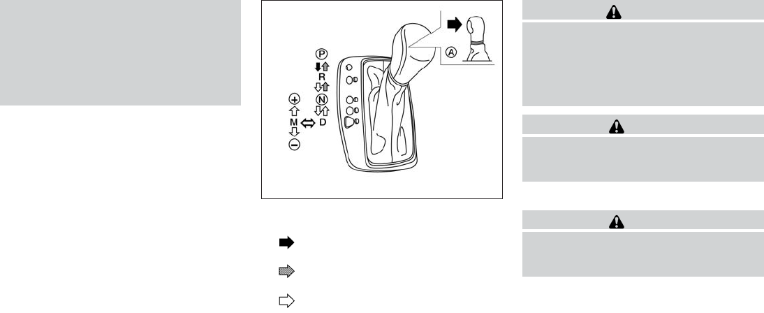
●Do not downshift abruptly on slippery
roads. This may cause a loss of control.
●Except in an emergency, do not shift to
the N (Neutral) position while driving.
Coasting with the transmission in the N
(Neutral) position may cause serious
damage to the transmission.
Shifting
Press the button 䊊
Awhile depressing the
brake pedal
Press the button 䊊
Ato shift
Shift without pressing 䊊
Abutton
After starting the engine, fully depress the brake
pedal, push and press the shift lever button and
move the shift lever from the P (Park) position to
any of the desired shift positions.
WARNING
Apply the parking brake if the shift lever is
in any position while the engine is not
running. Failure to do so could cause the
vehicle to move unexpectedly or roll away
and result in serious personal injury or
property damage.
CAUTION
Use the P (Park) or R (Reverse) position
only when the vehicle is completely
stopped.
P (Park):
CAUTION
To prevent transmission damage, use the
P (Park) or R (Reverse) position only when
the vehicle is completely stopped.
Use the P (Park) shift lever position when the
vehicle is parked or when starting the engine.
Make sure the vehicle is completely stopped.
The brake pedal must be depressed and
the shift lever button pushed in to move the
shift lever from N (Neutral) or any drive
position to P (Park). Apply the parking brake.
When parking on a hill, apply the parking brake
first, then move the shift lever into the P (Park)
position.
LSD2019
5-18 Starting and driving

R (Reverse):
CAUTION
To prevent transmission damage, use the
P (Park) or R (Reverse) position only when
the vehicle is completely stopped.
Use the R (Reverse) position to back up. Make
sure the vehicle is completely stopped before
selecting the R (Reverse) position. The brake
pedal must be depressed and the shift lever
button pushed in to move the shift lever
from P (Park), N (Neutral) or any drive po-
sition to R (Reverse).
N (Neutral):
Neither forward nor reverse gear is engaged. The
engine can be started in this position. You may
shift to N (Neutral) and restart a stalled engine
while the vehicle is moving.
D (Drive):
Use this position for all normal forward driving.
Manual shift mode
When the shift lever is in the manual shift gate,
the transmission is ready for the manual shift
mode. Shift ranges can be selected manually by
moving the shift lever up or down. To cancel
manual shift mode, return the shift lever to the D
(Drive) position. The transmission returns to au-
tomatic driving mode.
When the shift lever is shifted from D (Drive) to
the manual shift gate with the vehicle stopped or
while driving, the transmission enters the manual
shift mode. Shift ranges can be selected manu-
ally. In the manual shift mode, the shift range is
displayed on the position indicator in the meter.
When shifting the shift lever to the manual shift
gate, the position indicator displays 1 (first) up to
7 (seventh) depending on vehicle speed.
Shift ranges up or down one by one as follows:
1⇔2⇔3⇔4⇔5⇔6⇔7
7 (7th):
Use this position for all normal forward driving at
highway speeds.
5 (5th) and 6 (6th):
Use this position when driving up long slopes, or
for engine braking when driving down long
slopes.
4 (4th), 3 (3rd) and 2 (2nd):
Use these positions for hill climbing or engine
braking on downhill grades.
1 (1st)
Use this position when climbing steep hills slowly
or when driving slowly, or for maximum engine
braking on steep downhill grades.
●Remember not to drive at high speeds for
extended periods of time in lower than 7th
gear. This reduces fuel economy.
When shifting up:
Move the shift lever to the + (up) side. (Shifts to
higher range.)
When shifting down:
Move the shift lever to the ⫺(down) side. (Shifts
to lower range.)
●The transmission will automatically down-
shift the gears. (For example, if you select the
3rd range, the transmission will shift down
between the 3rd and 1st gears.)
●Moving the shift lever rapidly to the same
side twice will shift the ranges in succession.
When canceling the manual shift mode:
Return the shift lever to the D (Drive) position to
return the transmission to the normal driving
mode.
Starting and driving 5-19
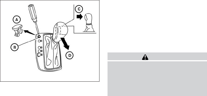
●In the manual shift mode, the transmis-
sion may not shift to the selected gear.
This helps maintain driving perfor-
mance and reduces the chance of ve-
hicle damage or loss of control.
●When this situation occurs, the Con-
tinuously Variable Transmission (CVT)
position indicator light will blink and
the chime will sound.
●In the manual shift mode, the transmis-
sion may shift up automatically to a
higher range than selected if the en-
gine speed is too high. When the ve-
hicle speed decreases, the transmis-
sion automatically shifts down and
shifts to 1st gear before the vehicle
comes to a stop.
●CVT operation is limited to automatic drive
mode when CVT fluid temperature is ex-
tremely low even if manual shift mode is
selected. This is not a malfunction. When
CVT fluid warms up, manual mode can be
selected.
●When the CVT fluid temperature is high, the
shift range may upshift in lower rpm than
usual. This is not a malfunction.
Shift lock release
If the battery charge is low or discharged, the
shift lever may not be moved from the P (Park)
position even with the brake pedal depressed
and the shift lever button pushed. To move the
shift lever, perform the following procedure:
1. Push the ignition switch to the OFF or LOCK
position.
2. Apply the parking brake.
3. Remove the shift lock release cover 䊊
Aus-
ing a suitable tool.
4. Push down the shift lock release 䊊
Busing a
suitable tool.
5. Press the shift lever button 䊊
Cand move the
shift lever to the N (Neutral) position 䊊
D
while holding down the shift lock release.
The vehicle may be moved to the desired
location. Replace the removed shift lock re-
lease cover after the operation. If the shift
lever cannot be moved out of the P (Park)
position, have an INFINITI retailer check the
CVT system as soon as possible.
WARNING
If the shift lever cannot be moved from the
P (Park) position while the engine is run-
ning and the brake pedal is depressed, the
stop lights may not work. Malfunctioning
stop lights could cause an accident injur-
ing yourself and others.
Accelerator downshift
— in D position —
For passing or hill climbing, depress the accel-
erator pedal to the floor. This shifts the transmis-
sion down into a lower gear, depending on the
vehicle speed.
LSD2022
5-20 Starting and driving

●On roads where there are sharply contrast-
ing objects, such as shadows, snow, water,
wheel ruts, seams or lines remaining after
road repairs. (The LDW system could detect
these items as lane markers.)
●On roads where the traveling lane merges or
separates.
●When the vehicle’s traveling direction does
not align with the lane marker.
●When traveling close to the vehicle in front of
you, which obstructs the lane camera unit
detection range.
●When rain, snow, dirt or object adheres to
the windshield in front of the lane camera
unit.
●When the headlights are not bright due to
dirt on the lens or if the aiming is not adjusted
properly.
●When strong light enters the lane camera
unit. (For example, the light directly shines on
the front of the vehicle at sunrise or sunset.)
●When a sudden change in brightness oc-
curs. (For example, when the vehicle enters
or exits a tunnel or under a bridge.)
LDW system operation
The LDW system provides a lane departure
warning function when the vehicle is driven at
speeds of approximately 45 MPH (70 km/h) and
above and the lane markings are clear. When the
vehicle approaches either the left or the right side
of the traveling lane, a warning chime will sound
and the Lane Departure Warning indicator light
on the instrument panel will blink to alert the
driver.
The warning function will stop when the vehicle
returns inside of the lane markers.
The LDW system is not designed to warn under
the following conditions.
●When you operate the lane change signal
and change traveling lanes in the direction of
the signal. (The LDW system will become
operable again approximately 2 seconds af-
ter the lane change signal is turned off.)
●When the vehicle speed lowers to less than
approximately 45 MPH (70 km/h).
●When the Blind Spot Intervention™ system
activates an audible warning or when the
brakes are automatically applied by the sys-
tem.
After the above conditions have finished and the
necessary operating conditions are satisfied, the
LDW functions will resume.
How to enable/disable the LDW system
Perform the following steps to enable or disable
the LDW system.
1. Press the button until “Settings” dis-
plays in the vehicle information display. Use
the to select “Driver Assistance”.
Then press the ENTER button.
2. Select “Driver Aids”, and press the ENTER
button.
Lane Departure Warning indicator light
LSD2040
Starting and driving 5-27

3. To set the LDW system to on or off, use
the buttons to navigate in the menu
and use the ENTER button to select or
change an item:
●Select “Lane” and press the ENTER but-
ton.
– To turn on the warning, use the ENTER
button to check box for “Warning (LDW)”
– To turn on the assistance system, use the
ENTER button to check box for “Assis-
tance (LDP)”
Temporary disabled status at high
temperature
If the vehicle is parked in direct sunlight under
high temperature conditions (over approximately
104°F (40°C) and then started, the LDW system
may be deactivated automatically, the warning
systems ON indicator on the switch will flash and
the following message will appear in the vehicle
information display. - “Unavailable High Cabin
Temp. ”
When the interior temperature is reduced, the
LDW system will resume operating automatically
and the warning systems ON indicator will stop
flashing.
LANE DEPARTURE PREVENTION
(LDP) SYSTEM
Precautions on LDP system
WARNING
●The LDP system will not steer the ve-
hicle or prevent loss of control. It is the
driver’s responsibility to stay alert, drive
safely, keep the vehicle in the traveling
lane, and be in control of vehicle at all
times.
●The LDP system is primarily intended
for use on well-developed freeways or
highways. It may not detect the lane
markers in certain roads, weather or
driving conditions.
●Using the LDP system under some con-
ditions of road, lane marker or weather,
or when you change lanes without us-
ing the lane change signal could lead to
an unexpected system operation. In
such conditions, you need to correct the
vehicle’s direction with your steering
operation to avoid accidents.
●When the LDP system is operating,
avoid excessive or sudden steering ma-
neuvers. Otherwise, you could lose con-
trol of the vehicle.
●The LDP system will not operate at
speeds below approximately 45 MPH
(70 km/h) or if it cannot detect lane
markers.
●Do not use the LDP system under the
following conditions as it may not func-
tion properly:
– During bad weather (rain, fog, snow,
wind, etc.).
– When driving on slippery roads, such
as on ice or snow, etc.
– When driving on winding or uneven
roads.
– When there is a lane closure due to
road repairs.
– When driving in a makeshift or tem-
porary lane.
– When driving on roads where the
lane width is too narrow.
5-28 Starting and driving

– When driving without normal tire
conditions (for example, tire wear,
low tire pressure, installation of
spare tire, tire chains, non-standard
wheels).
– When the vehicle is equipped with
nonoriginal brake parts or suspen-
sion parts.
– When you are towing a trailer or
other vehicle.
●If the LDP system malfunctions, it will
cancel automatically. The LDP system
warning light (orange) will illuminate in
the display.
●If LDP system warning light (orange)
illuminates in the display, pull off the
road to a safe location and stop the
vehicle. Turn the engine off and restart
the engine. If the LDP system warning
light (orange) continues to illuminate,
have the LDP system checked by an
INFINITI retailer.
●Excessive noise will interfere with the
warning chime sound, and the chime
may not be heard.
The functions of the LDP system (warning and
system application of the brakes) may or may not
operate properly under the following conditions:
●On roads where there are multiple parallel
lane markers; lane markers that are faded or
not painted clearly; yellow painted lane
markers; non-standard lane markers; or lane
markers covered with water, dirt, snow, etc.
●On roads where discontinued lane markers
are still detectable.
●On roads where there are sharp curves.
●On roads where there are sharply contrast-
ing objects, such as shadows, snow, water,
wheel ruts, seams or lines remaining after
road repairs. (The LDP system could detect
these items as lane markers.)
●On roads where the traveling lane merges or
separates.
●When the vehicle’s traveling direction does
not align with the lane marker.
●When traveling close to the vehicle in front of
you, which obstructs the lane camera unit
detection range.
●When rain, snow or dirt adheres to the wind-
shield in front of the lane camera unit.
●When the headlights are not bright due to
dirt on the lens or if the aiming is not adjusted
properly.
●When strong light enters the lane camera
unit. (For example, the light directly shines on
the front of the vehicle at sunrise or sunset.)
●When a sudden change in brightness oc-
curs. (For example, when the vehicle enters
or exits a tunnel or under a bridge.)
While the LDP system is operating, you may hear
a sound of brake operation. This is normal and
indicates that the LDP system is operating prop-
erly.
Starting and driving 5-29
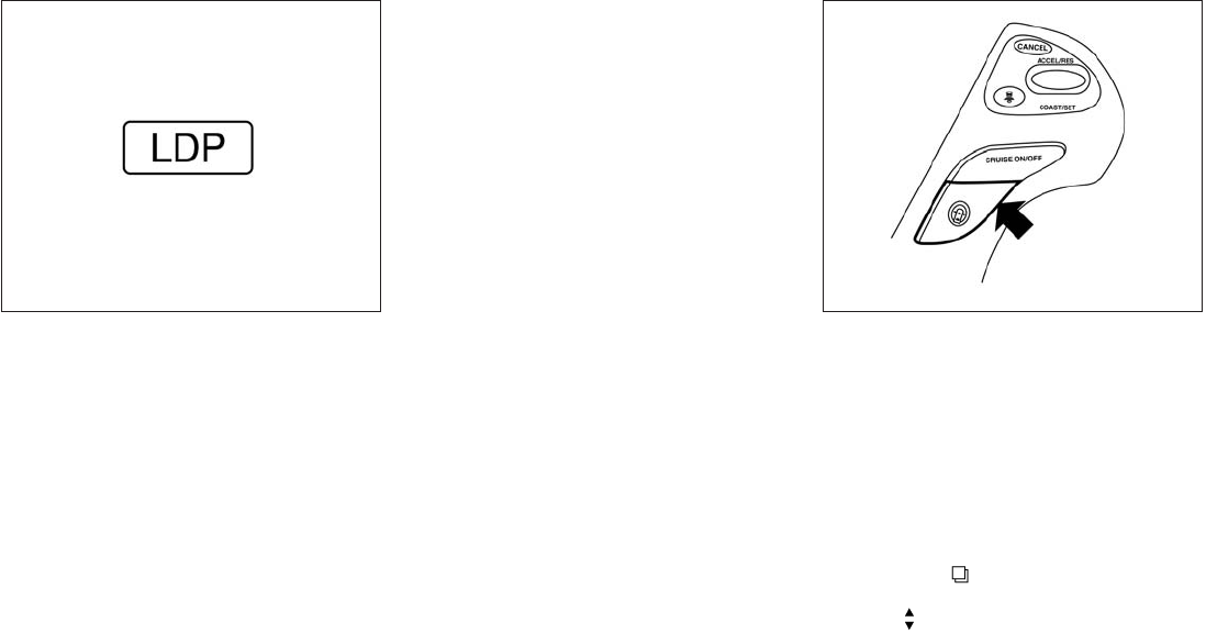
LDP system operation
The LDP system provides a lane departure warn-
ing and can automatically apply the brakes when
the vehicle is driven at speeds of approximately
45 MPH (70 km/h) and above. When the vehicle
approaches either the left or the right side of the
traveling lane, a warning chime will sound and the
LDW indicator light (orange) on the instrument
panel will blink to alert the driver. Then, the LDP
system will automatically apply the brakes for a
short period of time to help assist the driver to
return the vehicle to the center of the traveling
lane.
The warning and assist functions will stop when
the vehicle returns to a position inside of the lane
marker.
To turn on the LDP system, push the dynamic
driver assistance switch on the steering wheel
after starting the engine. The LDW indicator light
(green) on the instrument panel will illuminate.
Push the dynamic driver assistance switch again
to turn off the LDP system. The LDP/Warning
indicator light will turn off.
How to enable/disable the LDP system
Perform the following steps to enable or disable
the LDP system.
1. Press the button until “Settings” dis-
plays in the vehicle information display. Use
the to select “Driver Assistance”.
Then press the ENTER button.
LDP ON indicator light/Warning light (orange)
LSD2041
Dynamic driver assistance switch
LSD2039
5-30 Starting and driving

2. Select “Driver Aids”, and press the ENTER
button.
3. To set the LDP system to on or off, use
the buttons to navigate in the menu
and use the ENTER button to select or
change an item:
●Select “Lane” and press the ENTER but-
ton.
– To turn on the warning, use the ENTER
button to check box for Warning (LDW)”
– To turn on the assistance system, use the
ENTER button to check box for “Assis-
tance (LDP)”
Automatic deactivation
Condition A:
The warning and assist functions of the LDP
system are not designed to work under the fol-
lowing conditions:
●When you operate the lane change signal
and change the traveling lanes in the direc-
tion of the signal. (The LDP system will be
deactivated for approximately 2 seconds af-
ter the lane change signal is turned off.)
●When the vehicle speed lowers to less than
approximately 45 MPH (70 km/h).
After the above conditions have finished and the
necessary operating conditions are satisfied, the
warning and assist functions will resume.
Condition B:
The assist function of the LDP system is not
designed to work under the following conditions
(warning is still functional):
●When the brake pedal is depressed.
●When the steering wheel is turned as far as
necessary for the vehicle to change lanes.
●When the accelerator pedal is applied dur-
ing LDP system operation.
●When the Intelligent Cruise Control (ICC)
approach warning occurs.
●When the hazard warning flashers are oper-
ated.
●When driving on a curve at high speed.
After the above conditions have finished and the
necessary operating conditions are satisfied, the
LDP system application of the brakes will resume.
Condition C:
If the following messages appear in the vehicle
information display, a chime will sound and the
LDP system will be turned off automatically.
●“Unavailable Road is slippery”:
When the VDC system (except TCS func-
tion) or ABS operates.
●“Unavailable VDC OFF”:
When the VDC system is turned off.
●“Unavailable Snow mode active”:
When the drive mode select switch is turned
to the SNOW mode.
Action to take:
When the above conditions no longer exist, turn
off the LDP system. Push the dynamic driver
assistance switch again to turn the LDP system
back on.
Temporary disabled status at high tem-
perature:
If the vehicle is parked in direct sunlight under
high temperature conditions (over approximately
104°F (40°C)) and then the LDP system is turned
on, the LDP system may be deactivated auto-
matically and the following message will appear
on the vehicle information display.
“Unavailable High Cabin Temp. ”
When the interior temperature is reduced, the
system will resume operating automatically.
Starting and driving 5-31

2. Select “Back-up Collision Interv.”, and press
the ENTER button.
3. To set the BCI system to on or off, use the
buttons to navigate in the menu and use the
ENTER button to select or change an item.
BCI temporarily not available
If the following messages appear on the vehicle
information display, a chime will sound and the
BCI system will be turned off automatically.
●“Unavailable High Accelerator Temp. ” :
If the vehicle is parked in direct sunlight
under high temperature conditions (over ap-
proximately 104°F (40°C) and then started,
the BCI system may be deactivated auto-
matically and the “Unavailable High Accel-
erator Temp” message will appear in the
vehicle information display for a period of
time.
When the interior temperature is reduced,
turn off the BCI system and turn it on again.
●“Unavailable Side Radar Obstruction” :
When side radar blockage is detected.
When the blockage is removed, turn off the
BCI system and turn it on again.
BCI malfunction
If the BCI system malfunctions, it will turn off
automatically, a chime will sound and the BCI
system warning light (orange) will illuminate.
Action to take:
Stop the vehicle in a safe location, turn the engine
off and restart the engine. If the warning light
(orange) continues to illuminate, have the system
checked by an INFINITI retailer.
LSD2046
Starting and driving 5-49

RADAR MAINTENANCE
The two radar sensors 䊊
1for the BSW, BSI and
BCI systems are located near the rear bumper.
Always keep the area near the radar sensors
clean.
The radar sensors may be blocked by temporary
ambient conditions such as splashing water, mist
or fog.
The blocked condition may also be caused by
objects such as ice, frost or dirt obstructing the
radar sensors.
Check for and remove objects obstructing the
area around the radar sensors.
Do not attach stickers (including transparent ma-
terial), install accessories or apply additional
paint near the radar sensors.
Do not strike or damage the area around the
radar sensors. Consult an INFINITI retailer if the
area around the radar sensors is damaged due to
a collision.
Lane camera maintenance
For information of camera maintenance, see
“Lane camera unit maintenance” in this section.
Sonar sensor maintenance
For information of sonar sensor maintenance, see
“Sensor maintenance” in this section.
Radio frequency statement
This device complies with part 15 of the FCC
Rules and RSS-310 of Industry Canada.
Operation is subject to the following two condi-
tions:
1. This device may not cause harmful interfer-
ence.
2. This device must accept any interference
received, including interference that may
cause undesired operation.
Frequency of operation: 24.05GHz — 24.25GHz
Field Strength: Not greater than 2.5V/m peak
(0.25V/m average) at a distance of 3 m.
The manufacturer is not responsible for any radio
or TV interference caused by unauthorized modi-
fications to this equipment. Such modifications
could void the user’s authority to operate the
equipment.
LSD2025
5-50 Starting and driving
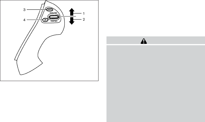
PRECAUTIONS ON CRUISE
CONTROL
1. ACCEL/RES switch
2. COAST/SET switch
3. CANCEL switch
4. ON·OFF switch
●If the cruise control system malfunctions, it
will cancel automatically. The SET indicator
in the vehicle information display will blink to
warn the driver.
●If the engine coolant temperature becomes
excessively high, the cruise control system
will be canceled automatically.
●If the SET indicator blinks, turn the cruise
control main switch off and have the system
checked by your INFINITI retailer.
●The SET indicator may sometimes blink
when the cruise control main switch is
turned ON while pushing the ACCEL/RES,
COAST/SET or CANCEL switch. To prop-
erly set the cruise control system, perform
the steps below in the order indicated.
WARNING
Do not use the cruise control when driving
under the following conditions:
●when it is not possible to keep the ve-
hicle at a set speed
●in heavy traffic or in traffic that varies in
speed
●on winding or hilly roads
●on slippery roads (rain, snow, ice, etc.)
●in very windy areas
Doing so could cause a loss of vehicle
control and result in an accident.
CRUISE CONTROL OPERATIONS
The cruise control allows driving at a speed be-
tween 25 - 89 MPH (40 - 144 km/h) without
keeping your foot on the accelerator pedal.
To turn on the cruise control, push the
ON·OFF switch on. The CRUISE indicator light in
the vehicle information display will illuminate.
SSD0941
CRUISE CONTROL (if so equipped)
Starting and driving 5-51
To set cruising speed, accelerate the vehicle to
the desired speed, push the COAST/SET switch
and release it. The SET indicator light in the
vehicle information display will illuminate. Take
your foot off the accelerator pedal. Your vehicle
maintains the set speed.
●To pass another vehicle, depress the ac-
celerator pedal. When you release the
pedal, the vehicle returns to the previously
set speed.
●The vehicle may not maintain the set speed
when going up or down steep hills. If this
happens, drive without the cruise control.
To cancel the preset speed, use one of the
following three methods.
●Push the CANCEL button; the SET indicator
light in the vehicle information display goes
out.
●Tap the brake pedal; the SET indicator light
goes out.
●Push the ON·OFF switch off. Both the
CRUISE indicator light and SET indicator
light in the vehicle information display go out.
The cruise control is automatically canceled and
the SET light in the vehicle information display
goes out if:
●you depress the brake pedal while pushing
the ACCEL/RES or SET/COAST switch.
The preset speed is deleted from memory.
●the vehicle slows down more than 8 MPH
(13 km/h) below the set speed.
●you move the shift lever to N (Neutral).
To reset at a faster cruising speed, use one of
the following three methods.
●Depress the accelerator pedal. When the
vehicle attains the desired speed, push and
release the COAST/SET switch.
●Push and hold the ACCEL/RES switch.
When the vehicle attains the speed you de-
sire, release the switch.
●Push and release the ACCEL/RES switch.
Each time you do this, the set speed in-
creases by about 1 MPH (1.6 km/h).
To reset at a slower cruising speed, use one
of the following three methods.
●Lightly tap the brake pedal. When the ve-
hicle attains the desired speed, push the
COAST/SET switch and release it.
●Push and hold the COAST/SET switch. Re-
lease the switch when the vehicle slows to
the desired speed.
●Push and release the COAST/SET switch.
Each time you do this, the set speed de-
creases by about 1 MPH (1.6 km/h).
To resume the preset speed, push and re-
lease the ACCEL/RES switch. The vehicle re-
turns to the last set cruising speed when the
vehicle speed is over 25 MPH (40 km/h).
5-52 Starting and driving

The Intelligent Cruise Control (ICC) system
maintains a selected distance from the vehicle in
front of you within the speed range of 0 to
90 MPH (0 to 144 km/h) up to the set speed. The
set speed can be selected by the driver between
20 to 90 MPH (32 to 144 km/h).
The vehicle travels at a set speed when the road
ahead is clear.
The ICC system can be set to one of two cruise
control modes.
●Vehicle-to-vehicle distance control mode:
For maintaining a selected distance be-
tween your vehicle and the vehicle in front of
you up to the preset speed.
●Conventional (fixed speed) cruise control
mode:
For cruising at a preset speed.
WARNING
●ICC is not a collision avoidance or warn-
ing device. For highway use only and
not intended for congested areas or city
driving. Will not brake automatically to
a stop. Failure to apply the brakes could
result in an accident.
●Always observe posted speed limits
and do not set the speed over them.
●Always drive carefully and attentively
when using either cruise control mode.
Read and understand the Owner’s
Manual thoroughly before using the
cruise control. To avoid serious injury or
death, do not rely on the system to pre-
vent accidents or to control the vehicle’s
speed in emergency situations. Do not
use cruise control except in appropriate
road and traffic conditions.
●In the conventional (fixed speed) cruise
control mode, a warning chime will not
sound to warn you if you are too close
to the vehicle ahead. Pay special atten-
tion to the distance between your ve-
hicle and the vehicle ahead of you or a
collision could occur.
INTELLIGENT CRUISE CONTROL (ICC)
SYSTEM (Full Speed Range) (if so
equipped)
Starting and driving 5-53

When driving on some roads, such as winding,
hilly, curved, narrow roads, or roads which are
under construction, the sensor may detect ve-
hicles in a different lane, or may temporarily not
detect a vehicle traveling ahead. This may cause
the system to work inappropriately.
The detection of vehicles may also be affected by
vehicle operation (steering maneuver or traveling
position in the lane, etc.) or vehicle condition. If
this occurs, the system may warn you by
blinking the system indicator and sounding
the chime unexpectedly. You will have to
manually control the proper distance away
from the vehicle traveling ahead.
Distance control assist system display
and indicators
The display is located between the speedometer
and tachometer.
1. Distance Control Assist (DCA) system
switch indicator:
Indicates that the dynamic driver assistance
switch is ON.
DCA Detection Zones On Winding Roads
SSD0253
DCA Indicators
LSD2068
5-76 Starting and driving
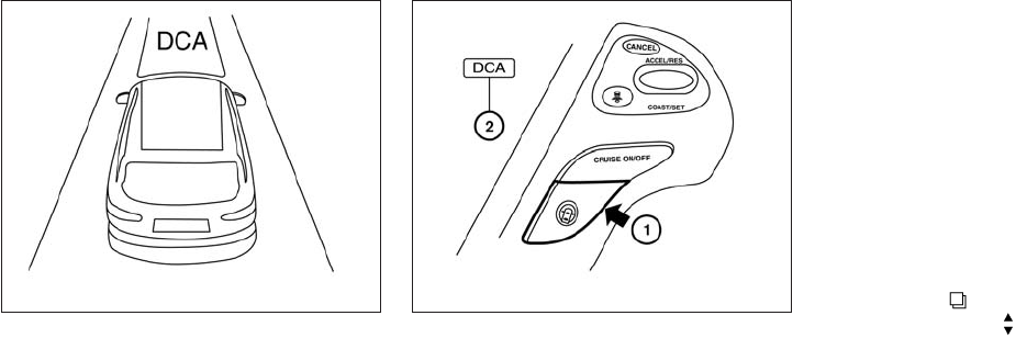
2. Vehicle ahead detection indicator:
Indicates whether it detects a vehicle in front
of you.
To turn on the DCA system, push the dynamic
driver assistance switch 䊊
1on the steering wheel
after starting the engine. The Distance Control
Assist (DCA) system switch indicator light 䊊
2in
the vehicle information display will illuminate.
Push the dynamic driver assistance switch again
to turn off the DCA system. The Distance Control
Assist (DCA) system switch indicator light will
turn off.
The system will start to operate after the vehicle
speed becomes above approximately 3 MPH
(5 km/h).
The dynamic driver assistance switch is used for
the LDP, DCA and BCI systems. When the dy-
namic driver assistance switch is pushed, the
LDP system will also turn on or off simultaneously.
The DCA system can be individually set to on or
off on the display. If the system is set to off, the
system will not turn on even if the dynamic driver
assistance switch is pushed to on. To set the
system to on or off on the display, see “Setting
DCA system to ON/OFF” in this section.
Setting DCA system to ON/OFF:
The DCA can be turned on/off in the vehicle
information display using the buttons on the
steering wheel.
1. Press the button, and select the “Set-
tings” using the . Then press the EN-
TER button.
2. Select the “Driver Aids”, and press the EN-
TER button.
3. Select “Forward”, and press the ENTER but-
ton.
4. To turn on the “Assistance (DCA)” check the
box using the ENTER button.
If the LDP, BSI and DCA systems are set to OFF
on the information display and the dynamic driver
assistance switch is pushed, the LDP ON indica-
tor light, BSI ON indicator light, and the Distance
Control Assist (DCA) system switch indicator
light will blink for approximately 2 seconds.
LSD2077 LSD2069
Starting and driving 5-77

For additional information on LDP and BSI, see
“Lane Departure Warning (LDW) system/Lane
Departure Prevention (LDP) system and Blind
Spot Warning/Blind Spot Intervention” in this
section.
Under the following conditions, the Distance
Control Assist system will not operate and the
DCA cancellation message will pop up:
●When the SNOW mode switch is ON (To
use the DCA system, turn off the SNOW
mode switch, then turn on the dynamic driver
assistance switch.)
For details about the SNOW mode switch,
see “Snow mode switch” in this section.
●When the VDC system is off (To use the
DCA system, turn on the VDC, then push the
dynamic driver assistance switch.)
For details about the VDC system, see “Ve-
hicle Dynamic Control (VDC) system” in this
section.
●When ABS or VDC (including the traction
control system) is operating
When the Conventional (fixed speed) cruise con-
trol mode is operating, the DCA system will not
operate. (To use the DCA system, turn the Con-
ventional (fixed speed) cruise control mode off,
then push the dynamic driver assistance switch.)
For details about the Conventional (fixed speed)
cruise control mode, see “Intelligent Cruise Con-
trol (ICC) system “Full speed range” in this sec-
tion.
When the engine is turned off, the system is
automatically turned off.
䊊
1System set display with vehicle ahead
䊊
2System set display without vehicle ahead
LSD2126
5-78 Starting and driving

Approach warning
If your vehicle comes closer to the vehicle ahead
due to rapid deceleration of that vehicle or if
another vehicle cuts in, the system warns the
driver with the chime and DCA system display.
Decelerate by depressing the brake pedal to
maintain a safe vehicle distance if:
●The chime sounds.
●The vehicle ahead detection indicator blinks.
The warning chime may not sound in some cases
when there is a short distance between vehicles.
Some examples are:
●When the vehicles are traveling at the same
speed and the distance between vehicles is
not changing
●When the vehicle ahead is traveling faster
and the distance between vehicles is in-
creasing
●When a vehicle cuts in near your vehicle
The warning chime will not sound when your
vehicle approaches vehicles that are parked or
moving slowly.
NOTE:
The approach warning chime may sound
and the system display may blink when ICC
sensor detects vehicles in other lanes 䊊
Aor
objects on the side of the road 䊊
A. This may
cause the DCA system to operate inappro-
priately. The ICC sensor may detect these
objects when the vehicle is driven on wind-
ing roads, narrow roads, hilly roads or when
entering or exiting a curve. In these cases
you will have to manually control the
proper distance ahead of your vehicle.
Also, the sensor sensitivity can be affected by
vehicle operation (steering maneuver or driving
position in the lane) or traffic or vehicle condition
(for example, if a vehicle is being driven with some
damage).
Automatic cancellation
Condition A:
Under the following conditions, the Distance
Control Assist system is automatically canceled.
The chime will sound and the Distance Control
Assist (DCA) cancellation message will pop up.
SSD0284A
5-80 Starting and driving
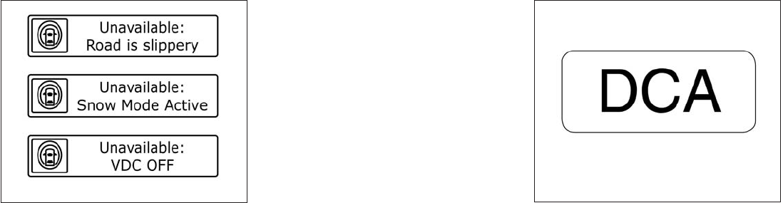
●When the VDC system is turned off
●When the VDC or ABS (including the trac-
tion control system) operates
●When the SNOW mode switch is turned
ON
Action to take:
When the conditions listed above are no longer
present, turn the system off with the dynamic
driver assistance switch. Turn the DCA system
back on to use the system.
Condition B:
When the sensor area of the front bumper is dirty,
making it impossible to detect a vehicle ahead,
the DCA system is automatically canceled.
The chime sounds and the system warning light
(orange) will come on and the “Sensor Blocked”
indicator will appear.
Action to take:
If the warning light comes on, park the vehicle in a
safe place, turn the engine off. Clean the sensor
area of the bumper and then perform the settings
again.
Condition C:
When the DCA system is not operating properly,
the chime sounds and the system warning light
(“DCA” orange) will come on.
Action to take:
If the warning light comes on, park the vehicle in a
safe place. Turn the engine off, restart the engine,
and turn on the DCA system again.
LSD2080
DCA warning light (orange)
LSD2081
Starting and driving 5-81

If it is not possible to set the system or the
indicator stays on, it may indicate that the
system is malfunctioning. Although the ve-
hicle is still driveable under normal condi-
tions, have the vehicle checked at an
INFINITI retailer.
Sensor maintenance
How to handle the sensor:
The sensor for the DCA system is common with
Intelligent Cruise Control and is located behind
the front bumper.
To handle the sensor, see “Intelligent Cruise
Control (ICC) system (Full speed range)” in this
section.
The Forward Collision Warning (FCW) system
will warn the driver by a warning light and chime
when your vehicle is getting close to the vehicle
ahead in the traveling lane.
The FCW system will function when your vehicle
is driven at speeds of approximately 10 MPH
(15 km/h) and above.
The FCW system uses the distance sensor 䊊
A
located behind the front bumper to measure the
distance to the vehicle ahead. When the system
judges that your vehicle is getting close to the
vehicle ahead in the travel lane, the vehicle ahead
detection indicator light on the instrument panel
blinks and a warning chime sounds.
The FCW system can be turned on/off by push-
ing the warning systems switch. The warning
systems ON indicator light 䊊
1on the switch will
illuminate when the system is ON.
LSD2098
FORWARD COLLISION WARNING
(FCW) SYSTEM (if so equipped)
5-82 Starting and driving
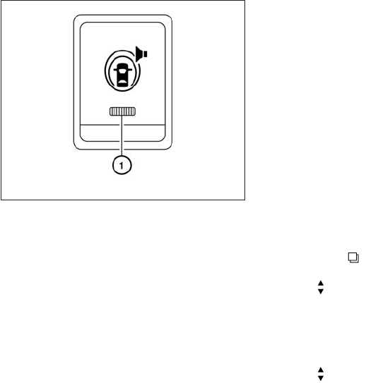
FCW SYSTEM OPERATION
The FCW system is active at speeds of approxi-
mately 10 MPH (15 km/h) and above, when the
system turns on.
The warning systems switch is used to turn on
and off the FCW system when it is activated
using the settings menu on the information dis-
play. See “How to enable/disable the FCW sys-
tem” using the settings menu later in this section.
When the warning systems switch is turned off,
the indicator 䊊
1on the switch is off. The indicator
will also be off if the FCW, the Lane Departure
Warning (LDW) and the Blind Spot Warning
(BSW) systems are deactivated.
When the warning systems switch is pushed, the
LDW and BSW system will also turn on or off
simultaneously. See “Lane Departure Warning
(LDW) system/Lane Departure Prevention (LDP)
system” and “Blind Spot Warning (BSW)/Blind
Spot Intervention (BSI)/Back-up Collision Inter-
vention (BCI) systems” in this section.
For the sensor maintenance, see “Intelligent
Cruise Control (ICC) system” in this section.
How to enable/disable the FCW
system
Perform the following steps to enable or disable
the FCW system.
1. Press the button until “Settings” dis-
plays in the vehicle information display. Use
the to select “Driver Assistance”.
Then press the ENTER button.
2. Select “Driver Aids”, and press the ENTER
button.
3. To set the DCA system to on or off, use
the buttons to navigate in the menu
and use the ENTER button to select or
change an item:
●Select “Forward” and press the ENTER
button.
– To turn on the warning, use the ENTER
button to check box for “Warning (FCW)”
– To turn on the system, use the ENTER
button to check box for “Assistance
(DCA)”
Warning systems switch
LSD2015
Starting and driving 5-85

– Pedestrians, animals or obstacles in
the roadway
– Oncoming vehicles in the same lane
●The sensor generally detects the sig-
nals returned from the vehicle ahead.
Therefore, the system may not function
properly under the following
conditions:
– When the sensor area of the front
bumper gets dirty and it is impos-
sible to detect the distance from the
vehicle ahead.
– When radar signal is temporarily
interrupted.
– When visibility is low (such as rain,
fog, snow, etc.).
– When snow or road spray from trav-
eling vehicles is splashed.
– When excessively heavy baggage is
loaded in the rear seat or the luggage
room of your vehicle.
– When abruptly accelerating or
decelerating.
– On a steep downhill slope or on
roads with sharp curves.
– When there is a highly reflective ob-
ject near the vehicle ahead (for ex-
ample, being very close to another
vehicle, signboard, etc.)
– When you are towing a trailer.
●Depending on certain road conditions
(curved or beginning of a curve), vehicle
conditions (steering position or vehicle
position), or the preceding vehicle’s
conditions (position in lane, etc.), the
system may not function properly. The
system may detect objects such as
signs and other stationary objects on
the road or near the traveling lane and
provide unnecessary warning.
●The system may not function in offset
conditions. WARNING
●In extreme conditions, detection of
these objects may cause the system to
function.
Reflectors on the road
LSD2021
Starting and driving 5-87

●The system is designed to automatically
check the sensor’s functionality. When
the sensor detects an obstruction of the
radar signals due to dirt, adhesive ma-
terial, or similar objects to the front
bumper, the system will automatically
cancel. However, sensor may not detect
all obstructive material. In these in-
stances the system may not be able to
warn the driver properly. Be sure to
check and clean the sensor area of the
front bumper regularly.
●Excessive noise will interfere with the
warning chime sound, and the chime
may not be heard.
●A sudden appearance of a vehicle in
front (for example, it abruptly cuts in)
may not be detected and the system
may not warn the driver soon enough.
●The system will be cancelled automati-
cally with a beep sound and the IBA
warning light will illuminate under the
following conditions:
– When the sensor area of the front
bumper is dirty
– When the system malfunctions
If the IBA OFF indicator light illuminates with a
beep sound, pull off the road to a safe location,
stop the vehicle and turn the engine off. Check to
see if the sensor area of the front bumper is dirty.
If the sensor area of the front bumper is dirty,
clean it with a soft cloth and restart the engine. If
the sensor area of the bumper is not dirty, restart
the engine. If the IBA OFF indicator light contin-
ues to illuminate even if the IBA system is turned
on, have the system checked by an INFINITI
retailer.
IBA SYSTEM OPERATION
The IBA system will function when your vehicle is
driven at speeds of approximately 10 MPH
(15 km/h) or above, and when the vehicle’s
speed is approximately 10 MPH (15 km/h) faster
than that of the vehicle ahead.
To turn the system on/off:
1. Push the button to enter the “Set-
tings” menu in the vehicle information dis-
play, then select using the ENTER button.
2. Use the buttons to select “Driver As-
sistance”, then press the ENTER button.
3. Use the buttons to select “Intelligent
Brake Assist”, using the ENTER button the
system can be turned On or Off.
The IBA system will remain in the last ON or OFF
state it was left in until it is changed in the vehicle
information display, see “Driver Assistance” in the
“Instrument and controls” section.
Illumination of the IBA OFF indicator light without
the warning chime sound is an indication that the
IBA system is temporarily unavailable. It will occur
under the following conditions:
When the radar signal is temporarily interrupted.
The IBA OFF indicator light will turn off when the
system returns to its normal operating conditions.
For the sensor maintenance, see “Intelligent
Cruise Control (ICC) system (Full speed range)”.
5-88 Starting and driving
7. Avoid Idling
●Shutting off your engine when safe for
stops exceeding 30–60 seconds saves
fuel and reduces emissions
8. Buy an Automated Pass for Toll Roads
●Automated passes permit drivers to use
special lanes to maintain cruising speed
through the toll and avoid stopping and
starting
9. Winter Warm Up
●Limit idling time to minimize impact to fuel
economy
●Vehicles typically need no more than
30 seconds of idling at start-up to effec-
tively circulate the engine oil before driv-
ing
●Your vehicle will reach its ideal operating
temperature more quickly while driving
versus idling
10. Keeping your Vehicle Cool
●Park your vehicle in a covered parking
area or in the shade whenever possible
●When entering a hot vehicle, opening the
windows will help to reduce the inside
temperature faster, resulting in reduced
demand on your A/C system
●Keep your engine tuned up.
●Follow the recommended scheduled main-
tenance.
●Keep the tires inflated to the correct pres-
sure. Low tire pressure increases tire wear
and lowers fuel economy.
●Keep the front wheels in correct alignment.
Improper alignment increases tire wear and
lowers fuel economy.
●Use the recommended viscosity engine oil.
See “Engine oil and oil filter recommenda-
tions” in “Technical and consumer informa-
tion” later in this manual.
If any malfunction occurs in the Intelligent AWD
system while the engine is running, messages are
displayed in the meter.
INCREASING FUEL ECONOMY INTELLIGENT ALL-WHEEL DRIVE
(AWD) (if so equipped)
5-90 Starting and driving

If the AWD error warning message is displayed,
there may be a malfunction in the Intelligent AWD
system. Reduce vehicle speed and have your
vehicle checked by an INFINITI retailer as soon as
possible.
The AWD high temperature message may be
displayed while trying to free a stuck vehicle due
to increased oil temperature. The driving mode
may change to two-wheel drive. If this message is
displayed, stop the vehicle with the engine idling,
as soon as it is safe to do so. Then if the message
turns off, you can continue driving.
The tire size message may be displayed if there is
a large difference between the diameters of front
and rear wheels. Pull off the road in a safe area,
with the engine idling. Check that all tire sizes are
the same, that the tire pressure is correct and that
the tires are not excessively worn.
If any warning messages continue to be dis-
played, have your vehicle checked by an INFINITI
retailer as soon as possible.
LSD2082 LSD2083 LSD2084
Starting and driving 5-91

WARNING
●Do not drive beyond the performance
capability of the tires. Accelerating
quickly, sharp steering maneuvers or
sudden braking may cause loss of con-
trol, even with Intelligent AWD
engaged.
●For AWD equipped vehicles, do not at-
tempt to raise two wheels off the
ground and shift the transmission to
any drive or reverse position with the
engine running. Doing so may result in
drivetrain damage or unexpected ve-
hicle movement which could result in
serious personal injury or vehicle
damage.
●Do not attempt to test an AWD
equipped vehicle on a 2-wheel dyna-
mometer (such as the dynamometers
used by some states for emissions test-
ing) or similar equipment even if the
other two wheels are raised off the
ground. Make sure that you inform the
test facility personnel that your vehicle
is equipped with AWD before it is
placed on a dynamometer. Using the
wrong test equipment may result in
drivetrain damage or unexpected ve-
hicle movement which could result in
serious personal injury or vehicle
damage.
CAUTION
●Do not operate the engine on a free
roller when any of the wheels are
raised.
●If you use the free roller, rotate 4 wheels
with the same speed without raising
any wheels.
●If an AWD warning message is dis-
played while driving there may be a
malfunction in the AWD system. Reduce
the vehicle speed immediately and have
your vehicle checked by an INFINITI re-
tailer as soon as possible.
●The powertrain may be damaged if you
continue driving when the AWD tem-
perature or tire size incorrect messages
are displayed
●If the AWD high temperature message
is displayed while you are driving, pull
off the road in a safe area, and idle the
engine. The driving mode will change to
2WD to prevent the AWD system from
malfunctioning. If the warning message
turns off, you can drive again.
●If the tire size incorrect message is dis-
played while you are driving, pull off the
road in a safe area with the engine
idling. Check that all tire sizes are the
same, that the tire pressure is correct
and that the tires are not excessively
worn.
●If a warning message continues to be
displayed after the above operations,
have your vehicle checked by an
INFINITI retailer as soon as possible.
5-92 Starting and driving

WARNING
●Do not stop or park the vehicle over
flammable materials such as dry grass,
waste paper or rags. They may ignite
and cause a fire.
●Safe parking procedures require that
both the parking brake be set and the
transmission placed into P (Park). Fail-
ure to do so could cause the vehicle to
move unexpectedly or roll away and re-
sult in an accident. Make sure the shift
lever has been pushed as far forward as
it can go and cannot be moved without
depressing the foot brake pedal.
●Never leave the engine running while
the vehicle is unattended.
●Do not leave children unattended inside
the vehicle. They could unknowingly ac-
tivate switches or controls. Unattended
children could become involved in seri-
ous accidents.
1. Firmly apply the parking brake.
2. Move the shift lever to the P (Park) position.
3. To help prevent the vehicle from rolling into
traffic when parked on an incline, it is a good
practice to turn the wheels as illustrated.
●HEADED DOWNHILL WITH CURB: 䊊
A
Turn the wheels into the curb and move the
vehicle forward until the curb side wheel
gently touches the curb.
●HEADED UPHILL WITH CURB: 䊊
B
Turn the wheels away from the curb and
move the vehicle back until the curb side
wheel gently touches the curb.
●HEADED UPHILL OR DOWNHILL, NO
CURB: 䊊
C
Turn the wheels toward the side of the road
so the vehicle will move away from the cen-
ter of the road if it moves.
4. Place the ignition switch in the LOCK posi-
tion.
WSD0050
PARKING/PARKING ON HILLS
Starting and driving 5-93

WARNING
●While driving on a slippery surface, be
careful when braking, accelerating or
downshifting. Abrupt braking or accel-
erating could cause the wheels to skid
and result in an accident.
●If the engine is not running or is turned
off while driving, the power assist for
the brakes will not work. Braking will be
harder.
Wet brakes
When the vehicle is washed or driven through
water, the brakes may get wet. As a result, your
braking distance will be longer and the vehicle
may pull to one side during braking.
To dry the brakes, drive the vehicle at a safe
speed while lightly pressing the brake pedal to
heat up the brakes. Do this until the brakes return
to normal. Avoid driving the vehicle at high
speeds until the brakes function correctly.
Parking brake break-in
Break-in the parking brake shoes whenever the
effect of the parking brake is weakened or when-
ever the parking brake shoes and/or drum/rotors
are replaced, in order to assure the best brake
performance.
This procedure is described in the vehicle service
manual and can be performed by an INFINITI
retailer.
ANTI-LOCK BRAKING SYSTEM
(ABS)
WARNING
●The Anti-lock Braking System (ABS) is a
sophisticated device, but it cannot pre-
vent accidents resulting from careless
or dangerous driving techniques. It can
help maintain vehicle control during
braking on slippery surfaces. Remem-
ber that stopping distances on slippery
surfaces will be longer than on normal
surfaces even with ABS. Stopping dis-
tances may also be longer on rough,
gravel or snow covered roads, or if you
are using tire chains. Always maintain a
safe distance from the vehicle in front of
you. Ultimately, the driver is respon-
sible for safety.
●Tire type and condition may also affect
braking effectiveness.
– When replacing tires, install the
specified size of tires on all four
wheels.
– When installing a spare tire, make
sure that it is the proper size and type
as specified on the Tire and Loading
Information label. See “Tire and
Loading Information label” in the
“Technical and consumer informa-
tion” section of this manual.
– For detailed information, see
“Wheels and tires” in the “Mainte-
nance and do-it-yourself” section of
this manual.
The Anti-lock Braking System (ABS) controls the
brakes so the wheels do not lock during hard
braking or when braking on slippery surfaces.
The system detects the rotation speed at each
wheel and varies the brake fluid pressure to pre-
vent each wheel from locking and sliding. By
preventing each wheel from locking, the system
helps the driver maintain steering control and
helps to minimize swerving and spinning on slip-
pery surfaces.
Using the system
Depress the brake pedal and hold it down. De-
press the brake pedal with firm steady pressure,
but do not pump the brakes. The ABS will oper-
ate to prevent the wheels from locking up. Steer
the vehicle to avoid obstacles.
Starting and driving 5-95

●When driving on extremely inclined sur-
faces such as higher banked corners,
the VDC system may not operate prop-
erly and the indicator may flash or
both the and indicator
lights may illuminate. Do not drive on
these types of roads.
●When driving on an unstable surface
such as a turntable, ferry, elevator or
ramp, the indicator may flash or
both the and indicator
lights may illuminate. This is not a mal-
function. Restart the engine after driv-
ing onto a stable surface.
●If wheels or tires other than the INFINITI
recommended ones are used, the VDC
system may not operate properly and
the indicator may flash or both
the and indicator lights may
illuminate.
●The VDC system is not a substitute for
winter tires or tire chains on a snow
covered road.
ACTIVE TRACE CONTROL (if so
equipped)
This system senses driving based on the driver’s
steering and acceleration/braking patterns, and
controls brake pressure at individual wheels to
help smooth vehicle response.
When the VDC OFF switch is used to turn off the
VDC system, the active trace control system is
also turned off.
If the active trace control is not functioning prop-
erly, the IBA OFF indicator light illuminates in the
instrument panel.
BRAKE FORCE DISTRIBUTION
During braking while driving through turns, the
system optimizes the distribution of force to each
of the four wheels depending on the radius of the
turn.
WARNING
●The VDC system is designed to help the
driver maintain controllability but can-
not prevent accidents due to abrupt
steering operation at high speeds or by
careless or dangerous driving tech-
niques. Reduce vehicle speed and be
especially careful when driving and cor-
nering on slippery surfaces and always
drive carefully.
●The active trace control and brake force
distribution systems may not be effec-
tive depending on the driving condition.
Always drive carefully and attentively.
●Do not modify the vehicle’s suspension.
If suspension parts such as shock ab-
sorbers, struts, springs, stabilizer bars,
bushings and wheels are not INFINITI
recommended for your vehicle or are
extremely deteriorated, the VDC system
may not operate properly. This could
adversely affect vehicle handling per-
formance, and the VDC warning light
may illuminate.
5-98 Starting and driving

●If brake related parts such as brake
pads, rotors and calipers are not
INFINITI recommended or are extremely
deteriorated, the VDC system may not
operate properly and the VDC warning
light may illuminate.
●If engine control related parts are not
INFINITI recommended or are extremely
deteriorated, the VDC warning light may
illuminate.
●
When driving on extremely inclined sur-
faces such as higher banked corners, the
VDC system may not operate properly and
the VDC warning light may illuminate. Do
not drive on these types of roads.
●When driving on an unstable surface
such as a turntable, ferry, elevator or
ramp, the VDC warning light may illumi-
nate. This is not a malfunction. Restart
the engine after driving onto a stable
surface.
●If wheels or tires other than the INFINITI
recommended ones are used, the VDC
system may not operate properly and
the VDC warning light may illuminate.
●The VDC system is not a substitute for
winter tires or tire chains on a snow
covered road.
WARNING
●Never rely solely on the hill start assist
system to prevent the vehicle from mov-
ing backward on a hill. Always drive
carefully and attentively. Depress the
brake pedal when the vehicle is stopped
on a steep hill. Be especially careful
when stopped on a hill on frozen or
muddy roads. Failure to prevent the ve-
hicle from rolling backwards may result
in a loss of control of the vehicle and
possible serious injury or death.
●The hill start assist system is not de-
signed to hold the vehicle at a standstill
on a hill. Depress the brake pedal when
the vehicle is stopped on a steep hill.
Failure to do so may cause the vehicle
to roll backwards and may result in a
collision or serious personal injury.
●The hill start assist system may not pre-
vent the vehicle from rolling backwards
on a hill under all load or road condi-
tions. Always be prepared to depress
the brake pedal to prevent the vehicle
from rolling backwards. Failure to do so
may result in a collision or serious per-
sonal injury.
The hill start assist system automatically keeps
the brakes applied to help prevent the vehicle
from rolling backwards in the time it takes the
driver to release the brake pedal and apply the
accelerator when the vehicle is stopped on a hill.
The hill start assist system will operate automati-
cally under the following conditions:
●The transmission is shifted to a forward or
reverse gear.
●The vehicle is stopped completely on a hill
by applying the brake. The maximum holding
time is 2 seconds. After 2 seconds the ve-
hicle will begin to roll back and the hill start
assist system will stop operating completely.
The hill start assist system will not operate when
the shift lever is placed in the N (Neutral) or P
(Park) position or on a flat and level road.
HILL START ASSIST SYSTEM
Starting and driving 5-99

FREEING A FROZEN DOOR LOCK
To prevent a door lock from freezing, apply de-
icer through the key hole. If the lock becomes
frozen, heat the key before inserting it into the key
hole, or use the INFINITI Intelligent Key.
ANTI-FREEZE
In the winter when it is anticipated that the tem-
perature will drop below 32°F (0°C), check the
anti-freeze to assure proper winter protection.
For details, see “Engine cooling system” in the
“Maintenance and do-it-yourself” section of this
manual.
BATTERY
If the battery is not fully charged during extremely
cold weather conditions, the battery fluid may
freeze and damage the battery. To maintain maxi-
mum efficiency, the battery should be checked
regularly. For details, see “Battery” in the “Main-
tenance and do-it-yourself” section of this
manual.
DRAINING OF COOLANT WATER
If the vehicle is to be left outside without anti-
freeze, drain the cooling system, including the
engine block. Refill before operating the vehicle.
For details, see “Changing engine coolant” in the
“Maintenance and do-it-yourself” section of this
manual.
TIRE EQUIPMENT
1. SUMMER tires have a tread designed to
provide superior performance on dry pave-
ment. However, the performance of these
tires will be substantially reduced in snowy
and icy conditions. If you operate your ve-
hicle on snowy or icy roads, INFINITI recom-
mends the use of MUD & SNOW or ALL
SEASON TIRES on all four wheels. Please
consult an INFINITI retailer for the tire type,
size, speed rating and availability informa-
tion.
2. For additional traction on icy roads, studded
tires may be used. However, some U.S.
states and Canadian provinces prohibit their
use. Check local, state and provincial laws
before installing studded tires.
Skid and traction capabilities of studded
snow tires on wet or dry surfaces may be
poorer than that of non-studded snow tires.
3. Tire chains may be used. For details see
“Tire chains” in the “Maintenance and do-it-
yourself” section of this manual.
SPECIAL WINTER EQUIPMENT
It is recommended that the following items be
carried in the vehicle during winter:
●A scraper and stiff-bristled brush to remove
ice and snow from the windows and wiper
blades.
●A sturdy, flat board to be placed under the
jack to give it firm support.
●A shovel to dig the vehicle out of snowdrifts.
●Extra washer fluid to refill the windshield-
washer fluid reservoir.
DRIVING ON SNOW OR ICE
WARNING
●Wet ice (32°F, 0°C and freezing rain),
very cold snow or ice can be slick and
very hard to drive on. The vehicle will
have much less traction or “grip” under
these conditions. Try to avoid driving on
wet ice until the road is salted or
sanded.
●Whatever the condition, drive with cau-
tion. Accelerate and slow down with
care. If accelerating or downshifting too
fast, the drive wheels will lose even
more traction.
COLD WEATHER DRIVING
5-100 Starting and driving
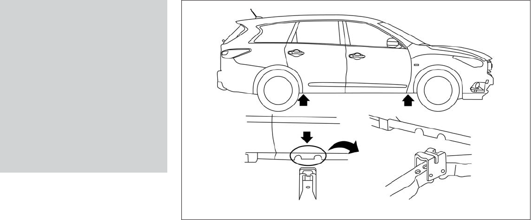
●Use the correct jack-up points. Never
use any other part of the vehicle for jack
support.
●Never jack up the vehicle more than
necessary.
●Never use blocks on or under the jack.
●Do not start or run the engine while
vehicle is on the jack. It may cause the
vehicle to move. This is especially true
for vehicles with limited slip
differentials.
●Do not allow passengers to stay in the
vehicle while it is on the jack.
●Never run the engine with a wheel(s) off
the ground. It may cause the vehicle to
move.
Always refer to the illustration for the correct
placement and jack-up points for your specific
vehicle model and jack type.
Carefully read the caution label attached to
the jack body and the following instruc-
tions.
1. Loosen each wheel nut one or two turns by
turning counterclockwise with the wheel nut
wrench. Do not remove the wheel nuts
until the tire is off the ground.
2. Place the jack directly under the jack-up
point as illustrated so the top of the jack
contacts the vehicle at the jack-up point. The
jack-up points are indicated by stamped ar-
rows on the side of the frame.
The jack should be used on firm and
level ground.
LCE2040
In case of emergency 6-7

To start your engine with a booster battery, the
instructions and precautions below must be fol-
lowed.
WARNING
●If done incorrectly, jump starting can
lead to a battery explosion, resulting in
severe injury or death. It could also
damage your vehicle.
●Explosive hydrogen gas is always pres-
ent in the vicinity of the battery. Keep all
sparks and flames away from the
battery.
●Do not allow battery fluid to come into
contact with eyes, skin, clothing or
painted surfaces. Battery fluid is a cor-
rosive sulfuric acid solution which can
cause severe burns. If the fluid should
come into contact with anything, imme-
diately flush the contacted area with
water.
●Keep battery out of the reach of
children.
●The booster battery must be rated at
12 volts. Use of an improperly rated
battery can damage your vehicle.
●Whenever working on or near a battery,
always wear suitable eye protectors (for
example, goggles or industrial safety
spectacles) and remove rings, metal
bands, or any other jewelry. Do not lean
over the battery when jump starting.
●Do not attempt to jump start a frozen
battery. It could explode and cause se-
rious injury.
●Your vehicle has an automatic engine
cooling fan. It could come on at any
time. Keep hands and other objects
away from it.
JUMP STARTING
6-10 In case of emergency

6. After the engine cools down, check the cool-
ant level in the engine coolant reservoir tank
with the engine running. Add coolant to the
engine coolant reservoir tank if necessary.
Have your vehicle repaired at an INFINITI
retailer.
When towing your vehicle, all State (Provincial in
Canada) and local regulations for towing must be
followed. Incorrect towing equipment could dam-
age your vehicle. Towing instructions are avail-
able from an INFINITI retailer. Local service op-
erators are generally familiar with the applicable
laws and procedures for towing. To assure
proper towing and to prevent accidental damage
to your vehicle, INFINITI recommends having a
service operator tow your vehicle. It is advisable
to have the service operator carefully read the
following precautions:
WARNING
●Never ride in a vehicle that is being
towed.
●Never get under your vehicle after it has
been lifted by a tow truck.
CAUTION
●When towing, make sure that the trans-
mission, axles, steering system and
powertrain are in working condition. If
any of these conditions apply, dollies or
a flatbed tow truck must be used.
●Always attach safety chains before
towing.
For information about towing your vehicle behind
a recreational vehicle (RV), refer to “Flat towing”
in the “Technical and consumer information” sec-
tion of this manual.
TOWING RECOMMENDED BY
INFINITI
TOWING YOUR VEHICLE
In case of emergency 6-13
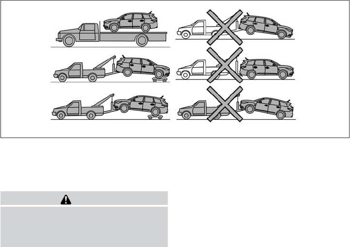
All-Wheel Drive (AWD) models
INFINITI recommends that towing dollies be used
when towing your vehicle or the vehicle be
placed on a flat bed truck as illustrated.
CAUTION
Never tow AWD models with any of the
wheels on the ground as this may cause
serious and expensive damage to the
powertrain.
LCE2042
6-14 In case of emergency

Front-Wheel Drive models
INFINITI recommends that your vehicle be towed
with the driving wheels (front) off the ground or
place the vehicle on a flat bed truck as illustrated.
WARNING
●Never tow your vehicle with the front
wheels on the ground or four wheels on
the ground (forward or backward), as
this may cause serious and expensive
damage to the transmission. If it is nec-
essary to tow the vehicle with the rear
wheels raised always use towing dollies
under the front wheels.
●When towing with the rear wheels on
the ground or on towing dollies, place
the ignition switch in the ACC or ON
position, and secure the steering wheel
in the straight-ahead position with a
rope or similar device.
VEHICLE RECOVERY (freeing a stuck
vehicle)
Pulling a stuck vehicle
WARNING
To avoid vehicle damage, serious personal
injury or death when recovering a stuck
vehicle:
●Contact a professional towing service
to recover the vehicle if you have any
questions regarding the recovery
procedure.
●Attach recovery devices only to main
structural members of the vehicle or the
recovery hooks.
●Do not use the vehicle tie-downs to tow
or free a stuck vehicle.
●Only use devices specifically designed
for vehicle recovery and follow the
manufacturer’s instructions.
●Always pull the recovery device straight
out from the front of the vehicle. Never
pull at an angle.
●Route recovery devices so they do not
touch any part of the vehicle except the
attachment point.
LCE2041
In case of emergency 6-15

If your vehicle is stuck in sand, snow, mud, etc.,
use a tow strap or other device designed specifi-
cally for vehicle recovery. Always follow the
manufacturer’s instructions for the recovery de-
vice.
Do not use the tie-down hooks for towing or
vehicle recovery.
Rocking a stuck vehicle
WARNING
●Stand clear of a stuck vehicle.
●Do not spin your tires at high speed.
This could cause them to explode and
result in serious injury. Parts of your
vehicle could also overheat and be
damaged.
If your vehicle is stuck in sand, snow, mud, etc.,
use the following procedure:
1. Turn off the Vehicle Dynamic Control System
(VDC).
2. Make sure the area in front and behind the
vehicle is clear of obstructions.
3. Turn the steering wheel right and left to clear
an area around the front tires.
4. Slowly rock the vehicle forward and back-
ward.
●Shift back and forth between R (Reverse)
and D (Drive).
●Apply the accelerator as little as possible
to maintain the rocking motion.
●Release the accelerator pedal before
shifting between R and D.
●Do not spin the tires above 35 MPH
(55 km/h).
5. If the vehicle cannot be freed after a few
tries, contact a professional towing service
to remove the vehicle.
6-16 In case of emergency

7 Appearance and care
Cleaning exterior ..................................7-2
Washing ......................................7-2
Waxing ........................................7-2
Removing spots ................................7-3
Underbody ....................................7-3
Glass .........................................7-3
Aluminum alloy wheels ..........................7-3
Chrome parts ..................................7-3
Tire dressings ..................................7-3
Cleaning interior...................................7-4
Air fresheners ..................................7-4
Moonroof ......................................7-4
Floor mats .....................................7-5
Seat belts .....................................7-6
Cleaning the seat tracks.........................7-6
Corrosion protection ...............................7-6
Most common factors contributing to vehicle
corrosion ......................................7-6
Environmental factors influence the rate of
corrosion ......................................7-6
To protect your vehicle from corrosion ............7-7
Seat belts Check that all parts of the seat belt
system (for example, buckles, anchors, adjusters
and retractors) operate properly and smoothly,
and are installed securely. Check the belt web-
bing for cuts, fraying, wear or damage.
Steering wheel Check for changes in the steer-
ing system, such as excessive freeplay, hard
steering or strange noises.
Warning lights and chimes Make sure all
warning lights and chimes are operating properly.
Windshield wiper and washer* Check that
the wipers and washer operate properly and that
the wipers do not streak.
Windshield defroster Check that the air
comes out of the defroster outlets properly and in
sufficient quantity when operating the heater or
air conditioner.
Under the hood and vehicle
The maintenance items listed here should be
checked periodically (for example, each time you
check the engine oil or refuel).
Battery* Check the fluid level in each cell. It
should be between the MAX and MIN lines. Ve-
hicles operated in high temperatures or under
severe conditions require frequent checks of the
battery fluid level.
NOTE:
Care should be taken to avoid situations that
can lead to potential battery discharge and
potential no-start conditions such as: 1. In-
stallation or extended use of electronic ac-
cessories that consume battery power when
the engine is not running (Phone chargers,
GPS, DVD players, etc.) 2. Vehicle is not
driven regularly and/or only driven short dis-
tances. In these cases, the battery may need
to be charged to maintain battery health.
Brake fluid level* Make sure that the brake fluid
level is between the MIN and MAX lines on the
reservoir.
Engine coolant level* Check the coolant level
when the engine is cold.
Engine drive belts* Make sure the drive belts
are not frayed, worn, cracked or oily.
Engine oil level* Check the level after parking
the vehicle on a level surface with the engine off.
Wait more than 10 minutes for the oil to drain
back into the oil pan.
Exhaust system Make sure there are no loose
supports, cracks or holes. If the sound of the
exhaust seems unusual or there is a smell of
exhaust fumes, immediately have the exhaust
system inspected by an INFINITI retailer. See the
carbon monoxide warning in the “Starting and
driving” section of this manual.
Fluid leaks Check under the vehicle for fuel, oil,
water or other fluid leaks after the vehicle has
been parked for a while. Water dripping from the
air conditioner after use is normal. If you should
notice any leaks or if gasoline fumes are evident,
check for the cause and have it corrected imme-
diately.
Power steering fluid level* and lines Check
the level when the fluid is cold, with the engine
off. Check the lines for proper attachment, leaks,
cracks, etc.
Radiator and hoses Check the front of the
radiator and clean off any dirt, insects, leaves,
etc., that may have accumulated. Make sure the
hoses have no cracks, deformation, rot or loose
connections.
Underbody The underbody is frequently ex-
posed to corrosive substances such as those
used on icy roads or to control dust. It is very
important to remove these substances from the
underbody, otherwise rust may form on the floor
pan, frame, fuel lines and exhaust system. At the
end of winter, the underbody should be thor-
oughly flushed with plain water, in those areas
where mud and dirt may have accumulated. See
the “Appearance and care” section of this
manual.
Windshield-washer fluid* Check that there is
adequate fluid in the reservoir.
8-4 Maintenance and do-it-yourself

When performing any inspection or maintenance
work on your vehicle, always take care to prevent
serious accidental injury to yourself or damage to
the vehicle. The following are general precau-
tions which should be closely observed.
WARNING
●Park the vehicle on a level surface, ap-
ply the parking brake securely and
block the wheels to prevent the vehicle
from moving. Move the shift lever to P
(Park).
●Be sure the ignition switch is in the OFF
or LOCK position when performing any
parts replacement or repairs.
●If you must work with the engine run-
ning, keep your hands, clothing, hair
and tools away from moving fans, belts
and any other moving parts.
●It is advisable to secure or remove any
loose clothing and remove any jewelry,
such as rings, watches, etc. before
working on your vehicle.
●Always wear eye protection whenever
you work on your vehicle.
●Your vehicle is equipped with an auto-
matic engine cooling fan. It may come
on at any time without warning, even if
the ignition switch is in the OFF posi-
tion and the engine is not running. To
avoid injury, always disconnect the
negative battery cable before working
near the fan.
●If you must run the engine in an en-
closed space such as a garage, be sure
there is proper ventilation for exhaust
gases to escape.
●Never get under the vehicle while it is
supported only by a jack. If it is neces-
sary to work under the vehicle, support
it with safety stands.
●Keep smoking materials, flame and
sparks away from the fuel tank and
battery.
●The fuel filter or fuel lines should be
serviced by an INFINITI retailer because
the fuel lines are under high pressure
even when the engine is off.
CAUTION
●Do not work under the hood while the
engine is hot. Turn the engine off and
wait until it cools down.
●Avoid contact with used engine oil and
coolant. Improperly disposed engine
oil, engine coolant and/or other vehicle
fluids can damage the environment. Al-
ways conform to local regulations for
disposal of vehicle fluid.
●Never leave the engine or continuously
variable transmission related compo-
nent harnesses disconnected while the
ignition switch is in the ON position.
●Never connect or disconnect the battery
or any transistorized component while
the ignition switch is in the ON position.
This “Maintenance and do-it-yourself” section
gives instructions regarding only those items
which are relatively easy for an owner to perform.
You should be aware that incomplete or improper
servicing may result in operating difficulties or
excessive emissions, and could affect warranty
coverage. If in doubt about any servicing,
have it done by an INFINITI retailer.
MAINTENANCE PRECAUTIONS
Maintenance and do-it-yourself 8-5

VQ35DE engine
1. Power steering fluid reservoir
2. Engine coolant reservoir
3. Drive belt location
4. Fuse box
5. Engine oil filler cap
6. Brake fluid reservoir
7. Air cleaner
8. Fuse box
9. Fuse box/Fusible links
10 Fuse box
11. Battery
12. Engine oil dipstick
13. Radiator cap
14. Windshield-washer fluid reservoir
NOTE:
Engine cover removed for clarity.
LDI2266
ENGINE COMPARTMENT CHECK
LOCATIONS
8-6 Maintenance and do-it-yourself

or modifications not expressly approved by
the party responsible for compliance could
void the user’s authority to operate the
equipment.
For Canada:
This device complies with RSS-210 of In-
dustry Canada. Operation is subject to the
following two conditions: (1) this device
may not cause interference, and (2) this
device must accept any interference, in-
cluding interference that may cause unde-
sired operation of the device.
HEADLIGHTS
Replacing the xenon headlight bulb
If replacement is required, see your INFINITI re-
tailer.
WARNING
cHIGH VOLTAGE
When xenon headlights are on, they pro-
duce a high voltage. To prevent an electric
shock, never attempt to modify or disas-
semble. Always have your xenon head-
lights replaced at an INFINITI retailer. For
additional information, see “Headlight
and turn signal switch” in the “Instru-
ments and controls” section.
FOG LIGHTS
Replacing the fog light bulb
If replacement is required, see your INFINITI re-
tailer.
CAUTION
●High pressure halogen gas is sealed
inside the halogen bulb. The bulb may
break if the glass envelope is scratched
or the bulb is dropped.
●When handling the bulb, do not touch
the glass envelope.
●Use the same number and wattage as
originally installed as shown in the
chart.
●Do not leave the bulb out of the fog light
for a long period of time as dust, mois-
ture and smoke may enter the fog light
body and affect the performance of the
fog light.
LIGHTS
Maintenance and do-it-yourself 8-25
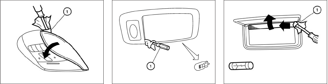
Use a cloth 䊊
1to protect the housing. Use a cloth 䊊
1to protect the housing. Use a cloth 䊊
1to protect the housing.
Map lights
LDI2094
Personal lights
WDI0670
Vanity mirror
LDI2096
8-28 Maintenance and do-it-yourself

Use a cloth 䊊
1to protect the housing.
䊊
1Remove the trim surrounding the housing.
䊊
2Remove the two screws holding the assem-
bly to the vehicle.
䊊
3Remove the assembly.
䊊
4Replace the necessary bulbs.
Cargo light
WDI0206
Rear combination light
LDI2085
Maintenance and do-it-yourself 8-29
If you have a flat tire, see “Flat tire” in the
“In case of emergency” section of this
manual.
TIRE PRESSURE
Tire Pressure Monitoring System
(TPMS)
This vehicle is equipped with the Tire
Pressure Monitoring System (TPMS). It
monitors tire pressure of all tires except
the spare. When the low tire pressure
warning light is lit and the “Tire Pressure
Low – Add Air” warning appears in the
vehicle information display, one or more of
your tires is significantly under-inflated. If
equipped, the system also displays pres-
sure of all tires (except the spare tire) on
the display screen by sending a signal
from a sensor that is installed in each
wheel.
The TPMS will activate only when the
vehicle is driven at speeds above 16 MPH
(25 km/h). Also, this system may not de-
tect a sudden drop in tire pressure (for
example a flat tire while driving).
For more details, refer to “Low tire pres-
sure warning light”in the “Instruments and
controls” section and “Flat tire” in the “In
case of emergency” section.
Tire inflation pressure
Check the tire pressures (including the
spare) often and always prior to long dis-
tance trips. The recommended tire pres-
sure specifications are shown on the
F.M.V.S.S./C.M.V.S.S. certification label
or the Tire and Loading Information label
under the “Cold Tire Pressure” heading.
The Tire and Loading Information label is
affixed to the driver side center pillar. Tire
pressures should be checked regularly
because:
●Most tires naturally lose air over time.
●Tires can lose air suddenly when
driven over potholes or other objects
or if the vehicle strikes a curb while
parking.
The tire pressures should be checked
when the tires are cold. The tires are
considered COLD after the vehicle has
been parked for 3 or more hours, or driven
less than 1 mile (1.6 km) at moderate
speeds.
The TPMS with Tire Inflation Indicator
provides visual and audible signals out-
side the vehicle for inflating the tires to the
recommended COLD tire pressure. For
more information, see “TPMS with Tire
Inflation Indicator” in the “Starting and
driving” section.
Incorrect tire pressure, including un-
der inflation, may adversely affect
tire life and vehicle handling.
WHEELS AND TIRES
8-30 Maintenance and do-it-yourself
the type of personally identifying data routinely
acquired during a crash investigation.
To read data recorded by an EDR, special equip-
ment is required and access to the vehicle or the
EDR is needed. In addition to the vehicle manu-
facturer and INFINITI retailer, other parties, such
as law enforcement, that have the special equip-
ment, can read the information if they have ac-
cess to the vehicle or the EDR. EDR data will only
be accessed with the consent of the vehicle
owner or lessee or as otherwise required or per-
mitted by law.
Genuine INFINITI Service Manuals for this model
year and prior can be purchased. A genuine
INFINITI Service Manual is the best source of
service and repair information for your vehicle.
This manual is the same one used by the factory-
trained technicians working at INFINITI retailer-
ships. Genuine INFINITI Owner’s Manuals can
also be purchased.
For USA
For current pricing and availability of genuine
INFINITI Service Manuals, contact:
1-800-450-9491
www.infiniti-techinfo.com
For current pricing and availability of genuine
INFINITI Owner’s Manuals, contact:
1-800-247-5321
For Canada
To purchase a copy of a genuine INFINITI Service
Manual or Owner’s Manual, for this model year
and prior, please contact your nearest INFINITI
retailer. For the phone number and location of an
INFINITI retailer in your area call the INFINITI
Satisfaction Center at 1-800-361-4792 and a
bilingual INFINITI representative will assist you.
OWNER’S MANUAL/SERVICE
MANUAL ORDER INFORMATION
9-32 Technical and consumer information
Product specificaties
| Merk: | Infiniti |
| Categorie: | Personenwagen |
| Model: | QX60 - 2014 |
Heb je hulp nodig?
Als je hulp nodig hebt met Infiniti QX60 - 2014 stel dan hieronder een vraag en andere gebruikers zullen je antwoorden
Handleiding Personenwagen Infiniti

22 September 2022
23 September 2022
22 September 2022
22 September 2022
22 September 2022
22 September 2022
22 September 2022
22 September 2022
23 September 2022
22 September 2022
Handleiding Personenwagen
- Personenwagen Ford
- Personenwagen Fiat
- Personenwagen Opel
- Personenwagen Renault
- Personenwagen Volvo
- Personenwagen Alfa Romeo
- Personenwagen Audi
- Personenwagen Hella
- Personenwagen Hyundai
- Personenwagen Kia
- Personenwagen Lancia
- Personenwagen Land Rover
- Personenwagen Lexus
- Personenwagen Maserati
- Personenwagen Mazda
- Personenwagen Mercedes
- Personenwagen Mini
- Personenwagen Nissan
- Personenwagen Peugeot
- Personenwagen Porsche
- Personenwagen Skoda
- Personenwagen Smart
- Personenwagen Subaru
- Personenwagen Suzuki
- Personenwagen Tesla
- Personenwagen Toyota
- Personenwagen Vauxhall
- Personenwagen Volkswagen
Nieuwste handleidingen voor Personenwagen

22 Oktober 2023

16 Oktober 2023
16 Oktober 2023
16 Oktober 2023
16 Oktober 2023

5 Oktober 2023
5 Oktober 2023
5 Oktober 2023
5 Oktober 2023
5 Oktober 2023