Humminbird 998C SI Handleiding
Humminbird
Navigator
998C SI
Lees hieronder de 📖 handleiding in het Nederlandse voor Humminbird 998C SI (160 pagina's) in de categorie Navigator. Deze handleiding was nuttig voor 65 personen en werd door 2 gebruikers gemiddeld met 4.5 sterren beoordeeld
Pagina 1/160


i
Thank You!
Thank you for choosing Humminbird®, America's #1 name in fishfinders.
Humminbird® has built its reputation by designing and manufacturing
top-quality, thoroughly reliable marine equipment. Your Humminbird® is
designed for trouble-free use in even the harshest marine environment. In
the unlikely event that your Humminbird® does require repairs, we offer an
exclusive Service Policy - free of charge during the first year after purchase,
and available at a reasonable rate after the one-year period. For complete
details, see the Warranty section in this manual. We encourage you to read
this installation and operations manual carefully in order to get full benefit
from all the features and applications of your Humminbird® product.
Contact our Customer Resource Center at either or visit our1-800-633-1468
web site at .humminbird.com
WARNING! This electronic chart is an aid to navigation designed to facilitate the use of
authorized government charts, not to replace them. Only official government charts and
notices to mariners contain all of the current information needed for the safety of
navigation, and the captain is responsible for their prudent use.
WARNING! This device should not be used as a navigational aid to prevent collision,
grounding, boat damage, or personal injury. When the boat is moving, water depth may
change too quickly to allow time for you to react. Always operate the boat at very slow
speeds if you suspect shallow water or submerged objects.
WARNING! Disassembly and repair of this electronic unit should only be performed by
authorized service personnel. Any modification of the serial number or attempt to repair
the original equipment or accessories by unauthorized individuals will void the warranty.
WARNING! This product contains chemicals known to the State of California to cause
cancer and/or reproductive harm.
WARNING! Do not travel at high speed with the unit cover installed. Remove the unit
cover before traveling at speeds above 20 mph.
NOTE: Some features discussed in this manual require a separate purchase, and some
features are only available on international models. Every effort has been made to clearly
identify those features. Please read the manual carefully in order to understand the full
capabilities of your model.
XM WX® is a registered trademark of XM Satellite Radio and Weather to the Power of X® is a
registered trademark of XM Satellite Radio Inc. All rights reserved.
ProMap™ and LakeMaster® are trademarked by or registered trademarks of Waypoint
Technologies, Inc.
Navionics® Gold, HotMaps™, and HotMaps™ Premium, Navionics® Classic Charts, and Platinum™
Cartography are trademarked by or registered trademarks of Navionics®.
800 Series™, 900 Series™, Cannon®, CannonLink™, Contour XD™, Down Imaging™, DualBeam
PLUS™, Fish ID+™, HumminbirdPC™, Humminbird®, InterLink™, One-Touch® Zoom,
QuadraBeam PLUS™, RTS™ Window, Side Imaging®, SmartCast®, SwitchFire™, Structure ID®,
Total Screen Update™, UniMap™, WeatherSense®, WhiteLine™, and X-Press™ Menu are
trademarked by or registered trademarks of Humminbird®.
© 2010 Humminbird®, Eufaula AL, USA. All rights reserved.
ATTENTION INTERNATIONAL CUSTOMERS: Products sold in the U.S. are not
intended for use in the international market. Humminbird® international units
provide international features and are designed to meet country and regional
regulations. Languages, maps, time zones, units of measurement, and warranty
are examples of features that are customized for Humminbird® international
units purchased through our authorized international distributors.
To obtain a list of authorized international distributors, please visit our web
site at www.humminbird.com or contact our Customer Resource Center at
(334) 687-6613.

Table of Contents
ii
Introduction 1
How Sonar Works ....................................................................................................................1
High Definition Side Imaging® Sonar (898c SI and 998c SI only)............................................2
DualBeam PLUS™ Sonar (858c, 898c SI, 958c, 998c SI)..........................................................3
QuadraBeam PLUS™ Sonar (optional-purchase QuadraBeam PLUS™ transducer only) ..........3
Universal Sonar 2......................................................................................................................4
How GPS and Cartography Work ............................................................................................4
Fishing System Configuration..................................................................................................5
Accessory Bus ..........................................................................................................................5
Video-Out and RS 232 Connectors ..........................................................................................6
Installation Overview 6
Control Head Installation 6
Gimbal Mounting the Control Head........................................................................................7
Connecting the Control Head Power Cable to the Boat......................................................11
Transducer Installation Overview 12
858c & 958c Transom Mount Transducer Installation
DualBeam PLUS™ Transducer, XNT 9 20 T (858c and 958c only) 13
Overview..................................................................................................................................13
Locating the transducer mounting location..........................................................................14
Preparing the Mounting Location ........................................................................................15
Assembling the Transducer and Initial Mounting................................................................16
Routing the Cable ..................................................................................................................20
Test and Finish the Installation..............................................................................................21
Locking Down the Transducer (Optional)..............................................................................23
858c & 958c Inside the Hull Transducer Installation
DualBeam PLUS™ Transducer, XNT 9 20 T (858c and 958c only) 24
Locating the transducer mounting location ........................................................................24
Trial installation ......................................................................................................................25
Routing the cable....................................................................................................................26
Permanently mounting the transducer ................................................................................26
898c SI & 998c SI Transom Mount Transducer Installation
Side Imaging Transducer, XHS 9 HDSI 180T (898c SI or 998c SI only) 27
Overview..................................................................................................................................28
Locating transducer mounting location................................................................................28
Mounting the transducer bracket to the boat......................................................................29
Attaching the pivot to the transducer ..................................................................................30
Mounting the transducer pivot assembly to the bracket....................................................30
Adjusting the running position of the transducer................................................................31
Routing the cable....................................................................................................................32
Testing the installation ..........................................................................................................33
Trolling Motor Transducer Installation 33
Trolling Motor Transducer Options ........................................................................................33
Test and Finish the Transducer Installation ..........................................................................33
GPS Receiver Installation Overview 34
Stem Mounting with an Existing 1" - 14 Thread Stem........................................................35
Access Under Mounting Location ........................................................................................36
No Access Under Mounting Location ..................................................................................36
Finish Routing the Cable and Check GPS Receiver Operation............................................37
531743-1_B

Table of Contents
iii
Testing the System Installation 38
Power On the Control Head 39
What’s on the Control Head 39
Key Functions 40
POWER/LIGHT Key..................................................................................................................40
VIEW Key ................................................................................................................................40
MENU Key ..............................................................................................................................40
4-WAY Cursor Control Key (RIGHT, LEFT, UP, or DOWN Cursor Keys) ................................41
VIEW PRESET Keys ................................................................................................................41
EXIT Key ..................................................................................................................................41
INFO Key ................................................................................................................................42
MARK Key................................................................................................................................42
GOTO Key ................................................................................................................................42
ZOOM (+/-) Keys ....................................................................................................................42
Multi-Media Card (MMC)/SD Slots 43
Add Maps to Your Fishing System ........................................................................................43
Update Software ....................................................................................................................44
Export Navigation Data ..........................................................................................................44
What’s on the Sonar Display 45
Understanding the Sonar Display..........................................................................................46
Real Time Sonar (RTS™) Window ........................................................................................46
SwitchFire™ ............................................................................................................................46
Freeze Frame and Active Cursor ............................................................................................47
Instant Image Update ............................................................................................................47
Sonar Bottom Presentation....................................................................................................47
What’s on the Side Imaging® Display (898c SI and 998c SI only) 48
Understanding the Side Imaging® Display ..........................................................................49
Side Imaging® Frequencies and Coverage............................................................................50
For Best Performance ............................................................................................................51
On the Water Interpretation ..................................................................................................51
Views 53
Side Imaging® View
(898c SI and 998c SI only)
....................................................................55
Down Imaging™ View
(898c SI and 998c SI only)
................................................................56
Sonar View ..............................................................................................................................57
Sonar Zoom View....................................................................................................................58
Split Sonar View......................................................................................................................59
Snapshot and Recording View
(optional-purchase MMC/SD card required)
........................60
Side Beam View
(optional-purchase QuadraBeam PLUS™ transducer required)
..................65
Bird’s Eye View........................................................................................................................67
Chart View ..............................................................................................................................68
Combo Views ..........................................................................................................................69
Combo Views: Functions ........................................................................................................69
Side Imaging/Sonar Combo View
(898c SI and 998c SI only)
..............................................69
Chart/Bird’s Eye Combo View................................................................................................70
Chart/Chart Combo View ......................................................................................................70
Chart/Sonar Combo View ......................................................................................................71
Chart/Side Imaging Combo View
(898c SI and 998c SI only)
..............................................71
Down Imaging™/Side Imaging® Combo View
(898c SI and 998c SI only)
..........................72

Table of Contents
iv
Chart/Down Imaging™ Combo View
(898c SI and 998c SI only)
........................................72
Down Imaging™/Sonar Combo View
(898c SI and 998c SI only)
........................................73
Down Imaging™/Side Imaging/Sonar Combo View
(898c SI and 998c SI only)
................73
View Orientation ....................................................................................................................74
Viewing Cartography 74
Introduction to Navigation 76
Waypoints, Routes, and Tracks..............................................................................................76
Save, Edit, or Delete a Waypoint ..........................................................................................77
Navigate to a Waypoint or Position ......................................................................................78
Add a Waypoint Target or Trolling Grid ................................................................................78
Save, Edit or Delete a Route..................................................................................................79
Save or Clear a Current Track ................................................................................................80
Edit, Delete, or Hide Saved Tracks ........................................................................................80
Man Overboard (MOB) Navigation........................................................................................81
The Menu System 82
Start-Up Options Menu 82
Simulator ................................................................................................................................83
System Status ........................................................................................................................83
Self Test ..................................................................................................................................83
Accessory Test ........................................................................................................................84
GPS Diagnostic View ..............................................................................................................84
X-Press™ Menu 85
Main Menu 85
Quick Tips for the Main Menu ..............................................................................................86
Note for all Menu Settings ....................................................................................................86
User Mode (Normal or Advanced) ........................................................................................87
Sonar X-Press™ Menu 88
Active Side
(Combo Views only)
..............................................................................................88
Split Position
(Combo Views only)
..........................................................................................88
Sensitivity ................................................................................................................................89
Upper Range
(Advanced: Sonar, Split Sonar and Active Sonar Side Views only)
..................89
Lower Range ..........................................................................................................................90
Chart Speed ............................................................................................................................90
Quad Layout
(with optional-purchase QuadraBeam PLUS™ Transducer, Side Beam View only)
............90
Bottom Lock
(Sonar Zoom View only)
....................................................................................91
Bottom Range
(Sonar Zoom View only, when Bottom Lock is On)
........................................91
Cancel Navigation
(only when Navigating)
............................................................................91
Side Imaging® X-Press™ Menu
(Side Imaging Views only [898c SI, 998c SI])
92
Active Side
(Combo Views only)
..............................................................................................92
Split Position
(Combo Views only)
..........................................................................................92
SI Side......................................................................................................................................93
SI Sensitivity............................................................................................................................93
SI Enhance ..............................................................................................................................93
SI Range ..................................................................................................................................94
Chart Speed ............................................................................................................................94
SI Colors ..................................................................................................................................94

Table of Contents
v
Down Imaging X-Press™ Menu™
(Down Imaging™ Views only [898c SI, 998c SI])
95
Active Side
(Combo Views only)
..............................................................................................95
Split Position
(Combo Views only)
..........................................................................................95
Down Sensitivity ....................................................................................................................96
Upper Range
(Advanced: Down Imaging™ Views only)
........................................................96
Lower Range ..........................................................................................................................97
Chart Speed ............................................................................................................................97
SI Colors ..................................................................................................................................97
Cancel Navigation
(only when Navigating)
............................................................................97
Navigation X-Press™ Menu 98
Active Side
(Combo Views only)
..............................................................................................98
Split Position
(Combo Views only)
..........................................................................................98
Waypoint [Name]
(Only with an active cursor on a waypoint)
..............................................99
Cursor to Waypoint
(Chart or Combo View only)
....................................................................99
Save Current Track..................................................................................................................99
Clear Current Track ................................................................................................................99
Save Current Route
(only when Navigating)
........................................................................100
Skip Next Waypoint
(only when Navigating)
........................................................................100
Cancel Navigation
(only when Navigating)
..........................................................................100
Cancel MOB Navigation
(only when MOB Navigation is activated)
....................................100
Remove Target
(only if a Target is Active)
............................................................................100
Remove Grid
(only if a Grid is Active)
....................................................................................100
Waypoint [Name]
(Most recently-created waypoint)
............................................................101
Snapshot and Recording X-Press™ Menu
(Snapshot and Recording View only)
102
Start Recording
(optional-purchase MMC/SD Card, Snapshot and Recording View only)............................102
Stop Recording (optional-purchase MMC/SD Card only) ......................................................102
Delete Image (optional-purchase MMC/SD Card, Snapshot and Recording View only) ........102
Delete All Images
(optional-purchase MMC/SD Card, Snapshot and Recording View only)............................103
Delete Recording
(optional-purchase MMC/SD Card, Snapshot and Recording View only)............................103
Delete All Recordings
(optional-purchase MMC/SD Card, Snapshot and Recording View only)............................103
Pings Per Second
(optional-purchase MMC/SD Card, Snapshot and Recording View only)............................103
Playback Speed
(optional-purchase MMC/SD Card, Snapshot and Recording View only)............................103
Stop Playback (optional-purchase MMC/SD Card only) ........................................................104
Alarms Menu Tab 105
Depth Alarm..........................................................................................................................105
Fish ID Alarm ........................................................................................................................105
Low Battery Alarm................................................................................................................106
Aux. Temp Alarm
(with optional-purchase temp. probe or Temp/Speed only)
....................106
Temp. Alarm ..........................................................................................................................106
Off Course Alarm ..................................................................................................................106
Arrival Alarm..........................................................................................................................107
Drift Alarm ............................................................................................................................107
Alarm Tone ............................................................................................................................107

Table of Contents
vi
Sonar Menu Tab 108
Beam Select ..........................................................................................................................108
Side View Frequency
(Side Imaging® and Down Imaging™ Views only [898c SI, 998c SI]) ................................
109
Surface Clutter......................................................................................................................109
SwitchFire™ ..........................................................................................................................109
Fish ID+™..............................................................................................................................110
Fish ID Sensitivity..................................................................................................................110
Real Time Sonar (RTS™) Window ......................................................................................111
Sonar Colors..........................................................................................................................111
Bottom View..........................................................................................................................111
Zoom Width
(Sonar Zoom View only)
..................................................................................112
83 kHz Sensitivity
(Advanced)
..............................................................................................112
455 kHz Sensitivity
(Advanced, with optional purchase QuadraBeam PLUS™ transducer) ..................................
112
Depth Lines
(Advanced)
........................................................................................................113
Noise Filter
(Advanced)
........................................................................................................113
Max Depth
(Advanced)
..........................................................................................................114
Water Type
(Advanced)
........................................................................................................114
Transducer Select..................................................................................................................114
Color Bar................................................................................................................................115
Temperature Graph
(Sonar View only, with Temperature input)
..........................................115
Down Imaging™ Beam Width
(Advanced)
..........................................................................115
Navigation Menu Tab 116
Current Track ........................................................................................................................116
Saved Tracks..........................................................................................................................117
Waypoints..............................................................................................................................117
Routes....................................................................................................................................118
Chart Orientation..................................................................................................................118
North Reference....................................................................................................................118
Waypoint Decluttering
(Advanced)
......................................................................................118
Trolling Grid Rotation............................................................................................................119
Trackpoint Interval ................................................................................................................119
Track Min Distance
(Advanced)
............................................................................................119
Track Color Range ................................................................................................................119
Map Datum
(Advanced)
........................................................................................................120
Course Projection Line..........................................................................................................120
3D View Outline ....................................................................................................................120
Export All Nav Data
(Advanced)
..........................................................................................120
Delete All Nav Data
(Advanced)
..........................................................................................120
Continuous Navigation Mode..............................................................................................120
GPS Receiver Override
(Advanced)
......................................................................................120
Chart Menu Tab 121
Lat/Lon Grid ..........................................................................................................................121
Navaids on Bird’s Eye View..................................................................................................121
Chart Select ..........................................................................................................................121
Set Simulation Position
(Advanced)
....................................................................................122
Set Map Offset
(Advanced)
..................................................................................................122
Clear Map Offset
(Advanced)
................................................................................................122
Shaded Depth ......................................................................................................................122
Chart Detail Level
(optional-purchase Navionics® charts only)
............................................123

Table of Contents
vii
Map Borders..........................................................................................................................123
Spot Soundings
(optional-purchase Navionics® charts only)
................................................123
NVB Chart Preference ........................................................................................................124
Contour Lines
(optional-purchase LakeMaster® charts only)
................................................124
Depth Colors
(optional-purchase LakeMaster® charts only)
..................................................124
Depth Highlight
(optional-purchase LakeMaster® charts only)
............................................124
Depth Highlight Range (+/-)
(optional-purchase LakeMaster® charts only) ........................
124
Water Level Offset
(optional-purchase LakeMaster® charts only)
........................................124
Shallow Water Highlight
(optional-purchase LakeMaster® charts only)
..............................125
Lake List
(optional-purchase LakeMaster® charts only)
........................................................125
Setup Menu Tab 126
Units - Depth ........................................................................................................................126
Units - Temp
(International only)
..........................................................................................126
Units - Distance
(with Speed input only)
..............................................................................126
Units - Speed
(with Speed input only)
..................................................................................127
User Mode ............................................................................................................................127
Language
(International only)
................................................................................................127
Triplog Reset
(with Speed input only)
..................................................................................127
Restore Defaults....................................................................................................................127
Select Readouts
(Advanced)
................................................................................................128
Depth Offset
(Advanced)
......................................................................................................129
Aux. Temp Offset
(Advanced)
................................................................................................129
Temp. Offset
(Advanced)
......................................................................................................129
Speed Calibration
(Advanced, with Speed paddlewheel only)
............................................129
Local Time Zone
(Advanced)
................................................................................................129
Daylight Saving Time
(Advanced)
........................................................................................129
Position Format
(Advanced)
..................................................................................................130
Time Format
(Advanced, International only)
..........................................................................130
Date Format
(Advanced, International only)
..........................................................................130
Digits Format
(Advanced)
......................................................................................................130
NMEA Output
(Advanced)
....................................................................................................130
Sonar......................................................................................................................................131
Demonstration ......................................................................................................................131
Sound Control ......................................................................................................................131
Video Out ..............................................................................................................................131
Views Menu Tab 132
Accessories Menu Tab 132
Screen Snapshot
(optional-purchase MMC/SD Cards only)
................................................133
AIS
(optional-purchase AIS equipment only)
........................................................................133
Troubleshooting 136
Fishing System Doesn’t Power Up ......................................................................................136
Fishing System Defaults to Simulator with a Transducer Attached ................................136
Display Problems 137
Finding the Cause of Noise 138


Introduction
1
Introduction
Your Humminbird® Fishing System is configured as follows:
• Wide Screen Fishing System withHumminbird® 858c Combo:
DualBeam PLUS™ Sonar and Chartplotting. GPS Receiver included.
• Wide Screen Fishing System withHumminbird® 898c SI Combo:
Side Imaging® Sonar, DualBeam PLUS™ Sonar, and Chartplotting.
GPS Receiver included.
• Ultra Wide Screen Fishing System withHumminbird® 958c Combo:
DualBeam PLUS™ Sonar and Chartplotting. GPS Receiver included.
• Ultra Wide Screen Fishing SystemHumminbird® 998c SI Combo:
with Side Imaging® Sonar, DualBeam PLUS™ Sonar, and
Chartplotting. GPS Receiver included.
How Sonar Works
Sonar technology is based on sound waves. The Fishing System uses sonar
to locate and define structure, bottom contour and composition, as well as
depth directly below the transducer.
Your Fishing System sends a sound wave signal and determines distance by
measuring the time between the transmission of the sound wave and when
the sound wave is reflected off of an object; it then uses the reflected signal
to interpret location, size, and composition of an object.
Sonar is very fast. A sound wave can travel from the surface to a depth of
240 ft (70 m) and back again in less than 1/4 of a second. It is unlikely that
your boat can "outrun" this sonar signal.
SONAR is an acronym for SOund and
NAvigation Ranging. Sonar utilizes precision
sound pulses or "pings" which are emitted into
the water in a teardrop-shaped beam.
The sound pulses "echo" back from objects in
the water such as the bottom, fish and other
submerged objects. The returned echoes are
displayed on the LCD screen. Each time a new
echo is received, the old echoes are moved
across the LCD, creating a scrolling effect.
When all the echoes are viewed side by side,
an easy to interpret "graph" of the bottom, fish
and structure appears.

2
Introduction
The sound pulses are transmitted at various
frequencies depending on the application.
Very high frequencies (455 kHz) are used for
greatest definition, but the operating depth is
limited. High frequencies (200 kHz) are
commonly used on consumer sonar and
provide a good balance between depth
performance and resolution. Low frequencies
(83 kHz) are typically used to achieve greater
depth capability.
The power output is the amount of energy
generated by the sonar transmitter. It is
commonly measured using two methods:
• Root Mean Square (RMS) measures power
output over the entire transmit cycle.
• Peak to Peak measures power output at the
highest points.
The benefits of increased power output are
the ability to detect smaller targets at greater
distances, ability to overcome noise, better
high speed performance and enhanced depth
capability.
High Definition
Side Imaging®Sonar
(898c SI and 998c SI only)
The 898c SI Combo and 998c SI Combo
use Side Imaging® sonar to provide a
wide yet precise survey of a large area
of water, including detailed bottom
topography and fish-attracting structure
orientation. The Side Imaging®
transducer returns are processed into an
image similar to an aerial photograph.
Typically, the Side Imaging® sonar can
search an area that is 480 feet wide (240
to each side), with a typical depth
performance of 150 feet when the Side
Imaging® Sonar frequency is set for
455kHz. The side beams can be
operated at one of two frequencies:
455 kHz or 800 kHz. Selecting 800 kHz
produces the sharpest image, but the
search area to each side and the depth
capability are limited as compared to the
455 kHz frequency. See What’s on the
Side Imaging® Display and
Understanding Side Imaging® for more
information.
60°
83kHz
20°
200kHz
86°
455kHz
86°
455kHz

Introduction
3
DualBeam PLUS™ Sonar
(858c, 898c SI, 958c, 998c SI)
The Fishing System uses a 200/83 kHz
DualBeam PLUS™ sonar system with a wide
(60°) area of coverage. DualBeam PLUS™
sonar has a narrowly focused 20° center
beam, surrounded by a second beam of 60°,
expanding your coverage to an area equal to
your depth. In 20 feet of water, the wider
beam covers an area 20 feet wide.
DualBeam PLUS™ sonar returns can be
blended together, viewed separately, or
compared side-by-side. DualBeam PLUS™ is
ideal for a wide range of conditions - from
shallow to very deep water in both fresh and
salt water. Depth capability is affected by
such factors as boat speed, wave action,
bottom hardness, water conditions, and
transducer installation.
QuadraBeam PLUS™ Sonar
(optional-purchase QuadraBeam PLUS™
transducer only)
Your Fishing System supports the
optional-purchase QuadraBeam PLUS™
transducer. QuadraBeam PLUS™ sonar
provides a wide (90°) area of coverage.
QuadraBeam PLUS™ starts with two
fan-shaped 35° 455 kHz Side Structure
locating sonar beams to spot fish, bait,
and structure to the left and right of the
boat over an area of the bottom that’s
always equal to twice your depth.
For a detailed view below the boat,
QuadraBeam PLUS™ uses DualBeam
PLUS™ technology, with precision 20°
and wide 60° beams. QuadraBeam
PLUS™ finds more fish faster, and can
even tell you where to put your bait by
showing if fish are to the left, right, or
directly beneath your boat.
90° Total Coverage
Bottom Coverage
=
2 x Depth
35° 60° 20° 35°
455 kHz 455 kHz
83 kHz
200 kHz

Introduction 4
Universal Sonar 2
Your Fishing System supports Universal Sonar 2, a state-of-the-art,
integrated and protected transducer that is built into the lower unit of
Minnkota trolling motors. With Universal Sonar 2, all wiring is concealed
inside the indestructible composite shaft—out of sight and out of harm’s
way, with no clamps, ties, or exposed wires. Universal Sonar 2 features new
temperature sensing and the performance of DualBeam PLUS™ technology.
An expanded view and greater bottom detail gives you a totally new
perspective of the water below, along with optimal sonar performance to
help you find fish.
How GPS and Cartography Work
Your Fishing System also supports GPS (Global Positioning System) and
chartplotting. It uses GPS and sonar to determine your position, display it on
a grid, and provide detailed underwater information.
GPS uses a constellation of satellites that
continually send radio signals to the earth. The
GPS receiver on your boat receives signals from
satellites that are visible to it. Based on time
differences between each received signal, the
GPS receiver determines its distance to each
satellite. With distances known, the GPS
receiver mathematically triangulates its own
position. With once per second updates, the
GPS receiver then calculates its velocity and
bearing.
GPS was originally intended for military use; however, civilians may also take
advantage of its highly accurate position capabilities, typically within +/- 4
meters, depending on conditions. This means that 95% of the time, the GP
receiver will read a location within 4.5 meters of your actual position. Yo
GPS Receiver also uses information from WAAS (the Wide Are
Augmentation System), EGNOS (the European Geostationary Navigat
Overlay Service), and MSAS (the MTSAT Satellite Augmentation Syst
satellites if they are available in your area.
The following GPS functionality is currently supported by the Fishing Syst
when it is connected to the included GPS receiver:
• View current position
• View current track (breadcrumb trail)
• View precision speed and heading from your GPS receiver
• Save tracks, waypoints, and routes
• Travel a route and navigate from one waypoint to the next.
See Chart View Multi-Media Card (MMC)/SD Slotsand Introduction to
Add Maps to Your Fishing System for more information.

Installation Introduction
5
Fishing System Configuration
The Fishing System has a wide variety of configurations that will influence t
installation. The accessory bus, video output, and RS 232 connectors allow yo
to expand your Fishing System capabilities. As you expand the configuratio
the menu options that correspond with the connected accessory will be added
to the menu system.
Please read all instructions that are relevant for your configuration befor
beginning the installation process.
Accessory Bus
Use the Accessory Bus to expand the
functionality of your Fishing System.
Accessories plug directly into the Fishing
System and enable advanced features such as
WeatherSense®, SmartCast®, and the AS WX 1
Satellite Weather Receiver.
When an accessory is plugged into the Fishing
System, additional functions will be added
to the menu system automatically. See
Accessories Menu Tab Fishing Systemand
Accessories in this manual. Also, see the
accessory’s operations manual for additional
details.
NOTE: Accessories to enable WeatherSense®, SmartCast®, and the AS WX
Satellite Weather Receiver require separate purchases. Visit our web site at
humminbird.com 1-800-633-1468or contact our Customer Resource Center at
for details.
Accessory Bus
The Fishing System has a wide variety of configurations
Video Out
1
RS 232 Connector
2
Power
3
Optional “Y” Cable
GPS Receiver
SmartCast® Wireless Sonar Link
6
7
8
Temperature
4
WeatherSense®
9
5
1
2
3
4
5
6
7
8
9
Sonar Transducer with Temperature
10
10
Speed
5

Installation - Gimbal Mount
7
Gimbal Mounting the Control Head
If you are gimbal mounting the Humminbird®, you can pre-assemble the unit
in order to plan the best mounting location.
In addition to the hardware supplied with your control head, you will need a
powered hand drill and various drill bits, various hand tools, including a Phillips
head screwdriver, a socket wrench and a flat head screwdriver, a marker or
pencil, safety glasses and dust mask, and marine-grade silicone sealant.
1. Place the control head into the gimbal bracket. Make sure that the
straight side of the gimbal arm is against the back side of the control
head.
2. Place a 1" (25 mm) diameter black washer on the gimbal knob and
then thread the knob and washer into the housing. Tighten the
gimbal knob to secure the control head to the mount. Repeat step 2
for the other side.
You can now place the control head in various locations to decide which i
best for mounting. Rotating the mounting bracket to the top of the contro
head will allow for overhead mounting. The chosen mounting area shoul
allow for sufficient room so the control head can pivot through the full ti
range and allow for easy removal and installation.
NOTE: You can drill the cable pass hole underneath the gimbal bracket, allowing
you to thread the cables through the knock-out holes in the mount; however, if
you cannot drill the hole directly under the mounting bracket, then you will need
to drill the cable pass hole behind the bracket, and will need to mount the hole
cover there instead.
NOTE: When drilling holes in fiberglass hulls, it is best to start with a smaller bi
and use progressively larger drill bits to reduce the chance of chipping or flaking
the outer coating. Fill all holes with marine grade silicone sealant.
NOTE: You must have underside access to the mounting location to pass the
cables through to the surface. Also, make sure that the mounting surface is
adequately supported to protect the control head from excessive wave shock and
vibration and provide visibility while in operation.
3. After the mounting location has been determined, loosen the gimbal
knobs and remove the control head from the gimbal bracket.
Washer
1
Gimbal Knob
2
Gimbal Bracket
3
1
2
3

Installation - Gimbal Mount
9
Remove the hole cover, drill the two mounting holes using a 9/64"
bit. Do not install the hole cover at this time.
6b. If the cables cannot be routed directly beneath the mounting
bracket, mark and drill a 1" (25 mm) hole that will allow you to run
the cables close to the bracket. Pass the cables through the 1" (25
mm) hole, routing the cables through the grommet and pressing the
grommet into place. Place the hole cover over the mounting surface
hole, then use it to mark the position of the two mounting screws.
Remove the hole cover, drill the two mounting holes using a 9/64"
(3.5 mm) bit, fill them with marine-grade silicone, then replace the
hole cover and insert the #8 Phillips countersink wood screws.
Hand-tighten only.
7. Place the mounting bracket on the mounting surface aligned with
the drilled holes and fill the mounting holes with marine grade
silicone. Insert the four #10 Slotted-Hex wood screws into the
mounting holes. .Hand-tighten only
8. If the cable pass through-hole is beneath the mounting bracket, you
will need to install the hole cover. Place the hole cover over the
mounting bracket cable pass through-hole and align with holes
drilled in step 6a. Insert the #8 Phillips countersink wood screws.
Hand tighten only.
NOTE: Be sure that the cables pass through the slots on the hole cover and that
there is enough cable slack to allow for the control head to pivot through its full tilt
range. Extra cable slack will also help when connecting/disconnecting the cables.
1
Cables Routed Directly Beneath Mounting Bracket
Gimbal Bracket
1
Hole Cover
2
2
Installation - Gimbal Mount 10
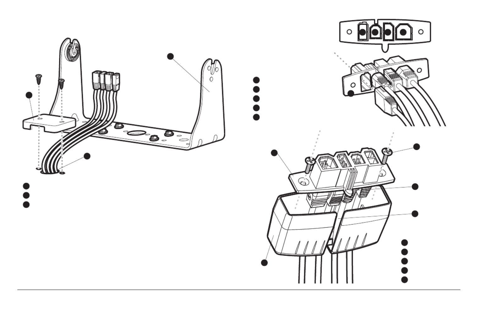
9. Insert cable connectors into the proper recesses on the cable
collector insert. The cable connectors are keyed to prevent reverse
installation, so be careful not to force the connectors into the wrong
slots. If you don’t have a cable for every hole in the insert, install the
blank plugs to protect the control head from the weather.
1
2
Cables Routed Behind Mounting Bracket
3
Gimbal Bracket
1
Grommet
2
Hole Cover
3
Cable Collector Insert
1
Screws
2
Cable Collector Cover
3
Tab on Insert
4
Slot on Cover
5
1
2
3
4
5
Power
1
Temp/Speed
2
Communications/GPS
3
Transducer
4
Cable Collector Insert
5
1 2 3 4
5

12
Installation - Power
NOTE: In order to minimize the potential for interference with other marine
electronics, a separate power source (such as a second battery) may be
necessary.
You are now ready to install the transducer. Find the section that refers to
your specific transducer installation method.
Transducer Installation Overview
Proceed to the installation section that matches your transducer type. You
choices are as follows:
• DualBeam PLUS™ (XNT 9 20 T), Transom Mount858c, 958c:
• DualBeam PLUS™ (XNT 9 20 T), Inside the Hull Mount858c, 958c:
• Side Imaging® (XHS 9 HDSI 180T), Transom Moun898c SI, 998c SI:
• Trolling Motor Transducer InstallationAll units:
NOTE: Due to the wide variety of hulls, only general instructions are presented
in this installation guide. Each boat hull represents a unique set of requirements
that should be evaluated prior to installation. It is important to read the
instructions completely and understand the mounting guidelines before
beginning installation.
1a. If a fuse terminal is available, use crimp-on type electrical
connectors (not included) that match the terminal on the fuse
panel. Attach the black wire to ground (-), and the red wire to
positive (+) 12 VDC power. Install a 3 amp fuse (not included) for
protection of the unit. Humminbird® is not responsible for over-
voltage of over-current failures.
or...
1b. If you need to wire the control head directly to a battery, obtain
and install an inline fuse holder and a 3 amp fuse (not included)
for the protection of the unit. Humminbird® is not responsible for
overvoltage or over-current failures.
NOTE:
If the included transducer will not work for your application, you may
exchange it, NEW and UNASSEMBLED, with mounting hardware included, fo
a transducer appropriate for your application - often at very little or no charge
depending on the transducer. Call the Humminbird® Customer Resource
Center at for details and pricing, or visit1-800-633-1468 humminbird.com.

13 Transom Mount - DualBeam PLUS™
858c & 958c Transom Mount Transducer Installation
DualBeam PLUS™ Transducer, XNT 9 20 T (858c and 958c only)
The DualBeam PLUS™ transducer uses a Two Piece Kick-up transducer
mounting bracket.
NOTE: Due to the wide variety of hulls, only general instructions are presented in
this installation guide. Each boat hull represents a unique set of requirements that
should be evaluated prior to installation. It is important to read the instructions
completely and understand the mounting guidelines before beginning
installation.
NOTE: Your transducer may not look exactly like the transducer shown in the
illustrations, but it will mount in exactly the same way.
Overview
If you will be installing a DualBeam PLUS™ transom mounted transducer, u
the procedures in this section. There are several procedures you will have to
perform in order to install a transom-mounted transducer. They are as
follows:
• Locate the transducer mounting location
• Prepare the mounting location
• Assemble the transducer and perform initial mounting
• Route the transducer cable
• Connect the transducer cable
• Perform a final test of the transom transducer installation.
In addition to the hardware supplied with your transducer, you will need a
powered hand drill and various drill bits, various hand tools, including a rul
or straightedge, a level, a 12" plumb line (weighted string or monofilamen
line), marker or pencil, safety glasses and dust mask, and marine-grade
silicone sealant.
NOTE: When drilling holes in fiberglass hulls, it is best to start with a smaller bi
and use progressively larger drill bits to reduce the chance of chipping or flaking
the outer coating.

15 Transom Mount - DualBeam PLUS™
• If the transom is behind the propeller(s), it may be impossible to find
an area clear from turbulence, and a different mounting technique or
transducer type should be considered, such as an Inside the Hull
Transducer (see Inside the Hull Transducer Installation).
• If you plan to trailer your boat, do not mount the transducer too close
to trailer bunks or rollers to avoid moving or damaging the transducer
during loading and unloading of the boat.
• If high speed operation is critical, you may want to consider using an
In-Hull transducer instead of this Transom Mount transducer.
NOTE: The hydrodynamic shape of your transducer allows it to point straight down
without deadrise adjustment.
NOTE: If you cannot find a transom mount location that will work for your high-
speed application, find an In-Hull Transducer by contacting our Customer Resource
Center at either 1-800-633-1468 or by visiting our web site at humminbird.com.
2. Preparing the Mounting Location
In this procedure, you will determine the mounting location and drill two
mounting holes, using the transducer mounting bracket as a guide.
1. Make sure that the boat is level on the trailer, both from port to
starboard and from bow to stern, by placing your level on the deck of
the boat, first in one direction, then in the other.
2. Hold the mounting bracket against the transom of the boat in the
location you have selected. Align the bracket horizontally, using the
level; make sure that the lower corner of the bracket does not
protrude past the bottom of the hull, and there is at least 1/4"
clearance between the bottom of the bracket and the bottom of the
transom for fiberglass boats, and 1/8" clearance for aluminum
boats.
NOTE: If you have a flat-bottomed aluminum boat, some additional adjustment
may be needed to accommodate the rivets on the bottom of the boat (i.e. the gap
may need to be a little smaller than 1/8"). This will help you to avoid excessive
turbulence at high speeds.
NOTE: If your propeller moves clockwise (in forward, as you're facing the stern o
the boat from behind), mount the transducer on the starboard side, and align the
bottom right corner of the mounting bracket with the bottom of the boat. If your
propeller moves counter-clockwise (in forward, as you're facing the stern of the
boat from behind), mount the transducer on the port side, and align the bottom
left corner of the mounting bracket with the bottom of the boat.
Positioning the
Mounting Bracket
Level
Level
Boat Hull Types Require
Different Mounting Positions
1/4” for fiberglass
1/8” for aluminum

18
Transom Mount - DualBeam PLUS™
3. Put the pivot bolt through the assembly to hold it in position and
loosely install the nut, but do NOT tighten the nut at this time. Insert
the pivot arm assembly into the mounting bracket. Do NOT snap the
assembly closed, as you will need to access the mounting bracket in
the next step.
NOTE: If the pivot assembly is snapped closed over the mounting bracket, use a
flat head screwdriver or similar tool to gently pry the assembly away from the
mounting bracket.
4. Align the mounting bracket transducer assembly with the drilled
holes in the transom. With a 5/16" socket driver, mount the assembly
to the transom using the two #10 - 1" long screws provided.
NOTE: Make sure that the mounting
screws are snug, but do not fully
tighten the mounting screws at this
time to allow the transducer
assembly to slide for adjustment
purposes.
5. Snap the pivot arm down
into place.
6. Adjust the initial angle of the
transducer from back to front
by rotating the transducer
until the side seam on the
transducer is almost parallel
with the bottom of the boat,
one click at a time in either
direction.
Mounting the Assembly to the Transom
Inserting the Pivot Bolt Inserting the Pivot Arm Assembly into
the Mounting Bracket

24
858c & 958c Inside the Hull Transducer Installation
DualBeam PLUS™ Transducer, XNT 9 20 T (858c and 958c only)
NOTE: Do NOT install the Side Imaging transducer inside the hull, as the side®
looking beams cannot penetrate the hull. Only the DualBeam PLUS™ transducer
can be mounted inside the hull.
If you choose to mount your transducer of your boat, performinside the hull
the procedures in this section. In-hull mounting generally produces good
results in single thickness fiberglass-hulled boats. Humminbird® cannot
guarantee depth performance when transmitting and receiving through the
hull of the boat, since some signal loss occurs. The amount of loss depends
on hull construction and thickness, as well as the installation position and
process.
NOTE: In-hull mounting requires an installed and operational control head.
NOTE: The integral temperature probe will not work with in-hull mounting, so
you may either want to consider purchasing a Temperature/Speed accessory, a
Temp. Sensor, or obtaining a different transducer. Humminbird® offers a
transducer exchange program to swap the NEW and UNASSEMBLED transducer,
accompanied by mounting hardware, for one without an integral temperature
probe. Call the Humminbird® Customer Resource Center at 1-800-633-1468 for
details, or visit humminbird.com for more information.
NOTE: Your transducer may not look exactly like the transducer shown in the
illustrations, but it will mount in exactly the same way.
There are several procedures you will have to perform in order to install a
transducer inside the hull. They are as follows:
• Locate transducer mounting location
• Perform a trial installation
• Route the transducer cable
• Permanently mount the transducer
1. Locating the transducer mounting location
Decide where to install the transducer on the inside of the hull. Consider the
following to find the best location:
• Observe the outside of the boat hull to find the areas that are mostly
free from turbulent water. Avoid ribs, strakes and other protrusions,
as these create turbulence.
• As a general rule, the faster the boat can travel, the further aft and
closer to the centerline of the hull the transducer has to be located
in order to remain in contact with the water at high speeds.
This installation requires slow-cure two-part epoxy. Do not use silicone
or any other soft adhesive to install the transducer, as this material
reduces the sensitivity of the unit. Do not use five-minute epoxy, as it has
a tendency to cure before all the air bubbles can be purged, thus
reducing signal strength.
Inside the Hull Mount - DualBeam PLUS™
Product specificaties
| Merk: | Humminbird |
| Categorie: | Navigator |
| Model: | 998C SI |
Heb je hulp nodig?
Als je hulp nodig hebt met Humminbird 998C SI stel dan hieronder een vraag en andere gebruikers zullen je antwoorden
Handleiding Navigator Humminbird

10 Juni 2023
26 Mei 2023
19 Mei 2023
10 Mei 2023
1 Mei 2023
24 Januari 2023
15 Januari 2023
8 November 2022
Handleiding Navigator
- Navigator Philips
- Navigator Sony
- Navigator Asus
- Navigator Garmin
- Navigator Grundig
- Navigator JVC
- Navigator Kenwood
- Navigator Motorola
- Navigator Medion
- Navigator Nokia
- Navigator Pioneer
- Navigator Acer
- Navigator Airis
- Navigator Alfa Romeo
- Navigator Alpine
- Navigator Audi
- Navigator Audiovox
- Navigator Autovision
- Navigator Becker
- Navigator Binatone
- Navigator Blaupunkt
- Navigator BMW
- Navigator Boss
- Navigator Bushnell
- Navigator Danew
- Navigator Dual
- Navigator Dynavin
- Navigator Eagle
- Navigator Eclipse
- Navigator ESX
- Navigator Falk
- Navigator Furuno
- Navigator Goclever
- Navigator Harman Kardon
- Navigator Hitachi
- Navigator Honda
- Navigator Igo
- Navigator Insignia
- Navigator Kalkhoff
- Navigator Kapsys
- Navigator Kia
- Navigator Lanzar
- Navigator Lenco
- Navigator Lowrance
- Navigator Magellan
- Navigator Marquant
- Navigator Maxcom
- Navigator Mazda
- Navigator Midland
- Navigator Mio
- Navigator Nav N Go
- Navigator Navigon
- Navigator Navitel
- Navigator Navman
- Navigator Parrot
- Navigator Polaroid
- Navigator Pyle
- Navigator Raymarine
- Navigator Route 66
- Navigator Sanyo
- Navigator Seecode
- Navigator Silvercrest
- Navigator Simrad
- Navigator Skoda
- Navigator Soundstream
- Navigator Sygic
- Navigator Sylvania
- Navigator Teasi
- Navigator Thomson
- Navigator TomTom
- Navigator Toyota
- Navigator Uniden
- Navigator VDO
- Navigator VDO Dayton
- Navigator Viamichelin
- Navigator Volkswagen
- Navigator Xzent
- Navigator Zebra
- Navigator Zenec
- Navigator Jensen
- Navigator Overmax
- Navigator Caliber
- Navigator Chrysler
- Navigator Clarion
- Navigator Conrad
- Navigator Cobra
- Navigator Celestron
- Navigator Scosche
- Navigator IZZO Golf
- Navigator Rand McNally
- Navigator Lark
- Navigator Whistler
- Navigator CarTrek
- Navigator GlobalSat
- Navigator Wahoo Fitness
- Navigator Coyote
- Navigator Coyote Systems
- Navigator GolfBuddy
- Navigator ModeCom
- Navigator Pharos
- Navigator V7
- Navigator Cheetah
- Navigator Cydle
- Navigator LXNAV
- Navigator Planet Audio
- Navigator Voice Caddie
- Navigator SkyCaddie
- Navigator TELE System
- Navigator Zoleo
- Navigator Dashmate
Nieuwste handleidingen voor Navigator
12 Maart 2025
14 December 2024
14 December 2024
14 December 2024
14 December 2024
7 December 2024
7 December 2024
24 November 2024
16 November 2024
16 November 2024