Ganz DigiMaster DR-4FX1 Handleiding
Ganz
Bewakingscamera
DigiMaster DR-4FX1
Lees hieronder de 📖 handleiding in het Nederlandse voor Ganz DigiMaster DR-4FX1 (102 pagina's) in de categorie Bewakingscamera. Deze handleiding was nuttig voor 8 personen en werd door 2 gebruikers gemiddeld met 4.5 sterren beoordeeld
Pagina 1/102

(FW Version 15xx) 10

2
CONTENT
MONITORING ARCHIVING
3 Start up / Shutdown start the Archive menu 59 To
5 Live Screen At a Glan ce
SYSTEM SETTING WEB VIEWER
12 To move to the System Setup menu What is the Web Viewer? 62
13 64 Camera Setting Live
19 Display Setting Search 68
24 70 Audio Setup Setup
25 User Setting
27 Network Setup
30 System Setting
34 Storage
37 Event Setup
RECORD SETTING MOBILE VIEWER
46 To start the Record Setup menu GanzView 82
47 Record Setup
SEARCH ARCHIVE VIEWER
52 To move to the Search menu while Getting started with the Backup Play 94
in monitoring Backup Player At a Glance 95
52 To move to the Search menu while
in playback mode
PLAY APPENDIX
56 If you want to play 98 Specication

3
Monitoring
Start Up/ Shutdown
START
You can connect DVR to a PC in the same network and control or manipulate it on the PC monitor.
1. 12 Connect the adaptor to the V power input port in the rear panel of DVR. DC
Make connection when the power is not applied yet.
2. Connect AC cable to the power source. With a beep, the logo screen appears several
seconds after the front LED turns on.
3. When the booting process is completed, the live screen then the login screen appears.
Log In
To manipulate or access the menus of DVR, you should have logged in.
1. When the system starts, the login screen appears.
2. Select a user and provide the password.
The default password of the "ADMIN" account is
"1234".
3. Click . <OK>
If the login information is correct and valid, you will
see the live screen.
For safe and secure use of the product, change
the password after purchasing.
.
Log Out
To prevent unauthorized access, it is recommended to log out when you leave the screen.
Hover the cursor near the bottom of the screen to display the menu.
1. In the monitoring screen, click in the <MENU>
bottom left corner of the screen to , <LOG OUT>
or press the button on the remote [LOGOUT]
control.
2. While logged out, Search / Backup /
System Setup / Record Setup / System Shutdown
menus are restricted to use.

4
Monitoring
System Shutdown
You can connect DVR to a PC or mobile device in the same remote network and control or
manipulate it on the monitor of the PC or mobile device
1. In the monitoring screen, click in the <Menu>
bottom left corner of the screen to <SHUTDOWN>
the system, or press the button on the [POWER]
remote control.
2. Use the virtual keyboard to enter the password.
3. Be sure to disconnect the power in the rear panel.
If you turn o the system in an abnormal manner such as removing the power cord while the
system is in operation, the disk will have or increase the bad sectors, causing data loss and
shortened life cycle of the disk.

5
Monitoring
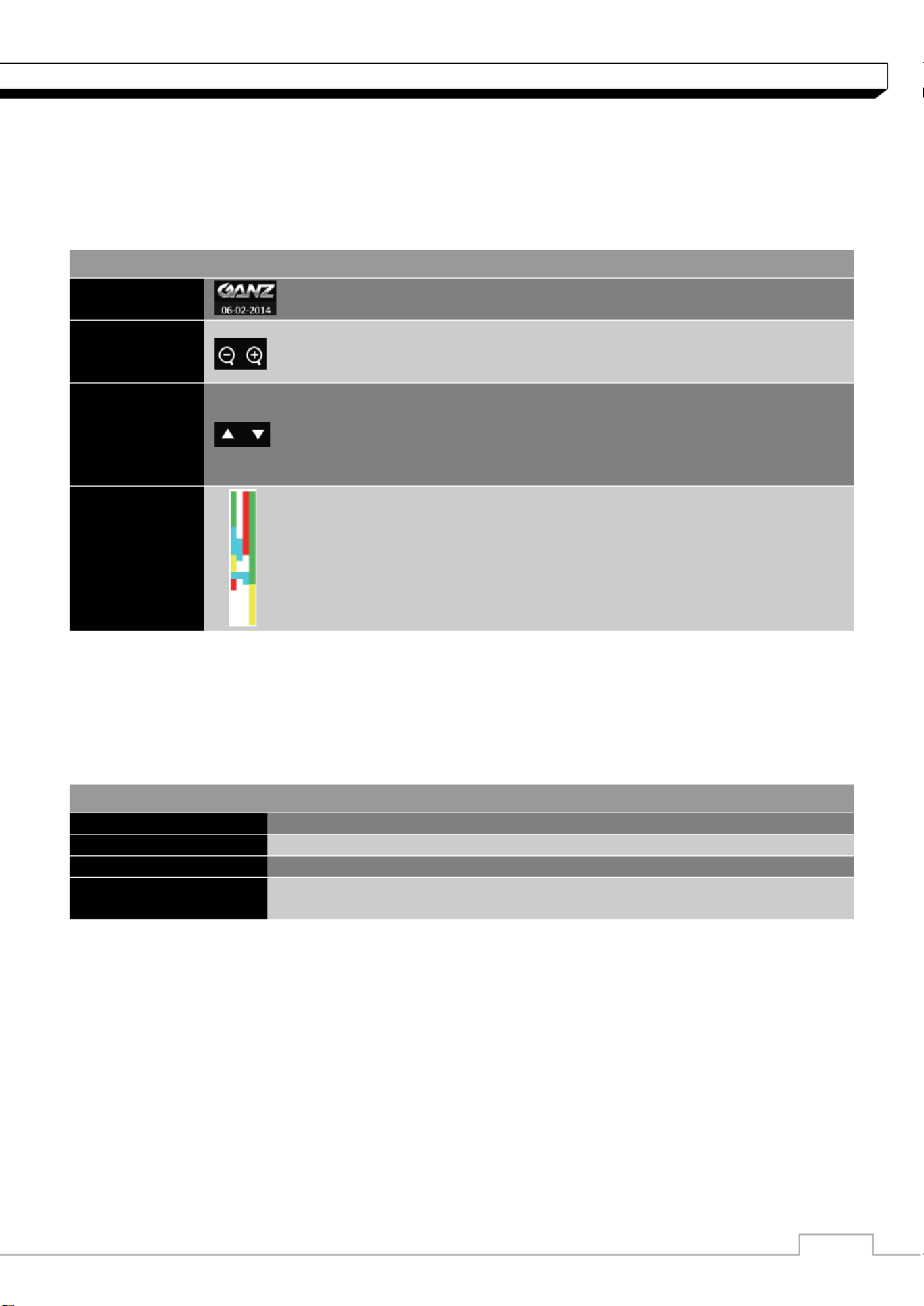
Live Screen At a Glance
The live screen largely consists of three components: video window, status bar and timeline zone.
Video Window
Icons used in the video window.
ITEM
Description
Camera ID
Show the camera ID
Record Mode Icons
Displayed if an event recording is reserved.
Display the status of the continuous recording.
Display the recording status when an alarm occurs.
Display the recording status when a motion event occurs..
Display the status of the emergency recording..
Audio Icon
The audio signal of the connected camera is outputting.
Motion Detection Icon
A motion is detected by the connected camera.
Status Bar
Timeline
Quick Menu
Video Window

6
Monitoring
Status Bar
Press the button on the remote control, or place the mouse in the lower area of the screen to ▼
display the status bar.
ITEM
Description
Menu Button
Select one of the system setup, search and backup menu items
before accessing it.
User ID
Show the ID of the user who has currently logged in.
Screen
Control
Buttons
Change the screen layout so that both status bar and timeline are
displayed at all times.
Select a split mode.
Select Auto Sequence or Special Split Mode.
Display or hide the OSD menu on the screen.
PTZ
Move to the PTZ screen. You can control the PTZ operations of a
PTZ-compliant camera on the PTZ screen.
Zoom
Move to the Digital Zoom.
Quick Log
Display the log list of the recent recording events.
Audio
Channel
Selection
Button
You can use the camera supporting the audio input to listen to the
audio.
Panic Record
Start the panic recording.
Alarm Indicator
Turns on if an event occurs. It does not turn on if no reaction to the
event is yet dened.
Click this to check the information of the event that occurred.
Network
Connection
Status
Check if network connection is made via an external PC or mobile
device. Click this to view the details of the concurrent users and to
check the network connection status. For more information, refer to
"Network Setup". (page ) 40
Disk Space
Show the disk space information. If you have set the disk overwrite
mode, it will be displayed "OW" (Over Write) from the start point of
the overwriting. Click this to view the details of the disk status.
For more information, refer to "Record Setup".
Date & Time
Display the current time and date.
7
Monitoring
Timeline
Press the [ ] button on the remote control or move the cursor to the right of the screen to display ▶
the timeline. Double-click the timeline to move to the video screen. Drag and drop it to make backup
or event search for the specied area.
ITEM
Description
Timeline Date
Display the date of the current timeline.
Click this to select a desired date of the timeline.
Expand/
Collapse
the timeline
Expand or collapse the timeline.
Navigation
through
Timeline
Navigate through the timeline.
You can also use the mouse wheel to do the navigation..
Timeline Bar
Display the recording data with time. The color of each bar indicates
the following:
Green : Continuous Recording
Red : Alarm Recording
Blue : Motion Recording
Yellow: Panic Recording
Quick Menu .
ITEM
Description
Channel No
Display the number of the current channel.
Play
Start playing the video of the selected channel from the specied time.
Zoom
Zoom the video of the selected channel.
Snapshot Capture
Capture the current live video and save it in the jpeg format.
Then, you can save the captured image in the USB device.

8
Monitoring
Using the status bar in the live mode
Selecting a split mode
Click a desired split mode from 1, 4, 9, 6, 8 and 16 split screen. Or press the [DISPLAY] button on
the remote control until a desired split mode is displayed.
4CH DVR model support only 1 and 4 split screen modes.
8CH DVR model does not support 16 split screen modes.
Auto sequence
Click the Sequence button in the status bar, or press button on the remote control to the [SEQ]
perform the specied sequence mode.
You can configure the sequence settings in . <SEQUENCE>
For details, refer to Sequence . (page 35) “ ”
Controlling PTZ
You can control PTZ cameras connected to each channel.
Use the mouse to click PTZ button on the status bar, or
press the button of the remote control to initiate [PTZ]
the predened sequence.
In PTZ mode, use buttons on the screen control PTZ or use and to [ZOOM], [FOCUS]
[PRESET] buttons of the remote control.
Select Preset
Record/Screen Control/ Zoom
Zoom/Focus/Iris Adjustment
Move
SCAN/TOUR
Settings
9
Monitoring
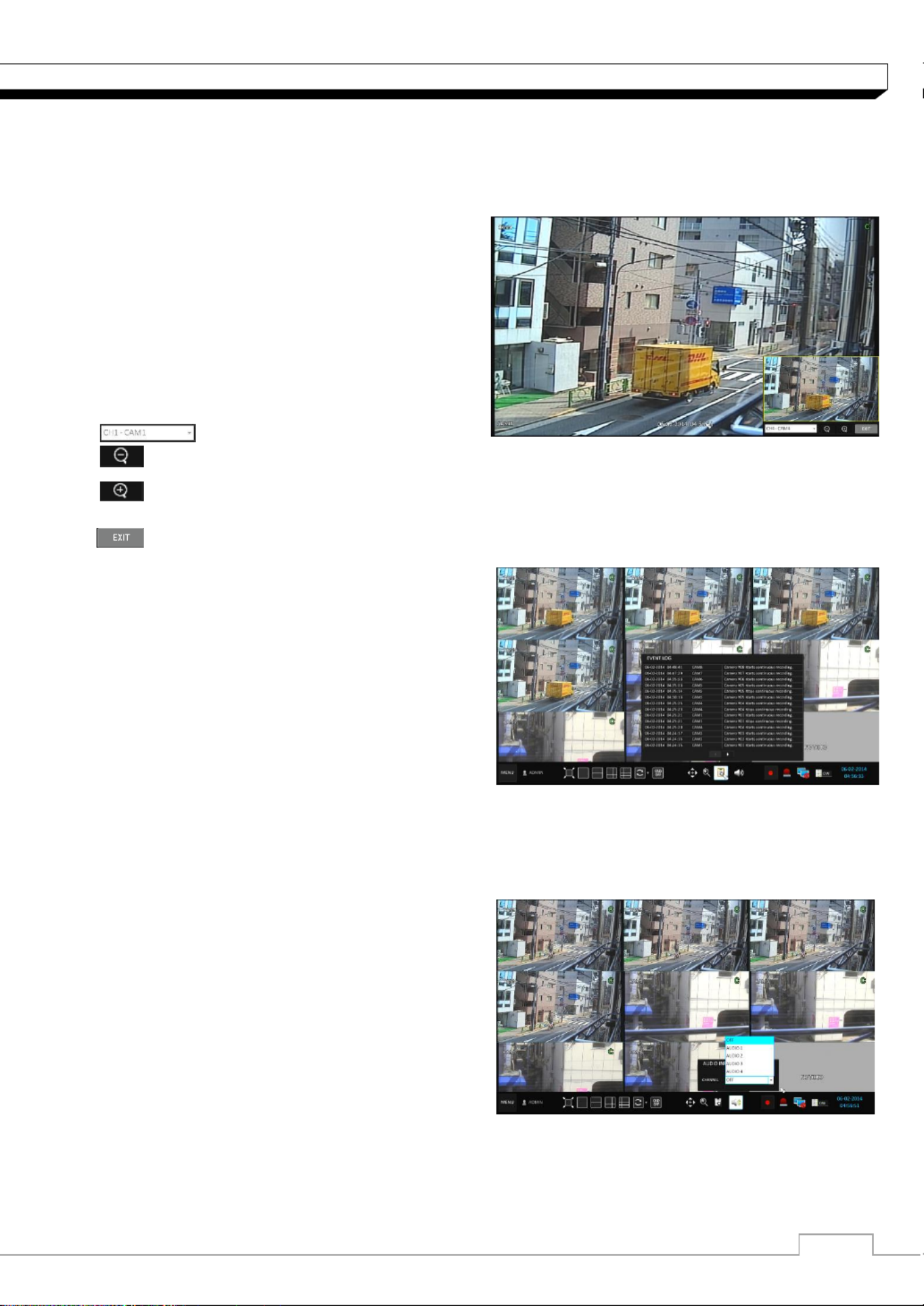
Digital Zooming
You can enlarge the monitoring screen for better view.
Zooming will enlarge the video of the selected channel. If no channel is selected, channel 1 will be
zoomed.
1. Click Zoom in the status bar or move the cursor
to a desired channel and right-click it to display
the . context menu. Select <ZOOM>
You can also press button on the the [ZOOM]
remote control.
2. Move to the zoom control screen. When the
menu bar appears in the right bottom, use the
buttons to control the zooming.
Select a channel to zoom in/out.
Zoom out the current (enlarged) image step by step.
Enlarge the current image step by step.
Zoom Box : Use the yellow box to move to or select a desired zooming area.
Exit the zooming screen and return to the live screen.
To check the event log
You can check the log of the events that occurred.
1. Click Log to display the window. “EVENT LOG”
The log list is sorted with the latest one on top.
2. Double-click a desired log to display the event
video.
You will move to the play screen of the selected
log.
To select an audio input channel
Select a channel from which the audio signal will be received.
>CHANNEL : Produces the selected channel’s
Audio, regardless of the split screen mode.
>LINK TO FULL SCREEN :When switching the
DVR display mode to view one channel, it
Produces the selected channel s audio. ’

10
Monitoring
To check the alarm status
You can check the alarm status of each camera.
Click to close the window <OK>
To check the network status
Shows connection status of camera and network devices.
Click to display detailed information on current users and network connection
Click to close the window. <OK>
For more information, refer to "Network Status".
( page 40).
To check the disk status
You can check the storage space of the current disk
and check also if there is any problem with the disk.
Click to close the window. <OK>
For more information, refer to "Disk Information".
(page 47)

11
Monitoring
Saving captured snapshots
You can capture the current video screen and save or export to a connected storage device.
1. Select a channel rst, and right click to open
pop up menu, and select
<SNAPSHOT CAPTURE>
menu item, or press the
[SNAPSHOT]
button of
the remote control.
2. Connect a storage device, and click <EXPORT>
button. To save the captured image onto the
built-in HDD, press the <RESERVE> button.
Saved image can be found in the “Archive>
Reserved data management” and can be
backed up.
3. Enter the <TAG NAME> <MEMO> <BURN> <ERASE & BURN> and and press or button
> A progress bar appears and indicates the progress of exporting to storage device.
> BURN : Snapshot is stored in the connected USB storage device.
> ERASE & BURN : Deletes all les in the connected USB storage and then saves
the snapshot.
12
System Setting
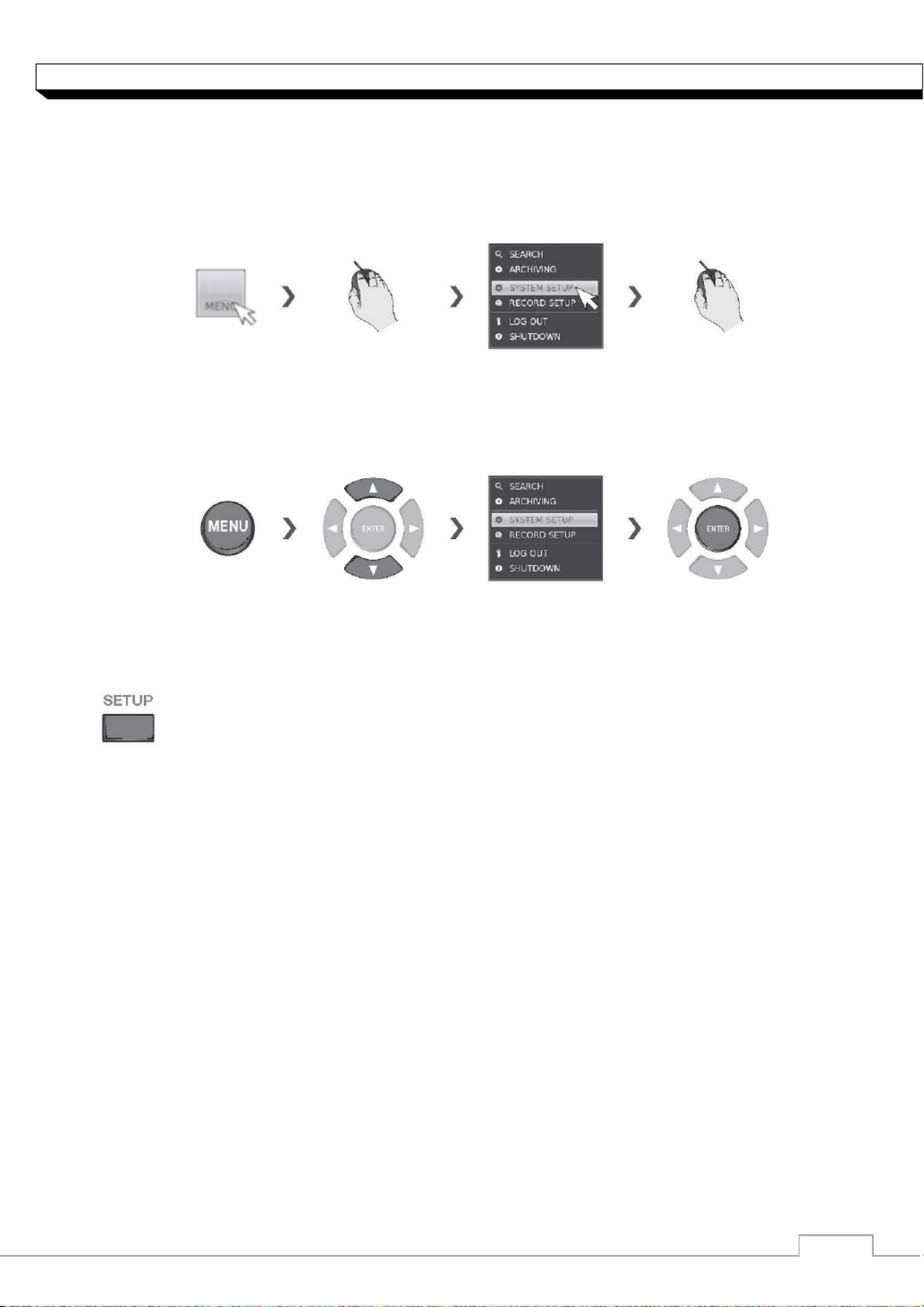
To move to the System Setup menu
How to use the mouse
How to use the remote control 1
How to use the remote control 2
.

13
System Setting
Camera Setting
You can congure the display settings of: camera title, covert option, motion and camera type
CAMERA TITLE
You can change the camera ID that is displayed on
the screen.
1. From <SYSTEM SETUP> <CAMERA>, - select
<CAMERA TITLE>.
2. Use the buttons on the remote [▲▼◀▶/ENTER]
control or use the mouse to select a channel that
you want to rename.
Alternatively, simply double-click the camera to
rename from the top left corner.
3. Once the virtual keyboard appeared, select desired
alphanumeric characters to complete your input,
and press the button. < >OK
The key toggles letter case.<SHIFT>
4. To apply the change, click <APPLY> in the bottom
of the screen.
5. When done, press the button on the remote [EXIT]
control or click button. <CLOSE>
The conrmation message appears and you will return to the previous menu.
Camera title allows up to 16 letters, combining numbers and upper/lower case alphabets.
Image Setup
You can adjust brightness, contrast, color and quality setting of each channel s camera. ’
1. From <SYSTEM SETUP> <CAMERA>, <IMAGE SETUP - select >.
2. Use the buttons on the remote [▲▼◀▶/ENTER]
control or use the mouse to set each option of the
image menu.
3. To apply your changes, click <APPLY> button.
4. Once completed with setup, press button of [EXIT]
the remote control or click button on the <CLOSE>
bottom of the screen. A conrmation dialog appears
and returns to the previous menu.
Press <PREVIEW> button for adjusting with preview image.

14
System Setting
Crop Setting
You can cut out unnecessary region of channel s video. ’
1. From <SYSTEM SETUP> <CAMERA> - , select
<IMAGE SETUP>-<CROP SETTING>.
>CHANNEL : Select the channel to set cropping
area.
>OPERATION : Set whether to use cropping or not.
>BOX COLOR : Select the box color to mark the
cropping area.
>BOX POSITION : Set position and size of the
cropping box.
2. To apply the change, click <APPLY> button.
3. When done, press the button on the remote control or click button. [EXIT] <CLOSE>
The conrmation message appears and you will return to the previous menu.
Covert Setup
You can set to hide the camera video so that
a specic user or user group cannot view.
Set a channel(s) that you want to hide from a specic
user or user group.
1. From <SYSTEM SETUP> <CAMERA> - , select
<COVERT SETUP>.
2. Use the buttons on the remote /ENTER][▲▼◀▶
control or use the mouse to select a covert
channel(s) from a specic user group.
>ADMIN, MANAGER, USER : Set them to . <ON>
The selected channel will be hidden from the applicable user account.
>LOGOUT : Set it to . When the user logs out, selected channel will not be displayed. <ON> the
3. Select display title on live view screen for covert channel either COVERT or NO VIDEO “ ” “ ”
To activate this settings, user need to logo then login DVR again.
4. To apply the change, click <APPLY> button.
5. When done, press the button on the remote control click button. [EXIT] or <CLOSE>
The conrmation message appears and you will return previous menu. to the
To change the covert settings from user group to user, move to the menu and make <USER>
necessary changes. (page ) 38
15
System Setting
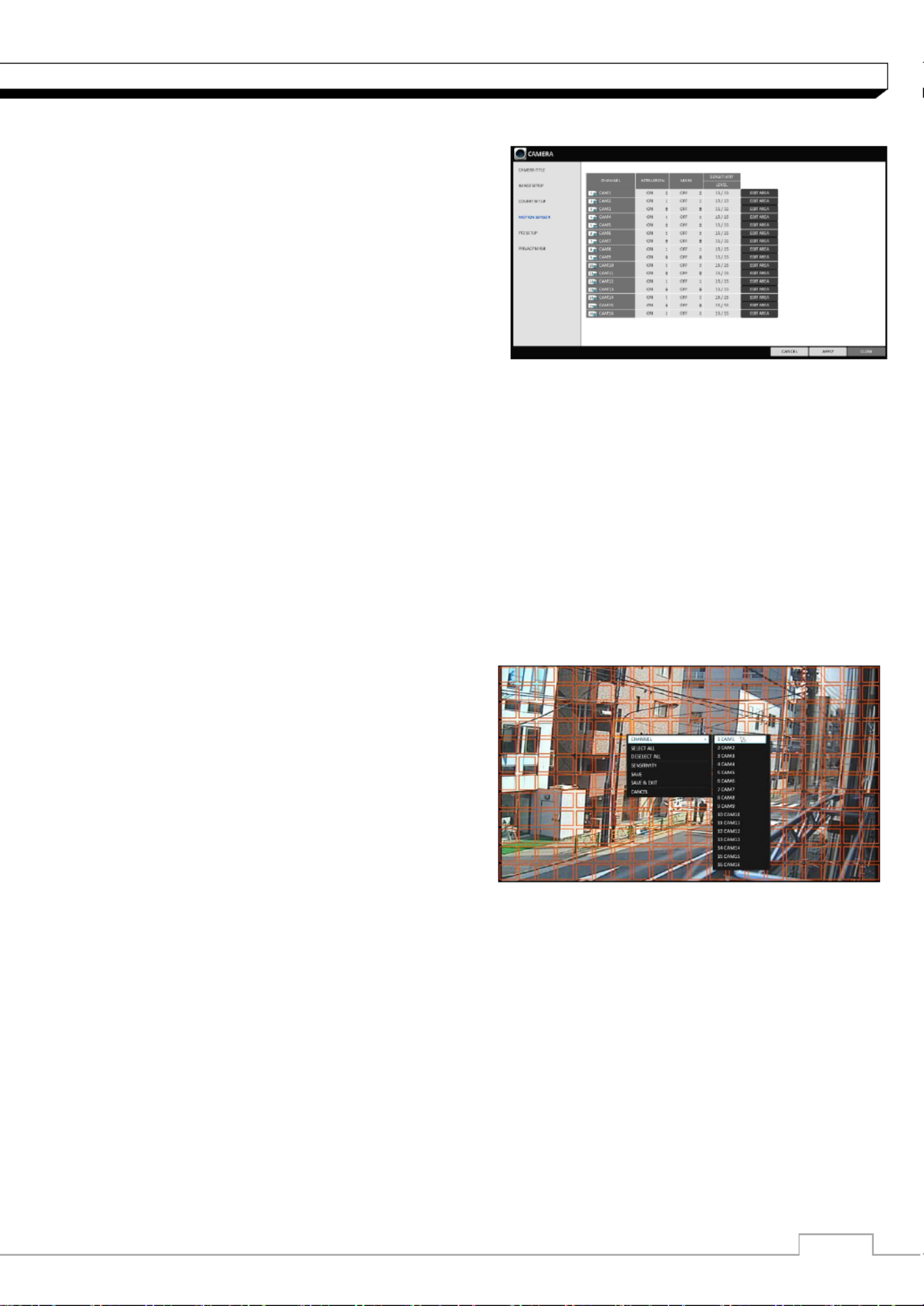
Motion Sensor
Set the motion sensor of the camera so that it can
detect a motion event.
1. From <SYSTEM SETUP> <CAMERA> - , select
<MOTION SENSOR>.
2. Use the buttons on the remote [▲▼◀▶/ENTER]
control or use the mouse to specify the use of each
option item.
> ACTIVATION : turn on or o the motion sensor.
> MOTION MARK: Set it to <On>.
The video window will display the motion mark if a motion is detected.
> SENSITIVITY : Set the sensitivity level of the motion sensor to either Daytime or Nighttime.
> EDIT AREA : Specify the motion detection area.
3. To apply the change, click <APPLY> button.
4. When done, press the button on the remote control or click button. [EXIT] <CLOSE>
The conrmation message appears and you will return to the previous menu.
The motion detection sensitivity may dier depending on the characteristics of the
connected camera or installation environment.
Motion Area Setup
From the motion setup window, click in the right corner. <EDIT AREA>
1. Click to move to the motion <EDIT AREA>
area setup screen.
2. If using the remote control, press the [ENTER]
to mark the current position. button
3. Use the arrow buttons to move to a desired block
and press . The area setup will begin. [ENTER]
Then, use the arrow buttons to specify the area.
Alternatively, you can use the drag-and-drop
method to specify or release the area using
mouse.
4. If you select the specified area again, it will be released.
5. Press the button on the remote control or [EXIT]
right-click any area to display the popup window
as in the right picture.

16
System Setting
6. While the popup window is displayed select ,
<SENSITIVITY> to set the detection sensitivity.
> CHANNEL : select a channel to set the motion
Sensitivity.
> SENSITIVITY : 1(Low) ~ 15(High) - The higher
the number is, the more higher the sensitivity
level becomes.
> DAYTIME Specify the time period that will be :
considered as daytime.
- DAYTIME : specify the for the daytime. <SENSITIVITY>
- NIGHTTIME : specify the for the nighttime. <SENSITIVITY>
Images recorded in a low contrast scene such as at night cause severe noise, triggering the
motion event too often.
If unwanted events occur frequently at night, you may want to reduce the motion
sensitivity for the night duty.
PTZ Setup
You can congure PTZ cameras connected to each channel. Set the camera ID, protocol, baud rate
and PTZ control speed for each channel.
1. From - , select . <SYSTEM SETUP> <CAMERA> <PTZ SETUP>
2. orUse the buttons on the remote [▲▼◀▶/ENTER]
mouse to set protocol and baud rate.
Refer to user s manual of the PTZ the camera’
or consult camera installer for further details
on PTZ settings, such as camera address,
protocol and baud rate.
3. button.To apply your changes, click <APPLY>
4. Once the setup completed, press the [EXIT]
button of the remote control or click button <CLOSE>
on a conrmation dialog. Click <CANCEL> to return to the previous menu.
17
System Setting
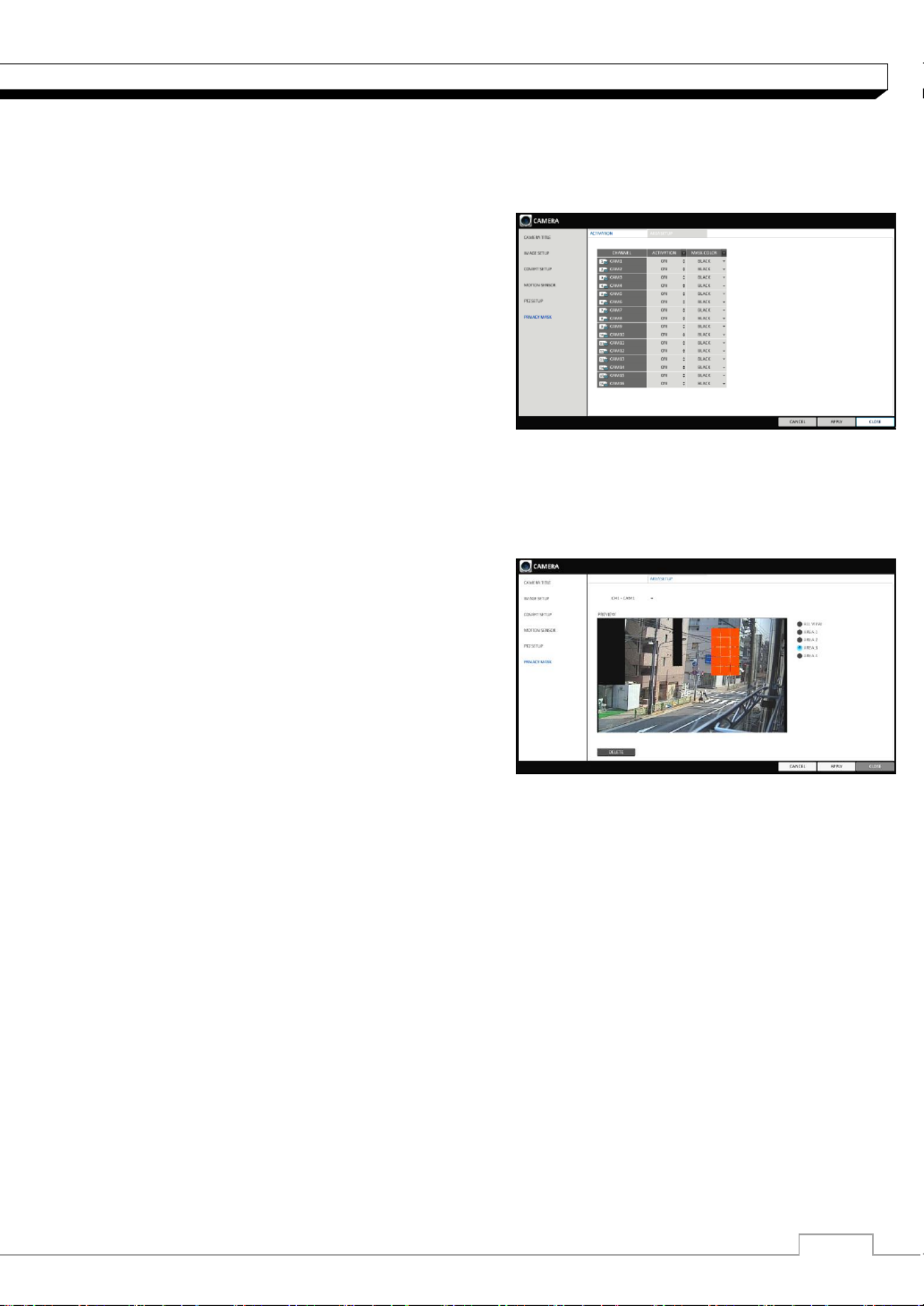
Privacy Mask
For privacy purposes, you n specify masking area for a selected cameraca ’s video.
1. From - , select . <SYSTEM SETUP> <CAMERA> <PRIVACY MASK>
2. orUse the buttons on the remote [▲▼◀▶/ENTER]
mouse to set channels enabled, mask color and
its area.
> ACTIVATION Turn on or o the privacy mask. :
> MASK COLOR Select the color of the masked :
area, which will be displayed on the monitor.
3. button.To apply your changes, click <APPLY>
4. When done, press the button on the remote [EXIT]
control or click button. <CLOSE>
Privacy Mask Area Setup
You n specify privacy masking area. ca
1. From tab on the right side. <AREA SETUP>
2. When using the remote, press the [Select]
to show the selector rst. button
3. Use direction key to move to the desired channel,
and the press the button to begin area [Select]
setup.
Use direction keys to set the masking area.
When using mouse, hold the mouse left button
and drag to set or cancel the masking area.
4. Selecting masked area again will exclude the
corresponding block from the masking area.

18
System Setting
Tamper Detection (Available on -8/16FX5)DR
You can set to detect tampering attempt to interfere monitoring operations by tampering the installed
camera.
1. Select the form the <TAMPER DETECTION>
menu items in . <CAMERA> <SYSTEM SETUP>
2. Use the buttons on the remote or the [▲▼◀▶/]
mouse to select and <MARK, SENSITIVITY>
set the tampering detection condition appropriately.
3. For each channel, set the day/night sensitivity.
4. Set the activation of each channel, and set whether to display indicator on the screen.
>SENSITIVITY
-LEVEL : The detection sensor s sensitivity for ’
each detection block. (Can be separately set
for day/night modes)
> ACTIVATION Set the detection for each :
channel to be enabled/disabled.
> MARK : Turns on or o the detection indicator
to be displayed on the screen
5. To apply your changes, click . <APPLY> button
6. When done, press the [EXIT] button on the remote control or <CLOSE> in the lower screen.
The conrmation message appears and you will return to the previous menu.

19
System Setting
Display Setting
You can configure the display settings regarding the OSD, sequence monitor and SPOT output.
OSD
You can set Camera Name, Icon, Status Bar, Timeline, Borderline, User Name and Language
1. From <SYSTEM SETUP> - <DISPLAY>,
select . <OSD>
2. Use the buttons on the remote /ENTER][▲▼◀▶
control or use the mouse to set each option of the
OSD item.
> CAMERA TITLE : specify the display of the
camera title on the screen.
> RECORDING MODE ICON : specify the display
of the record mode icon on the screen.
> AUDIO ICON : specify the display of the audio
icon on the screen.
> STATUS BAR ON FULL SCREEN MODE : select to show or hide the status bar in full screen
mode.
- AUTO HIDE : place the cursor in the lower area of the screen to display the status bar.
If moving the cursor up, the status bar will disappear.
- ALWAYS ON : The status bar will be displayed at all times.
- 5 SEC ~1 MIN : If no mouse movement is detected for from 5 seconds to 1 minute, the status
bar will disappear.
> TIMELINE ON FULL SCREEN MODE : select to show or hide the timeline in full screen mode.
- AUTO HIDE : place the cursor in the right corner to display the timeline. If moving the cursor to
the left, the timeline will disappear.
- ALWAYS ON : The timeline will be displayed at all times.
- ALWAYS OFF : The timeline will not be displayed.
> ZOOM PIP Select to show or hide the Picture in Picture window on Digital Zoom. :
-ALWAYS ON : PIP window will be displayed at all time.
-1/3/5 SEC : PIP window will disappear after selected time.
> BORDER LINE : specify the display of the cross-border between channels in a split mode
> BORDER COLOR : select a color for the border.
> USER NAME : specify the display of the currently logged-in users on the status bar.
> LANGUAGE : select a menu display language.
3. To apply the change, click <APPLY> . button
4. When done, press the button on the remote control or click button. [EXIT] <CLOSE>
The conrmation message appears and you will return to the previous menu.

20
System Setting
Monitor
If you change from monitoring mode to sequence, you will have to set the interval of the sequence.
1. From <SYSTEM SETUP> - <DISPLAY>, select
<MONITOR>.
2. Use the buttons on the remote [▲▼◀▶/ENTER]
control or use the mouse to set dwell for sequence
mode and SPOT Out dwell.
> SEQUENCE DWELL : Sets the time interval to
the next screen mode for Live monitoring, which
denes individual screen mode s dwell time in the �
Sequence. (Can set to 1 sec ~ 60 sec)
> SPOT DWELL : Sets the time interval to the next
view type, which defines individual view type s dwell time for SPOT OUT. (Can set to 1 ~ 60sec) ’
> VIDEO ASPECT RATIO : Set aspect ratio for Live View image ( 16:9 / 4:3 ).
> DISPLAY RESOLUTION: Set monitor output resolution.
(Auto / 1920x1080 /1280x720 / 1280x1024)
3. To apply the change, click <APPLY> . button
4. When done, press the button on the remote control or click button. [EXIT] <CLOSE>
The conrmation message appears and you will return to the previous menu.
Sequence
Select a split mode for the sequence, and also select a list of active items when the sequence is
performed.
1. From <SYSTEM SETUP> - <DISPLAY>, select
<SEQUENCE>.
2. Use the buttons on the remote [▲▼◀▶/ENTER]
control or use the mouse to add a sequence or
change the settings of the existing sequence.
>ACTIVATION : Select a list that you want to
activate the sequence for.
Only one list will become active.
>ADD : add a sequence.
3. To apply the change, click <APPLY> button.
4. When done, press the button on the remote control or click button. [EXIT] <CLOSE>
The conrmation message appears and you will return to the previous menu.
To add a sequence
1. Click in the bottom of the screen. <ADD>
2. When the "ADD" dialog appears, enter a title using
the virtual keyboard.
3. Enter the name of the sequence and click . <ADD>
4. When the dialog appears, <ADD VIEW TYPE>
click . <ADD>

21
System Setting
5. a When the dialog appears, select"SEQUENCE SETUP" split mode that you want
. to add from <VIEW TYPE>
6. If the selected split mode is displayed on , select a channel you want <VIEW CONFIGURE>
to display in each split screen.
7. Click . <CONFIRM>
The set sequence mode is conrmed and will be
added to the Add Sequence list in order
8. When done, click in the bottom of the <CLOSE>
screen.
After the sequence type is saved, you will return to
the previous screen.
9. Place your mouse cursor over desired tile of
added sequence, right Right-click on it or press the button on the remote control [ENTER]
to edit or delete it.
To edit a sequence
1. Select a sequence that you want to edit in the list.
2. The "EDIT" dialog appears.
3. Use the buttons on the remote [▲▼◀▶/ENTER]
control or use the mouse to edit the selected
sequence.
>SEQUENCE TITLE : enter a new sequence name.
>ACTIVATION : specify the use of the sequence.
>MODIFY : change the settings of the sequence
mode.
>DELETE : delete the selected sequence list.
>CANCEL : cancel the changes.
4. Pressing the button will display the Edit Sequence window. <EDIT>
5. To change the existing settings, select a screen mode that you want to edit and right-click to
display the context menu. Then, select . <EDIT>
6. When done, click to close the window. <CLOSE>
7. To apply your changes, click <APPLY>.

22
System Setting
SPOT OUT (1U Model)
Apart from the main screen display, you can congure the Spot Out to display a Live channel as
needed in various live view types. You can set the live view type of display output through the
[SPOT] terminal and activate / deactivate it.
1. From - <SYSTEM SETUP> <DISPLAY>,
select . <SPOT OUT>
2. Use button of the remote [▲▼◀▶/ENTER]
control or mouse to edit Spot Out properties.
>SPOT TITLE : Name the Spot Out setup.
>ACTIVATION : Set whether to activate /
deactivate the spot out setup.
>MODIFY : Edit the view type of the spot output.
>SAVE : Save the changes of spot output settings.
3. To apply your changes, click button. <APPLY>
4. Once completed with setup, press button of the remote control or click button [EXIT] <CLOSE>
on the bottom of the screen. A conrmation dialog appears and returns to the previous menu.
To add a View Type to a SPOT OUT
1. Select an item from the SPOT OUT list to be changed.
2. The EDIT window appears, click button. “ ” <EDIT>
3. When the View Type selection window appears,
click button. <ADD VIEW TYPE>
4. Select the desired View Type and conguration,
and click button. < >OK
5. Complete adding and click to close <CLOSE>
edit window. the
9 and 16 split screen mode are available only for 16 channel model.
To edit or delete View type of the SPOT Out
1. Select an item from the SPOT O list to be changed. UT
2. The window appears, click button. EDIT“ ” <EDIT>
3. When the View Type selection window appears,
select the desired View Type to be edited or
deleted, and press button of the remote [ENTER]
control or right click on it.
> MODIFY : Displays window “ ”SPOT SETUP
for editing View Type and other properties.
> DELETE : Deletes the selected View Type.
5. Complete editing and click to close the edit window. <CLOSE>

23
System Setting
SPOT OUT (2U Model)
2U model has two types of SPOT output port.
AUX : Programmable. Support 1/4/9/16 display mode.
SPOT 1-4 : Programmable. Supports 1/4 display mode.
1. orFrom - , select <SYSTEM SETUP> <DISPLAY> <SPOT -16DIVISION>
<SPOT-4DIVISION>.
2. Setting menu is the same as 1U model on
previous page.

24
System Setting
Audio Setup
Choose whether to receive the live sound source and select an audio channel.
1. From <SYSTEM SETUP> - <AUDIO> <AUDIO>, select .
2. Use the buttons on the remote [▲▼◀▶/ENTER]
control or use the mouse to select an item that
you want to edit.
>DEFAULT LIVE AUDIO CHANNEL : select an
Audio channel to monitor on the live screen.
>NETWORK AUDIO TRANSMISSION : decide if
DVR transfers the audio signal to the remote client.
DVR PC(Remote client)
>RECEIVE NETWORK AUDIO : decide if DVR
receives the audio signal from the remote client.
PC(Remote client) DVR
3. To apply the change, click <APPLY>button.
4. When done, press the button on the remote control or click button [EXIT] <CLOSE> .
The confirmation message appears and you will return to the previous menu.
Buzzer output
You can set to output the buzzer if you manipulate the remote control.
1. From <SYSTEM SETUP> - <AUDIO>, select
<BUZZER>.
2. Use the buttons on the remote [▲▼◀▶/ENTER]
control or use the mouse to select an item that you
want to edit.
> REMOTE CONTROL : specify the output of a beep
when you press a button on the remote control.
3. To apply the change, click <APPLY> button/
4. When done, press the button on the remote control or click button. [EXIT] <CLOSE>
The confirmation message appears and you will return to the previous menu.

25
System Setting
User Setting
You can configure the settings regarding user management and user and group permissions.
Management
You can add a user account(s) that can be edited at a later time.
1. From <SYSTEM SETUP> - <USER>, select
<MANAGEMENT>.
2. Use the buttons on the rem [▲▼◀▶/ENTER] ote
control or use the mouse to add a user account or
select an item that you want to edit.
3. To apply the change, click <APPLY> in the bottom
ofthe screen.
4. When done, press the button on the remote [EXIT]
control or click in the lower screen. <CLOSE>
The confirmation message appears and you will return to the previous menu.
To add a user account
1. Click in the bottom of the screen. <ADD>
2. Use the buttons on the remote control and [▲▼◀▶]
move to a desired item. Then, press [ENTER] to
select the item.
> USER ID : enter the user ID using the virtual
keyboard.
> PASSWORD : With the virtual keyboard, enter the
password.
> GROUP : From d <ADMIN>, <MANAGER> an
<USER>, select a group that the user belongs to.
> EMAIL : Type in the e-mail address to which you will receive notification of an event if it occurs.
> EMAIL NOTIFY : Choose whether you will receive notification of an event if it occurs.
To use <EMAIL NOTIFY>, a send mail server and its port should be configured previously.
> COVERT CHANNEL : You can set the channel to hide from a specific user.
< COVERT CHANNEL >, option hides the video of the selected channel from being
displayed on the screen.
3. When done, click . The added user account will be listed. <OK>

26
System Setting
To edit the user account information
1. From the list of users, select a user account to edit
and click next to it. <EDIT>
2. From the Edit window, make necessary changes
and click . <OK>
3. To delete the user account, click . <DELETE>
The account cannot be changed<ADMIN>
or edited
Group Authority
You can grant dierent user groups dierent permissions to a specic menu.
1. From <SYSTEM SETUP> - <USER> <GROUP AUTHORITY>, select .
2. Use the buttons or use the [▲▼◀▶/ENTER]
mouse to set the permissions for both
<MANAGER> <USER>and groups.
>SEARCH : Set the permissions for the Search menu.
>ARCHIVING : Set the permissions for the Backup
menu.
>SYSTEM SETUP : Set the permissions for the
System Setup menu.
>RECORD SETUP : Set the Access Permissions for the Record Setup menu.
>EVENT ACTION CONTROL : Set the permissions to output the alarm or control the buzzer if an
event such as alarm occurs.
>LISTEN TO AUDIO : Set the permission to listen to the audio.
>REMOTE LOG IN : Set the permission to access remotely.
>SHUTDOWN : Set the permission to shut down DVR from the System menu.
The <ADMIN> account is the master account allowed for all permissions, which is not edited
for individual permissions.
3. To apply the change, click <APPLY> in the bottom of the screen.
4. When done, press the button on the remote control or click button [EXIT] <CLOSE> .
The conrmation message appears and you will return to the previous menu.

27
System Setting
Network Setup
You can set IP address, DDNS and E-mail settings, and check network status.
IP Setup
Specify the IP address as well as the remote service port.
1. From <SYSTEM SETUP> - <NETWORK>,
select . <IP SETUP>
2. Use the buttons on the remote [▲▼◀▶/ENTER]
control or use the mouse to specify each item of the
network settings.
>DHCP : If it is checked, set the IP address of the
DVR to Dynamic IP.
For DHCP address allocation, the DVR should be
connected to a network environment such as router that provides with DHCP server.
3. Deselect DHCP option to enable manual static address configuration. service.
>IP ADDRESS : Provide the IP address.
>GATEWAY : provide the gateway address.
>SUBNET MASK : provide the subnet mask address.
>1ST DNS SERVER : Enter the address of the primary DNS server.
>2ST DNS SERVER : Enter the address of the primary DNS server.
>RTSP SERVICE PORT : port number that the remote client receives the DVR video from.
>WEB SERVER PORT : port number used for connecting to the DVR with the web browser.
>PORT FORWARDING : If you are using a router, you can set the port forwarding so that external
access to the DVR is enabled.
If the router does not support the uPnP protocol, you must set the port forwarding manually.
For more information, contact your network administrator.
>DELETE PORT : release the port forwarding settings for the router.
>MAX TX SPEED : Limit the network transfer rate to access a remote client.
The video signal may be transferred at a less rate than specified, which depends on the status of
your network connection.
4. To apply the change, click <APPLY> button.
5. When done, press the button on the remote control or click button. [EXIT] <CLOSE>
The confirmation message appears and you will return to the previous menu.

28
System Setting
DDNS
You can configure the DDNS settings so that remote users who are connected to the network can
access remotely.
is an IP redirection service in a dynamic IP environment that redirects (maps) the new DDNS
IP address to a registered domain name each time the IP address is changed.
1. From <SYSTEM SETUP> - <Network>, select
<DDNS>.
2. Use the buttons on the remote [▲▼◀▶/ENTER]
control or use the mouse to specify the use of DDNS
and select a server.
>DDNS : Specify the use of DDNS connection.
>DDNS SERVER : Select a server to connect to.
>DVR NAME : Enter the name of the DVR that you
want to use as DDNS.
>DDNS REGISTRATION TEST : Check if the <DVR NAME> can be set as DDNS. If there is a
duplicate name in the server, the registration will fail. If this is the case, rename the
<DVR NAME> and press Test to check if it works properly.
>DVR ADDRESS : Provide the and press the<DVR NAME> <DDNS REGISTRATION
TEST> button. The name will be added automatically.
>DDNS CONNECTION TEST : Perform the connection test to check if DDNS is normally
registered.
3. To apply the change, click <APPLY> in the bottom of the screen.
4. When done, press the button on the remote control or click in the lower [EXIT] <CLOSE>
screen. The confirmation message appears and you will return to the previous menu.
Email
You can register and test an email address so that an email notification is delivered at a specific
interval or if an event occurs.
1. From <SYSTEM SETUP> - <NETWORK>,
select . <EMAIL>
2. Use the buttons on the remote [▲▼◀▶/ENTER]
control or use the mouse to specify the use of email
and select a server.
>SERVER : Set up the mail server. Set the mail
Server that will be used for notification to the DVR.
>PORT : Enter the mail server port.
>SECURITY : If it is set to , the email will be transferred in secure mode. <On>
If it is set to , the email will be transferred to a server that does not support SSL. <Off>
>USER : Provide the email account (ID) of the sender.

29
System Setting
>PASSWORD : Provide the password of the sender.
>TEST EMAIL ADDRESS : Enter an email address for the test purpose.
>TEST : Send a test email and check if the test email is delivered normally.
3. To apply the change, click <APPLY> in the bottom of the screen.
4. When done, press the button on the remote control or click in the lower [EXIT] <CLOSE>
screen. The confirmation message appears and you will return to the previous menu.
Network Status
From the network map screen, you can check the internet connection status and camera connection
status, and Check also the details of the connection status for each camera.
1. From <SYSTEM SETUP> - <NETWORK> <NETWORK STATUS>, select .
2. When done, press the button on the [EXIT]
remote control or click <CLOSE> button.
The confirmation message appears and you will
return to the previous menu.
Network status
> IP ADDRRESS : Indicates the internal IP address
of the DVR.
> MAC ADDRESS ndicates the internal MAC : I
address of the DVR.
>DDNS ADDRESS Indicates the internal DDNS address of the DVR. :
>RTSP SERVICE PORT : Indicates the network port of the video service.
For remote service, the router must have set up the port forwarding .
>WEB SERVICE PORT : Indicates the web service network port.
For the remote service to be enabled, the corresponding port of the router should have set
up the port forwarding.
> NS UPDATE STATUS Shows if the DDNS address was registered to the DDNS server DD :
normally. Press < > to try to register the DDNS address forcibly.
>EXTERNAL IP ADDRESS : Indicate the IP address for the internet, accessible from the DVR .
T DVR can be granted access with the web browser at http://<External IP Address>:<Web he
Service Port>. The IP address can vary in a dynamic IP environment.
>CONNECTED CLIENTS :Shows the list of clients that are currently connected.
Press < > to terminate the connection of an unwanted client forcibly.
Termination is limited to only users in a lower group than the current user.
30
System Setting
System Setting
You can configure the settings of date/time, system management, and keyboard controller.
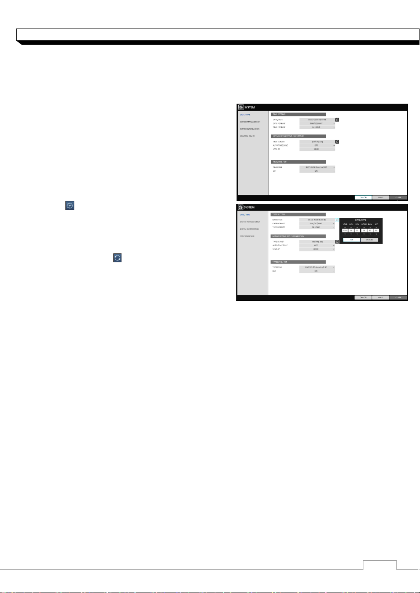
Date/Time
Specify the current date and time.
1. From <SYSTEM SETUP> - <SYSTEM>, select
<DATE/TIME>.
2. Use the buttons on the remote [▲▼◀▶/ENTER]
control or use the mouse to change the time or set
the options as necessary.
>DATE/TIME : Set the current time and date.
Click< > to adjust the time manually.
>DATE FORMAT : specify the date format.
>TIME FORMAT : specify the time format.
>TIME SERVER : obtain the current time from the
time server. Click < > to get the current time.
>AUTO TIME SYNC : automatically synchronize the
time with the time server at a specific time.
>SYNC AT : Set the time to sync with the time server.
>TIMEZONE : specify the GMT standard time for your local area.
>DST : You can set up or release the DST (Daylight Saving Time).
Both and <TIME SERVER> <AUTO TIME SYNC> will be enabled only if the DVR is
connected to the Internet.
3. To apply the change, click <APPLY> in the bottom of the screen.
4. When done, press the button on the remote control or click in the lower [EXIT] <CLOSE>
screen. The confirmation message appears and you will return to the previous menu.

31
System Setting
System Management
You can check, update or reset the system information.
1. From <SYSTEM SETUP> - <SYSTEM>, select
<SYSTEM MANAGEMENT>.
2. Use the buttons on the remote [▲▼◀▶/ENTER]
control or use the mouse to set each option of the
system management.
>FW UPDATE : you can update the current software
with the latest version.
>FACTORY DEFAULT : Return the DVR settings to
the factory default.
If you proceed with the firmware upgrade or
select to reset to the factory default, all current
settings of the DVR will be erased.
In such a case, you must configure the network,
time and recording settings again.
>SYSTEM DATA : Save the system settings or get
the system information from other device.
- SAVE : Store the DVR settings to a storage device.
Connect the storage device to the USB port of DVR.
- LOAD : Apply the settings of the storage device
to the DVR. Connect the storage device to the
USB port of DVR.
>PASSWORD : Open or close the dialog box for
settings of the menus: quit, system settings, record
settings, backup, and search.
If it is set to note that the ADMIN account<Off>,
is only effective and access to all menus will be
restricted.
>EXPIRED TERM OF PASSWORD : You will be
prompted to change the current password after a
certain period of time.
>AUTO LOGOUT : If there is no user input for a certain period of time, you can set to log out
automatically.
>WAIT TIME : Specify the waiting time for Auto Logout.
3. When done, press the button on the [EXIT]
remote control or click in the lower screen to return to the previous menu. <CLOSE>

32
System Setting
To perform the upgrade
1. Connect the USB storage device that contains the
updatable files.
2. Click . <USB>
3. Select one(s) from the updatable files LIST listed
in . <F/W >
4. Click . <UPGRADE>
5. When the confirmation message appears, click
. <OK>
6. The progress bar displays the progress of the
firmware upgrade process.
7. When the upgrade is complete, reboot the system.
During the updating, never turn off the DVR
forcibly or disconnect the USB storage device
to avoid serious damage to the product or data.
If required, consult your nearest service center
for professional assistance.

33
System Setting
System Information
You can check the current system version and system-related settings.
1. From <SYSTEM SETUP> - <SYSTEM>,
Select <SYSTEM INFORMATION>.
2. Check the status of the current system.
3. When done, press the button on the [EXIT]
remote control or click button. <CLOSE>
Control Device
Configure the settings of the remote control and
keyboard controller.
1. From <SYSTEM SETUP> - <SYSTEM>, select
<CONTROL DEVICE>.
2. Use the buttons on the remote [▲▼◀▶/ENTER]
control or use the mouse to set the connection
options for the control device.
>SYSTEM ID : Set the ID of the DVR so that the
keyboard controller can identify.
>PROTOCOL : Set up the protocol of the keyboard
controller.
>BAUD RATE : Specify the RS485 communication speed.
>REMOTE CONTROLLER ID : Set the ID of the remote control.
3. To apply the change, click <APPLY> in the bottom of the screen.
4. When done, press the button on the remote control or click in the lower [EXIT] <CLOSE>
screen. The confirmation message appears and you will return to the previous menu.

34
System Setting
Stora ge
You can configure the settings of and view information of the disk and external storage device.
2U model (DR8/16FX5) supports both <INTERNAL> and <EXTERNAL STORAGE>.
Disk Information
It will show information about the connected disk.
1. From <SYSTEM SETUP> - <STORAGE>,
select <DISK INFORMATION>.
2. Use the buttons on the remote [▲▼◀▶/ENTER]
control or use the mouse to check each connected
peripherals.
>START / END TIME : show the start time and end
time of data stored in each disk.
>STATUS : check if the connected disk is being
used by the DVR. If you encounter a problem with
the disk, the DVR will terminate the connection to
the disk and mark it as Not In Use . ‘ ’
>CAPACITY : show the capacity of the disk.
>MODEL : indicate the disk model.
>S.M.A.R.T STATUS : Read the S.M.A.R.T
information of the disk and check to display if the
current disk is in normal operation.
- NORMAL : The disk is in a normal state.
- CHECK : The disk has an error so that you need to check the disk or the connection cables of
the disk. If you leave the problem unresolved, no recording may be enabled.
So it is recommended that you replace the disk immediately.
- ERROR : The disk fails or is unable to use due to an error of the disk or the cable.
The disk should be replaced immediately. Contact the retailer or the customer service to
replace the disk.
3. When done, press the button on the remote control or click in the lower [EXIT] <CLOSE>
screen to return to the previous menu.
35
System Setting
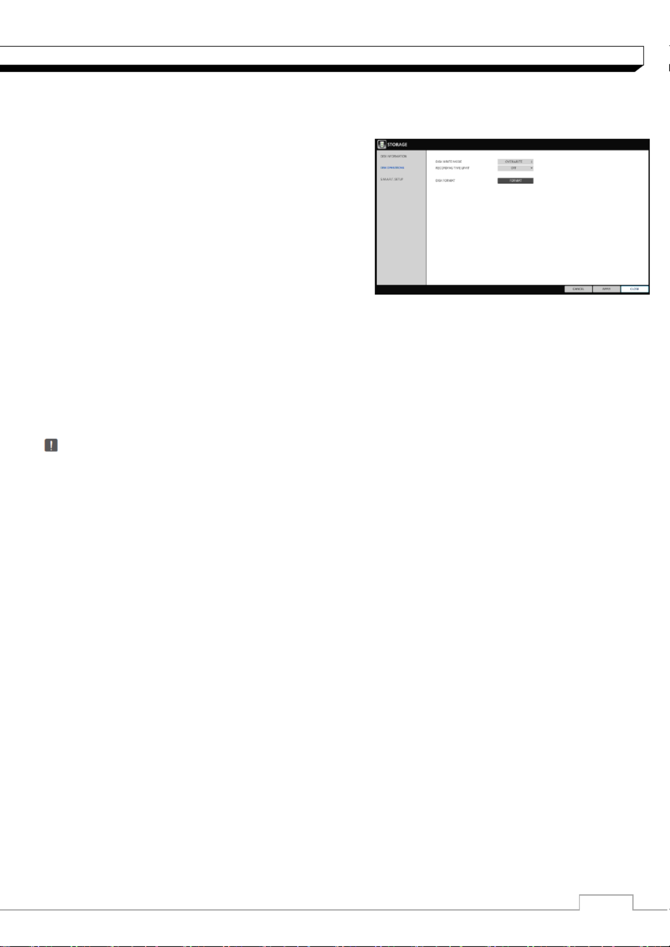
Disk Operations
You can set to delete the recording automatically and set the overwrite options, and you can also
format the HDD recording data.
1. From <SYSTEM SETUP> - <STORAGE>,
select <DISK OPERATIONS>.
2. Use the buttons on the remote [▲▼◀▶/ENTER]
control or use the mouse to set the operation
conditions of the disk.
>DISK WRITE MODE
- If it is set to <OVERWRITE>, the existing data
will be overwritten by new recording data if the
recording data size exceeds the free space of the HDD.
- If the option is set to and the HDD is full, the DVR will stop recording and output the <ONCE>
beep or alarm that is pre-defined at . <EVENT>
>RECORDING TIME LIMIT : The recording data will be deleted after a specific time of reservation.
If it is set to , this function will be disabled. <OFF>
>DISK FORMAT : format the hard disk.
Note that formatting the HDD will delete all video data and logs.
3. To apply the change, click <APPLY> in the bottom of the screen.
4. When done, press the button on the remote control or click button. [EXIT] <CLOSE>
The confirmation message appears and you will return to the previous menu.

36
System Setting
S.M.A.R.T settings
You can check the S.M.A.R.T information of the disk and specify the check frequency.
What is S.M.A.R.T information?
S.M.A.R.T (Self-Monitoring, Analysis and Report Technology) is to detect a HDD that is likely to
cause a problem in the future with a warning message.
2U model (DR8/16FX5) supports both <INTERNAL> and <EXTERNAL STORAGE>.
1. From <SYSTEM SETUP> - <STORAGE>,
select <S.M.A.R.T. SETUP>.
2. Use the buttons on the remote [▲▼◀▶/ENTER]
control or use the mouse to check the S.M.A.R.T
operation and specify the check interval.
>S.M.A.R.T STATUS : Read the S.M.A.R.T
information of the disk and check to display if the
current disk is in normal operation.
Click <DETAIL INFO> to view the details.
- NORMAL : The disk is in a normal state.
- CHECK : The disk has an error so that you need
check the disk or the connection cables of the to
disk. If you leave the problem unresolved, no
recording may be enabled.
So it is recommended that you replace the disk
immediately.
- ERROR : The disk fails or is unable to use due to
an error of the disk or the cable.
The disk should be replaced immediately.
Contact the retailer or the customer service to replace the disk.
S.M.A.R.T CHECK INTERVAL : Specify the S.M.A.R.T check interval. Click <CHECK NOW>
to start checking.
3. To apply the change, click <APPLY> in the bottom of the screen.
4. When done, press the button on the remote control or click button. [EXIT] <CLOSE>
The confirmation message appears and you will return to the previous menu.

37
System Setting
Event Setup
Define various events, and specify the conditions to notify the user in various ways.
Alarm Out
Specify the alarm output conditions with the work schedule.
Number of alarm output is different on each models.
Model
Relay output
Alarm (TTL) output
DR-4FX1
1
N/A
DR-8FX2
1
N/A
DR-16FX2
1
N/A
DR-8FX5
4
4
DR-16FX5
8
8
1. From <SYSTEM SETUP> - <EVENT>, select
<ALARM OUT>.
2. Use the buttons on the [▲▼◀▶/ENTER]
remote control or use the mouse to select
and configure the related settings. <ALARM OUT>
>NAME : You can rename the alarm.
>OPERATION : Set the alarm output mode.
- N/O (Normal Open) : It normally stays Open.
If an event occurs, it will switch to Close.
- C (Normal Close) : It normally stays Close. N/
If an event occurs, it will switch to Open.
>DURATION : Specify the duration of the alarm output.
- TRANSPARENT : Keep the alarm out for as much time as the event lasts.
- UNTIL KEY : Keep the alarm out until a mouse or remote control button is pressed.
- 5 ~ 300 SEC : Keep the alarm out for as long as specified.
>TEST : Forcibly output the alarm for the test purpose.
3. To apply the change, click <APPLY> in the bottom of the screen.
4. When done, press the button on the remote control or click button. [EXIT] <CLOSE>
The confirmation message appears and you will return to the previous menu.
38
System Setting
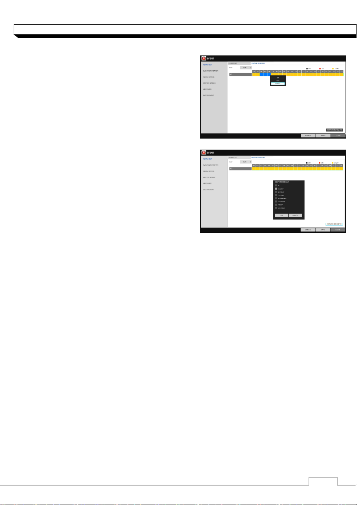
ON/OFF Schedule
You can activate or turn off the alarm output as
scheduled.
1. Use the buttons on the remote [▲▼◀▶/ENTER]
control or use the mouse to select a <DATE> for
schedule. the
2. Drag the mouse to resize the cell or use the on the
buttons to move to the cell, then press [▲▼◀▶]
. [ENTER]
3. Select a desired alarm output mode.
>ON : The alarm output is always turned on.
>OFF : The alarm output is always turned off.
>EVENT : Trigger the alarm output in sync with the
event.
4. Click <COPY SCHEDULE> to check the checkbox
of the date that you want to copy the schedule at.
5. When done, click to apply the settings. <OK>
6. To apply the change, click <APPLY> button.
7. When done, press the button on the remote control or click button.[EXIT] <CLOSE>
The confirmation message appears and you will return to the previous menu.
Event Notification
Specify the methods of notification such as buzzer, video popup or email if an event occurs.
1. From <SYSTEM SETUP> - <EVENT> <EVENT NOTIFICATION>, select .
2. Use the buttons on the remote control or use the mouse to select one from [▲▼◀▶] <BUZZER>,
<DISPLAY> <EMAIL> and .
3. Use buttons on the remote control or use the mouse to set the output the [▲▼◀▶/ENTER]
method and duration.
4. To apply the change, click <APPLY> in the bottom of the screen.
5. When done, press the button on the remote control or click button. [EXIT] <CLOSE>
The confirmation message appears and you will return to the previous menu.

39
System Setting
Buzzer output
You can notify the user of the event using the buzzer.
>DURATION
- TRANSPARENT : Keep the buzzer out for as
much time as the event lasts.
- UNTIL KEY : Keep the buzzer out until a mouse
or remote control button is pressed.
- 5 ~ 300 SEC : Keep the buzzer out for as long
as specified.
Display
If an event occurs, you can display the video screen or a popup message to notify the user.
>VIDEO POPUP : Display the video channel that is synchronized with the event on a single split
screen. Set the DURATION of the single split screen.
- TRANSPARENT : Keep the video popup
displayed for as much time as the event lasts.
- UNTIL KEY : Keep the video popup displayed
until a mouse or remote control button is pressed.
- 5 ~ 300 SEC : Keep the video popup displayed
for as long as specified.
If multiple events occur at the same time, or if
multiple event-related video channels exist, the
video popup will be displayed in the maximum
split screen mode rather than the single split
screen mode.
>OSD POPUP : This will notify the user of the event with a popup message if an OSD popup
event occurs. You can adjust the duration of the popup message.
- UNTIL KEY : Keep the OSD popup displayed until a mouse or remote control button is pressed.
- 5 ~ 300 SEC : Keep the OSD popup displayed for as long as specified.

40
System Setting
Email
If an event occurs, this will notify registered users of the event by email. If you do not want to receive
the email, uncheck option in , Page 38) the <EMAIL NOTIFY> <USER> <MANAGEMENT>. (
>ADD NEW EMAIL
If you want to add a new mail recipient beside the
existing ones, click this to add the recipient.
>MINIMUM EMAIL FREQUENCY
Adjust the minimum frequency of sending the email.
For example, even if you have set the frequency to
one minute and another event occurs in less than
one minute after the last email sending, the email
for the new event will be sent one minute after.
Some email servers can block the email sending if the email delivery cycle is too short, and
classify it as spam. Contact your email service provider to adjust the
minimum delivery cycle so that the server does not classify the email as spam.
FTP
Upon events, uploads event notification onto the added FTP server.
> FTP SERVER : Enter the FTP server address
For event transfer.
> DIRECTORY : Select or manually enter the
destination folder of the FTP for event transfer.
> FILE NAME : Select the uploading event file s ’
format or manually set the file name.
> MINUMUM FREQUENCY : Set the minimum
recurrence delay for uploading event notification
onto the FTP server.
For example, when the minimum recurrence is
set to 1 minute, the next FTP event notification
will be uploaded after 1 minute from the last event, even if another event is detected
within 1 minute form the last one.
> INCULUDE WEBRA LINK: Select whether to include WEBRA link address of the event
generating DVR, which can be accessed with web browser (Internet Explorer).
Check to playback the event footage.
> INCULUDE SNAPSHOT IMAGE : Set whether to include snapshot (still image) or not.
Product specificaties
| Merk: | Ganz |
| Categorie: | Bewakingscamera |
| Model: | DigiMaster DR-4FX1 |
Heb je hulp nodig?
Als je hulp nodig hebt met Ganz DigiMaster DR-4FX1 stel dan hieronder een vraag en andere gebruikers zullen je antwoorden
Handleiding Bewakingscamera Ganz

20 Juni 2023
20 Juni 2023
19 Juni 2023
18 Juni 2023
18 Juni 2023
13 Juni 2023
11 Juni 2023
10 Juni 2023
9 Juni 2023
7 Juni 2023
Handleiding Bewakingscamera
- Bewakingscamera Braun
- Bewakingscamera Bosch
- Bewakingscamera Philips
- Bewakingscamera Sony
- Bewakingscamera Samsung
- Bewakingscamera Xiaomi
- Bewakingscamera Panasonic
- Bewakingscamera Asus
- Bewakingscamera Canon
- Bewakingscamera Garmin
- Bewakingscamera Grundig
- Bewakingscamera Gigaset
- Bewakingscamera Honeywell
- Bewakingscamera JVC
- Bewakingscamera Motorola
- Bewakingscamera Pioneer
- Bewakingscamera Toshiba
- Bewakingscamera VTech
- Bewakingscamera Abus
- Bewakingscamera ACME
- Bewakingscamera Acti
- Bewakingscamera Ag Neovo
- Bewakingscamera Airlive
- Bewakingscamera Aldi
- Bewakingscamera Alecto
- Bewakingscamera Allnet
- Bewakingscamera Aluratek
- Bewakingscamera Anker
- Bewakingscamera Apc
- Bewakingscamera Aqara
- Bewakingscamera Aritech
- Bewakingscamera Avanti
- Bewakingscamera AVTech
- Bewakingscamera Axis
- Bewakingscamera Beafon
- Bewakingscamera Belkin
- Bewakingscamera Blaupunkt
- Bewakingscamera Boss
- Bewakingscamera Brinno
- Bewakingscamera BRK
- Bewakingscamera Buffalo
- Bewakingscamera Burg-Wachter
- Bewakingscamera D-Link
- Bewakingscamera Dedicated Micros
- Bewakingscamera Denver
- Bewakingscamera Digitus
- Bewakingscamera DIO
- Bewakingscamera Dorr
- Bewakingscamera E-bench
- Bewakingscamera Ebode
- Bewakingscamera Edimax
- Bewakingscamera Ednet
- Bewakingscamera Elmo
- Bewakingscamera Elro
- Bewakingscamera Eminent
- Bewakingscamera Engenius
- Bewakingscamera Eufy
- Bewakingscamera EverFocus
- Bewakingscamera Extech
- Bewakingscamera Ezviz
- Bewakingscamera Ferguson
- Bewakingscamera First Alert
- Bewakingscamera Flamingo
- Bewakingscamera Flir
- Bewakingscamera Foscam
- Bewakingscamera Friedland
- Bewakingscamera Gembird
- Bewakingscamera Genius
- Bewakingscamera GeoVision
- Bewakingscamera Gira
- Bewakingscamera Google
- Bewakingscamera Grandstream
- Bewakingscamera Hama
- Bewakingscamera Hikvision
- Bewakingscamera Iget
- Bewakingscamera Iiquu
- Bewakingscamera Iluv
- Bewakingscamera Indexa
- Bewakingscamera InFocus
- Bewakingscamera Interlogix
- Bewakingscamera Ion
- Bewakingscamera Kerbl
- Bewakingscamera KlikaanKlikuit
- Bewakingscamera Kodak
- Bewakingscamera Kogan
- Bewakingscamera Konig
- Bewakingscamera Laserliner
- Bewakingscamera LevelOne
- Bewakingscamera Linksys
- Bewakingscamera Logilink
- Bewakingscamera Logitech
- Bewakingscamera Lorex
- Bewakingscamera Maginon
- Bewakingscamera Manhattan
- Bewakingscamera Marmitek
- Bewakingscamera Marquant
- Bewakingscamera Marshall
- Bewakingscamera Megasat
- Bewakingscamera Minox
- Bewakingscamera Mitsubishi
- Bewakingscamera Monacor
- Bewakingscamera Nedis
- Bewakingscamera Nest
- Bewakingscamera Netatmo
- Bewakingscamera Netgear
- Bewakingscamera Netis
- Bewakingscamera Notifier
- Bewakingscamera Perel
- Bewakingscamera Powerfix
- Bewakingscamera Profile
- Bewakingscamera Provision ISR
- Bewakingscamera Pyle
- Bewakingscamera Quantum
- Bewakingscamera Raymarine
- Bewakingscamera Renkforce
- Bewakingscamera Revo
- Bewakingscamera Ricoh
- Bewakingscamera Ring
- Bewakingscamera Rollei
- Bewakingscamera Sanyo
- Bewakingscamera Satel
- Bewakingscamera Schneider
- Bewakingscamera SecurityMan
- Bewakingscamera Siedle
- Bewakingscamera Sitecom
- Bewakingscamera Smartwares
- Bewakingscamera SMC
- Bewakingscamera Somfy
- Bewakingscamera Sonic Alert
- Bewakingscamera Stabo
- Bewakingscamera Strong
- Bewakingscamera Switel
- Bewakingscamera Synology
- Bewakingscamera Technaxx
- Bewakingscamera Tenda
- Bewakingscamera Thomson
- Bewakingscamera TP Link
- Bewakingscamera Trebs
- Bewakingscamera Trendnet
- Bewakingscamera Trust
- Bewakingscamera Uniden
- Bewakingscamera V-Tac
- Bewakingscamera Velleman
- Bewakingscamera Vitek
- Bewakingscamera Vivotek
- Bewakingscamera Waeco
- Bewakingscamera Western Digital
- Bewakingscamera Withings
- Bewakingscamera Woonveilig
- Bewakingscamera Xavax
- Bewakingscamera Y-cam
- Bewakingscamera Yale
- Bewakingscamera Zebra
- Bewakingscamera ZTE
- Bewakingscamera ZyXEL
- Bewakingscamera Jung
- Bewakingscamera Olympia
- Bewakingscamera Oplink
- Bewakingscamera Orion
- Bewakingscamera Overmax
- Bewakingscamera Clas Ohlson
- Bewakingscamera Caliber
- Bewakingscamera Exibel
- Bewakingscamera Monoprice
- Bewakingscamera Naxa
- Bewakingscamera Niceboy
- Bewakingscamera Schwaiger
- Bewakingscamera Steren
- Bewakingscamera Ubiquiti Networks
- Bewakingscamera EMOS
- Bewakingscamera Conceptronic
- Bewakingscamera Miniland
- Bewakingscamera Arlo
- Bewakingscamera Atlona
- Bewakingscamera Avidsen
- Bewakingscamera Hamlet
- Bewakingscamera Hive
- Bewakingscamera Imou
- Bewakingscamera INSTAR
- Bewakingscamera SereneLife
- Bewakingscamera Defender
- Bewakingscamera Trevi
- Bewakingscamera Adesso
- Bewakingscamera Broan
- Bewakingscamera DSC
- Bewakingscamera M-e
- Bewakingscamera Blow
- Bewakingscamera Genie
- Bewakingscamera ClearOne
- Bewakingscamera Chacon
- Bewakingscamera Swann
- Bewakingscamera Approx
- Bewakingscamera SPC
- Bewakingscamera Canyon
- Bewakingscamera Cisco
- Bewakingscamera EVOLVEO
- Bewakingscamera Whistler
- Bewakingscamera Delta Dore
- Bewakingscamera Furrion
- Bewakingscamera Comtrend
- Bewakingscamera Planet
- Bewakingscamera Blink
- Bewakingscamera Intellinet
- Bewakingscamera Aida
- Bewakingscamera Lindy
- Bewakingscamera AVerMedia
- Bewakingscamera Lumens
- Bewakingscamera Mobi
- Bewakingscamera Fortinet
- Bewakingscamera DataVideo
- Bewakingscamera Hombli
- Bewakingscamera Vaddio
- Bewakingscamera Adj
- Bewakingscamera Ikan
- Bewakingscamera Dahua Technology
- Bewakingscamera UniView
- Bewakingscamera Reolink
- Bewakingscamera Valueline
- Bewakingscamera EVE
- Bewakingscamera QSC
- Bewakingscamera Marshall Electronics
- Bewakingscamera Boyo
- Bewakingscamera IC Intracom
- Bewakingscamera CRUX
- Bewakingscamera POSline
- Bewakingscamera August
- Bewakingscamera Hawking Technologies
- Bewakingscamera Lanberg
- Bewakingscamera Nexxt
- Bewakingscamera Watec
- Bewakingscamera Moog
- Bewakingscamera Equip
- Bewakingscamera Crestron
- Bewakingscamera Chuango
- Bewakingscamera ORNO
- Bewakingscamera ETiger
- Bewakingscamera Videcon
- Bewakingscamera Advantech
- Bewakingscamera Moxa
- Bewakingscamera Digital Watchdog
- Bewakingscamera Brilliant
- Bewakingscamera Moen
- Bewakingscamera Kramer
- Bewakingscamera MEE Audio
- Bewakingscamera Brickcom
- Bewakingscamera Kwikset
- Bewakingscamera Linear PRO Access
- Bewakingscamera BirdDog
- Bewakingscamera AVer
- Bewakingscamera Summer Infant
- Bewakingscamera Topica
- Bewakingscamera Vimar
- Bewakingscamera Speco Technologies
- Bewakingscamera Verint
- Bewakingscamera ZKTeco
- Bewakingscamera Rostra
- Bewakingscamera Kguard
- Bewakingscamera Caddx
- Bewakingscamera Spyclops
- Bewakingscamera EKO
- Bewakingscamera Inovonics
- Bewakingscamera Surveon
- Bewakingscamera Hollyland
- Bewakingscamera Epcom
- Bewakingscamera AViPAS
- Bewakingscamera Lutec
- Bewakingscamera Hanwha
- Bewakingscamera ClearView
- Bewakingscamera VideoComm
- Bewakingscamera IMILAB
- Bewakingscamera InfiRay
- Bewakingscamera 3xLOGIC
- Bewakingscamera Pelco
- Bewakingscamera Leviton
- Bewakingscamera EtiamPro
- Bewakingscamera Inkovideo
- Bewakingscamera Pentatech
- Bewakingscamera Weldex
- Bewakingscamera CNB Technology
- Bewakingscamera Tapo
- Bewakingscamera Aigis
- Bewakingscamera Exacq
- Bewakingscamera Laxihub
- Bewakingscamera Securetech
- Bewakingscamera EFB Elektronik
- Bewakingscamera Ernitec
- Bewakingscamera NetMedia
- Bewakingscamera Videotec
- Bewakingscamera Illustra
- Bewakingscamera AVMATRIX
- Bewakingscamera Nivian
- Bewakingscamera Arenti
- Bewakingscamera Syscom
- Bewakingscamera Tecno
- Bewakingscamera Night Owl
- Bewakingscamera Guardzilla
- Bewakingscamera Astak
- Bewakingscamera Milestone Systems
- Bewakingscamera Zavio
- Bewakingscamera Campark
- Bewakingscamera IPX
- Bewakingscamera Promise Technology
- Bewakingscamera Annke
- Bewakingscamera Qoltec
- Bewakingscamera Digimerge
- Bewakingscamera Alfatron
- Bewakingscamera Feelworld
- Bewakingscamera KJB Security Products
- Bewakingscamera British Telecom
- Bewakingscamera Wisenet
- Bewakingscamera Ecobee
- Bewakingscamera BZBGear
- Bewakingscamera WyreStorm
- Bewakingscamera Infortrend
- Bewakingscamera Epiphan
- Bewakingscamera HiLook
- Bewakingscamera Mach Power
- Bewakingscamera Compro
- Bewakingscamera Ikegami
- Bewakingscamera Accsoon
- Bewakingscamera Vimtag
- Bewakingscamera Sonoff
- Bewakingscamera Gewiss
- Bewakingscamera Alula
- Bewakingscamera Insteon
- Bewakingscamera Costar
- Bewakingscamera ALC
- Bewakingscamera Security Labs
- Bewakingscamera American Dynamics
- Bewakingscamera Seneca
- Bewakingscamera Avigilon
- Bewakingscamera Vosker
- Bewakingscamera Sentry360
- Bewakingscamera Bea-fon
- Bewakingscamera Owltron
- Bewakingscamera Petcube
- Bewakingscamera Enabot
- Bewakingscamera Luis Energy
- Bewakingscamera Sir Gawain
- Bewakingscamera VisorTech
- Bewakingscamera Atlantis Land
- Bewakingscamera B & S Technology
- Bewakingscamera I3International
- Bewakingscamera IDIS
- Bewakingscamera Turing
- Bewakingscamera Qian
- Bewakingscamera Wasserstein
- Bewakingscamera Qolsys
- Bewakingscamera Control4
- Bewakingscamera Milesight
- Bewakingscamera GVI Security
- Bewakingscamera Conbrov
- Bewakingscamera HuddleCamHD
- Bewakingscamera Setti+
- Bewakingscamera Mobotix
- Bewakingscamera IOIO
- Bewakingscamera BIRDFY
- Bewakingscamera I-PRO
- Bewakingscamera DVDO
- Bewakingscamera TCP
- Bewakingscamera Bolin Technology
- Bewakingscamera Konyks
- Bewakingscamera Nextech
- Bewakingscamera Arecont Vision
- Bewakingscamera YoloLiv
Nieuwste handleidingen voor Bewakingscamera
2 April 2025
30 Maart 2025
29 Maart 2025
29 Maart 2025
29 Maart 2025
29 Maart 2025
29 Maart 2025
27 Maart 2025
27 Maart 2025
27 Maart 2025