Fujitsu fi-4750L Handleiding
Lees hieronder de 📖 handleiding in het Nederlandse voor Fujitsu fi-4750L (95 pagina's) in de categorie Scanner. Deze handleiding was nuttig voor 35 personen en werd door 2 gebruikers gemiddeld met 4.5 sterren beoordeeld
Pagina 1/95

Operator's Guide
fi-4750L Image Scanner
C150-E200-02EN
fi-4750L
Image Scanner
Operator's Guide

i
Revisions, Disclaimers
FCC declaration: This equipment has been tested and found to comply with the limits
for a Class B digital device, pursuant to Part 15 of the FCC Rules. These limits are
designed to provide reasonable protection against harmful interference in a residential
installation. This equipment generates, uses, and can radiate radio frequency energy
and, if not installed and used in accordance with the instruction manual, may cause
harmful interference to radio communications. However, there is no guarantee that
interference will not occur in a particular installation. If this equipment does cause
harmful interference to radio or television reception, which can be determined by turning
the equipment off and on, the user is encouraged to try to correct the interference by
one or more of the following measures:
• Reorient or relocate the receiving antenna.
• Increase the separation between the equipment and receiver.
• Connect the equipment into an outlet on a circuit different from that to which the
receiver is connected.
• Consult the dealer or an experienced radio/TV technician for help.
FCC warning: Changes or modifications not expressly approved by the party respon-
sible for compliance could void the user's authority to operate the equipment.
NOTICE
• The use of a non-shielded interface cable with the referenced device is prohibited.
The length of the parallel interface cable must be 3 meters (10 feet) or less. The length
of the serial interface cable must be 15 meters (50 feet) or less.
• The length of the power cord must be 3 meters (10 feet) or less.
Editon Date published Revised contents
01 March, 2001 First edition
02 March, 2001 Partly changed
i, ii, 1-9, 2-7, 4-4,
DE-1, DE-2
Specification No. C150-E200-02EN

iii
Fujitsu Offices
Please send your comments on this manual or on Fujitsu products to the following
addresses:
FUJITSU COMPUTER PRODUCTS OF
AMERICA,INC.
2904 Orchard Parkway,San Jose.
California 95134-2022,U.S.A.
TEL:1-408-432-6333
FAX:1-408-432-3908
http://www.fcpa.com/
FUJITSU AUSTRALIA LIMITED
Fujitsu Hause 2 Julius Avenue North Ryde
N.S.W 2113 AUSTRALIA
TEL:61-2-9776-4555
FAX:61-2-9776-4019
http://www.fujitsu.com.au/
FUJITSU CANADA,INC.
2800 Matheson Blvd.East,Mississauga.
Ontario L4W 4X5,CANADA
TEL:1-905-602-5454
FAX:1-905-602-5457
http://www.fujitsu.ca/
FUJITSU DEUTSCHLAND GmbH.
Frankfurter Ring 211,
8000 München 40,F.R,GERMANY
TEL:49-89-32378-0
FAX:49-89-32378-100
http://www.fujitsu.de/
FUJITSU ESPAÑA,S.A
Edificio torre Europa 5a
Paseo de la Castellana 95
Madrid 28046,SPAIN
TEL:34-1-581-8000
FAX:34-1-581-8300
http://www.fujitsu-europe.com/home/
FUJITSU EUROPE LTD.
2,Longwalk Road,Stockey Park,Uxbridge
Middlesex,UB11 1AB,U.K
TEL:44-81-573-4444
FAX:44-81-573-2643
http://www.fujitsu-europe.com/home
FUJITSU FRANCE S.A.
I, Place des Etats-Unis, SILIC 310,
94588 Rungis cedex, FRANCE
TEL:33-1-4180-3880
FAX:33-1-4180-3866
http://www.fujitsu-europe.com/home/
FUJITSU COMPUTERS (SINGAPORE) PTE,
LTD.
20 Science Park Road #03-01, Tele Teck Park
Singapore Science Park II, Singapore 117674
Republic of Singapore
TEL:65-777-6577
FAX:65-771-5669
http://www.fujitsu-computers.com.sg/
FUJITSU HONG KONG Limited
10/F, Lincoln House, Taikoo Place,
979 King’s Road, Island East, Hong Kong
TEL:852-827-5780
FAX:852-827-4724
TLX:62667
http://www.fujitsu.com.hk/
FUJITSU ITALIA S.p.A.
Via Nazario Sauro, 38
20099 Sestos, Giovanni (MI), ITALY
TEL:39-2-26294-1
FAX:39-2-26294-201
http://www.fujitsu-europe.com/home
FUJITSU NORDIC AB
Kung Hans väg,S-192 68 Sollentuna, SWEDEN
TEL:46-8-626-4500
FAX:46-8-626-4588
http://www.fujitsu-europe.com/home
FUJITSU LIMITED
International Operations
Marunouchi 1-6-1, Chiyoda-ku,
Tokyo 100 JAPAN
TEL:(81-3)3216-3211
FAX:(81-3)3213-7174
TLX:J2283
Cable:”FUJITSU LIMITED TOKYO”
http://www.fujitsu.co.jp/

iv
Note, Liability
READ ALL OF THIS MANUAL CAREFULLY BEFORE USING THIS PRODUCT. IF
NOT USED CORRECTLY, UNEXPECTED INJURY MAY BE CAUSED TO USERS
OR BYSTANDERS.
While all efforts have been made to ensure the accuracy of all information in this manual,
FUJITSU assumes no liability to any party for any damage caused by errors or
omissions or by statements of any kind in this manual, its updates or supplements,
whether such errors are omissions or statements resulting from negligence, accidents,
or any other cause. FUJITSU further assumes no liability arising from the application
or use of any product or system described herein; nor any liability for incidental or
consequential damages arising from the use of this manual. FUJITSU disclaims all
warranties regarding the information contained herein, whether expressed, implied, or
statutory.
FUJITSU reserves the right to make changes to any products herein, to improve
reliability, function, or design, without further notice and without obligation.

v
Preface
This manual explains how to use the fi-4750L image scanner.
This manual contains chapters on the following topics:
COMPONENTS
INSTALLATION AND CONNECTIONS
OPERATING INSTRUCTIONS
ADF DOCUMENT SPECIFICATIONS
SCANNER SPECFICATIONS
SETUP MODE
It also contains a Glossary of Terms and an Index.
Refer to the Cleaning and Maintenance Guide for information about the routine
operation of the fi-4750L.
The Reference Guide contains chapters on OPERATING INSTRUCTIONS, CLEAN-
ING, REPLACEMENT OF PARTS, ADJUSTMENT and TROUBLESHOOTING.
The fi-4750L is a very fast and highly functional image scanner developed for
volume filing, using charge-coupled device (CCD) image sensors. This scanner
features duplex scanning and high quality image processing with an automatic
document feeder (ADF).

vi
Conventions
Important information that requires special attention is indicated as follows:
WARNING
WARNING indicates that personal injury like pinching of fingers or hands may result if
you do not follow a procedure correctly.
CAUTION
CAUTION indicates that damage to the scanner may result if you do not follow a
procedure correctly.
Official Fujitsu part names are indicated with an initial capital letter, as in the part name
“Pick roller”.
NOTICE
A NOTICE provides “how-to” tips or suggestions to help you perform a procedure
correctly.

vii
CONTENTS
❑❑
❑❑
❑CHAPTER 1 COMPONENTS
Checking the Components ............................................... 1-1
Units and Assemblies ...................................................... 1-2
Operator Panel................................................................. 1-5
❑❑❑❑
❑CHAPTER 2 INSTALLATION AND CONNECTIONS
Precautions ...................................................................... 2-1
Inspection ........................................................................ 2-2
Repositioning the Shipping Lock ...................................... 2-3
Cable Connections .......................................................... 2-4
Mounting the Stacker ....................................................... 2-6
Setting the SCSI ID and the SCSI Terminator .................. 2-7
❑❑
❑❑
❑CHAPTER 3 OPERATING INSTRUCTION
Turning the Power On ...................................................... 3-1
Waking up the Scanner from the Low Power Mode .......... 3-2
Manual Feed Mode Setting .............................................. 3-3
Loading Documents on the ADF ...................................... 3-4
Loading Documents on the Flatbed ................................. 3-8
Reading a Page from a Thick Book .................................. 3-9
❑❑
❑❑
❑CHAPTER 4 ADF DOCUMENT SPECIFICATION
Document Size ................................................................ 4-1
Document Quality ............................................................ 4-2
ADF Document Feeder Capacity ..................................... 4-4
Areas not to be Perforated ............................................... 4-5
Grounding Color Areas .................................................... 4-6
Double Feed Detection Condition .................................... 4-7
Job Separation Sheet ...................................................... 4-8
❑❑
❑❑
❑CHAPTER 5 SCANNER SPECIFICATIONS
Basic Product Specification ............................................. 5-1
Installation Specification .................................................. 5-2
Dimensions ...................................................................... 5-3
❑❑❑❑
❑CHAPTER 6 CONSUMABLES AND OPTIONS
Consumables ................................................................... 6-1
Options ............................................................................ 6-2
Video Interface Option ..................................................... 6-3
IPC-4D Option ................................................................. 6-7
❑❑
❑❑
❑CHAPTER 7 SETUP MODE
Activating the Setup Mode ............................................... 7-1
Contents of the Setup Mode ............................................ 7-2
❑❑❑❑
❑GLOSSARY OF TERMS ....................................................................... GL-1
❑❑
❑❑
❑INDEX ...................................................................................... IN-1
vii

viii

COMPONENTS
INSTALLATION AND CONNECTIONS
OPERATING INSTRUCTION
DOCUMENT SPECIFICATION
SCANNER SPECIFICATIONS
CONSUMABLES AND OPTIONS
SETUP MODE
GLOSSARY OF TERMS
INDEX
COMPONENTS
INSTALLATION AND
CONNECTIONS
OPERATING
INSTRUCTION
DOCUMENT
SPECIFICATION
SCANNER
SPECIFICATIONS
CONSUMABLES
AND OPTIONS
SETUP MODE
GLOSSARY
OF TERMS
INDEX

1
CHAPTER
COMPONENTS
This chapter describes the components of the scanner, part names, operator
panel arrangement, and the function of parts and LED indicators. After
unpacking the scanner, confirm that all components have been received by
checking them against the list in the first section.
Checking the Components
Units and Assemblies
Operator Panel

1-1
1
Checking the Components
These high precision components must be handled carefully.
Confirm that all the components shown in the following figure have been received.
If any component is missing, please contact your sales agent.
Manuals and Driver
Scanner Power cable
for North America
Power cable
for Europe
Pad ASY
Chute cable
Chute rollers
(two rollers)

1-2
Units and Assemblies
This section shows the exterior view and assemblies of the scanner. This section also provides the name
of each part and describes its functions.
Units
NOTICE
The shipping lock must be switched to the operating position before the scanner can be used. Refer to
page 2-4.
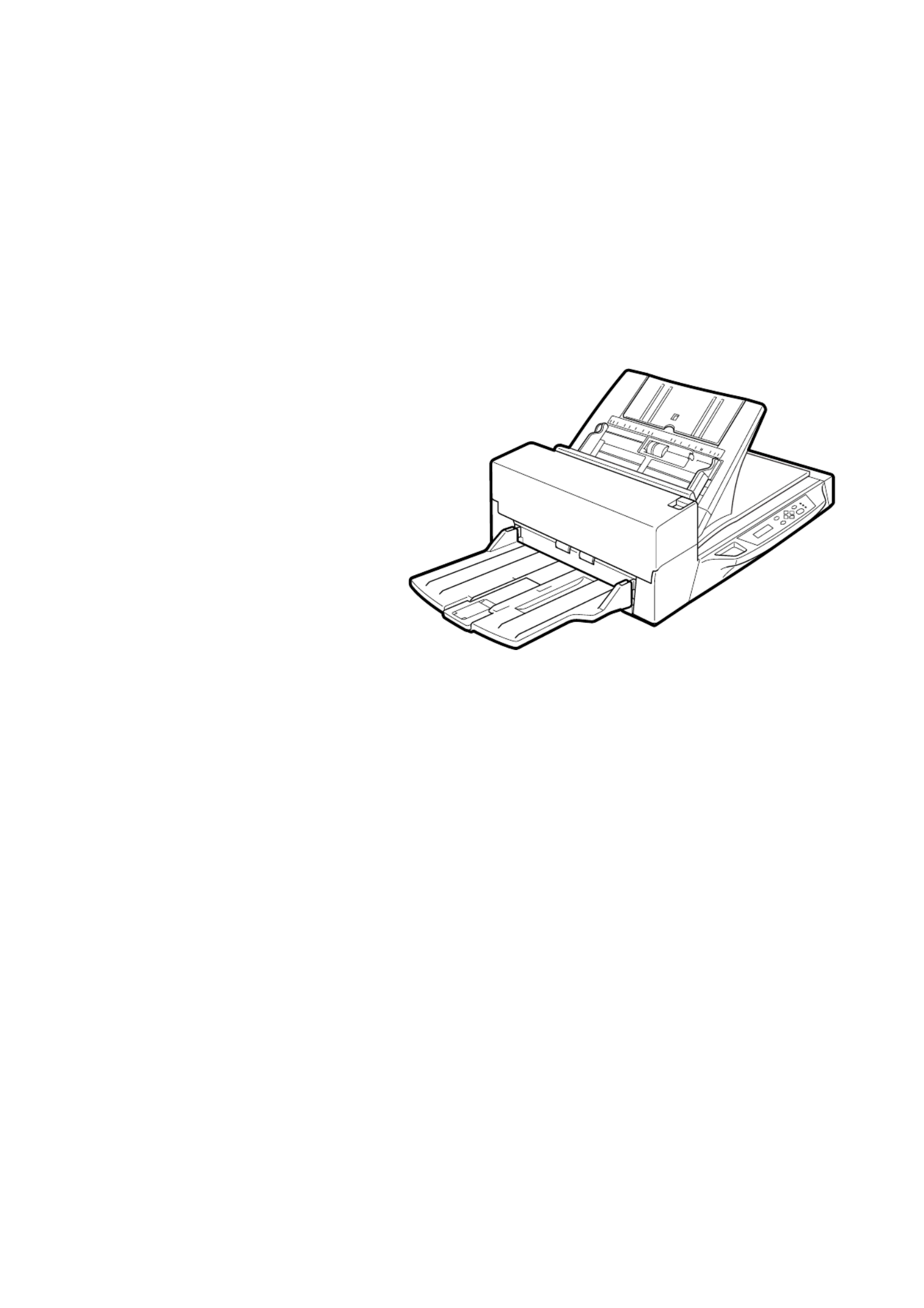
fi-4750L
Document holding pad
7
Document cover
8
ADF paper chute
3
ADF
1
Stacker
6
Power inlet
15
INT connector
11
Power switch
16
Document bed
9
Oparator panel
4
ADF
lever
5
Paper weight
(hidden)
2
IMP connector
10 Third party slot
12
Interface connector
13
EXT connector
14

1-3
NoFunction
Automatically feeds documents to the reading position.
Presses the documents loaded on the ADF paper chute.
Holds the documents to be fed by the ADF.
Displays the status of the scanner. Also displays buttons that enable the
operator to change settings in Feed mode, Manual Feed mode, and Setup
mode.
Opens/closes ADF to enable the removal of jammed documents.
Stacks the read documents.
Presses the document to the Document bed.
Closes over and keeps in place the document to be read.
Holds the document to be read. Also called Flatbed (FB).
Connects to an option.
Connects to the EXT connector.
A Fujitsu Video Interface Option Board is installed.
Connects to the host system with interface cables.
Connects to the INT connector.
Connects to an AC power outlet with the power cable.
Turns the power On or Off.
1
2
3
4
5
6
7
8
9
10
11
12
13
14
15
16

1-4
Stacker
Thumb screw
Guide A
ASY
Pick roller 2
Pick roller 1
Pad ASY
Assemblies
Gate ASY
Chute
roller
Roller
cover
Roller
cover
Chute
roller
Adjustment
stacker

1-5
Operator panel
Exit
Enter
Stop
Previous
Next
Send To/
Start Read
Check
Operator Panel
The operator panel is located on the upper right hand side of the scanner. The panel consists of an
LCD display (16 characters x 2 lines), LEDs and buttons.
Arrangement

1-6
Name of the button and
LED Function
Button Next Displays the next LCD screen.
Previous Displays the previous LCD screen.
Moves the cursor to the left.
Moves the cursor to the right.
Exit When you are entering settings on the Operator panel, pressing this button
returns you immediately to the Scanner Ready screen.
Enter Enters the parameter currently selected by the cursor.
Send To/
Start
Operational only when Manual start mode is set or the Read lamp lights; Starts
the reading when video interface option is used. Some application software
packages make use of this button.
Stop When the Check LED lights, pressing this button releases the error status
(turns off Check and returns to the Scanner Ready screen).
Operational only during the reading operation; stops the reading when the video
interface option is used.
Also turns off the Check lamp.
LED Indicates that the scanner is On.
Read Indicates the scanner is reading or ready to read.
Check If lit, this indicates that an alarm occurred. Pressing the Stop button
turns the Check lamp Off.
If it blinks at one second intervals, this means that a jam or double feed
has been detected. If the problem is jammed paper, removing the jammed
paper turns off the Check lamp. If the problem is double feed, pressing
the Stop button turns off the Check lamp.
If it blinks at four seconds intervals, this means that cleaning the ADF is
necessary.
Button/LED Function

1-8
Operation status
The operation status is indicated by the following messages:
<Power-on>
<Reading>
<Waiting for Start> The scanner displays the following screen when waiting for the
Start button to be pressed:
(Only When the Video Interface
Option is installed.)
<Cleaning request> When the Pick roller cleaning is necessary, the scanner displays
the following on the upper line:
When the ADF glass cleaning is necessary, the scanner displays
the following on the LCD:
Clean the Pick roller or the ADF glass in accordance with the
manual, “Cleaning and Maintenance”.

1-10
Alarm
One of the following messages is displayed if an error occurs in the scanner. If one of the following
error messages is displayed, turn the power Off and then On again. If the same message is displayed,
contact your service representative.
<Optical alarm front>
<Optical alarm back>
<FB mechanism alarm>
NOTICE
When the total number of sheets scanned by the ADF is less than 100, the message above and the
message below are displayed alternately. Remove the bracket (Shipping Lock) that holds the carrier
in place.
<Motor fuse alarm>
<Lamp fuse alarm>

1-11
<Image transfer alarm>
<Memory alarm>
<EEPROM alarm>
<FAN alarm>
<IPC Board alarm>

1-12

CHAPTER
INSTALLATION AND CONNECTIONS
The chapter describes how to install and connect the scanner.
Precautions
Inspection
Repositioning the Shipping Lock
Cable Connections
Mounting the Stacker
Setting the SCSI ID and the SCSI Terminator
2

2-1
Precautions
This section describes precautions to follow when installing the scanner.
To ensure the longevity and proper functioning of your scanner, do not install the scanner in the places
and environments described below.
• Place the scanner away from electrical noise sources, strong magnetic fields, and air flow. If the scanner
is used near an air conditioner, copying machine, or TV set, the scanner may operate incorrectly.
• Keep the scanner out of the sun and away from heaters. These environments may shorten the scanner
life or cause hardware failures.
• Do not install the scanner in a place where vibrations may occur. This environment may cause
hardware failures or may cause the scanner to operate incorrectly.
• Do not install the scanner in humid, dusty, or damp places. These environments may shorten the
scanner life or cause hardware failures.
• Do not place the scanner where liquid spills may occur.
• Be aware of static electricity, which can damage the scanner’s sensitive electronic parts. Be sure the
flooring and the desk are made of materials that do not generate static electricity.
For information on the minimum required size of the installation space, see Chapter 5, “Specifications”.

2-3
Repositioning the Shipping Lock
To keep the scanner from being damaged during shipping, the carrier unit is fixed with a Shipping Lock.
After placing the carrier unit where it will be installed, change the position of this Shipping Lock as
explained below.
1Place the image scanner on the edge of the desktop so that the left side of the scanner (where the
ADF is attached) extends from the desktop. Do not set the image scanner upside down or on its
side.
CAUTION
Do not let the scanner hang more than 20 cm (8 in.) over the edge of the desk.
2Remove the shipping lock from position A. Then, install the shipping lock at position
B
.
CAUTION
Before moving or storing the scanner, make sure that the shipping lock is set to the
shipment position to prevent possible damage. Before setting the shipping lock, make sure
that the carrier has been returned to the home position.
B
A
Good
Bad Bad
less than 20 cm
(8 in.)
Front side
Front side
Enlarged
Shipping Lock
(Position for operation)
Shipping Lock
(Position for shipment)
ADF side
Bottom view
Shipping Lock
(Position for storage,
position for shipment)
Enlarged section A

2-4
Cable Connections
This section describes how to connect the cables.
Connect the cables as follows:
Turning the power switch Off
Press the side of the power switch to turn the power Off.“ ”O
Connecting the power cable
Connect the power cable to the power inlet of the device and a power outlet.
Power inlet Power cable
for North America
for Europe
Power outlet
Power OFF
Power ON
Power switch

2-5
Connecting the interface cables
Connect the SCSI interface cables and secure them.
NOTICES
1. Factory default for the SCSI terminator is On. If the scanner is in the middle of the daisy chain or of two
devices, turn the scanner termination Off via the operator panel.
2. The factory default for the SCSI ID is 5. If the ID of the scanner is the same as the other device,
change the ID via the operator panel or change the ID of the other device.
Connecting the chute cable
Connect the chute cable.
Back of the image scanner
Interface
cables
To the host system
Chute cable
To EXT (10-pin)
EXT (8-pin)
2-6
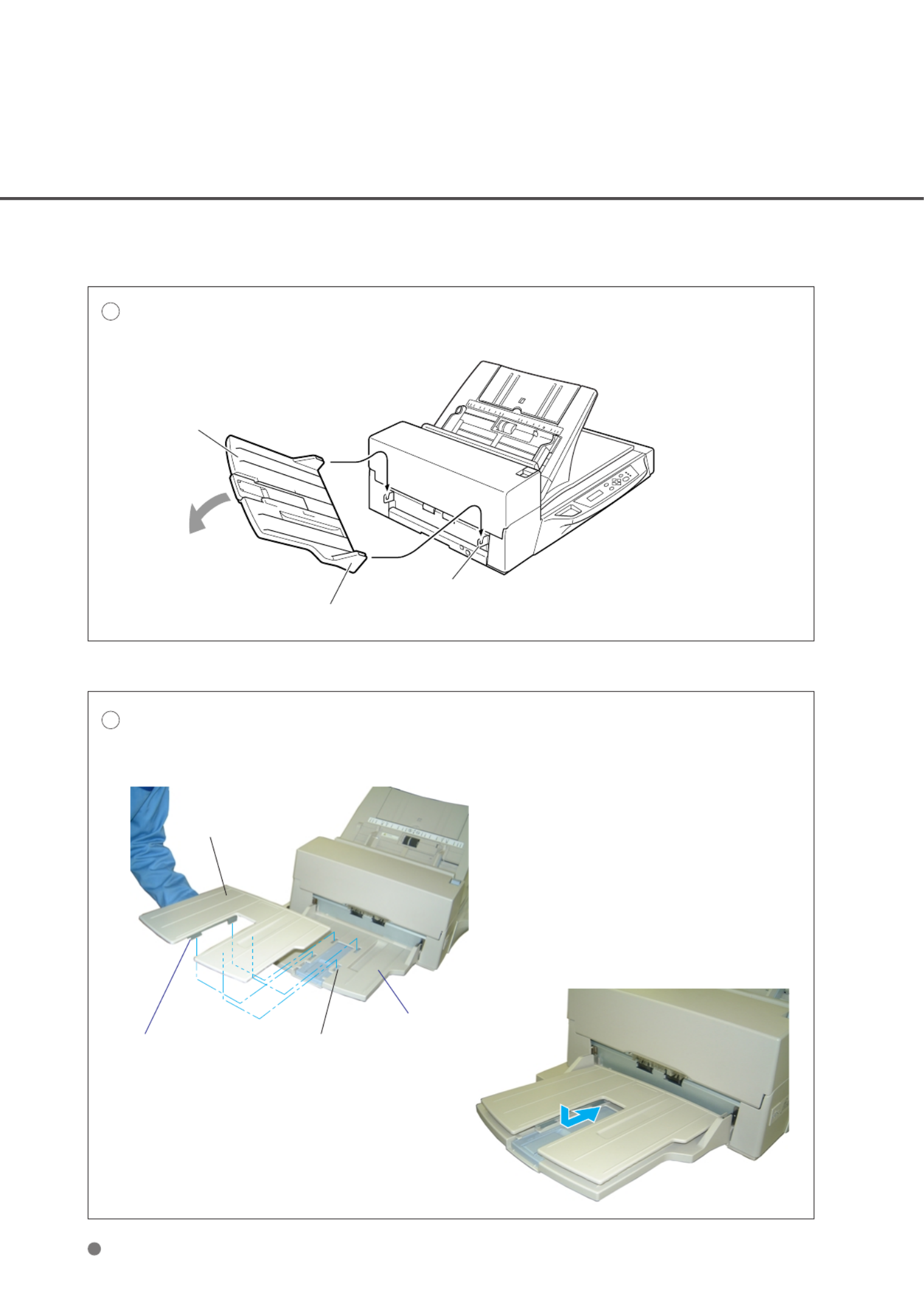
Mounting the Stacker
Mount the stacker using the following procedure.
1Mount the stacker.
Hook the pins on the stacker to the claws on the image scanner.
Stacker
Pin (inside)
Claw
2
Mount the adjustment stacker.
Insert the four claws of the adjustment stacker into the four holes on the stacker, and push the
adjustment stacker towards the scanner.
Adjustment
stacker
Four claws
(Two are hidden)
Four holes
Stacker

2-7
Setting the SCSI ID and the SCSI Terminator
The default of the SCSI ID is 5. The SCSI ID is set by using the Setup mode of the operator panel. The
procedure to change the SCSI ID is as follows:
1Turn the power On by
pressing the side of the“ ”I
power switch. The scanner
displays “ ”Scanner Ready
on the lower line of the LCD.
2Press the “ ”Next button.
The scanner displays “Mode
select 1”.
NOTICE
If the scanner have a video interface option, the scanner displays Mode Select 0 on the LCD.“ ”
3Press the “ ”Next button
again. The scanner displays
“ ”Mode select 2 meaning
that the setup mode is
ready.
4Press the “ ”Enter button.
The scanner displays the
following:
5Press the “ ”Next button
ten. The scanner displays
“ ”SCSI ID on the upper line
of the LCD.
6Select the desired SCSI ID by pressing the “ ”or “ ” “ buttons, and then pressing Enter” (the SCSI
ID is set.)
7Press “ ” “ ” ’Exit to return to the Scanner Ready screen if you don t need to change the terminator.
NOTICE
If no other device is using the same SCSI ID, the scanner ID does not have to be changed.
NOTICE
The new ID does not take effect until the system power is turned On again.

2-8
8Press “ ”Next , the scanner
displays “ ”Terminator on the
upper line of the LCD.
Select On Off“ ” or “ ” by pressing or , then pressing “Enter”.
NOTICE
The scanner includes an internal SCSI terminator that can be turned On and Off from the operator panel of
the scanner. The factory default is “ ”On.
9Press “ ” “ ”Exit to return to the Scanner Ready state.
Product specificaties
| Merk: | Fujitsu |
| Categorie: | Scanner |
| Model: | fi-4750L |
Heb je hulp nodig?
Als je hulp nodig hebt met Fujitsu fi-4750L stel dan hieronder een vraag en andere gebruikers zullen je antwoorden
Handleiding Scanner Fujitsu

16 Juni 2023
11 Mei 2023
9 Mei 2023
8 Mei 2023
3 Mei 2023
18 April 2023
13 April 2023
7 April 2023
4 April 2023
26 Maart 2023
Handleiding Scanner
- Scanner Braun
- Scanner HP
- Scanner Panasonic
- Scanner Nikon
- Scanner Epson
- Scanner Canon
- Scanner Honeywell
- Scanner Medion
- Scanner Xerox
- Scanner Agfa
- Scanner Agfaphoto
- Scanner Albrecht
- Scanner Antec
- Scanner Avision
- Scanner Brother
- Scanner Dnt
- Scanner Dyka
- Scanner Dymo
- Scanner Easypix
- Scanner Elmo
- Scanner Genius
- Scanner GlobalTronics
- Scanner Hella
- Scanner ICarsoft
- Scanner Ion
- Scanner Ipevo
- Scanner IRIS
- Scanner Kenko
- Scanner Kensington
- Scanner Kodak
- Scanner Kogan
- Scanner Konica Minolta
- Scanner Konig
- Scanner Lenco
- Scanner Lexmark
- Scanner Maginon
- Scanner Martin
- Scanner Minolta
- Scanner Mustek
- Scanner Nedis
- Scanner Plustek
- Scanner RadioShack
- Scanner Reflecta
- Scanner Renkforce
- Scanner Ricoh
- Scanner Rittz
- Scanner Rollei
- Scanner Sagem
- Scanner Silvercrest
- Scanner Targus
- Scanner Technaxx
- Scanner Tevion
- Scanner Traveler
- Scanner Trust
- Scanner Uniden
- Scanner Veho
- Scanner Voltcraft
- Scanner Yupiteru
- Scanner Zebra
- Scanner Zolid
- Scanner Jay-tech
- Scanner Jobo
- Scanner Matter And Form
- Scanner Steren
- Scanner Cobra
- Scanner DTRONIC
- Scanner Eurolite
- Scanner Visioneer
- Scanner AVerMedia
- Scanner Blackmagic Design
- Scanner Newland
- Scanner Panduit
- Scanner Vupoint Solutions
- Scanner Ross-Tech
- Scanner DENSO
- Scanner Perfect Choice
- Scanner Soundsation
- Scanner CDVI
- Scanner Scan Dimension
- Scanner Pacific Image
- Scanner Doxie
- Scanner CZUR
- Scanner Cartrend
- Scanner 3DMAKERPRO
- Scanner Neat
- Scanner Ambir
- Scanner Creality
- Scanner Microtek
Nieuwste handleidingen voor Scanner

29 Maart 2025

19 Februari 2025
28 Januari 2025
16 Januari 2025
14 December 2024
14 December 2024
5 December 2024

2 December 2024
2 December 2024

1 December 2024