Extron TLP 1000TV Handleiding
Extron
Afstandsbediening
TLP 1000TV
Lees hieronder de 📖 handleiding in het Nederlandse voor Extron TLP 1000TV (4 pagina's) in de categorie Afstandsbediening. Deze handleiding was nuttig voor 73 personen en werd door 2 gebruikers gemiddeld met 4.5 sterren beoordeeld
Pagina 1/4
1
Product Category
IMPORTANT:
Refer to www.extron.com for
the complete TLP 1000 Series
user guide before connecting
the product to the power source.
TLP 1000MV and TLP 1000TV • Setup Guide
Overview
The Extron TLP 1000MV (wall-mounted) and TLP 1000TV (desk-mounted) TouchLink™ Panels provide simple and versatile
configuration and control for a range of IP Link® control systems. Graphic and text objects are displayed on the screen.
These objects have system control functions associated with them and the touch overlay allows you to activate or regulate
those functions.
These touchpanels communicate through an Ethernet connection to a configurable IP Link control processor. Video and
audio input is provided by a twisted pair cable connected to an MTP transmitter.
NOTE: The network output must be connected to a network switch, hub, or router that is connected to an Ethernet
LAN or the Internet. An Extron IP Link controller must also be connected to the same network. Suggested
models include IPL T S series (for example, IPL T S4), IPL 250, IPL T CR48, IPL T SFI244, or IPCP 505.
Extron strongly recommends that power is provided by a Power over Ethernet (PoE) power supply.
This guide provides basic instructions for experienced installers to mount and perform initial configuration on the
TLP 1000 series of touchpanels. Full instructions and reference material can be found in the TLP 1000MV and TLP 1000TV
User Guide, which is available on the Extron website (www.extron.com).
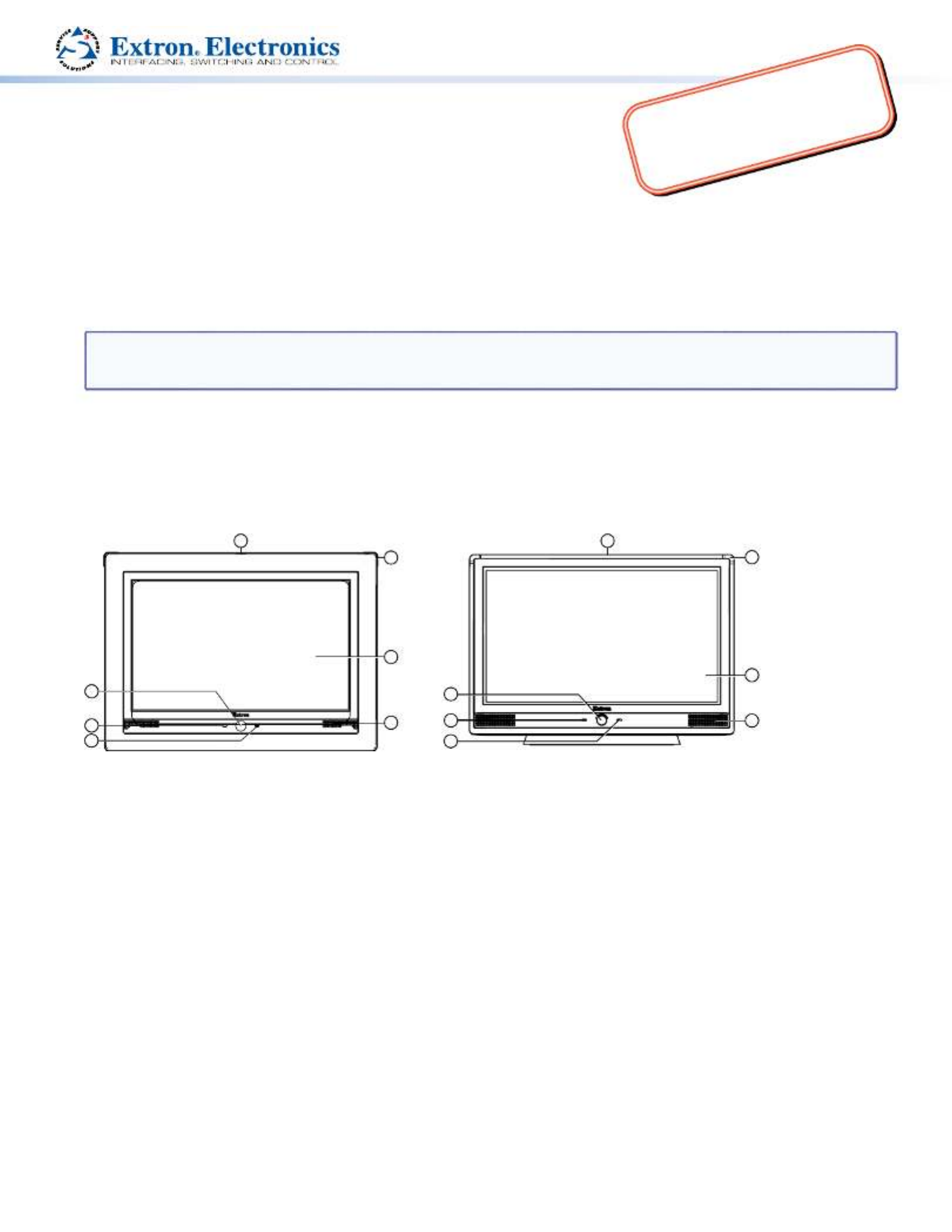
Front Panel Features
5
6
1
2
3
4
1
2
3
5
6
4
77
Extron TLP 1000MV Extron TLP 1000TV
a when no motion has been detected for a user-defined period of time, the unit goes into sleep Motion Sensor —
mode. When motion is detected by the sensor, the screen display is restored and active.
b is located below the LCD screen.Microphone —
c — is unlit during normal operation. The LED blinks red if the connection to the IP Link Connection status LED
controller is lost.
d one on each top corner can be programmed to provide system feedback. They light red or Programmable LEDs —
green and can blink or light solid.
e has a 1024x600 resolution with a touch overlay. Extron software is used to design and configure a LCD screen —
graphic user interface to display buttons, text, or icons, which have user-defined functions associated with them.
f Two speakers placed under the screen, on either side of the panel, provide audible feedback for the user.Speakers —
g (can only be seen from above the unit) monitors ambient light level and adjusts screen brightness.Light Sensor —

2
Product Category
810
9
Extron TLP 1000MV
Use the Extron pry tool to remove the front faceplate of the
TLP 1000MV:
h activates the for calibrating Menu button — on-screen menus
the unit (see page 3).
i allows the unit to be reset in any of four Reset button —
different modes (see “ ” on page 4).
Reset Modes
j provides feedback about the reset status when the Reset LED —
user presses the reset button (see “ ” on page 4).
Reset Modes
TLP 1000MV Reset Buttons and LED
Rear Panel Features
Extron TLP 1000MV Extron TLP 1000TV
8
14
9
10
15
11
12
13
14
11
12
13
h (Menu button), i (Reset button), and j (Reset LED) — see “TLP 1000MV Reset Buttons and LED“ above.
k Three MTP signal adjustments are available for S-video luminance gain (VID/Y), S-video MTP Signal Adjustments —
chrominance gain (C), and sharpness (S). For composite video signals, the gain is controlled by the VID/Y adjustment.
l A twisted pair cable, terminated with an RJ-45 connector, provides video and audio input MTP Input (optional) —
from an Extron MTP transmitter. For the TLP 1000TV, the MTP port is in the top surface of the recessed area, indicated
by the red arrow.
CAUTION: Ensure the MTP cable is connected to the MTP input and the network cable is connected to the
Network input. The voltages carried by the cables is different and connecting the MTP cable to the
Network input will damage the touchpanel unit.
m A twisted pair cable, terminated Network and Power over Ethernet Connector —
with an RJ-45 connector, provides network connection. For the TLP 1000TV, the LAN
port is in the top surface of the recessed area, indicated by the blue arrow.
Extron recommends using the Power over Ethernet (PoE) power supply (provided).
Use straight-through cables to connect the LAN-IN port to a network switch and the
PWR LAN-OUT port to the LAN port of the touchpanel (see the figure to the right).
Connect the IEC power cord to a convenient 100 VAC to 240 VAC, 50-60 Hz power
source.
An Extron IP Link control interface must also be connected to the same network
domain as the TouchLink Panel. See the note on page 1 for a list of suggested models.
CAUTION: Do not connect any power supply before reading the Cautions about power supplies in the “Panel
Features” section of the .TLP 1000MV and TLP 1000TV User Guide
n Extron recommends using the PoE power supply (provided). As an alternative, Power connector (optional) —
you may choose to connect the two pole, 3.5 mm captive screw connector from the 12 VDC, 1.0 A power supply (not
provided) to the power supply socket on the rear panel.
o For use with the Extron LPVM-1 (part number ). For VESA mounting holes (TLP 1000TV only) — 60-1099-02
complete mounting options of both the TLP 1000MV and TLP 1000TV, see the .TLP 1000MV and TLP 1000TV User Guide
PWR LAN-OUT LAN-IN
To Networ
k Switch
To TLP 1000
Power er Ethernet (PoE) wer Supplyov Po

3
Product Category
Initial Conguration
Before use, configure the touchpanel, using the on-screen menus.
1. Press the Menu button once. (See “ “ TLP 1000MV Reset Buttons and LED
for the TLP 1000MV or “ “ for the TLP 1000TV.) The Rear Panel Features
Main menu screen opens (see figure at right).
2. Touch an on-screen button to highlight and select that option (the button
turns green with a yellow border).
3. Use the and buttons to adjust the value. Some options have a
single button and toggle between and when the button is pressed.
There are five different screens ( , , , , and ) that
can be selected by pressing the appropriate button at the left side of the screen. There is also an button at the bottom
left corner of the screen for leaving the menus.
Use the screens to adjust the following options (for more information, see the ).TLP 1000MV and TLP 1000TV User Guide
Main — Adjusts the Sleep timer, Backlight, Auto Backlight, and Wake on Motion functions. The screen also provides
information about the PoE status.
Volume — Adjusts the Master, Click, Sounds, and Line In volume settings.
Time — Sets the correct time and date.
Network — Sets the IP address and the subnet mask, and enables or disables Dynamic Host Configuration Protocol.
Video — Provides a small video preview window and the controls to adjust the video contrast, color, brightness, and tint.
Calibration Menu
1. Press the Menu button a second time to open the calibration-screen. (See
“ “ for the TLP 1000MV or “TLP 1000MV Reset Buttons and LED Rear Panel
Features“ for the TLP 1000TV.) The on-screen button in the top left corner
is highlighted.
2. Press the highlighted button until it turns gray and a new button is
highlighted. When all four points have been calibrated, the screen reopens
to the Main Screen.
3. Press to close the on-screen menus.
4. If necessary (for the TLP 1000MV), reattach the faceplate.
Mounting Options
TLP 1000MV
zWall-mounting — using the Extron BB 1000M back box (part number ) or the Extron EWB 1000 wall box 70-887-01
(part number ), either of which must be purchased separately. Follow the instructions provided with the kit. 70-950-02
The unit may also be mounted directly to the wall without a kit, as described on page 4.
zFurniture-mounting — as described on page 4.
zRack-mounting — using the RM 1000M kit (part number ), which must be purchased separately. Follow the 70-886-01
instructions in the user guide provided with the kit.
TLP 1000TV
zDesktop-mounting — by standing the unit on a suitable surface. For added security, the unit may be attached to the
desktop, using two screws, as described in the .TLP 1000MV and TLP 1000TV User Guide
The TLP 1000TV can also be mounted using the Extron SMA-1 Swivel-Mount Adapter (part number ), which 70-747-01
must be purchased separately. Follow the instructions provided with the kit and the TLP 1000MV and TLP 1000TV User
Guide.
zVESA-mounting — using the D-type (75 x 75 mm) mounting pattern. The Extron LPVM-1 kit (part number 60-1099-02)
is optional and must be purchased separately. Follow the instructions provided with the kit. To VESA-mount the TLP
1000TV, the base must be removed from the unit, as described in the .TLP 1000MV and TLP 1000TV User Guide
Main
Volume
Time
Network
Video
Exit
On
On
Down Up
Sleep timer: 300 Sec
Down Up
Backlight: 073%
Auto Backlight
Wake on Motion
PoE
Active
++
++
Press and Hold
Highlighted Box
Until Color Changes
Product specificaties
| Merk: | Extron |
| Categorie: | Afstandsbediening |
| Model: | TLP 1000TV |
| Kleur van het product: | Zwart |
| Ingebouwd display: | Ja |
| Gewicht: | 2400 g |
| Breedte: | 254 mm |
| Diepte: | 186 mm |
| Hoogte: | 182 mm |
| Gewicht verpakking: | 4000 g |
| Beeldscherm: | TFT |
| Beeldschermdiagonaal: | 10.1 " |
| Resolutie: | 1024 x 600 Pixels |
| Afmetingen verpakking (BxDxH): | 289 x 311 x 267 mm |
| Certificering: | CE, c-UL, UL\nCE, C-tick, FCC Class A, ICES, KCC, VCCI |
| Interface: | Bedraad |
| Temperatuur bij opslag: | -20 - 60 °C |
| Maximumbereik: | - m |
| Luchtvochtigheid bij opslag: | 10 - 90 procent |
| Bedrijfstemperatuur, bereik: | 32 - 122 °F |
| Input type: | Aanraakscherm |
| juiste gebruik afstandsbediening: | DVD/Blu-ray, PC, TV, VCR |
| Bedrijfstemperatuur (T-T): | 0 - 50 °C |
| Relatieve vochtigheid in bedrijf (V-V): | 10 - 90 procent |
| Display met achtergrondverlichting: | Ja |
| Temperatuurbereik voor opslag (T-T): | -4 - 140 °F |
Heb je hulp nodig?
Als je hulp nodig hebt met Extron TLP 1000TV stel dan hieronder een vraag en andere gebruikers zullen je antwoorden
Handleiding Afstandsbediening Extron

15 Augustus 2024
15 Augustus 2024
14 Augustus 2024
14 Augustus 2024
14 Augustus 2024
14 Augustus 2024
14 Augustus 2024
Handleiding Afstandsbediening
- Afstandsbediening Philips
- Afstandsbediening IKEA
- Afstandsbediening Sony
- Afstandsbediening Samsung
- Afstandsbediening Xiaomi
- Afstandsbediening Panasonic
- Afstandsbediening Nikon
- Afstandsbediening LG
- Afstandsbediening AEG
- Afstandsbediening Canon
- Afstandsbediening Garmin
- Afstandsbediening Grundig
- Afstandsbediening Honeywell
- Afstandsbediening JVC
- Afstandsbediening Kenwood
- Afstandsbediening Miele
- Afstandsbediening Motorola
- Afstandsbediening Medion
- Afstandsbediening Onkyo
- Afstandsbediening Pioneer
- Afstandsbediening Toshiba
- Afstandsbediening UPC
- Afstandsbediening Yamaha
- Afstandsbediening A.C.Ryan
- Afstandsbediening Absima
- Afstandsbediening Abus
- Afstandsbediening Alpine
- Afstandsbediening Amazon
- Afstandsbediening Amewi
- Afstandsbediening Ansmann
- Afstandsbediening Antec
- Afstandsbediening Apart
- Afstandsbediening Apple
- Afstandsbediening Arcam
- Afstandsbediening Archos
- Afstandsbediening Artsound
- Afstandsbediening AT-T
- Afstandsbediening Audio-Technica
- Afstandsbediening Audiovox
- Afstandsbediening Autel
- Afstandsbediening Axis
- Afstandsbediening Bang Olufsen
- Afstandsbediening BeamZ
- Afstandsbediening Benning
- Afstandsbediening Beoplay
- Afstandsbediening Blaupunkt
- Afstandsbediening Bose
- Afstandsbediening Brennenstuhl
- Afstandsbediening Danfoss
- Afstandsbediening Delta
- Afstandsbediening Devolo
- Afstandsbediening DJI
- Afstandsbediening Doro
- Afstandsbediening Dual
- Afstandsbediening Ebode
- Afstandsbediening Edision
- Afstandsbediening ELV
- Afstandsbediening Eminent
- Afstandsbediening Emtec
- Afstandsbediening Energy Sistem
- Afstandsbediening Entone
- Afstandsbediening EQ-3
- Afstandsbediening ESYLUX
- Afstandsbediening Eurosky
- Afstandsbediening Exxter
- Afstandsbediening Ezviz
- Afstandsbediening Ferguson
- Afstandsbediening FireAngel
- Afstandsbediening Funai
- Afstandsbediening Furman
- Afstandsbediening Fusion
- Afstandsbediening Futaba
- Afstandsbediening Gaggenau
- Afstandsbediening Geemarc
- Afstandsbediening Genius
- Afstandsbediening Glashart Media
- Afstandsbediening Grohe
- Afstandsbediening Hager
- Afstandsbediening Hama
- Afstandsbediening Hannspree
- Afstandsbediening Harman Kardon
- Afstandsbediening Hartig Helling
- Afstandsbediening Hema
- Afstandsbediening Hikvision
- Afstandsbediening HQ
- Afstandsbediening Humax
- Afstandsbediening Hunter
- Afstandsbediening Iiyama
- Afstandsbediening Infinity
- Afstandsbediening Insignia
- Afstandsbediening Intermatic
- Afstandsbediening Kathrein
- Afstandsbediening Kensington
- Afstandsbediening Kicker
- Afstandsbediening KlikaanKlikuit
- Afstandsbediening Konig
- Afstandsbediening KPN
- Afstandsbediening Lifetec
- Afstandsbediening Loewe
- Afstandsbediening Logic3
- Afstandsbediening Logilink
- Afstandsbediening Logitech
- Afstandsbediening Maginon
- Afstandsbediening Magnum
- Afstandsbediening Marantz
- Afstandsbediening Marmitek
- Afstandsbediening Maximex
- Afstandsbediening MB Quart
- Afstandsbediening Medion MD6461
- Afstandsbediening Meliconi
- Afstandsbediening Metronic
- Afstandsbediening Milwaukee
- Afstandsbediening Mitsubishi
- Afstandsbediening Monacor
- Afstandsbediening Multibox
- Afstandsbediening Multiplex
- Afstandsbediening NAD
- Afstandsbediening Naim
- Afstandsbediening Nec
- Afstandsbediening Nedis
- Afstandsbediening Neewer
- Afstandsbediening Nemef
- Afstandsbediening Niko
- Afstandsbediening Packard Bell
- Afstandsbediening Parkside
- Afstandsbediening Parrot
- Afstandsbediening Perel
- Afstandsbediening Pixel
- Afstandsbediening Prolectrix
- Afstandsbediening Provision
- Afstandsbediening Provision ISR
- Afstandsbediening Q-Sonic
- Afstandsbediening Rademacher
- Afstandsbediening RadioShack
- Afstandsbediening Ranex
- Afstandsbediening RCA
- Afstandsbediening Reely
- Afstandsbediening Reflecta
- Afstandsbediening Remotec
- Afstandsbediening Revo
- Afstandsbediening Revox
- Afstandsbediening Rockford Fosgate
- Afstandsbediening Rotel
- Afstandsbediening Ruwido
- Afstandsbediening Samlex
- Afstandsbediening Schaudt
- Afstandsbediening Silvercrest
- Afstandsbediening Sitecom
- Afstandsbediening Skymaster
- Afstandsbediening Smart
- Afstandsbediening Smartwares
- Afstandsbediening Sonos
- Afstandsbediening Spektrum
- Afstandsbediening Steinel
- Afstandsbediening Strong
- Afstandsbediening Sunwave
- Afstandsbediening Sweex
- Afstandsbediening Tado
- Afstandsbediening Targus
- Afstandsbediening Tascam
- Afstandsbediening TCM
- Afstandsbediening Technaxx
- Afstandsbediening Technics
- Afstandsbediening Technika
- Afstandsbediening Technisat
- Afstandsbediening Telefunken
- Afstandsbediening Tevion
- Afstandsbediening Tevion (Medion)
- Afstandsbediening Thomson
- Afstandsbediening Tihao
- Afstandsbediening Toa
- Afstandsbediening TomTom
- Afstandsbediening Trust
- Afstandsbediening TV Vlaanderen
- Afstandsbediening Uni-T
- Afstandsbediening Unitron
- Afstandsbediening Universal Electronics
- Afstandsbediening Universal Remote Control
- Afstandsbediening VDO Dayton
- Afstandsbediening Velleman
- Afstandsbediening Verizon
- Afstandsbediening Viper
- Afstandsbediening Vivanco
- Afstandsbediening Vizio
- Afstandsbediening Vogels
- Afstandsbediening Voxx
- Afstandsbediening Wacom
- Afstandsbediening Waeco
- Afstandsbediening Walkera
- Afstandsbediening Watson
- Afstandsbediening Xavax
- Afstandsbediening Yale
- Afstandsbediening Zalman
- Afstandsbediening Zapman
- Afstandsbediening Ziggo
- Afstandsbediening Jasco
- Afstandsbediening JBSystems
- Afstandsbediening Jensen
- Afstandsbediening JL Audio
- Afstandsbediening Jolly
- Afstandsbediening Jung
- Afstandsbediening OEM
- Afstandsbediening Olympia
- Afstandsbediening Omega
- Afstandsbediening One For All
- Afstandsbediening Online
- Afstandsbediening Optex
- Afstandsbediening Clas Ohlson
- Afstandsbediening Continental Edison
- Afstandsbediening Bang And Olufsen
- Afstandsbediening CSL
- Afstandsbediening Exibel
- Afstandsbediening Schwaiger
- Afstandsbediening Steren
- Afstandsbediening T'nB
- Afstandsbediening Clarion
- Afstandsbediening Conrad
- Afstandsbediening Televés
- Afstandsbediening Conceptronic
- Afstandsbediening Cotech
- Afstandsbediening Aplic
- Afstandsbediening Ardes
- Afstandsbediening SilverStone
- Afstandsbediening Vakoss
- Afstandsbediening AXIL
- Afstandsbediening Elbe
- Afstandsbediening Majestic
- Afstandsbediening Malmbergs
- Afstandsbediening Msonic
- Afstandsbediening Natec
- Afstandsbediening Satechi
- Afstandsbediening Savio
- Afstandsbediening SIIG
- Afstandsbediening DSC
- Afstandsbediening REV
- Afstandsbediening Zephir
- Afstandsbediening Scosche
- Afstandsbediening Tripp Lite
- Afstandsbediening American DJ
- Afstandsbediening Chauvet
- Afstandsbediening Nexa
- Afstandsbediening Cisco
- Afstandsbediening Pro-Ject
- Afstandsbediening Vello
- Afstandsbediening Delta Dore
- Afstandsbediening Fantini Cosmi
- Afstandsbediening Vision
- Afstandsbediening Asustor
- Afstandsbediening Gefen
- Afstandsbediening Ei Electronics
- Afstandsbediening Electia
- Afstandsbediening Fibaro
- Afstandsbediening Innr
- Afstandsbediening Chief
- Afstandsbediening Chamberlain
- Afstandsbediening Magnus
- Afstandsbediening Manfrotto
- Afstandsbediening CGV
- Afstandsbediening CME
- Afstandsbediening Heitech
- Afstandsbediening SMK-Link
- Afstandsbediening Swiss Sense
- Afstandsbediening Tiq
- Afstandsbediening Interphone
- Afstandsbediening Lindy
- Afstandsbediening IOGEAR
- Afstandsbediening Xit
- Afstandsbediening Hähnel
- Afstandsbediening DataVideo
- Afstandsbediening Vaddio
- Afstandsbediening Bigben Interactive
- Afstandsbediening Adj
- Afstandsbediening AV:link
- Afstandsbediening Neumann
- Afstandsbediening Valueline
- Afstandsbediening Busch-Jaeger
- Afstandsbediening EVE
- Afstandsbediening Projecta
- Afstandsbediening Genaray
- Afstandsbediening Nanlite
- Afstandsbediening Profoto
- Afstandsbediening Metra
- Afstandsbediening Russound
- Afstandsbediening Engel Axil
- Afstandsbediening Hegel
- Afstandsbediening RGBlink
- Afstandsbediening Bazooka
- Afstandsbediening Wentronic
- Afstandsbediening EQ3
- Afstandsbediening Homematic IP
- Afstandsbediening Neets
- Afstandsbediening AMX
- Afstandsbediening Arctic Cooling
- Afstandsbediening Crestron
- Afstandsbediening ORNO
- Afstandsbediening ETiger
- Afstandsbediening Aeon Labs
- Afstandsbediening AudioControl
- Afstandsbediening Aputure
- Afstandsbediening Fortin
- Afstandsbediening Simplify
- Afstandsbediening Wet Sounds
- Afstandsbediening SVS
- Afstandsbediening ProMaster
- Afstandsbediening Match
- Afstandsbediening Libec
- Afstandsbediening Vimar
- Afstandsbediening Morel
- Afstandsbediening Antelope Audio
- Afstandsbediening H-Tronic
- Afstandsbediening PDP
- Afstandsbediening Intertechno
- Afstandsbediening Ecler
- Afstandsbediening PeakTech
- Afstandsbediening Elite Screens
- Afstandsbediening Roswell
- Afstandsbediening SpeakerCraft
- Afstandsbediening Syrp
- Afstandsbediening Bravo
- Afstandsbediening Pentatech
- Afstandsbediening PowerBass
- Afstandsbediening TELE System
- Afstandsbediening Multibrackets
- Afstandsbediening Audiofrog
- Afstandsbediening Memphis Audio
- Afstandsbediening Nanoleaf
- Afstandsbediening GBS Elettronica
- Afstandsbediening Sonoff
- Afstandsbediening Gewiss
- Afstandsbediening Insteon
- Afstandsbediening Mosconi
- Afstandsbediening Lutron
- Afstandsbediening C2G
- Afstandsbediening Control4
- Afstandsbediening MIOPS
- Afstandsbediening Compustar
- Afstandsbediening Ridem
- Afstandsbediening Canal Digitaal
- Afstandsbediening URC
Nieuwste handleidingen voor Afstandsbediening
26 Maart 2025
26 Maart 2025

13 Maart 2025
25 Januari 2025
10 Maart 2025

9 Maart 2025
9 Maart 2025
25 Februari 2025
19 Februari 2025
25 Januari 2025