Extron PowerCage FOX Tx DVI Plus Handleiding
Extron
AV extender
PowerCage FOX Tx DVI Plus
Lees hieronder de 📖 handleiding in het Nederlandse voor Extron PowerCage FOX Tx DVI Plus (2 pagina's) in de categorie AV extender. Deze handleiding was nuttig voor 27 personen en werd door 2 gebruikers gemiddeld met 4.5 sterren beoordeeld
Pagina 1/2

This guide provides instructions for an experienced installer to set up and operate an Extron ®
PowerCage™ FOX Tx/Rx DVI Plus ber optic video and audio extenders (transmitter and receiver).
NOTES: The ber optic output signal from a PowerCage FOX Tx DVI Plus transmitter
•
can be received by a PowerCage FOX or FOXBOX DVI Plus receiver.only
• The PowerCage FOX DVI Plus receiver can accept signals from any
PowerCage FOX, FOXBOX, or FOX 500 transmitter, including VGA models.
Installation
Step 1 — Mounting
Install the Tx, Rx, or both in PowerCage enclosures as required.
NOTES: • PowerCage boards are hot-swappable.
• Ensure the boards are ush with the rear of the
enclosure and the screws securely tightened
with a screwdriver before applying power.
Step 2 — Input and Output Connections
a. Connect a DVI video source to the Input connector on the
transmitter and a DVI display to the Output connector on the
receiver.
b. Connect a balanced or unbalanced, stereo or mono audio input to
the transmitter via the Audio Input captive screw connector and
a balanced or unbalanced stereo or mono audio device to the receiver via
the Audio Output captive screw connector. See the drawing below.
Unbalanced Stereo Output Balanced Stereo Output
L R
Ring
Sleeve(s)
Tip
Tip
Ring
L R
Sleeve(s)
L R
L R
Tip
Tip
NO GROUND HERE.
NO GROUND HERE.
Unbalanced Stereo Input Balanced Stereo Input
Ring
Slee (s)ve
Tip
Sleeve
Tip
Sleeve
Tip
Tip
Ring
Do not tin the wires!
CAUTION: For unbalanced audio, connect the sleeves to the ground contact. connect the sleeves to the negative (-) DO NOT
contacts).
c. If you want the PowerCage FOX units to pass serial data or control signals, such as for serial control of a
RS-232
O
VER FIBER
Tx Rx
projector, connect the primary device to the transmitter and the secondary device to the receiver via the rst three poles
of the RS-232 Over Fiber captive screw connectors on units.both
NOTE: For RS-232 responses (from the receiver to the transmitter), you must install the cable in step and leave the receiver in 2c
normal conguration.
d. For serial control of the transmitter and receiver, connect a host device, such as a computer, to the Remote RS-232
1 2
REMOTE
RS-232
Tx Rx
ALARM
port on unit via three poles (Tx, Rx, and either _) of the Remote RS-232/Alarm 5-pole captive screw connector on either
unit. The protocol for these ports is as follows:
• 9600 baud • no parity • 8 data bits
• 1 stop bit • no ow control
Refer to the for detailed information about using the Simple Instruction Set (SIS™) commands and PowerCage FOX Tx/Rx User Guide
the Windows®-based FOX Extender program to set up and operate the transmitter and receiver and to take advantage of the various
adjustments and test patterns available on the PowerCage FOX units.
e. For remote monitoring of the status of the Rx optical link on either the transmitter or receiver, connect a locally
1 2
REMOTE
RS-232
Tx Rx
ALARM
constructed or obtained device to the two Alarm poles of the Remote RS-232/Alarm 5-pole captive screw connector on
that unit. The two poles are shorted together when no light is detected. The shorted pins complete a circuit, allowing the
monitoring device to sense the alarm.
M
AU T
1 2P GAIN
C
INPUT
Pow er
MTP R A
Tx Rx
HD/SDI OUTPUTS
Po we rC age
FOX 3G HD-SDI
1 2x Rx
Tx
LARM
Rx
Po we rC age
FOX Rx AV
5A MAX.
100-2 40V 50/60 Hz
1 2
REM EOTRS-232
RS-232OVER FIBER
Tx Rx
Tx
ALARM
RxOUTPUT
RGB
Po we rC age
FOX T X DVI Plus
Tx Rx
L RAUDIO
16 slots fit either:
16 single slot boards,
8 double slot boards,
or a mix of board sizes.
Power
Supply
Scre
ws
DVI
1
PowerCage FOX Tx/Rx DVI Plus Setup Guide
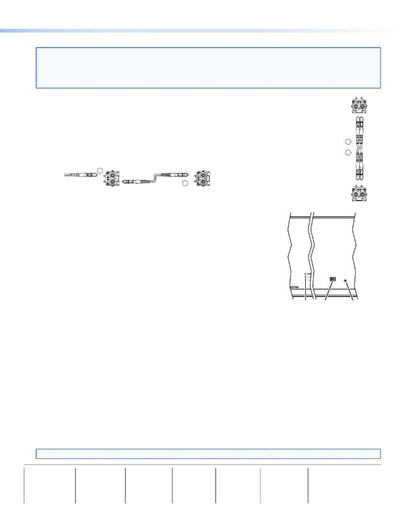
Step 3 — Throughput Connections
NOTE: See the two ber cable connection drawings below. You can connect the transmitter and one or more receivers in one
of three ways:
• One way (transmitter to receiver) only, perform step .3a
• Two way (transmitter to receiver and return), perform steps and .3a 3b
• One way (transmitter to receiver) with daisy chain (receiver to receiver), perform steps and .3a 3c
a. Connect the ber between the Tx port on the transmitter and the Rx port on the receiver.
b. If you want the receiver to send return serial data (such as responses from a controlled device) to the
transmitter, connect a cable between the Tx port on the receiver and Rx port on the transmitter.
c. If you want a receiver to daisy chain the optical signal to another receiver (up to 10 receivers in a daisy
chain):
• Connect the Tx ber cable on the receiver to Rx on another receiver.
• Set each receiver to daisy chain mode. See , below.Normal and Daisy Chain Modes
Fr
om Transmitter
or Daisy-Chained
Receiver
Receiver
Receiver
Tx Rx
Tx Rx
3a
3c
Step 4 — PowerCage Configuration Port
If desired, connect a host device to PowerCage enclosure Conguration connector via
the 9-pin D to 2.5 mm mini jack TRS RS-232 cable that is included with the PowerCage
enclosure or available separately using part #70-335-01. Repeatedly press the Comm Select
button until the Comm LED lights for the slot where the transmitter or receiver is installed.
The protocol for this port is as follows:
• 9600 baud • no parity • 8 data bits
• 1 stop bit • no ow control
Refer to the for detailed information about using the PowerCage FOX Tx/Rx User Guide
SIS commands and the Windows®-based FOX Extender program to set up and operate the
transmitter and receiver and to take advantage of the various adjustments and test patterns
available on the PowerCage FOX units.
Operation
After all receivers, the transmitter, and their connected devices are powered up, the system
is fully operational. If any problems are encountered, verify that the cables are routed and connected properly and that all display
devices have identical resolutions and refresh rates. If your problems persist, call the Extron S3 Sales & Technical Support Hotline
at the number shown below that is closest to you.
Normal and Daisy Chain Modes
The receiver operates on one of two modes:
• Normal mode — The receiver outputs RS-232 and SIS commands and responses on its Tx LC connector.
• Daisy chain mode — The receiver daisy chains its Rx connector input through to its Tx connector output.
Use SIS commands issued to the connected unit to toggle between normal and daisy chain modes. Connect a PC to the
Remote RS-232 port of either unit or to the Conguration port on the PowerCage enclosure and issue the following command:
66*0* #n
where:
n = 2 = enable daisy chain mode
n = 1 or 0 = disable daisy chain mode
NOTE: Up to 10 receivers, each in daisy chain mode, can be connected in a daisy chain to a single transmitter.
Receiver
Tr
ansmitter
Tx Rx
Tx Rx
and
3a
3b
COMM
1
POWER
ALARM
COMM
SELECT
CONFIG
Comm
Select
Button
Configuration
Port
Comm
LED
68-1911-51
Rev B
10 20
Extron USA - West
Headquarters
+800.633.9876
Inside U A / C a OS anad nly
+1.714.491.1500
+1.714.491.1517 FAX
Extron USA - East
+800.633.9876
Inside U A / C a OS anad nly
+1.919.863.1794
+1.919.863.1797 FA X
Extron Europe
+800.3987.6673
Inside Europe Only
+31.33.4 .453 040
+31.33.4 .453 050 FAX
Extron Asia
+800.7339.8766
Inside Asia Only
+65.6383.4400
+65.6383.4664 FAX
Extron Japan
+81.3.3511.7655
+81.3.3511.7656 FAX
Extron China
+400.883.1568
Inside C Ohina nly
+86.21.3760.1568
+86.21.3760.1566 FAX
Extron Middle East
+971.4.2991800
+971.4.2991880 FAX
© 2010 — 2020 Extron Electronics. All rights reserved. www.extron.com
2
PowerCage FOX Tx/Rx DVI Plus Setup Guide (Continued)
Product specificaties
| Merk: | Extron |
| Categorie: | AV extender |
| Model: | PowerCage FOX Tx DVI Plus |
| Kleur van het product: | Zwart |
| Gewicht: | 500 g |
| Gewicht verpakking: | 1000 g |
| Breedte verpakking: | 229 mm |
| Diepte verpakking: | 340 mm |
| Hoogte verpakking: | 67 mm |
| Soort: | AV-zender |
| LED-indicatoren: | Ja |
| Stroom: | 1 A |
| Connectiviteitstechnologie: | Bedraad |
| Ondersteunde video-modi: | 480p, 576p, 720p, 1080i, 1080p |
| Maximum resolutie: | 4096 x 2160 Pixels |
| Soort serieële aansluiting: | RS-232 |
| Certificering: | CE, C-tick, FCC Class A, ICES, VCCI |
| Ondersteunde grafische resoluties: | 640 x 480 (VGA),1920 x 1200 (WUXGA),3840 x 2160,4096 x 2160 |
| Duurzaamheidscertificaten: | RoHS |
| Audio (L,R) out: | 1 |
| Kleurdiepte: | 8 Bit |
| Temperatuur bij opslag: | -40 - 70 °C |
| Maximaal 30 frames per seconde: | 60 fps |
| Luchtvochtigheid bij opslag: | 10 - 90 procent |
| DVI input ports: | 1 |
| Bandbreedte: | 4.95 Gbit/s |
| Seriële poort(en): | 2 |
| Operating voltage: | 12 V |
| Maximaal bereik: | 30000 m |
| Stroomverbruik (typisch): | 5.68 W |
| Bedrijfstemperatuur (T-T): | 0 - 50 °C |
| Relatieve vochtigheid in bedrijf (V-V): | 10 - 90 procent |
| Ondersteunde golflengten: | 850,1310 nm |
| Baud snelheid: | 115.2 Kbit/s |
Heb je hulp nodig?
Als je hulp nodig hebt met Extron PowerCage FOX Tx DVI Plus stel dan hieronder een vraag en andere gebruikers zullen je antwoorden
Handleiding AV extender Extron

27 Oktober 2024
27 Oktober 2024
11 September 2024
5 September 2024
15 Augustus 2024
15 Augustus 2024
15 Augustus 2024
15 Augustus 2024
15 Augustus 2024
15 Augustus 2024
Handleiding AV extender
- AV extender Philips
- AV extender Abus
- AV extender Act
- AV extender Ag Neovo
- AV extender Allnet
- AV extender Audio Pro
- AV extender Belkin
- AV extender D-Link
- AV extender Digitus
- AV extender Dune
- AV extender Ebode
- AV extender Edimax
- AV extender Eminent
- AV extender Genexis
- AV extender Gigabyte
- AV extender Hama
- AV extender InFocus
- AV extender KEF
- AV extender Konig
- AV extender LevelOne
- AV extender Logilink
- AV extender Manhattan
- AV extender Marmitek
- AV extender Monacor
- AV extender Nedis
- AV extender Peerless
- AV extender Polycom
- AV extender Pyle
- AV extender Renkforce
- AV extender Roland
- AV extender Speaka
- AV extender Teufel
- AV extender Vivotek
- AV extender One For All
- AV extender Monoprice
- AV extender Schwaiger
- AV extender Steren
- AV extender Atlona
- AV extender Trevi
- AV extender Vivolink
- AV extender Techly
- AV extender SIIG
- AV extender Tripp Lite
- AV extender Approx
- AV extender Vision
- AV extender Matrox
- AV extender Gefen
- AV extender Planet
- AV extender Intellinet
- AV extender Lindy
- AV extender IOGEAR
- AV extender Black Box
- AV extender DataVideo
- AV extender Kindermann
- AV extender Bogen
- AV extender AJA
- AV extender Peerless-AV
- AV extender Marshall Electronics
- AV extender ATen
- AV extender Wentronic
- AV extender Dynaudio
- AV extender Adder
- AV extender Kopul
- AV extender MIPRO
- AV extender AMX
- AV extender Crestron
- AV extender I3-Technologies
- AV extender StarTech.com
- AV extender PureLink
- AV extender UTEPO
- AV extender Aitech
- AV extender Advantech
- AV extender Smart-AVI
- AV extender Kramer
- AV extender Micro Connect
- AV extender KanexPro
- AV extender Intelix
- AV extender ASSMANN Electronic
- AV extender Blustream
- AV extender Avocent
- AV extender Rose
- AV extender Accell
- AV extender Ecler
- AV extender Rose Electronics
- AV extender Epcom
- AV extender CYP
- AV extender TV One
- AV extender SmartAVI
- AV extender IMG Stage Line
- AV extender Oehlbach
- AV extender AVMATRIX
- AV extender HELGI
- AV extender Liberty
- AV extender Enson
- AV extender Lightware
- AV extender Alfatron
- AV extender SWIT
- AV extender Hall Research
- AV extender WyreStorm
- AV extender Rocstor
- AV extender Apantac
- AV extender MuxLab
- AV extender Seco-Larm
- AV extender ConnectPro
- AV extender Kanex
- AV extender TechLogix Networx
- AV extender C2G
- AV extender SEADA
- AV extender Comprehensive
- AV extender Analog Way
- AV extender Sescom
- AV extender DVDO
- AV extender Camplex
Nieuwste handleidingen voor AV extender
25 Februari 2025
20 Februari 2025
20 Februari 2025
7 Februari 2025
29 Januari 2025
13 Januari 2025
13 Januari 2025
13 Januari 2025
13 Januari 2025
13 Januari 2025