ZKSoftware TF1600 Handleiding
ZKSoftware
Vingerafdruklezer
TF1600
Lees hieronder de 📖 handleiding in het Nederlandse voor ZKSoftware TF1600 (4 pagina's) in de categorie Vingerafdruklezer. Deze handleiding was nuttig voor 24 personen en werd door 2 gebruikers gemiddeld met 4.5 sterren beoordeeld
Pagina 1/4
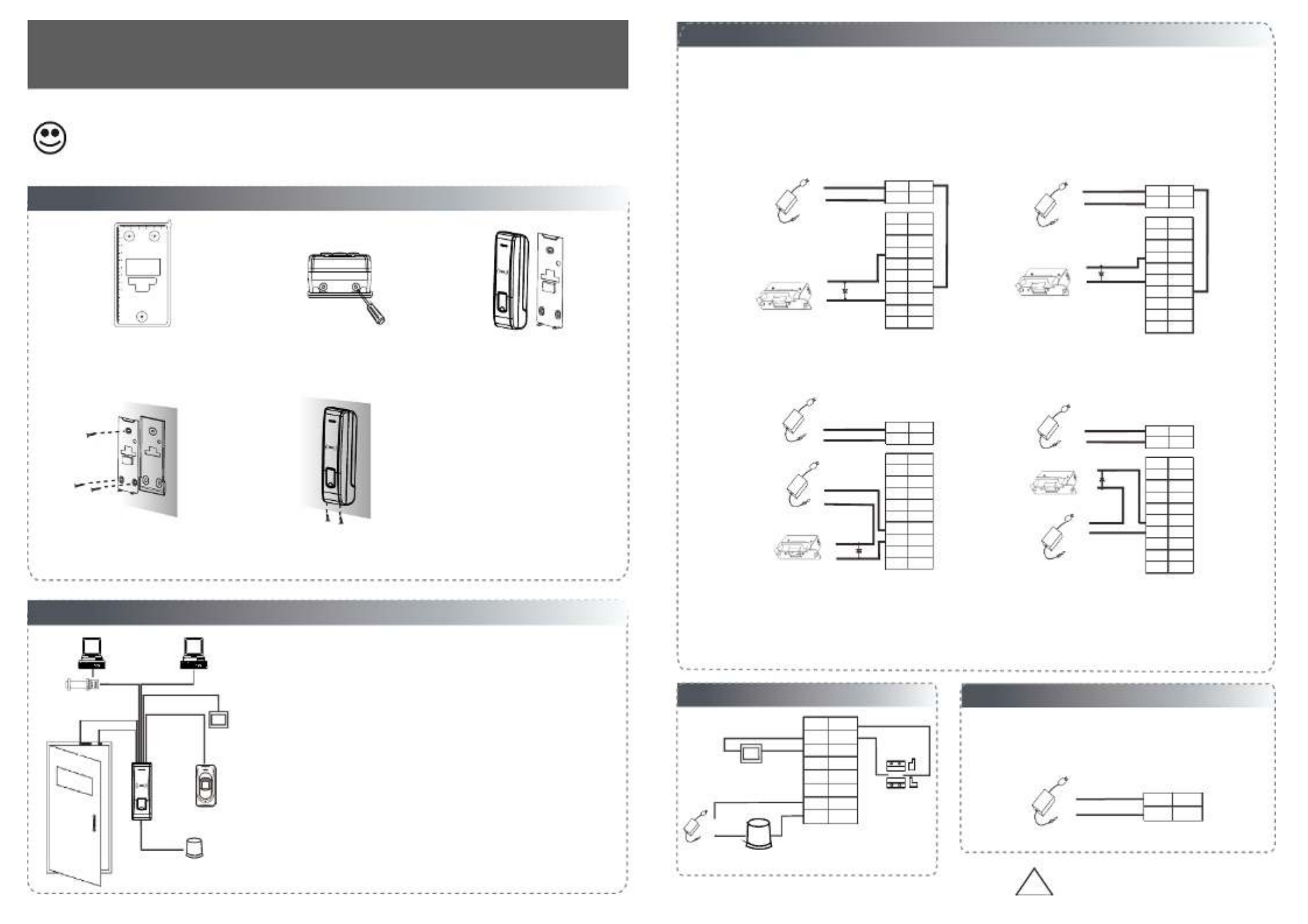
4. Other
4. Other
4. Other
4. Other4. Other Connections
Connections
Connections
ConnectionsConnections
1) Share power with the lock:
2) Does not share power with the lock:
Device does not share power with the lock :
①:‘I’: device output current, ‘ULOCK’: lock voltage,‘ILOCK’: lock current.
Device share power with the lock:
ULOCK=12V, I-ILOCK>1A And the distance between the lock and the device is 10 meters.…… ≤①;
A. ULOCK=12V, I-ILOCK 1A B ULOCK 12V C The distance between the lock and the device is >10 meters.≤ ; . ≠; .
3.
3.
3.
3.3.
Lock
Lock
Lock
LockLock Connection
Connection
Connection
ConnectionConnection
(1) The system supports NO lock and NC lock. For example the NO lock normally open at power on is connected with "NO" ( )
(2) When the electrical lock is connected to the Access Control System, you need to connect one FR107 diode (shipped in package) in
and "COM" terminals, and the NC lock is connected with "NC" and "COM" terminals.
parallel with the connection to prevent self-inductance EMF feedback the system.
NB: Do not reverse the polarities!
NC LOCK
+
-
NO LOCK
-
FR 107
-
+
DC12V
+
-
-
+
DC power
-
+
DC12V
-
+
DC power
+
-
FR 107
+
GND
NO1
NO2
COM2
BELL+
BUT
COM1
SEN
NC1
BELL-
Pu rp le
Brow n
Wh it e
Red
Black
Yellow
Gr ay
Or an ge
Blue
Gr ee n
GND
+12V
Red
Blac k
GND
NO1
NO2
COM2
BELL+
BUT
COM1
SEN
NC1
BELL-
Pu rp le
Brow n
Wh it e
Red
Black
Yellow
Gr ay
Or an ge
Blue
Gr ee n
GND
+12V
Red
Blac k
NC LOCK
-
+
DC12V
+
-
+
-
FR 107
NO LOCK
-
+
DC12V
+
-
+
-
FR 107
GND
NO1
NO2
COM2
BELL+
BUT
COM1
SEN
NC1
BELL-
Pu rp le
Brow n
Wh it e
Red
Black
Yellow
Gr ay
Or an ge
Blue
Gr ee n
GND
+12V
Red
Blac k
GND
NO1
NO2
COM2
BELL+
BUT
COM1
SEN
NC1
BELL-
Pu rp le
Brow n
Wh it e
Red
Black
Yellow
Gr ay
Or an ge
Blue
Gr ee n
GND
+12V
Red
Blac k
2.
2.
2.
2.2.Structure and Function
Structure and Function
Structure and Function
Structure and FunctionStructure and Function
Access Control System Function
(1) If a registered user verified, the device will send a signal to unlock the door.
(3) If the device is illegally removed, the device will signal the alarm.
(4) External card reader is supported.
(5) External exit button is supported.
(2) The door sensor will detect the ON OFF state. If the door is unexpectedly -
opened or improperly closed, the alarm signal (digital value) will be triggered.
(6) Supports RS485, TCP IP communication to be able to connect with a PC. One /
PC can manage multiple devices.
RS485 TCP/IP
Lock
Sensor
①
③
Alarm
RS485 Converter
②Exit Switch
⑤
External Reader
④
⑥
Exit
V
V
V
VVersion
ersion
ersion
ersionersion 1.1 Date
1.1 Date
1.1 Date
1.1 Date1.1 Date May
May
May
MayMay, 2013
, 2013
, 2013
, 2013, 2013
:
:
:
: : :
:
:
: :
I
I
I
IIn
n
n
nns
s
s
sst
t
t
tta
a
a
aal
l
l
lll
l
l
lla
a
a
aat
t
t
tti
i
i
iio
o
o
oon
n
n
nn G
G
G
GGu
u
u
uui
i
i
iid
d
d
dde
e
e
ee
1.
1.
1.
1.1.Equipment Installation
Equipment Installation
Equipment Installation
Equipment InstallationEquipment Installation
Wiri ng Hole
Instr uctio n f or the M oun ti ng Pape r
Instr uctio n f or the M oun ti ng Pape r
Instr uctio n f or the M oun ti ng Pape r
Instr uctio n f or the M oun ti ng Pape rInstr uctio n f or the M oun ti ng Pape r
Befor e the dev ice is fa stene d, plea se
Befor e the dev ice is fa stene d, plea se
Befor e the dev ice is fa stene d, plea se
Befor e the dev ice is fa stene d, plea seBefor e the dev ice is fa stene d, plea se
stick t p1-he pape r to the pl ace whe re you
stick t p1-he pape r to the pl ace whe re you
stick t p1-he pape r to the pl ace whe re you
stick t p1-he pape r to the pl ace whe re you
stick t p1-he pape r to the pl ace whe re you
want to i nstal l it, the n make ho les and
want to i nstal l it, the n make ho les and
want to i nstal l it, the n make ho les and
want to i nstal l it, the n make ho les and
want to i nstal l it, the n make ho les and
lay cab les acc ordin g to the mo untin g
lay cab les acc ordin g to the mo untin g
lay cab les acc ordin g to the mo untin g
lay cab les acc ordin g to the mo untin g
lay cab les acc ordin g to the mo untin g
paper.
paper.
paper.
paper.
paper.
Mo unt in g Pap er
(on ly for yo ur refe rence )
Fixi ng Hole
Fixi ng HoleFixi ng Hole
10
11
12
13
the wall. Drill the holes according
(1) Paste the mounting template on
to the marks on the template
( ).holes for screws and wiring
(2) Remove the screws on the
bottom of device .
2. Structure and Function
(5) Place the unit onto the mounting bracket, and
tighten the screws at the bottom of the unit.
plate on the wall according to
(4) Fix the rubber pad and the back
.the mounting paper
(3) Take away the back plate.
D. We suggest user does not share power with the lock.
Registering user information and fingerprint, we must use the ACCESS3.5
Software and fingerprint USB sensor, then upload .
Note:
* Reserves the final rights of modification and interpretation by our company.
Alarm Power
Exit Button
Door Sensor
-
+
Alarm
Alarm Voltage output DC 12V≤
GND
NO1
NO2
COM2
BUT
COM1
SEN
NC1
White
Red
Bla ck
Yellow
Gray
Orang e
Blu e
Green
Exit
!
WARNING: Do Not operate with Power connected.
5. Power Connection
5. Power Connection
5. Power Connection
5. Power Connection5. Power Connection
5 Power Connection:.
The device working voltage DC 12V, electric current 500mA
Positive is connected with‘+12V’;
negative is connect with ’GND’ ( ).do not reverse the polarities
+
DC12V
-
GND
+12V
Red
Black
(50mA for standby current).


There are two modes that the PC software communicate and exchange information with the device:
RS485 and TCP/IP, and supports remote control .
9. Communication
9. Communication
9. Communication
9. Communication9. Communication
(1) RS485 Mode:
Please use specified RS485 wire, RS232/485 active converter
and bus-type wiring. When the distance is long, it is need to 485 RS485+ +
Terminals PC Serial Ports
485 RS485- -
Terminals definition as below:
485+
485-
485+ 485-
RS Bus485
485+ 485- 485+ 485-
RS485
Converter
parallel a terminal resistance and the value is 120 ohm.
8
8
8
88 Other
Other
Other
OtherOther Functions & Features
Functions & Features
Functions & Features
Functions & FeaturesFunctions & Features
.
.
.
..
Front View Back View
Tamper
(1) Tamper Function:
When installing device, user need to put the magnet between the device
and the back plate. If the device is being illegally removed, the magnet
loses connectivity and will trigger the alarm.
Magnet
(3) fireproof material. Device mould is manufactured from
(4) Working temperature: -40℃ ℃.~ +45
(2) Restore Factory Settings:
Operation: Between 30 – 60 seconds after the tamper alarm has sounded,
press the tamper switch 3x times.
Access Control Panel
6. Wiegand Output
6. Wiegand Output
6. Wiegand Output
6. Wiegand Output6. Wiegand Output
The device supports standard Wiegand ,
various access control devices.
7. Wiegand Input
7. Wiegand Input
7. Wiegand Input
7. Wiegand Input7. Wiegand Input
to a slave card reader. Devices are control devices on both sides
The device has a Wiegand input port, which enables the connection
of the door to control the access and electric lock.
DATA0
GND
DATA1
GND
485+
WD1
WD0
485-
White
Black
Yellow
Blue
Green
GND
+12V
DATA1
DATA0
GLED
RLED
BEEP
IWD0
BEEP
GND
RLED
IWD1
GLED
+12V
Purple
White
Red
Black
Gray
Blue
Green
26-bit output, so you can connect it with
(1) Do not exceed 90m (meters) distance between the Device and Access Control Lock OR Card reader.
(In the case of long distance installation, use the Wiegand Signal Extender, to minimise interference.)
(2) To keep a balanced and stable Wiegand signal, connect the device, access control lock or card reader
on the same "GND"(ground) port.
* Reserves the final rights of modification and interpretation by our company.
10. Caution:
10. Caution:
10. Caution:
10. Caution:10. Caution:
( ) : A Crossover cable The device and PC connected directly.
(2) TCP/IP Mode:
Two ways for TCP/IP connection.
( )B Straight cable: The device and PC connected to
LAN/WAN through switch/Lanswitch.
IP Address 2 1 :192.168.1. 0
Subnet Mask :255.255.255.0
IP Address :192.168.1.124
Subnet Mask:255.255.255.0
Switch
…
Equipment supports RS485reader function, can be through RS485communication connected to FR1200 reader.
FR1200 reader for slaver, achieve RS485 Anti-passback functions. If select “RS485reader function” , so device
can not connect with PC through RS485 communications.
RS485 Reader Function:
Diagram of the device connect to reader as below(The device act master):
Reade r
Yel low
485-
485+
Purp le
Acc ess Co ntrol Device
Red
GN D
+12V
Black
(1) If the device is working abnormally, Connect the power cable after al the wiring has been completed.
please shut down the device, and make necessary checks. Please note that any "HOT SWOP" of wiring on
the device may damage the device, and the warranty does not cover damage caused by improper operations.
(2) We recommend . Please contact our technical staff for details.use the DC 12V/3A power supply
(3) Please read the terminal and wiring description and diagrams carefully before commencing with
installations. Any damage to the device caused by improper operations, will not be covered under warranty.
(4) , to avoid unexpected connection.Keep the exposed part of wire less than 5mm
(5) when starting installations, especially in an environment where static electricityPlease connect the 'GND'
is very high.
(6) in case of a long distance installations.Do not change the cable type
!
WARNING: Do Not operate with Power connected.
Diagram of the device connect to controller as below (The device act slaver):
Set the RS485 address (device number) by Access3.5 software.
+12V
GND
#3 R eader
485-
GND
485+
#1 Reade r #2 R eader #8 Rea der
...
STATE
PWR
EXTRS485 PCRS485
SWITCH
+12V
GND
(separate power supplies) (separate power supplies)
Product specificaties
| Merk: | ZKSoftware |
| Categorie: | Vingerafdruklezer |
| Model: | TF1600 |
| Kleur van het product: | Zwart |
| Internationale veiligheidscode (IP): | IP65 |
| Afmetingen (B x D x H): | 62.5 x 41.5 x 185 mm |
| Bedrijfstemperatuur (T-T): | -40 - 45 °C |
| Relatieve vochtigheid in bedrijf (V-V): | 20 - 80 procent |
Heb je hulp nodig?
Als je hulp nodig hebt met ZKSoftware TF1600 stel dan hieronder een vraag en andere gebruikers zullen je antwoorden
Handleiding Vingerafdruklezer ZKSoftware

28 Oktober 2023
Handleiding Vingerafdruklezer
- Vingerafdruklezer Hikvision
- Vingerafdruklezer Media-tech
- Vingerafdruklezer Suprema
- Vingerafdruklezer ZKTeco
- Vingerafdruklezer Perfect Choice
Nieuwste handleidingen voor Vingerafdruklezer
15 November 2023
26 Juni 2023
18 Juni 2023
9 Juni 2023

18 April 2023