Vimar 03832 Handleiding
Vimar Alarmsysteem 03832
Bekijk gratis de handleiding van Vimar 03832 (1 pagina’s), behorend tot de categorie Alarmsysteem. Deze gids werd als nuttig beoordeeld door 93 mensen en kreeg gemiddeld 4.0 sterren uit 6 reviews. Heb je een vraag over Vimar 03832 of wil je andere gebruikers van dit product iets vragen? Stel een vraag
Pagina 1/1
Viale Vicenza, 14
36063 Marostica VI - Italy
www.vimar.com
49401784A0 01 2212
03832
BY-ALARM PLUS
Scheda ricetrasmettitore By-alarm Plus, collegamento in radiofrequenza 868
MHz, connesso alla centrale via BUS, 2 antenne per polarizzazione orizzontale
e verticale in antenna-diversity.
La scheda ricetrasmettitore, attraverso la quale vengono integrati nell'impianto i rivelatori e i tele-
comandi radiofrequenza, è un dispositivo bidirezionale che permette di espandere il numero delle
zone della centrale mediante collegamento al BUS. Va installata assieme alla centrale 03800-
03801-03802 nella scatola 03814 o in quella di adattamento centralino 03816.
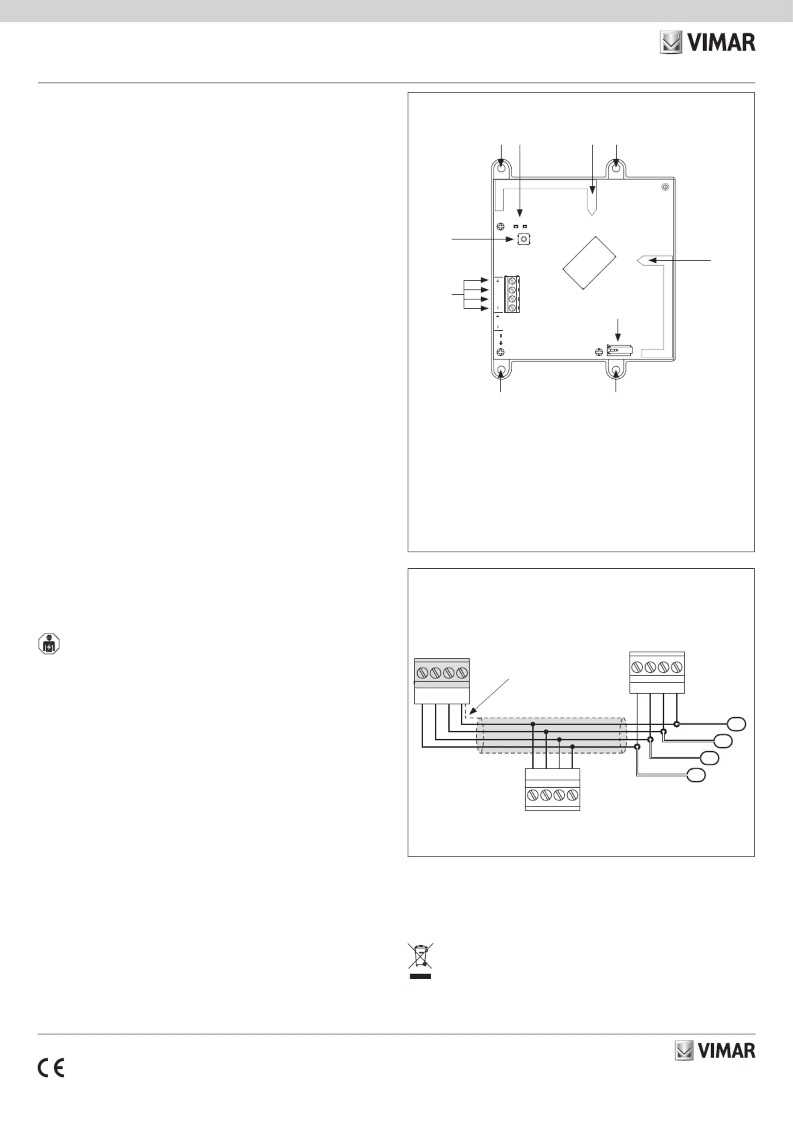
COLLEGAMENTI
Il collegamento con la centrale va effettuato con un cavo schermato a 4 (o più) fili.
Attenzione: La calza va collegata ad uno dei morsetti di massa (o GND) solo dal lato della
centrale e deve seguire tutto il BUS senza essere collegata a massa in altri punti.
Il collegamento della scheda va effettuato sui morsetti “+ D S -” della centrale.
SEGNALAZIONI DEI LED
• Se la centrale è in fase di arruolamento delle periferiche BUS e il ricetrasmettitore NON è stato
ancora indirizzato, i LED 1 e 2 lampeggiano alternativamente.
• Se la centrale è in fase di arruolamento delle periferiche BUS e il ricetrasmettitore E' stato
indirizzato, i LED 1 e 2 visualizzano l’indirizzo assegnato al dispositivo, ossia:
- il LED 2 lampeggia un numero di volte pari alle decine dell’indirizzo assegnato;
- il LED 1 lampeggia un numero di volte pari alle unità dell’indirizzo assegnato.
• Se la centrale NON è in fase di arruolamento delle periferiche BUS:
- il LED 1 lampeggia continuamente per indicare che il dispositivo sta funzionando corretta-
mente;
- il LED 2 emette un lampeggio ogni volta che riceve il segnale di un dispositivo radio.
INSTALLAZIONE
Per un ottimale funzionamento dei dispositivi via radio, posizionare ill dispositivo il più centrale
possibile rispetto alla distribuzione dei sensori e all’area di utilizzo dei telecomandi.
1. Scegliere la posizione più idonea all’installazione della centrale.
2. Aprire il coperchio del contenitore che alloggia la centrale.
3.Fissare la scheda ricetrasmettitore:
- nel caso si utilizzi l'art. 03814, fissare la staffa plastica alle tre colonne mediante le viti autofi-
lettanti fornite in dotazione (si veda anche il foglio istruzioni dell'art. 03814);
- nel caso si utilizzi l'art. 03816, avvitare i tre distanziali in metallo e poi fissare la staffa plasti-
ca su tali distanziali mediante le viti metriche in dotazione (si veda anche il foglio istruzioni
dell'art.03816).
5. Cablare la scheda ricetrasmettitore.
6. Effettuare la procedura di indirizzamento del ricetrasmettitore.
7. Chiudere il coperchio frontale della centrale.
8. Mediante il software By-alarm Plus Manager attivare l'opzione "No sabotaggio".
CONFIGURAZIONE
Per tutti i dettagli si vedano i manuali di installazione del sistema By-Alarm Plus e del software
By-alarm Plus Manager.
REGOLE DI INSTALLAZIONE
L’installazione e la configurazione devono essere effettuate da personale qualificato con l’osser-
vanza delle disposizioni regolanti l’installazione del materiale elettrico in vigore nel paese dove i
prodotti sono installati.
Si sconsiglia il montaggio su superfici ferromagnetiche, e nelle vicinanze di forti campi magnetici
ed elettrici, in quanto questi potrebbero provocare il malfunzionamento del dispositivo.
CARATTERISTICHE
• Tensione di alimentazione dal bus: da 9 a 15 V
• Corrente assorbita: 12 mA
• Bande di frequenza:
- 868.0 MHz - 868.6 MHz
- 868.8 MHz - 869.0 MHz
• Potenza RF trasmessa: 25mW e.r.p.
• Numero max di ricetrasmettitori gestibili dalla centrale art. 03800-03801-03802: 5
• Numero max di ripetitori art. 03840 in serie gestibili dal ricetrasmettitore: 1
• Modulazione: GFSK
• Supervisione dispositivi: da 12 a 250 minuti
• Doppia antenna per soluzione diversity
• Installazione su scatola art. 03814 o 03816
• Temperatura di funzionamento: da -10 a +40 °C
• Umidità relativa: 93% senza condensazione≤
• Grado di sicurezza: 2
• Classe d’isolamento: II
• Dimensioni (L x A x P): 127 x 127 x 35 mm
• Peso: 140 g
CONFORMITA' NORMATIVA.
Direttiva RED. Direttiva RoHS.
Norme EN 62368-1, EN 50130-4, EN 50130-5, EN 55032, EN 50131-3, EN 301 489-3, EN 300
220-2, EN 62479, EN IEC 63000.
N.B. Installare il dispositivo nel verso di figura.
A: Morsetti +, D, S, - per il collegamento del BUS
B: Pulsante di configurazione
C: Staffe per fissaggio su scatola 03814 o 03816
D: LED 1 e LED 2
E: Antenna
F: Microswitch antisabotaggio
COLLEGAMENTI
VISTA FRONTALE
RAEE - Informazione agli utilizzatori
Il simbolo del cassonetto barrato riportato sull’apparecchiatura o sulla sua confezione indica che il prodotto alla fine della propria
vita utile deve essere raccolto separatamente dagli altri rifiuti. L’utente dovrà, pertanto, conferire l’apparecchiatura giunta a fine
vita agli idonei centri comunali di raccolta differenziata dei rifiuti elettrotecnici ed elettronici. In alternativa alla gestione autonoma,
è possibile consegnare gratuitamente l’apparecchiatura che si desidera smaltire al distributore, al momento dell’acquisto di una
nuova apparecchiatura di tipo equivalente. Presso i distributori di prodotti elettronici con superficie di vendita di almeno 400 m
2
è
inoltre possibile consegnare gratuitamente, senza obbligo di acquisto, i prodotti elettronici da smaltire con dimensioni inferiori a
25 cm. L’adeguata raccolta differenziata per l’avvio successivo dell’apparecchiatura dismessa al riciclaggio, al trattamento e allo
smaltimento ambientalmente compatibile contribuisce ad evitare possibili effetti negativi sull’ambiente e sulla salute e favorisce il
reimpiego e/o riciclo dei materiali di cui è composta l’apparecchiatura.
Vimar SpA dichiara che l’apparecchiatura radio è conforme alla direttiva 2014/53/UE. Il testo
completo della dichiarazione di conformità UE è disponibile nella scheda di prodotto al seguente
indirizzo Internet: www.vimar.com.
Regolamento REACh (UE) n. 1907/2006 – art.33. Il prodotto potrebbe contenere tracce di
piombo.
1234
J6
J5
SW
SH1
P1/ENR
DL1
12
DL2
56
DS12V
A
B
CD
F
EC
E
CC
D+–S
D+–S
D+–S
S
–
D
+
Centrale
03800
03801
03802
BUS
Calza
Altri dispositivi
BUS
Scheda
Ricestrasmettitore
03832
Product specificaties
| Merk: | Vimar |
| Categorie: | Alarmsysteem |
| Model: | 03832 |
Heb je hulp nodig?
Als je hulp nodig hebt met Vimar 03832 stel dan hieronder een vraag en andere gebruikers zullen je antwoorden
Handleiding Alarmsysteem Vimar

2 Juli 2025
2 Juli 2025
2 April 2025
2 April 2025
2 April 2025
2 April 2025
2 April 2025
1 April 2025
1 December 2024
1 December 2024
Handleiding Alarmsysteem
Nieuwste handleidingen voor Alarmsysteem
10 Juli 2026
27 Mei 2026
5 Mei 2026
4 April 2026
2 April 2026
2 April 2026
1 April 2026
1 April 2026
10 Maart 2026
10 Maart 2026