Vimar 03806 Handleiding
Vimar Alarmsysteem 03806
Bekijk gratis de handleiding van Vimar 03806 (2 pagina’s), behorend tot de categorie Alarmsysteem. Deze gids werd als nuttig beoordeeld door 75 mensen en kreeg gemiddeld 4.0 sterren uit 8 reviews. Heb je een vraag over Vimar 03806 of wil je andere gebruikers van dit product iets vragen? Stel een vraag
Pagina 1/2
Viale Vicenza, 14
36063 Marostica VI - Italy
www.vimar.com
49401669A0 01 2212
03806
BY-ALARM PLUS
Alimentatore By-alarm Plus con uscita 13,8 Vd.c. 6,2 A, alimentazione 230 V~
50/60 Hz.
Il dispositivo fornisce una tensione stabilizzata a 13,8 V ed una corrente massima di 5 A erogata
ai morsetti “+V” e “-V”. Le uscite sono protette da sovraccarichi, corto circuiti ed inversione
accidentale delle polarità dell’eventuale batteria collegata. L’alimentatore è dotato di una sonda
termica che adatta la tensione di ricarica delle batterie alla loro temperatura in modo da ottenere
una ricarica più efficiente. I componenti utilizzati garantiscono idonei requisiti di funzionamento
quando le condizioni ambientali esterne al contenitore della centrale o al centralino in cui è instal-
lato l'alimentatore sono in accordo con la classe 3k5 della normativa EN 60721-3-3.
COLLEGAMENTI
• Collegare i conduttori provenienti dalla rete elettrica alla morsettiera di ingresso A.
• Se l’alimentatore è utilizzato per alimentare centrali 03800, 03801 o 03802 , collegare il cavo
in dotazione al connettore D; l’altro capo del cavo deve essere collegato al connettore posto
sulla scheda della centrale.
• Collegare al connettore G il capo a 3 conduttori del cavo fornito in dotazione.
• Se viene utilizzata una batteria tampone al piombo ricaricabile, collegare il cavo in dotazione al
connettore B; l’altro capo del cavo deve essere collegato alla batteria rispettando le polarità.
• La tensione di uscita può essere prelevata o dai morsetti [C] (“+V, -V”), o dal connettore [D]
(“+V, -V”).
• Sul connettore di uscita inoltre sono presenti i terminali “FAULT” e “RTH” riservati alla connes-
sione con le centrali 03800, 03801 e 03802.
• Per installare la sonda termica collegare la sonda al connettore E. Posizionare la sonda a
contatto con una delle batterie assicurandosi di ottenere una buona conducibilità termica.
Sonda termica (opzionale)
E' disponibile una sonda termica per la compensazione della tensione di ricarica della batteria in
funzione della temperatura di quest'ultima. Utilizzando tale sonda si previene il surriscaldamento
della batteria ed il suo conseguente danneggiamento.
Per la connessione della sonda termica effettuare quanto segue:
• Scollegare la batteria.
• Collegare la sonda termica al connettore sull’alimentatore E.
• Fissare la sonda termica alla batteria in modo da ottenere una buona trasmissione del calore.
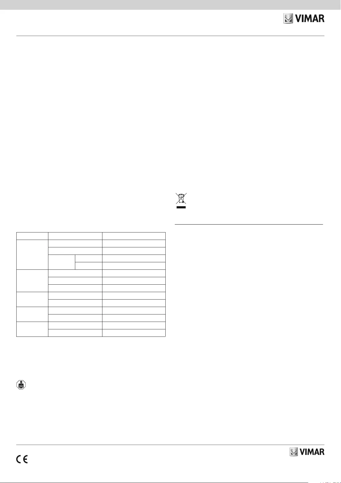
SEGNALAZIONI DEI LED
I led segnalano la presenza della tensione di rete ed il corretto funzionamento dell’alimentatore
e delle batterie.
N.B. Dal connettore “STATUS” [F] si possono prelevare le segnalazioni di guasto tramite due
uscite Open Collector “OC1” e “OC2”.
LedModalità Significato
DL1 - Verde
SpentoAlimentatore spento
AccesoAlimentatore in funzione
Lampeggiante
velocementeSurriscaldamento
lentamenteSovraccarico uscite
DL2 - Giallo
SpentoCorretto funzionamento della rete
AccesoGuasto funzionamento di rete
Lampeggiante velocementeGuasto di terra
DL3 - Giallo
SpentoCorretto funzionamento delle batterie
AccesoGuasto batterie
Uscita OC1
SpentoCorretto funzionamento
AccesoGuasto alimentatore
Uscita OC2
SpentoCorretto funzionamento della rete
AccesoGuasto funzionamento di rete
Il disinserimento del ponticello sui connettori per la segnalazione dei guasti di terra [I] disattiva
il controllo del guasto di terra. In caso di utilizzo in abbinamento a centrali di sicurezza tutte le
segnalazioni obbligatorie di stato e di guasto devono essere previste e rese disponibili in centrale.
BATTERIE
Le batterie di backup non sono fornite. L'installatore deve utilizzare esclusivamente batterie al
piombo-acido regolate da valvola (VRLA) per uso stazionario, conformi alle norme IEC 60896-21
ed IEC 60896-22. La batteria deve avere involucro antifuoco V-2 o superiore.
REGOLE DI INSTALLAZIONE
• L’installazione deve essere effettuata da personale qualificato con l’osservanza delle dispo-
sizioni regolanti l’installazione del materiale elettrico in vigore nel paese dove i prodotti sono
installati.
• L'alimentatore deve essere installato all’interno di un involucro antifuoco (ad esempio il conte-
nitore della centrale).
• Per il fissaggio all’interno di contenitori od apparecchiature utilizzare i due semifori di fissaggio J.
• A monte della connessione con l’alimentatore è necessario installare un idoneo dispositivo di
sezionamento (bipolare) e di protezione nell’impianto elettrico in accordo con le norme vigenti
(DM37/08).
ATTENZIONE: E’ necessario collegare il conduttore di terra. I conduttori provenienti dalla rete
elettrica devono essere fascettati e fissati in prossimità del loro ingresso all'alimentatore. I
cavi utilizzati per il cablaggio del prodotto devono avere sezione adeguata ed essere conformi
alla norma IEC 60332-1-2 o alla IEC 60332-2-2.
CARATTERISTICHE
• Tensione di alimentazione: 230 V~ (-15%/+10%), 50/60Hz
• Corrente assorbita: 1,1 A (max)
• Tensione d’uscita: 13,8 V (±1%)
• Tensione d’uscita di funzionamento: da 9 a 13,8 V
• Tensione di sgancio batteria: 9,5 V
• Ripple massimo sulla tensione d’uscita: 1%
• Corrente massima in uscita totale: 6,2A
- per carico esterno: 5 A
- per ricarica batteria: 1,2 A
• Batteria collegabile: (o equivalente con classe infiammabilità involucro UL94-V2 o superiore):
12V – 7Ah o 17Ah YUASA NP-12 FR
• Fusibile (F1) non sostituibile: T 3,15A 250V
• Resistenza interna batteria massima: 2,7 Ω
• Temperatura di funzionamento: da -5 a +40 °C
• Classe d’isolamento: I
• Dimensioni (L x A x P): 200 x 51 x 99 mm
• Peso: 0,8 Kg
CONFORMITA' NORMATIVA.
Direttiva BT. Direttiva EMC. Direttiva RoHS.
Norme EN 62368-1, EN 50131-6, EN 50130-4, EN 50130-5, EN 55032, EN 61000-3-2, EN
61000-3-3, EN IEC 63000.
Regolamento REACh (UE) n. 1907/2006 – art.33. Il prodotto potrebbe contenere tracce di
piombo.
RAEE - Informazione agli utilizzatori
Il simbolo del cassonetto barrato riportato sull’apparecchiatura o sulla sua confezione indica che il prodotto alla fine della
propria vita utile deve essere raccolto separatamente dagli altri rifiuti. L’utente dovrà, pertanto, conferire l’apparecchiatura
giunta a fine vita agli idonei centri comunali di raccolta differenziata dei rifiuti elettrotecnici ed elettronici. In alternativa alla
gestione autonoma, è possibile consegnare gratuitamente l’apparecchiatura che si desidera smaltire al distributore, al mo-
mento dell’acquisto di una nuova apparecchiatura di tipo equivalente. Presso i distributori di prodotti elettronici con superficie
di vendita di almeno 400 m
2
è inoltre possibile consegnare gratuitamente, senza obbligo di acquisto, i prodotti elettronici
da smaltire con dimensioni inferiori a 25 cm. L’adeguata raccolta differenziata per l’avvio successivo dell’apparecchiatura
dismessa al riciclaggio, al trattamento e allo smaltimento ambientalmente compatibile contribuisce ad evitare possibili ef-
fetti negativi sull’ambiente e sulla salute e favorisce il reimpiego e/o riciclo dei materiali di cui è composta l’apparecchiatura.
By-alarm Plus power supply unit with 13.8 Vdc 6.2 A output, 230 V~ 50/60
Hz input.
This device supplies a stabilised voltage of 13.8 V with a maximum current of 5 A at the “+V”
and “-V” terminals. The outputs are protected against overloads, short circuits and accidental
polarity reversal of any battery connected. The power supply unit has a temperature probe to
adapt the battery charging voltage to the battery temperature in order to make charging more
efficient. The components used meet suitable operating requirements when the environmental
conditions outside the control unit enclosure or switchboard in which the power supply unit is
installed correspond to class 3k5 of standard EN 60721-3-3.
CONNECTIONS
• Connect the mains power conductors to the input terminal block A.
• If the power supply unit is used to power control units 03800, 03801 or 03802, connect the
cable provided to the connector D; connect the other end of the cable to the connector on
the control unit board.
• Connect the end of the 3-conductor cable provided to the connector G.
• If a rechargeable lead buffer battery is used, connect the cable provided to the connector B;
connect the other end of the cable to the battery, taking care to observe the polarity.
• The output voltage can be taken from the terminals [C] (“+V, -V”), or from the connector [D]
(“+V, -V”).
• There are also “FAULT” and “RTH” terminals on the output connector, which are reserved for
connecting control units 03800, 03801 and 03802.
• To install the temperature probe, connect the probe to the connector E. Place the probe so
that it is touching one of the batteries, and make sure that there is good thermal conductivity.
Temperature probe (optional)
A temperature probe is available to adjust the battery charging voltage to compensate the
battery temperature. Using this probe prevents the battery from overheating, which would
damage it.
To connect the temperature probe, proceed as follows:
• Disconnect the battery.
• Connect the temperature probe to the connector E on the power supply unit.
• Secure the temperature probe to the battery in such a way as to ensure good heat transfer.
Product specificaties
| Merk: | Vimar |
| Categorie: | Alarmsysteem |
| Model: | 03806 |
Heb je hulp nodig?
Als je hulp nodig hebt met Vimar 03806 stel dan hieronder een vraag en andere gebruikers zullen je antwoorden
Handleiding Alarmsysteem Vimar

2 Juli 2025
2 Juli 2025
2 April 2025
2 April 2025
2 April 2025
2 April 2025
2 April 2025
1 April 2025
1 December 2024
1 December 2024
Handleiding Alarmsysteem
Nieuwste handleidingen voor Alarmsysteem
23 Juli 2026
23 Juli 2026
21 Juli 2026
10 Juli 2026
27 Mei 2026
5 Mei 2026
4 April 2026
2 April 2026
2 April 2026
1 April 2026