Speco Technologies H6WHRLN Handleiding
Speco Technologies
Videorecorder
H6WHRLN
Lees hieronder de 📖 handleiding in het Nederlandse voor Speco Technologies H6WHRLN (102 pagina's) in de categorie Videorecorder. Deze handleiding was nuttig voor 48 personen en werd door 2 gebruikers gemiddeld met 4.5 sterren beoordeeld
Pagina 1/102

HRLN (6/16/24 Channel DVR)
User Manual
H6HRLN
H16HRLN
H24HRLN
Version 1.0
Features and specicaons are subject to change, please check www.specotech.com for rmware updates.

Notes& Contents DVR User Manual
Notes
Please read this user manual carefully to ensure that you can use the device correctly and safely.
The contents of this manual are subject to change without noce.
Do not install this device near any heat sources such as radiators, heat registers, stoves or other devices that produce heat.
Do not install this device near water. Clean only with a dry cloth.
Do not block any venlaon openings and ensure proper venlaon around the machine.
Do not power o the device during normal recording operaon.
This machine is for indoor use only. Do not expose the machine to rain or install in a moist environment. In case any solid or liquid parcles get
inside the machine’s case, please turn o the device immediately and get it checked by a qualied technician.
Do not aempt to repair this device yourself.

Notes& Contents DVR User Manual
Contents
1 Introducon............................................................................................................................................................................................... 1
1.1 Welcome ........................................................................................................................................................................................................... 1
1.2 Features ............................................................................................................................................................................................................. 1
1.3 Front Panel Descripons ................................................................................................................................................................................... 4
1.4 Rear Panel Descripons ..................................................................................................................................................................................... 4
1.5 Connecons....................................................................................................................................................................................................... 4
2 Basic Operaon Guide ............................................................................................................................................................................... 5
2.1 Startup & Shutdown .......................................................................................................................................................................................... 5
2.1.1 Startup .................................................................................................................................................................................................... 5
2.1.2 Shutdown ............................................................................................................................................................................................... 5
2.2 Remote Control ................................................................................................................................................................................................. 5
2.3 Mouse Control ................................................................................................................................................................................................... 6
2.4 Text-input Instrucon ........................................................................................................................................................................................ 6
2.5 Common Buon Operaon ............................................................................................................................................................................... 7
3 EZ Setup & Main Interface ......................................................................................................................................................................... 8
3.1 EZ Setup............................................................................................................................................................................................................. 8
3.2 Main Interface ................................................................................................................................................................................................. 12
3.2.1 Main Interface Introducon ................................................................................................................................................................. 12
3.2.2 Setup Panel ........................................................................................................................................................................................... 14
3.2.3 Main Funcons ..................................................................................................................................................................................... 15
4 Camera Management .............................................................................................................................................................................. 17
4.1 Camera Signal .................................................................................................................................................................................................. 17
4.2 Add/Edit Camera ............................................................................................................................................................................................. 17
4.2.1 Add Camera .......................................................................................................................................................................................... 17
4.2.2 Edit Camera .......................................................................................................................................................................................... 18
5 Live View Introducon ............................................................................................................................................................................. 20
5.1 Live View Interface Introducon ..................................................................................................................................................................... 20
5.2 View Mode ...................................................................................................................................................................................................... 21
5.2.1 Display Mode ........................................................................................................................................................................................ 21
5.2.2 Quick Sequence View ........................................................................................................................................................................... 22
5.2.3 Scheme View In Sequence .................................................................................................................................................................... 23
5.2.4 Spot View ............................................................................................................................................................................................. 23
5.3 Image Conguraon ........................................................................................................................................................................................ 24
5.3.1 OSD Sengs ......................................................................................................................................................................................... 24

Notes& Contents DVR User Manual
10.7 View Online User ........................................................................................................................................................................................... 71
11 Device Management ................................................................................................................................................................................ 72
11.1 Network Conguraon .................................................................................................................................................................................. 72
11.1.1 TCP/IP Conguration .......................................................................................................................................................................... 72
11.1.2 Port Conguraon .............................................................................................................................................................................. 72
11.1.3 PPPoE Conguraon ........................................................................................................................................................................... 74
11.1.4 DDNS Conguraon ............................................................................................................................................................................ 74
11.1.5 E-mail Conguraon ........................................................................................................................................................................... 74
11.1.6 UPnP Conguraon ............................................................................................................................................................................ 75
11.1.7 802.1X ................................................................................................................................................................................................ 76
11.1.8 NAT Conguraon .............................................................................................................................................................................. 76
11.1.9 Plaorm Access .................................................................................................................................................................................. 76
11.1.10 View Network Status ........................................................................................................................................................................ 77
11.2 Basic Conguraon ........................................................................................................................................................................................ 77
11.2.1 General Conguraon ........................................................................................................................................................................ 77
11.2.2 Date and Time Conguraon.............................................................................................................................................................. 78
11.2.3 Recorder OSD Sengs ........................................................................................................................................................................ 79
11.3 Factory Default .............................................................................................................................................................................................. 79
11.4 Device Soware Upgrade .............................................................................................................................................................................. 79
11.5 Backup and Restore ....................................................................................................................................................................................... 80
11.6 Restart Automacally .................................................................................................................................................................................... 80
11.7 View Log ........................................................................................................................................................................................................ 80
11.8 View System Informaon .............................................................................................................................................................................. 81
12 Remote Surveillance ................................................................................................................................................................................ 82
12.1 Mobile Client Surveillance ............................................................................................................................................................................. 82
12.2 Web LAN Access ............................................................................................................................................................................................ 82
12.3 Web WAN Access .......................................................................................................................................................................................... 83
12.4 Web Remote Control ..................................................................................................................................................................................... 83
12.4.1 Remote Preview ................................................................................................................................................................................. 84
12.4.2 Remote Playback ................................................................................................................................................................................ 87
12.4.3 Remote Export .................................................................................................................................................................................... 87
12.4.4 Intelligent Analysis .............................................................................................................................................................................. 88
12.4.5 Remote Conguraon ........................................................................................................................................................................ 88
Appendix A FAQ .................................................................................................................................................................................................. 89
Appendix B Calculate Recording Capacity ............................................................................................................................................................ 94
Appendix C Specicaons ................................................................................................................................................................................... 95

Introducon DVR User Manual
1
1 Introducon
1.1 Welcome
Thank you for purchasing this DVR.
If technical assistance is needed, please contact Speco Technologies Technical Support.
Phone: 1-800-645-5516 opon 3
Email: techsupport@specotech.com
1.2 Features
Basic Funcons
Supports network device access including IP camera/dome and ONVIF IP cameras
This recorder supports H.265 and H.264 IP cameras
Supports standard ONVIF protocol
Supports dual stream recording of each camera
Supports IP cameras to be added quickly or manually
Supports collecve or individual conguraon of the cameras’ OSD, video parameters, mask, moon and so on
Supports a maximum of 8 user permission groups including Administrator, Advanced and Common which are the default permission groups of
the system
Supports a maximum of 16 users to be created, mulple web client login by using one username at the same me and the user’s permission
control to be enabled or disabled
Supports mulple web client’s login at the same me
Live View
Supports 4K×2K/1920×1080/1280×1024 HDMI and 1920×1080/1280×1024 VGA high-denion synchronous display
Supports mul-screen modes such as 1/4/6/8/16
Supports auto adjustment of the camera’s image display proporon
Supports enabling or disabling of audio monitoring of a camera
Supports manual snapshot of a camera
Supports display modes to be added and saved and the saved modes can be recalled directly
Supports quick tool bar operaon of the preview window
Supports scheme view in sequence, quick sequence view and sequence interval setng
Supports moon detecon and video mask
Supports mulple popular PTZ control protocols and setup of preset and cruise
Supports direct mouse control of the IP dome including rotang, zoom, focusing and so on
Supports single camera image zoom by sliding the scroll wheel of the mouse

Introducon DVR User Manual
2
Supports any area of the image to be zoomed in to a maximum of 16 mes of the current size
Supports image and lens adjustment (only available for some cameras)
Supports quick camera adding in the camera window of the live view interface
Disk Management
H16HRL/H24HRL supports 2 SATA HDDs
H6HRL supports 1 SATA HDD
Supports 1 e-SATA HDD
Each SATA interface of the DVR supports HDDs with max 16TB storage capacity
Supports disk group conguraon and management and each camera can be added into dierent disk groups with dierent storage capacity
Supports disk informaon and disk operang status viewing
Supports formang disks in batch
Recording Conguraon
Supports main stream and sub stream recording at the same me and collecve or individual conguraon of the record stream
Supports manual and auto record modes
Supports schedule recording, sensor alarm recording and moon detecon recording, etc
Supports schedule recording and event recording setng with dierent record streams
Supports record schedule seng and recycle recording
Supports prerecording and delay recording conguraon of event recording
Recording Playback
Supports me scale operaon in quick playback and the playback date and me can be set randomly by scrolling the mouse; the me interval
of the me scale can be zoomed
Supports record searching by me slice/me/event/tag
Supports me view and camera view in searching by EZ mode
Supports EZ search by month, by day, by hour and by minute and me slice to be displayed with camera thumbnail
Supports a maximum of 16 cameras to be searched by me
Supports event search by manual/moon/sensor/intelligent events
Supports bookmark search by the manual added bookmarks
Supports instant playback of the selected camera in the live view interface
Supports a maximum of 16 synchronous playback cameras
Supports acceleraon(maximum 32 times of the normal speed), deceleraon (minimum 1/32 mes of the normal speed) and 30s’ addion or
reducon to current playing me
Record Export
Supports recording export through USB (U disk, mobile HDD).
Supports recording export by me/event/image search
Supports cung of recording for exporng while playing back
Supports a maximum of 10 export tasks in background and export status viewing

Introducon DVR User Manual
3
Alarm Management
Supports alarm schedule seng
Supports enabling or disabling of the moon detecon, external sensor alarm input, intelligence alarm and excepon alarms including IP
address conict alarm, disk IO error alarm, disk full alarm, no disk alarm, illegal access alarm, network disconnecon alarm, IPC oine alarm and so
on, alarm trigger conguraon supportable
Supports IPC oine alarm trigger conguraon of PTZ, snapshot, pop-up video, etc.
Supports event nocaon modes of alarm-out, pop-up video, pop-up message box, buzzer, e-mail and so on
Captured images can be aached into an e-mail when alarm linkage is triggered
Supports alarm status view of alarm-in, alarm-out, moon detecon and excepon alarm
Supports manual alarm triggering and clearing
Supports system auto reboot when an excepon happens
Network Funcons
Supports TCP/IP and PPPoE, DHCP, DNS, DDNS, UPnP, NTP, SMTP protocol and so on
Supports allow and block list funcon and the allow and block IP address/IP segment address can be set
Supports mulple browsers including IE8/9/10/11, Firefox, Opera, Chrome (available only for the versions lower than 45) and Safari in MAC
system
Supports remote achievement, conguraon, import and export of the DVR parameters and other system maintenance operaons including
remote upgrading and system restart
Supports remote camera conguraon of the DVR including video parameters, image quality and so on
Supports remote search, playback and export of the DVR
Supports manual alarm triggering and clearing
A motorized zoom camera can be adjusted through web client (Supports zoom in/out, but one key focus is not currently supported)
Supports NAT funcon and QRCode scanning by mobile phone andTablet
Supports mobile surveillance by phones or Tablets with iOS or Android OS
If one camera recording is enabled or disabled manually through web client, it will be simultaneously enabled or disabled in the DVR
Other Funcons
The DVR can be controlled and operated by the buons on the front panel (where applicable), the remote control and the mouse
Seng interfaces can be switched to one another conveniently by clicking the main menus on the top of the seng interfaces
Supports DVR informaon viewing including basic, camera status, alarm status, record status, network status, disk and export status
Supports factory restoring, import and export of the system conguraon, log view and export and local upgrading by USB mobile device
Supports auto recognition of the displayer’s resoluon
You can click the right mouse buon at any interface to go back to the main interface
You can click the mouse wheel at any interface to go to the live view interface
The display language and video format of the DVR will not be changed and the system logs will be reserved if you reset the DVR to factory
default
Press and hold the right mouse buon for 5 seconds in any interface to switch the output

Introducon DVR User Manual
4
1.3 Front Panel Descripons
The following descripons are for reference only.
Name Descripons
REC When recording the light is blue
Net When you have access to a network the light is blue
Power Power indicator: when powered the light is blue
1.4 Rear Panel Descripons
To quickly get started, connect the following to your recorder in the following order. Please refer to the following gure (H24HRL shown for reference).
1. Connect analog cameras to the video input ports (BNC) of the recorder.
2. Connect a monitor to the recorder via VGA or HDMI cable (not included).
3. Connect the included opcal mouse into any USB port of the recorder.
4. Connect the power adapter to the recorder and plug power cord into a 120VAC 50/60Hz outlet.
5. Connect recorder to network (oponal, but necessary if you plan to use IP cameras or connect to recorder remotely)
1.5 Connecons
Video Connecons
Video Input Supports BNC video input. :
Video Output: Supports CVBS/VGA/HDMI video output. You can connect to a monitor through these video output interfaces simultaneously or
independently.
Audio Connecons
Audio Input: Connect to microphone, pickup, etc.
Audio Output: Connect to headphone, sound box or other audio output devices.

Basic Operaon Guide DVR User Manual
5
2 Basic Operaon Guide
2.1 Startup & Shutdown
Please make sure all the connecons are done properly before you power on the unit. Proper startup and shutdown are crucial to extendingthe life
of your device.
2.1.1 Startup
① Connect the output display device to the VGA/HDMI interface of the DVR.
② Connect to the mouse and power. The device will boot and the power LED will turn blue.
③ EZ setup window will pop up (you should select the display language the rst time you use the DVR). Refer to 3.1 EZ Setup for details.
2.1.2 Shutdown
You can power o the device by using remote control or mouse.
By remote control:
① Press Power buon. This will take you to a shutdown window. The unit will power o aer a while by clicking the “OK” buon.
② Disconnect the power.
By mouse:
① Click Start Shutdown to pop up the Shutdown window. Select “Shutdown” in the window. The unit will power o aer a while by clicking the
“OK” buon.
② Disconnect the power.
2.2 Remote Control
① It uses two AAA size baeries.
② Open the baery cover of the remote control.
③ When adding baeries check for the polarity (+ and -).
④ Replace the battery cover.
Key points to check in case the remote doesn’t work.
1. Check baery polarity.
2. Check the remaining charge in the batteries.
3. Check IR controller sensor for any obstrucons.
If it sll doesn’t work, please contact your distributor or Speco Technologies’ tech support. You can just turn the IR sensor of the remote control
towards the IR receiver of the DVR to control it when you are controlling mulple devices by remote control.
The remote control interface is shown on the following page.

Basic Operaon Guide DVR User Manual
6
2.3 Mouse Control
Mouse control in Live Display & Playback interface
In the live display & playback interface, double click on any camera window to show the window in single screen mode; double click the window
again to restore it to the previous size.
In the live display & playback interface, if the interface display is in full screen, move the mouse to the boom of the interface to pop up a tool bar.
The tool bar will disappear automacally aer you move the mouse away from it; move the mouse to the right side of the interface to pop up a
panel and the panel will disappear automacally aer you move the mouse away from it.
Mouse control in text-input
Move the mouse to the text-input box and then click the box. The input keyboard will pop up automacally.
2.4 Text-input Instrucon
Buon Funcon
Power Button Switch o—to stop the device
Record Button To start recording
-/-- /0-9 Input number or choose camera
Fn1 Buon No funcon temporarily
Mul Button To choose mul screen display mode
Next Button To switch the live image
SEQ To go to sequence view mode
Audio To enable audio output in live mode
Switch No funcon temporarily
Direcon buon To move cursor in setup or pan/tle PTZ
Enter Buon To conrm the choice or setup
Menu Buon To go to menu
Exit Buon To exit the current interface
Focus/IRIS/Zoom/PTZ To control PTZ camera
Preset Buon To enter into preset seng in PTZ mode
Cruise Buon To go to cruise seng in PTZ mode
Track Buon No track funcon temporarily
Wiper Buon No funcon temporarily
Light Buon No funcon temporarily
Clear Buon No funcon temporarily
Fn2 Buon No funcon temporarily
Info Button Get informaon about the device
To control playback.
Play (
Pause)/Stop/Previous
Frame/Next Frame/Speed Down/Speed Up
Snap Buon To take snapshots manually
Search Button To go to search mode
Cut Buon No funcon temporarily
Backup Buon To go to backup mode
Zoom Button To zoom in the images
PIP Buon Not acve
Note: Mouse is the default tool for all operations unless an exception as indicated.

Basic Operaon Guide DVR User Manual
7
The system includes two input boxes. Refer to the above pictures. The le box is the number input box and the right box is the input box which
provides inputs of numbers, letters and punctuaon characters. The legend of input box keys is shown below.
Buon Meaning Buon Meaning
Backspace key Switch key of punctuaon character
Delete Key Enter key
Switch key between upper
and lower leer Space key
Switch key of language
2.5 Common Buon Operaon
Buon Meaning
Click to show the menu list.
Click to change the sequence of the list.
Click to change the camera display mode.
Click to close the current interface.
Click to go to the earliest date of camera recording.
Click to go to the latest date of camera recording.
EZ Setup & Main Interface DVR User Manual
8
3 EZ Setup & Main Interface
3.1 EZ Setup
The disk icons will be shown on the top of the startup interface. You can view the number and status of each disk quickly and conveniently through
these icons ( : no disk; : unavailable disk; : RW available disk).
You must congure the wizard if you start the DVR for the rst me (or click “Skip” to cancel the EZ Setup next me).
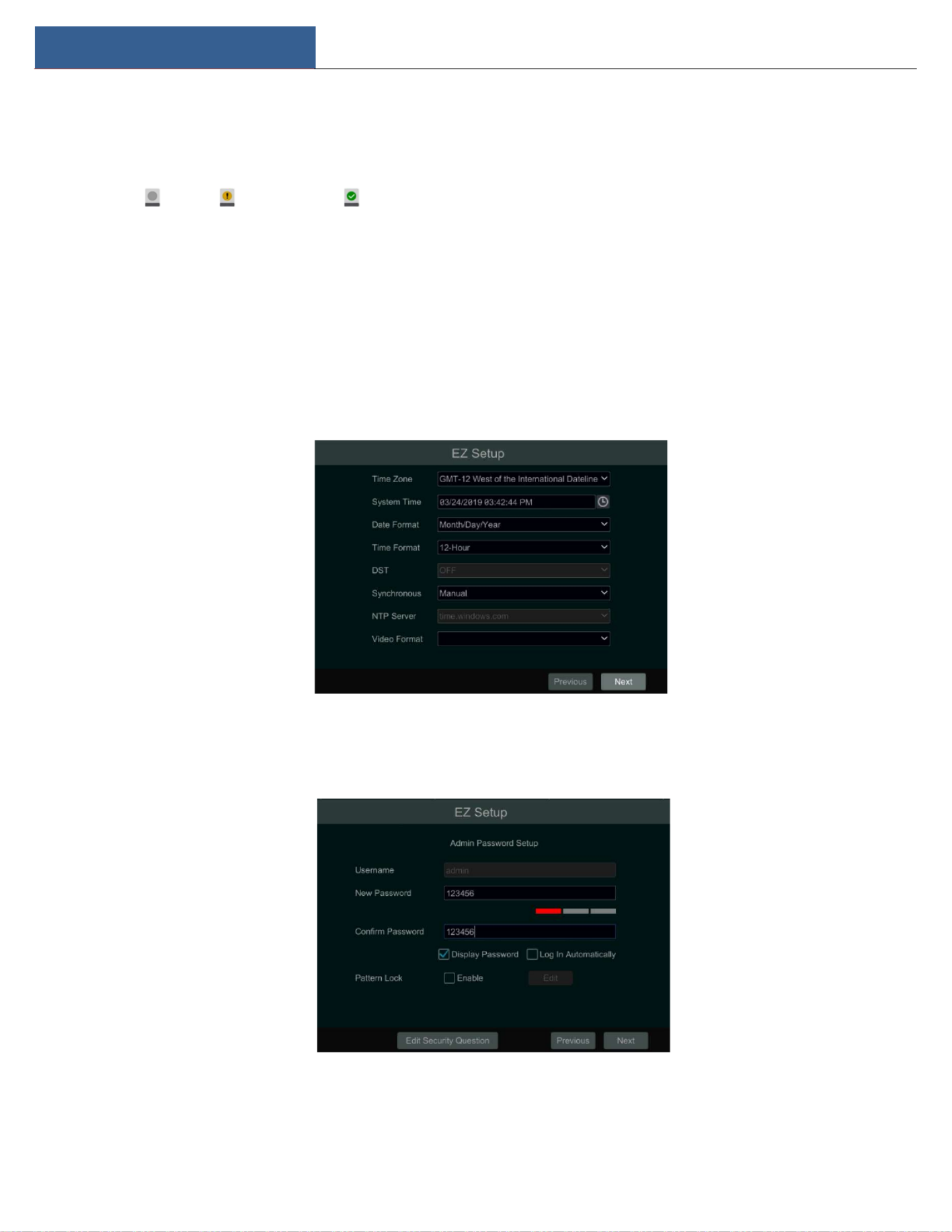
The rst me you start up your DVR, you should choose the language and locality as needed. Aer that, you will congure date and me.
System Time: Set the me and date format of the system
DST: Toggle Daylight Saving Time On or O
Time format: Choose between 24-hour mode and 12-hour mode.
NTP: Specify an NTP server to synchronize the me (oponal).
Click “Next” to connue.
System Login. Set your own password when you use the wizard for the rst me; select the login username and enter the corresponding password
next me.

EZ Setup & Main Interface DVR User Manual
9
Enable paern lock and click “Edit” to set the paern lock.
Click “Edit Security Queson” to set quesons and answers for password security of admin. If you forget the password, please refer to Q4 in
Appendix A FAQ for details.
Click “Next” to connue.
Aer you log in, you will see an EZ setup interface as shown below.
Click “OK” to start wizard. The EZ Setup steps are as follows.
① System Login. Set your own password when you use the wizard for the rst me (the default username of the system is ); select the admin
login username and enter the password you set by yourself.

EZ Setup & Main Interface DVR User Manual
10
Click “Next” to connue or click “Cancel” to exit the wizard.
② Network Sengs. Select the network conguraon as required. Check “Obtain an IP address automacally” and “Obtain DNS automacally”
to get the IP address and DNS automacally (the DHCP funcon of the router in the same LAN should also be enabled), or manually enter them.
Enter the HTTP port, RTSP port and Server port (please see 12.1.2 Port Conguraon for details). Click “Next” to connue.
③ Other Network Sengs.
UPnP sengs: Check “Enable” in the interface and enter the external port and then click “Test”. If the UPnP status is “Invalid UPnP”, the port
number may be wrong. Click to modify the port unl the UPnP status turns to “Valid UPnP”. Refer to the following picture. You can
view the external IP address of the DVR. Enter the external IP address plus port in the address bar of your browser to access the DVR. (Please
see 11.1.6 UPnP Conguraon for details).
DDNS Sengs: Check “Enable” and then select the DDNS type. Enter the server address, domain name, username, and password according to
the selected DDNS type and then click “Register” or “Test” to test the eecveness of the domain name. If it is eecve, you can enter the
domain name in the address bar of your browser to access the DVR. (Please see 11.1.4 DDNS Conguraon for details).
Note: Make sure the router supports UPnP funcon and the UPnP is enabled in the router. Set the DVR’s IP address, subnet mask and gateway and
so on corresponding to the router.

EZ Setup & Main Interface DVR User Manual
11
④ Add Camera.To add cameras from the LAN, make sure all cameras are set to DHCP. Click “Refresh” to refresh the list of online IP cameras
which are in the same local network with DVR and then click to add the searched camera. Click “Add All” to add all the cameras in the list.
Click to delete the added camera. Click “Delete All” to delete all the added cameras.
Click to edit the searched IP camera as shown below le. Enter the new IP address, subnet mask, gateway, username, and the password of
the camera. You can check “Sync to IPC” to modify the IP address of the IPC via dierent network segments for being in the same network segment
with the DVR. Click “OK” to save the sengs.
Click to edit the added camera as shown above right. Enter the new camera name, IP address, port, username, and the password of the
EZ Setup & Main Interface DVR User Manual
12
camera. You can click “Test” to test the eecveness of the inpued informaon. Click “OK” to save the sengs. You can change the IP camera
name only when the added camera is online. Click “Next” to connue.
⑤ Disk Sengs. You can view the disk number, disk capacity of the DVR and serial number, R&W status of the disk. Click “Formang” to format
the disk. Click “Next” to continue.
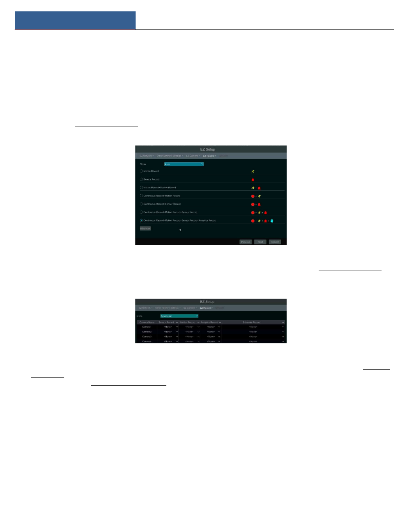
⑥ Record Sengs. Two record modes are available: auto and scheduled.
Auto: Select one auto mode in the interface as shown below and then click “Next” buon to save the sengs. Click “Advanced” to self-define
record mode. See 7.1.1 Mode Conguraon for details.
Scheduled: Set the “Sensor Record”, “Moon Record” and “Schedule Record” of each camera. Click “OK” to save. See 7.1.1 Mode Conguraon for
details.
⑦ QRCode. Enable the NAT funcon in the interface or set it in the network conguraon aer exing the wizard (please refer to 11.1.8 NAT
Conguraon for details). You can scan the QRCode through the Speco Blue App available for iOS and Android to easily and securely view your
cameras. Please refer to 12.1 Mobile Client Surveillance for details. Click “OK” to save the setngs.
3.2 Main Interface
3.2.1 Main Interface Introducon

EZ Setup & Main Interface DVR User Manual
13
The buons in area ① are introduced in the table below.
Buon Meaning
Start button. Click to pop up area ③.
Full screen buon. Click to show full screen; click it again to exit the full screen.
Screen mode buon.
Sequence buon (see 5.2.2 Quick Sequence View and 5.2.4 Scheme View in Sequence
for details).
Click to enable OSD; click again to disable OSD.
Click to set the default playback me before starng instant playback (8.1 Instant
Playback) or going to the playback interface for playback operaons (8.2 Playback
Interface Introducon); click to go to the playback interface. For instance, if you
choose “5 minutes ago” as the default playback me, you can playback the recording
from the past ve minutes.
Manual record button. Click to enable/disable record.
Manual alarm buon. Click to trigger or clear the alarm-out manually in the popup
window.
Record status button. Click to view the record status.
Alarm status button. Click to view the alarm status.
Disk status button. Click to view the disk status
Network status buon. Click to view the network status.
Informaon buon. Click to view system informaon.
Introducon of area ②:
Click “Camera” to view all the added cameras in the camera list. Select one camera window on the le side of the interface and then double click

EZ Setup & Main Interface DVR User Manual
14
one camera in the list to preview the camera image in the selected window.
Click “Customize Layout” to view all the display modes in the display mode list (refer to 5.2.1 Display Mode for detailed conguraon of the display
mode). Double click one display mode in the list to switch to the display mode for previewing.
Introducon of area ③:
Icon / Buon Meaning
Shows the current login user.
Click to go to recording search and export interface, see 8.4 Record Search,
Playback & Export for details.
Click to go to playback interface (click on the tool bar at the boom of the
live view interface to set the default playback me), see 8.2 Playback Interface
Introduconfor details.
Click to pop up the setup panel, see 3.2.2 Setup Panel for details.
Click to log out the system.
Click and then select “Logout”, “Reboot” or “Shutdown” in the popup window.
Click to go to the EZ setup.
3.2.2 Setup Panel
Click Start Seings to bring up the setup panel as shown below.
The setup panel includes seven modules. Each module provides some funcon entries with links for convenient operaon.

EZ Setup & Main Interface DVR User Manual
15
Here we take module as an example. The module provides convenient links such as “Add Camera”, “Edit Camera”, “Image Sengs”, Camera Camera
“Moon”, “Intelligence Analycs” and “PTZ”. Click to go to the camera management interface as shown below. Camera
There are some funcon items on the le side of the camera management interface. Click each item to go to corresponding interface or window.
For instance, click “Add Camera” to pop up the window as shown below.
Click the main menus on the top of the camera management interface to go to corresponding interfaces. Refer to the picture below. For instance,
you can go to the system setup interface by clicking “System” tag.
3.2.3 Main Funcons
Camera
This module covers funcons such as (see Chapter 4 Camera Management for details), (see 5.3 Image Camera Management Image Sengs
Conguraon for details), (see 9.2.1 Moon Conguraon for details), and (see Chapter 6 PTZ for details) and so on. Moon PTZ
Record
This module covers funcons such as and and so on. Please see Chapter 7 Record & Disk Management for Encode Parameters Record Schedule
details.

EZ Setup & Main Interface DVR User Manual
16
Alarm
This module covers funcons such as and . Please see Chapter 9 Alarm Management for Sensor and Motion Alarm Handling Alarm Out Sengs
details.
Disk
This module covers funcons such as , and and so on. Please see Chapter 7 Record & Disk Disk Management Storage Mode Disk Informaon
Management for details.
Network
This module covers funcons such as TCP/IP DDNS Port E-mail Network Status, , , and and so on. Please see 11.1 Network Conguraon for details.
Account and Authority
This module covers funcons such as (see 10.1 Account Management for details) and (see 10.3 Account Management Permission Management
Permission Management for details) and so on.
System
This module covers funcons such as (see 11.2 Basic Conguration for details), Basic Conguraon Device Informaon (see 11.8 View System
Informaon for details), (see 11.7 View Log for details) and (see 11.5 Backup and Restore for Log Informaon Conguraon File Import&Export
details) and so on.

Live View Introducon DVR User Manual
17
4 Camera Management
4.1 Camera Signal
Click Start Seings Camera Manage Camera Camera Signal to go to the interface as shown below.
Some models may support switching analog signals to IP signals, which means decreasing (or increasing) the number of analog channels will
accordingly increase (or decrease) the number of IP channels.
The DVR supports hybrid access of TVI, and CVBS high-denion cameras. If the TVI high-denion camera is attached to the DVR, you should
select TVI/CVBS in the following interface to show the camera image normally; if you select AHD/CVBS, then there will be no image or the image
will have no color. The default selecon of the camera signal is Auto. If you select Auto, the image of the camera will be shown normally regardless
of the camera type.
Audio over Coax: if your analog camera supports coaxial audio transmission, you can select “ON”. For now, coaxial audio transmission is only
available for TVI output.
Note: You can enable “Lite” in the interface if the DVR supports “Lite” recording. It will lower the recording resoluon and increase the recording
frame rate. Please enable or disable the Lite funcon as needed.
4.2 Add/Edit Camera
4.2.1 Add Camera
The network of the DVR should be congured before adding IP cameras (see 12.1.1 TCP/IP Conguraon for details).
Refer to the pictures below. Click in the setup panel or in the top right corner of the preview window to pop up the “Add Add Camera
Camera” window as shown below. You can quickly add or add the IP camera manually.

Live View Introducon DVR User Manual
18
Quickly Add
Check the cameras and then click “Add” to add cameras. Click to edit the camera’s IP address, username, and password and so on. Click
“Default Password” to set the default username and password of each camera.
Add Manually
Enter the IP address or domain name (click in the IP address column to pop up the domain name input window, enter the domain name of
the IPC in the window and then click “OK” buon), port, username and password of the camera and then select the protocol. Click “Test” to test
the effecveness of the input information and then click “Add” buon (you can input one camera’s informaon or above such as IP address,
username, and password before clicking “Add” buon). Click to delete the camera. Click “Default Password” to set the default username and
password of each camera.
4.2.2 Edit Camera
Click “Edit Camera” in the setup panel to go to the interface as shown below. Click to view the live image of the camera in the popup window.
Click to edit the camera (see in 3.1 Startup Wizard for details). Click to delete the camera. Click in the “Operaon” Add camera

Live View Introducon DVR User Manual
19
header line and then click “Modify IPC Password” to pop up a window (check the IPCs in the window, set the new password and then click “OK”
buon; only the online IPCs passwords can be modied, though a batch of IPCs passwords can be modied at the same me). Click to
upgrade an online IPC ( or click in the “Upgrade” header line and then click “IPC Batch Upgrade” to upgrade a batch of IPCs), select the device
which stores the upgrade le in the “Device Name” item of the popup window and the upgrade le in the list(you should select the upgrade IPC
model in the window if a batch of IPCs’ passwords need to be modied) and then click “Upgrade” buon to start upgrading(the IPC will restart
automacally aer the upgrade is completed successfully).

Live View Introducon DVR User Manual
20
5 Live View Introducon
5.1 Live View Interface Introducon
As shown in the interface below, you can drag one camera in the preview window to another window to exchange preview locaon in the grid.
The recording symbols with dierent colors in the live view window refer to dierent recording types when recording: green stands for manual
recording, red stands for sensor based recording, yellow stands for moon based recording, blue stands for schedule recording and cyan stands for
intelligent recording.
Click the preview window to show the tool bar as shown in area ①; right click the preview window to show the menu list. The tool bar and menu
list are introduced in the table below.
Buon Menu List Meaning
-- Move tool. Click to move the toolbar anywhere.
Manually Record On Click to start recording.
Instant Playback Click to playback the recording; click “Instant Playback” to select or
self-dene the instant playback me. See 8.1 Instant Playback for details.
Enable Audio Click to enable audio. You can listen to the camera audio by enabling audio.
Snap Click to pop up the snap window. Click “Save” in the window to save the
image. Click “Export” to export the image.
PTZ Control Click to go to PTZ control interface. See Chapter 6 PTZ for details.
Zoom In Click to go to single channel zoom interface.
-- Click to go to image adjustment interface. Refer to 5.4.5 Image Adjustment
for details.
-- Camera Info Click to view the camera informaon.

Live View Introducon DVR User Manual
21
The single channel zoom interface is as shown below. Press and drag the blue box to select the zoom in area. Click / to zoom the
image. Click the camera selecon box to select other cameras for magnicaon. Click “Back” to return to the live view interface.
5.2 View Mode
5.2.1 Display Mode
Set dierent screen modes and cameras’ display sequences as needed and then save the display modes classied by surveillance areas, priories
and so on. Refer to the picture below. Double click one display mode in the display mode list to view the live images in this mode.
Add Display Mode
Method One:
① Click “Customize Display Modes” in the above interface and then set the screen mode.

Live View Introducon DVR User Manual
22
② Add the cameras and adjust the cameras’ display sequence as needed.
③ Click under the display mode list and then enter the display mode name in the popup window, click the “OK” buon to save the current
display mode.
Method Two:
① Click Start Seings System Basic Output Sengs to go to the interface and then set the screen mode.
② Double click the camera or camera group in the list to add them to the selected window.
③ Click to save the current display mode (refer to 5.2.4 Scheme View In Sequence for detail conguraons). The display mode will be saved
and displayed in the display mode list in the live view interface.
Edit Display Mode
Click “Customize Layout” tab in the live view interface and then select one display mode in the list. Click to edit the display mode name; click
to delete the display mode.
5.2.2 Quick Sequence View
You can start quick sequence view if the scheme has not been created. If the scheme has been created, please refer to 5.2.4 Scheme View in
Sequence for details.
Go to the live view interface and then click to pop up a small window. Set the dwell me in the window and then click to view the live
group by group according to the camera number of the current screen mode. Double click the sequence view interface to pause the view; double
click again to restore the view. Click to stop the view.

Live View Introducon DVR User Manual
23
5.2.3 Scheme View In Sequence
Click Start Seings System Basic Output Sengs to go to the interface as shown below.
Area ① displays all the sequence schemes; area ② shows the detailed informaon of the scheme; area ③ displays all the cameras and groups;
area ④ is the tool bar ( : clear buon; : favorite buon, click it to pop up a window, enter the display mode name in the window and then
click “OK” to save the current display mode; other buttons are screen mode buons).
Add Scheme
Click in area ① to create a new scheme. Click on the top right corner of the scheme to delete it.
Congure Scheme
a) Select a scheme in area ① and then click the screen mode buon on the tool bar to set the screen mode of the scheme.
b) Select a camera window in area ② and then double click the camera or group in area ③. The camera or group will be added into the
selected window. One camera in the same scheme cannot repeat. You can click the right-click menu “Clear” in area ② to remove a single camera
or click to remove all the cameras.
c) Click “Apply” to save the sengs.
Start Sequence View
Go to the live view interface and then click to open a window. Set the sequence interval in the window and then click to start scheme
view in sequence. Double click the sequence view interface to pause the view; double click again to restore the view. Click to stop the view.
5.2.4 Spot View
Click Start Seings System Basic Output Sengs Output 2 to go to the interface as shown below.

Live View Introducon DVR User Manual
24
Click on the le to create a new scheme. Each scheme can only add one analog camera. Select a scheme on the le and then double click or
drag a camera on the right to the scheme window in the middle of the interface. Aer nishing the sengs of all the schemes, select the sequence
interval and click “Apply” to start playing the schemes in sequence in output 2.
5.3 Image Conguraon
5.3.1 OSD Setngs
Click Start Sengs Camera Image OSD Sengs to go to the interface as shown below. Select the camera, enter the camera name (or double
click the camera name in the camera list to change the camera name), enable or disable the name and me OSDs (if enabled, drag the red name
and me OSDs directly in the image view area to change the OSDs’ display posion) and select the date, me format and color. Click “Apply” to
save the sengs.

Live View Introducon DVR User Manual
25
5.3.2 Image Sengs
Click Start Sengs Camera Image Image Sengs to go to the following interface. Select the camera and then set the brightness, contrast,
saturaon, and hue of the camera. Click “Advanced” buon or in the camera list on the right side of the interface to pop up the “Image
Adjust” interface and then set the relevant seng items. Please refer to 5.4.5 Image Adjustment for detailed introducons of these items.
You can click “Default” to restore the image sengs to the default factory sengs.
5.3.3 Mask Setngs
Some areas of the image can be masked for privacy. Up to four mask areas can be set for each camera. Click
Start Setngs Camera Image Mask Sengs to go to the interface as shown below. Select the camera and enable the mask. Click “Draw”
buon and then drag the mouse on the image area to set the mask area; click “Delete” button to delete the mask areas; click “Apply” to save the
sengs.
5.3.4 Water Mark Sengs
Click Start Sengs Camera Image Water Mark Sengs to go to the interface as shown below. Select the camera and enable water mark and
then enter the water mark informaon. Click “Apply” to save the sengs.

Live View Introducon DVR User Manual
26
5.3.5 Image Adjustment
Go to the live view interface and then click buon on the tool bar under the camera window to go to the image adjustment interface.
Image Adjustment
Select the camera and then click “Image Adjustment” to go to image adjustment tab. Refer to the above picture. Drag the slider to set the camera’s
brightness, contrast, saturaon and hue value. Check sharpen, wide dynamic and denoise and then drag the slider to set the value. Click “Default”
buon to set these parameters to default values.
The introducons of these parameters are as follows:
Parameter Meaning
Brightness Brightness level of the camera’s image.
Contrast Color difference between the brightest and darkest parts.
Saturaon Degree of color purity. The color is purer, the image is brighter.
Hue Relates to the total color degree of the image.
PTZ DVR User Manual
29
6 PTZ
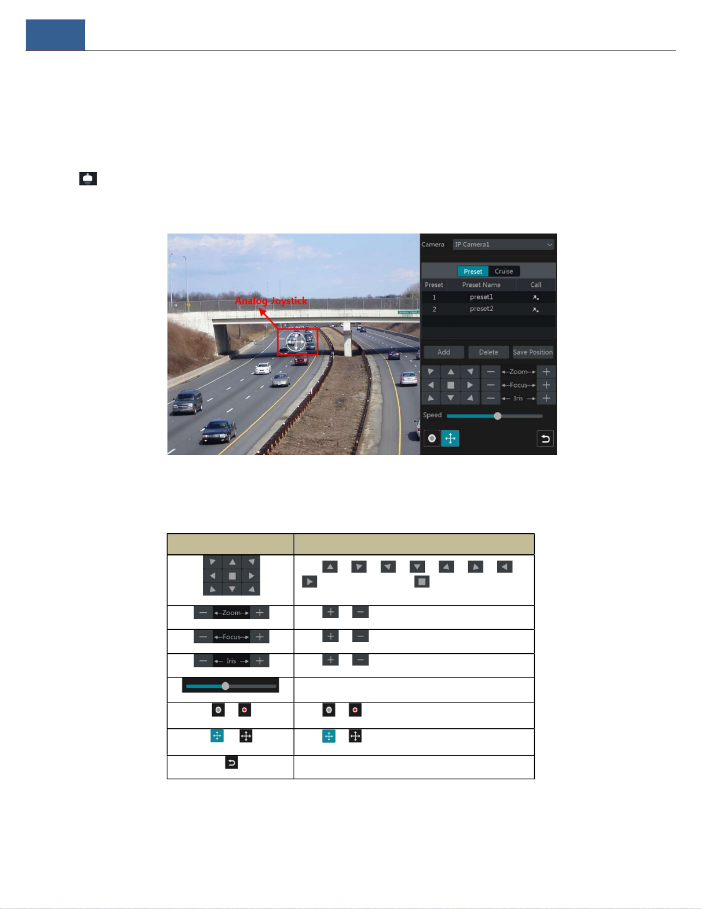
6.1 PTZ Control Interface Introducon
You can control the IP dome or PTZ camera for PTZ control.
Click on the tool bar at the boom of the live view window to go to the PTZ control interface as shown below. You can select another IP
dome or PTZ which connects to the IP camera on the top right of the interface for PTZ control.
Guide to the buons on the boom right of the interface:
Buon Meaning
Click / / / / / / /
to rotate the dome. Click to stop rotang the dome.
Click / to zoom in / out on camera image.
Click / to increase / decrease the focal length.
Click / to increase / decrease the iris of the dome.
Drag the slider to adjust the rotang speed of the dome.
/ Click / to start / stop recording.
/ Click / to hide / show the analog joysck.
Click to return to the live view interface.
Analog Joysck Control
The analog joystick on the le side of the interface provides quick PTZ control. The dome or PTZ will rotate when you drag the analog joysck. The

PTZ DVR User Manual
30
further you drag the analog joysck from the middle of the image, the faster the dome or PTZ rotates. The dome or PTZ will stop rotang when you
stop dragging the analog joysck.
3D Control
Click the camera image on any area and then the image will be centered on the clicked point.
Refer to the picture as shown below. Drag the mouse from A to B to get a green rectangle and the rectangular area will zoom in.
Refer to the picture as shown below. Drag the mouse from C to D to get a green rectangle and the rectangular area zoom out.
Advanced 3D Control
Double click the le buon of the mouse on any area of the camera image to make the image size double and be centered on the clicked point.
Press and hold the le buon of the mouse on any area of the camera image to zoom in on the image; press and hold the right buon to zoom out

PTZ DVR User Manual
31
of the image.
Move the cursor of the mouse to the camera image and then slide the scroll wheel of the mouse forward to zoom in the image, slide the scroll
wheel of the mouse backward to zoom out the image.
OSD Setngs
Go to PTZ protocol sengs interface and then set the protocol before you bring up the OSD. Click “OSD Menu” to go to camera OSD seng
interface. Click to start OSD sengs. The meanings of the buons are shown in the table below.
Buon Meaning
Click to call main menu or enter the sub menu or conrm the sengs.
Click to call main menu or enter the sub menu or conrm the sengs.
Click to change the menu mode or decrease the menu value.
Click to change the menu mode or increase the menu value.
Click to go to the previous menu.
Clickto go to the next menu.
Preset Setng
Click “Preset” to go to preset operaon tab and then click “Add” buon to pop up a window as shown below. Select the preset and then enter the
preset name in the window; nally, click “OK” button to save the sengs. You can add up to 255 presets for each dome.
Adjust the dome’s direcon and then click “Save Posion” to save the current preset posion (you can also click another preset in the preset list
and then save the preset posion aer adjusng the dome’s direcon); click in the preset list to call the preset; click “Delete” buon to
delete the selected preset.
You can also go to preset sengs interface for preset sengs, see 6.2 Preset Setng for details.
PTZ DVR User Manual
32
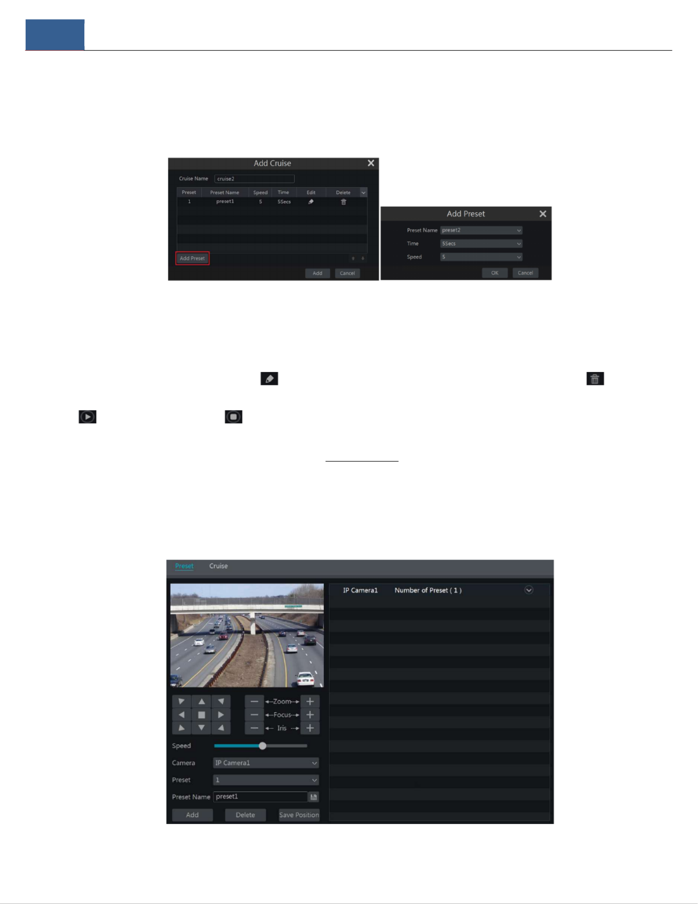
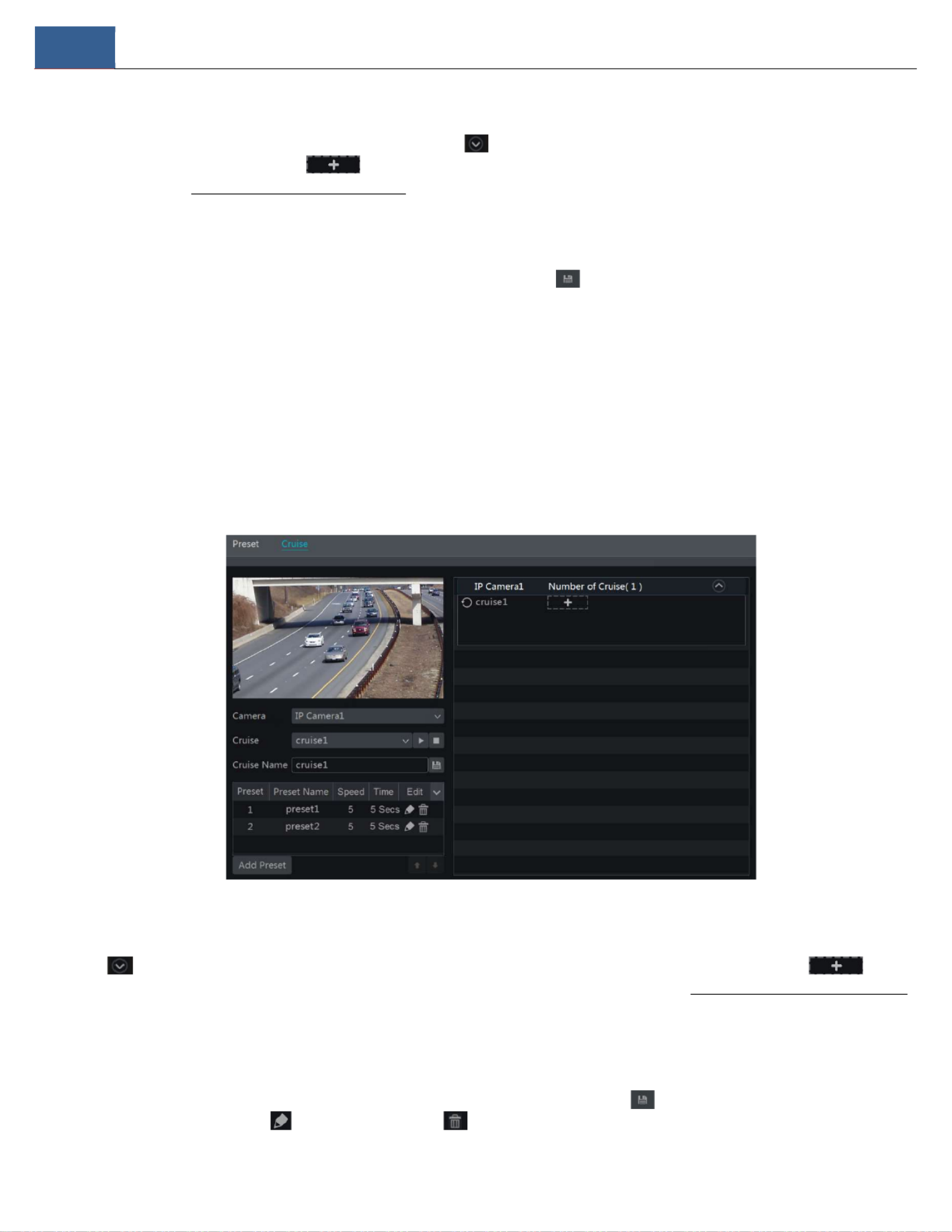
Cruise Seng
Click “Cruise” to go to cruise operaon tab and then click “Add” buon to pop up a window as shown below le. You can add up to 8 cruises for
each dome.
① Enter the cruise name in the “Add Cruise” window and then click “Add preset” to pop up the “Add Preset” window (Before adding preset to
the cruise, please add preset of the dome rst).
② In the “Add Preset” window, select the preset name, preset me and preset speed and then click “OK” buon.
③ In the “Add Cruise” window, you can click to reselect the preset, then change the preset me and speed. Click to delete the
preset. Click “Add” buon to save the cruise.
Click to start the cruise and click to stop the cruise in the cruise list of the cruise operaon tab; click “Delete” buon to delete the
selected cruise.
You can also go to cruise sengs interface for cruise sengs, see 6.3 Cruise Seng for details.
6.2 Preset Seng
Click Start Seings Camera PTZ Preset to go to the interface as shown below.
PTZ DVR User Manual
33
Add preset
Select camera and then click “Add” buon to add a preset; or click in the camera list on the right side of the interface to display the preset
informaon of the dome and then click to add a preset. The operaon of the “Add Preset” window is similar to that of the PTZ control
interface; please see 6.1 PTZ Control Interface Introducon for details.
Edit preset
Select camera and preset. You can enter the new name of the preset and then click to save the new preset name. Adjust the rotang speed,
posion, zoom, focus and iris of the preset and then click “Save Posion” to save the preset.
Delete Preset
Select camera and preset and then click “Delete” to delete the preset.
6.3 Cruise Setngs
Click Start Seings Camera PTZ Cruise to go to the interface as shown below.
Add Cruise
Click in the camera list on the right side of the interface to display the cruise informaon of the dome and then click to add
cruise. The operaons of the “Add Cruise” window is similar to that of the PTZ control interface; please see 6.1 PTZ Control Interface Introducon
for details.
Edit Cruise
Select the camera and cruise in the “Cruise” interface. Enter the new cruise name and then click to save the cruise name. Click “Add Preset”
to add preset to the cruise. Click to edit the preset. Click to delete the preset from the cruise. Click one preset in the preset list and

PTZ DVR User Manual
34
then click to move down the preset and click to move up the preset. Click to start the cruise and click to stop it.
Delete Cruise
Click in the camera list on the right side of the interface to display the cruise information of the dome and then click on the top right
corner of the cruise to delete the cruise.

Record & Disk Management DVR User Manual
35
7 Record& Disk Management
7.1 Record Conguraon
7.1.1 Mode Conguraon
Please format the HDDs before recording (refer to 7.5 Disk Management for details). Click Start Sengs Record Mode Seings to go to the
mode sengs interface. You can set the record me under the “Manual Record Sengs” and then click “Apply” to save the sengs. There are two
recording modes: auto mode and manual mode.
Auto Mode
Moon Record: Moon alarm record will be enabled when moon alarm happens.
Sensor Record:Sensor alarm record will be enabled when sensor alarm happens.
Moon Record+Sensor Record:Moon/sensor alarm record will be enabled when moon/sensor alarm happens.
Connuous Record+Moon Record:Normal record is enabled all the me; moon alarm record will be started when moon alarm happens.
Connuous Record+Sensor Record: Normal record is enabled all the me; sensor alarm record will be started when sensor alarm happens.
Connuous Record+MoonRecord+Sensor Record:Normal record is enabled all the me; moon/sensor alarm record will be enabled when
moon/sensor alarm happens.
Connuous Record+MoonRecord+Sensor Record+ Analycs Record:Normal record is enabled all the me; moon/sensor/analycs alarm record
will be enabled when moon/sensor/intelligence analycs alarm happens.
You can add more auto modes under intelligent recording. Click “Advanced” buon to pop up a window as shown below. Check the modes in the
window and then click “Add” buon to show the modes in the record mode list (in this window, the checked modes can be shown in the record
mode list while the unchecked modes cannot; you should check “ ”). Analycs Record

Record & Disk Management DVR User Manual
36
Select one auto mode to pop up the corresponding window. Set the encode, GOP, resolution, FPS, bitrate type, quality, max bitrate and audio of
each camera and then click “OK” to save the settings. Please adjust the parameters according to the actual condition.
Video Encode: the available options are H.265 and H.264 if the connected IP camera supports H.265, or the option will be H.264 only.
GOP: group of pictures.
Resolution: the higher the resolution is, the clearer the image is.
FPS: the higher the frame rate is, the more fluency the video has. However, more storage room will be taken up.
Bitrate Type: CBR (Constant bitrate) and VBR (Variable bitrate) are optional. CBR means that no matter how much change is seen in the video
scene, the compression bitrate will be kept constant. VBR means that the compression bitrate will be adjusted according to scene changes. For
example, for scenes that do not have much movement, the bitrate will be kept at a lower value. This will help to optimize network bandwidth.
Quality: When VBR is selected, you need to choose image quality. The higher the image quality you choose, the more bitrate will be required.
Max Bitrate: 32Kbps ~10240Kbps are optional.
Manual Mode
If Manual Mode is selected, you need to set the encode parameters and record schedules of each camera. See 7.2 Encode Parameters Setting and
7.3 Schedule Setting for details.
7.1.2 Advanced Conguraon
Click Start Settings Record Advanced to go to the following interface. Enable or disable “Overwrite mode” (Overwrite mode: the earliest
recorded data will be replaced by the latest when the disks are full). Set the pre-alarm record time, post-alarm record time and expiration time of
each camera and then click “Apply” to save the settings.

Record & Disk Management DVR User Manual
37
Pre-alarm Record Time: set the time to record before the intended recording begins.
Post-alarm Record Time: set the time to record after the intended recording is finished.
Expiration Time: set the expiration time for recorded video. If the set date is overdue, the recorded data will be deleted automatically.
7.2 Encode Parameters Setting
Click Start Settings Record Encode Parameters to go to the interface as shown below. Set the encode, resolution, FPS, GOP, bitrate type,
quality, max bitrate and audio of the main stream for each camera in “Event Recording Settings” and “Schedule Recording Settings” interfaces. Click
“Apply” to save the settings. You can set the record stream of each camera one by one or batch set them for all cameras.
Click Start Settings Record Stream Settings to go to “Sub-stream” interface. Set the encode, resolution, FPS, GOP, bitrate type, quality and max
bitrate of sub-stream for each camera in the interface and then click “Apply” to save the settings.

Record & Disk Management DVR User Manual
38
7.3 Schedule Setting
7.3.1 Add Schedule
Click Start Settings Record Record Schedule Edit Schedules to go to the interface as shown below. “24 7”, “24 5” and “24 2” are the default × × ×
schedules; you cannot edit or delete “24 7” while “24 5” and “24 2” can be edited and deleted. Click the schedule name to display the detailed × × ×
schedule information on the left side of the interface. The seven rows stand for the seven days in a week and each row stands for 24 hours in a day.
Blue stands for the selected time and gray stands for unselected time.
Click to add a new schedule. Refer to the picture below.

Record & Disk Management DVR User Manual
39
Set the schedule name and schedule time and then click “Add” to save the schedule. You can set day schedule or week schedule. : add button;
: delete button.
Set Day Schedule
Click and then drag the cursor on the time scale to set record time; click and then drag the cursor on the time scale to delete the
selected area.
You can manually set the record start time and end time. Click or and then click “Manual” on each day to pop up a window as shown
below. Set the start and end time in the window and then click “OK” to save the settings.
Click “All” to set all day recording; click “Reverse” to swap the selected and unselected time in a day; click “Clear All” to clear all the selected area in
a day.
Click “Copy To” to copy the schedule of the day to other days. Refer to the picture below. Check the days in the window and then click “OK” to save
the settings.

Record & Disk Management DVR User Manual
41
Set the ming record schedule of each camera. See 7.3 Schedule Seng for details.
7.4.3 Moon Based Recording
Moon Based Recording: the system will start moon-based recording when the moon object appears in the setup schedule. The setup steps are
as follows:
① Set the moon-based recording schedule of each camera. See 7.3 Schedule Sengfor details.
② Enable the moon and set the moon area of each camera. See 9.2.1 Moon Conguraon for details.
The camera will start moon-based recording once you nish the above sengs.
7.4.4 Sensor Based Recording
① Set the sensor-based recording schedule of each camera. See 7.3 Schedule Setngfor details.
② Set the NO/NC type of the sensor, enable the sensor alarm and then check and congure “Record”. See 9.1 Sensor Alarm for details.
7.4.5 Analycs Recording
① Set the analycs recording schedule of each IP camera. See 7.3 Schedule Seng for details.
② Enable the intelligence alarm detecon (object detecon, excepon, tripwire, or intrusion) and draw alert surface or warning area of each IP
camera. See Event for details.
The camera will start analycs recording once you nish the above setngs. This funcon is only available for some IPCs.
7.5 Disk
7.5.1 Disk Management
Disk Management
Click Start Sengs Disk Disk Management to go to disk management interface. You can view the DVR’s disk number and disk status and so on
in the interface. Click the “Formang” buon to format the HDD.
7.5.2 Storage Mode Conguraon
Click Start Seings Disk Storage Mode to go to the interface as shown below.

Record & Disk Management DVR User Manual
42
There are four disk groups. By using disk groups, you can correspond the camera to a disk (the recording data of the camera in the group will be
stored into the disks in the same group). ADVR with e-SATA interface supports e-SATA recording.
The added disks and cameras will be added into group one automatically. All disks and cameras in the groups can be deleted except group one
(select a disk group and then click on the top right corner of the added disk or camera to delete it from the group). The deleted disks and
cameras will be moved into group one automatically.
Each group can add the disks and cameras from other groups. Each disk and camera can only be added into one group. Select a disk group and then
click in the disk or camera row to pop up a window. Check the disks or cameras in the window and then click “Add”.
Some models may support a “Backup Group”. If your device doesn’t support this function, please skip the following instructions.
You can add the important channels into the backup group to avoid data loss.
Select “BK Group” and then click to add a disk as the backup disk. An authentication box will pop up. After entering the login username
and password, click “Format Now” to select the backup disk. The added backup disk will be formatted and this disk will be removed from the
normal group. Then add cameras to the backup group. These cameras can be added to a normal group and the backup group simultaneously.
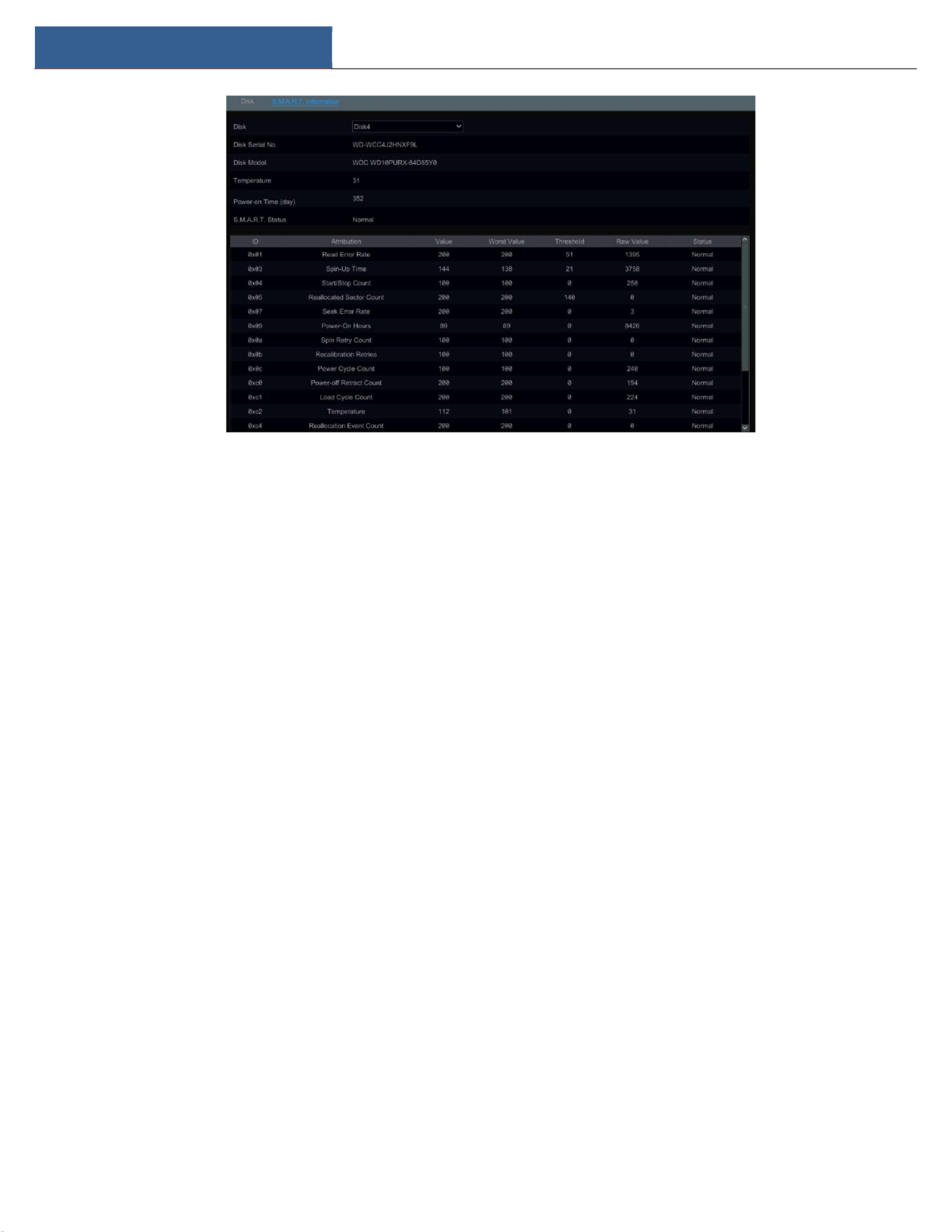
7.5.3 View Disk and S.M.A.R.T. Information
Click Start Settings Disk View Disk Information to view the HDD information; click “S.M.A.R.T. Information” to view the working status of the
HDD. Refer to the picture below.
Record & Disk Management DVR User Manual
43
Alarm Management DVR User Manual
44
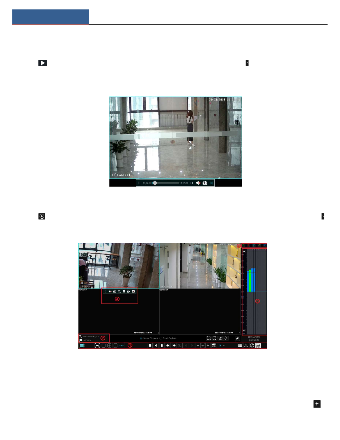
8 Playback& Backup
8.1 Instant Playback
Click on the tool bar at the bottom of the preview camera window to play back recorded video (click on the tool bar at the bottom of the
live view interface to set the default playback time). Refer to the picture below. Drag the playback progress bar to change the playback time. You
can also click the right-click menu “Instant Playback” in the camera window and then set the instant playback time to play back the record.
8.2 Playback Interface Introduction
Click on the tool bar at the bottom of the live view interface or click Start Playback to go to the playback interface as shown below (click
on the tool bar at the bottom of the live view interface to set the default playback time).
On the panel on the right you will see the channel number and the recorded data coded by color. The bar that runs across them represents the
playback time being viewed. You can move this bar around to export, highlight a section of the desired recording, click export and follow the
prompts. You can export single or multiple channels at the same time.
The added cameras will playback their records in the playback interface automatically. You can also add the playback camera manually. Click in

Alarm Management DVR User Manual
45
the playback window to pop up the “Add Camera” window. Check the cameras in the window and then click “Add” to add playback camera. The
system supports a maximum of 16 synchronous playback cameras.
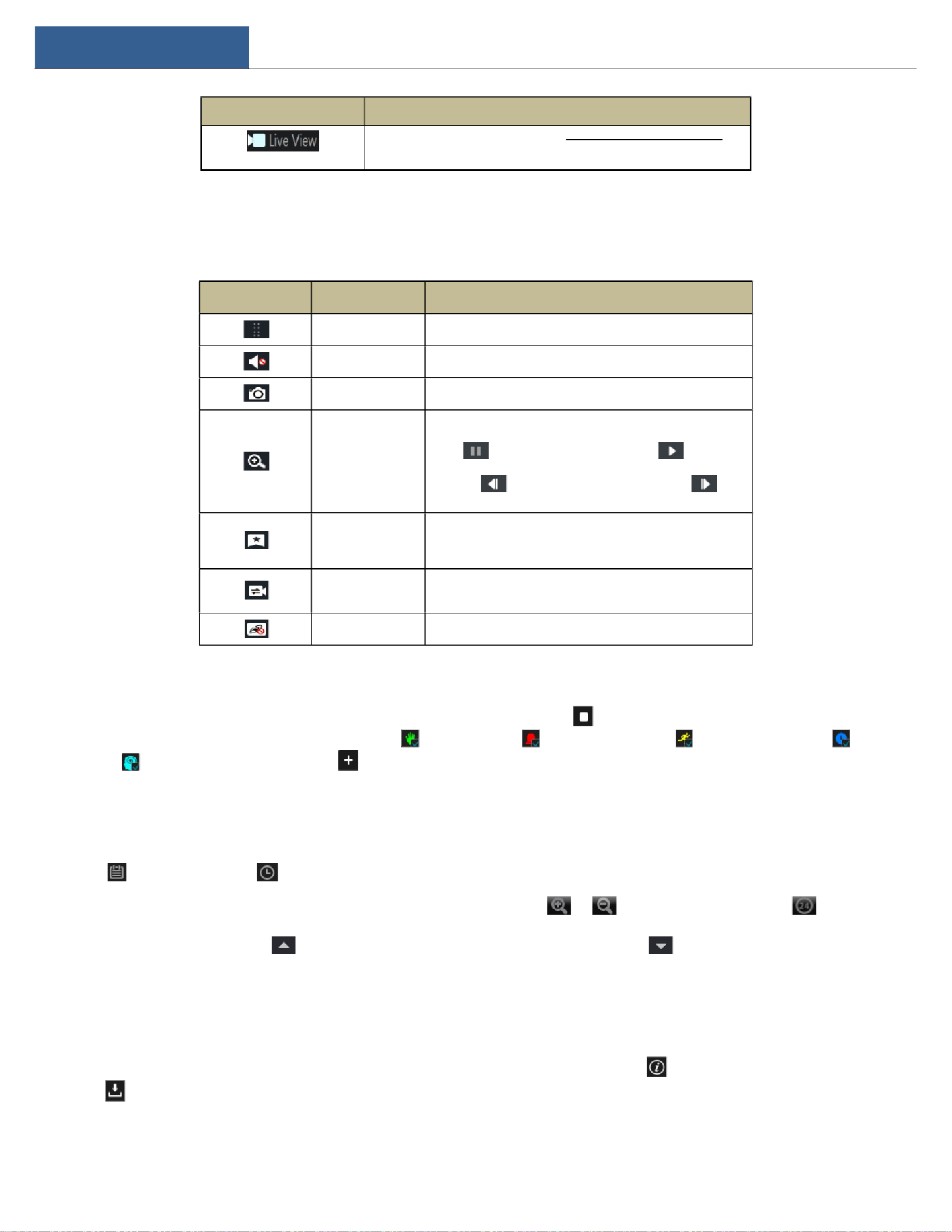
The buttons on the tool bar (area ①) at the bottom of the playback interface are described in the table below.
Button Meaning
Start button. Click to pop up area ②.
Full screen button. Click to show full screen; click it again to exit the full screen.
Screen mode button.
OSD ON button. Click to enable OSD; click again to disable OSD.
Stop button.
Rewind button. Click to play video backward.
Play button. Click to play video forward.
Pause button.
Deceleration button. Click to decrease the playing speed.
Acceleration button. Click to increase the playing speed.
Previous frame button. This works only when the forward playing is paused in single
screen mode.
Next frame button. This works only when the forward playing is paused in single screen
mode.
Click to step backward 30s and click to step forward 30s.
Click to show the water mark on the image; click to hide the water mark.
Event list/tag button. Click to view the event record of manual/schedule/sensor/ motion
and the tag information.
Backup button. Drag the mouse on the time scale to select the time periods and cameras,
and then click the button to back up the record.
Backup status button. Click it to view the backup status.
Back button. Click it to return.
Full screen motion button.
Motion button.
Draw line button. You can search all recordings of crossing this line after it’s drawn.
Draw quadrilateral. You can search all recordings this quadrilateral after it’s drawn.
Smart playback settings. Click to set smart playback.
Introduction of area ②:
Button Meaning
Click to go to record search and export interface; see 8.4 Record Search,
Playback & Backup for details.
Alarm Management DVR User Manual
46
Button Meaning
Click to go to the live view interface; see Chapter 5 Live View Introduction for
details.
Click on the playback window to show the tool bar as shown in area ③; right click on the window to show the menu list. The tool bar and menu
list are introduced in the table below.
Button Menu List Meaning
-- Move tool. Click it to move the tool bar anywhere.
Enable Audio Click to enable audio. You can listen to the camera audio by
enabling audio.
Snapshot Click to take a snapshot.
Zoom In
Click to go to the zoom in interface. The zoom in interface is
similar to that of the camera window in the live view interface.
Click to pause the record playing; click to play the
record. When the record is paused in forward playing mode, you
can click to view the previous frame and click to
view the next frame.
Add Tag
Click to add tag. You can play back the record by searching the
added tag. Click it and then enter the tag name in the popup
window. Click “Add” to add tag.
Switch Camera Click to switch the playback camera. Click it and then check the
camera in the popup window. Click “OK” to change the camera.
Close Camera Click to close the playback camera.
Introduction of area ④:
You can check the recording type as required for record playback; first you should click on the tool bar at the bottom of the interface to clear
all the playback cameras, then check the recording type ( : manual record; : sensor based record; : motion based record; : schedule
record; : analytics record; and finally click in the playback window to add camera for playback (the record time scale will show the record
data of the checked record type only after the above operations).
Introduction of the record time scale (area ⑤):
Click to set the date; click to set the time and then the playback camera will play the record from the time you set.
A tool bar will appear after moving the mouse to the record time scale. Click / to zoom the timeline; click to recover the
timeline to 24 hours ratio. Drag the timeline or slide the scroll wheel of the mouse on the time scale to show the hidden time on the top or bottom
of the timeline. You can also click to show the hidden time on the top of the timeline or click to show the hidden time on the bottom
of the timeline. Drag the slider at the bottom of the time scale to show the hidden playback cameras.
The record time scale shows different record types with different colors. The green block stands for manual recording, red block stands for
sensor-based recording, yellow block stands for motion based recording, blue block stands for schedule recording and cyan block stands for
intelligence recording. Click the record block to set the time and then the playback camera will play the recording from the time you set.
Drag the color block on the time scale to select the backup area and then right click the area or click to pop up an export information window.
Click button in the window to pop up the export window. Select the device, export path and format and then click “Export” button to start
the backup.
Alarm Management DVR User Manual
47
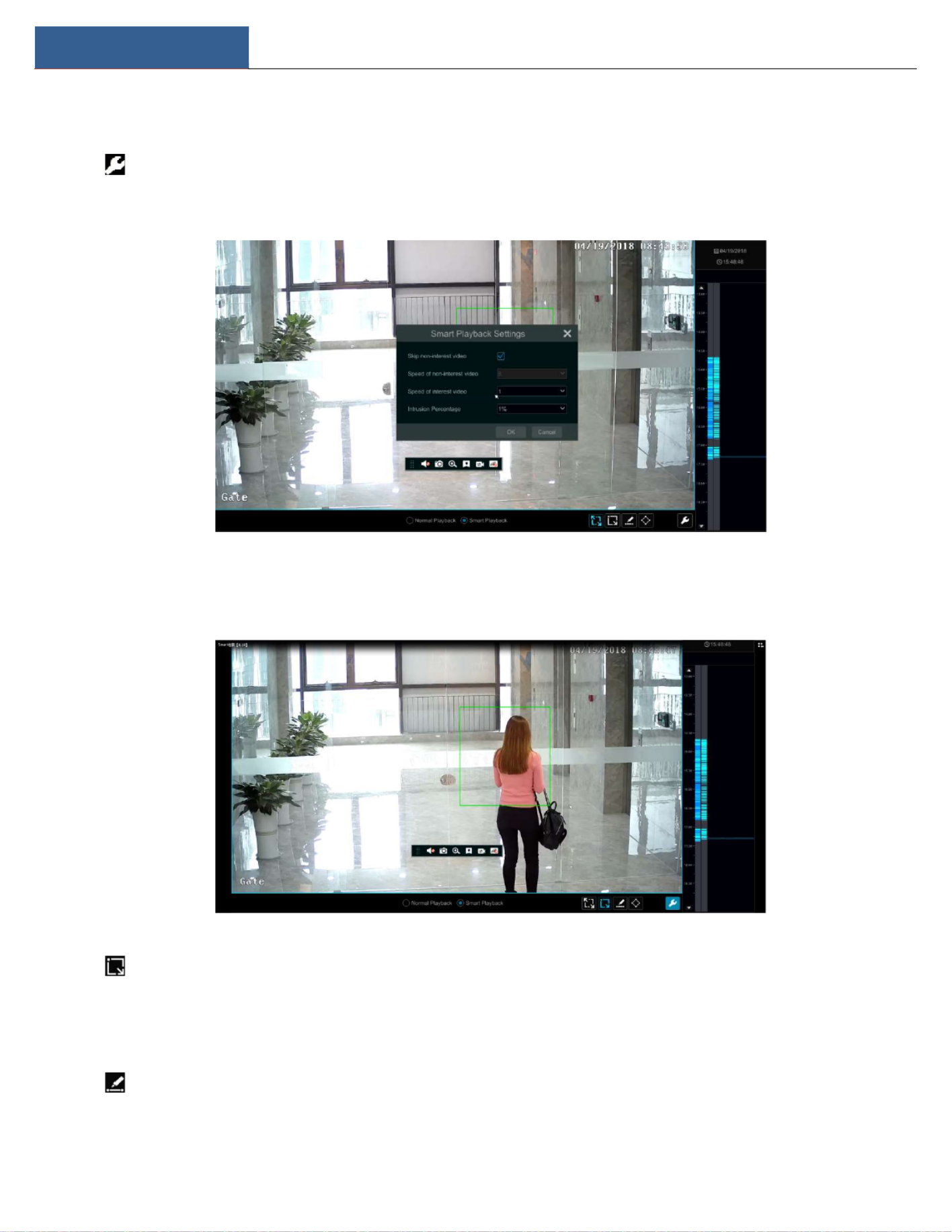
8.3 Smart Playback
Smart Playback Settings
Click to go to the following interface. Set the value of “Speed of non-interest video” (You will skip this if you select “Skip non-interest video”),
“Speed of interest video” and “Intrusion percentage”.
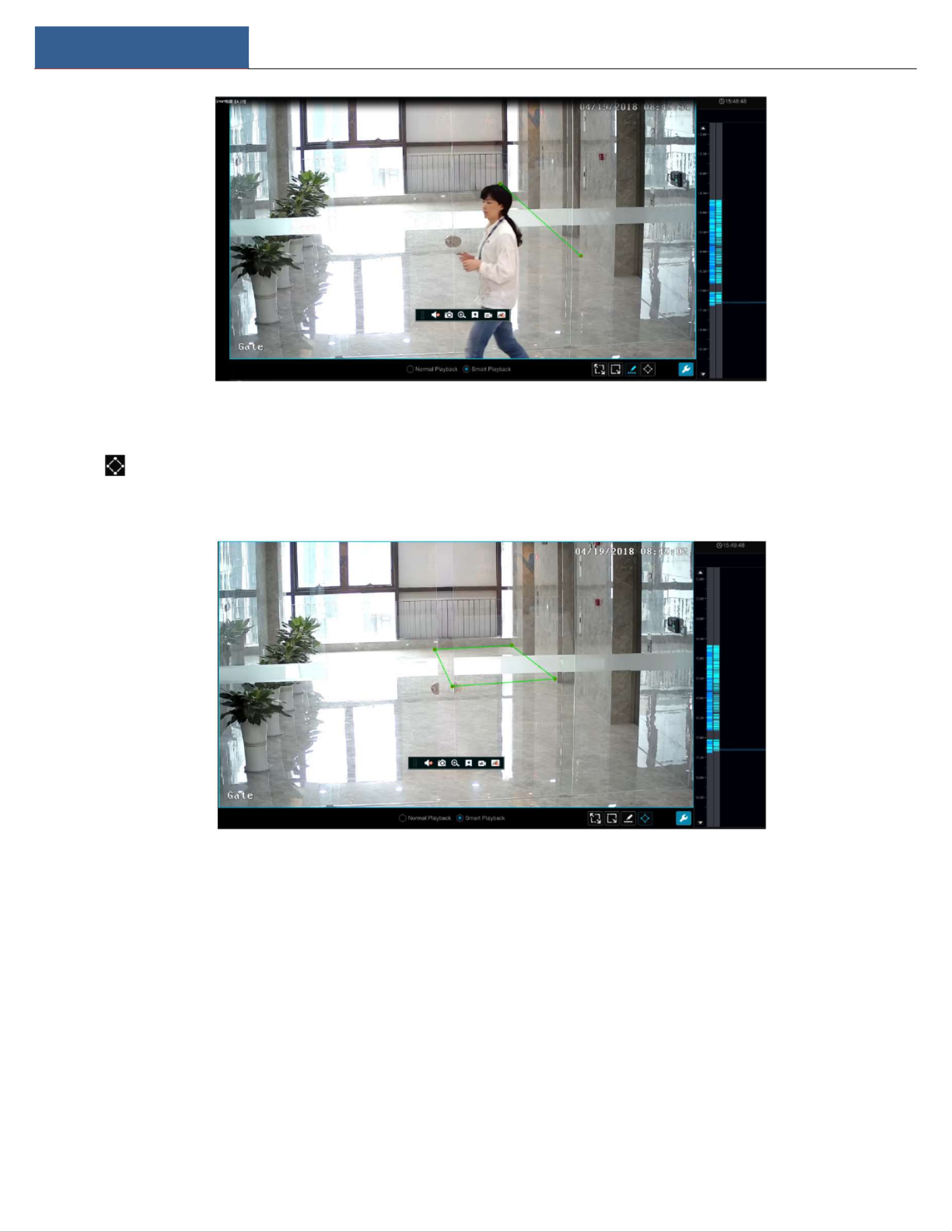
Smart Playback by Drawing Rectangle
Click and draw a rectangle in the desired area. The system will then automatically search the recordings of this area. The cyan blocks indicate
that there are intelligent recording files. Move the cursor to such a block and click to play the recording.
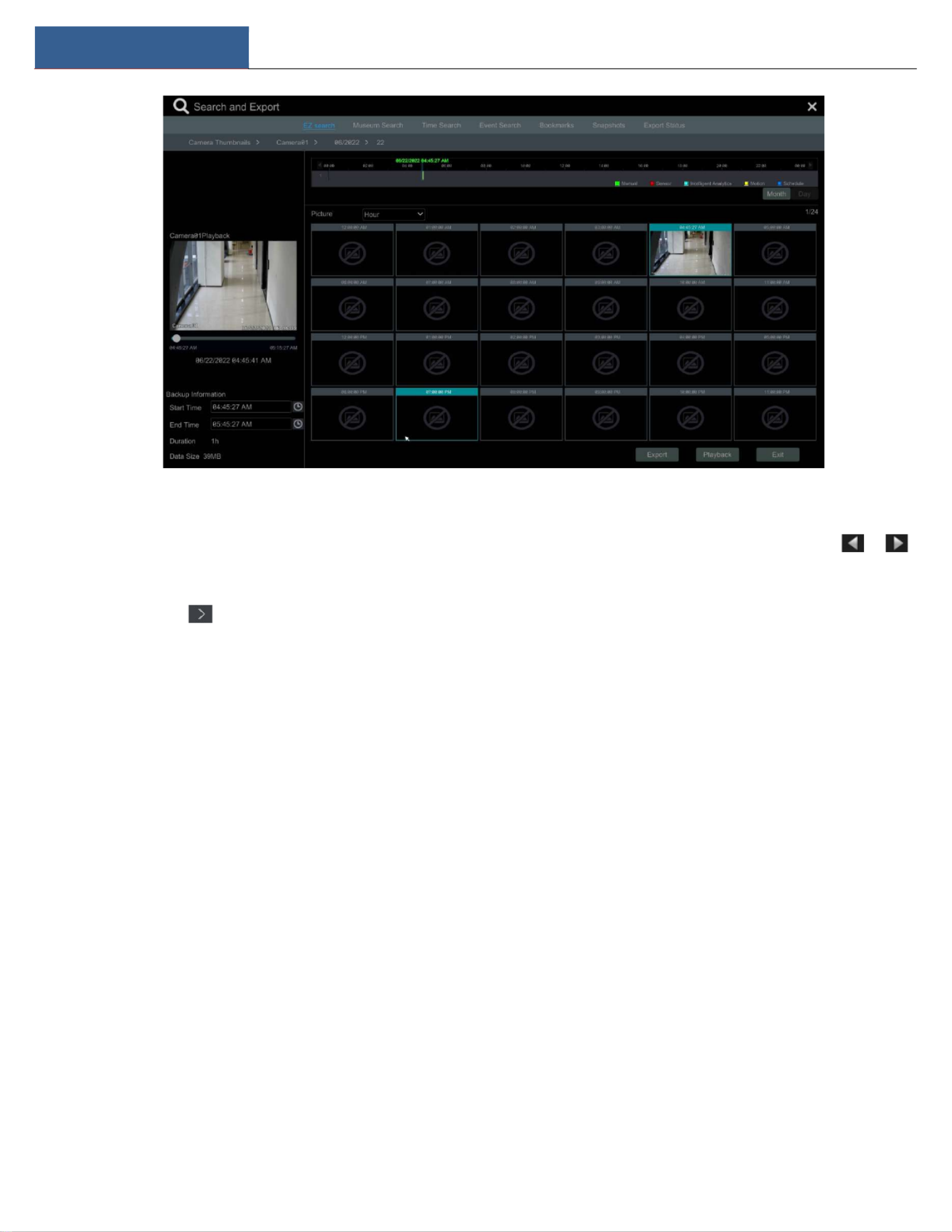
Smart Playback by Drawing Line
Click and draw a line in the desired area. The system will then automatically search the recordings where this line has been crossed. The cyan
blocks indicate that there are intelligent recording files. Move the cursor to such a block and click to play the recording.
Alarm Management DVR User Manual
48
Smart Playback by Drawing Quadrilateral
Click and draw a quadrangle in the desired area. The system will then automatically search the recordings of this area. The cyan blocks
indicate that there are intelligent recording files. Move the cursor to such block and click to play the recording.
8.4 Record Search, Playback &Export
The recording data and the captured pictures can be exported through USB (U disk or USB mobile HDD). The file system of the export devices
should be FAT32 format.
8.4.1 EZ Search 2.0
① Click Start Search and Export EZ Search to go to the “EZ Search” tab. There are two view modes: by time and by camera. In the time view
mode, a maximum of 64 camera thumbnails can be shown. If the camera thumbnail number is more than 64, the cameras will be listed directly by
their camera name, not the thumbnail. A maximum of 196 camera names can be listed. If the camera name number is more than 196, the time
view mode will be disabled and the camera view mode will be available only.

Alarm Management DVR User Manual
49
② Select one camera in the interface and then click “Open” button.
③ Click the image box to play the recording in the small playback box on the left side of the interface (the box which has image inside indicates
that the record data exist).
④ Refer to the picture below. Drag the color blocks on the time scale to select the recording data and then click “Export” button to pop up the
“Record Backup” window as shown below. Select the device name, backup format and path and then click “Export” button to start the backup.
⑤ Click the “Playback” button to play the recording in the playback interface (refer to 8.2 Playback Interface Introduction for details). Click “Exit”
to exit the interface.
Note: If you back up the record in private format, the system will back up a RPAS player to the USB
device automatically. The private format record can be played by RPAS player only.
Alarm Management DVR User Manual
50
EZ Search :
Method One: Click “Year”, “Month” or “Day” buon under the record me scale to select the me slice mode. In “Day” mode, click /
on the le/right side of the time scale to view the record of the last/next day; click “Minute” in the “Picture” opon under the me scale to select
“Minute” mode (in “Minute” mode, click the me scale to change the me of the 60 display windows) and click “Hour” to select “Hour” mode.
Method Two: Click beside “Camera Thumbnail” on the le top corner of the interface to select the me slice mode.
Method Three: Right-click the mouse on any area of the me-sliced interface to go back to the upper interface.
8.4.2 Museum Search
Click Start Search and Backup Museum Search to go to “Museum Search” tab as shown below.
Set the searching me period and you will search the channel which has the intelligence detecon record.
Check the channel and select the smart playback.
Set the backup me and select the channel to backup.

Alarm Management DVR User Manual
51
: Smart playback setngs buon. Click to set intrusion percentage.
: Full screen moon buon.
: Moon buon.
: Draw line buon. You can search the record of crossing the line aer drawing the line.
: Draw quadrilateral. You can search the record in this quadrilateral aer drawing it.
8.4.3 Time Search
① Click Start Search and Export Time Search to go to the “Time Search” tab as shown below.
② Click on the boom of the interface to add a playback camera. A maximum of 16 cameras can be added for playback. Click “Modify” on
the top right corner of the camera window to change the camera and click “Clear” to remove the camera.
③ Click the camera window to play the recording in the small playback box on the le side of the interface. You can set the date on the top le of
the interface, check the event type as required and click the me scale or click under the me scale to set the me. The camera window will
play the record according to the me and event type you set.
④ Drag the color blocks on the time scale to select the record data (or click “Set Backup Time” buon on the boom le corner of the interface
to set the backup start me and end me) and then click “Export” buon for record backup. Click “Playback” buon to play the record in the
playback interface.

Alarm Management DVR User Manual
52
8.4.4 Event Search
① Click Start Search and Export Event Search to go to “Event Search” tab as shown below.
② Check the event type in the interface as required.
③ Click to set the start me and end me on the top le of the interface.
④ Check cameras on the le side of the interface or check “All” to select all the cameras and then click to search the recording. The
searched record will be displayed in the list.
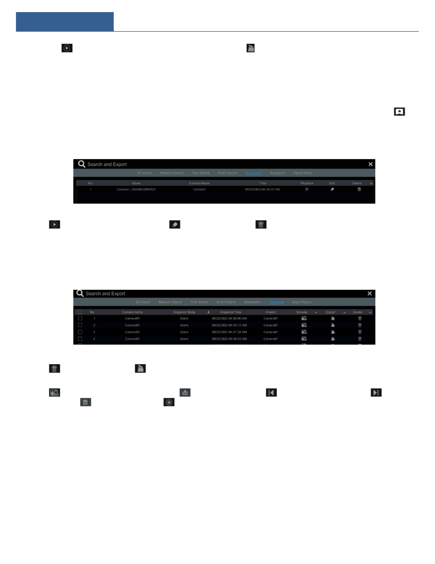
Alarm Management DVR User Manual
53
⑤ Click in the list to play back the recording in the popup window. Click to back up one recordings data or check mulple recordings
data in the list and then click “Backup” buon for recording batch backup.
⑥ Select one recordings data in the list and then click “Playback” buon to play the recording in the playback interface.
8.4.5 Bookmark Search
You can only play recordings by “Tag Search” if you have added tags. Click Start Playback to go to the playback interface and then click on
the boom of the camera window to add bookmarks when you want to mark the playback me point of the selected camera.
Click Start Search and Export Bookmarks to go to “Bookmarks” tab.
Click in the interface to play the record. Click to edit the tag name. Click to delete the tag.
8.4.6 Snapshots
Click Start Search and Export Snapshots to go to “Snapshots” tab. The system will display all the captured images automacally in the list.
Click to delete the image. Click to pop up the “Export” window. Select the device name and save path in the window and then click
“Save” buon.
Click to pop up the “View Image” window. Click to export the image. Click to view the previous image; click to view the
next image; click to delete the image; click to play all the images.
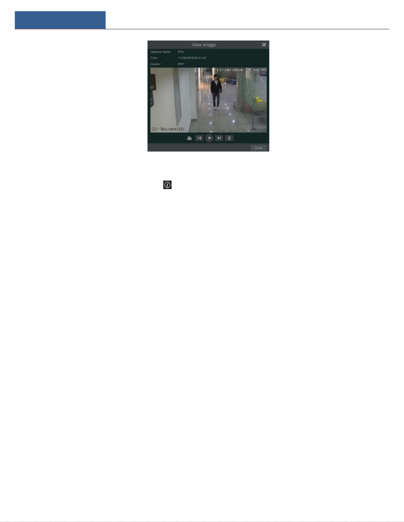
Alarm Management DVR User Manual
54
8.4.7 View Export Status
Click Start Search and Export Export Status or click on the tool bar at the boom of the playback interface to view the export status.
Product specificaties
| Merk: | Speco Technologies |
| Categorie: | Videorecorder |
| Model: | H6WHRLN |
Heb je hulp nodig?
Als je hulp nodig hebt met Speco Technologies H6WHRLN stel dan hieronder een vraag en andere gebruikers zullen je antwoorden
Handleiding Videorecorder Speco Technologies

23 Juni 2023
20 Juni 2023
17 Juni 2023
13 Juni 2023
12 Juni 2023
12 Juni 2023
10 Juni 2023
9 Juni 2023
8 Juni 2023
5 Juni 2023
Handleiding Videorecorder
- Videorecorder Bosch
- Videorecorder Philips
- Videorecorder Sony
- Videorecorder Samsung
- Videorecorder Panasonic
- Videorecorder LG
- Videorecorder Canon
- Videorecorder Daewoo
- Videorecorder Grundig
- Videorecorder JVC
- Videorecorder Motorola
- Videorecorder Medion
- Videorecorder Toshiba
- Videorecorder A.C.Ryan
- Videorecorder Abus
- Videorecorder Acti
- Videorecorder Airlive
- Videorecorder Aiwa
- Videorecorder Aristona
- Videorecorder Axis
- Videorecorder Bang Olufsen
- Videorecorder Blaupunkt
- Videorecorder D-Link
- Videorecorder Digitus
- Videorecorder Dual
- Videorecorder Elro
- Videorecorder Evga
- Videorecorder Ezviz
- Videorecorder Foscam
- Videorecorder GeoVision
- Videorecorder Grandstream
- Videorecorder Hikvision
- Videorecorder Hitachi
- Videorecorder LevelOne
- Videorecorder Linksys
- Videorecorder Lorex
- Videorecorder Magnavox
- Videorecorder Magnum
- Videorecorder Monacor
- Videorecorder Navitel
- Videorecorder Provision ISR
- Videorecorder QNAP
- Videorecorder Seagate
- Videorecorder Skytronic
- Videorecorder Sylvania
- Videorecorder Synology
- Videorecorder Technaxx
- Videorecorder Tenda
- Videorecorder TP Link
- Videorecorder Trendnet
- Videorecorder Vivotek
- Videorecorder Zoom
- Videorecorder Kunft
- Videorecorder Ubiquiti Networks
- Videorecorder Imou
- Videorecorder Tripp Lite
- Videorecorder Planet
- Videorecorder DataVideo
- Videorecorder Dahua Technology
- Videorecorder UniView
- Videorecorder Reolink
- Videorecorder Blackmagic Design
- Videorecorder Moxa
- Videorecorder Digital Watchdog
- Videorecorder AVer
- Videorecorder DirecTV
- Videorecorder Vimar
- Videorecorder Hanwha
- Videorecorder Inkovideo
- Videorecorder Pentatech
- Videorecorder Ernitec
- Videorecorder HiLook
- Videorecorder Mach Power
- Videorecorder Avigilon
- Videorecorder IDIS
- Videorecorder Milesight
Nieuwste handleidingen voor Videorecorder
2 April 2025
29 Maart 2025
12 Maart 2025
12 Maart 2025
25 Februari 2025
25 Februari 2025
13 Februari 2025
13 Februari 2025
11 Februari 2025
11 Februari 2025