Nelson SmartZone EZ 8506 Handleiding
Nelson
Besproeiingsbesturing
SmartZone EZ 8506
Lees hieronder de 📖 handleiding in het Nederlandse voor Nelson SmartZone EZ 8506 (173 pagina's) in de categorie Besproeiingsbesturing. Deze handleiding was nuttig voor 49 personen en werd door 2 gebruikers gemiddeld met 4.5 sterren beoordeeld
Pagina 1/173

SmartZone™EZ
INSTALLATION AND PROGRAMMING GUIDE
For Models:
8504
8506
8508
8512
8514
8516
8518
8522
8574
8576
8578
8582

1
THANK YOU for purchasing the SmartZoneTM EZ electronic irrigation
controller. You’ll soon discover why we’ve dubbed it the “ ”. We are EZ
confident it will be the easiest and most reliable controller you will ever use.
It’s so “EZ”, you’ll probably be able to install and program this feature-packed
controller without instructions. However, before installing and programming
the controller, we recommend you read these instructions carefully to take full
advantage of all the SmartZoneTM EZ has to offer.
If you have questions, problems or comments on your new SmartZoneTM EZ,
please call our Technical Services Department toll-free at 1-800-NELSON8.
Leaders in Turf Irrigation Since 1911
NOTE: In our efforts to continually improve and update our products, features
and specifications in this manual may change without notice.

TABLE OF CONTENTS
Features 3
Installation 4-9
Terminal Strip 5
Connecting Master Valve or Pump-Start Relay 5
Wiring the Transformer 5-6
Connecting Rain/Moisture Sensor 7
Connecting Battery & Resetting Controller 8-9
Programming the SmartZoneTM EZ 10-19
Programming Overview 10
Front Panel Layout 11-12
Set Time of Day 13
Set Current Day 13
Set Today's Date 13
Select Zones and Set Their Run Times 13-14
Set Start Times 15
Set % Water Budget 15
Scheduling 16-17
Set Water Days Scheduling Option 17
Set Odd/Even Day Scheduling Option 18
Set Interval Scheduling Option 18
Program Review 19
Turning the Controller Off 19
Advanced Features 20-21
Run A Zone Manually 20-21
Run A Program Manually 21
Run A 3 Minute Test (Syringe) 21
Technical Data/Specifications 22-24
Troubleshooting/Service 25
FCC Rules 26
Warranty 27
2

FEATURES
•Professional grade
•Easy to use dials and buttons for programming
•Large and clear LCD (Liquid Crystal Display)
•Non-volatile memory for program retention without AC power or
batteries
•3 independent programs
•3 start times per program (9 total starts)
•3 scheduling options (7 day calendar, odd/even, 1-30 day interval)
•3 test cycles (manual, cycle, 3 minute test)
•Water budgeting
•Programmable run times from 1 minute to 9 hours 59 minutes
•Exclusive Select&AdjustTM programming
•Internal transformer
•2 year warranty on materials and workmanship
3

INSTALLATION INSTRUCTIONS
NOTE: Instructions are for indoor or outdoor use.
Find a location near a 110V (220V for 8574, 8576, 8578, and 8582 models) outlet or a 110V wiring
source. Install the SmartZoneTM EZ near eye level if possible. Open the face panel by
loosening the panel locking screw and pulling the tab on the right of the front panel to swing the
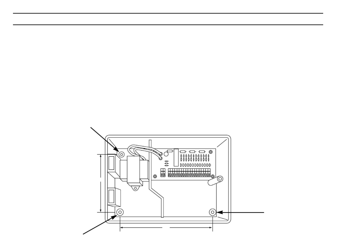
panel open on its hinges. Use the three holes in the case to mark and pre-drill pilot holes in the
wall. The left two hole guides in the SmartZoneTM EZ are vertically aligned for mounting the
controller to a stud. (See Figure 1) Insert screws through the holes in the case and screw each
into the corresponding pilot hole in the wall.
NOTE: The front panel can be removed to aid in installation by removing the ribbon
connector from the interconnect board and pulling the front panel off its hinges.
FIGURE 1
4.375"
6.875"
4

INSTALLATION INSTRUCTIONS
Terminal Strip
All zone, pump and sensor wire connections made inside the SmartZone TM EZ utilize tool-less
connectors. Press on the terminal strip lever with a pen or small screwdriver and insert the wire
into the bottom. The terminal strips in the SmartZoneTM EZ controller accept 12 AWG (4.8mm)
wire or smaller.
Connecting Master Valve or Pump-Start Relay
The SmartZoneTM EZ is equipped with a shared circuit to operate either a pump-start relay or a
master valve. Connect one wire from the pump-start relay to COM (common) on terminal strip,
the other to PMP/MV (pump/master valve) on the terminal strip. Refer to the pump-start relay
manufacturer’s instructions for specific installation details.
Wiring the Transformer*
*110 VAC in United States, Canada and Mexico; 220 VAC in Europe and Australia
NOTE: Refer to and follow local codes if different from these instructions.
CAUTION:
Disconnect 110V (220V for 8574, 8576, 8578, and 8582 models) power source
before wiring transformer. Complete all wiring and installation before connecting
the transformer to power source. This will avoid accidental shorting which could
damage the controller.
5

INSTALLATION INSTRUCTIONS
For models 8504, 8506, 8508, 8512
With front panel open to provide access to the internal transformer, bring 110V wires up through
1/2" conduit hole in the bottom of the case. (For field connection, AC wires must have an
insulation rated at 75°C minimum). Conduit should be secured to the case (follow local codes).
Attach AC wires to transformer wires using wire nuts. Also, ensure earth ground wire is attached
to green with yellow stripe ground wire. Please check local codes for the grounding requirements
in your area. Bundle wire within cable tie loop and tighten cable tie to prevent loose wiring from
touching secondary circuits.The transformer is now wired. DO NOT turn on power yet.
For models 8574, 8576, 8578, 8582
With front panel open to provide access to the internal transformer, bring 220V wires up through
1/2" conduit into the left hole in the bottom of the case. (For field connection, AC wires must have
an insulation rated at 75°C minimum). Conduit should be secured to the case (follow local codes).
Connect AC wires to connector provided and tighten screws. Observe proper polarity of wires as
you install them (ie. L1, L2 and ground). Bundle wire within tie loop and tighten cable tie to prevent
loose wiring from touching secondary circuits. The transformer is now wired. DO NOT turn on
power yet.
NOTE: Failure to ground unit properly may cause severe damage to the controller and/or
personal property and will void warranty.
For models 8514, 8516, 8518, 8522:
The transformer has been pre-wired with a 6 foot AC power cord with grounding plug. We
recommend that you do not alter this connection. Replacement of this cord must follow local
codes and in all cases the unit must be properly grounded.
6

INSTALLATION INSTRUCTIONS
Connecting Battery and Resetting Controller
Connect one 9V Alkaline battery to the battery clip and insert into the battery holder on the back of
the front panel. The battery enables the SmartZone TM EZ to be programmed without AC power
and maintains the real time clock in the event of a power outage. If a battery is not installed, the
controller will lose real time in the event of a power outage. The battery should be replaced once
a year.
CAUTION:
Use a 9V alkaline battery only. A 9V NiCad battery may leak or explode causing
personal injury or property damage.
After installing the battery, press the black reset button on the back of the front panel to reset the
controller (does not affect program(s)). To reset the controller to its default settings, press both the
black reset button and the key simultaneously. Release reset button before releasingSELECT
select key. Close the front panel, being sure not to damage wires. If wires are stiff, you may
find it helpful to pre-bend them. Tighten the panel screw to secure the front panel to the case.
Plug in the AC cord for the transformer or turn on the power source.
NOTE: Since all programs are stored in non-volatile memory, you will not lose program
settings during a power failure - even if there is no battery installed.
8

PROGRAMMING INSTRUCTIONS
After the last zone and before the first zone, a RUN TIME summation is provided. This is useful
for determining the total run time for a program. The LCD displays the letters “ALL” and a total
RUN TIME is displayed. The time displayed is a summation of all the RUN TIMES for the
selected program (100% water budget). (ex. A program has a run time of 5 minutes on zone 1; 12
minutes on zone 2; and 6 minutes on zone 4. The display at this position displays ALL and a run
time of 23 minutes).
FIGURE 5
14
Time
Current Day
Date
Manual
Semi-Auto
3 Minute TestInterval
Odd/Even
AUTO OFF
Program
Program
Mode
A C
B
Water Days
% Water
Budget
Start Times
Zone/Run Time
ODD
EVEN
INT.
S SFTHWTM
•
•
•
•
•
•
•
•
•
•
•
•
•
•
•
•
•
•
Select Adjust
®SmartZone™ EZ
A B C
M

PROGRAMMING INSTRUCTIONS
Set Start Times
A START TIME is the time of day a program will start running. The SmartZone TM EZ allows three
start times per program.
Turn the large dial to the START TIMES SELECTposition. Press to select the start time you
want to set (1, 2, or 3). Press to set the time of day the program will start. RepeatADJUST
as needed.
Set % Water Budget
% WATER BUDGET changes the duration of run times in a program by the percentage entered 5
- 200% (i.e., a 10 minute run time at 50% water budget will run 5 minutes). This feature is useful
when changes in weather occur. If it is unusually dry, you may want to extend your run time for
each zone in a program. With % Water Budget, you can change one number, and all run times in
the program are adjusted.
Turn the large dial to the % WATER BUDGET position. A % symbol will appear on the LCD to let
you know you are working on the % Water Budget amount. Press to choose theADJUST
desired percentage amount.
15

PROGRAMMING INSTRUCTIONS
If water budget is set for 110% or greater, the SmartZone TM EZ will split the run time in half to reduce
runoff. Half of the calculated run time will operate for each zone in that program, followed by the
second half of the run time for each zone.
Remember, % Water Budget is changeable by program. If you have programming in A, B, and C, you
must enter three water budget values if you want every program to be changed.
SCHEDULING
A quick note on scheduling and the SmartZone
TM
EZ …
The SmartZone TM EZ controller has three scheduling options:
• WATER DAYS, or daily, lets you choose which days of the week you want to water (i.e.,
Monday, Wednesday, Friday only).
• ODD/EVEN tells the controller to water on either the odd or even days of the month (i.e., the
controller will water on the 31 st and the 1 st when an ODD schedule is chosen).
• INTERVAL waters every X number of days (from 1 to 30 days) (i.e., water every 3 days,
water every 10 days, etc.). A value of 1 in an interval schedule means to water every day.
When using the interval option, you have the flexibility to tell the controller what day to start
the interval program on (up to 30 days out).
16

PROGRAMMING INSTRUCTIONS
NOTE: The MODE dial must be in the “Program” position to set a schedule.
When the dial is set to any of the scheduling options, the LCD will display the currently scheduled
program (default is a 1 day interval schedule with today’s date for a start date). Be sure the
PROGRAM dial is set on the program you want to change (A, B, or C) and that you want to
change the current schedule. A scheduling option is chosen after you press a button, either
SELECT or ADJUST. The old schedule is replaced with the new one. If you want the old
schedule back, it’s easy to reprogram with the following procedures.
Set Water Days Scheduling Option
Turn the large dial to the WATER DAYS scheduling option. The last scheduling option chosen for
the current program or the default 1 day interval scheduling option will appear on the LCD. Press
the button to select that day for watering or press for non-watering days.SELECT SELECT
A flashing indicator appears over the day you’re about to set. Rain drops appear over▼
selected days to water. The indicator automatically moves one day to the right after a SELECT▼
or key press. Continue selecting or deselecting the days you want the controller to water
until you have your 7 day calendar set.
NOTE: Programming a WATER DAYS schedule deletes any other schedule for the selected
program.
17

PROGRAMMING INSTRUCTIONS
Set Odd/Even Day Scheduling Option
Turn the large dial to the position. The last scheduling option chosen for the currentODD/EVEN
program or the default 1 day interval scheduling option will appear on the LCD. To set either an
odd or an even schedule press the button (a date must be set for odd/evenSELECT
watering). An arrow will appear on the LCD next to the appropriate schedule (Odd or Even). The
SELECT buttons act as toggle keys and will toggle between odd or even.
NOTE: Programming an ODD/EVEN schedule deletes any other schedule for the selected
program.
Set Interval Scheduling Option
Turn the large dial to the INTERVAL position. The last scheduling option chosen for the current
program or the default 1 day interval scheduling option appears on the LCD. Press SELECT
to set the interval days between watering (1-30). The date displayed is day one of the interval
schedule. (today’s date if one has been set). As needed, change the date for day one of the
interval schedule with (can only be set up to 30 days out).ADJUST
Repeat the above procedures for each program (A, B, or C) you require.
That’s it! Your SmartZone TM EZ is now programmed. Turn the dial to the MODE AUTO position to
run the program you entered.
NOTE: Programming an ODD/EVEN schedule deletes any other schedule for the selected
program.
PROGRAMMING INSTRUCTIONS 18

PROGRAM REVIEW
To review the current program, Turn the dial to the position and turn the largeMODE PROGRAM
dial to the setting you wish to review (i.e., turn the large dial to TIME to review the time set for the
controller). When you need to view different zones or run times (1, 2, 3), use the SELECT
buttons only.
NOTE: Since you are in the program mode, the potential exists to change the program
accidentally.
TURNING THE CONTROLLER OFF
There are instances when you’ll want to suspend watering, either for short periods (while it’s
raining if you don’t have a sensor connected), or long periods (during winter). To accommodate
this, the SmartZone TM EZ can be turned “Off”. Turn the dial to the position. ThisMODE OFF
suspends all watering operations (including manual/test procedures) from operating. The clock
continues to maintain the current time and date and your program(s) is retained until you want to
run your program(s) again. To run your program, turn the MODE AUTO dial back to the position.
NOTE: The non-volatile memory of the SmartZone TM EZ will maintain your program without
power. If a battery is not present and AC power is lost, the real time for the clock
will be lost. The time will need to be reprogrammed.
19

ADVANCED FEATURES
The SmartZone TM EZ incorporates three manual/test procedures for checking the function of the
controller or allowing you to bypass the current program to water immediately. The following
section will show you how to set up the controller to:
• run a zone manually
• run a program manually
• run a 3 minute test of every programmed zone
NOTE: All test procedures are run with the MODE dial in the AUTO position. This allows the
controller to reset to the AUTO setting after running a manual/test procedure. It also
allows you the ability to walk away from the controller after setting up a manual/test
procedure and not have to come back to reset the controller to AUTO.
NOTE: All manual/test procedures ignore the sensor connection. Therefore, you can water
utilizing one of the manual/test procedures even if the sensor has suspended your
scheduled program.
Run a Zone Manually
Turn the large dial to the MANUAL position. The default of zone 01 and 00:10 minutes will be
flashing (recall that this means you can change them). Press to select the zoneSELECT
number that you want to run. Press to set the run time for the selected zone. TheADJUST
controller will delay 10 seconds before starting the zone.
20

ADVANCED FEATURES
The SmartZone TM EZ incorporates Nelson’s ManualAdvance feature in the MANUAL
procedure. ManualAdvance allows you to cease the currently running zone and immediately
advance to any new zone you select. With the MANUAL procedure running a zone, press
SELECT to advance to a new zone. The last entered run time will be displayed. Press
ADJUST to enter a new run time for the new zone (the controller will delay 10 seconds before
starting the new zone).
Run a Program Manually
Turn the large dial to the position. The current program letter will flash. To change to aCYCLE
different program, turn the PROGRAM dial to the desired program (A, B, or C). The controller will
delay 10 seconds before starting the selected program. After running, the controller resets to the
AUTO procedure.
NOTE: CYCLE runs your current program immediately. Changes cannot be made to the
program in the CYCLE procedure.
Run a 3 Minute Test (Syringe)
Turn the large dial to the 3 MINUTE TEST position. A B C will flash on the LCD (they cannot be
changed). This is to let you know the controller will review all three programs and run a 3 minute
test on only those zones that have been programmed. We call this SmartSyringe .
This feature allows the controller to skip zones that have not been programmed. These may be
zones that are not hooked-up, hence, saving your pump (if equipped).
21

TECHNICAL DATA
1. Transformer
24 VAC internal transformer; 20 VA, .83A for zones and logic. The transformer can run a pump or
master valve and one zone valve, maximum.
2. Surge Protection
7 joule MOV across secondaries. (see Circuit Breaker below)
3. Sensor Operation
The SmartZone TM EZ is configured to operate the controller with or without a sensor. Sensors
must have normally closed connections (leads). The factory-installed jumper wire must be in
place if no sensor is used.
4. Zone Lines
The SmartZone TM EZ will operate a maximum of two (2) outputs concurrently, providing one is the
pump/master valve. Each zone output can operate one solenoid.
I inrush .52A max
I hold .40A max
22

TECHNICAL DATA
5. Temperature Range
Operating: -5 to +55 C (23 to 131 Fahrenheit)° ° ° °
Storage: -30 to +85 C (-22 to 185 Fahrenheit)° ° ° °
6. Display
7. Batteries
One 9V Alkaline battery is required. .Do not use NiCad batteries
8. Program Retention
Non-volatile memory is used to retain programs when battery and AC power are lost. The
non-volatile memory is updated when the program is changed and at 5 minute intervals.
Non-volatile memory will operate for a minimum of 5 years, worst case.
9. Case Dimensions (approx.)
6" H x 9.5" W x 3.75" D (lid is removable without tools)
23
ODD
EVEN
INT.
Su SFTHWTM
A B C
M
Time, Date, Run Time, Start Time,
% (symbol), Interval start date
Sensor suspend symbol
No AC power symbol
Current day
Program letter A, B or C
PM indicator
Year, Zone number, Start Time
number, Water Budget %,
Interval number
Water days

TECHNICAL DATA
10. Default Program
12:00 a.m. (there is no “a.m.” indicator on the LCD)
Sunday
Date is 01/01 96
No Run Times (zone 01, —:—)
No Start Times (start number 01, —:—)
100% Water Budget
Every day watering schedule (Interval = 01; Start date = today)
Mode dial is at OFF position
Program dial is on A program
3 second delay between zones (cannot be changed)
11. Circuit Breaker
An electronic poly-switch is incorporated on the interconnect PCB of the controller. This type of
circuit breaker does not require resetting or replacement by the user.
24

25
SYMPTOM POSSIBLE CAUSE SOLUTION
no output to zone, pump or • AC disconnected • check AC source, if AC is not detected
master valve by the controller, the no AC indicator
will be lit
no AC and blank display • no battery or dead battery • replace battery and press reset
LCD is blank • no AC and no battery • install battery to regain use of display,
check AC to ensure output to field
• ribbon cable is disconnected • ensure ribbon cable between the front
panel and controller board is
connected at both ends
LCD is scrambled or is missing • controller needs to be reset • press the reset button. If still
segments scrambled, press the reset button and
the select + button at the same time
(returns to factory defaults)
“M-X” appears on the LCD when • MODE dial is in program position • position the MODE dial in the AUTO
trying to run a zone manually position to run a zone manually
“C-X” appears on the LCD when • MODE dial is in program position • position the MODE dial in the AUTO
trying to CYCLE a program position to cycle a program
“S-X” appears on the LCD when • MODE dial is in program position • position the MODE dial at the AUTO
trying to run a 3 MINUTE TEST position to run the 3 Minute Test
procedure
The controller won’t run a • No programs on A, B, or C • enter a program with run times for the
3 MINUTE TEST zones you need. The 3 MINUTE TEST
only runs those zones with programmed
run times on them
Er1 is displayed on the LCD This is a communications error between the • press reset. If the error does not clear,• micro-controller and the non-volatile memory replace the board
Er2 is displayed on the LCD This is telling the user there is more than 24•
• Review your total run times on all programs
hours of run time programmed and correct - OR -
• Press reset and select + at the same
time to return to factory default settings.
REPLACEABLE PARTS
• Transformer • 6' AC cord
• Interconnect ribbon • Interconnect board
• Front panel
TROUBLESHOOTING/SERVICE

FCC RULES
This electronic irrigation controller generates and uses radio frequency energy and if not installed and used properly, that is, in
strict accordance with the manufacturer’s instructions, may cause interference to radio and television reception. It has been type
tested and found to comply with the limits for a Class B computing device in accordance with the specifications in Subpart J of
Part 15 of FCC Rules, which are designed to provide reasonable protection against such interference in a residential
installation. However, there is no guarantee that interference will not occur in a particular installation. If this controller does
cause interference to radio or television reception, which can be determined by turning the controller off and on, the user is
encouraged to try to correct the interference by one or more of the following measures:
Reorient the receiving antenna
Relocate the controller with respect to the receiver
Move the controller away from the receiver
Plug the controller into a different outlet so that the controller and receiver are on different branch circuits
If necessary, the user should consult the dealer or an experienced radio/television technician for additional suggestions. The
user may find the following booklet prepared by the Federal Communications Commission helpful:
“How to Identify and Resolve Radio-TV Interference Problems”
This booklet is available from the U.S. Government Printing Office, Washington, DC 20402. Stock No. 004-000-00345-4.
CANADIAN RADIO INTERFERENCE REGULATIONS
NOTE: This digital apparatus does not exceed the Class B limits for radio noise emissions
from digital apparatus set out in the radio interference regulations of the Canadian
Department of Communications.
26

WARRANTY
Limited Warranty
L.R. Nelson Corporation (“Nelson”) warrants all electronic products to be free of defects in material and workmanship for a period of two (2) years from the original date of purchase. In
the event of such defects, Nelson will repair or replace, at its option, the product or the defective part.
This warranty does not extend to damage to a Nelson product or part resulting from accident, misuse, alteration, neglect, abuse, improper installation or normal wear and tear, or to
exterior appearance and color. This warranty extends only to the original user of the Nelson product.
If defect arises in a Nelson product or part within the warranty period, you should contact your installing contractor, Nelson retailer, distributor, or L.R. Nelson Corporation at one of the
following locations:
One Sprinkler Lane 1961 Miraloma Ave. 3462 Maggie Blvd.
Peoria, IL 61615 Suite B Orlando, FL 32811
(309) 690-2200 Placentia, CA 92670 (407) 648-1020
Fax (309) 692-5847 (714) 993-0496 Fax (407) 648-0924
Fax (714) 993-0496
Nelson may, at its option, require that the product or part be returned to a Nelson service point or your retailer or distributor. Nelson will determine whether the claimed defect is covered
by the warranty. If coverage is found, the product will be repaired or replaced. Please allow 4 to 6 weeks for completion of repairs or replacement and return of the product or part. If a
product or part is replaced, the replacement is warranted only for the remainder of the original product or part warranty period.
This warranty gives you specific legal rights, and you may also have other rights which vary from state to state. L.R. Nelson Corporation does not authorize any person to create for it
any other obligation or liability in connection with Nelson products.
TO THE EXTEND ALLOWED BY LAW, ANY IMPLIED WARRANTY OR MERCHANTABILITY OR FITNESS FOR A PARTICULAR PURPOSE APPLICABLE TO THE NELSON
PRODUCTS IS LIMITED IN DURATION TO THE DURATION OF THESE WRITTEN WARRANTIES. NEITHER L.R. NELSON CORPORATION NOR ITS DISTRIBUTORS OR DEALERS
SHALL BE LIABLE FOR LOSS OF TIME, INCONVENIENCE, ECONOMIC LOSS, OR INCIDENTAL OR CONSEQUENTIAL DAMAGES ARISING FROM THE SALE OR DISTRIBUTION
OF NELSON PRODUCTS WHETHER FOR BREACH OF WARRANTY HEREUNDER OF FOR NEGLIGENCE OR IN TORT. Some states do not allow limitations on how long an implied
warranty will last of the exclusion or limitation on incidental or consequential damages, so the above limitations or exclusions may not apply to you.
If you have any questions concerning the warranty or its application, please write to L.R. Nelson Corporation, One Sprinkler Lane, Peoria, Illinois 61615, U.S.A. Attention: Customer
Service.
CLAIMED DEFECTIVE MERCHANDISE POLICY
Products returned to the retailer or distributor and claimed defective must be inspected by the Nelson sales representative to determine warranty compliance. If approval is granted,
products will be repaired or replaced or a credit memorandum covering the net purchase price will be issued.
27
SmartZone
™
EZ
GUÍA DE INSTALACIÓN Y PROGRAMACIÓN
Para los modelos:
8504
8506
8508
8512
8514
8516
8518
8522
8574
8576
8578
8582

1
GRACIAS por comprar el programador de riego . UstedSmartZone™ EZ
descubrirá muy pronto por qué lo llamamos (suena como "easy","EZ"
"sencillo" en inglés). Estamos seguros de que será el programador de riego
más sencillo y fiable que usted usará en su vida. Es un programador
multifunciones tan fácil de usar que es posible que usted lo pueda instalar y
programar sin leer las instrucciones. Sin embargo, le recomendamos que
antes de instalarlo y programarlo, lea este manual cuidadosamente para
aprovechar al máximo todas las ventajas que le ofrece.SmartZone™ EZ
Si tiene alguna pregunta, problema o comentario sobre su nuevo
SmartZone™ EZ, llame por favor a nuestro Departamento de Servicios
Técnicos al número de acceso gratuito 1-800-NELSON8.
Líderes en el riego de céspedes desde 1911
NOTA: Dados nuestros esfuerzos continuos de mejorar y actualizar
nuestros productos, las características y especificaciones en
este manual pueden cambiarse sin aviso previo.

2
CONTENIDO
Funciones 3
Instrucciones de instalación 4-9
Regletas de conexión 5
Conectar la válvula maestra o relevador de arranque de la bomba 5
Cableado del transformador 5-6
Conectar el sensor de lluvia y de humedad 7
Conectar la pila y reinicializar (reponer) el programador 8-9
Instrucciones de programación 10-19
Vista global 10
Diseño del panel frontal 11-12
Fijar la hora del día 13
Fijar el día actual 13
Fijar la fecha de hoy 13
Seleccionar zonas y fijar sus tiempos de ejecución 13-14
Fijar las horas de inicio 15
Fijar % del volumen de agua 15
Fijar calendarios de riego 16-17
Fijar la opción día de riego 17
Fijar la opción día impar y par 18
Fijar la opción intervalo 18
Revisión del programa 19
Para apagar el programador 19
Funciones avanzadas 20-21
Ejecución manual de una zona 20-21
Ejecución manual de un programa de riego 21
Ejecución de una prueba de tres minutos (jeringa) 21
Datos técnicos 22-24
Detección y corrección de fallas, y servicio 25
Reglas de la Comisión Federal de Comunicaciones de EE.UU. (FCC) 26
Garantía 27

3
FUNCIONES
• Clase profesional
• Teclas y botones fáciles de usar en la programación
• Pantalla de cristales líquidos (LCD, en inglés) grande y clara
• Memoria no volátil para la retención de los programas sin alimentación CA
ni pilas
• 3 programas independientes
• 3 horas de inicio por programa (9 en total)
• 3 opciones de programación (7 días calendarios, impares y pares, e
intervalo de 1 a 30 días)
• 3 ciclos de prueba (manual, ciclo, prueba de 3 minutos)
• % de volumen de agua
• Horas de operación programables desde 1 minuto hasta 9 horas 59
minutos
• Programación de Seleccionar/Ajustar (Select&Adjust) exclusiva
• Transformador interno
• Garantía de 2 años en los materiales y la mano de obra
4
INSTRUCCIONES DE INSTALACIÓN
NOTA: Estas instrucciones son válidas para uso en interiores o exteriores.
Designar un lugar cerca de un tomacorriente de 110 V (220 V para 8574, 8576, 8578 y 8582) o
una fuente de cableado de 110 V. Instalar el SmartZone™ EZ tan al nivel de la vista como sea
posible. Abrir el panel frontal aflojando el tornillo que lo asegura y tirando de la lengüeta a la
derecha del panel frontal para abrirlo sobre sus bisagras. Utilizar las tres perforaciones en la caja
para marcar y pretaladrar los agujeros para las guías de los tornillos en la pared. Los dos
agujeros guía de la izquierda en el están alineados verticalmente para montarSmartZone™ EZ
el programador en un poste. (Vea la Figura 1) Insertar los tornillos a través de las perforaciones
en la caja y ajustarlos en el orificio guía correspondiente en la pared.
NOTA: El panel frontal puede retirarse para facilitar la instalación quitando la banda de
conexión de la tarjeta de interconexiones y tirando del panel frontal fuera de sus
bisagras.
FIGURA 1
4.375"
6.875"

5
INSTRUCCIONES DE INSTALACIÓN
Regletas de conexión
Todas las conexiones de los alambres de zona, bomba y sensor hechas dentro del SmartZone TM
EZ utilizan conectores de simple encaje (sin necesidad de herramientas). Aplicar presión sobre
las palancas en la regleta de conexiones terminales con un bolígrafo o un destornillador pequeño
e insertar el alambre hasta el fondo. La regleta de conexiones terminales del programador
SmartZone™ EZ acepta alambres de 12 AWG (4,8 mm) o más pequeños.
Conectar la válvula maestra o relevador de arranque de la bomba
El SmartZone TM EZ viene equipado con un circuito compartido para operar p34-ya sea un relevador
de arranque o una válvula maestra. Conectar un alambre del relevador de arranque a la terminal
COM (común) y el otro alambre a la terminal PMP/MV (bomba/válvula maestra) en la regleta de
conexiones. Consultar el manual del fabricante del relevador de arranque para mayores detalles
sobre la instalación específica.
Cableado del transformador*
*110 V de CA en Estados Unidos, Canadá y México; 220 V de CA en Europa y Australia.
NOTA: Consulte y cíñase a los códigos locales si son diferentes de lo indicado en este
manual.
PRECAUCIÓN:
Desconecte la fuente de alimentación de 110 V (220 V para los modelos 8574, 8576,
8578 y 8582) antes de conectar el transformador. Complete todo el cableado y la
instalación antes de conectar el transformador a la alimentación. Ésto evitará
corto-circuitos accidentales que pudieran dañar el programador.

6
INSTRUCCIONES DE INSTALACIÓN
Para los modelos 8504, 8506, 8508, 8512:
Con el panel frontal abierto para tener acceso al transformador interno, subir los alambres de
110V a través de la perforación de conducto de 1/2" en la parte inferior de la caja. (Para hacer la
conexión de campo, los alambres de CA deben tener un aislante clasificado a un mínimo de
75°C). El conducto debe quedar asegurado a la caja (siga los códigos lacales). Unir los alambres
de CA a los alambres del transformador utilizando tuercas para alambre. Asimismo, asegurarse
de unir el alambre de conexión a tierra al alambre correspondiente en la terminal verde-amarilla.
Revisar por favor los codigas locales para informarse de los requistos de conexión a tierra en su
área. Enrolle el cordón dentro del lazo plástico y apriételo para prevenir que el alambrado toque
circuitos secundarios. El transformador está ahora cableado. encender todavía la almentación.No
Para los modelos 8574, 8576, 8578, 8582:
Con el panel frontal abierto para tener acceso al transformador interno, subir los alambres de
110V a través de la perforación de conducto de 1/2" en la parte inferior de la caja. Para hacer la
conexión de campo, los alambres de CA deben tener un aislante clasificado a un mínimo de 75°
C). El conducto debe quedar asegurado a la caja (siga los códigos lacales). Conecte los alambres
de corriente alterna (AC) al conector proporcionado y apriete los tornillos. Tenga cuidado de la
polaridad de los alambres cuando los instale (ej: L1, L2 y negativo). Enrolle el cordón dentro del
lazo plástico y apriételo para prevenir que el alambrado toque circuitos secundarios. El
transformador está ahora cableado. encender todavía la almentación.No
NOTA: Si la unidad no se conecta a tierra adecuadamente, se podrían causar daños graves
al programador y/o daños materiales y personales, y anular la garantía.
Para los modelos 8514, 8516, 8518 y 8522:
El transformador ha sido precableado con un cordón eléctrico de CA de 6 pies (1,8 m) con una
clavija de conexión a tierra. Le recomendamos no alterar esta conexión. El reemplazo de este
cordón debe ceñirse a los códigos locales y en todos los casos la unidad debe estar debidamente
conectada a tierra.
7
INSTRUCCIONES DE INSTALACIÓN
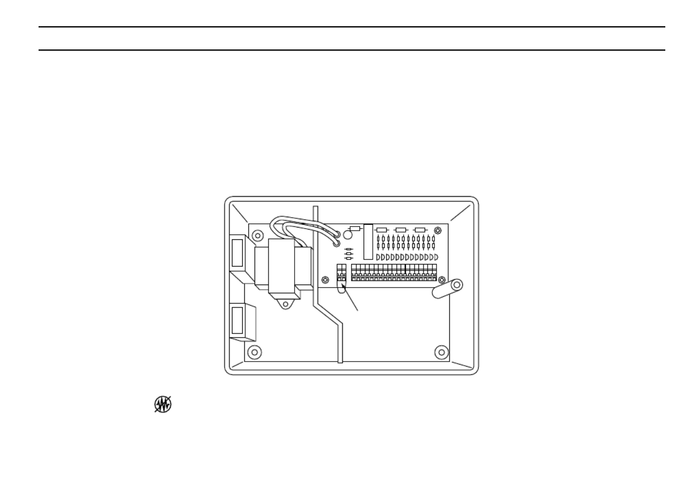
Conectar el sensor de lluvia y de humedad
El viene equipado para operar un sensor con conductores que están cerradosSmartZone™ EZ
normalmente. El puerto del sensor en el es el primer conector de simple encajeSmartZone™ EZ
en la tarjeta de interconexiones (vea la Figura 2). Para instalar un sensor, retirar del conector del
sensor el alambre de empalme instalado en fábrica en la regleta de conexiones terminales e
insertar los alambres del sensor. Consultar los detalles de instalación específicos en el manual
proporcionado por el fabricante del sensor.
FIGURA 2
Si un sensor ha suspendido el riego, el segmento indicador del sensor aparecerá así en la
pantalla LCD: .El símbolo se apagará cuando el sensor esté seco o cuando el programador
sea ajustado en uno de los modos manuales (vea las páginas 23-25). El SmartZone™ EZ
reanudará su funcionamiento de acuerdo con el programa seleccionado.
Puerto del sensor

8
INSTRUCCIONES DE INSTALACIÓN
Conectar la pila y reinicializar (reponer) el programador
Conectar una pila alcalina de 9 V a la pinza del conector e insertarla dentro del compartimiento
correspondiente atrás del panel frontal. La pila habilita al SmartZone™ EZ para ser programado
sin alimentación de CA y mantiene el reloj de tiempo real en caso de una interrupción de la
alimentación eléctrica. Si no se instala una pila, el programador perderá el tiempo real en caso de
una interrupción de la alimentación. La pila debe ser reemplazada cada año.
PRECAUCIÓN:
Utilice únicamente una pila alcalina de 9 V. Una pila NiCad de 9 V podría causar una
fuga o explotar causando lesiones personales o daños materiales.
Después de instalar la pila, oprimir el botón de reinicialización (reposición) negro en la parte de
atrás del panel frontal para reinicializar el programador (no afecta(n) el (los) programa(s)). Para
reinicializar el programador a sus ajustes por omisión (default), oprimir el botón negro de
reinicialización y la tecla a la vez. Soltar el botón de reinicializaciónSELECCIONAR
(reposición) antes de soltar la tecla Seleccionar . Cerrar el panel frontal, asegurándose de no
dañar los alambres. Si los alambres están rígidos, le podría convenir predoblarlos. Ajustar el
tornillo del panel para sujetar el panel frontal en la caja. Enchufar el cordón de CA del
transformador o encienda la fuente de alimentación.
NOTA: Dado que todos los programas se almacenan en memoria no volátil, no se perderán
los ajustes de los programas durante una falla eléctrica, aun en caso de que no se
haya instalado una pila.
Product specificaties
| Merk: | Nelson |
| Categorie: | Besproeiingsbesturing |
| Model: | SmartZone EZ 8506 |
Heb je hulp nodig?
Als je hulp nodig hebt met Nelson SmartZone EZ 8506 stel dan hieronder een vraag en andere gebruikers zullen je antwoorden
Handleiding Besproeiingsbesturing Nelson

9 Juli 2023
2 Juli 2023
25 Juni 2023
25 Juni 2023
22 Juni 2023
21 Juni 2023
21 Juni 2023
21 Juni 2023
20 Juni 2023
Handleiding Besproeiingsbesturing
- Besproeiingsbesturing Karcher
- Besproeiingsbesturing WOLF-Garten
- Besproeiingsbesturing Basetech
- Besproeiingsbesturing Blumfeldt
- Besproeiingsbesturing Brandson
- Besproeiingsbesturing Fiskars
- Besproeiingsbesturing Florabest
- Besproeiingsbesturing Gardena
- Besproeiingsbesturing Gloria
- Besproeiingsbesturing Hozelock
- Besproeiingsbesturing Hunter
- Besproeiingsbesturing Milwaukee
- Besproeiingsbesturing RAINBIRD
- Besproeiingsbesturing Toolcraft
- Besproeiingsbesturing Vonroc
- Besproeiingsbesturing Westfalia
- Besproeiingsbesturing Orbit
- Besproeiingsbesturing Clas Ohlson
- Besproeiingsbesturing Cocraft
- Besproeiingsbesturing Cotech
- Besproeiingsbesturing Fieldmann
- Besproeiingsbesturing Woox
- Besproeiingsbesturing Claber
- Besproeiingsbesturing Rain
- Besproeiingsbesturing Weathermatic
- Besproeiingsbesturing Aqua Joe
- Besproeiingsbesturing EVE
- Besproeiingsbesturing Rain Bird
- Besproeiingsbesturing Chapin
- Besproeiingsbesturing DAB
- Besproeiingsbesturing Brendz
- Besproeiingsbesturing MESTO
Nieuwste handleidingen voor Besproeiingsbesturing
1 December 2024
16 November 2024
15 November 2024
13 November 2024
29 Augustus 2024
29 Augustus 2024
17 Juni 2024
24 Mei 2024
24 Mei 2024
24 Mei 2024