JANDY JEP-R Handleiding
Lees hieronder de 📖 handleiding in het Nederlandse voor JANDY JEP-R (60 pagina's) in de categorie Pomp. Deze handleiding was nuttig voor 42 personen en werd door 2 gebruikers gemiddeld met 4.5 sterren beoordeeld
Pagina 1/60

H0412200 Rev J
ENGLISH | FRAN AIS | ESPAÑOLÇ
WARNING
FOR YOUR SAFETY - This product must be installed and serviced by a contractor who is licensed and
qualified in pool equipment by the jurisdiction in which the product will be installed where such state
or local requirements exist. The maintainer must be a professional with sufficient experience in pool
equipment installation and maintenance so that all of the instructions in this manual can be followed
exactly. Before installing this product, read and follow all warning notices and instructions that accompany
this product. Failure to follow warning notices and instructions may result in property damage, personal
injury, or death. Improper installation and/or operation will void the warranty.
Improper installation and/or operation can create unwanted electrical hazard which can
cause serious injury, property damage, or death.
ATTENTION INSTALLER - This manual contains important information about the
installation, operation and safe use of this product. This information should be given to
the owner/operator of this equipment.
INSTALLATION AND
OPERATION MANUAL
Jandy Pro Series
JEP-R
Variable-Speed Pump Digital Controller
For use with Jandy Pro Series Variable-Speed Pumps
For Indoor or Outdoor Installations

Table of Contents
DATE OF INSTALLATION
INSTALLER INFORMATION
INITIAL PRESSURE GAUGE READING (WITH CLEAN FILTER)
PUMP MODEL HORSEPOWER
FILTER MODEL SERIAL NUMBER
CONTROLLER MODEL SERIAL NUMBER
NOTES:
EQUIPMENT INFORMATION RECORD
Section 1. IMPORTANT
SAFETY INSTRUCTIONS 3 ...................
1.1 Safety Instructions 3 .............................................
1.2 Pool Pump Suction Entrapment Prevention
Guidelines 6 ..........................................................
Section 2. Installation of the
Digital Controller 7 ................................
2.1 Introduction ........................................................7
2.2 The Controller Panel 7 ..........................................
2.3 The Controller Components 7 ...............................
2.3.1 Additional materials 8 .....................................
2.4 Installation of the Backplate
onto an Electrical Box 8 ........................................
2.5 Installation of the Backplate
on a Flat Wall 8 .....................................................
2.6 Connection to Jandy® Pro Series
variable-speed Pump 8 .........................................
2.7 Variable Speed Pump Switch Settings 9 ..............
2.8 Connection to Remote Contacts 9 ........................
2.9 Remote Operation 10 .............................................
2.10 Remote Closure 4 Behavior 10 ...............................
2.11 Remote Closure 4 Application
- Booster Pump Support 10 ....................................
Section 3. User Operation of the Variable-Speed
Controller ............................................ 11
3.1 The Controller Interface .....................................11
3.2 Basic Functions .................................................11
3.3 OFF Mode ..........................................................11
3.4 RUN Mode .........................................................11
3.5 Manual Start and Stop 12 .......................................
3.6 Pump Speed Setting 12 ..........................................
3.7 Timeclock Setup and Operation.........................12
3.8 Keypad Lock 13 ......................................................
Section 4. Service Setup Options 13 .......................
4.1 Entering Service Setup 13 ......................................
4.2 Minimum and Maximum Pump Speeds 13 .............
4.3 Load Defaults 14 .....................................................
4.4 Last Fault 14 ...........................................................
4.5 Priming Speed and Duration 14 ..............................
4.6 eStar Speed 15 .......................................................
4.7 Pump Freeze Protect Operation 15 ........................
4.8 Selecting Pump Type .........................................15
4.9 Display Power Usage 15 ........................................
Section 5. User Set Up Options 16 ...........................
5.1 Setting Time-of-Day ...........................................16
5.2 Labeling Speeds 16 ................................................
5.3 General Labels 16 ..................................................
5.4 Custom Labels 16 ...................................................
5.5 Display Light Control 16 ..........................................
5.6 Language Selection 17 ...........................................
5.7 Run Duration (Speeds 3 and 4 Only) 17 .................
5.8 Password Protect 17 ...............................................
Section 6. Menu Flow Chart 18 .................................
PAGE 2
ENGLISH JEP-R Variable-Speed Pump Controller | Installation Manual

Section 1. IMPORTANT SAFETY INSTRUCTIONS
READ AND FOLLOW ALL INSTRUCTIONS
1.1 Safety Instructions
All electrical work must be performed by a licensed electrician and conform to all national, state, and local codes.
When installing and using this electrical equipment, basic safety precautions should always be followed, including the
following:
WARNING
RISK OF SUCTION ENTRAPMENT HAZARD, WHICH, IF NOT AVOIDED, CAN RESULT IN SERIOUS
INJURY OR DEATH. Do not block pump suction, as this can cause severe injury or death. Do not
use this pump for wading pools, shallow pools, or spas containing bottom drains, unless the pump is
connected to at least two (2) functioning suction outlets. Drain covers must be certified to the latest
published edition of ANSI®/ASME® A112.19.8 or its successor standard, ANSI/APSP-16.
WARNING
To reduce the risk of injury, do not permit children to use this product.
WARNING
To reduce the risk of property damage or injury, do not attempt to change the backwash (multiport, slide,
or full flow) valve position with the pump running.
WARNING
To reduce the risk of injury, do not remove the suction fittings of your spa or hot tub. Never operate a spa or hot tub if
the suction fittings are broken or missing. Never replace a suction fitting with one rated less than the flow rate marked
on the equipment assembly.
WARNING
Prolonged immersion in hot water may induce hyperthermia. Hyperthermia occurs when the internal temperature
of the body reaches a level several degrees above the normal body temperature of 98.6°F (37°C). The symptoms
of hyperthermia include dizziness, fainting, drowsiness, lethargy, and an increase in the internal temperature of
the body. The effects of hyperthermia include: 1) unawareness of impending danger; 2) failure to perceive heat;
3) failure to recognize the need to exit spa; 4) physical inability to exit spa; 5) fetal damage in pregnant women;
6) unconsciousness resulting in a danger of drowning.
WARNING
To Reduce the Risk of Injury -
a The water in a spa should never exceed 104°F (40°C). Water temperatures between 100°F (38°C) and 104°F )
(40°C) are considered safe for a healthy adult. Lower water temperatures are recommended for young children
and when spa use exceeds 10 minutes.
b) Since excessive water temperatures have a high potential for causing fetal damage during the early months of
pregnancy, pregnant or possibly pregnant women should limit spa water temperatures to 100°F (38°C).
c) Before entering a spa or hot tub, the user should measure the water temperature with an accurate thermometer
since the tolerance of water temperature-regulating devices varies.
d) The use of alcohol, drugs, or medication before or during spa or hot tub use may lead to unconsciousness with
the possibility of drowning.
e) Obese persons and persons with a history of heart disease, low or high blood pressure, circulatory system
problems, or diabetes should consult a physician before using a spa.
f) Persons using medication should consult a physician before using a spa or hot tub since some medication may
induce drowsiness while other medication may affect heart rate, blood pressure, and circulation.
PAGE 3
ENGLISH
JEP-R Variable-Speed Pump Controller | Installation Manual

WARNING
To minimize risk of severe injury or death, the filter and/or pump should not be subjected to the piping
system pressurization test.
Local codes may require the pool piping system to be subjected to a pressure test. These requirements
are generally not intended to apply to the pool equipment, such as filters or pumps.
Jandy pool equipment is pressure tested at the factory.
If, however, the WARNING cannot be followed and pressure testing of the piping system must include
the filter and/or pump, BE SURE TO COMPLY WITH THE FOLLOWING SAFETY INSTRUCTIONS:
• Check all clamps, bolts, lids, lock rings, and system accessories to ensure they are properly installed
and secured before testing.
• RELEASE ALL AIR in the system before testing.
• Water pressure for test must NOT EXCEED 35 PSI.
• Water temperature for test must NOT EXCEED 100°F (38°C).
• Limit test to 24 hours. After test, visually check system to be sure it is ready for operation.
Notice: These parameters apply to Jandy® Pro Series equipment only. For non- equipment, consult Jandy
the equipment manufacturer.
WARNING
Due to the potential risk of fire, electric shock, or injuries to persons, Jandy Pumps must be installed
in accordance with the National Electrical Code® (NEC®), all local electrical and safety codes, and the
Occupational Safety and Health Act (OSHA). Copies of the NEC may be ordered from the National Fire
Protection Association, 470 Atlantic Ave., Boston, MA 02210, or from your local government inspection
agency.
WARNING
RISK OF ELECTRIC SHOCK, FIRE, PERSONAL INJURY, OR DEATH. Connect only to a branch
circuit that is protected by a ground-fault circuit-interrupter (GFCI). Contact a qualified electrician if you
cannot verify that the circuit is protected by a GFCI. Make sure such a GFCI should be provided by
the installer and should be tested on a routine basis. To test the GFCI, push the test button. The GFCI
should interrupt power. Push the reset button. Power should be restored. If the GFCI fails to operate in
this manner, the GFCI is defective. If the GFCI interrupts power to the pump without the test button being
pushed, a ground current is flowing, indicating the possibility of electrical shock. Do not use the device.
Disconnect the device and have the problem corrected by a qualified service representative before using.
WARNING
Incorrectly installed equipment may fail, causing severe injury or property damage.
WARNING
• Do not connect system to an unregulated city water system or other external source of pressurized
water producing pressures greater than 35 PSI.
• Trapped air in the system can cause the filter lid to be blown off, which can result in death, serious
personal injury, or property damage. Be sure all air is out of the system before operating.
CAUTION
Do not start pump dry! Running the pump dry for any length of time will cause severe damage and will
void the warranty.
PAGE 4
ENGLISH JEP-R Variable-Speed Pump Controller | Installation Manual

WARNING
People with infectious diseases should not use a spa or hot tub.
To avoid injury, exercise care when entering or exiting the spa or hot tub.
Do not use drugs or alcohol before or during the use of a spa or hot tub to avoid unconsciousness and
possible drowning.
Pregnant or possibly pregnant women should consult a physician before using a spa or hot tub.
Water temperature in excess of 100°F (38°C) may be injurious to your health.
Before entering a spa or hot tub measure the water temperature with an accurate thermometer.
Do not use a spa or hot tub immediately following strenuous exercise.
Prolonged immersion in a spa or hot tub may be injurious to your health.
Do not permit any electric appliance (such as a light, telephone, radio, or television) within five (5) feet
(1.5m) of a spa or hot tub.
The use of alcohol, drugs or medication can greatly increase the risk of fatal hyperthermia in hot tubs and
spas.
Water temperature in excess of 100°F (38°C) may be hazardous to your health.
WARNING
To avoid injury ensure that you use this control system to control only packaged pool/spa heaters which have built-
in operating and high limit controls to limit water temperature for pool/spa applications. This device should not be
relied upon as a safety limit control.
Attention installer: Install to provide drainage of compartment for electrical components.
SAVE THESE INSTRUCTIONS
PAGE 5
ENGLISH
JEP-R Variable-Speed Pump Controller | Installation Manual

1.2 Pool Pump Suction Entrapment Prevention Guidelines
WARNING
SUCTION HAZARD. Can cause serious injury or death. Do not use this pump for wading pools,
shallow pools or spas containing bottom drains, unless the pump is connected to at least two
(2) functioning suction outlets.
WARNING
Pump suction is hazardous and can trap and drown or disembowel bathers. Do not use or operate
swimming pools, spa, or hot tubs if a suction outlet cover is missing, broken, or loose. The following
guidelines provide information for pump installation that minimizes the risk of injury to users of pools, spas, and hot
tubs:
• Entrapment Protection - The pump suction system must provide protection against the hazards of
suction entrapment.
• Suction Outlet Covers - All suction outlets must have correctly installed, screw-fastened covers in
place. All suction outlet (drain) assemblies and their covers must be properly maintained. Suction out-
lets (drain) assemblies and their covers must be listed/certied to the latest version of ANSI ®/ASME®
A112.19.8 or its successor standard, ANSI/APSP-16. They must be replaced if cracked, broken, or
missing.
• Number of Suction Outlets Per Pump - Provide at least two (2) hydraulically-balanced main drains,
with covers, as suction outlets for each circulating pump suction line. The centers of the main drains
(suction outlets) on any one (1) suction line must be at least three (3) feet apart, center to center. See
Figure 1.
• The system be built to include at least two (2) suction outlets (drains) connected to the pump must
whenever the pump is running. However, if two (2) main drains run into a single suction line, the sin-
gle suction line may be equipped with a valve that will shut off both main drains from the pump. The
system shall be constructed such that it shall not allow for separate or independent shutoff or isolation
of each drain. See Figure 1.
• More than one (1) pump can be connected to a single suction line as long as the requirements above
are met.
• Water Velocity - The maximum water velocity through the suction outlet assembly and its cover for
any suction outlet must not exceed the suction tting assembly and it’s cover’s maximum design ow
rate. The suction outlet (drain) assembly and its cover must comply with the latest version of ANSI/
ASME A112.19.8, the standard for Suction Fittings For Use in Swimming Pools, Wading Pools, Spas,
and Hot Tubs, or its successor standard, ANSI/APSP-16.
• If 100% of the pump’s ow comes from the main drain system, the maximum water velocity in the
pump suction hydraulic system must be six (6) feet per second or less, even if one (1) main drain
(suction outlet) is completely blocked. The ow through the remaining main drain(s) must comply with
the latest version of ANSI/ASME A112.19.8, the standard for Suction Fittings For Use in Swimming
Pools, Wading Pools, Spas, and Hot Tubs, or its successor standard, ANSI/APSP-16.
• Testing and Certication - Suction outlet assemblies and their covers must have been tested by a
nationally recognized testing laboratory and found to comply with the latest version of ANSI/ASME
A112.19.8, the standard for Suction Fittings For Use in Swimming Pools, Wading Pools, Spas, and
Hot Tubs, or its successor standard, ANSI/APSP-16.
• Fittings - Fittings restrict ow; for best efciency use fewest possible ttings (but at least two (2) suc-
tion outlets).
• Avoid ttings which could cause an air trap.
• Pool cleaner suction ttings must conform to applicable International Association of Plumbing and
Mechanical Ofcials (IAPMO) standards.
PAGE 6
ENGLISH JEP-R Variable-Speed Pump Controller | Installation Manual

Section 2.
At Least
3 Feet
Suction Outlet
(Main Drain)
Suction Outlet
(Main Drain)
No Valves between
Tee and Main Drains
Listed/Certified to latest
published edition of
ANSI®/ASME® A112.19.8
or its successor standard,
ANSI/APSP-16
Anti-entrapment
Cover/Grate or Suction
Fitting, Securely-fastened
to Main Drain Sump
Listed/Certified to latest
published edition of
ANSI®/ASME® A112.19.8
or its successor standard,
ANSI/APSP-16
Anti-entrapment
Cover/Grate or Suction
Fitting, Securely-fastened
to Main Drain Sump
Valves OK between
Pump and Tee
WARNING: Suction check valves and hydrostatic valves should not be used with this pump.
Pump
Figure 1. Number of Suction Outlets Per Pump
Installation of the
Digital Controller
2.1 Introduction
This document provides general instructions to
install and operate the JEP-R Variable-Speed Digital
Controller. The controller can be mounted to an
electrical gang box (single, double, or triple) or to a at
wall.
The instructions have been written with safety as the
priority, and must be followed exactly. Read through the
instructions completely before starting the procedure.
2.2 The Controller Panel
The controller panel provides both timed and manual
speed controls for the Variable Speed Pumps.
Four (4) speeds are directly available on the panel,
while four (4) additional speeds may be accessed via the
MENU key.
LCD Display
Preset Speed
Buttons
Menu Button
LED Lights Up/Down
Arrow Keys
2 3 4
PRESS SPEED OR MENU
12:00AM PUMP IS OFF
MENU
eStar Button
Figure 2. JEP-R Controller Panel
The up and down keys are used to adjust the pump
speed. The speed is saved as it is adjusted. No further
action is required to save the new speed setting after
adjustment. The selected speed can be saved and
assigned to one of the speed buttons.
As shown in Figure 2, preset speed "" is assigned to
the "eStar" feature. Hence, it is intended to be assigned
an energy-ef cient ltration speed, as determined by the
installer.
1
External Brackets
For Wall Mounting
2
3
4
Figure 3. Controller Components
2.3 The Controller Components
The controller assembly contains the following
components. See "Figure 3. Controller Components":
1. Controller
2. Mounting Gasket
3. Backplate
4. Six (6) Screws
PAGE 7
ENGLISH
JEP-R Variable-Speed Pump Controller | Installation Manual

NOTE The controller uses a four-wire RS-485 interface
to communicate with the ePump.
5. Unplug the RS-485 connector from the pump.
6. Attach the four (4) wires in the RS-485 cable
to the RS-485 connector. Make sure the colors
match the positions on the connector. See "Figure
4. Wiring the Controller to the Variable Speed
Pump"
7. Connect the RS-485 connector back into the
pump.
8. Set the DIP switch settings for the pump controller
with the 1 and 2 in the ON position and 3 and 4
in the OFF position. See "Figure 4. Wiring the
Controller to the Variable Speed Pump".
9. Turn on all switches and the main breaker feeding
power to the pump.
10. Verify the operation of the controller. If
the controller displays FAULT PUMP NOT
CONNECTED, re-check the wiring and the DIP
switch address setting on the pump.
BLACK
YELLOW
RED
GREEN
RS485 4 3 2 1
RED
BLACK
YELL OW
GREEN
REMOTE CONTRO L
5 4 3 2 1
INPUT 2
INPUT 3
INPUT 4
COMMON
INPUT 1
4-Position
DIP Switch
Variable-Speed
Pump Motor
Controller
(Rear View)
RS485
Cable
4321
BLACK
YELLOW
RED
GREEN
Figure 4. Wiring the Controller to the Variable Speed
Pump
2.7 Variable Speed Pump Switch Settings
For the ePump™, the VS-FHP2.0 pump and the
VSPHP27, the 4-position or 5-position dip switch is
located at the rear of the pump, as shown in "Figure 4.
Wiring the Controller to the Variable Speed Pump"
This dip switch serves two functions, it determines what
type of control will be used with the pump and it selects
the pump address. The SW 1 (switch 1) and SW 2 are
turned ON if the pump is to be controlled by a JEP-R
controller or OFF if the pump is to be controlled by the
AquaLink® RS, AquaLink PDA or AquaLink Z4. See
"Table 1. DIP Switch Settings".
2.8 Connection to Remote Contacts
The controller allows speeds "" through "4" to
operate via remote contact closures (switch or relay).
Speed "4" operates differently than the other three. See
"2.10 Remote Closure 4 Behavior".
1. Turn off all switches and the main breaker that
supplies power to the variable-speed pump.
WARNING
ELECTRICAL SHOCK HAZARD
Turn off all switches and the main breaker in
the ePump electrical circuit before starting the
procedure. Failure to comply may cause a shock
hazard resulting in severe personal injury or death.
2. Connect one side of the remote contact closure
to the COMMON terminal on J3 REMOTE
CONTROL connector of the controller. See
"Figure 5. Connect to Remote Contacts"
PAGE 9
JEP-R Variable-Speed Pump Controller
| Installation Manual ENGLISH

Pump Function Pump
Address
DIP Switch Setting
1 2 3 4 5
VS-FHP 1.0
Factory Default N/A ON ON OFF OFF ON
JEP-R N/A ON ON OFF OFF ON
AquaLink® RS
AquaLink PDA
PUMP 1 OFF OFF OFF OFF ON
PUMP 2 OFF OFF ON OFF ON
PUMP 3 OFF OFF OFF ON ON
PUMP 4 OFF OFF ON ON ON
ePump,™
VS PlusHP, and
VS-FHP2.0
Factory Default N/A OFF OFF OFF OFF N/A
JEP-R N/A ON ON OFF OFF N/A
AquaLink RS
AquaLink PDA
PUMP 1 OFF OFF OFF OFF N/A
PUMP 2 OFF OFF ON OFF N/A
PUMP 3 OFF OFF OFF ON N/A
PUMP 4 OFF OFF ON ON N/A
Table 1. DIP Switch Settings
3. Connect the other side of the remote contact
closure to INPUT 1, INPUT 2, INPUT 3, or
INPUT 4 terminal on J3 REMOTE CONTROL
connector of the controller, depending on which
speed is to be controlled.
4. Turn on all switches and the main breaker feeding
power to the variable-speed pump.
5. Verify the operation of the contact closures. If
the correct speed is activated when the closure
is activated, the variable-speed pump starts, and
the message REMOTE ENABLED appears on the
controller display.
NOTE When starting the pump via a remote closure,
the pump will rst run at the priming speed for
the priming duration, as set by the installer.
2.9 Remote Operation
Speeds activated via remote closures always override
speeds that have been activated manually or via an
internal timer program. When the pump is activated
via a remote closure, the keypad is disabled and the
message REMOTE ENABLED appears on the display.
234
MENU
REMOTE ENABLED
10:00AM RPM:1200
The controller will remain in this state until the contact
is opened. When more than one (1) contact closure
occurs, the highest speed will take priority.
RS485
4 3 2 1
RED
BLACK
YELLOW
GREEN
REMOTE CONTROL
5 4 3 2 1
INPUT 2
INPUT 3
INPUT 4
COMMON
INPUT 1
J3
Remote Contact
Closure
input
common
Figure 5. Connect to Remote Contacts
2.10 Remote Closure 4 Behavior
The behavior of speed "4" differs from manual operation
when operated via a remote contact closure. As during
manual operation, the turn-on time of remote closure
4 is immediate, and occurs at the same time as contact
closure. The turn-off time, however, is delayed by 30
minutes.
In other words, when remote closure 4 is de-activated,
the variable-speed pump will continue to run for 30
minutes, after which time the controller will turn off
the variable-speed pump. The delay may be manually
interrupted by pressing any speed key.
2.11 Remote Closure 4 Application -
Booster Pump Support
The behavior of remote closure 4 may be used to allow
an external timeclock tted with a 20-minute “reman’s
switch” (e.g., Intermatic P/N 156T4042A) to properly
control the variable-speed pump in conjunction with a
booster pump.
NOTE Pump models JEP1.5, JEP2.0 allow for
alternate remote closure, or auxiliary load
options. Please see the pumps installation/
owner's manual for more information.
Connection for Booster Pump Support:
1. Turn off all switches and the main breaker that
supplies power to the variable-speed pump.
PAGE 10
JEP-R Variable-Speed Pump Controller | Installation Manual
ENGLISH

WARNING
ELECTRICAL SHOCK HAZARD
Turn off all switches and the main breaker in the
ePump™ electrical circuit before starting the
procedure. Failure to comply may cause a shock
hazard resulting in severe personal injury or death.
2. Install the normally-closed reman’s switch
to the timeclock assembly. (See timeclock
manufacturer’s instructions for details.)
3. Connect the main timeclock contacts to the
booster pump power input per the booster pump
installation manual.
4. Connect one side of the reman’s switch to
the Controller at J3 REMOTE CONTROL,
COMMON.
5. Connect the other side of the reman’s switch to the
controller at J3 REMOTE CONTROL, INPUT 4.
6. Set the timeclock to the desired on/off times.
7. Turn on all switches and the main breaker feeding
power to the variable-speed pump.
8. If the installation is working properly, the
reman’s switch will open 20 minutes before
the booster pump shuts down, the variable-speed
pump will continue to run for 30 minutes, and the
Controller will display PUMP WILL REMAIN ON
FOR XX:XX XX:XX, where is the time remaining
until variable-speed pump shutdown.
Section 3. User Operation of
the Variable-Speed
Controller
The variable-speed controller contains an advanced
microcontroller that provides a simple yet sophisticated
interface to operate your variable-speed pump for
maximum efciency and enjoyment of your pool.
The controller allows operation of the variable-speed
pump in three ways: Manually, from built-in timers, and
remotely via contact closures.
3.1 The Controller Interface
The controller interface panel provides both timed and
manual speed controls for the variable-speed pump.
Four (4) speeds are directly available on the panel, while
four additional speed presets may be accessed via the
MENU key.
The up and down keys are used to adjust the pump
speed. Speed is saved as it is adjusted. No further
action is required to save the new speed setting after
adjustment.
As shown below, preset speed "" is assigned to the
eStar feature. Hence, it is intended to be assigned an
energy-efcient ltration speed, as determined by the
installer.
3.2 Basic Functions
The controller has two (2) operational modes: User
Mode and Setup Mode.
User Mode
In the User Mode, the controller provides access to
pump control options including:
• Manual start and stop of pump
• Pump speed setting
• Timeclock setup and operation
Setup Mode
The Setup Mode allows the user to congure the
controller. Setup options include:
• Time-of-day setting
• Labeling of pump speeds
• Display light control
• Language selection
• Run duration
3.3 OFF Mode
When the pump is off, the controller displays
PRESS SPEED OR MENU/00:00 PUMP IS OFF, where
00:00 is the time-of-day clock.
234
PRESS SPEED OR MENU
12:00AM PUMP IS OFF
MENU
3.4 RUN Mode
When the pump is running, the controller displays
N:LABEL/00:00 RPM:XXXX, where n:label is the
number and label of the selected speed, 00:00 is the
time-of-day clock, and xxxx is the pump speed.
2:SPEED 2
10:00AM RPM: 1200
2 3 4
MENU
PAGE 11
JEP-R Variable-Speed Pump Controller | Installation Manual ENGLISH

3.5 Manual Start and Stop
Up to eight (8) speeds may be started from the
controller. Manual operation of speeds "eStar" through
"4" differs from manual operation of speeds "5" through
"8".
NOTE When starting the pump, the pump will rst run
at the priming speed for the priming duration, as
set by the installer.
Speeds eStar through 4
To start the pump manually running at speeds
"eStar" through "4", press button "" through "4"
corresponding to the desired speed. The associated LED
will light red and the controller enters the RUN mode.
234
MENU
2:SPEED 2
10:00AM RPM: 1200
To stop the pump, press the button again. The associated
LED will extinguish and the pump and controller will
return to the OFF mode.
Speeds 5 through 8
To start the pump manually at speeds "5" through
"8", press the MENU button. The controller displays
SELECT PRESET/N:LABEL, where n:label is the
number and label of the last selected speed "5" through
"8".
Using the arrow keys, select the desired speed to
activate, and then press MENU RUN to enter mode,
starting the pump running at the selected speed.
2 3 4
SELECT PRESET
5:SPEED 5
MENU
To stop the pump, press . To exit without starting MENU
the pump, press any button "" through "4".
3.6 Pump Speed Setting
With the exception of preset "", each speed may be
adjusted while the pump is running in that speed mode.
Preset "" is reserved for the eStar function, and its
speed is set by the installer.
To adjust the pump speed, the controller must be in the
RUN RUN mode. While in mode, the controller displays
the pump speed. Adjust the speed by pressing the up or
down arrow keys. The speed is saved by the controller
and will remain until changed again.
NOTE Pump speed is adjustable only within a certain
range. The minimum and maximum limits of the
range are set by the installer.
NOTE When used with a solar heat system, set speed
to at least 3000 RPM and potentially up to 3450
RPM, based on the pump's head required to
push the water up a minimum of 12-15 feet.
2:SPEED 2
10:00AM RPM: 1400
3.7 Timeclock Setup and Operation
NOTE The controller has a non-replaceable battery back-up
that keeps time, programs, and speed settings when power is
disconnected and should never require replacement.
The controller allows the user to create timed pump
programs on pump speeds (presets) "" and "2". The
two timers operate independently of each other, and may
overlap in time if desired.
Timeclock Setup
Start the desired speed, "" or "2". Press MENU. The
controller enters the Timeclock setup mode. Using the
arrow keys, select ON TIME MENU and press . Set the
desired pump turn-on time using the arrow keys and
press MENU OFF TIME. The time is stored. Select using
the arrow keys and press MENU. Set the desired pump
turn-off time using the arrow keys and press MENU. The
time is stored.
2:SPEED 2 TIMECLOCK
ON TIME
Using the arrow keys, select . Select TIMECLOCK
ENABLE using the arrow keys. The program is now
enabled to run. Press the speed button ("" or "2") to
return to the RUN mode.
PAGE 12
JEP-R Variable-Speed Pump Controller | Installation Manual
ENGLISH

2:SPEED 2 TIMECLOCK
ENABLE
Timeclock Operation
When the pump is stopped, the associated green LED
will illuminate, indicating a timeclock program is
enabled for that speed. If the pump has been turned on
by the timeclock, the red LED will illuminate and a
timeclock icon will show in the lower left hand corner
of the display
If two (2) timed programs overlap, the program with the
faster speed will take priority and run to completion. If
the earlier-starting program is still active, it will resume
operation.
The program off times never change, i.e., they are not
‘pushed-out’ in time when programs overlap. Timeclock
programs may be prematurely stopped by stopping
the pump manually from the keypad. This override is
active until the program start time is reached again, at
which time the timed program will start the pump as
programmed.
NOTE When starting the pump via a timed program,
the pump will rst run at the priming speed for
the priming duration, as set by the installer.
If a program overlap occurs, the pump will
immediately start at the program speed without
priming rst.
Manually Overriding a Timer Program
Timeclock programs may be prematurely stopped by
pressing the active speed key. This override is active
until the program start time is reached again, i.e., for 24
hours, at which time the timed program will start the
pump as programmed.
2 3 4
PRESS SPEED OR MENU
12:00AM PUMP IS OFF
MENU
Timer Overriding a Manual On
If the pump is started manually at a speed that has been
programmed with a timer, the pump will be stopped
by the timeclock at the programmed off time. A clock
icon appears on the display when the timer has assumed
control of the off time.
3.8 Keypad Lock
Press and hold both arrow keys for ve (5) seconds to
lock the keypad. To disable the keypad lock, repeat the
procedure while the keypad is locked.
234
MENU
KEYPAD LOCKED
12:00AM PUMP IS OFF
Section 4. Service Setup
Options
The service setup menu allows the installer to set
various operating parameters, view fault history, and
restore factory defaults.
Parameters that may be modied and set in the service
setup menu include:
• Priming speed and duration.
• Minimum and maximum pump speeds.
• "" eStar speed.
• Pump Freeze Protect operation.
4.1 Entering Service Setup
NOTE The controller must be in the OFF mode before
entering the user setup mode. While in setup
mode the controller will return back to the OFF
mode after one (1) minute since the last key
press.
To enter the service setup menu, press and hold , MENU
then press and hold the "" and speed "4" keys. Hold
all three (3) keys down for ve (5) seconds. To exit,
press any speed button.
234
MENU
PRESS SPEED OR MENU
12:00AM PUMP IS OFF
4.2 Minimum and Maximum Pump
Speeds
These speeds are considered global settings across the
entire controller, and create the range of allowable speed
that may be sent to the variable-speed pump.
PAGE 13
JEP-R Variable-Speed Pump Controller | Installation Manual ENGLISH

To set the minimum speed, from the service setup menu,
select SET MIN LIMIT using the arrow keys. Press
MENU. Using the arrow keys, set the minimum speed to
the desired value. Press MENU to accept and store.
2 3 4
SET MIN LIMIT
RPM: 600
MENU
To set the maximum speed, from the service setup
menu, select SET MAX LIMIT using the arrow keys.
Press MENU. Using the arrow keys, set the maximum
speed to the desired value. Press MENU to accept and
store.
2 3 4
SET MAX LIMIT
RPM: 3450
MENU
4.3 Load Defaults
To restore factory default settings to the controller, from
the service setup menu, select LOAD DEFAULTS. Press
MENU YES MENU. Using the arrow keys, select . Press
to restore factory default settings.
2 3 4
LOAD DEFAULTS
YES
MENU
Default Speeds
eStar 1750 RPM
Speed 2 - 8 2750 RPM
Priming Speed 2750 RPM
Other Defaults
Freeze Protect Duration 30 min
Priming Duration 3 min
4.4 Last Fault
This feature shows on the top display line, the most
recent unique fault message and on the bottom display
line, the second-to-last unique fault message. If there
is no entry for a fault, the display will show “*---------
-------*” on the corresponding line. To select last fault,
from the service setup menu select LAST FAULT. Press
MENU.
NOTE The fault messages are stored in non-volatile
memory, and remain even with no power. To
clear the fault history, press either arrow key.
2 3 4
SELECT SERVICE SETUP
LAST FAULT
MENU
4.5 Priming Speed and Duration
The controller will command the variable-speed pump
to operate at the priming speed for the priming duration
specied (except during timer program overlaps or
follow-on commands where the pump is not stopped
before changing speeds). From the service setup menu,
select PRIMING MENU using the arrow keys. Press .
2 3 4
PRIMING DURATION
MIN: 3
MENU
To set priming speed, select using PRIMING SPEED
the arrow keys. Press MENU. Using the arrow keys, set
the priming speed to the desired value. Press MENU to
accept and store.
2 3 4
PRIMING SPEED
RPM: 3450
MENU
PAGE 14
JEP-R Variable-Speed Pump Controller | Installation Manual
ENGLISH
To set priming duration, select PRIMING DURATION
using the arrow keys. Press MENU. Using the arrow
keys, set the priming speed to the desired value in
minutes from one (1) to ve (5) minutes. Press MENU to
accept and store.
2 3 4
PRIMING DURATION
MIN: 3
MENU
4.6 eStar Speed
The "" speed is intended to be used as an energy-
efcient setting that can be easily called-up by
activating the eStar preset speed from the keypad or
remote closure. After this speed has been determined
by the installer, the eStar speed may be set as follows:
From the service setup menu, select SET ESTAR
SPEED MENU. Press . Using the arrow keys, set the
speed to the desired value. Press MENU to accept and
store.
2 3 4
1:eSTAR
RPM:1250
MENU
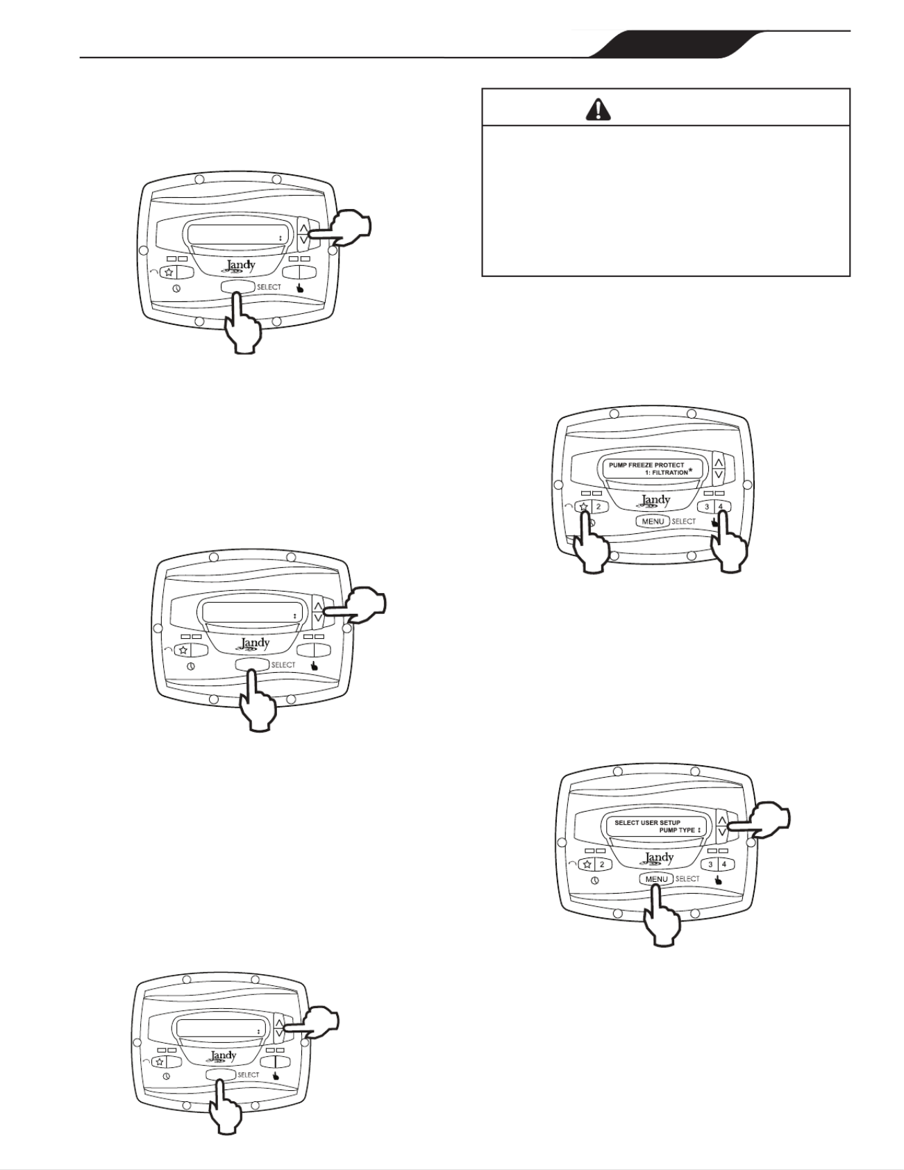
4.7 Pump Freeze Protect Operation
When enabled to do so, the controller monitors the
temperature inside the pump and will activate the
variable-speed pump at the eStar speed when the
temperature approaches freezing. The run duration of
the pump freeze protect operation is adjustable from 30
minutes to 8 hours, or may be disabled completely.
To set the pump freeze protect operation, from the
service setup menu select PUMP FREEZE PROTECT.
Press MENU. Using the arrow keys, set the duration to
the desired value. To disable pump freeze protect, set the
duration to 0:00. Press MENU to accept and store.
2 3 4
PUMP FREEZE PROTECT
1:05
MENU
WARNING
Freeze protection is intended to protect equipment and
plumbing for short periods of freezing only. It does this
by activating the filtration pump and circulating the water
to prevent freeze inside equipment or plumbing. Freeze
protection does not guarantee that equipment will not be
damaged by extended periods of freezing temperatures
or power outages. In these conditions, the pool and spa
should be shut down completely (e.g. drained of water
and closed for the winter) until warmer weather exists.
The pump freeze protect run time may be interrupted by
pressing a speed key, as follows:
Pressing the key "" once overrides the pump freeze
protect run time, pressing it twice turns off the pump.
Pressing other speed keys will override the pump freeze
protect run time and activate the selected preset speed.
4.8 Selecting Pump Type
The controller may be used to operate various types of
pumps. It is important to select the correct pump type at
this menu item to ensure proper controller operation.
From the setup menu, select PUMP TYPE. Press the
MENU button to display the currently selected pump
type. Using the arrow keys, choose the pump type that
matches the type of the installed pump. Refer to the
pump manual for information regarding the pump type.
4.9 Display Power Usage
The controller can alternately display the variable-speed
pump power usage while the pump is in operation and
the controller is in Run Mode.
To enable the power display feature, from the service
setup menu select DISPLAY POWER USAGE. Press
MENU YES to select. Using the arrow keys, select . Press
MENU to accept and store.
PAGE 15
JEP-R Variable-Speed Pump Controller | Installation Manual ENGLISH

To disable the power display feature, from the service
setup menu select DISPLAY POWER USAGE. Press
MENU NO to select. Using the arrow keys, select . Press
MENU to accept and store.
Section 5. User Set Up Options
NOTE The controller must be in the OFF mode before
entering the user setup mode. While in setup
mode the controller will return back to the OFF
mode after one (1) minute since the last key
press.
When in setup mode, speed keys "" through "4" are
used as ‘escape’ or exit keys while navigating the setup
menu.
To enter the setup mode, press and hold the MENU
button for ve (5) seconds. The controller displays
SELECT USER SETUP. Using the arrow keys, select
the desired setup item to change.
5.1 Setting Time-of-Day
From the Setup menu, select . Press the SET TIME
MENU button to display the currently-set time. Using
the arrow keys, adjust to the desired time. Press MENU
to save your setting.
5.2 Labeling Speeds
The controller comes from the factory with pre-
programmed labels or names for the preset speeds. The
labels may be changed as desired to suit your particular
installation.
Two (2) types of labels are provided by the controller:
• General Labels - selected from a list
• Custom Labels - created by the user
From the setup menu, scroll to LABEL SPEED
and press MENU. The SELECT SPEED screen
is displayed. Press the MENU button to display the
currently selected speed. Using the arrow keys, choose
the speed to be changed. Press MENU to select. The
controller displays SELECT LABEL TYPE. Select
GENERAL CUSTOM or as desired using the arrow keys.
SELECT USER SETUP
LABEL SPEED
5.3 General Labels
Using the arrow keys, select a general label from the list
to assign to the speed. Press MENU to assign the label to
the speed.
LABEL SPEED
FILTRATION
5.4 Custom Labels
In the custom label mode, the controller displays a
ashing cursor at the character position to be changed.
Using the arrow keys, change the character as desired.
Press MENU to accept the change and advance to the
next character position. Press any speed key ""
through "4" to return to the previous cursor position.
LABEL SPEED
1:PRESET 1
Continue this procedure until the end of the label is
reached. The new label is saved when MENU is pressed
at the last character position.
5.5 Display Light Control
The controller’s display is equipped with a backlight to
aid viewing in low light conditions.
PAGE 16
JEP-R Variable-Speed Pump Controller | Installation Manual
ENGLISH

From the setup menu, select DISPLAY LIGHT. Press
MENU. Using the arrow keys, select the desired
operating mode for the display backlight:
LIGHT OFF: Turn off display backlight.
LIGHT ON: Turn on display backlight.
2 MIN TIMEOUT: Turn on display backlight, with
automatic turn-off after two (2) minutes since the last
key press.
5.6 Language Selection
From the setup menu, select using the LANGUAGE
arrow keys. Press MENU. Using the arrow keys, select
the desired language. Press MENU to save the selection.
5.7 Run Duration (Speeds 3 and 4 Only)
Speeds "3" and "4" may be programmed to run for a
specied duration after being manually started. This run
duration is programmable from 30 minutes to eight (8)
hours, in increments of 30 minutes. A setting of 0:00
disables the run duration feature, allowing the speed to
run indenitely.
From the setup menu, select RUN DURATION. Press
MENU. Using the arrow keys, select the speed to be
programmed. Press MENU. Set the desired run duration
for the speed using the arrow keys. Press MENU to
accept.
5.8 Password Protect
Entry into the may be restricted USER SETUP MENU
by the setting of a four-digit password.
NOTE: There is a 10-minute delay period from the
last key press to the password becoming active. This
allows additional, protected operations to be performed
temporarily after setting the password.
From the setup menu, select PASSWORD PROTECT
and press the key.MENU
The menu will verify if the user wishes to set a
password. Using the arrow keys, select then press YES
the key.MENU
Using the arrow keys, select a value for each password
digit. Press the key to set each digit.MENU
When the last password digit is set, the password is
stored and the controller displays *PASSWORD
ACCEPTED* OFF and returns to the mode.
SELECT USER SETUP
PASSWORD PROTECT
Changing a Password
From the setup menu, select SET PASSWORD and
press the key. The controller displays MENU CHANGE
PASSWORD? CHANGE Using the arrow keys, select
and press the key.MENU
The current password is displayed. Using the arrow
keys, select a value for each password digit. Press the
MENU key to set each digit. When the last password
digit is set, the password is stored and the controller
displays *PASSWORD ACCEPTED* and returns to
the mode.OFF
CHANGE PASSWORD?
CHANGE
Clearing A Password
From the setup menu, select SET PASSWORD and
press the key. The controller displays MENU CHANGE
PASSWORD? CLEAR Using the arrow keys, select
and press the key. The password is cleared and MENU
the controller returns to the mode.OFF
PAGE 17
JEP-R Variable-Speed Pump Controller | Installation Manual ENGLISH

Section 6. Menu Flow Chart
[OFF]
TI CLOCKME [D LE]ISAB
SET OFF TIM E
[8:00 AM]
ENABLE
SET ON METI
[12:00 AM]
SET SPEE D
[2750 RPM]
SET SPEE D
[2750 RPM]
SPEED 5- 8 SET SPEE D
[2750 RPM]
USE
[1, 3]
[1, 3]
[1, 4]
[5]
[D LE]ISAB
ENABLE
TI CLOCKME
SET OFF TIM E
[8:00 AM]
SET ON METI
[12:00 AM]
MENU MENU
MENU
MENU MENU
MENU
2
3 4
N SOTE
Default parameters are shown in [ ].
1. Accessed directly by front panel button.
2. Occurs at Run Screen.
3. Timeclock features a essed via MENU button while cc
eStar or speed 2 is running.
4. MENU button has no effect when running.
5. Accessed via MENU button when pump is stopped.
6. Press and hold MENU button for five (5) seconds to enter
User Setup menu.
7. Is not affected when “LOAD DEFAULTS” is executed.
8. Key that is pressed to wake up display is also acted
upon.
9. Press and hold MENU first, then eStar and 4, and hold all
three for five (5) seconds to enter Service Setup menu.
10. Setting not saved in non-volatile memory; reset to “NO”
after execution.
11. Minimum operating speed is 1050 RPM for Jandy Pro
Series SVRS-equipped pumps.
12. Minimum priming speed is 1500 RPM for Jandy Pro Series
SVRS-equipped pumps.
PAGE 18
JEP-R Variable-Speed Pump Controller | Installation Manual
ENGLISH

Zodiac Pool Systems, Inc.
2620 Commerce Way, Vista, CA 92081
1.800.822.7933 | www.ZodiacPoolSystems.com
©2017 Zodiac Pool Systems, Inc. ZODIAC® is a registered trademark of Zodiac International,
S.A.S.U., used under license. All trademarks referenced herein are the property of their respective
owners.
H0412200 Rev J
Zodiac Pool Systems Canada, Inc.
2115 South Service Road West, Unit 3 Oakville, ON L6L 5W2
1-888-647-4004 | www.ZodiacPoolSystems.ca

Controlador digital JEP-R
Bomba de velocidad variable
ADVERTENCIA
H0412200 Rev J
PARA SU SEGURIDAD - Este producto debe ser instalado y mantenido por un contratista con la licencia
y la capacitación necesarias para trabajar con equipos para piscinas otorgadas por la jurisdicción donde
se instalará el producto en caso de que existan tales requisitos estatales o locales. La persona que realice
la instalación o el mantenimiento debe ser un profesional con experiencia suficiente en la instalación
y el mantenimiento de equipos para piscinas de tal manera que pueda seguir al pie de la letra todas
las instrucciones de este manual. Antes de instalar este producto, lea y siga todas las instrucciones y
preste atención a las advertencias en el manual adjunto. No prestar la debida atención a las advertencias
y las instrucciones puede ocasionar daños a la propiedad, lesiones personales e incluso la muerte. La
instalación y/o la operación incorrectas serán causa de anulación de la garantía.
La instalación y la operación incorrectas pueden crear un riesgo eléctrico imprevisto que puede ocasionar
lesiones graves, daños a la propiedad e incluso la muerte.
MANUAL DE INSTALACIÓN
Y OPERACIÓN
ENGLISH | FRANÇAIS | ESPAÑOL
Para usar con las bomba de velocidad variable Jandy Pro Series
Para instalaciones en interiores o exteriores

Índice
Sección 1. INSTRUCCIONES
DE SEGURIDAD IMPORTANTES 23 ......
1.1 Instrucciones de seguridad 23 ...............................
1.2 Pautas de prevención de atrapamiento por
succión de la bomba de la piscina 26 ....................
Sección 2. Instalación del controlador digital 27 ...
2.1 Introducción ......................................................27
2.2 El panel del controlador 27 ....................................
2.3 Los componentes del controlador 27 .....................
2.3.1 Materiales adicionales 28 ................................
2.4 Instalación de la placa posterior
en un gabinete eléctrico 28 ....................................
2.5 Instalación de la placa posterior
en una pared plana 28 ...........................................
2.6 Conexión de la bomba
de velocidad variable 28 .........................................
2.7 Ajustes del interruptor de la bomba
de velocidad variable 29 ........................................
2.8 Conexión a los contactos remotos 29 ....................
2.9 Operación remota 30 .............................................
2.10 Comportamiento del cierre remoto 4 30 ................
2.11 Aplicación del cierre remoto 4 - Soporte de la
bomba de reforzador 30 ........................................
Sección 3. Operación del usuario del controlador de
velocidad variable ............................... 31
3.1 La interfaz del controlador 31 ................................
3.2 Funciones básicas 31 ............................................
3.3 Modo OFF 31 .........................................................
3.4 Modo RUN (funcionamiento) 31 ............................
3.5 Arranque y detención manual 32 ...........................
3.6 Ajuste de velocidad de la bomba 32 ......................
3.7 Ajuste y operación del reloj 32 ...............................
3.8 Bloqueo del teclado 33 ..........................................
Sección 4. Opciones de conguración
de servicio 33 ..........................................
4.1 Ingresoalaconguracióndeservicio ..............34
4.2 Velocidades mínima y máxima
de la bomba 34 ......................................................
4.3 Cargar ajustes predeterminados 34 ......................
4.4 Última falla 34 ........................................................
4.5 Velocidad y duración del cebado 35 ......................
4.6 Velocidad eStar 35 .................................................
4.7 Operación de protección
contra congelamiento de la bomba 35 ...................
4.8 Selección del tipo de bomba 36 .............................
4.9 Mostrar uso de energía 36 .....................................
Sección 5. Opciones de conguración
del usuario 36 .........................................
5.1 Ajuste de la hora 37 ...............................................
5.2 Etiquetar velocidades 37 .......................................
5.3 Etiquetas generales 37 ..........................................
5.4 Etiquetas personalizadas 37 ..................................
5.5 Control de luz de la pantalla 37 .............................
5.6 Selección de idioma 38 ..........................................
5.7 Duración de funcionamiento
(solo velocidades 3 y 4) 38 ....................................
5.8 Protección con contraseña 38 ...............................
Sección 6. Diagrama de ujo del menú .............. 39
FECHA DE INSTALACIÓN
INFORMACIÓN DEL INSTALADOR
LECTURA INICIAL DEL MEDIDOR DE PRESIÓN (CON FILTRO LIMPIO)
MODELO DE LA BOMBA CABALLOS DE FUERZA
MODELO DEL FILTRO NÚMERO DE SERIE
MODELO DEL CONTROLADOR NÚMERO DE SERIE
NOTAS:
REGISTRO DE INFORMACIÓN DEL EQUIPO
PÁGINA 22 ESPAÑOL
Manual de instalación | Controlador de la bomba de velocidad variable JEP-R

ADVERTENCIA
Para minimizar el riesgo de muerte o lesiones graves, el filtro y/o la bomba no deben someterse a la
prueba de presurización del sistema de tuberías.
Las normas locales pueden requerir que el sistema de tuberías de la piscina sea sometido a una prueba de presión.
Por lo general, estos requisitos no deben aplicarse a los equipos de la piscina, tales como filtros y bombas.
Los equipos de piscina Jandy se prueban por presión en la fábrica.
Sin embargo, si la ADVERTENCIA no se puede seguir y las pruebas de presión del sistema de tuberías deben incluir
el filtro y/o la bomba, ASEGÚRESE DE CUMPLIR CON LAS SIGUIENTES INSTRUCCIONES DE SEGURIDAD:
• Verifique todas las abrazaderas, tornillos, tapas, anillos de bloqueo y los accesorios del sistema para
asegurarse de que estén correctamente instalados y asegurados antes de la prueba.
• LIBERE TODO EL AIRE en el sistema antes de la prueba.
• La presión del agua para la prueba NO PUEDE EXCEDER 35 PSI.
• La temperatura del agua para la prueba NO PUEDE EXCEDER 100 °F (38 °C).
• Limite la prueba a 24 horas. Después de la prueba, verifique visualmente el sistema para asegurarse
de que esté listo para funcionar.
Aviso: Estos parámetros se aplican solamente a los equipos Jandy ® Pro Series. Para equipos de otras
marcas, consulte al fabricante del equipo correspondiente.
ADVERTENCIA
Debido al riesgo potencial de incendio, choque eléctrico o lesiones a las personas, las bombas Jandy
se deben instalar de acuerdo con el National Electrical Code ® (NEC®), todos los códigos eléctricos y de
seguridad locales, y la Ley de Seguridad y Salud Ocupacional de EEUU (OSHA). Pueden solicitarse
copias del código NEC a la National Fire Protection Association, con dirección 470 Atlantic Ave., Boston,
MA 02210, o a su agencia gubernamental de inspección.
ADVERTENCIA
RIESGO DE DESCARGA ELÉCTRICA, INCENDIO, LESIONES PERSONALES O MUERTE. Conectar
solamente a una rama del circuito que esté protegida por un interruptor de circuito por falla a tierra
(GFCI). Contacte a un electricista autorizado si no puede verificar que el circuito está protegido por un
GFCI. Asegúrese de que el instalador proporcione un GFCI y que sea probado de manera rutinaria.
Para probar el GFCI, presione el botón de prueba. El GFCI debe interrumpir la energía. Presione
el botón Reset. Se debe restablecer la energía. Si el GFCI no funciona de esta forma, significa que
está defectuoso. Si el GFCI interrumpe la energía hacia la bomba sin presionar el botón de prueba,
quiere decir que la corriente de tierra está circulando sin problemas, lo que indica la posibilidad de una
descarga eléctrica. No utilice el dispositivo. Desconecte el dispositivo y solicite a un representante de
servicio calificado que solucione el problema antes de utilizarlo.
ADVERTENCIA
Los equipos instalados incorrectamente pueden fallar y causar lesiones graves o daños materiales.
ADVERTENCIA
• No conecte el sistema a una red de agua no regulada de la ciudad o a otra fuente externa de agua
presurizada que produzca presiones mayores a 35 PSI.
• Arrancar la bomba cuando hay aire comprimido en el sistema puede hacer que salte la tapa del
filtro, lo que puede causar serias lesiones e incluso la muerte o daño a la propiedad. Antes de operar
asegúrese de que todo el aire del sistema haya salido.
PRECAUCIÓN
¡No arranque la bomba en seco! El funcionamiento de la bomba en seco puede causar daños graves y
dejará nula la garantía.
PÁGINA 24 ESPAÑOL
Manual de instalación | Controlador de la bomba de velocidad variable JEP-R

ADVERTENCIA
Personas con enfermedades infecciosas no deben utilizar el spa ni la tina de hidromasaje.
Para evitar lesiones, tenga cuidado al entrar o salir del spa o de la tina de hidromasaje.
No consuma drogas ni alcohol antes o durante el uso del spa o la tina de hidromasaje para evitar la
pérdida del conocimiento y (posiblemente) ahogarse.
La mujer embarazada o que sospeche estar embarazada debe consultar al médico antes de utilizar el
spa o la tina de hidromasaje.
Temperaturas del agua por encima de 100 °F (38 °C) pueden ser perjudiciales para la salud.
Antes de entrar al spa o la tina de hidrom asaje mida la temperatura del agua con un termómetro fiable.
No utilice el spa ni la tina de hidromasaje inmediatamente después de haber hecho ejercicios vigorosos.
La inmersión prolongada en el spa o la tina de hidromasaje puede ser perjudicial para su salud.
No acepte la instalación de artefactos eléctricos (como luz, teléfono, radio o televisión) dentro de los
cinco (5) pies (1.5m) del spa
o la tina de hidromasaje.
El uso de alcohol, drogas o medicamentos puede aumentar considerablemente el riesgo de hipertermia
fatal en tinas de hidromasaje y spas.
Las temperaturas mayores a los 100 °F (38 °C) pueden ser perjudiciales para la salud.
ADVERTENCIA
Para evitar lesiones asegúrese de que esté utilizando este sistema de control para controlar únicamente los calentadores
de piscina/spa suministrados, los cuales tienen controles operativos y de límite alto incorporados para limitar la temperatura
delaguaenusosdepiscina/spa.Nosedebeconarenestedispositivocomouncontroldelímiteseguro.
Atención instalador:Instaleelequipodemaneraqueelcompartimientotengasucientedrenajeparalos
componentes eléctricos.
GUARDE ESTAS INSTRUCCIONES
PÁGINA 25
ESPAÑOL
Manual de instalación | Controlador de la bomba de velocidad variable JEP-R

1.2 Pautas de prevención de atrapamiento por succión de la bomba de la piscina
ADVERTENCIA
PELIGRO DE SUCCIÓN. Puede causar lesiones graves o la muerte. No use esta
bomba en piscinas para niños, piscinas de poca profundidad o spas con
drenajes en el fondo, a menos que la bomba esté conectada a por lo menos dos
(2) bocas de succión funcionales.
ADVERTENCIA
La succión de la bomba es peligrosa y puede atrapar, ahogar y eviscerar a los bañistas. No
utilizar ni operar las piscinas, o tinas de hidromasaje si alguna de las tapas de la boca de
succión está ausente, rota o suelta. Las siguientes indicaciones proporcionan información para la
instalación de la bomba minimizando el riesgo de lesiones para los usuarios de piscinas, spas y tinas de
hidromasaje:
Protección contra atrapamiento - El sistema de succión de la bomba debe proporcionar protección
contra los peligros de atrapamiento por succión.
Tapas de las bocas de succión - Todas las bocas de succión deben tener tapas instaladas
correctamente y atornilladas en su lugar. Debe hacérsele mantenimiento adecuado a todas las tapas de
las bocas de succión (drenaje). Deben ser sustituidas si están agrietadas, rotas o ausentes. Las tapas
de drenaje deben cumplir con la última edición publicada de la norma ANSI/ASME ® A112.19.8, o su
norma sucesora, ANSI/APSP-16. Se debe cerrar la piscina y los usuarios no podrán ingresar mientras
no se hayan reemplazado las tapas de drenaje faltantes, rotas o agrietadas.
Número de bocas de succión por bomba - Deben proporcionarse al menos dos (2) bocas de succión
hidráulicamente equilibradas, con sus tapas, como salidas para cada línea de succión de la bomba de
circulación. Los centros de las bocas de succión (bocas de succión) en una (1) línea de succión deben
estar separados por lo menos tres (3) pies (1 m) de distancia, de centro a centro. Véase Figura 1.
El sistema estar construido para incluir al menos dos (2) bocas de succión (drenajes) conectadas debe
a la bomba siempre que la bomba esté funcionando. Sin embargo, si dos bocas de succión llegan a una
sola línea de succión, esta línea de succión individual puede ser equipada con una válvula que cierre
las dos bocas de succión. El sistema deberá ser construido de tal manera que no permita el cierre por
separado o independiente (aislamiento) de cada uno de los drenajes. Véase Figura 1.
Se pueden conectar bombas adicionales a una línea de succión única, siempre y cuando se cumplan los
requisitos previamente mencionados.
Velocidad del agua - La velocidad máxima del agua que pasa a través de la boca de succión y la tapa
de cualquier boca de succión no puede exceder el valor del caudal máximo aprobado tanto para la tapa
como para todo el conjunto. El montaje de la boca de succión (drenaje) y su tapa deben cumplir con la
última edición de la norma ANSI®/ASME® A112.19.8, la norma concerniente a aditamentos de succión
para el uso
en piscinas de natación, piscinas para niños, spas y tinas de hidromasaje, o norma sucesora ANSI/
ASME APSP-16.
Pruebas y certificación - Las tapas de las bocas de succión deben haber sido homologadas por un
laboratorio de pruebas reconocido a nivel nacional y cumplir con la última edición publicada de la norma
ANSI/ASME A112.19.8, o norma sucesora ANSI/APSP-16, la norma concerniente a aditamentos de
succión para el uso en piscinas de natación, piscinas para niños, spas y tinas de hidromasaje.
Aditamentos - Aditamentos de restricción de flujo. Para obtener la mejor eficiencia posible utilizar la
menor cantidad de aditamentos (pero por lo menos dos (2) bocas de succión).
Evite los aditamentos que puedan causar bolsas de aire.
Las conexiones y accesorios de limpieza por succión deben ajustarse a las normas aplicables de la
Association of Plumbing and Mechanical Officials (IAPMO®).
PÁGINA 26 ESPAÑOL
Manual de instalación | Controlador de la bomba de velocidad variable JEP-R

Al menos
3 pies (1 m)
Boca de succión
(drenaje principal)
Boca de succión
(drenaje principal)
No hay válvulas entre la T
y los drenajes principales
Listado/certificado según
la última edición publicada
de la norma ANSI®/ASME®
A112.19.8 o su norma
sucesora, ANSI/APSP-16
Tapa anti atrapamientos/
Tornillo para parrilla o
accesorio de succión-suje-
to al sumidero del drenaje
principal
Listado/certificado según la
última edición publicada de
la norma ANSI®/ASME®
A112.19.8 o su norma
sucesora, ANSI/APSP-16
Tapa anti atrapamientos/
para parrilla o accesorio de
succión sujeto segura al
sumidero del drenaje
principal
Válvulas son aceptables
entre la bomba y la T
ADVERTENCIA: No se pueden utilizar válvulas antirretorno de succión ni válvulas hidrostáticas con esta bomba.
Bomba
Figure 1. Número de bocas de succión por bomba
Sección 2. Instalación del
controlador digital
2.1 Introducción
Este documento proporciona instrucciones generales
para instalar y operar el controlador digital de velocidad
variable JEP-R. El controlador puede instalarse en una
caja de conexiones eléctricas (simple, doble o triple) o
en una pared plana.
Las instrucciones se redactaron considerando la
seguridad como prioridad y se deben seguir al pie de
la letra. Lea las instrucciones en su totalidad antes de
comenzar el procedimiento.
2.2 El panel del controlador
El panel del controlador proporciona control de
velocidad por temporizador y manual de las bombas de
velocidad variable.
En el panel encontrará cuatro (4) velocidades
directamente disponibles, mientras que puede acceder
a cuatro (4) velocidades adicionales a través de la tecla
MENU (menú).
Pantalla LCD
Botón de velocidades
preconfiguradas
Botón MENU
Lucecitas LED
Teclas de flechas
arriba/abajo
2 3 4
PRESS SPEED OR MENU
12:00AM PUMP IS OFF
MENU
Botón eStar
Figure 2. Panel del controlador de JEP-R
Las teclas arriba y abajo se usan para ajustar la
velocidad de la bomba. La velocidad se guarda cuando
se ajusta. No se requiere ninguna otra acción para
guardar la nueva con guración de velocidad después
del ajuste. La velocidad seleccionada puede guardarse y
asignarse a uno de los botones de velocidad.
Como se muestra en la Figura 1, la velocidad
preestablecida "" está asignada a la función "eStar".
En consecuencia, está destinada a ser asignada a una
velocidad de ltración con ahorro de energía, según lo
determine el instalador.
1
External Brackets
For Wall Mounting
2
3
4
Figure 3. Componentes del controlador
2.3 Los componentes del controlador
La unidad del controlador consta de los componentes
siguientes, ver "Figure 3. Componentes del
controlador":
1. Controlador
2. Junta de montaje
3. Placa posterior
4. Sello redondo
5. Seis (6) tornillos
PÁGINA 27
ESPAÑOL
Manual de instalación | Controlador de la bomba de velocidad variable JEP-R

2.3.1 Materiales adicionales
Se requieren materiales adicionales para la instalación
del controlador y deben ser provistos por el instalador:
1. Un cable para conectar la bomba al controlador montado
remotamente, tamaño mínimo de 22 AWG (número de
pieza de Jandy 4278). Este cable deberá tener cuatro (4)
conductores y poder manejar señales de control de 24 V.
Este cable debe estar clasicado para el caso en particular
(por ejemplo: para uso en exteriores, resistente a UV, para
uso subterráneo directo, etc.) y debe ajustarse a todos los
códigos y reglamentaciones que se apliquen. (Se incluye
un cable adecuado con las bombas de agua de velocidad
variable de Jandy Pro Series)
2. Un mínimo de dos (2) elementos de jación para montar
la placa posterior del controlador a una pared o gabinete
eléctrico. Los elementos de jación deben ser adecuados
para la supercie donde el controlador se montará
remotamente.
3. Un interruptor de desconexión de alto voltaje, según lo
requiere el National Electric Code
® (NEC®), dentro de la
línea de visión de la bomba.
2.4 Instalación de la placa posterior en
un gabinete eléctrico
PRECAUCIÓN
No exponga la interfaz del usuario a la luz
directa del sol. Demasiada luz directa del sol
oscurecerá la pantalla LCD y no podrá leerla.
1. Apague la bomba en el panel de control.
2. Apague toda la energía eléctrica que va hacia la bomba
en la caja terminal principal o en el disyuntor que
suministra corriente eléctrica a la bomba.
ADVERTENCIA
RIESGO DE CHOQUE ELÉCTRICO
Apague todos los interruptores y el interruptor
principal en el circuito eléctrico de la ePump antes
de iniciar el procedimiento. El incumplimiento de
esta recomendación puede causar un riesgo de
electrocución, que puede dar como resultado
lesiones personales severas e incluso la muerte.
3. Perfore la plástico que cubre los oricios para tornillos
de la placa posterior. Véase "Figure 3. Componentes del
controlador"
4. Sujete la placa posterior a la caja usando los tornillos
provistos con el gabinete eléctrico.
5. Perfore un oricio de ½ pulg. (12 mm) e inserte el sello
redondo provisto con el kit. Un cable remoto pasará
por el oricio intermedio de la placa posterior hacia el
gabinete eléctrico.
2.5 Instalación de la placa posterior en
una pared plana
PRECAUCIÓN
No exponga la interfaz del usuario a la luz
directa del sol. Demasiada luz directa del sol
oscurecerá la pantalla LCD y no podrá leerla.
1. Apague la bomba en el panel de control.
2. Apague toda la energía eléctrica que va hacia la bomba
en la caja terminal principal o en el disyuntor que
suministra corriente eléctrica a la bomba.
ADVERTENCIA
RIESGO DE CHOQUE ELÉCTRICO
Apague todos los interruptores y el interruptor
principal en el circuito eléctrico de la ePump antes
de iniciar el procedimiento. El incumplimiento de
esta recomendación puede causar un riesgo de
electrocución, que puede dar como resultado
lesiones personales severas e incluso la muerte.
3. Se requiere un mínimo de dos (2) elementos de jación
(provistos por el instalador) para sostener el controlador
rmemente sobre una pared plana.
4. La placa posterior posee diez (10) oricios de montaje
para elegir. Perfore solo la película de plástico de los
oricios que utilizará. Véase Figura 3.
5. Marque las ubicaciones de los oricios en la pared y use
elemento de jación para sujetar la placa posterior a la
pared.
6. En la parte inferior de la placa posterior, corte las dos
(2) pestañas con una herramienta apropiada, como un
cortador de cartón o un cuchillo de corte, y coloque el
cable por el canal abierto.
2.6 Conexión de la bomba de velocidad
variable
IMPORTANTE
El instalador debe poner los interruptores 1 y 2 en
“ON”(encendido) en la bomba cuando se conecta
con el controlador de velocidad variable
Los pasos que se indican a continuación proporcionan
el procedimiento para instalar una bomba de velocidad
variable Jandy®.
6. Apague todos los interruptores y el disyuntor
principal que suministra energía a la bomba.
PÁGINA 28
Manual de instalación | Controlador de la bomba de velocidad variable JEP-R
ESPAÑOL

Bomba Función Dirección de la
bomba
Ajuste del interruptor DIP
1 2 3 4 5
VS-FHP 1.0
Predeterminado de fábrica ND ON ON OFF OFF ON
JEP-R ND ON ON OFF OFF ON
AquaLink RS
AquaLink PDA
BOMBA 1 OFF OFF OFF OFF ON
BOMBA 2 OFF OFF ON OFF ON
BOMBA 3 OFF OFF OFF ON ON
BOMBA 4 OFF OFF ON ON ON
ePump,
VS PlusHP,
and VS-
FHP2.0
Predeterminado de fábrica ND OFF OFF OFF OFF ND
JEP-R ND ON ON OFF OFF ND
AquaLink RS
AquaLink PDA
BOMBA 1 OFF OFF OFF OFF ND
BOMBA 2 OFF OFF ON OFF ND
BOMBA 3 OFF OFF OFF ON ND
BOMBA 4 OFF OFF ON ON ND
Table 2. Conguración de los interruptores DIP
17. Conecte el otro lado del cierre de contacto remoto
al terminal de INPUT 1, INPUT 2, INPUT 3, o
INPUT 4 (entrada 1, 2, 3 o 4) en el conector J3
REMOTE CONTROL del controlador, según la
velocidad que deberá controlar.
18. Encienda todos los interruptores y el disyuntor
principal que suministra energía a la bomba de
velocidad variable.
19. Verique el funcionamiento de los cierres de
contacto. Si se activa la velocidad correcta al
activarse el cierre, la bomba de velocidad variable
arrancará y el mensaje REMOTE ENABLED
(remoto habilitado) aparece en la pantalla del
controlador.
NOTA Al arrancar la bomba a través de un cierre
remoto, la bomba primero funcionará a la
velocidad de cebado por el tiempo de cebado
establecido por el instalador.
2.9 Operación remota
Las velocidades activadas a través de cierres remotos
siempre invalidan las velocidades que han sido
activadas manualmente o a través de un programa con
temporizador interno. Cuando la bomba es activada a
través de un cierre remoto, el teclado es deshabilitado
y el mensaje REMOTE ENABLED (remoto habilitado)
aparece en la pantalla.
2 3 4
MENU
REMOTE ENABLED
10:00AM RPM:1200
El controlador se mantendrá en este estado hasta que se
abra el contacto. Cuando ocurre más de un (1) cierre de
contacto, la mayor velocidad tendrá la prioridad.
RS485
4 3 2 1
ROJO
NEGRO
AMARILLO
VERDE
CONTROL REMOTO
5 4 3 2 1
INPUT 2
INPUT 3
INPUT 4
COMMON
INPUT 1
J3
Cierre remoto
del contacto
Input
(entrada)
Common
(común)
Figure 5. Conexión a los contactos remotos
2.10 Comportamiento del cierre remoto 4
El comportamiento de la velocidad "4" diere de la
operación manual cuando se opera a través de un cierre
de contacto remoto. Como en la operación manual, el
tiempo de encendido del cierre remoto 4 es inmediato y
ocurre al mismo tiempo que el cierre del contacto (Por
ejemplo, vea la Sección 2.8). Sin embargo, la hora de
apagado se retrasa en 30 minutos.
Es decir, cuando el cierre remoto 4 es desactivado, la
bomba de velocidad variable continuará funcionando
por 30 minutos, y después de este plazo el controlador
apagará la bomba de velocidad variable. El retraso
puede interrumpirse manualmente presionando
cualquier tecla de velocidad.
2.11 Aplicación del cierre remoto 4 -
Soporte de la bomba de reforzador
El comportamiento del cierre remoto 4 puede usarse
para permitir que un reloj externo equipado con un
interruptor de 20 minutos (por ejemplo, un Intermatic
N/P 156T4042A) controle adecuadamente la bomba de
velocidad variable junto con una bomba de refuerzo.
NOTA Los modelos de bomba JEP1.5, JEP2.0
permiten el cierre remoto alternativo u opciones
de carga auxiliar. Consulte el manual de
instalación o del propietario de las bombas para
ver más información.
PÁGINA 30
Manual de instalación | Controlador de la bomba de velocidad variable JEP-R
ESPAÑOL

Conexión del soporte de la bomba de reforzador:
20. Apague todos los interruptores y el disyuntor principal
que suministran energía a la bomba de velocidad
variable.
ADVERTENCIA
RIESGO DE CHOQUE ELÉCTRICO
Apague todos los interruptores y el interruptor
principal en el circuito eléctrico de la ePump antes
de iniciar el procedimiento. El incumplimiento de
esta recomendación puede causar un riesgo de
electrocución, que puede dar como resultado
lesiones personales severas e incluso la muerte.
21. Instale el interruptor cerrado normalmente en
la unidad del reloj. (Vea las instrucciones del
fabricante del reloj para obtener más información.)
22. Conecte los contactos del reloj principal a la
entrada de corriente de la bomba de refuerzo
según el manual de instalación de la bomba de
reforzador.
23. Conecte un lado del interruptor al controlador en
J3 REMOTE CONTROL, COMMON (J3 control
remoto, común).
24. Conecte el otro lado del interruptor al controlador
en el J3 REMOTE CONTROL, INPUT 4 (J3
control remoto, entrada 4).
25. Ajuste el reloj según el horario deseado de
encendido/apagado.
26. Encienda todos los interruptores y el disyuntor
principal que suministra energía a la bomba de
velocidad variable.
27. Si la instalación funciona correctamente, el
interruptor se abrirá 20 minutos antes de que la
bomba de reforzador se apague, la bomba de
velocidad variable continuará funcionando por 30
minutos, y el Controlador mostrará PUMP WILL
REMAIN ON FOR XX:XX (la bomba permanecerá
encendida por XX:XX), donde XX:XX es el tiempo
que queda hasta el apagado de la bomba de
velocidad variable.
Sección 3. Operación del usuario
del controlador de
velocidad variable
El controlador de velocidad variable contiene un
microcontrolador avanzado que proporciona una sencilla
pero a la vez sosticada interfaz para operar su bomba
de velocidad variable de modo que rinda al máximo y le
permita disfrutar de su piscina.
El controlador permite la operación de la bomba de
velocidad variable de tres formas: manualmente, desde
temporizadores incorporados y remotamente a través de
cierres de contacto.
3.1 La interfaz del controlador
El panel de interfaz del controlador ofrece control de
velocidad temporizado y manual para la bomba de
velocidad variable.
En el panel encontrará cuatro (4) velocidades
directamente disponibles, mientras que puede acceder a
cuatro velocidades adicionales a través del botón MENU
(menú).
Las teclas arriba y abajo se usan para ajustar la
velocidad de la bomba. La velocidad se guarda cuando
se ajusta. No se requiere ninguna otra acción para
guardar la nueva conguración de velocidad después del
ajuste.
Como se muestra a continuación, la velocidad
preestablecida "" está asignada a la función eStar.
En consecuencia, está destinada a ser asignada a una
velocidad de ltración con ahorro de energía, según lo
determine el instalador.
3.2 Funciones básicas
El controlador posee dos (2) modos de operación: modo
de usuario y modo de conguración.
Modo de usuario
En el modo de usuario, el controlador proporciona
acceso a las opciones de control de la bomba, que
incluyen:
• Arranque y detención manual de la bomba
• Ajuste de la velocidad de la bomba
• Conguración y operación del reloj
Modo de conguración
El modo de conguración permite al usuario congurar
el controlador. Las opciones de conguración incluyen:
• Conguración de la hora
• Etiquetado de velocidades de la bomba
• Control de luz de la pantalla
• Selección de idioma
• Duración de funcionamiento
3.3 Modo OFF
Cuando la bomba está en OFF (apagada), el controlador
muestra PRESS SPEED OR MENU/00:00 PUMP IS
OFF (presionar velocidad o menú/00:00 la bomba está
apagada), donde 00:00 es el reloj con la hora.
2 3 4
PRESS SPEED OR MENU
12:00AM PUMP IS OFF
MENU
3.4 Modo RUN (funcionamiento)
Cuando la bomba está en RUN (funcionamiento), el
controlador muestra N:LABEL/00:00 RPM:XXXX,
donde n:label es el número y etiqueta de la velocidad
seleccionada, 00:00 es el reloj con la hora, y xxxx es la
velocidad de la bomba.
PÁGINA 31
Manual de instalación | Controlador de la bomba de velocidad variable JEP-R
ESPAÑOL

2:SPEED 2
10:00AM RPM: 1200
234
MENU
3.5 Arranque y detención manual
Se pueden activar hasta ocho (8) velocidades desde el
controlador. La operación manual de las velocidades
"eStar" a "4" diere de la operación manual de las
velocidades "5" a "8".
NOTA Al arrancar la bomba, la bomba primero
funcionará a la velocidad de cebado por el
tiempo de cebado establecido por el instalador.
Velocidades eStar a 4
Para arrancar la bomba manualmente a las velocidades
"eStar" a "4", presione el botón "" hasta "4" que
corresponda a la velocidad deseada. El LED asociado se
iluminará en rojo y el controlador ingresa al modo RUN
(funcionamiento).
234
MENU
2:SPEED 2
10:00AM RPM: 1200
Para detener la bomba, presione el botón nuevamente.
El LED asociado se apagará y la bomba y el controlador
volverán al modo .OFF (apagada)
Velocidades 5 a 8
Para arrancar la bomba manualmente en las velocidades
"5" a "8", presione el botón . El MENU (menú)
controlador muestra SELECT PRESET/N:LABEL
(seleccionar preajuste/n:etiqueta)
, donde n:label es el
número y etiqueta de la última velocidad "5" a "8"
seleccionada.
Usando las teclas de echa, seleccione la velocidad
deseada para activar, y luego presione MENU (menú)
para ingresar al modo RUN (funcionamiento), arrancando
la bomba a la velocidad seleccionada.
2 3 4
SELECT PRESET
5:SPEED 5
MENU
Para detener la bomba, presione . Para MENU (menú)
salir sin arrancar la bomba, presione cualquier botón de
"" a "4".
3.6 Ajuste de velocidad de la bomba
Con excepción de la opción predeterminada "", cada
velocidad puede ajustarse mientras la bomba funciona en
ese modo de velocidad. La opción predeterminada ""
está reservada para la función eStar y su velocidad es
ajustada por el instalador.
Para ajustar la velocidad de la bomba, el controlador
debe estar en el modo RUN (funcionamiento). En el
modo , el controlador muestra la RUN (funcionamiento)
velocidad de la bomba. Ajuste la velocidad presionando
las teclas de echa arriba o abajo. La velocidad se
guarda por el controlador y se mantendrá hasta que se
cambie nuevamente.
NOTA La velocidad de la bomba es ajustable solo
dentro de un cierto rango. El límite mínimo
y máximo del rango son ajustados por el
instalador.
NOTA Cuando se usa con un sistema de
calentamiento solar, ajuste la velocidad al
menos a 3000 RPM y potencialmente hasta
3450 RPM, según el cabezal de la bomba
requerido para empujar el agua por un mínimo
de 12-15 pies.
2:SPEED 2
10:00AM RPM: 1400
3.7 Ajuste y operación del reloj
NOTA El controlador posee un paquete de batería no
reemplazable que mantiene la hora, los programas
y los ajustes de velocidad cuando se desconecta la
corriente y nunca requiere reemplazo.
El controlador permite al usuario crear programas
temporizados de la bomba en velocidades de la bomba
(predenidas) "" y "2". Las dos horas operan
independientemente, y pueden superponerse en el
tiempo de ser necesario.
PÁGINA 32
Manual de instalación | Controlador de la bomba de velocidad variable JEP-R
ESPAÑOL

• Velocidad y duración del cebado.
• Velocidades mínima y máxima de la bomba.
• Velocidad "" eStar.
• Operación de protección contra la congelación
de la bomba.
4.1 Ingreso a la conguración de
servicio
NOTA El controlador debe estar en el modo OFF
antesdeingresaralmododeconguración
delusuario.Enelmododeconguración,el
controlador volverá al modo OFF después de
un (1) minuto desde haber presionado la última
tecla.
Para ingresar al menú de conguración de servicio,
mantenga presionado , luego mantenga MENU (menú)
presionadas las teclas "" y velocidad "4". Mantenga
presionadas las tres (3) teclas por cinco (5) segundos.
Para salir, presione cualquier tecla de velocidad.
2 3 4
MENU
PRESS SPEED OR MENU
12:00AM PUMP IS OFF
4.2 Velocidades mínima y máxima
de la bomba
Estas velocidades se consideran ajustes globales en todo
el controlador y crean el rango de velocidad permitida
que puede enviarse a la bomba de velocidad variable.
Para ajustar la velocidad mínima, desde el menú de
conguración de servicio, seleccione SET MIN LIMIT
(ajustar límite mínimo) usando las teclas de echa. Presione
MENU (menú). Usando las teclas de echa, ajuste la
velocidad mínima en el valor deseado. Presione MENU
(menú) para aceptar y guardar.
2 3 4
SET MIN LIMIT
RPM: 600
MENU
Para ajustar la velocidad máxima, desde el menú de
conguración de servicio, seleccione SET MAX LIMIT
(ajustar límite máximo) usando las teclas de echa.
Presione . Usando las teclas de echa, MENU (menú)
ajuste la velocidad máxima en el valor deseado. Presione
MENU (menú) para aceptar y guardar.
2 3 4
SET MAX LIMIT
RPM: 3450
MENU
4.3 Cargar ajustes predeterminados
Para restablecer los ajustes de fábrica predeterminados
del controlador, desde el menú de conguración de
servicio, seleccione LOAD DEFAULTS (cargar valores
predeterminados) (menú). Presione MENU . Usando las
teclas de echa, seleccione . Presione YES (sí) MENU
(menú) para restablecer los ajustes predeterminados de
fábrica.
234
LOAD DEFAULTS
YES
MENU
Velocidades predeterminadas
eStar 1750 RPM
Velocidad 2 - 8 2750 RPM
Velocidad de cebado 2750 RPM
Otros valores predeterminados
Duración de la protección
contra congelación
30 min
Duración de cebado 1 min
4.4 Última falla
Esta función muestra en la línea superior de la pantalla, el
último mensaje único de falla y en la línea inferior de la
pantalla, el penúltimo mensaje único de falla. Si no hay
entradas de falla, la pantalla mostrará “*----------------*” en la
línea correspondiente. Para seleccionar la última falla, desde
el menú de conguración de servicio seleccione LAST FAULT
(última falla). Presione MENU (menú).
NOTA Los mensajes de falla se almacenan en la
memoria no volátil, y se conservan incluso si no
hay energía. Para borrar el historial de fallas,
presioneunatecladeecha.
PÁGINA 34
Manual de instalación | Controlador de la bomba de velocidad variable JEP-R
ESPAÑOL

234
SELECT SERVICE SETUP
LAST FAULT
MENU
4.5 Velocidad y duración del cebado
El controlador indicará a la bomba de velocidad variable
que opere a la velocidad de cebado por la duración
especicada de cebado (salvo durante superposiciones
de programa del temporizador o comandos seguidos
cuando la bomba no se detiene antes de cambiar
velocidades). Desde el menú de conguración de
servicio, seleccione PRIMING (cebado)
usando las teclas de echa. Presione .MENU (menú)
2 3 4
PRIMING DURATION
MIN: 3
MENU
Para ajustar la velocidad de cebado, seleccione
PRIMING SPEED (velocidad de cebado) usando las teclas
de echa. Presione . Usando las teclas MENU (menú)
de echa de nuevo, ajuste la velocidad de cebado en el
valor deseado. Presione MENU (menú) para aceptar y
guardar.
2 3 4
PRIMING SPEED
RPM: 3450
MENU
Para ajustar la duración de cebado, seleccione PRIMING
DURATION (duración de cebado) usando las teclas de
echa. Presione . Usando las teclas de MENU (menú)
echa de nuevo, ajuste la velocidad de cebado en el
valor deseado en minutos desde uno (1) a cinco (5)
minutos. Presione para aceptar y guardar.MENU (menú)
2 3 4
PRIMING DURATION
MIN: 3
MENU
4.6 Velocidad eStar
La velocidad "" está destinada a ser usada como
ajuste de ahorro de energía que puede accionarse
fácilmente activando la velocidad predenida eStar
desde el teclado o el cierre remoto. Una vez que esta
velocidad p35-ha sido determinada por el instalador, la
velocidad eStar puede congurarse de la siguiente
forma: Desde el menú de conguración de servicio,
seleccione SET ESTAR SPEED (ajustar velocidad estar).
Presione . Usando las teclas de echa, MENU (menú)
ajuste la velocidad en el valor deseado. Presione MENU
(menú) para aceptar y guardar.
2 3 4
1:eSTAR
RPM:1250
MENU
4.7 Operación de protección contra
congelamiento de la bomba
Cuando se habilita para ello, el controlador controla
la temperatura dentro de la bomba y activa la bomba
de velocidad variable en la velocidad eStar cuando la
temperatura se acerca al congelamiento. La duración del
funcionamiento de la operación de protección contra el
congelamiento de la bomba se puede ajustar desde
30 minutos a 8 horas, o puede deshabilitarse por
completo.
Para ajustar la operación de protección contra el
congelamiento de la bomba, desde el menú de
conguración de servicio seleccione PUMP FREEZE
PROTECT (protección contra congelamiento de la bomba).
Presione . Usando las teclas de echa, MENU (menú)
ajuste la duración en el valor deseado. Para deshabilitar
la protección contra congelamiento de la bomba, ajuste la
duración en 0:00. Presione MENU (menú) para aceptar y
guardar.
PÁGINA 35
Manual de instalación | Controlador de la bomba de velocidad variable JEP-R
ESPAÑOL

2 3 4
PUMP FREEZE PROTECT
1:05
MENU
WARNING
El objetivo de la protección contra la congelación es
proteger a los equipos y a las tuberías sólo durante
periodos cortos de congelación. Se lleva a cabo al
activar la bomba de filtrado y al hacer circular el agua
para evitar la congelación dentro de los equipos y de
las tuberías. La protección contra la congelación no
garantiza que el equipo no se dañará debido a largos
periodos de temperaturas muy bajas o debido a cortes
de luz. En estas condiciones, se deben cerrar la piscina
y el spa completamente (por ejemplo, drenar el agua
y cerrar el lugar durante el invierno) hasta que las
condiciones del tiempo mejoren.
El tiempo de funcionamiento de la protección contra
congelamiento de la bomba puede interrumpirse
presionando
una tecla de velocidad de la siguiente forma:
Al presionar la tecla "" una vez se invalida el
tiempo de funcionamiento de la protección contra
congelamiento de la bomba, al presionar dos veces se
apaga la bomba. Al presionar otras teclas de velocidad
se invalida el tiempo de funcionamiento de la protección
contra congelamiento de la bomba y se activa la
velocidad predenida seleccionada.
4.8 Selección del tipo de bomba
El controlador puede usarse para operar varios tipos de
bombas. Es importante seleccionar el tipo de bomba
correcto en este elemento del menú para asegurar una
buena operación del controlador.
Desde el menú de conguración, seleccione PUMP
TYPE MENU (tipo de bomba). Presione el botón (menú)
para mostrar el tipo de bomba actualmente seleccionada.
Usando las teclas de echa, seleccione el tipo de bomba
que coincida con el tipo de bomba instalada. Consulte
el manual de la bomba para obtener información con
respecto al tipo de bomba.
4.9 Mostrar uso de energía
El controlador puede mostrar alternativamente el uso de
energía de la bomba de velocidad variable mientras la
bomba está en funcionamiento y el controlador está en
modo Run (funcionamiento).
Para habilitar la función que muestra la energía, desde el
menú de conguración de servicio seleccione DISPLAY
POWER USAGE (mostrar uso de energía). Presione
MENU (menú) para seleccionar. Usando las teclas de
echa, seleccione . Presione YES (sí) MENU (menú) para
aceptar y guardar.
Para deshabilitar la función que muestra la energía,
desde el menú de conguración de servicio seleccione
DISPLAY POWER USAGE (mostrar uso de energía).
Presione para seleccionar. Usando las MENU (menú)
teclas de echa, seleccione . Presione NO MENU (menú)
para aceptar y guardar.
Sección 5. Opciones de
conguración del
usuario
NOTA El controlador debe estar en el modo OFF
antesdeingresaralmododeconguración
delusuario.Enelmododeconguración,el
controlador volverá al modo OFF después de
un (1) minuto desde haber presionado la última
tecla.
En el modo de conguración, las teclas de velocidad
"" a "4" se usan a modo de tecla ‘escape’ o tecla de
salida al desplazarse por el menú de conguración.
Para ingresar al modo de conguración, mantenga
presionado el botón MENU (menú) por cinco (5)
segundos. El controlador muestra SELECT USER
SETUP (seleccionar conguración del usuario). Usando
las teclas de echa, seleccione el elemento deseado de la
conguración a cambiar.
PÁGINA 36
Manual de instalación | Controlador de la bomba de velocidad variable JEP-R
ESPAÑOL

5.1 Ajuste de la hora
Desde el menú de conguración, seleccione SET TIME
(ajustar hora). (menú) Presione el botón MENU para
mostrar la hora programada. Usando las teclas de echa,
programe la hora deseada. Presione MENU (menú) para
guardar su conguración.
5.2 Etiquetar velocidades
El controlador viene de fábrica con etiquetas
preprogramadas o nombres para las velocidades
predenidas. Las etiquetas pueden cambiarse según el
caso para ajustarse a cada instalación.
Se incluyen dos (2) tipos de etiquetas en el controlador.
• Etiquetas generales: seleccionadas desde una lista.
• Etiquetas personalizadas: creadas por el usuario
Desde el menú de conguración, avance hasta LABEL
SPEED MENU (etiquetar velocidad) y presione (menú).
Aparece la pantalla SELECT SPEED (seleccionar
velocidad). Presione el botón MENU (menú) para mostrar
la velocidad actualmente seleccionada. Usando las teclas
de echa, seleccione la velocidad que desea cambiar.
Presione para seleccionar. El controlador MENU (menú)
muestra SELECT LABEL TYPE (seleccionar tipo de
etiqueta o ) (general). Seleccione GENERAL CUSTOM
(personalizada) según desee usando las teclas de echa.
SELECT USER SETUP
LABEL SPEED
5.3 Etiquetas generales
Usando las teclas de echa, seleccione una etiqueta
general de la lista para asignar a la velocidad. Presione
MENU (menú) para asignar la etiqueta a la velocidad.
LABEL SPEED
FILTRATION
5.4 Etiquetas personalizadas
En el modo de etiqueta personalizada, el controlador
muestra un cursor que parpadea en la posición del
caracter que cambiará. Usando las teclas de echa,
cambia el caracter tal como desee. Presione MENU (menú)
para aceptar el cambio y avanzar a la siguiente posición
del caracter. Presione cualquier tecla de velocidad "
" a
"4" para volver a la posición anterior del cursor.
LABEL SPEED
1:PRESET 1
Continúe este procedimiento hasta llegar al nal de la
etiqueta. La nueva etiqueta se guarda cuando se presiona
MENU (menú) en la posición del último caracter.
5.5 Control de luz de la pantalla
La pantalla del controlador está equipada con una
luz de fondo que ayuda a ver en condiciones de poca
iluminación.
Desde el menú de conguración, seleccione DISPLAY
LIGHT MENU (luz de pantalla). Presione (menú). Usando
las teclas de echa, seleccione el modo de operación
deseado para la luz de fondo de la pantalla.
LIGHT OFF :(luz apagada) Apaga la luz de fondo de la
pantalla.
LIGHT ON :(luz encendida) Enciende la luz de fondo de
la pantalla.
2 MIN TIMEOUT :(2 min espera) Enciende la luz de
fondo de la pantalla, con apagado automático después
de dos (2) minutos desde la última presión de teclas.
PÁGINA 37
Manual de instalación | Controlador de la bomba de velocidad variable JEP-R
ESPAÑOL

5.6 Selección de idioma
Desde el menú de conguración, seleccione
LANGUAGE (idioma) usando las teclas de echa.
Presione . Usando las teclas de echa, MENU (menú)
seleccione el idioma deseado. Presione MENU (menú)
para guardar la selección.
5.7 Duración de funcionamiento
(solo velocidades 3 y 4)
Las velocidades "3" y "4" pueden programarse para funcionar
por una duración especicada después del arranque manual.
Esta duración de funcionamiento puede programarse desde 30
minutos hasta ocho (8) horas, en incrementos de 30 minutos.
Una conguración de 0:00 deshabilita la función de duración
de funcionamiento permitiendo que la velocidad funcione por
tiempo indenido.
Desde el menú de conguración, seleccione RUN
DURATION (duración de funcionamiento). Presione
MENU (menú). Usando las teclas de echa, seleccione la
velocidad que va a programar. Presione MENU (menú).
Congure la duración deseada de funcionamiento para
la velocidad usando las teclas de echa. Presione MENU
(menú) para aceptar.
5.8 Protección con contraseña
El ingreso en el USER SETUP MENU (menú de
conguración del usuario puede restringirse mediante la )
conguración de una contraseña de cuatro dígitos.
NOTA: Hay un periodo de retraso de 10 minutos desde
que se presiona la última tecla para que se active la
contraseña. Esto permite que se realicen operaciones
protegidas adicionales después de congurar la
contraseña.
Desde el menú de conguración, seleccione
PASSWORD PROTECT (protección con contraseña) y
presione el botón (menú) MENU .
El menú vericará si el usuario desea congurar una
contraseña. Usando las teclas de echa, seleccione YES
(sí) y luego presione el botón . MENU (menú)
Usando las teclas de echa, seleccione un valor para
cada dígito de la contraseña. Presione el botón MENU
(menú) para establecer cada dígito.
Cuando se establece el último dígito, la contraseña
se almacena y el controlador muestra *PASSWORD
ACCEPTED* (contraseña aceptada) y vuelve al modo
OFF (apagado).
SELECT USER SETUP
PASSWORD PROTECT
Cambio de la contraseña
Desde el menú de conguración, seleccione SET
PASSWORD (ajustar contraseña) y presione el botón
MENU CHANGE (menú). El controlador muestra
PASSWORD? Usando las teclas (¿cambiar contraseña?)
de echa, seleccione y luego CHANGE (cambiar)
presione el botón . MENU (menú)
Se muestra la contraseña actual. Usando las teclas
de echa, seleccione un valor para cada dígito de la
contraseña. Presione el botón MENU (menú) para
establecer cada dígito. Cuando se establece el último
dígito, la contraseña se almacena y el controlador
muestra *PASSWORD ACCEPTED* (contraseña
aceptada) (apagado) y vuelve al modo OFF .
CHANGE PASSWORD?
CHANGE
Borrar una contraseña
Desde el menú de conguración, seleccione SET
PASSWORD (ajustar contraseña) y presione el botón
MENU CHANGE (menú). El controlador muestra
PASSWORD? Usando las teclas (¿cambiar contraseña?)
de echa, seleccione y luego presione CLEAR (borrar)
el botón . La contraseña se borra y el MENU (menú)
controlador vuelve al modo . OFF (apagado)
PÁGINA 38
Manual de instalación | Controlador de la bomba de velocidad variable JEP-R
ESPAÑOL

[OFF]
TI CLOCKME [D LE]ISAB
SET OFF TIM E
[8:00 AM]
ENABLE
SET ON METI
[12:00 AM]
SET SPEE D
[2750 RPM]
SET SPEE D
[2750 RPM]
SPEED 5- 8 SET SPEE D
[2750 RPM]
USE
[1, 3]
[1, 3]
[1, 4]
[5]
[D LE]ISAB
ENABLE
TI CLOCKME
SET OFF TIM E
[8:00 AM]
SET ON METI
[12:00 AM]
MENU MENU
MENU
MENU MENU
MENU
2
3 4
NOTAS
Los parámetros predeterminados se muestran en [ ].
1. Se accede directamente desde el botón del panel frontal.
2. Ocurre en la pantalla RUN (funcionamiento).
3. Se puede acceder a la función de reloj a través del botón
MENU (menú) mientras funciona eStar o la velocidad 2.
4. El botón MENU (menú) no tiene efecto cuando está
en funcionamiento.
5. Se accede a través del botón MENU (menú) cuando la
bomba está detenida.
6. Presione y mantenga presionado el botón MENU (menú)
por cinco (5) segundos para ingresar al menú User Setup
(Configuración del usuario).
7. No se ve afectado cuando se ejecuta “LOAD DEFAULTS”
(cargar configuración predeterminada).
8. La tecla que se presiona para activar la pantalla también se acciona.
9. Primero mantenga presionado el botón MENU (menú), luego
eStar y 4 y mantenga presionados los tres botones por
cinco (5) segundos para ingresar al menú Service Setup
(Configuración de servicio).
10.
Configuración no guardada en la memoria no volátil; reprograme
a "NO" después de la ejecución.
11.
La velocidad mínima de funcionamiento es de 1050 RPM para
las bombas equipadas con Jandy Pro Series SVRS.
12.
La velocidad mínima de cebado es de 1500 RPM para las
bombas equipadas con Jandy Pro Series SVRS.
Sección 6. Diagrama de ujo del menú
PÁGINA 39
Manual de instalación | Controlador de la bomba de velocidad variable JEP-R
ESPAÑOL

Zodiac Pool Systems, Inc.
2620 Commerce Way, Vista, CA 92081
1.800.822.7933 | www.ZodiacPoolSystems.com
©2017 Zodiac Pool Systems, Inc. ZODIAC® es una marca registrada de Zodiac International, S.A.S.U.,
utilizada bajo licencia. Todas las marcas registradas mencionadas en este documento son propiedad de sus
respectivos dueños.
H0412200 Rev J
Zodiac Pool Systems Canada, Inc.
2115 South Service Road West, Unit 3 Oakville, ON L6L 5W2
1-888-647-4004 | www.ZodiacPoolSystems.ca

Régulateur numérique JEP-R
Pompe à vitesse variable
AVERTISSEMENT
H0412200 R v Jé
POUR VOTRE SÉCURITÉ – L’installation et l’entretien de ce produit doivent être effectués par un technicien
autorisé et qualifié pour la réparation des équipements de piscine dans le territoire de compétence dans
lequel ledit produit est installé lorsque de telles exigences locales, provinciales ou territoriales existent. Le
responsable de l'entretien doit être un professionnel ayant une expérience suffisante dans l'installation et
l'entretien des équipements de piscine de manière à ce que les consignes du présent manuel puissent être
suivies à la lettre. Avant d'installer ce produit, prière de lire et respecter toutes les consignes de mise en
garde et les instructions comprises avec ce produit. Le non-respect des avertissements et des instructions
pourrait causer des dommages matériels, des blessures graves ou même la mort. Une installation ou une
utilisation inappropriée annuleront la garantie.
L’installation ou l’utilisation inappropriée peuvent créer un danger électrique indésirable, lequel peut
entraîner des blessures graves, des dommages matériels ou la mort.
GUIDE D’INSTALLATION
ET MODE D’EMPLOI
ENGLISH | FRANÇAIS | ESPAÑOL
Destiné à l’utilisation avec les pompes à vitesse variable Jandy Pro Series
Pour installations extérieures et intérieures

Table des matières
Section 1. CONSIGNES IMPORTANTES
DE SÉCURITÉ 43 ....................................
1.1 Consignes de sécurité 43 ......................................
1.2 Normes de prévention du piégeage
par aspiration de la pompe de piscine. 46 .............
Section 2. Installation
du régulateur numérique 47 ..................
2.1 Introduction .......................................................47
2.2 Panneau du régulateur 47 .....................................
2.3 Pièces du régulateur 47 .........................................
2.3.1 D'autres pièces 48 ...........................................
2.4 Installation de la plaque arrière
dans une boîte électrique 48 .................................
2.5 Installation de la plaque arrière
sur un mur plat 48 ..................................................
2.6 Raccordement de la pompe
à vitesse variable Jandy ePump 48 .......................
2.7 Variable Speed Pump Switch Settings 49 .............
2.8 Connexion aux contacts à distance 49 ..................
2.9 Commande à distance 50 ......................................
2.10 Comportement de la fermeture
à distance 4 50 ......................................................
Section 3. Utilisation du régulateur
à vitesse variable ................................. 51
3.1 Interface du régulateur 51 ......................................
3.2 Fonctions de base 51 ............................................
3.3 Mode OFF 51 .........................................................
3.4 Mode RUN 51 ........................................................
3.5 Démarrage et arrêt manuel 51 ...............................
3.6 Réglage de la vitesse de la pompe 52 ...................
3.7 Congurationetutilisationdel’horloge .............52
3.8 Verrouillage du clavier 53 ......................................
Section 4. Options de conguration
de service 53 ...........................................
4.1 IntroduirelaCongurationdeservice ...............53
4.2 Vitesses minimum et maximum
de la pompe 54 ......................................................
4.3 Charger les valeurs par défaut 54 .........................
4.4 Dernière panne 54 .................................................
4.5 Vitesse et durée d'amorçage 54 ............................
4.6 Vitesse eStar 55 ....................................................
4.7 Fonctionnement de la protection contre la
congélation de la pompe 55 ...................................
4.8 Sélectionner le type de pompe 56 .........................
4.9 Afcherlaconsommationélectrique .................56
Section 5. Options de conguration de
l’utilisateur 56 .........................................
5.1 Congurerl’heuredujour .................................56
5.2 Étiquetage des vitesses 56 ....................................
5.3 Étiquettes générales 57 .........................................
5.4 Étiquettes personnalisées 57 .................................
5.5 Commandedel'éclairaged'afchage ...............57
5.6 Sélection de la langue 57 ......................................
5.7 Durée du fonctionnement
(Seulement vitesses 3 et 4) 57 ..............................
5.8 Protection par mot de passe 58 .............................
Section 6. Organigramme du menu 59 ...................
DATE D'INSTALLATION
INFORMATION SUR L'INSTALLATEUR
LECTURE INITIALE DU MANOMÈTRE (AVEC FILTRE PROPRE)
MODÈLE DE POMPE PUISSANCE
MODÈLE DE FILTRE NUMÉRO DE SÉRIE
MODÈLE DE RÉGULATEUR NUMÉRO DE SÉRIE
REMARQUES :
FICHE DE RENSEIGNEMENTS SUR L'ÉQUIPEMENT
PAGE 42
FRANÇAIS Régulateur pour pompes à vitesse variable JEP-R | Manuel d’installation

Section 1. CONSIGNES IMPORTANTES DE SÉCURITÉ
LIRE ET SUIVRE TOUTES LES DIRECTIVES
1.1 Consignes de sécurité
Tous les travaux d’électricité doivent être accomplis par un électricien agréé et doivent être conformes aux normes
fédérales, provinciales et locales. Au moment de l’installation et de l’utilisation de cet équipement électrique, des
précautions de base doivent toujours être suivies, entre autres :
AVERTISSEMENT
RISQUE DE PIÉGEAGE DANS LA CONDUITE D’ASPIRATION QUI, SI NON ÉVITÉ, POURRAIT
ENTRAÎNER DES BLESSURES GRAVES OU LA MORT. Nepasbloquerl’aspirationdelapompe,car
celapeutcauseruneblessuregraveoulamort.Nepasutilisercettepompepourdespataugeoires,des
piscinespeuprofondesoudesspasayantdescanalisationsd’évacuationàlabase,saufsilapompe
estconnectéeàaumoinsdeux(2)orificesd’aspirationquifonctionnent.Lescouverclesdecanalisations
d’évacuationdoiventêtrecertifiésparladernièreéditionpubliéedelanormeANSI ®/ASME®A112.19.8,
oudelanormequiluisuccède,ANSI/APSP-16.
AVERTISSEMENT
Pourréduirelerisquedeblessure,nepaspermettreauxenfantsd’utiliserceproduit.
AVERTISSEMENT
Afinderéduirelerisquededommagesmatérielsoudeblessures,nepasessayerdechangerlaposition
durobinetdelavageàcontre-courant(multivoies,deglissementoudepassageintégral)pendantle
fonctionnement de la pompe.
AVERTISSEMENT
Pourréduirelerisquededommages,nepasenleverlatuyauteried'aspirationdevotrespaoujacuzzi.Nejamais
actionnerunspaoujacuzzisilatuyauteried'aspirationestcasséeouabsente.Nejamaisremplacerunetuyauterie
d’aspirationparuneautredeclassificationinférieureautauxdedébitspécifiédansl’assemblagedel’équipement.
AVERTISSEMENT
L’immersionprolongéedansl’eauchaudepeutcauserl’hyperthermie.L’hyperthermiesurvientlorsquelatempérature
interneducorpsatteintunniveaudeplusieursdegrésau-dessusdelatempératurenormaleducorps,quiestde37°C
(98,6°F).Lessymptômesd’hyperthermiecomprennentdesétourdissements,évanouissement,somnolence,léthargie
etaugmentationdelatempératureinterneducorps.Leseffetsdel’hyperthermiecomprennent:1)ignorancedudanger
imminent; 2) incapacité de sentir la chaleur; 3) incapacité à reconnaître la nécessité de sortir du spa; 4) inaptitude
àquitterlespa;5)lésionsfœtaleschezlafemmeenceinte;6)pertedeconscienceentraînantunrisquedenoyade.
AVERTISSEMENT
Pour réduire le risque de blessures -
a) Latempératuredel’eaudanslesspasnedoitjamaisdépasser40°C(104°F).Lestempératuresdel'eauentre38°C
(100°F)et40°C(104°F)sontconsidéréescommeadéquatespourunadulteenbonnesanté.Unetempérature
d’eauinférieureestrecommandéepourlesenfantsetlorsquel’utilisationduspadépasse10minutes.
b) Étant donné que des températures d'eau excessives peuvent endommager le fœtus pendant les premiers mois
degrossesse,lesfemmesenceintesouquipeuventl’êtredoiventlimiterlestempératuresdel'eaudansunspa
à38°C(100°F).
c) Avantd’entrerdansunspa,l’utilisateurdoitvérifierlatempératuredel'eauàl’aided’unthermomètreprécispuisque
la tolérance des dispositifs de régulation de température de l'eau varie.
d) Laconsommationd’alcool,dedroguesoudemédicamentsavantoupendantl’utilisationd’unspapeutentraînerla
perte de conscience avec la possibilité de noyade.
e) Lespersonnesobèses,ouayantdesantécédentscardiaques,diabétiques,circulatoiresoudetensiondoivent
consulterleurmédecinavantd’utiliserunspa.
f) Lespersonnesquisontsousdesmédicamentsdevraientconsulterunmédecinavantd'utiliserunspaoujacuzzi
puisque certains médicaments peuvent provoquer la somnolence tandis que d'autres médicaments peuvent affecter
lafréquencecardiaque,latensionartérielleetlacirculation.
PAGE 43
FRANÇAIS
Régulateur pour pompes à vitesse variable JEP-R | Manuel d’installation
Product specificaties
| Merk: | JANDY |
| Categorie: | Pomp |
| Model: | JEP-R |
Heb je hulp nodig?
Als je hulp nodig hebt met JANDY JEP-R stel dan hieronder een vraag en andere gebruikers zullen je antwoorden
Handleiding Pomp JANDY

8 Juli 2023
7 Juli 2023
6 Juli 2023
6 Juli 2023
5 Juli 2023
2 Juli 2023
1 Juli 2023
29 Juni 2023
29 Juni 2023
29 Juni 2023
Handleiding Pomp
- Pomp Karcher
- Pomp Nefit
- Pomp Quigg
- Pomp Siemens
- Pomp Vaillant
- Pomp Al-ko
- Pomp Astralpool
- Pomp Bartscher
- Pomp Batavia
- Pomp Bestway
- Pomp Blumfeldt
- Pomp Bulex
- Pomp Danfoss
- Pomp Eheim
- Pomp Einhell
- Pomp Eufab
- Pomp Eurom
- Pomp Ferroli
- Pomp Fluke
- Pomp Fuxtec
- Pomp Gardena
- Pomp Gardenline
- Pomp Generac
- Pomp Germania
- Pomp GRE
- Pomp Gude
- Pomp Hayward
- Pomp Hozelock
- Pomp Husqvarna
- Pomp Hyundai
- Pomp Lavorwash
- Pomp Makita
- Pomp Melinera
- Pomp Metabo
- Pomp Michelin
- Pomp Milwaukee
- Pomp Nibe
- Pomp Parkside
- Pomp Plantiflor
- Pomp POLARIS
- Pomp Powerfix
- Pomp Powerplus
- Pomp Ryobi
- Pomp Sanibroyeur
- Pomp Scheppach
- Pomp Silvercrest
- Pomp Technaxx
- Pomp Toolcraft
- Pomp Trotec
- Pomp Ultimate Speed
- Pomp Velda
- Pomp Vetus
- Pomp Vivaria
- Pomp Vonroc
- Pomp Westfalia
- Pomp WHALE
- Pomp Worx
- Pomp Zipper
- Pomp Zodiac
- Pomp Oase
- Pomp OKAY
- Pomp Osram
- Pomp Ozito
- Pomp Crivit
- Pomp Black And Decker
- Pomp Wetelux
- Pomp Cannondale
- Pomp Fluval
- Pomp Sicce
- Pomp Simpson
- Pomp Aerotec
- Pomp Tacklife
- Pomp Fieldmann
- Pomp Blackburn
- Pomp Lezyne
- Pomp Topeak
- Pomp Zéfal
- Pomp Coleman
- Pomp Outwell
- Pomp Biltema
- Pomp Comet
- Pomp Sun Joe
- Pomp Maruyama
- Pomp Little Giant
- Pomp MSW
- Pomp ESPA
- Pomp Verto
- Pomp Enermax
- Pomp Testo
- Pomp FIAP
- Pomp Neptun
- Pomp Pontec
- Pomp Alpha Tools
- Pomp Hazet
- Pomp Interphone
- Pomp Jabsco
- Pomp SKS
- Pomp For_Q
- Pomp Abac
- Pomp Waldbeck
- Pomp Pedrollo
- Pomp Park Tool
- Pomp Panduit
- Pomp DAB
- Pomp Anova
- Pomp Ubbink
- Pomp Esotec
- Pomp Wayne
- Pomp T.I.P.
- Pomp Rule
- Pomp Elpumps
- Pomp Hollex
- Pomp B-Air
- Pomp Baracuda
- Pomp Lifan
- Pomp Monzana
- Pomp Liberty Pumps
- Pomp BluGarda
- Pomp Grundfos
- Pomp Madimack
- Pomp Sauermann
- Pomp Eco-Flo
- Pomp Nowax
- Pomp Zoeller
- Pomp Superior Pump
- Pomp SHURflo
- Pomp EvoHeat
- Pomp Barwig
- Pomp Ribimex
- Pomp Ebara
- Pomp Perlick
- Pomp Basement Watchdog
- Pomp Ergotools Pattfield
- Pomp Zehnder Pumpen
- Pomp SANDPIPER
- Pomp Heissner
- Pomp OSIP
- Pomp Franklin Electric
Nieuwste handleidingen voor Pomp
1 April 2025
1 April 2025
1 April 2025
1 April 2025
1 April 2025
1 April 2025
1 April 2025
1 April 2025
1 April 2025
1 April 2025