Gigabyte R282-Z96 Handleiding
Lees hieronder de 📖 handleiding in het Nederlandse voor Gigabyte R282-Z96 (144 pagina's) in de categorie Server. Deze handleiding was nuttig voor 29 personen en werd door 2 gebruikers gemiddeld met 4.5 sterren beoordeeld
Pagina 1/144

Gigabyte Management Console
User's Guide
Rev. 1.0

Copyright
© 2021 GIGA-BYTE TECHNOLOGY CO., LTD. All rights reserved.
The trademarks mentioned in this manual are legally registered to their respective owners.
Disclaimer
Information in this manual is protected by copyright laws and is the property of GIGABYTE.
Changes to the specifications and features in this manual may be made by GIGABYTE
without prior notice. No part of this manual may be reproduced, copied, translated, transmitted, or
published in any form or by any means without GIGABYTE's prior written permission.
Documentation Classications
In order to assist in the use of this product, GIGABYTE provides the following types of documentation:
UserManual:detailedinformation&stepsabouttheinstallation,congurationandusethis
product(motherboard),coveringhardware,BIOSandBMCrmware.
ServiceGuide:detailedinformation&stepsabouttheinstallation,congurationanduseof
this product (server barebones), covering hardware & BIOS
Quick Installation Guide: a short guide with visual diagrams that you can reference easily for
installation purposes
Please see the support section of the online product page to check the current availability of these
documents
For More Information
Forrelatedproductspecications,thelatestrmwareandsoftware,andrelatedinformation,pleasevisit
our website at:
http://www.gigabyte.com
For GIGABYTE distributors and resellers, additional sales & marketing materials are available from our
reseller portal:
http://reseller.b2b.gigabyte.com
For further information & technical assistance, please contact your GIGABYTE sales representative.
You may also message GIGABYTE server directly by email, Facebook or twitter
Email: server.grp@gigabyte.com
Facebook: https://www.facebook.com/gigabyteserver
Twitter: https://twitter.com/GIGABYTEServer

- 3 -
Table of Contents
Chapter 1 Getting Started 5 ...............................................................................................
1-1 Software Requirement 5 .....................................................................................
1-2 GigabyteManagementConsoleNetworkConguration .................................. 6
1-3 Log In Gigabyte Management Console 7 ............................................................
1-3-1 Required Browser Settings: 9 ......................................................................................
1-4 Quick Button and Logged-in User 10 ..................................................................
1-5 Help ................................................................................................................ 11
1-6 Menu Bar ........................................................................................................ 11
Chapter 2 Enter Gigabyte Management Console 13 .........................................................
2-1 Dashboard ...................................................................................................... 13
2-2 Sensor ............................................................................................................ 14
2-2-1 Sensor Detail 15 ..........................................................................................................
2-3 System Inventory 17 ...........................................................................................
2-3-1 CPU Inventory 17 ........................................................................................................
2-3-2 DIMM Inventory 18 ......................................................................................................
2-3-3 PCI Inventory 18 ..........................................................................................................
2-3-4 HDD Inventory 19 ........................................................................................................
2-3-5 NIC Inventory 19 ..........................................................................................................
2-3-6 GPU Inventory 20 ........................................................................................................
2-4 FRU Information 22 .............................................................................................
2-5 Logs & Reports 24 ..............................................................................................
2-5-1 IPMI Event Log 24 .......................................................................................................
2-5-2 System Log 26 .............................................................................................................
2-5-3 Audit Log 27 ................................................................................................................
2-5-4 Video Log 28 ...............................................................................................................
2-6 Settings .......................................................................................................... 29
2-6-1 Captured BSOD 29 .....................................................................................................
2-6-2 Date & Time ............................................................................................................30
2-6-3 External User Services 31 ...........................................................................................
2-6-4 KVM Mouse Settings 42 ..............................................................................................
2-6-5 Log Settings 44 ............................................................................................................
2-6-6 Media Redirection Settings 47 .....................................................................................
2-6-7 Network Settings 54 ....................................................................................................
2-6-8 NVMe MI Management 61 ...........................................................................................
2-6-9 PAM Order Settings 63 ................................................................................................
2-6-10 Platform Event Filter 64 ...............................................................................................
2-6-11 Services ..................................................................................................................73

- 4 -
2-6-12 SMTP Settings 77 ........................................................................................................
2-6-13 SSL Settings 80 ...........................................................................................................
2-6-14 System Firewall 85 ......................................................................................................
2-6-15 User Management 95 ..................................................................................................
2-6-16 Video Recording 100 ...................................................................................................
2-6-17 Fan Policy 109 .............................................................................................................
2-6-18 Power Consumption ............................................................................................. 111
2-7 Remote Control 103 ............................................................................................
2-8 Images Redirection 109 ......................................................................................
2-8-1 Remote Media ......................................................................................................110
2-9 Power Control ...............................................................................................111
2-10 Maintenance Group ...................................................................................... 112
2-10-1 BackupConguration ...........................................................................................113
2-10-2 Firmware Image Location .....................................................................................115
2-10-3 Firmware Update ..................................................................................................116
2-10-4 HPM Firmware Update 122 .........................................................................................
2-10-5 Firmware Information 125 ............................................................................................
2-10-6 PreserveConguration .........................................................................................126
2-10-7 RestoreConguration ...........................................................................................131
2-10-8 Restore Factory Defaults 132 ......................................................................................
2-10-9 System Administrator ............................................................................................133
2-10-10 Sign Out 134 ................................................................................................................

- 5 - Getting Started
1-1 Software Requirement
• Client machine with 8GB RAM.
• If the client machine has 4GB RAM, there will be lag in Video/keyboard/mouse
functionality.
•
Supported Browsers
• Chrome latest version.
• IE 11 and above.
• Firefox (with limited support).
It is advisable to use Chrome or IE for H5Viewer, since Firefox has its own Note:
memory limitations
Chapter 1 Getting Started

Getting Started - 6 -
1-2 Gigabyte Management Console Network Conguration
Follow the instruction to enable the console redirection function.
1. You can gather the IP address on the POST screen.
2. Or, Go to BIOS setup menu.
3. Select .Server Management
4. Select . BMC network Conguration
5. DeneCongurationAddresssourcetoDynamicBmcDhcporStatic.
6. Save and Exit.
7. The BMC IP Address will appear on the IPv4 Address parameter.
8. SavethecongurationandexitBIOSsetupmenu.

- 7 - Getting Started
1-3 Log In Gigabyte Management Console
To access the Gigabyte Management Console, the BMC Web utility will prompt you to enter the
User Name and Password.
Theeldsareexplainedasfollows:
For basic login to the BMC Web UI, use the following login:
• Username: admin
• Password: Refer to unique MB serial number.
NOTE!
If your motherboard / server version is older than G9 (upgrade version), then use the
following login:
Username:admin
Password: password
This serial number can be found on the serial number sticker located on the motherboard of
every GIGABYTE server motherboard and system. The unique pre-programmed password will
be the last 11 characters of the serial number. For example, for the below serial number, the
password will be “JG4P6400027

Getting Started - 8 -
GIGABYTEwillalsoafxnewstickersthatdisplaytheuniqueBMCpassword(examplebelow)to
both the product box (packaging) and to the CPU cover (for motherboards sold separately) or the
server chassis.
Please see the reference guide below / attached for where to find locations of this sticker
according to product / model type.
Products that have been implemented with this change will be indicated as version G9 on the
“Upgrade Version” sticker located on the motherboard / motherboard anti-static packaging /
server chassis / server packaging
Remember Username: Check this option to remember your login credentials.
Sign me in: After entering the required credentials, click the to login to GUI.Sign me in
I forgot my password: If you forget your password, you can generate a new one using this link.
Enter the username, click on link. This will send the newly generated Forgot Password
passwordtotheconguredEmail-IDfortheuser.

- 9 - Getting Started
1-3-1 Required Browser Settings:
Allow le download from this site: For Internet Explorer, Choose Tools ->Internet Options
->Security Tab, based on device setup, select among Internet, Local intranet, trusted sites and
restricted sites. Click .... In the Security Settings - Zone dialog opened, under Custom level
settings, find Downloads option, Enable File download option. Click to the entire dialog OK
boxes.
ForallOtherBrowsers,acceptledownloadwhenprompted.
Enable javascript for this site: The icon indicates whether the javascript setting is enabled in
browser.
Enable cookies for this site: The icon indicates whether the cookies setting are enabled in
browser.
Cookies must be enabled in order to access the website.

Getting Started - 10 -
1-4 Quick Button and Logged-in User
The user information and quick buttons are located at the top right of the Web GUI. A screenshot
of the logged-in user information is shown below.
User Information
The logged-in user information shows the logged-in user, his/her privilege and the four quick
buttons allowing you to perform the following functions:
Logged-in user and its privilege level
Thisoptionshowsthelogged-inusernameandprivilege.Therearevekindsofprivileges.
User: Only valid commands are allowed.
Operator: All BMC commands are allowed except for the configuration commands that can
change the behavior of the out-of-hand interfaces.
Administrator: All BMC commands are allowed.
No Access: Login access denied.
OEM: All OEM commands are allowed.
Notication:Clicktheicontoviewthenoticationmessages.
Refresh: Click the icon to reload the current page.
Sync: Click the icon to synchronize with Latest Sensor and Event Log updates.
Sign-out: Click the icon to log out of the Web GUI.
Warning: Click to view the warning messages.

- 11 - Getting Started
1-5 Help
Help - The Help icon (?) is Located at the top right of the each page in Web GUI. Click this help
icontoviewmoredetailedelddescriptions.
1-6 Menu Bar
The menu bar displays the following:

Getting Started - 12 -
This page intentionally left blank

- 13 - Gigabyte Server Management Console
Chapter 2 Enter Gigabyte Management Console
2-1 Dashboard
The Dashboard page gives the overall information about the status of a device.
To open the Dashboard page, click from the menu bar. It displays the following:Dashboard
Dashboard
A brief description of the Dashboard page is given below.
BMC Up Time
It indicates the Power On time.
Pending Deassertions
It lists the all pending events incurred by various sensors and occupied/available space in logs
can be viewed. To know about the pending events details, click the More info link. This navigates
to the Event Log page.
Access Logs
A graphical representation of all events incurred by various sensors and occupied/available space
in logs can be viewed, if you click on the More info link, you can view the Audit Log page.
Today & 30 Days (Event Logs)
This page displays the list of event logs occurred by the different sensors on this device. Click
Details link on Today and 30 days to view the event logs for Today and 30 days respectively.
Sensor Monitoring
It lists all the critical sensors on the device. If you click on any list sensor, you can view the
Sensor detail page with the Sensor information and Sensor Events details.

Gigabyte Server Management Console - 14 -
2-2 Sensor
The Sensor Readings page displays all the sensor related information.
To open the Sensor Readings page, click Sensor from the menu. Click on any sensor to show
more information about that particular sensor, including thresholds and a graphical representation
of all associated events.
A sample screenshot of Sensor Readings page is shown below.
The Sensor Readings page contains the following information:
In this Sensor Reading page, Live readings for all the available sensors with details like Sensor
Name, Status, Current Reading and Behavior will be appeared, else you can choose the sensor
type that you want to display from the list. Some examples for sensors are Temperature Sensors,
Fan Sensors, Watchdog Sensors and Voltage Sensors etc.
Note: Four DIMM Temp sensors are deployed for monitoring the DIMM temperature on the
system. Users must take notice that the live reading of each DIMM Temp sensor indicates the
temperatureofaDIMMgroup,notthetemperatureofaspecicDIMM.

- 15 - Gigabyte Server Management Console
: Four DIMM Temp sensors are deployed for monitoring the DIMM temperature on Note
the system. Users must take notice that the live reading of each DIMM Temp sensor
indicatesthetemperatureofaDIMMgroup,notthetemperatureofaspecicDIMM.
2-2-1 Sensor Detail
Select a particular Sensor from the Critical Sensor or Normal Sensor lists. The Sensor
Information as Live Widget and Thresholds for the selected sensor will be displayed as shown
below.
:For Illustrative Purpose, a sample screenshot of Sensor detail page with Change Note
Thresholds option is shown and explained below.
: Widgets are little gadgets, which provide real time information about a particular Note
sensor.Usercantrackasensor'sbehavioroveraspecicamountoftimeatspecic
intervals.The result will be displayed as a line graph in the widget. The session will not
expire, until the widgets gets a live data of the last widget that is kept opened.
For the selected sensor, this widget gives a dynamic representation of the readings for

Gigabyte Server Management Console - 16 -
the sensor.
There are six types of thresholds:
• Lower Non-Recoverable (LNR)
• Lower Critical (LC)
• Lower Non-Critical (LNC)
• Upper Non-Recoverable (UNR)
• Upper Critical (UC)
• Upper Non-Critical (UNC)
The threshold states could be Lower Non-critical - going low, Lower Non-critical - going high,
Lower Critical - going low, Lower Critical - going high, Lower Non-recoverable - going low, Lower
Non-recoverable - going high, Upper Non-critical - going low, Upper Non-critical - going high,
Upper Critical - going low, Upper Critical - going high, Upper Non-recoverable - going low, Upper
Non-recoverable - going high.
A graphical view of these events (Number of Entries vs. Thresholds) can be viewed as shown in
the Sensor Readings page screenshot.

- 17 - Gigabyte Server Management Console
2-3 System Inventory
The System Inventory page displays the following information:
• CPU Inventory
• DIMM Inventory
• PCI Inventory
• HDD Inventory
• NIC Inventory
• GPU Inventory (Nvidia A100 only)
A screenshot displaying the menu items under System Inventory is shown below.
A detailed description of System Inventory is given below.
2-3-1 CPU Inventory
This page displays all detected CPUs on this device. Select one CPU to see the details of
that entry or click on Expand All to view all entries in details. Click Download SMBIOS le to
downloadtheSMBIOSle.

- 18 - Gigabyte Server Management Console
2-3-2 DIMM Inventory
This page displays all detected DIMMs on this device. It allows you to see memory attributes,
individual memory details or all entries in detail by clicking on . Click Expand All Download
SMBIOS letodownloadtheSMBIOSle.
2-3-3 PCI Inventory
This page displays all detected PCI cards on this device. It allows you to see on-board PCI cards,
add-on PCI cards or all entries in detail by clicking on . Click Expand All Download SMBIOS le
todownloadtheSMBIOSle.
- 19 - Gigabyte Server Management Console
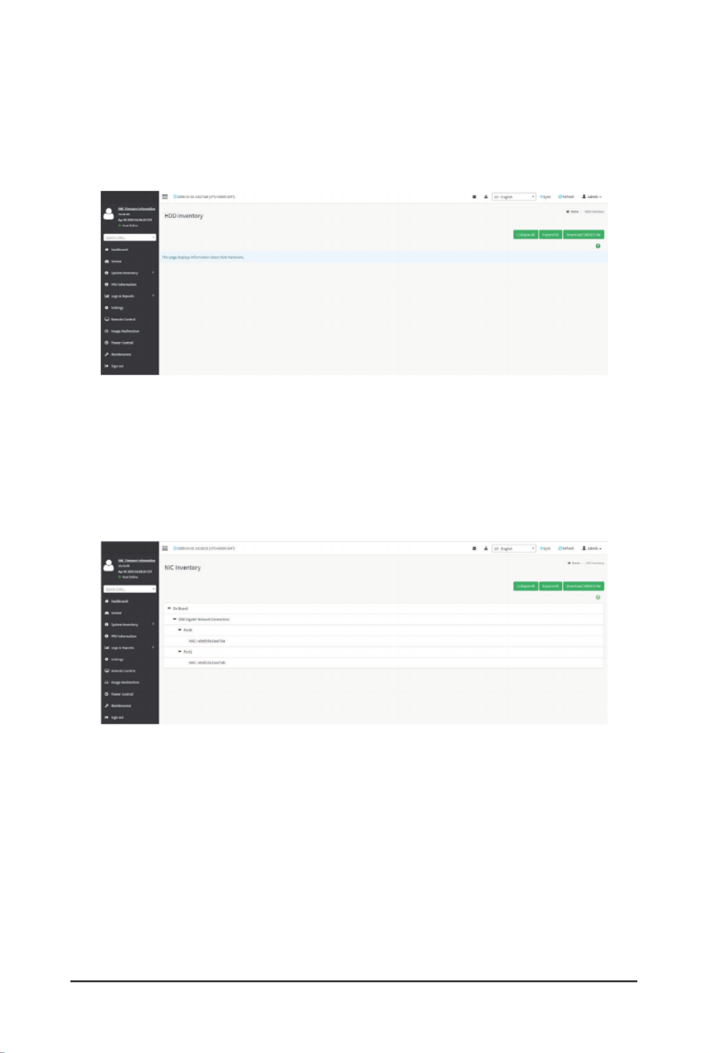
2-3-4 HDD Inventory
This page displays all detected HDDs on this device. It allows you to see on-board HDDs, add-
on HDDs or all entries in detail by clicking on . Click Expand All Download SMBIOS file to
downloadtheSMBIOSle.
2-3-5 NIC Inventory
This page displays all detected NICs on this device. It allows you to on-board NICs, add-on NICs
or all entries in detail by clicking on . Click to download the Expand All Download SMBIOS le
SMBIOSle.

- 21 - Gigabyte Server Management Console
Power Information for GPU
• Power Consumption
Clock Information for GPU
• Graphics Clock Frequency
• -Memory Clock Frequency

- 22 - Gigabyte Server Management Console
2-4 FRU Information
FRU Information page displays the BMC’s FRU device information. FRU page shows information
like Basic Information, Chassis Information, Board Information and Product Information of the
FRU device.
To open the FRU Information page, click from the menu bar. Select a FRU FRU Information
Device ID from the FRU Information section to view the details of the selected device. A
screenshot of FRU Information page is shown below.
Thefollowingeldsaredisplayedherefortheselecteddevice:
Available FRU Devices
• FRU device ID - Select the device ID from the drop down list
• FRU Device Name - The device name of the selected FRU device.
Chassis Information
• Chassis Information Area Format Version
• Chassis Type
• Chassis Part Number
• Chassis Serial Number
• Chassis Extra

Gigabyte Server Management Console - 25 -
TheEventLogpageconsistsofthefollowingelds:
Filter By Date Start Date End Date: Filtering can be done by selecting and .
:Date should be in MM/DD/YYYY format. Note
By default, all log time will be displayed in BMC time zone.
Filter By Type: The category could be either All Events, System Event Records, OEM Event
Records, BIOS Generated Events, SMI Handler Events, System Management Software Events,
System Software - OEM Events, Remote Console software Events, Terminal Mode Remote
Console software Events.
:Once the Filter By Date and Filter type are selected, the list of events will Note
be displayed with the Event ID, Time Stamp, Sensor Type, Sensor Name and
Description.
Event Log Statistics: Displays the statistical graph for the selected date.
Clear Event Logs: To delete all the event logs.
Download Event Logs: To download the event logs.
Procedure
1. using FromtheFilterByDateeld,selectthetimeperiodbyStart Date End Date and
Calendar for the event categories.
2. From the Filter By Type eld,selecttheType Sensor of the event and name to view the
events for the date. The events will be displayed based on the selected time period.
3. To clear all events from the list, click .Clear All Event Logs
4. To download the event logs, click .Download Event Logs

- 30 - Gigabyte Server Management Console
2-6-2 Date & Time
ThiseldisusedtosetthedateandtimeontheBMC.ASamplescreenshotofDate&Timeis
shown below.
TheDate&Timesectionconsistsofthefollowingelds:
Configure Date & Time: Displays Time zone list containing the UTC offset along with the
locations and Navigational line to select the location which can be used to display the exact local
time.
Select Time Zone:ThiseldisusedtosetthedateandtimeontheBMC.
Automatic Date & Time: To automatically synchronize Date and Time with the NTP Server.
Primary NTP Server:TocongureaprimaryNTPservertousewhenautomaticallysettingthe
date and time.
Secondary NTP Server:TocongureasecondaryNTPservertousewhenautomaticallysetting
the date and time.
Save:Tosavetheconguredsettings.
:If the timezone is selected as Manual Offset, the map selection will be disabled. Note
TheTime¬Zonesettingswillbereectedonlyaftersavingthesettings.
Product specificaties
| Merk: | Gigabyte |
| Categorie: | Server |
| Model: | R282-Z96 |
| Breedte: | 438 mm |
| Diepte: | 87 mm |
| Hoogte: | 730 mm |
| Breedte verpakking: | 982 mm |
| Diepte verpakking: | 588 mm |
| Hoogte verpakking: | 268 mm |
| LED-indicatoren: | HDD, LAN, Status |
| Processorfamilie: | AMD |
| Ethernet LAN: | Ja |
| VGA (D-Sub)poort(en): | 1 |
| Aantal Ethernet LAN (RJ-45)-poorten: | 2 |
| Netvoeding: | 2000 W |
| Type processor: | Nee |
| Ethernet LAN, data-overdrachtsnelheden: | 10,100,1000 Mbit/s |
| Temperatuur bij opslag: | -40 - 60 °C |
| Processor socket: | Socket SP3 |
| PCI Express slots versie: | 4.0 |
| Processorfabrikant: | AMD |
| On-board graphics adapter model: | Aspeed AST2500 |
| Luchtvochtigheid bij opslag: | 20 - 95 procent |
| Type behuizing: | Rack (2U) |
| Redundante voeding: | Ja |
| Verpakkingsinhoud: | 1 x R282-Z96 system\n2 x CPU heatsinks\n1 x Rail kit |
| Trusted Platform Module (TPM): | Ja |
| Aantal 3.5" bays: | 12 |
| Ondersteunde opslagstationinterfaces: | Serial ATA, Serial Attached SCSI (SAS) |
| LAN controller: | Intel® I350-AM2 |
| Aantal hoofdvoedingen: | 2 |
| PCI-slots: | 7 |
| Aantal ondersteunde processoren: | 2 |
| Maximum UDIMM geheugen: | 256 GB |
| Aantal DIMM sloten: | 32 |
| Ondersteunende RDIMM klok snelheden: | 2933,3200 MHz |
| Aantal storage drives ondersteund: | 12 |
| Opslagschijf afmetingen ondersteund: | 3.5 " |
| Ondersteunde geheugen types: | DDR4-SDRAM |
| Hot-swap HDD bays: | Ja |
| AC-ingangsspanning: | 110 - 240 V |
| AC-ingangsfrequentie: | 50/60 Hz |
| Bedrijfstemperatuur (T-T): | 10 - 35 °C |
| Relatieve vochtigheid in bedrijf (V-V): | 8 - 80 procent |
| Code geharmoniseerd systeem (HS): | 84714100 |
| Trusted Platform Module (TPM) version: | 2.0 |
| Ondersteunde types opslag-drives: | HDD & SSD |
| Aantal COM-poorten: | 1 |
| Aantal M.2 (M) slots: | 1 |
| DC output stroom (+ 12 V): | 163 A |
| Backplanes ondersteund: | Ja |
| DC uitgangsstroom (+ 5 V): | 81 A |
| PCI Express x24 Riser Super sleuven: | 1 |
Heb je hulp nodig?
Als je hulp nodig hebt met Gigabyte R282-Z96 stel dan hieronder een vraag en andere gebruikers zullen je antwoorden
Handleiding Server Gigabyte

1 December 2024
11 Maart 2024
11 Maart 2024
11 Maart 2024
11 Maart 2024
11 Maart 2024
11 Maart 2024
11 Maart 2024
11 Maart 2024
11 Maart 2024
Handleiding Server
- Server HP
- Server Sony
- Server Asus
- Server Medion
- Server Toshiba
- Server Abus
- Server Acer
- Server Acti
- Server Allnet
- Server Apc
- Server Asrock
- Server Axis
- Server Buffalo
- Server D-Link
- Server Dell
- Server Digi
- Server Digitus
- Server Dual Bay
- Server Eaton
- Server Elac
- Server EMC
- Server Fantec
- Server Flir
- Server Freecom
- Server Fujitsu
- Server GeoVision
- Server Hikvision
- Server Ibm
- Server In Win
- Server Iomega
- Server Kathrein
- Server LaCie
- Server Lenovo
- Server LevelOne
- Server Linksys
- Server Luxman
- Server Maxdata
- Server Megasat
- Server Monacor
- Server MSI
- Server Nec
- Server Netgear
- Server Provision ISR
- Server QNAP
- Server Quantum
- Server Revox
- Server Seagate
- Server Sitecom
- Server Sun
- Server Synology
- Server Technics
- Server Trendnet
- Server Veritas
- Server Western Digital
- Server ZyXEL
- Server Conceptronic
- Server Atlona
- Server SilverStone
- Server Intel
- Server SIIG
- Server Tripp Lite
- Server Valcom
- Server Cisco
- Server Matrox
- Server Asustor
- Server Gefen
- Server Planet
- Server Intellinet
- Server Silex
- Server Supermicro
- Server G-Technology
- Server Lindy
- Server AVerMedia
- Server Black Box
- Server Blackmagic Design
- Server ATen
- Server Extron
- Server Areca
- Server AMX
- Server SEH
- Server StarTech.com
- Server HGST
- Server Sonnet
- Server TAIDEN
- Server Advantech
- Server Moxa
- Server Smart-AVI
- Server Kramer
- Server KanexPro
- Server Avocent
- Server Teradek
- Server Vimar
- Server Hanwha
- Server Ernitec
- Server MvixUSA
- Server Promise Technology
- Server Raidsonic
- Server Rocstor
- Server Infortrend
- Server Opengear
- Server EXSYS
- Server Raritan
- Server Chenbro Micom
- Server Middle Atlantic
- Server Mr. Signal
- Server Atlantis Land
- Server C2G
- Server Lantronix
- Server IStarUSA
- Server NETSCOUT
- Server Mobotix
- Server Origin Storage
Nieuwste handleidingen voor Server

28 Maart 2025
28 Maart 2025
28 Maart 2025

10 Maart 2025
10 Maart 2025
10 Maart 2025
10 Maart 2025
10 Maart 2025
10 Maart 2025
10 Maart 2025