Gigabyte MA785GMT-UD2H Handleiding
Gigabyte
Moederbord
MA785GMT-UD2H
Lees hieronder de 📖 handleiding in het Nederlandse voor Gigabyte MA785GMT-UD2H (104 pagina's) in de categorie Moederbord. Deze handleiding was nuttig voor 28 personen en werd door 2 gebruikers gemiddeld met 4.5 sterren beoordeeld
Pagina 1/104

GA-MA785GPMT-UD2H/
GA-MA785GMT-UD2H/
GA-MA785GMT-US2H
AM3 socket motherboard for
AMD Phenom™ II processor/ AMD Athlon™ II processor
User's Manual
Rev. 1101
12ME-MA785T2-1101R

Motherboard
GA-MA785GPMT-UD2H/
GA-MA785GMT-UD2H/
GA-MA785GMT-US2H
July 16, 2009
July 16, 2009
Motherboard
GA-MA785GPMT-UD2H/GA-MA785GMT-UD2H/GA-MA785GMT-US2H

Copyright
© 2009 GIGA-BYTE TECHNOLOGY CO., LTD. All rights reserved.
The trademarks mentioned in this manual are legally registered to their respective owners.
Disclaimer
Information in this manual is protected by copyright laws and is the property of GIGABYTE.
Changes to the specications and features in this manual may be made by GIGABYTE with-
out prior notice. No part of this manual may be reproduced, copied, translated, transmitted, or
published in any form or by any means without GIGABYTE's prior written permission.
Documentation Classications
In order to assist in the use of this product, GIGABYTE provides the following types of documentations:
For quick set-up of the product, read the Quick Installation Guide included with the product.
For detailed product information, carefully read the User's Manual.
For instructions on how to use GIGABYTE's unique features, read or download the information
on/from the Support&Downloads\Motherboard\Technology Guide page on our website.
For product-related information, check on our website at:
http://www.gigabyte.com.tw
Identifying Your Motherboard Revision
The revision number on your motherboard looks like this: "REV: X.X." For example, "REV: 1.0"
means the revision of the motherboard is 1.0. Check your motherboard revision before updating
motherboard BIOS, drivers, or when looking for technical information.
Example:

- 4 -
Table of Contents
Box Contents ...................................................................................................................6
Optional Items .................................................................................................................6
GA-MA785GPMT-UD2H/GA-MA785GMT-UD2H(US2H) ................................................7
Motherboard Layout .......................................................................................................7
Block Diagram .................................................................................................................8
Chapter 1 Hardware Installation .....................................................................................9
1-1 Installation Precautions .................................................................................... 9
1-2 Product Specications .................................................................................... 10
1-3 Installing the CPU and CPU Cooler ............................................................... 13
1-3-1 Installing the CPU ...................................................................................................13
1-3-2 Installing the CPU Cooler .......................................................................................15
1-4 Installing the Memory ..................................................................................... 16
1-4-1 Dual Channel Memory Conguration .....................................................................16
1-4-2 Installing a Memory ...............................................................................................17
1-5 Installing an Expansion Card ......................................................................... 18
1-6 Setup of the ATI Hybrid CrossFireX™ Conguration ....................................... 19
1-7 Back Panel Connectors .................................................................................. 20
1-8 Internal Connectors ........................................................................................ 23
Chapter 2 BIOS Setup ..................................................................................................35
2-1 Startup Screen ............................................................................................... 36
2-2 The Main Menu .............................................................................................. 37
2-3 MB Intelligent Tweaker(M.I.T.) ........................................................................ 39
2-4 Standard CMOS Features .............................................................................. 45
2-5 Advanced BIOS Features .............................................................................. 47
2-6 Integrated Peripherals .................................................................................... 50
2-7 Power Management Setup ............................................................................. 53
2-8 PnP/PCI Congurations ................................................................................. 55
2-9 PC Health Status ............................................................................................ 56
2-10 Load Fail-Safe Defaults .................................................................................. 58
2-11 Load Optimized Defaults ................................................................................ 58
2-12 Set Supervisor/User Password ...................................................................... 59
2-13 Save & Exit Setup .......................................................................................... 60
2-14 Exit Without Saving ........................................................................................ 60

- 5 -
Chapter 3 Drivers Installation ........................................................................................61
3-1 Installing Chipset Drivers ............................................................................... 61
3-2 Application Software ...................................................................................... 62
3-3 Technical Manuals .......................................................................................... 62
3-4 Contact ........................................................................................................... 63
3-5 System ........................................................................................................... 63
3-6 Download Center ........................................................................................... 64
Chapter 4 Unique Features ...........................................................................................65
4-1 Xpress Recovery2 .......................................................................................... 65
4-2 BIOS Update Utilities ..................................................................................... 68
4-2-1 Updating the BIOS with the Q-Flash Utility .............................................................68
4-2-2 Updating the BIOS with the @BIOS Utility .............................................................71
4-3 EasyTune 6 .................................................................................................... 72
4-4 Easy Energy Saver ........................................................................................ 73
4-5 Q-Share .......................................................................................................... 75
4-6 Time Repair .................................................................................................... 76
Chapter 5 Appendix ......................................................................................................77
5-1 Conguring SATA Hard Drive(s) ..................................................................... 77
5-1-1 Conguring the Onboard SATA Controller ............................................................77
5-1-2 Making a SATA RAID/AHCI Driver Diskette ............................................................83
5-1-3 Installing the SATA RAID/AHCI Driver and Operating System ...............................84
5-2 Conguring Audio Input and Output ............................................................... 88
5-2-1 Conguring 2/4/5.1/7.1-Channel Audio ...................................................................88
5-2-2 Conguring S/PDIF In/Out ......................................................................................90
5-2-3 Enabling the Dolby Home Theater Functionjk ...................................................92
5-2-4 Conguring Microphone Recording ........................................................................93
5-2-5 Using the Sound Recorder .....................................................................................95
5-3 Troubleshooting.............................................................................................. 96
5-3-1 Frequently Asked Questions ..................................................................................96
5-3-2 Troubleshooting Procedure ....................................................................................97
5-4 Regulatory Statements ................................................................................... 99
j Only for GA-MA785GPMT-UD2H.
k Only for GA-MA785GMT-UD2H.

- 6 -
Box Contents
GA-MA785GPMT-UD2H, GA-MA785GMT-UD2H,
or GA-MA785GMT-US2H motherboard
Motherboard driver disk
User's Manual
Quick Installation Guide
One IDE cable
Two SATA 3Gb/s cables
I/O Shield
Optional Items
Floppy disk drive cable (Part No. 12CF1-1FD001-7*R)
2-port USB 2.0 bracket (Part No. 12CR1-1UB030-5*R)
2-port IEEE 1394a bracket (Part No. 12CF1-1IE008-0*R)
2-port SATA power cable (Part No. 12CF1-2SERPW-0*R)
S/PDIF In and Out cable (Part No. 12CR1-1SPINO-1*R)
COM port cable (Part No. 12CF1-1CM001-3*R)
LPT port cable (Part No. 12CF1-1LP001-0*R)
• The box contents above are for reference only and the actual items shall depend on the product package you obtain.
The box contents are subject to change without notice.
• The motherboard image is for reference only.

- 7 -
GA-MA785GPMT-UD2H/GA-MA785GMT-UD2H(US2H)
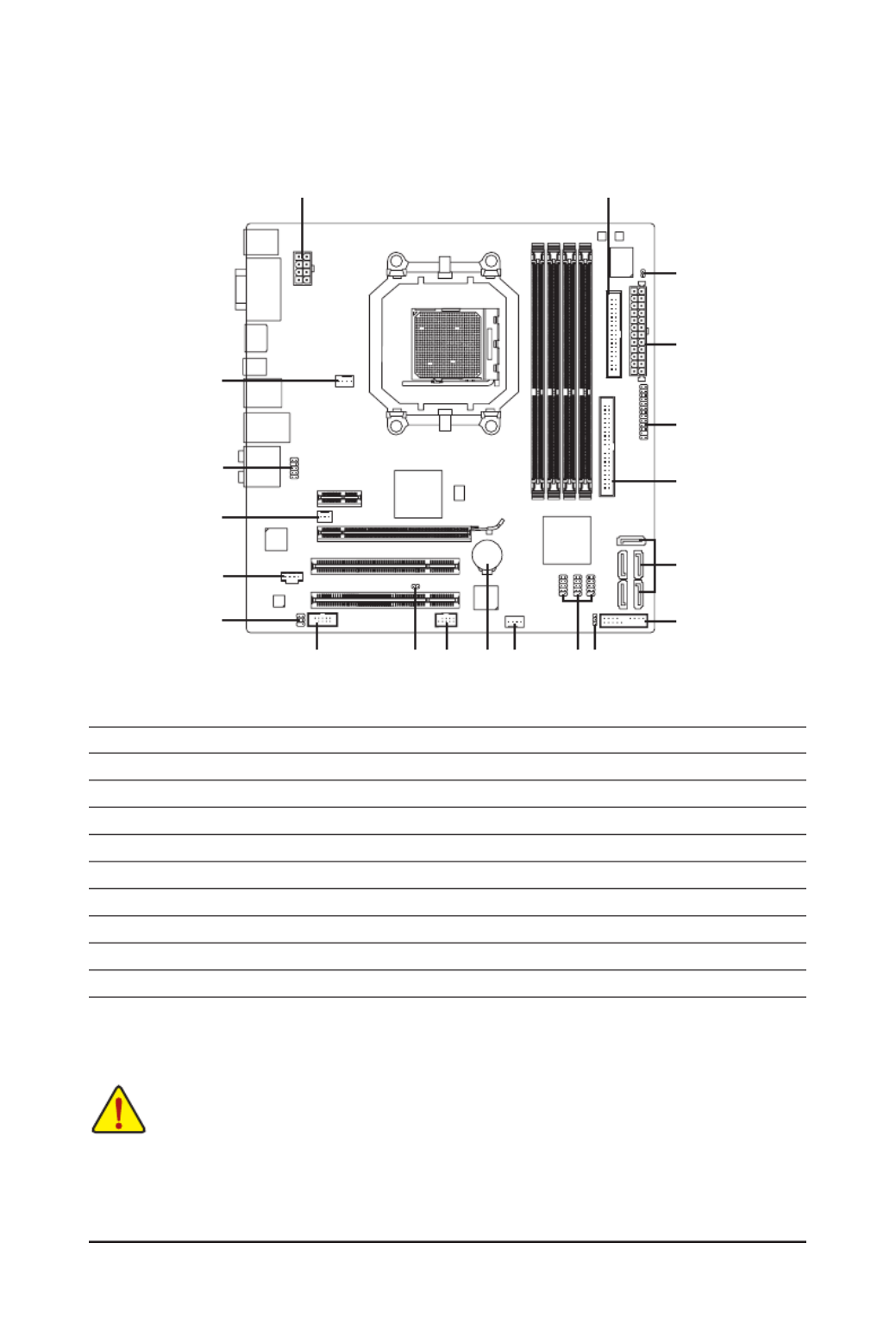
Motherboard Layout
"*" The GA-MA785GPMT-UD2H/GA-MA785GMT-UD2H adopts All-Solid Capacitor design.
j Only for GA-MA785GPMT-UD2H.
(Note) Use this port to connect a PS/2 keyboard or PS/2 mouse.
KB(Note) _USB
CPU_FAN
ATX
GA-MA785GPMT-UD2H/
GA-MA785GMT-UD2H/
GA-MA785GMT-US2H
CD_IN
F_AUDIO
AUDIO
SPDIF_IO
PCIEX1
IDE
PWR_LED
DDR3_1
DDR3_2
ATX_12V_2X4
AMD 785G
AMD SB710
SATA2_3
SATA2_0
SATA2_4
SATA2_2
SATA2_1
PCI1
DVI
VGA
CODEC
CI
OPTICAL
HDMI
USB
LAN
PCI2 CLR_CMOS
BATTERY
M_BIOS
FDD
F_PANEL
COM
RTL8111C
B_BIOS
IT8718
TSB43AB23
SYS_FAN
PCIEX16
ESATA
1394
USB
NB_FAN
F_1394_1
F_USB1
F_USB2
F_USB3
SidePort Memory
j
DDR3_3
DDR3_4
LPT
Socket AM3
- 8 -
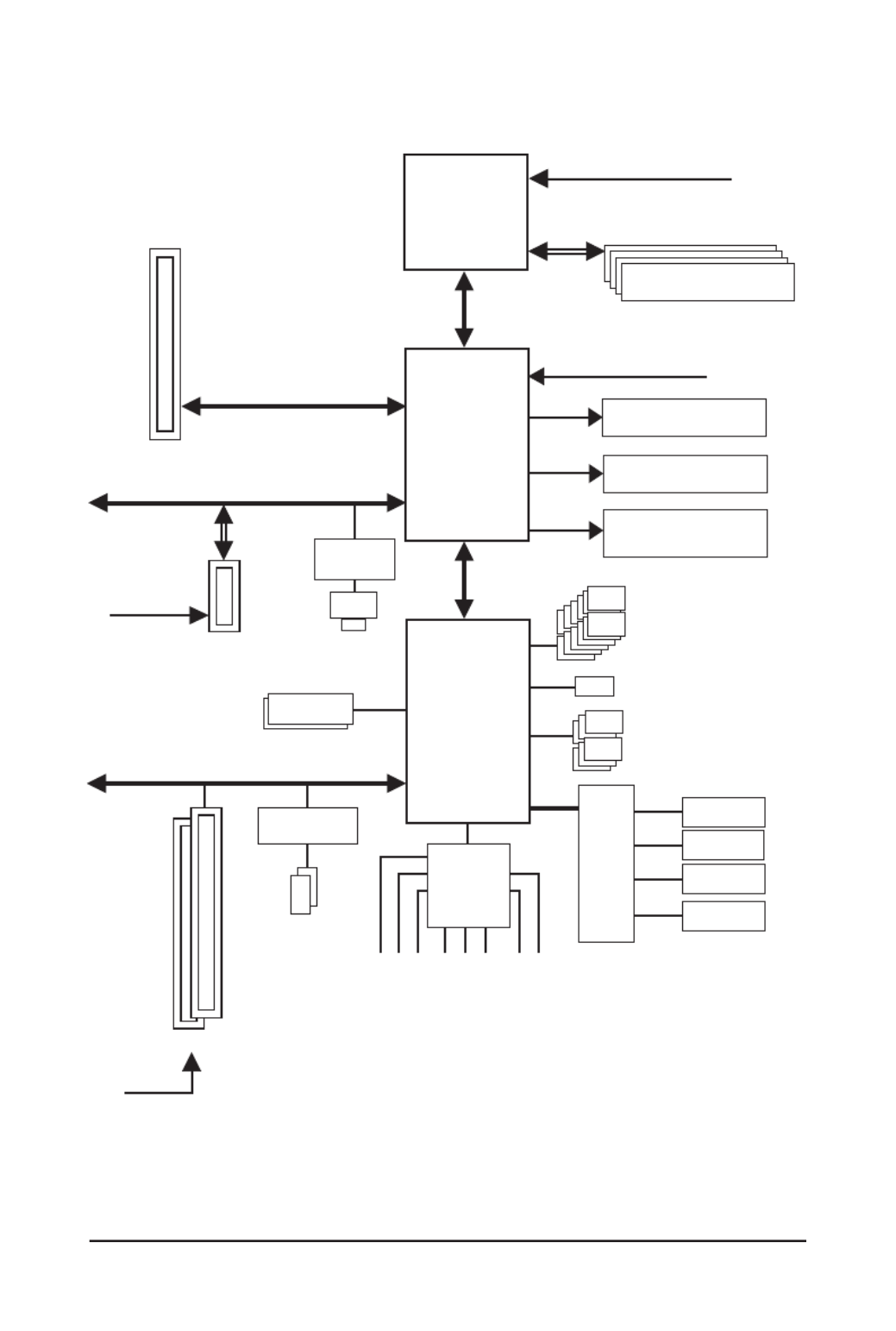
Block Diagram
AM3 CPU
Hyper Transport 3.0
AMD 785G
PCIe CLK
(100 MHz)
PCI Express Bus
CPU CLK+/- (200 MHz)
1 PCI Express x1
RTL8111C
DDR3 1666 (O.C.)/1333/1066 MHz
PCIe CLK
(100 MHz)
1 PCI Express x16
LAN
RJ45
x1
GFX CLK (100 MHz)
D-Sub
DVI-D or HDMI (Note)
PCI Express x16
j Only for GA-MA785GPMT-UD2H.
(Note) Simultaneous output for DVI-D and HDMI is not supported.
Dual Channel Memory
DDR3 SidePort
Memoryj
PS/2 KB or Mouse
AMD SB710
IT8718
Floppy
ATA-133/100/66/33 IDE Channel
COM Port
12 USB Ports
LPC
Bus
6 SATA 3Gb/s
LPT Port
Center/Subwoofer Speaker Out
Line Out
MIC
Line In
S/PDIF In
S/ PDIF Out
Side Speaker Out
Surround Speaker Out
CODEC
2 PCI
PCI Bus
PCI CLK
(33 MHz)
TSB43AB23
2 IEEE 1394a
Dual BIOS

Hardware Installation - 10 -
1-2 Product Specications
CPU Support for AM3 processors:
AMD Phenom™ II processor/ AMD Athlon™ II processor
(Go to GIGABYTE's website for the latest CPU support list.)
Hyper Transport Bus 5200 MT/s
Chipset North Bridge: AMD 785G
South Bridge: AMD SB710
Memory 4 x 1.5V DDR3 DIMM sockets supporting up to 16 GB of system memory (Note 1)
Dual channel memory architecture
Support for DDR3 1666 (O.C.)/1333/1066 MHz memory modules
(Go to GIGABYTE's website for the latest memory support list.)
Intergrated Memory
128MB DDR3 SidePort memory
Onboard Graphics Integrated in the North Bridge:
- 1 x D-Sub port
- 1 x DVI-D port
(Note 2) (Note 3)
- 1 x HDMI port (Note 3)
Audio Realtek ALC889A codec
High Denition Audio
2/4/5.1/7.1-channel
Support for Dolby® Home Theater jk
Support for S/PDIF In/Out
Support for CD In
LAN RTL8111C chip (10/100/1000 Mbit)
Expansion Slots 1 x PCI Express x16 slot, running at x16
(The PCI Express x16 slot conforms to PCI Express 2.0 standard.)
1 x PCI Express p10-x1 slot
2 x PCI slots
Storage Interface South Bridge:
- 1 x IDE connector supporting ATA-133/100/66/33 and up to 2 IDE devices
- 5 x SATA 3Gb/s connectors (SATA2_0, SATA2_1, SATA2_2, SATA2_3,
SATA2_4) supporting up to 5 SATA 3Gb/s devices
- 1 x eSATA 3Gb/s port on the back panel supporting up to 1 SATA 3Gb/s
device
- Support for SATA RAID 0, RAID 1, RAID 10, and JBOD
iTE IT8718 chip:
- 1 x oppy disk drive connector supporting up to 1 oppy disk drive
"*" The GA-MA785GPMT-UD2H/GA-MA785GMT-UD2H adopts All-Solid Capacitor design.
j Only for GA-MA785GPMT-UD2H.
k Only for GA-MA785GMT-UD2H.

- 11 - Hardware Installation
USB Integrated in the South Bridge
Up to 12 USB 2.0/1.1 ports (6 on the back panel, 6 via the USB brackets
connected to the internal USB headers)
IEEE 1394 T.I. TSB43AB23 chip
Up to 2 IEEE 1394a ports (1 on the back panel, 1 via the IEEE 1394a bracket
connected to the internal IEEE 1394a header)
Internal 1 x 24-pin ATX main power connector
Connectors 1 x 8-pin ATX 12V power connector
1 x oppy disk drive connector
1 x IDE connector
5 x SATA 3Gb/s connectors
1 x CPU fan header
1 x system fan header
1 x North Bridge fan header
1 x front panel header
1 x front panel audio header
1 x CD In connector
1 x S/PDIF In/Out header
3 x USB 2.0/1.1 headers
1 x IEEE 1394a header
1 x serial port header
1 x parallel port header
1 x power LED header
1 x chassis intrusion header
1 x clearing CMOS jumper
Back Panel 1 x PS/2 keyboard port or PS/2 mouse port
Connectors 1 x D-Sub port
1 x DVI-D port (Note 2) (Note 3)
1 x HDMI port (Note 3)
1 x optical S/PDIF Out connector
1 x eSATA 3Gb/s port
1 x IEEE 1394a port
6 x USB 2.0/1.1 ports
1 x RJ-45 port
6 x audio jacks (Center/Subwoofer Speaker Out/Rear Speaker Out/
Side Speaker Out/Line In/Line Out/Microphone)
I/O Controller iTE IT8718 chip
Hardware Monitor System voltage detection
CPU/System temperature detection
CPU/System fan speed detection
CPU overheating warning
CPU/System/Power fan fail warning
CPU/System fan speed control (Note 4)

Hardware Installation - 12 -
(Note 1) Due to Windows Vista/XP 32-bit operating system limitation, when more than 4 GB of physical
memory is installed, the actual memory size displayed will be less than 4 GB.
(Note 2) The DVI-D port does not support D-Sub connection by adapter.
(Note 3) Simultaneous output for DVI-D and HDMI is not supported.
(Note 4) Whether the CPU/system fan speed control function is supported will depend on the CPU/system
cooler you install.
(Note 5) Available functions in EasyTune may differ by motherboard model.
BIOS 2 x 8 Mbit ash
Use of licensed AWARD BIOS
Support for DualBIOS™
PnP 1.0a, DMI 2.0, SM BIOS 2.4, ACPI 1.0b
Unique Features Support for @BIOS
Support for Q-Flash
Support for Xpress BIOS Rescue
Support for Download Center
Support for Xpress Install
Support for Xpress Recovery2
Support for EasyTune (Note 5)
Support for Easy Energy Saver
Support for Time Repair
Support for Q-Share
Bundled Software Norton Internet Security (OEM version)
Operating System Support for Microsoft® Windows® Vista/XP
Form Factor Micro ATX Form Factor; 24.3cm x 24.3cm

- 13 - Hardware Installation
1-3 Installing the CPU and CPU Cooler
1-3-1 Installing the CPU
A. Locate the pin one (denoted by a small triangle) of the CPU socket and the CPU.
Read the following guidelines before you begin to install the CPU:
• Make sure that the motherboard supports the CPU.
(Go to GIGABYTE's website for the latest CPU support list.)
• Always turn off the computer and unplug the power cord from the power outlet before installing
the CPU to prevent hardware damage.
• Locate the pin one of the CPU. The CPU cannot be inserted if oriented incorrectly. (Or you may
locate the notches on both sides of the CPU and alignment keys on the CPU socket.)
• Apply an even and thin layer of thermal grease on the surface of the CPU.
• Do not turn on the computer if the CPU cooler is not installed, otherwise overheating and dam-
age of the CPU may occur.
• Set the CPU host frequency in accordance with the CPU specications. It is not recommended
that the system bus frequency be set beyond hardware specications since it does not meet the
standard requirements for the peripherals. If you wish to set the frequency beyond the standard
specications, please do so according to your hardware specications including the CPU, graph-
ics card, memory, hard drive, etc.
AM3 CPU
AM3 Socket
A Small Triangle Marking
Denotes CPU Pin One
A Small Triangle Mark
Denotes Pin One of the
Socket

Hardware Installation - 14 -
B. Follow the steps below to correctly install the CPU into the motherboard CPU socket.
• Before installing the CPU, make sure to turn off the computer and unplug the power cord from the
power outlet to prevent damage to the CPU.
• Do not force the CPU into the CPU socket. The CPU cannot t in if oriented incorrectly. Adjust the
CPU orientation if this occurs.
Step 1:
Completely lift up the CPU socket locking lever.
Step 2:
Align the CPU pin one (small triangle marking) with the triangle mark
on the CPU socket and gently insert the CPU into the socket. Make
sure that the CPU pins t perfectly into their holes. Once the CPU is
positioned into its socket, place one nger down on the middle of the
CPU, lowering the locking lever and latching it into the fully locked
position.
CPU Socket
Locking Lever

Hardware Installation - 16 -
1-4 Installing the Memory
DDR3_1
DDR3_2
DDR3_3
DDR3_4
Read the following guidelines before you begin to install the memory:
• Make sure that the motherboard supports the memory. It is recommended that memory of the
same capacity, brand, speed, and chips be used.
(Go to GIGABYTE's website for the latest memory support list.)
• Always turn off the computer and unplug the power cord from the power outlet before installing
the memory to prevent hardware damage.
• Memory modules have a foolproof design. A memory module can be installed in only one direc-
tion. If you are unable to insert the memory, switch the direction.
If two memory modules are to be installed, it is rec-
ommended that you install them in the DDR3_1 and
DDR3_2 sockets.
Dual Channel Memory Congurations Table
(SS=Single-Sided, DS=Double-Sided, "- -"=No Memory)
DDR3_1 DDR3_2 DDR3_3 DDR3_4
DS/SS DS/SS - - - -
- - - - DS/SS DS/SS
DS/SS DS/SS DS/SS DS/SS
Two Modules
Four Modules
1-4-1 Dual Channel Memory Conguration
This motherboard provides four DDR3 memory sockets and supports Dual Channel Technology. After the
memory is installed, the BIOS will automatically detect the specications and capacity of the memory. En-
abling Dual Channel memory mode will double the original memory bandwidth.
The four DDR3 memory sockets are divided into two channels and each channel has two memory sockets as
following:
Channel 0: DDR3_1, DDR3_3
Channel 1: DDR3_2, DDR3_4
Due to CPU limitations, read the following guidelines before installing the memory in Dual Channel mode.
1. Dual Channel mode cannot be enabled if only one DDR3 memory module is installed.
2. When enabling Dual Channel mode with two or four memory modules, it is recommended that
memory of the same capacity, brand, speed, and chips be used and installed in the same colored
DDR3 sockets for optimum performance.

- 17 - Hardware Installation
1-4-2 Installing a Memory
Notch
Before installing a memory module, make sure to turn off the computer and unplug the power
cord from the power outlet to prevent damage to the memory module.
DDR3 and DDR2 DIMMs are not compatible to each other or DDR DIMMs. Be sure to install
DDR3 DIMMs on this motherboard.
DDR3 DIMM
A DDR3 memory module has a notch, so it can only t in one direction. Follow the steps below to correctly
install your memory modules in the memory sockets.
Step 1:
Note the orientation of the memory module. Spread the retaining
clips at both ends of the memory socket. Place the memory module
on the socket. As indicated in the picture on the left, place your n-
gers on the top edge of the memory, push down on the memory and
insert it vertically into the memory socket.
Step 2:
The clips at both ends of the socket will snap into place when the
memory module is securely inserted.

Hardware Installation - 18 -
1-5 Installing an Expansion Card
Read the following guidelines before you begin to install an expansion card:
• Make sure the motherboard supports the expansion card. Carefully read the manual that came
with your expansion card.
• Always turn off the computer and unplug the power cord from the power outlet before installing
an expansion card to prevent hardware damage.
Follow the steps below to correctly install your expansion card in the expansion slot.
1. Locate an expansion slot that supports your card. Remove the metal slot cover from the chassis back panel.
2. Align the card with the slot, and press down on the card until it is fully seated in the slot.
3. Make sure the metal contacts on the card are completely inserted into the slot.
4. Secure the card’s metal bracket to the chassis back panel with a screw.
5. After installing all expansion cards, replace the chassis cover(s).
6. Turn on your computer. If necessary, go to BIOS Setup to make any required BIOS changes for your
expansion card(s).
7. Install the driver provided with the expansion card in your operating system.
Example: Installing and Removing a PCI Express Graphics Card:
• Installing a Graphics Card:
Gently push down on the top edge of the card until
it is fully inserted into the PCI Express slot. Make
sure the card is securely seated in the slot and
does not rock.
PCI Slot
PCI Express p18-x1 Slot
PCI Express x16 Slot
• Removing the Card from the PCIEX16_1 slot:
Gently push back on the lever on the slot and then lift the card straight out from
the slot.

Hardware Installation - 20 -
1-7 Back Panel Connectors
USB Port
The USB port supports the USB 2.0/1.1 specication. Use this port for USB devices such as a USB key-
board/mouse, USB printer, USB ash drive and etc.
PS/2 Keyboard or PS/2 Mouse Port
Use this port to connect a PS/2 keyboard or PS/2 mouse.
D-Sub Port
The D-Sub port supports a 15-pin D-Sub connector. Connect a monitor that supports D-Sub connection
to this port.
DVI-D Port (Note 1)(Note 2)
The DVI-D port supports DVI-D specictation. Connect a monitor that supports DVI-D connection to this
port.
HDMI Port
(Note 2)
The HDMI (High-Denition Multimedia Interface) provides an all-digital audio/video interface to transmit
the uncompressed audio/video signals and is HDCP compliant. Connect the HDMI audio/video device to
this port. The HDMI Technology can support a maximum resolution of 1920x1080p but the actual resolu-
tions supported depend on the monitor being used.
In Windows Vista, select Start>Control Panel>Sound, select Realtek
HDMI Output Set Default and then click .
(Note 1) The DVI-D port does not support D-Sub connection by adapter.
(Note 2) Simultaneous output for DVI-D and HDMI is not supported.
(Note 1) (Note 2)
(Note 2)
• After installing the HDMI device, make sure the default device for sound playback is the HDMI
device. (The item name may differ by operating system. The following screen is from Win-
dows Vista.)
• Please note the HDMI audio output only supports AC3, DTS and 2-channel-LPCM formats.
(AC3 and DTS require the use of an external decoder for decoding.)
- 23 - Hardware Installation
1-8 Internal Connectors
Read the following guidelines before connecting external devices:
• First make sure your devices are compliant with the connectors you wish to connect.
• Before installing the devices, be sure to turn off the devices and your computer. Unplug the
power cord from the power outlet to prevent damage to the devices.
• After installing the device and before turning on the computer, make sure the device cable has
been securely attached to the connector on the motherboard.
1) ATX_12V_2X4
2) ATX
3) CPU_FAN
4) SYS_FAN
5) NB_FAN
6) FDD
7) IDE
8) SATA2_0/1/2/3/4
9) PWR_LED
10) F_PANEL
11) F_AUDIO
12) CD_IN
13) SPDIF_IO
14) F_USB1/F_USB2/F_USB3
15) F_1394_1
16) LPT
17) COM
18) CI
19) CLR_CMOS
20) BATTERY
1
3
11
12
17 19 15 20 4 14
8
7
16
2
6
5
13
9
10
18

Hardware Installation - 24 -
ATX_12V_2X4:
ATX_12V_2X4
4
1
8
5
ATX:
Pin No. Denition
13 3.3V
14 -12V
15 GND
16 PS_ON (soft On/Off)
17 GND
18 GND
19 GND
20 -5V
21 +5V
22 +5V
23 +5V (Only for 2x12-pin ATX)
24 GND (Only for 2x12-pin ATX)
Pin No. Denition
1 3.3V
2 3.3V
3 GND
4 +5V
5 GND
6 +5V
7 GND
8 Power Good
9 5VSB (stand by +5V)
10 +12V
11 +12V (Only for 2x12-pin ATX)
12 3.3V (Only for 2x12-pin ATX)
1/2) ATX_12V_2X4/ATX (2x4 12V Power Connector and 2x12 Main Power Connector)
With the use of the power connector, the power supply can supply enough stable power to all the com-
ponents on the motherboard. Before connecting the power connector, rst make sure the power supply
is turned off and all devices are properly installed. The power connector possesses a foolproof design.
Connect the power supply cable to the power connector in the correct orientation. The 12V power con-
nector mainly supplies power to the CPU. If the 12V power connector is not connected, the computer will
not start.
• To meet expansion requirements, it is recommended that a power supply that can withstand
high power consumption be used (500W or greater). If a power supply is used that does not
provide the required power, the result can lead to an unstable or unbootable system.
• The power connectors are compatible with power supplies with 2x2 12V and 2x10 power
connectors. When using a power supply providing a 2x4 12V and a 2x12 power connector,
remove the protective covers from the 12V power connector and the main power connector on
the motherboard. Do not insert the power supply cables into pins under the protective covers
when using a power supply providing a 2x2 12V and a 2x10 power connector.
Pin No. Denition
1 GND (Only for 2x4-pin 12V)
2 GND (Only for 2x4-pin 12V)
3 GND
4 GND
5 +12V (Only for 2x4-pin 12V)
6 +12V (Only for 2x4-pin 12V)
7 +12V
8 +12V
13
1
24
12
ATX
Product specificaties
| Merk: | Gigabyte |
| Categorie: | Moederbord |
| Model: | MA785GMT-UD2H |
| Breedte: | 243 mm |
| Diepte: | 243 mm |
| Type stroombron: | ATX |
| Aantal USB 2.0-poorten: | 6 |
| VGA (D-Sub)poort(en): | 1 |
| Aantal HDMI-poorten: | 1 |
| Microfoon, line-in ingang: | Ja |
| Aantal Ethernet LAN (RJ-45)-poorten: | 1 |
| Hoofdtelefoonuitgangen: | 6 |
| DVI-D poorten: | 1 |
| Processor socket: | Socket AM3 |
| Processorfabrikant: | AMD |
| Maximum intern geheugen: | 16 GB |
| Ingebouwde grafische adapter: | Ja |
| Compatibele besturingssystemen: | Windows Vista/XP |
| Audio-uitgangskanalen: | 7.1 kanalen |
| Chipset moederbord: | AMD 785G |
| Aantal IEEE 1394-/Firewire-poorten: | 1 |
| PCI Express x1 slots: | 1 |
| PCI Express x16 slots: | 1 |
| S/PDIF-uitgang: | Ja |
| PS/2 poort(en): | 1 |
| Geheugen voltage: | 1.5 V |
| LAN controller: | Realtek RTL8111C |
| PCI-slots: | 2 |
| Aantal eSATA-poorten: | 1 |
| Moederbord form factor: | micro ATX |
| Aantal geheugenslots: | 4 |
| Grootte BIOS-geheugen: | 64 Mbit |
| ACPI version: | 1.0 |
| COM aansluitingen: | 1 |
| Aansluiting voor CPU koeler: | Ja |
| Aansluitingen voor behuizingsventilatoren: | 1 |
| ATX Power connector (24-pin): | Ja |
| Aantal SATA-aansluitingen: | 5 |
| USB 2.0 aansluitingen: | 3 |
| Aansluiting voor audiopaneel aan voorzijde: | Ja |
| Aansluiting voor diskettestation: | Ja |
| Chassis intrusion aansluiting: | Ja |
| S/PDIF uitgang: | Ja |
| IEEE1394 aansluitingen: | 1 |
| CD/AUX audio-ingang: | Ja |
| Aantal Parallel ATA aansluitingen: | 1 |
| Grafische controller: | 785G |
| Soort aansluiting (2de) controller: | IDE/SATA2/eSATA |
| Aansluitingen voor EATX voedingen: | 1 |
| S/PDIF in connector: | Ja |
| Optische drivecontroller: | Dual channel |
Heb je hulp nodig?
Als je hulp nodig hebt met Gigabyte MA785GMT-UD2H stel dan hieronder een vraag en andere gebruikers zullen je antwoorden
Handleiding Moederbord Gigabyte

10 Maart 2025
11 Februari 2025
11 Februari 2025
11 Februari 2025
11 Februari 2025
11 Februari 2025
11 Februari 2025
11 Februari 2025
11 Februari 2025
11 Februari 2025
Handleiding Moederbord
- Moederbord Asus
- Moederbord Asrock
- Moederbord EPoX
- Moederbord Evga
- Moederbord MSI
- Moederbord Sharkoon
- Moederbord NZXT
- Moederbord Intel
- Moederbord Supermicro
- Moederbord ECS
- Moederbord Foxconn
- Moederbord Advantech
- Moederbord Elitegroup
- Moederbord Biostar
Nieuwste handleidingen voor Moederbord

8 April 2025
8 April 2025
3 April 2025
3 April 2025
3 April 2025
3 April 2025
2 April 2025
2 April 2025

29 Maart 2025
27 Maart 2025