Gigabyte B840M AORUS ELITE WIFI6E Handleiding
Gigabyte
Moederbord
B840M AORUS ELITE WIFI6E
Lees hieronder de 📖 handleiding in het Nederlandse voor Gigabyte B840M AORUS ELITE WIFI6E (39 pagina's) in de categorie Moederbord. Deze handleiding was nuttig voor 22 personen en werd door 2 gebruikers gemiddeld met 4.5 sterren beoordeeld
Pagina 1/39

B840M AORUS ELITE WIFI6E
(B840M A ELITE WIFI6E)
User's Manual
Rev. 1001
GIGABYTE will reduce paper use in order to fulll the responsibilities of a global citizen.
Also, to reduce the impacts on global warming, the packaging materials of this product
are recyclable and reusable. GIGABYTE works with you to protect the environment.
For more product details, please visit GIGABYTE's website.

Copyright
© 2024 GIGA-BYTE TECHNOLOGY CO., LTD. All rights reserved.
The trademarks mentioned in this manual are legally registered to their respective owners.
Disclaimer
Information in this manual is protected by copyright laws and is the property of GIGABYTE.
Changes to the specications and features in this manual may be made by GIGABYTE without
prior notice. No part of this manual may be reproduced, copied, translated, transmitted, or
published in any form or by any means without GIGABYTE's prior written permission.
For detailed product information, carefully read the User's Manual.
For quick set-up of the product, refer to the Quick Installation Guide on GIGABYTE's
website.
https://download.gigabyte.com/FileList/Manual/mb_manual_installation-guide_800series.pdf
For product-related information, check on our website at: https://www.gigabyte.com
Identifying Your Motherboard Revision
The revision number on your motherboard looks like this: "REV: X.X." For example, "REV: 1.0"
means the revision of the motherboard is 1.0. Check your motherboard revision before updating
motherboard BIOS, drivers, or when looking for technical information.
Example:

- 3 -
Table of Contents
Chapter 1 Product Introduction .......................................................................................4
1-1 Motherboard Layout ......................................................................................... 4
1-2 Motherboard Block Diagram ............................................................................ 5
1-3 Box Contents .................................................................................................... 6
Chapter 2 Hardware Installation .....................................................................................7
2-1 Installation Precautions .................................................................................... 7
2-2 Product Specications 8 ......................................................................................
2-3 Installing the CPU and CPU Cooler ............................................................... 11
2-4 Installing the Memory ..................................................................................... 14
2-5 Installing an Expansion Card ......................................................................... 15
2-6 Back Panel Connectors .................................................................................. 16
2-7 Onboard Button and LEDs 18 .............................................................................
2-8 Internal Connectors ........................................................................................ 19
Chapter 3 BIOS Setup ..................................................................................................31
Chapter 4 Installing the Operating System and Drivers ................................................33
4-1 Operating System Installation ........................................................................ 33
4-2 Drivers Installation 34 ..........................................................................................
Chapter 5 Appendix ......................................................................................................35
5-1 Conguring a RAID Set .................................................................................. 35
Regulatory Notices .................................................................................................... 36
Contact Us 39 ................................................................................................................

- 4 -
1-1 Motherboard Layout
M2_WIFI
Socket AM5
ATX
AUDIO
DDR5_A1
DDR5_A2
DDR5_B1
DDR5_B2
BAT
AMD
Chipset
M_BIOS
CODEC
PCIEX16
PCIEX4
FU3C_5G
FAN4_PUMP
80
M2A_CPU
80110
M2B_CPU
B840M AORUS ELITE WIFI6E
FUSB_1 SYS_FAN3ARGB_V2_1 SYS_FAN1ESPI_DBF_AUDIO
SPI_TPM FUSB_2LED_CARGB_V2_3 SYS_FAN2 F_PANEL
CPU_OPT
CPU_FAN
iTE®
Super I/O
RESET
RST
ARGB_V2_2
ATX_12V
SATA3
FU3A_5G
2 0
3 1
CPU DRAM
VGA BOOT
Chapter 1 Product Introduction
Realtek®
2.5GbE LAN
USB 2.0 Hub
DP_HDMI
QF_PLUS
QFLED
U35G_LAN
USB
U3A_10G
U3C_5G
PS2_USB
CLR_CMOS
Temperature sensor

- 5 -
1-2 Motherboard Block Diagram
(Note) Actual support may vary by CPU.
USB 2.0
Hub
AM5 CPU
CPU CLK+/- (100 MHz)
LAN
RJ45
PCI Express 3.0 Bus
PCI Express Bus
2 USB 3.2 Gen 1
2 USB 3.2 Gen 1
4 USB 2.0/1.1
4 USB 2.0/1.1
x1 x1
M.2 WIFI
PCI Express 4.0 Bus
PCI Express 4.0 Bus
Realtek®
2.5GbE LAN
1 USB Type-C®,
with USB 3.2 Gen 1 support
1 USB Type-C®
,
with USB 3.2 Gen 1 support
1 USB 3.2 Gen 2 Type-A
DDR5 5200/4800/4400 MT/s
x16/x8/x4 (Note)
Line Out
MIC
Line In
CODEC
PCIe x4
eSPI
Bus
SPI
Bus
iTE®
Super I/O
BIOS
TPM
1 DisplayPort (Note)
1 HDMI (Note)
AMD Chipset
1 PCI Express x16
x4
x4/x2 (Note)
1 M.2 Socket 3
(M2A_CPU)
1 M.2 Socket 3
(M2B_CPU)
x4
1 PCI Express x4
4 SATA 6Gb/s

- 6 -
1-3 Box Contents
5B840M AORUS ELITE WIFI6E motherboard
5User's Manual
5Quick Installation Guide
5One antenna
5Two SATA cables
5One G Connector
5Two packs of M.2 thick/thin rubber pads
* The box contents above are for reference only and the actual items shall depend on the product package you obtain.
The box contents are subject to change without notice.

- 7 -
2-1 Installation Precautions
The motherboard contains numerous delicate electronic circuits and components which can become
damaged as a result of electrostatic discharge (ESD). Prior to installation, carefully read the user's
manual and follow these procedures:
•Prior to installation, make sure the chassis is suitable for the motherboard.
•Prior to installation, do not remove or break motherboard S/N (Serial Number) sticker or
warranty sticker provided by your dealer. These stickers are required for warranty validation.
•Always remove the AC power by unplugging the power cord from the power outlet before
installing or removing the motherboard or other hardware components.
•When connecting hardware components to the internal connectors on the motherboard, make
sure they are connected tightly and securely.
•When handling the motherboard, avoid touching any metal leads or connectors.
•It is best to wear an electrostatic discharge (ESD) wrist strap when handling electronic
components such as a motherboard, CPU or memory. If you do not have an ESD wrist strap,
keep your hands dry and rst touch a metal object to eliminate static electricity.
•Prior to installing the motherboard, please have it on top of an antistatic pad or within an
electrostatic shielding container.
•Before connecting or unplugging the power supply cable from the motherboard, make sure
the power supply has been turned off.
•Before turning on the power, make sure the power supply voltage has been set according to
the local voltage standard.
•Before using the product, please verify that all cables and power connectors of your hardware
components are connected.
•To prevent damage to the motherboard, do not allow screws to come in contact with the
motherboard circuit or its components.
•Make sure there are no leftover screws or metal components placed on the motherboard or
within the computer casing.
•Do not place the computer system on an uneven surface.
•Do not place the computer system in a high-temperature or wet environment.
•Turning on the computer power during the installation process can lead to damage to system
components as well as physical harm to the user.
•If you are uncertain about any installation steps or have a problem related to the use of the
product, please consult a certied computer technician.
•If you use an adapter, extension power cable, or power strip, ensure to consult with its
installation and/or grounding instructions.
Chapter 2 Hardware Installation

- 8 -
2-2 ProductSpecications
CPU AMD Socket AM5, support for:
AMD Ryzen™ 9000 Series Processors/
AMD Ryzen™ 8000 Series Processors/
AMD Ryzen™ 7000 Series Processors
(Go to GIGABYTE's website for the latest CPU support list.)
Chipset AMD B840
Memory Support for DDR5 5200/4800/4400 MT/s memory modules
4 x DDR5 DIMM sockets supporting up to 256 GB (64 GB single DIMM capacity)
of system memory
Dual channel memory architecture
Support for non-ECC Un-buffered DIMM 1Rx8/2Rx8/1Rx16 memory modules
Support for AMD EXtended Proles for Overclocking (AMD EXPO™) and Extreme
Memory Prole (XMP) memory modules
(The CPU and memory conguration may affect the supported memory types, data
rate (speed), and number of DRAM modules, please refer to "Memory Support
List" on GIGABYTE's website for more information.)
Onboard
Graphics
Integrated Graphics Processor with AMD Radeon™ Graphics support:
- 1 x DisplayPort, supporting a maximum resolution of 3840x2160@144 Hz
* Support for DisplayPort 1.4 version and HDR.
- 1 x HDMI port, supporting a maximum resolution of 4096x2160@60 Hz
* Support for HDMI 2.1 version, HDCP 2.3, and HDR.
** Support for native HDMI 2.1 TMDS compatible ports.
(Graphics specications may vary depending on CPU support.)
Audio Realtek® Audio CODEC
High Denition Audio
2/4/5.1/7.1-channel
* You can change the functionality of an audio jack using the audio software. To congure
7.1-channel audio, access the audio software for audio settings.
LAN Realtek® 2.5GbE LAN chip (2.5 Gbps/1 Gbps/100 Mbps)
Wireless
Communication
Module
Realtek® Wi-Fi 6E RTL8852CE
- WIFI a, b, g, n, ac, ax, supporting 2.4/5/6 GHz carrier frequency bands
- BLUETOOTH 5.3
- Support for 11ax 160MHz wireless standard
(Actual data rate may vary depending on environment and equipment.)
Expansion Slots 1 x PCI Express x16 slot (PCIEX16), integrated in the CPU:
AMD Ryzen™
9000/7000 Series Processors support PCIe 4.0 x16 mode
AMD Ryzen™
8000 Series-Phoenix 1 Processors support PCIe 4.0 x8 mode
AMD Ryzen™
8000 Series-Phoenix 2 Processors support PCIe 4.0 x4 mode
* The PCIEX16 slot can only support a graphics card or an NVMe SSD. If only one
graphics card is to be installed, be sure to install it in the PCIEX16 slot.
Chipset:
- 1 x PCI Express x16 slot, supporting PCIe 3.0 and running at p8-x4 (PCIEX4)

- 9 -
Storage Interface 1 x M.2 connector (M2A_CPU), integrated in the CPU, supporting Socket 3,
M key, type 2580/2280 SSDs:
AMD Ryzen™
9000/7000 Series Processors support PCIe 4.0 x4/x2 SSDs
AMD Ryzen™ 8000 Series-Phoenix 1 Processors support PCIe 4.0 x4/x2 SSDs
AMD Ryzen™ 8000 Series-Phoenix 2 Processors support PCIe 4.0 x4/x2 SSDs
1 x M.2 connector (M2B_CPU), integrated in the CPU, supporting Socket 3,
M key, type 22110/2280 SSDs:
AMD Ryzen™
9000/7000 Series Processors support PCIe 4.0 x4/x2 SSDs
AMD Ryzen™ 8000 Series-Phoenix 1 Processors support PCIe 4.0 x4/x2 SSDs
AMD Ryzen™
8000 Series-Phoenix 2 Processors support PCIe 4.0 x2 SSDs
4 x SATA 6Gb/s connectors
RAID 0, RAID 1, RAID 5, and RAID 10 support for NVMe SSD storage devices
* RAID 5 is only available on AMD Ryzen™ 9000 Series Processors.
RAID 0, RAID 1, and RAID 10 support for SATA storage devices
USB CPU:
- 1 x USB Type-C® port on the back panel, with USB 3.2 Gen 1 support
- 2 x USB 3.2 Gen 1 ports on the back panel
CPU+USB 2.0 Hub:
- 4 x USB 2.0/1.1 ports on the back panel
Chipset:
- 1 x USB Type-C® port with USB 3.2 Gen 1 support, available through the
internal USB header
- 1 x USB 3.2 Gen 2 Type-A port (red) on the back panel
- 2 x USB 3.2 Gen 1 ports available through the internal USB header
- 4 x USB 2.0/1.1 ports available through the internal USB headers
Internal
Connectors
1 x 24-pin ATX main power connector
1 x 8-pin ATX 12V power connector
1 x CPU fan header
1 x CPU fan/water cooling pump header
3 x system fan headers
1 x system fan/water cooling pump header
3 x addressable RGB Gen2 LED strip headers
1 x RGB LED strip header
2 x M.2 Socket 3 connectors
4 x SATA 6Gb/s connectors
1 x front panel header
1 x front panel audio header
1 x USB Type-C ®
header, with USB 3.2 Gen 1 support
1 x USB 3.2 Gen 1 header
2 x USB 2.0/1.1 headers
1 x Trusted Platform Module header (For the GC-TPM2.0 SPI/GC-TPM2.0 SPI 2.0/
GC-TPM2.0 SPI V2 module only)
1 x reset button
1 x reset jumper
1 x Clear CMOS jumper

- 10 -
Back Panel
Connectors
1 x DisplayPort (Note)
1 x HDMI port (Note)
1 x PS/2 keyboard/mouse port
1 x Q-Flash Plus button
4 x USB 2.0/1.1 ports
2 x USB 3.2 Gen 1 ports
1 x USB 3.2 Gen 2 Type-A port (red)
1 x USB Type-C® port, with USB 3.2 Gen 1 support
1 x RJ-45 port
2 x antenna connectors (2T2R)
3 x audio jacks
I/O Controller iTE® I/O Controller Chip
Hardware
Monitor
Voltage detection
Temperature detection
Fan speed detection
Water cooling ow rate detection
Fan fail warning
Fan speed control
* Whether the fan (pump) speed control function is supported will depend on the fan
(pump) you install.
BIOS 1 x 256 Mbit ash
Use of licensed AMI UEFI BIOS
PnP 1.0a, DMI 2.7, WfM 2.0, SM BIOS 2.7, ACPI 5.0
Unique Features Support for GIGABYTE Control Center (GCC)
* Available applications in GCC may vary by motherboard model. Supported functions
of each application may also vary depending on motherboard specications.
Support for Q-Flash
Support for Q-Flash Plus
Support for Smart Backup
Bundled
Software
Norton® Internet Security (OEM version)
LAN bandwidth management software
Operating
System
Support for Windows 11 64-bit
Support for Windows 10 64-bit
Form Factor Micro ATX Form Factor; 24.4cm x 24.4cm
* GIGABYTE reserves the right to make any changes to the product specications and product-related information without
prior notice.
&Please visit the page on GIGABYTE's website to download the latest version SERVICE/SUPPORT\Utility
of apps.
https://www.gigabyte.com/Support/Utility/Motherboard?m=ut
(Note) Actual support may vary by CPU.

- 11 -
2-3 Installing the CPU and CPU Cooler
Read the following guidelines before you begin to install the CPU:
•Make sure that the motherboard supports the CPU.
(Go to GIGABYTE's website for the latest CPU support list.)
•Always turn off the computer and unplug the power cord from the power outlet before installing the
CPU to prevent hardware damage.
•Locate the pin one of the CPU. The CPU cannot be inserted if oriented incorrectly. (Or you may
locate the notches on both sides of the CPU and alignment keys on the CPU socket.)
•Apply an even and thin layer of thermal grease on the surface of the CPU.
•Do not turn on the computer if the CPU cooler is not installed, otherwise overheating and damage
of the CPU may occur.
•Set the CPU host frequency in accordance with the CPU specications. It is not recommended
that the system bus frequency be set beyond hardware specications since it does not meet the
standard requirements for the peripherals. If you wish to set the frequency beyond the standard
specications, please do so according to your hardware specications including the CPU, graphics
card, memory, hard drive, etc.
A. Note the CPU Orientation
Note the alignment keys on the motherboard CPU socket and the notches on the CPU.
&Please visit GIGABYTE's website for details on hardware installation.
https://www.gigabyte.com/WebPage/210/quick-guide.html?m=sw
Notch
Notch
Triangle Pin One Marking
on the CPU
AM5 CPU
Alignment Key
Alignment Key
AM5 CPU Socket
Triangle Pin One Marking
of the CPU Socket
Do not remove the CPU socket cover before inserting the CPU. It may pop off from the load
plate automatically after you insert the CPU and close the load plate.

- 13 -
C. Installing the CPU Cooler
Be sure to install the CPU cooler after installing the CPU. (Actual installation process may differ depending the
CPU cooler to be used. Refer to the user's manual for your CPU cooler.)
w
Finally, attach the power connector of
the CPU cooler to the CPU fan header
(CPU_FAN) on the motherboard.
CPU_FAN
u
Type B
j
l
v
kk
mm
j
kk
Type A
Type A:
Hook the CPU cooler clip to the mounting
lug on one side of the retention frame. On
the other side, push straight down on the
CPU cooler clip to hook it to the mounting
lug on the retention frame. Turn the cam
handle from the left side to the right side to
lock into place.
Type B:
First remove the four screws from the CPU
retention frame and remove the CPU reten-
tion frame. Then align the four shoulder
screws on the CPU cooler with the standoffs
from the back plate. Fasten each shoulder
screw in a 1-2-3-4 (x) pattern as shown on
the right.
* When using a Type B CPU cooler, it is not
recommended to fasten each screw down all the
way in one step. Follow order 1-2-3-4, fasten screw
clockwise 1 rotation per step. Repeat steps 1-2-3-4
till all screws are fastened.
4 1
2 3
u
v
Apply an even and thin layer of thermal
grease on the surface of the installed CPU.

- 15 -
2-5 Installing an Expansion Card
Read the following guidelines before you begin to install an expansion card:
•Make sure the motherboard supports the expansion card. Carefully read the manual that came
with your expansion card.
•Always turn off the computer and unplug the power cord from the power outlet before installing an
expansion card to prevent hardware damage.
Follow the steps below to correctly install your expansion card in the expansion slot.
1. Locate an expansion slot that supports your card. Remove the metal slot cover from the chassis back panel.
2. Align the card with the slot, and press down on the card until it is fully seated in the slot.
3. Make sure that the expansion card is fully seated in its slot.
4. Secure the card's metal bracket to the chassis back panel with a screw.
5. After installing all expansion cards, replace the chassis cover(s).
6. Turn on your computer. If necessary, go to BIOS Setup to make any required BIOS changes for your
expansion card(s).
7. Install the driver provided with the expansion card in your operating system.
PCIEX16 Slot
&Please visit GIGABYTE's website for details on using PCIe EZ-Latch Plus.
https://ww w.gigabyte.com/WebPage/922/removePCIE.html

- 16 -
2-6 Back Panel Connectors
DisplayPort (Note 1)
DisplayPort delivers high quality digital imaging and audio, supporting bi-directional audio transmission.
You can use this port to connect your DisplayPort-supported monitor. Note: The DisplayPort Technology
can support a maximum resolution of 3840x2160@144 Hz but the actual resolutions supported depend
on the monitor being used.
HDMI Port (Note 1)
The HDMI port supports HDCP 2.3 and Dolby TrueHD and DTS HD Master Audio
formats. It also supports up to 192KHz/24bit 7.1-channel LPCM audio output.
You can use this port to connect your HDMI-supported monitor. The maximum supported resolution is
4096x2160@60 Hz, but the actual resolutions supported are dependent on the monitor being used.
USB 2.0/1.1 Port
The USB port supports the USB 2.0/1.1 specication. Use this port for USB devices.
PS/2 Keyboard/Mouse Port
Use this port to connect a PS/2 mouse or keyboard.
Q-Flash Plus Button (Note 2)
Q-Flash Plus allows you to update the BIOS when your system is off (S5 shutdown state). Save the latest
BIOS on a USB thumb drive and plug it into the dedicated port, and then you can now ash the BIOS
automatically by simply pressing the Q-Flash Plus button. The QFLED will ash when the BIOS matching
and ashing activities start and will stop ashing when the main BIOS ashing is complete.
USB 3.2 Gen 2 Type-A Port (Red) (Q-Flash Plus Port)
The USB 3.2 Gen 2 port supports the USB 3.2 Gen 2 specication and is compatible to the USB 3.2 Gen 1
and USB 2.0 specication. Use this port for USB devices. Before using Q-Flash Plus (Note 2), make sure to
insert the USB ash drive into this port rst.
USB Type-C® Port (with USB 3.2 Gen 1 Support)
The reversible USB port supports the USB 3.2 Gen 1 specication and is compatible to the USB 2.0
specication. Use this port for USB devices.
After installing the DisplayPort/HDMI device, make sure to set the default sound playback device
to DisplayPort/HDMI. (The item name may differ depending on your operating system.)
(Note 1) Actual support may vary by CPU.
(Note 2) To enable the Q-Flash Plus function, please navigate to the "Unique Features" page of GIGABYTE's
website for more information.

- 17 -
USB 3.2 Gen 1 Port
The USB 3.2 Gen 1 port supports the USB 3.2 Gen 1 specication and is compatible to the USB 2.0
specication. Use this port for USB devices.
Antenna Connectors (2T2R)
Use this connector to connect an antenna.
•When removing the cable connected to a back panel connector, rst remove the cable from your
device and then remove it from the motherboard.
•When removing the cable, pull it straight out from the connector. Do not rock it side to side to
prevent an electrical short inside the cable connector.
RJ-45 LAN Port
The Gigabit Ethernet LAN port provides Internet connection at up to 2.5 Gbps data rate. The following
describes the states of the LAN port LEDs.
You can change the functionality of an audio jack using the audio software. To congure 7.1-channel
audio, access the audio software for audio settings.
Audio Jack Congurations:
JackHeadp one h /
2-c annelh4-c annel 5.1-c annel 7.1-c annelh h h
Line In Rear pea er Out/ S k aaa
Line Out Front pea er Out/ S k a a a a
Mic In Center u woofer pea er Out/ /S b S k a a
Front anel Line Out ide pea er OutP /S S k a
&Please visit GIGABYTE's website for details on conguring the audio software.
https://www.gigabyte.com/WebPage/697/realtek897-audio.html
Speed LED Activity LED
LAN Port
Speed LED:
State Description
Orange 2.5 Gbps data rate
Green 1 Gbps data rate
Off 100 Mbps data rate
Activity LED:
State Description
Blinking Data transmission or receiving is occurring
Off No data transmission or receiving is occurring
Line In/Rear Speaker Out (Blue)
The line in jack.
Line Out/Front Speaker Out (Green)
The line out jack.
Mic In/Center/Subwoofer Speaker Out (Pink)
The Mic in jack.
Ensure the antenna is securely connected to the antenna connectors and then aim the antennas
correctly for better signal reception.

- 18 -
2-7 Onboard Button and LEDs
Quick Button
The reset button allows users to quickly turn on/off the computer in an open-case environment when they want
to change hardware components or conduct hardware testing.
RESET: Reset Button
RESET
The reset button provides you with several functions to use. To remap the button to perform different
tasks, please navigate to the "BIOS Setup" page of GIGABYTE's website and search for "RST
(MULTIKEY)" for more information.
CPU: CPU status LED
DRAM: Memory status LED
VGA: Graphics card status LED
BOOT: Operating system status LED
CPU DRAM
VGA BOOT
Status LEDs
The status LEDs show whether the CPU, memory, graphics card, and operating system are working properly
after system power-on. If the CPU/DRAM/VGA LED is on, that means the corresponding device is not working
normally; if the BOOT LED is on, that means you haven't entered the operating system yet.

- 19 -
2-8 Internal Connectors
Read the following guidelines before connecting external devices:
•First make sure your devices are compliant with the connectors you wish to connect.
•Before installing the devices, be sure to turn off the devices and your computer. Unplug the power
cord from the power outlet to prevent damage to the devices.
•After installing the device and before turning on the computer, make sure the device cable has
been securely attached to the connector on the motherboard.
1) ATX_12V
2) ATX
3) CPU_FAN
4) SYS_FAN1/2/3
5) FAN4_PUMP
6) CPU_OPT
7) ARGB_V2_1/2/3
8) LED_C
9) SATA3 0/1/2/3
10)
M2A_CPU/M2B_CPU
11) F_PANEL
12) F_AUDIO
13) FU3C_5G
14) FU3A_5G
15) FUSB_1/FUSB_2
16) SPI_TPM
17) RST
18) CLR_CMOS
19) BAT
11 1810
13
2
7
17
9
14
5
10
1516 412
1
8
19
36
7 4

- 20 -
1/2) ATX_12V/ATX (2x4 12V Power Connector and 2x12 Main Power Connector)
With the use of the power connector, the power supply can supply enough stable power to all the components
on the motherboard. Before connecting the power connector, rst make sure the power supply is turned
off and all devices are properly installed. The power connector possesses a foolproof design. Connect the
power supply cable to the power connector in the correct orientation.
The 12V power connector mainly supplies power to the CPU. If the 12V power connector is not connected,
the computer will not start.
To meet expansion requirements, it is recommended that a power supply that can withstand high
power consumption be used (500W or greater). If a power supply that does not provide the required
power is used, it can result in an unstable or unbootable system.
ATX_12V
ATX_12V:
Pin No. Denition
1GND (Only for 2x4-pin 12V)
2GND (Only for 2x4-pin 12V)
3 GND
4 GND
5+12V (Only for 2x4-pin 12V)
6+12V (Only for 2x4-pin 12V)
7+12V
8 +12V
ATX:
Pin No. Denition Pin No. Denition
1 133.3V 3.3V
2 143.3V -12V
3 GND 15 GND
4 16+5V PS_ON (soft On/Off)
5 GND 17 GND
6 GND+5V 18
7 GND 19 GND
8 Power Good 20 NC
9 215VSB (stand by +5V) +5V
10 22+12V +5V
11 +12V (Only for 2x12-pin
ATX)
23 +5V (Only for 2x12-pin ATX)
12 3.3V (Only for 2x12-pin
ATX)
24 GND (Only for 2x12-pin ATX)
41
85
131
2412
ATX
ATX
ATX_12V
- 21 -
•Be sure to connect fan cables to the fan headers to prevent your CPU and system from
overheating. Overheating may result in damage to the CPU or the system may hang.
•These fan headers are not conguration jumper blocks. Do not place a jumper cap on the headers.
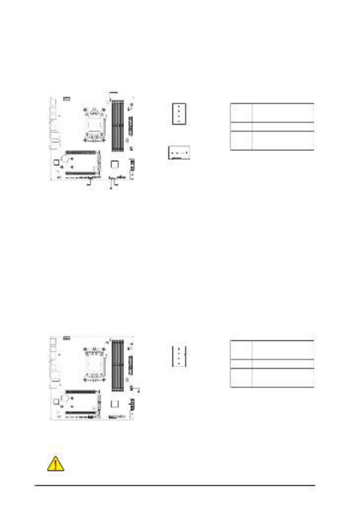
3/4) CPU_FAN/SYS_FAN1/2/3 (Fan Headers)
All fan headers on this motherboard are 4-pin. Most fan headers possess a foolproof insertion design.
When connecting a fan cable, be sure to connect it in the correct orientation (the black connector wire is
the ground wire). The speed control function requires the use of a fan with fan speed control design. For
optimum heat dissipation, it is recommended that a system fan be installed inside the chassis.
CPU_FAN
1
1
1
SYS_FAN1/SYS_FAN2/
SYS_FAN3
Pin No. Denition
1 GND
2Voltage Speed Control
3Sense
4PWM Speed Control
5) FAN4_PUMP (System Fan/Water Cooling Pump Header)
The fan/pump header is 4-pin and possesses a foolproof insertion design. Most fan headers possess a
foolproof insertion design. When connecting a fan cable, be sure to connect it in the correct orientation
(the black connector wire is the ground wire). The speed control function requires the use of a fan with
fan speed control design. For optimum heat dissipation, it is recommended that a system fan be installed
inside the chassis. The header also provides speed control for a water cooling pump. Please navigate to
the "BIOS Setup" page of GIGABYTE's website and search for "Smart Fan 6" for more information.
Pin No. Denition
1 GND
2Voltage Speed Control
3Sense
4PWM Speed Control
SYS_FAN1 SYS_FAN3
SYS_FAN2
CPU_FAN
FAN4_PUMP
Product specificaties
| Merk: | Gigabyte |
| Categorie: | Moederbord |
| Model: | B840M AORUS ELITE WIFI6E |
Heb je hulp nodig?
Als je hulp nodig hebt met Gigabyte B840M AORUS ELITE WIFI6E stel dan hieronder een vraag en andere gebruikers zullen je antwoorden
Handleiding Moederbord Gigabyte

10 Maart 2025
11 Februari 2025
11 Februari 2025
11 Februari 2025
11 Februari 2025
11 Februari 2025
11 Februari 2025
11 Februari 2025
11 Februari 2025
11 Februari 2025
Handleiding Moederbord
- Moederbord Asus
- Moederbord Asrock
- Moederbord EPoX
- Moederbord Evga
- Moederbord MSI
- Moederbord Sharkoon
- Moederbord NZXT
- Moederbord Intel
- Moederbord Supermicro
- Moederbord ECS
- Moederbord Foxconn
- Moederbord Advantech
- Moederbord Elitegroup
- Moederbord Biostar
Nieuwste handleidingen voor Moederbord

8 April 2025
8 April 2025
3 April 2025
3 April 2025
3 April 2025
3 April 2025
2 April 2025
2 April 2025

29 Maart 2025
27 Maart 2025