Gigabyte GA-M56S-S3 Handleiding
Gigabyte
Moederbord
GA-M56S-S3
Lees hieronder de 📖 handleiding in het Nederlandse voor Gigabyte GA-M56S-S3 (96 pagina's) in de categorie Moederbord. Deze handleiding was nuttig voor 40 personen en werd door 2 gebruikers gemiddeld met 4.5 sterren beoordeeld
Pagina 1/96

GA-M56S-S3
AM2 socket motherboard for
AMD AthlonTM 64 FX processor/
AMD AthlonTM 64 X2 Dual-Core processor/
AMD AthlonTM 64 processor/AMD SempronTM processor
User's Manual
Rev. 1004
12ME-M56SS3-1004R

Motherboard
GA-M56S-S3
Jul. 10, 2007
Moth e rb o ar d
GA-M56S-S3
Jul. 10, 2007

Copyright
© 2007 GIGA-BYTE TECHNOLOGY CO., LTD. All rights reserved.
The trademarks mentioned in this manual are legally registered to their respective owners.
The logo is exclusively licensed to GIGABYTE UNITED INC. by GIGA-BYTE
TECHNOLOGY CO., LTD.
GIGABYTE UNITED INC. is designated by GIGA-BYTE TECHNOLOGY CO., LTD as the exclu-
sive global distributor of GIGABYTE branded motherboards.
Disclaimer
Information in this manual is protected by copyright laws and is the property of GIGABYTE.
Changes to the specifications and features in this manual may be made by GIGABYTE without prior
notice. No part of this manual may be reproduced, copied, translated, transmitted, or published in any
form or by any means without GIGABYTE's prior written permission.
Documentation Classifications
In order to assist in the use of this product, GIGABYTE provides the following types of documentations:
For quick set-up of the product, read the Quick Installation Guide included with the product.
For detailed product information, carefully read the User's Manual.
For instructions on how to use GIGABYTE's unique features, read or download the
information on/from the Support\Motherboard\Technology Guide page on our website.
For product-related information, check on our website at:
http://www.gigabyte.com.tw
Identifying Your Motherboard Revision
The revision number on your motherboard looks like this: "REV: X.X." For example, "REV: 1.0"
means the revision of the motherboard is 1.0. Check your motherboard revision before updating
motherboard BIOS, drivers, or when looking for technical information.
Example:

- 4 -
Table of Contents
Box Contents ................................................................................................................. 6
Optional Items................................................................................................................. 6
GA-M56S-S3 Motherboard Layout ................................................................................ 7
Block Diagram ................................................................................................................ 8
Chapter 1 Hardware Installation .................................................................................... 9
1-1 Installation Precautions ..................................................................................... 9
1-2 Product Specifications .................................................................................... 10
1-3 Installing the CPU and CPU Cooler .............................................................. 12
1-3-1 Installing the CPU ................................................................................................ 12
1-3-2 Installing the CPU Cooler ................................................................................... 14
1-4 Installing the Memory ..................................................................................... 15
1-4-1 Dual Channel Memory Configuration ................................................................ 15
1-4-2 Installing a Memory ............................................................................................. 16
1-5 Installing an Expansion Card ......................................................................... 17
1-6 Back Panel Connectors ................................................................................. 18
1-7 Internal Connectors ........................................................................................ 20
Chapter 2 BIOS Setup................................................................................................. 31
2-1 Startup Screen ................................................................................................ 32
2-2 The Main Menu .............................................................................................. 33
2-3 Standard CMOS Features ............................................................................. 35
2-4 Advanced BIOS Features .............................................................................. 37
2-5 Integrated Peripherals ..................................................................................... 39
2-6 Power Management Setup ............................................................................. 44
2-7 PnP/PCI Configurations ................................................................................. 46
2-8 PC Health Status ........................................................................................... 47
2-9 MB Intelligent Tweaker(M.I.T.) ....................................................................... 49
2-10 Load Fail-Safe Defaults ................................................................................... 51
2-11 Load Optimized Defaults ................................................................................. 51
2-12 Set Supervisor/User Password ..................................................................... 52
2-13 Save & Exit Setup ......................................................................................... 53
2-14 Exit Without Saving ....................................................................................... 53

- 5 -
Chapter 3 Drivers Installation ...................................................................................... 55
3-1 Installing Chipset Drivers ............................................................................... 55
3-2 Software Applications ..................................................................................... 56
3-3 Driver CD Information .................................................................................... 56
3-4 Hardware Information ..................................................................................... 57
3-5 Contact Us ..................................................................................................... 57
Chapter 4 Unique Features ......................................................................................... 59
4-1 Xpress Recovery2 ......................................................................................... 59
4-2 BIOS Update Utilities ..................................................................................... 64
4-2-1 Updating the BIOS with the Q-Flash Utility ...................................................... 64
4-2-2 Updating the BIOS with the @BIOS Utility ....................................................... 67
4-3 EasyTune 5 .................................................................................................... 69
4-4 Windows Vista ReadyBoost ........................................................................... 70
Chapter 5 Appendix .................................................................................................... 71
5-1 Configuring SATA Hard Drive(s) .................................................................... 71
5-1-1 Configuring the Onboard SATA Controller ......................................................... 71
5-1-2 Making a SATA RAID/AHCI Driver Diskette ..................................................... 76
5-1-3 Installing the SATA RAID/AHCI Driver and Operating System ...................... 77
5-2 Configuring Audio Input and Output ................................................................. 82
5-2-1 Configuring 2/4/5.1/7.1-Channel Audio ............................................................ 82
5-2-2 Installing the S/PDIF In Cable (Optional) ........................................................... 84
5-2-3 Configuring Microphone Recording ................................................................... 86
5-2-4 Using the Sound Recorder ................................................................................. 88
5-3 Troubleshooting ............................................................................................... 89
5-3-1 Frequently Asked Questions ............................................................................. 89
5-3-2 Troubleshooting Procedure ................................................................................ 90
Regulatory Statements ................................................................................................. 92

- 6 -
Box Contents
GA-M56S-S3 motherboard
Motherboard Driver Disk
User's Manual
Quick Installation Guide
One IDE cable and one floppy disk drive cable
Two SATA 3Gb/s cables
I/O Shield
The box contents above are for reference only and the actual items shall depend on product package you obtain.
The box contents are subject to change without notice.
Optional Items
2-port USB 2.0 bracket (Part No. 12CR1-1UB030-51R)
2-port IEEE 1394a bracket (Part No. 12CF1-1IE008-01R)
S/PDIF in cable (Part No. 12CR1-1SPDIN-01R)
SATA power cable (Part No. 12CF1-1SERPW-01R)

- 7 -
GA-M56S-S3 Motherboard Layout
KB_MS
Socket AM2
GA-M56S-S3
USB
LAN
CD_IN
F_AUDIO
AUDIO
IT8716
SPDIF_I
CODEC
LPT
USB
1394
COMA
RTL8211BL
PCI1
CI
PCI2
PCI3
PCI4
BIOS
FDD
PCIE_16
PCIE_1
PCIE_2
SYS_FAN
F2_1394F1_1394
TSB43AB23
F_PANEL
PWR_LED
F_USB1
SATAII1
SATAII2SATAII3
F_USB2
F_USB3
DDRII_1
DDRII_2
DDRII_3
DDRII_4
BATTERY
nVIDIA
®
nForce 560
SATAII0 ATX
IDE
ATX_12V
CLR_CMOS
CPU_FAN
COAXIAL
OPTICAL
SPDIF_O

- 8 -
Block Diagram
AMD
Socket AM2
CPU
CPU CLK+/-(200 MHz)
Hyper Transport Bus
4 PCI
PCI Bus
2 PCI Express x1
PCI Express Bus
nVIDIA®
nForce 560
3 IEEE 1394a
TSB43AB23
DDR2 800/667/533 MHz DIMM
Dual Channel Memory
4 SATA 3Gb/s
10 USB
Ports
Line-Out
MIC
CODEC
Line-In
SPDIF In
SPDIF Out
Side Speaker Out
Center/Subwoofer Speaker Out
Surround Speaker Out
ATA-133/100/66/33
IDE Channel
PCIe CLK
(100 MHz)
LPC BUS
Floppy
LPT Port
PS/2 KB/Mouse
LAN
RJ45
RTL
8211BL
IT8716
x 1
BIOS
x 1
PCI Express x16
COM Port
PCIe CLK
(100 MHz)
PCI CLK
(33 MHz)

Hardware Installation- 9 -
English
Chapter 1 Hardware Installation
1-1 Installation Precautions
The motherboard contains numerous delicate electronic circuits and components which can become
damaged as a result of electrostatic discharge (ESD). Prior to installation, carefully read the user's
manual and follow these procedures:
•Prior to installation, do not remove or break motherboard S/N (Serial Number) sticker or
warranty sticker provided by your dealer. These stickers are required for warranty validation.
•Always remove the AC power by unplugging the power cord from the power outlet before
installing or removing the motherboard or other hardware components.
•When connecting hardware components to the internal connectors on the motherboard,
make sure they are connected tightly and securely.
•When handling the motherboard, avoid touching any metal leads or connectors.
•It is best to wear an electrostatic discharge (ESD) wrist strap when handling electronic
components such as a motherboard, CPU or memory. If you do not have an ESD wrist strap,
keep your hands dry and first touch a metal object to eliminate static electricity.
•Prior to installing the motherboard, please have it on top of an antistatic pad or within an
electrostatic shielding container.
•Before unplugging the power supply cable from the motherboard, make sure the power supply
has been turned off.
•Before turning on the power, make sure the power supply voltage has been set according to
the local voltage standard.
•Before using the product, please verify that all cables and power connectors of your hardware
components are connected.
•To prevent damage to the motherboard, do not allow screws to come in contact with the
motherboard circuit or its components.
•Make sure there are no leftover screws or metal components placed on the motherboard or
within the computer casing.
•Do not place the computer system on an uneven surface
.
•Do not place the computer system in a high-temperature environment.
•Turning on the computer power during the installation process can lead to damage to system
components as well as physical harm to the user.
•If you are uncertain about any installation steps or have a problem related to the use of the
product, please consult a certified computer technician.

GA-M56S-S3 Motherboard - 10 -
English
1-2 Product Specifications
CPU Support for Socket AM2 processors:
AMD AthlonTM 64 FX processor/AMD AthlonTM 64 X2 Dual-Core processor/
AMD AthlonTM 64 processor/AMD SempronTM processor
(Go to GIGABYTE's website for the latest CPU support list.)
Front Side Bus 2000 MHz FSB
Chipset nVIDIA® nForce 560 Chipset
Memory 4 x 1.8V DDR2 DIMM sockets supporting up to 16 GB of system memory (Note 1)
Dual channel memory architecture
Support for DDR2 800/667/533 MHz memory modules
(Go to GIGABYTE's website for the latest memory support list.)
Audio Realtek ALC888 codec
High Definition Audio
2/4/5.1/7.1-channel
Support for S/PDIF In/Out
Support for CD In
LAN Realtek 8211BL chip (10/100/1000 Mbit)
Expansion Slots 1 x PCI Express x16 slot
2 x PCI Express p10-x1 slots
4 x PCI slots
Storage Interface Chipset:
- 1 x IDE connector supporting ATA-133/100/66/33 and up to 2 IDE
devices
- 4 x SATA 3Gb/s connectors supporting up to 4 SATA 3Gb/s devices
- Support for SATA RAID 0, RAID 1, RAID 0+1, and RAID 5
iTE IT8716 chip:
- 1 x floppy disk drive connector supporting up to 1 floppy disk drive
IEEE 1394 T.I. TSB43AB23 chip
Up to 3 IEEE 1394a ports (1 on the back panel, 2 via the IEEE 1394 bracket
connected to the internal IEEE 1394 headers)
USB Integrated in the Chipset
Up to 10 USB 2.0/1.1 ports (4 on the back panel, 6 via the USB brackets
connected to the internal USB headers)
Internal Connectors 1 x 24-pin ATX main power connector
1 x 4-pin ATX 12V power connector
1 x floppy disk drive connector
1 x IDE connector
4 x SATA 3Gb/s connectors
1 x CPU fan header
1 x system fan header
1 x front panel header
1 x front panel audio header
1 x CD In connector

Hardware Installation- 11 -
English
Internal Connectors 1 x S/PDIF In header
1 x S/PDIF Out header
3 x USB 2.0/1.1 headers
2 x IEEE 1394a headers
1 x chassis intrusion header
1 x power LED header
Back Panel 1 x PS/2 keyboard port
Connectors 1 x PS/2 mouse port
1 x parallel port
1 x coaxial S/PDIF Out connector
1 x optical S/PDIF Out connector
1 x serial port
4 x USB 2.0/1.1 ports
1 x IEEE 1394a port
1 x RJ-45 port
6 x audio jacks (Center/Subwoofer Speaker Out/Rear Speaker Out/Side
Speaker Out/Line In/Line Out/Microphone)
I/O Controller iTE IT8716 chip
Hardware Monitor System voltage detection
CPU/System temperature detection
CPU/System fan speed detection
CPU/System overheating warning
CPU/System fan fail warning
CPU/System fan speed control
BIOS 1 x 4 Mbit flash
Use of licensed AWARD BIOS
PnP 1.0a, DMI 2.0, SM BIOS 2.4, ACPI 1.0b
Unique Features Support for @BIOS
Support for Download Center
Support for Q-Flash
Support for EasyTune (Note 2)
Support for Xpress Install
Support for Xpress Recovery2
Support for Virtual Dual BIOS
Bundled Software Norton Internet Security (OEM version)
Operating System Support for Microsoft®
Windows ® Vista/XP/2000
(Go to GIGABYTE's website for operating system support information.)
Form Factor ATX Form Factor; 30.5cm x 21.4cm
(Note 1) Based on standard PC architecture, a certain amount of memory is reserved for system usage
and therefore the actual memory size is less than the stated amount. For example, 4 GB of
memory size will instead be shown as 3.xx GB during system startup.
(Note 2) Available functions in Easytune may differ by motherboard model.

GA-M56S-S3 Motherboard - 12 -
English
1-3-1 Installing the CPU
A. Locate the pin one (denoted by a small triangle) of the CPU socket and the CPU.
AM2 CPU
AM2 CPU Socket
A Small Triangle Mark
Denotes Pin One o f the
Socket
A Small Triangle Marking
Denotes CPU Pin One
1-3 Installing the CPU and CPU Cooler
Read the following guidelines before you begin to install the CPU:
•Make sure that the motherboard supports the CPU.
(Go to GIGABYTE's website for the latest CPU support list.)
•Always turn off the computer and unplug the power cord from the power outlet before
installing the CPU to prevent hardware damage.
•Locate the pin one of the CPU. The CPU cannot be inserted if oriented incorrectly.
•Apply an even and thin layer of thermal grease on the surface of the CPU.
•Do not turn on the computer if the CPU cooler is not installed, otherwise overheating and
damage of the CPU may occur.
•Set the CPU host frequency in accordance with the CPU specifications. It is not recom-
mended that the system bus frequency be set beyond hardware specifications since it
does not meet the standard requirements for the peripherals. If you wish to set the fre-
quency beyond the standard specifications, please do so according to your hardware
specifications including the CPU, graphics card, memory, hard drive, etc.

Hardware Installation- 13 -
English
Step 2:
Align the CPU pin one (small triangle marking)
with the triangle mark on the CPU socket and
gently insert the CPU into the socket. Make
sure that the CPU pins fit perfectly into their
holes. Once the CPU is positioned into its
socket, place one finger down on the middle of
the CPU, lowering the locking lever and latch-
ing it into the fully locked position.
Step 1:
Completely lift up the CPU socket locking lever.
CPU Socket Locking
Lever
Do not force the CPU into the CPU socket. The CPU cannot fit in if oriented incorrectly. Adjust
the CPU orientation if this occurs.
B. Follow the steps below to correctly install the CPU into the motherboard CPU socket.
Before installing the CPU, make sure to turn off the computer and unplug the power
cord from the power outlet to prevent damage to the CPU.

GA-M56S-S3 Motherboard - 14 -
English
Use extreme care when removing the CPU cooler because the thermal grease/tape between
the CPU cooler and CPU may adhere to the CPU. Inadequately removing the CPU cooler
may damage the CPU.
1-3-2 Installing the CPU Cooler
Follow the steps below to correctly install the CPU cooler on the CPU. (The following procedure uses
the GIGABYTE cooler as the example.)
Step 1:
Apply an even and thin layer of thermal grease
on the surface of the installed CPU.
Step 2:
Place the CPU cooler on the CPU.
Step 4:
Turn the cam handle from the left side to the
right side (as the picture above shows) to lock
into place. (Refer to your CPU cooler installa-
tion manual for instructions on installing the
cooler.)
Step 3:
Hook the CPU cooler clip to the mounting lug on
one side of the retention frame. On the other side,
push straight down on the the CPU cooler clip to
hook it to the mounting lug on the retention frame.
Step 5:
Finally, attach the power connector of the CPU
cooler to the CPU fan header (CPU_FAN) on
the motherboard.

Hardware Installation- 15 -
English
DDRII_1
DDRII_2
DDRII_3
If two memory modules are to be installed, it is recom-
mended that you install them in the DDRII_1 and DDRII_2
sockets.
1-4 Installing the Memory
Two Modules
Four Modules
DDRII_1 DDRII_2 DDRII_3 DDRII_4
DS/SS DS/SS - - - -
- - - - DS/SS DS/SS
DS/SS DS/SS DS/SS DS/SS
Dual Channel Memory Configurations Table
(SS=Single-Sided, DS=Double-Sided, "- -"=No Memory)
Read the following guidelines before you begin to install the memory:
•Make sure that the motherboard supports the memory. It is recommended that memory of
the same capacity, brand, speed, and chips be used.
(Go to GIGABYTE's website for the latest memory support list.)
•Always turn off the computer and unplug the power cord from the power outlet before
installing the memory to prevent hardware damage.
•Memory modules have a foolproof design. A memory module can be installed in only one
direction. If you are unable to insert the memory, switch the direction.
1-4-1 Dual Channel Memory Configuration
This motherboard provides four DDR2 memory sockets and supports Dual Channel
Technology. After the memory is installed, the BIOS will automatically detect the
specifications and capacity of the memory. Enabling Dual Channel memory mode
will double the original memory bandwidth.
The four DDR2 memory sockets are divided into two channels and each channel has two memory
sockets as following:
Channel 0: DDRII_1, DDRII_3
Channel 1: DDRII_2, DDRII_4
Due to CPU limitation, read the following guidelines before installing the memory in Dual Channel mode.
1. Dual Channel mode cannot be enabled if only one DDR2 memory module is installed.
2. When enabling Dual Channel mode with two or four memory modules, it is recommended that
memory of the same capacity, brand, speed, and chips be used and installed in the same
colored DDR2 sockets for optimum performance.
DDRII_4

GA-M56S-S3 Motherboard - 16 -
English
Notch
DDR2 DIMM
1-4-2 Installing a Memory
Before installing a memory module , make sure to turn off the computer and unplug
the power cord from the power outlet to prevent damage to the memory module.
DDR2 DIMMs are not compatible to DDR DIMMs. Be sure to install DDR2 DIMMs on
this motherboard.
Step 1:
Note the orientation of the memory module. Spread the retaining
clips at both ends of the memory socket. Place the memory
module on the socket. As indicated in the picture on the left,
place your fingers on the top edge of the memory, push down
on the memory and insert it vertically into the memory socket.
Step 2:
The clips at both ends of the socket will snap into place when
the memory module is securely inserted.
A DDR2 memory module has a notch, so it can only fit in one direction. Follow the steps below to
correctly install your memory modules in the memory sockets.

Hardware Installation- 17 -
English
1-5 Installing an Expansion Card
Read the following guidelines before you begin to install an expansion card:
•Make sure the motherboard supports the expansion card. Carefully read the manual that
came with your expansion card.
•Always turn off the computer and unplug the power cord from the power outlet before
installing an expansion card to prevent hardware damage.
Follow the steps below to correctly install your expansion card in the expansion slot.
1. Locate an expansion slot that supports your card. Remove the metal slot cover from the chassis back panel.
2. Align the card with the slot, and press down on the card until it is fully seated in the slot.
3. Make sure the metal contacts on the card are completely inserted into the slot.
4. Secure the card's metal bracket to the chassis back panel with a screw.
5. After installing all expansion cards, replace the chassis cover(s).
6. Turn on your computer. If necessary, go to BIOS Setup to make any required BIOS changes for
your expansion card(s).
7. Install the driver provided with the expansion card in your operating system.
PCI Express x16 Slot
PCI Express p17-x1 Slot
PCI Slot
Example: Installing and Removing a PCI Express x16 Graphics Card:
•Installing a Graphics Card:
Gently insert the graphics card into the PCI Ex-
press x16 slot. Make sure the white latch se-
curely locks the graphics card.
•Removing the Card:
Press the white latch at the end of the PCI Express x16 slot to release the
card and then pull the card straight up from the slot.

GA-M56S-S3 Motherboard - 18 -
English
1-6 Back Panel Connectors
PS/2 Keyboard and PS/2 Mouse Port
Use the upper port (green) to connect a PS/2 mouse and the lower port (purple) to connect a PS/2
keyboard.
Parallel Port
Use the parallel port to connect devices such as a printer, scanner and etc. The parallel port is also
called a printer port.
Coaxial S/PDIF Out Connector
This connector provides digital audio out to an external audio system that supports digital coaxial
audio. Before using this feature, ensure that your audio system provides a coaxial digital audio in
connector.
Optical S/PDIF Out Connector
This connector provides digital audio out to an external audio system that supports digital optical
audio. Before using this feature, ensure that your audio system provides an optical digital audio in
connector.
Serial Port
Use the serial port to connect devices such as a mouse, modem or other peripherals.
IEEE 1394a Port
The IEEE 1394 port supports the IEEE 1394a specification, featuring high speed, high bandwidth
and hotplug capabilities. Use this port for an IEEE 1394a device.
USB Port
The USB port supports the USB 2.0/1.1 specification. Use this port for USB devices such as an
USB keyboard/mouse, USB printer, USB flash drive and etc.
RJ-45 LAN Port
The Gigabit Ethernet LAN port provides Internet connection at up to 1 Gbps data rate. The following
describes the states of the LAN port LEDs.
•When removing the cable connected to a back panel connector, first remove the cable
from your device and then remove it from the motherboard.
•When removing the cable, pull it straight out from the connector. Do not rock it side to side
to prevent an electrical short inside the cable connector.
Activity LED
Connection/
Speed LED
LAN Port
Activity LED:
State Description
Blinking Data transmission or receiving is occurring
Off No data transmission or receiving is occurring
Connection/Speed LED:
State Description
Orange 1 Gpbs data rate
Green 100 Mpbs data rate
Off 10 Mpbs data rate

Hardware Installation- 19 -
English
Center/Subwoofer Speaker Out Jack (Orange)
Use this audio jack to connect center/subwoofer speakers in a 5.1/7.1-channel audio configuration.
Rear Speaker Out Jack (Black)
Use this audio jack to connect rear speakers in a 4/5.1/7.1-channel audio configuration.
Side Speaker Out Jack (Gray)
Use this audio jack to connect side speakers in a 7.1-channel audio configuration.
Line In Jack (Blue)
The default line in jack. Use this audio jack for line in devices such as an optical drive, walkman, etc.
Line Out Jack (Green)
The default line out jack. Use this audio jack for a headphone or 2-channel speaker. This jack can
be used to connect front speakers in a 4/5.1/7.1-channel audio configuration.
Mic In Jack (Pink)
The default Mic in jack. Microphones must be connected to this jack.
In addition to the default speakers settings, the ~ audio jacks can be reconfigured to
perform different functions via the audio software. Only microphones still MUST be
connected to the default Mic in jack ( ). Refer to the instructions on setting up a 2/4/5.1/
7.1-channel audio configuration in Chapter 5, "Configuring 2/4/5.1/7.1-Channel Audio."

GA-M56S-S3 Motherboard - 20 -
English
1-7 Internal Connectors
Read the following guidelines before connecting external devices:
•First make sure your devices are compliant with the connectors you wish to connect.
•Before installing the devices, be sure to turn off the devices and your computer. Unplug the
power cord from the power outlet to prevent damage to the devices.
•After installing the device and before turning on the computer, make sure the device cable
has been securely attached to the connector on the motherboard.
2
1
4 10
9
5
15
6
3
7
8
11
12
13
17
16
18
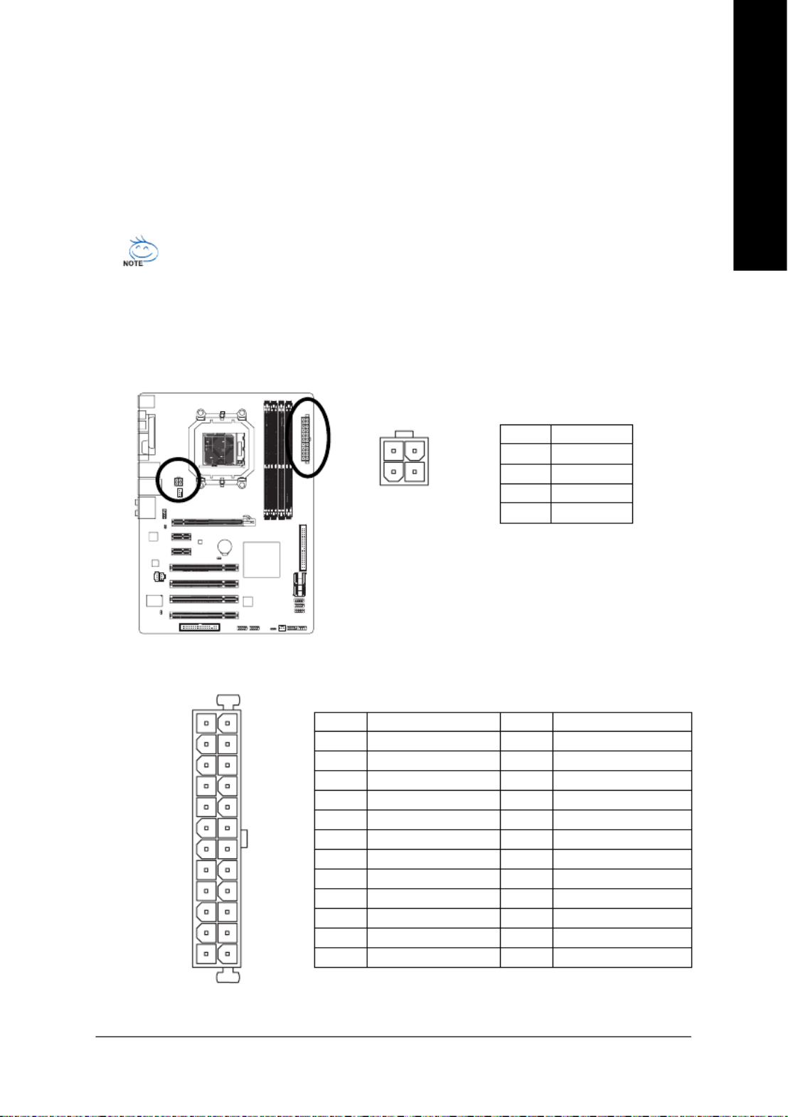
1) ATX_12V
2) ATX
3) CPU_FAN
4) SYS_FAN
5) FDD
6) IDE
7) SATAII0 / 1 / 2 / 3
8) PWR_LED
9) BATTERY
10) F_PANEL
11) F_AUDIO
12) CD_IN
13) SPDIF_I
14) SPDIF_O
15) F_USB1 / F_USB2 / F_USB3
16) F1_1394 / F2_1394
17) C I
18) CLR_CMOS
14
Hardware Installation- 21 -
English
131
24
12
ATX_12V :
ATX_12V
ATX
ATX :
Pin No. Definition
1 GND
2 GND
3 +12V
4 +12V
1
3
2
4
1/2) ATX_12V/ATX (2x2 12V Power Connector and 2x12 Main Power Connector)
With the use of the power connector, the power supply can supply enough stable power to all the
components on the motherboard. Before connecting the power connector, first make sure the
power supply is turned off and all devices are properly installed. The power connector possesses
a foolproof design. Connect the power supply cable to the power connector in the correct orientation.
The 12V power connector mainly supplies power to the CPU. If the 12V power connector is not
connected, the computer will not start.
•To meet expansion requirements, it is recommended that a power supply that can withstand
high power consumption be used (400W or greater). If a power supply is used that does not
provide the required power, the result can lead to an unstable or unbootable system.
•The main power connector is compatible with power supplies with 2x10 power connectors.
When using a 2x12 power supply, remove the protective cover from the main power
connector on the motherboard. Do not insert the power supply cable into pins under the
protective cover when using a 2x10 power supply.
Pin No. Definition
13 3.3V
14 -12V
15 GND
16 PS_ON(soft On/Off)
17 GND
18 GND
19 GND
20 -5V
21 +5V
22 +5V
23 +5V (Only for 2x12-pin ATX)
24 GND (Only for 2x12-pin ATX)
Pin No. Definition
1 3.3V
2 3.3V
3 GND
4 +5V
5 GND
6 +5V
7 GND
8 Power Good
9 5V SB(stand by +5V)
10 +12V
11 +12V (Only for 2x12-pin ATX)
12 3.3V (Only for 2x12-pin ATX)

GA-M56S-S3 Motherboard - 22 -
English
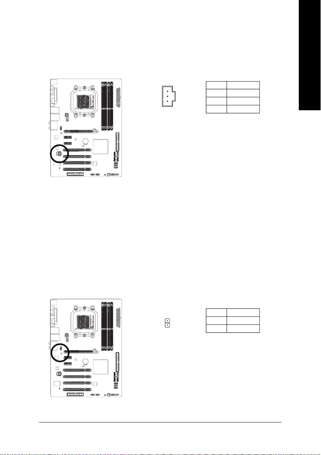
3/4) CPU_FAN/SYS_FAN (Fan Headers)
The motherboard has a 4-pin CPU fan header (CPU_FAN) and a 3-pin system fan header
(SYS_FAN). Each fan header supplies a +12V power voltage and possesses a foolproof insertion
design. When connecting a fan cable, be sure to connect it in the correct orientation. Most fans are
designed with color-coded power connector wires. A red power connector wire indicates a
positive connection and requires a +12V voltage. The black connector wire is the ground wire. The
motherboard supports CPU/system fan speed control, which requires the use of a CPU/system
fan with fan speed control design. For optimum heat dissipation, it is recommended that a system
fan be installed inside the chassis.
Pin No. Definition
1 GND
2 +12V
3 Sense
4 Speed Control
CPU_FAN :
Pin No. Definition
1 GND
2 +12V
3 Sense
SYS_FAN :
•Be sure to connect fan cables to the fan headers to prevent your CPU and system from
overheating. Overheating may result in damage to the CPU or the system may hang.
•These fan headers are not configuration jumper blocks. Do not place a jumper cap on the
headers.
5) FDD (Floppy Disk Drive Connector)
This connector is used to connect a floppy disk drive. The types of floppy disk drives supported
are: 360 KB, 720 KB, 1.2 MB, 1.44 MB, and 2.88 MB. Before connecting a floppy disk drive, locate
the foolproof groove on the connector.
1
1
SYS_FAN
CPU_FAN
1
2
33
34

GA-M56S-S3 Motherboard - 24 -
English
8) PWR_LED (System Power LED Header)
This header can be used to connect a system power LED on the chassis to indicate system power
status. The LED is on when the system is operating. The LED keeps blinking when the system is
in S1 sleep state. The LED is off when the system is in S3/S4 sleep state or powered off (S5).
Pin No. Definition
1 MPD+
2 MPD-
3 MPD-
9) BATTERY
The battery provides power to keep the values (such as BIOS configurations, date, and time
information) in the CMOS when the computer is turned off. Replace the battery when the battery
voltage drops to a low level, or the CMOS values may not be accurate or may be lost.
1
•Always turn off your computer and unplug the power cord before replacing the battery.
•Replace the battery with an equivalent one. Danger of explosion if the battery is replaced
with an incorrect model.
•Contact the place of purchase or local dealer if you are not able to replace the battery by
yourself or uncertain about the battery model.
•When installing the battery, note the orientation of the positive side (+) and the negative
side (-) of the battery (the positive side should face up).
•Used batteries must be handled in accordance with local environmental regulations.
You may clear the CMOS values by removing the battery:
1. Turn off your computer and unplug the power cord.
2. Gently remove the battery from the battery holder and wait for one minute.
(Or use a metal object like a screwdriver to touch the positive and
negative terminals of the battery holder, making them short for 5 seconds.)
3. Replace the battery.
4. Plug in the power cord and restart your computer.
System Status LED
S0 On
S1 Blinking
S3/S4/S5 Off

Hardware Installation- 25 -
English
10) F_PANEL (Front Panel Header)
Connect the power switch, reset switch, speaker and system status indicator on the chassis front
panel to this header according to the pin assignments below. Note the positive and negative pins
before connecting the cables.
•PW (Power Switch, Red):
Connects to the power switch on the chassis front panel. You may configure the way to turn off
your system using the power switch (refer to Chapter 2, "BIOS Setup," "Power Management
Setup," for more information).
•SPEAK (Speaker, Orange):
Connects to the speaker on the chassis front panel. The system reports system startup status
by issuing a beep code. One single short beep will be heard if no problem is detected at system
startup. If a problem is detected, the BIOS may issue beeps in different patterns to indicate the
problem. Refer to Chapter 5, "Troubleshooting," for information about beep codes.
•HD (IDE Hard Drive Activity LED, Blue)
Connects to the hard drive activity LED on the chassis front panel. The LED is on when the hard
drive is reading or writing data.
•RES (Reset Switch, Green):
Connects to the reset switch on the chassis front panel. Press the reset switch to restart the
computer if the computer freezes and fails to perform a normal restart.
•NC (Purple):
No connection
1
2
19
20
HD-
HD+
RES+
RES-
NC
SPEAK-
MSG-
MSG+
PW- PW+
Message/Power/
Sleep LED
Speaker
Connector
SPEAK+
Power
Switch
IDE Hard Disk
Active LED
Reset
Switch
System Status LED
S0 On
S1 Blinking
S3/S4/S5 Off
•MSG (Message/Power/Sleep LED, Yellow):
Connects to the power status indicator on the chassis front panel. The
LED is on when the system is operating. The LED keeps blinking when
the system is in S1 sleep state. The LED is off when the system is in
S3/S4 sleep state or powered off (S5).
The front panel design may differ by chassis. A front panel module mainly consists of
power switch, reset switch, power LED, hard drive activity LED, speaker and etc. When
connecting your chassis front panel module to this header, make sure the wire assign-
ments and the pin assignments are matched correctly.

GA-M56S-S3 Motherboard - 26 -
English
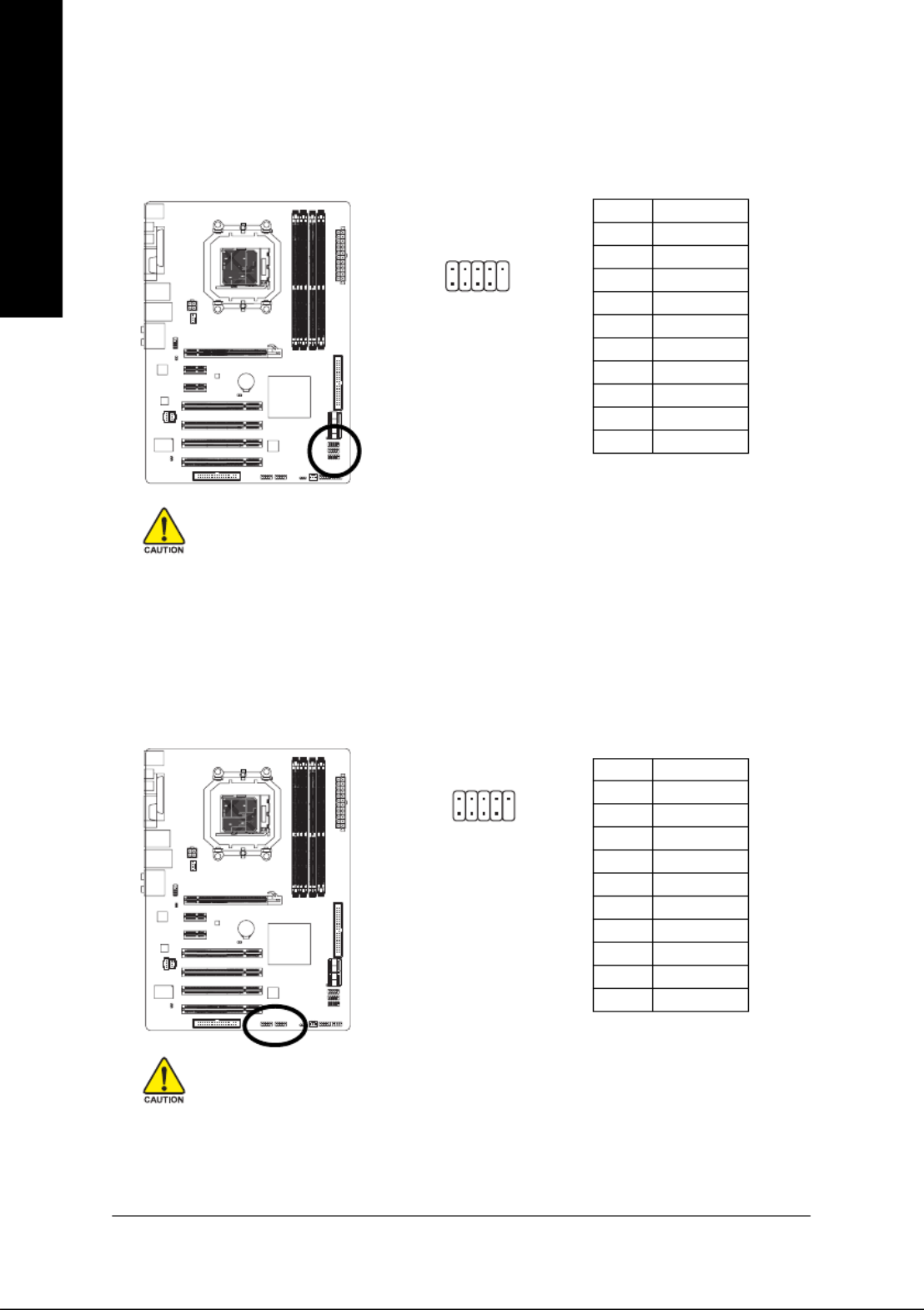
11) F_AUDIO (Front Panel Audio Header)
The front panel audio header supports Intel High Definition audio (HD) and AC'97 audio. You may
connect your chassis front panel audio module to this header. Make sure the wire assignments of
the module connector match the pin assignments of the motherboard header. Incorrect connection
between the module connector and the motherboard header will make the device unable to work
or even damage it.
12) CD_IN (CD In Connector)
You may connect the audio cable that came with your optical drive to the header.
Pin No. Definition
1 CD-L
2 GND
3 GND
4 CD-R
For AC'97 Front Panel Audio:
Pin No. Definition
1 MIC2_L
2 GND
3 MIC2_R
4 -ACZ_DET
5 LINE2_R
6 FSENSE1
7 FAUDIO_JD
8 No Pin
9 LINE2_L
10 FSENSE2
For HD Front Panel Audio:
1
•The front panel audio header supports HD audio by default. If your chassis provides an
AC'97 front panel audio module, refer to the instructions on how to activate AC'97 functioninality
via the audio software in Chapter 5, "Configuring 2/4/5.1/7.1-Channel Audio."
•Audio signals will be present on both of the front and back panel audio connections
simultaneously. If you want to mute the back panel audio (only supported when using an HD
front panel audio module), refer to Chapter 5, "Configuring 2/4/5.1/7.1-Channel Audio."
•Some chassis provide a front panel audio module that has separated connectors on each
wire instead of a single plug. For information about connecting the front panel audio
module that has different wire assignments, please contact the chassis manufacturer.
Pin No. Definition
1 MIC
2 GND
3 MIC Power
4 NC
5 Line Out (R)
6 NC
7 NC
8 No Pin
9 Line Out (L)
10 NC
10 9
2 1
Hardware Installation- 27 -
English
13) SPDIF_I (S/PDIF In Header)
This header supports digital S/PDIF in and can connect to an audio device that supports digital
audio out via an optional S/PDIF in cable. For purchasing the optional S/PDIF in cable, please
contact the local dealer.
Pin No. Definition
1 Power
2 SPDIFI
3 GND
1
Pin No. Definition
1 SPDIFO
2 GND
1
14) SPDIF_O (S/PDIF Out Header)
This header supports digital S/PDIF out and connects a S/PDIF digital audio cable (provided by
expansion cards) for digital audio output from your motherboard to certain expansion cards like
graphics cards and sound cards. For example, some graphics cards may require you to use a
S/PDIF digital audio cable for digital audio output from your motherboard to your graphics card if
you wish to connect an HDMI display to the graphics card and have digital audio output from the
HDMI display at the same time. For information about connecting the S/PDIF digital audio cable,
carefully read the manual for your expansion card.
GA-M56S-S3 Motherboard - 28 -
English
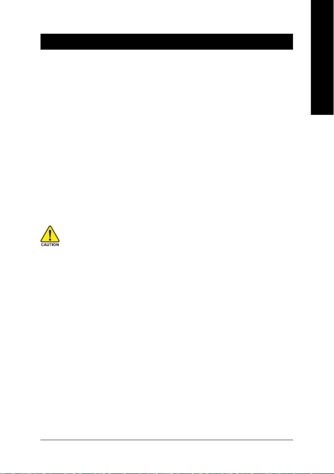
15) F_USB1/F_USB2/F_USB3 (USB Headers, Yellow)
The headers conform to USB 2.0/1.1 specification. Each USB header can provide two USB ports
via an optional USB bracket. For purchasing the optional USB bracket, please contact the local
dealer.
Pin No. Definition
1 Power (5V)
2 Power (5V)
3 USB DX-
4 USB DY-
5 USB DX+
6 USB DY+
7 GND
8 GND
9 No Pin
10 NC
•Do not plug the IEEE 1394 bracket (2x5-pin) cable into the USB header.
•Prior to installing the USB bracket, be sure to turn off your computer and unplug the
power cord from the power outlet to prevent damage to the USB bracket.
1 9
102
16) F1_1394/F2_1394 (IEEE 1394a Headers, Gray)
The headers conform to IEEE 1394a specification. Each IEEE 1394a header can provide one IEEE
1394a port via an optional IEEE 1394a bracket. For purchasing the optional IEEE 1394a bracket,
please contact the local dealer.
19
210
Pin No. Definition
1 TPA+
2 TPA-
3 GND
4 GND
5 TPB+
6 TPB-
7 Power (12V)
8 Power (12V)
9 No Pin
10 GND
•Do not plug the USB bracket cable into the IEEE 1394a header.
•Prior to installing the IEEE 1394a bracket, be sure to turn off your computer and unplug
the power cord from the power outlet to prevent damage to the IEEE 1394a bracket.
•To connect an IEEE 1394a device, attach one end of the device cable to your computer
and then attach the other end of the cable to the IEEE 1394a device. Ensure that the cable
is securely connected.

Hardware Installation- 29 -
English
17) CI (Chassis Intrusion Header)
This motherboard provides a chassis detection feature that detects if the chassis cover has been
removed. This function requires a chassis with chassis intrusion detection design.
Pin No. Definition
1 Signal
2 GND
1
Open: Normal
Short: Clear CMOS Values
18) CLR_CMOS (Clearing CMOS Jumper)
Use this jumper to clear the CMOS values (e.g. date information and BIOS configurations) and
reset the CMOS values to factory defaults. To clear the CMOS values, place a jumper cap on the
two pins to temporarily short the two pins or use a metal object like a screwdriver to touch the two
pins for a few seconds.
•Always turn off your computer and unplug the power cord from the power outlet before
clearing the CMOS values.
•After clearing the CMOS values and before turning on your computer, be sure to remove
the jumper cap from the jumper. Failure to do so may cause damage to the motherboard.
•After system restart, go to BIOS Setup to load factory defaults (select Load Optimized
Defaults) or manually configure the BIOS settings (refer to Chapter 2, "BIOS Setup," for
BIOS configurations).

GA-M56S-S3 Motherboard - 30 -
English
- 31 - BIOS Setup
English
Chapter 2 BIOS Setup
BIOS (Basic Input and Output System) records hardware parameters of the system in the CMOS on the
motherboard. Its major functions include conducting the Power-On Self-Test (POST) during system
startup, saving system parameters and loading operating system, etc. BIOS includes a BIOS Setup
program that allows the user to modify basic system configuration settings or to activate certain system
features. When the power is turned off, the battery on the motherboard supplies the necessary power
to the CMOS to keep the configuration values in the CMOS.
To access the BIOS Setup program, press the <Delete> key during the POST when the power is turned
on. To see more advanced BIOS Setup menu options, you can press <Ctrl> + <F1> in the main menu
of the BIOS Setup program.
To upgrade the BIOS, use either the GIGABYTE Q-Flash or @BIOS utility.
•Q-Flash allows the user to quickly and easily upgrade or back up BIOS without entering the
operating system.
•@BIOS is a Windows-based utility that searches and downloads the latest version of BIOS from the
Internet and updates the BIOS.
For instructions on using the Q-Flash and @BIOS utilities, refer to Chapter 4, "BIOS Update Utilities."
•Because BIOS flashing is potentially risky, if you do not encounter problems using the
current version of BIOS, it is recommended that you not flash the BIOS. To flash the BIOS,
do it with caution. Inadequate BIOS flashing may result in system malfunction.
•BIOS will emit a beep code during the POST. Refer to Chapter 5, "Troubleshooting," for the
beep codes description.
•It is recommended that you not alter the default settings (unless you need to) to prevent
system instability or other unexpected results. Inadequately altering the settings may result
in system's failure to boot. If this occurs, try to clear the CMOS values and reset the board
to default values. (Refer to the "Load Optimized Defaults" section in this chapter or introduc-
tions of the battery/clearing CMOS jumper in Chapter 1 for how to clear the CMOS values.)

GA-M56S-S3 Motherboard - 32 -
English
2-1 Startup Screen
The following screens may appear when the computer boots.
A. The LOGO Screen (Default)
<TAB>: POST Screen <DEL>: BIOS Setup/Q-Flash <F9>: XpressRecovery2 <F12>: Boot Menu
Function Keys
B. The POST Screen
Motherboard Model
BIOS Version
Function Keys
Award Modular BIOS v6.00PG, An Energy Star Ally
Copyright (C) 1984-2007, Award Software, Inc.
GA-M56S-S3 D1
.
.
.
.
<DEL>: BIOS Setup/Q-Flash <F9>: XpressRecovery2 <F12>: Boot Menu <End>: Qflash
06/22/2 0 0 7 - NF-MCP65-6A61LG01C-00
Function Keys:
<TAB> : POST Screen
Press the <Tab> key to show the BIOS POST screen. To show the BIOS POST screen at system
startup, refer to the instructions on the Full Screen LOGO Show item on page 38.
<DEL> : BIOS Setup/Q-Flash
Press the <Delete> key to enter BIOS Setup or to access the Q-Flash utility in BIOS Setup.
<F9> : Xpress Recovery2
If you have ever entered Xpress Recovery2 to back up hard drive data using the motherboard
driver disk, the <F9> key can be used for subsequent access to XpressRecovery2 during the
POST. For more information, refer to Chapter 4, "Xpress Recovery2."
<F12> : Boot Menu
Boot Menu allows you to set the first boot device without entering BIOS Setup. In Boot Menu, use
the up arrow key < > or the down arrow key< > to select the first boot device, then press <Enter>
to accept. To exit Boot Menu, press <Esc>. The system will directly boot from the device
configured in Boot Menu.
Note: The setting in Boot Menu is effective for one time only. After system restart, the device boot
order will still be based on BIOS Setup settings. You can access Boot Menu again to change the first
boot device setting as needed.
<End> : Q-Flash
Press the <End> key to access the Q-Flash utility directly without having to enter BIOS Setup first.
- 33 - BIOS Setup
English
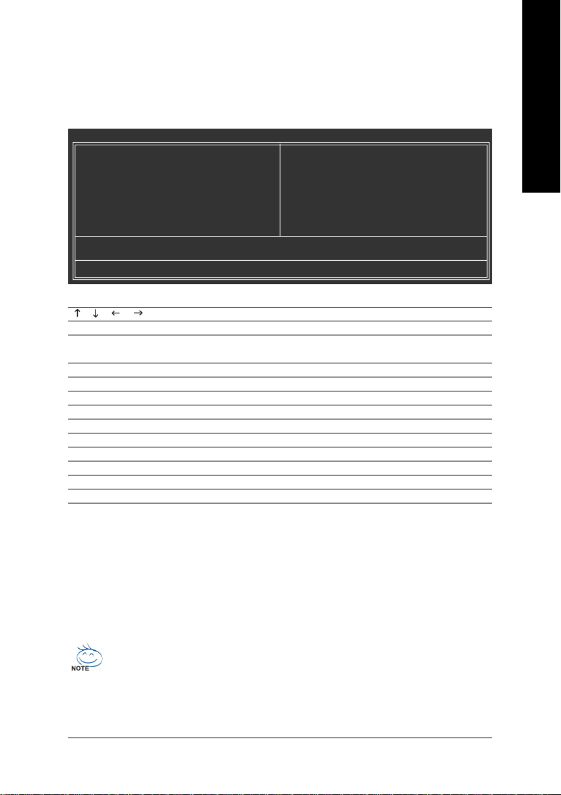
2-2 The Main Menu
Once you enter the BIOS Setup program, the Main Menu (as shown below) appears on the screen. Use
arrow keys to move among the items and press <Enter> to accept or enter a sub-menu.
(Sample BIOS Version: D1)
Main Menu Help
The onscreen description of a highlighted setup option is displayed on the bottom line of the Main Menu.
Submenu Help
While in a submenu, press <F1> to display a help screen (General Help) of function keys available for
the menu. Press <Esc> to exit the help screen. Help for each item is in the Item Help block on the right
side of the submenu.
BIOS Setup Program Function Keys
< >< >< >< > Move the selection bar to select an item
<Enter> Execute command or enter the submenu
<Esc> Main Menu: Exit the BIOS Setup program
Submenus: Exit current submenu
<Page Up> Increase the numeric value or make changes
<Page Down> Decrease the numeric value or make changes
<F1> Show descriptions of the function keys
<F2> Move cursor to the Item Help block on the right (submenus only)
<F5> Restore the previous BIOS settings for the current submenus
<F6> Load the Fail-Safe BIOS default settings for the current submenus
<F7> Load the Optimized BIOS default settings for the current submenus
<F8> Access the Q-Flash utility
<F9> Display system information
<F10> Save all the changes and exit the BIOS Setup program
•If you do not find the settings you want in the Main Menu or a submenu, press <Ctrl>+<F1>
to access more advanced options.
•When the system is not stable as usual, select the Load Optimized Defaults item to set
your system to its defaults.
•The BIOS Setup menus described in this chapter are for reference only and may differ by
BIOS version.
CMOS Setup Utility-Copyright (C) 1984-2007 Award Software
`Standard CMOS Features
`Advanced BIOS Features
`Integrated Peripherals
`Power Management Setup
`PnP/PCI Configurations
`PC Health Status
`MB Intelligent Tweaker(M.I.T.)
Load Fail-Safe Defaults
Load Optimized Defaults
Set Supervisor Password
Set User Password
Save & Exit Setup
Exit Without Saving
Esc: Quit KLJI: Select Item
F8: Q-Flash F10: Save & Exit Setup
Time, Date, Hard Disk Type...

GA-M56S-S3 Motherboard - 34 -
English
Standard CMOS Features
Use this menu to configure the system time and date, hard drive types, floppy disk drive types,
and the type of errors that stop the system boot, etc.
Advanced BIOS Features
Use this menu to configure the device boot order, advanced features available on the CPU, and
the primary display adapter.
Integrated Peripherals
Use this menu to configure all peripheral devices, such as IDE, SATA, USB, integrated audio, and
integrated LAN, etc.
Power Management Setup
Use this menu to configure all the power-saving functions.
PnP/PCI Configurations
Use this menu to configure the system's PCI & PnP resources.
PC Health Status
Use this menu to see information about autodetected system/CPU temperature, system voltage
and fan speed, etc.
MB Intelligent Tweaker(M.I.T.)
Use this menu to configure the clock, frequency and voltages of your CPU, memory, etc.
Load Fail-Safe Defaults
Fail-Safe defaults are factory settings for the most stable, minimal-performance system operations.
Load Optimized Defaults
Optimized defaults are factory settings for optimal-performance system operations.
Set Supervisor Password
Change, set, or disable password. It allows you to restrict access to the system and BIOS Setup.
A supervisor password allows you to make changes in BIOS Setup.
Set User Password
Change, set, or disable password. It allows you to restrict access to the system and BIOS Setup.
An user password only allows you to view the BIOS settings but not to make changes.
Save & Exit Setup
Save all the changes made in the BIOS Setup program to the CMOS and exit BIOS Setup.
(Pressing <F10> can also carry out this task.)
Exit Without Saving
Abandon all changes and the previous settings remain in effect. Pressing <Y> to the confirmation
message will exit BIOS Setup. (Pressing <Esc> can also carry out this task.)

- 35 - BIOS Setup
English
2-3 Standard CMOS Features
CMOS Setup Utility-Copyright (C) 1984-2007 Award Software
Standard CMOS Features
Date (mm:dd:yy) Fri, Jun 22 2007
Time (hh:mm:ss) 22:31:24
`IDE Channel 0 Master [None]
`IDE Channel 0 Slave [None]
`IDE Channel 2 Master [None]
`IDE Channel 2 Slave [None]
`IDE Channel 3 Master [None]
`IDE Channel 3 Slave [None]
Drive A [1.44M, 3.5"]
Floppy 3 Mode Support [Disabled]
Halt On [All, But Keyboard]
Base Memory 640K
Extended Memory 510M
KLJI: Move Enter: Select +/-/PU/PD: Value F10: Save ESC: Exit F1: General Help
F5: Previous Values F6: Fail-Safe Default F7: Optimized Defaults
Item Help
Menu Level`
Date
Sets the system date. The date format is week (read-only), month, date and year. Select the
desired field and use the up arrow or down arrow key to set the date.
Time
Sets the system time. For example, 1 p.m. is 13:0:0. Select the desired field and use the up arrow
or down arrow key to set the time.
IDE Channel 0 Master/Slave
IDE HDD Auto-Detection
Press <Enter> to autodetect the parameters of the IDE/SATA device on this channel.
IDE Channel 0 Master/Slave
Configure your IDE/SATA devices by using one of the three methods below:
• Auto Lets BIOS automatically detect IDE/SATA devices during the POST. (Default)
• None If no IDE/SATA devices are used, set this item to None so the system will
skip the detection of the device during the POST for faster system startup.
• Manual Allows you to manually enter the specifications of the hard drive when the
hard drive access mode is set to CHS.
Access Mode Sets the hard drive access mode. Options are: Auto (default), CHS, LBA,
Large.
IDE Channel 2/3 Master/Slave
IDE Auto-Detection
Press <Enter> to autodetect the parameters of the IDE/SATA device on this channel.
Extended IDE Drive
Configure your IDE/SATA devices by using one of the two methods below:
• Auto Lets BIOS automatically detect IDE/SATA devices during the POST. (Default)
• None If no IDE/SATA devices are used, set this item to None so the system will
skip the detection of the device during the POST for faster system startup.
Access Mode Sets the hard drive access mode. Options are: Auto (default), Large.

GA-M56S-S3 Motherboard - 36 -
English
The following fields display your hard drive specifications. If you wish to enter the parameters
manually, refer to the information on the hard drive.
Capacity Approximate capacity of the currently installed hard drive.
Cylinder Number of cylinders.
Head Number of heads.
Precomp Write precompensation cylinder.
Landing Zone Landing zone.
Sector Number of sectors.
Drive A
Allows you to selects the type of floppy disk drive installed in your system. If you do not install a
floppy disk drive, set this item to None. Options are: None, 360K/5.25", 1.2M/5.25", 720K/3.5",
1.44M/3.5", 2.88M/3.5".
Floppy 3 Mode Support
Allows you to specify whether the installed floppy disk drive is 3-mode floppy disk drive, a
Japanese standard floppy disk drive. Options are: Disabled (default), Drive A.
Halt on
Allows you to determine whether the system will stop for an error during the POST.
No Errors The system boot will not stop for any error.
All Errors Whenever the BIOS detects a non-fatal error the system boot will stop.
All, But Keyboard The system boot will not stop for a keyboard error but stop for all other
errors. (Default)
All, But Diskette The system boot will not stop for a floppy disk drive error but stop for all
other errors.
All, But Disk/Key The system boot will not stop for a keyboard or a floppy disk drive error but
it will stop for all other errors.
Memory
These fields are read-only and are determined by the BIOS POST.
Base Memory Also called conventional memory. Typically, 640 KB will be reserved for
the MS-DOS operating system.
Extended Memory The amount of extended memory.

- 37 - BIOS Setup
English
2-4 Advanced BIOS Features
AMD K8 Cool&Quiet control
Auto Lets the AMD Cool'n'Quiet driver dynamically adjust the CPU clock and VIA to
reduce heat output from your computer and its power consumption. (Default)
Disabled Disable this function.
Hard Disk Boot Priority
Specifies the sequence of loading the operating system from the installed hard drives. Use the up
or down arrow key to select a hard drive, then press the plus key <+> (or <PageUp>) or the minus
key <-> (or <PageDown>) to move it up or down on the list. Press <Esc> to exit this menu when
finished.
First/Second/Third Boot Device
Specifies the boot order from the available devices. Use the up or down arrow key to select a
device and press <Enter> to accept. Options are: Floppy, LS120, Hard Disk, CDROM, ZIP,
USB-FDD, USB-ZIP, USB-CDROM, USB-HDD, LAN, Disabled.
Password Check
Specifies whether a password is required every time the system boots, or only when you enter
BIOS Setup. After configuring this item, set the password(s) under the Set Supervisor/User
Password item in the BIOS Main Menu.
Setup A password is only required for entering the BIOS Setup program. (Default)
System A password is required for booting the system and for entering the BIOS Setup
program.
HDD S.M.A.R.T. Capability
Enables or disables the S.M.A.R.T. (Self Monitoring and Reporting Technology) capability of your
hard drive. This feature allows your system to report read/write errors of the hard drive and to
issue warnings when a third party hardware monitor utility is installed. (Default: Disabled)
CMOS Setup Utility-Copyright (C) 1984-2007 Award Software
Advanced BIOS Features
AMD K8 Cool&Quiet control [Auto]
`Hard Disk Boot Priority [Press Enter]
First Boot Device [Floppy]
Second Boot Device [Hard Disk]
Third Boot Device [CDROM]
Password Check [Setup]
HDD S.M.A.R.T. Capability [Disabled]
Away Mode [Disabled]
Full Screen LOGO Show [Enabled]
Init Display First [PEG]
KLJI: Move Enter: Select +/-/PU/PD: Value F10: Save ESC: Exit F1: General Help
F5: Previous Values F6: Fail-Safe Defaults F7: Optimized Defaults
Item Help
Menu Level`

GA-M56S-S3 Motherboard - 38 -
English
Away Mode
Enables or disables Away Mode in Windows XP Media Center operating system. Away Mode
allows the system to silently perform unattended tasks while in a low-power mode that appears off
(Default: Disabled)
Init Display First
Specifies the first initiation of the monitor display from the installed PCI graphics card or the
PCI Express graphics card.
PCI Slot Sets the PCI graphics card as the first display. (Default)
PEG Sets PCI Express graphics card as the first display.
Full Screen LOGO Show
Allows you to determine whether to display the GIGABYTE Logo at system startup. Disabled
displays normal POST message. (Default: Enabled)

- 39 - BIOS Setup
English
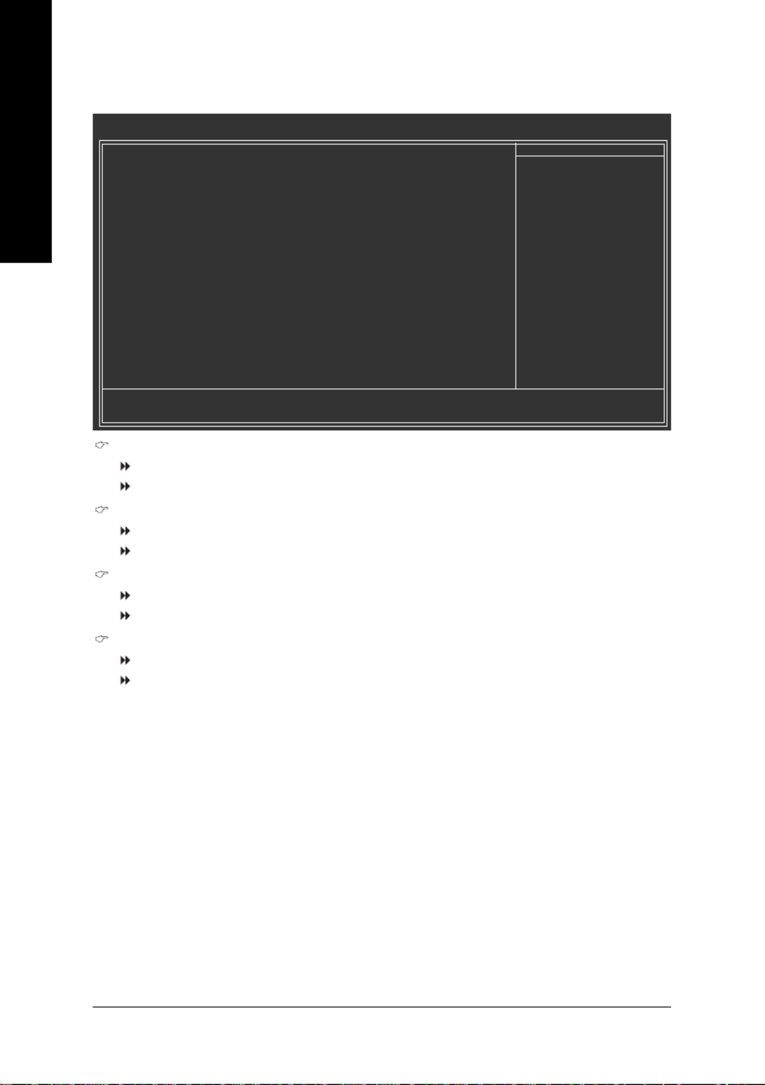
2-5 Integrated Peripherals
CMOS Setup Utility-Copyright (C) 1984-2007 Award Software
Integrated Peripherals
`Serial-ATA RAID Config [Press Enter]
On-Chip IDE Channel0 [Enabled]
IDE DMA tran sfer access [Enabled]
On-Chip MAC Lan [Auto]
NV Serial-ATA 1 [Enabled]
IDE Prefetch Mode [Enabled]
USB Memory Type [SHADOW]
Onchip SATA Mode [IDE]
Onboard Audio Function [Auto]
Onboard 1394 [Enabled]
`SMART LAN [Press Enter]
Onboard LAN Boot ROM [Disabled]
Onboard Serial Port 1 [3F8/IRQ4]
Onboard Parallel Port [378/IRQ7]
Parallel Port Mode [SPP]
x ECP Mode Use DMA 3
On-Chip USB [V1.1+V2.0]
USB Keyboard Support [Disabled]
USB Mouse Support [Disabled]
KLJI: Move Enter: Select +/-/PU/PD: Value F10: Save ESC: Exit F1: General Help
F5: Previous Values F6: Fail-Safe Defaults F7: Optimized Defaults
Item Help
Menu Level`
CMOS Setup Utility-Copyright (C) 1984-2007 Award Software
Integrated Peripherals
KLJI: Move Enter: Select +/-/PU/PD: Value F10: Save ESC: Exit F1: General Help
F5: Previous Values F6: Fail-Safe Defaults F7: Optimized Defaults
Item Help
Menu Level`
Legacy USB storage detect [Enabled]

GA-M56S-S3 Motherboard - 40 -
English
NV SATA Pri-Master RAID
Enables or disables RAID for the first SATA 3Gb/s connector (SATAII0). This item is configurable
only if the Onchip SATA Mode item is set to RAID. (Default: Enabled)
NV SATA Pri-Slave RAID
Enables or disables RAID for the second SATA 3Gb/s connector (SATAII1). This item is configurable
only if the Onchip SATA Mode item is set to RAID. (Default: Enabled)
NV SATA Sec-Master RAID
Enables or disables RAID for the third SATA 3Gb/s connector (SATAII2). This item is configurable
only if the Onchip SATA Mode item is set to RAID. (Default: Enabled)
NV SATA Sec-Slave RAID
Enables or disables RAID for the fourth SATA 3Gb/s connector (SATAII3). This item is configurable
only if the Onchip SATA Mode item is set to RAID. (Default: Enabled)
On-Chip IDE Channel0
Enables or disables the first integrated IDE controller. (Default: Enabled)
IDE DMA transfer access
Enables or disables DMA (Direct Memory Access) mode for the IDE device(s). Disabled turns off
DMA mode for the IDE device(s) and lets it operate in PIO (Programmed Input/Output) mode.
(Default: Enabled)
On-Chip MAC LAN
Enables or disables the onboard LAN function. (Default: Auto)
If you wish to install a 3rd party add-in network card instead of using the onboard LAN, set this item
to Disabled.
NV Serial-ATA 1
Enables or disables the integrated SATA controllers. (Default: Enabled)
IDE Prefetch Mode
Enables or disbales prefetch mode for the integrated IDE controller. Enabled activates the IDE
prefetch buffer to enhance hard drive performance. (Default: Enabled)
Serial-ATA RAID Config
CMOS Setup Utility-Copyright (C) 1984-2007 Award Software
Serial-ATA RAID Config
Item Help
Menu Level`
x NV SATA Pri-Master RAID Enabled
x NV SATA Pri-Slave RAID Enabled
x NV SATA Sec-Master RAID Enabled
x NV SATA Sec-Slave RAID Enabled
KLJI: Move Enter: Select +/-/PU/PD: Value F10: Save ESC: Exit F1: General Help
F5: Previous Values F6: Fail-Safe Defaults F7: Optimized Defaults

- 41 - BIOS Setup
English
USB Memory Type
Specifies the type of memory allocated for USB devices. Options are: SHADOW (default), Base
Memory (640K).
Onchip SATA Mode
Enables or disables RAID for the SATA controller integrated in the nVIDIA® nForce 560 chipset or
configures the SATA controller to AHCI mode.
IDE Disables RAID for the SATA controller and configures the SATA controller to
PATA mode. (Default)
AHCI Configures the SATA controller to AHCI mode. Advanced Host Controller
Interface (AHCI) is an interface specification that allows the storage driver to
enable advanced Serial ATA features such as Native Command Queuing and
hot plug.
RAID Enables RAID for the SATA controller.
Onboard Audio Function
Enables or disables the onboard audio function. (Default: Auto)
If you wish to install a 3rd party add-in audio card instead of using the onboard audio, set this item
to Disabled.
Onboard 1394
Enables or disables the onboard IEEE 1394 function. (Default: Enabled)
SMART LAN (LAN Cable Diagnostic Function)
This motherboard incorporates cable diagnostic feature designed to detect the status of the attached LAN
cable. This feature will detect cabling issue and report the approximate distance to the fault or short.
Refer to the following information for diagnosing your LAN cable:
When No LAN Cable Is Attached...
If no LAN cable is attached to the motherboard, the Status fields of all four pairs of wires will show
Open and the Length fields show 0.0m, as shown in the figure above.
CMOS Setup Utility-Copyright (C) 1984-2007 Award Software
SMART LAN
Item Help
Menu Level`
Start detecting at Port.....
Pair1-2 Status = Open / Length = 0.0m
Pair3-6 Status = Open / Length = 0.0m
Pair4-5 Status = Open / Length = 0.0m
Pair7-8 Status = Open / Length = 0.0m
KLJI: Move Enter: Select +/-/PU/PD: Value F10: Save ESC: Exit F1: General Help
F5: Previous Values F6: Fail-Safe Defaults F7: Optimized Defaults

GA-M56S-S3 Motherboard - 42 -
English
When LAN Cable Is Functioning Normally...
If no cable problem is detected on the LAN cable connected to a Gigabit hub or a 10/100 Mbps hub,
the following message will appear:
Link Detected Displays transmission speed
Cable Length Displays the approximate length of the attached LAN cable.
Note: The Gigabit hub will only operate at a speed of 10/100Mbps in MS-DOS mode; it will operate
at a normal speed of 10/100/1000Mbps in Windows mode or when the LAN Boot ROM is activated.
When a Cable Problem Occurs...
If a cable problem occurs on a specified pair of wires, the Status field will show Short and
thenlength shown will be the approximate distance to the fault or short.
Example: Pair1-2 Status = Short / Length = 1.6m
Explanation: A fault or short might occur at about 1.6m on Pair 1-2.
Note: Pair 4-5 and Pair 7-8 are not used in a 10/100 Mbps environment, so their Status fields will
show Open, and the length shown is the approximate length of the attached LAN cable.
Start detecting at Port.....
Link Detected --> 100Mbps
Cable Length= 30 m
Onboard LAN Boot ROM
Allows you to decide whether to activate the boot ROM integrated with the onboard LAN chip.
(Default: Disabled)
Onboard Serial Port 1
Enables or disables the first serial port and specifies its base I/O address and corresponding
interrupt. Options are: Auto, 3F8/IRQ4 (default), 2F8/IRQ3, 3E8/IRQ4, 2E8/IRQ3, Disabled.
Onboard Parallel Port
Enables or disables the onboard parallel port (LPT) and specifies its base I/O address and
corresponding interrupt. Options are: 378/IRQ7 (default), 278/IRQ5, 3BC/IRQ7, Disabled.
Parallel Port Mode
Selects an operating mode for the onboard parallel (LPT) port. Options are: SPP (Standard Parallel
Port)(default), EPP (Enhanced Parallel Port), ECP (Extended Capabilities Port), ECP+EPP.
ECP Mode Use DMA
Selects DMA channel for the LPT port in ECP mode. This item is configurable only if Parallel Port
Mode is set to ECP or ECP+EPP mode. Options are: 3 (default), 1.

- 43 - BIOS Setup
English
On-Chip USB Controller
Configures the integrated USB controller.
V1.1+V2.0 Enables the integrated USB 1.1 and USB 2.0 controllers. (Default)
V1.1 Enables only the integrated USB 1.1 controller.
Disabled Disables the integrated USB 1.1 and USB 2.0 controllers.
Disabled will turn off all of the USB functionalities below.
USB Keyboard Support
Allows USB keyboard to be used in MS-DOS. (Default: Disabled)
USB Mouse Support
Allows USB mouse to be used in MS-DOS. (Default: Disabled)
Legacy USB storage detect
Determines whether to detect USB storage devices, including USB flash drives and USB hard
drives during the POST. (Default: Enabled)

- 45 - BIOS Setup
English
USB Resume from Suspend
Allows the system to be awakened from ACPI S3 sleep state by a wake-up signal from the
installed USB device. (Default: Enabled)
Power On by Alarm
Determines whether to power on the system at a desired time. (Default: Disabled)
If enabled, set the date and time as following:
Day of Month Alarm : Turn on the system at a specific time on each day or on a specific day
in a month.
Time (hh: mm: ss) Alarm : Set the time at which the system will be powered on automatically.
Note: When using this function, avoid inadequate shutdown from the operating system or removal
of the AC power, or the settings may not be effective.
HPET Support (Note)
Enables or disables High Precision Event Timer (HPET) for Windows® Vista® operating system.
(Default: Enabled)
HPET Mode (Note)
Allows you to select the HPET mode for your Windows® Vista® operating system. Select 32-bit
mode when you install 32-bit Windows® Vista® ; select 64-bit mode when you install 64-bit
Windows® Vista ®. (Default: 32-bit mode)
Power On By Mouse
Allows the system to be turned on by a PS/2 mouse wake-up event.
Note: To use this function, you need an ATX power supply providing at least 1A on the 5VSB lead.
Disabled Disables this function. (Default)
Double Click Double click on left button on the PS/2 mouse to turn on the system.
Power On By Keyboard
Allows the system to be turned on by a PS/2 keyboard wake-up event.
Note: you need an ATX power supply providing at least 1A on the 5VSB lead.
Disabled Disables this function. (Default)
Password Set a password with 1~5 characters to turn on the system.
Any Key Press any key on the keyboard to turn on the system.
Keyboard 98 Press POWER button on the Windows 98 keyboard to turn on the system.
KB Power ON Password
Set the password when Power On by Keyboard is set to Password. Press <Enter> on this item
and set a password with up to 5 characters and then press <Enter> to accept. To turn on the
system, enter the password and press <Enter>.
Note: To cancel the password, press <Enter> on this item. When prompted for the password, press
<Enter> again without entering the password to clear the password settings.
AC Back Function
Determines the state of the system after the return of power from an AC power loss.
Soft-Off The system stays off upon the return of the AC power. (Default)
Full-On The system is turned on upon the return of the AC power.
Memory The system returns to its last known awake state upon the return of the AC
power.
(Note) Supported on Windows® Vista® operating system only.
GA-M56S-S3 Motherboard - 46 -
English
2-7 PnP/PCI Configurations
PCI1 IRQ Assignment
Auto BIOS auto-assigns IRQ to the first PCI slot. (Default)
3,4,5,7,9,10,11,12,14,15 Assigns IRQ 3,4,5,7,9,10,11,12,14,15 to the first PCI slot.
PCI2 IRQ Assignment
Auto BIOS auto-assigns IRQ to the second PCI slot. (Default)
3,4,5,7,9,10,11,12,14,15 Assigns IRQ 3,4,5,7,9,10,11,12,14,15 to the second PCI slot.
PCI3 IRQ Assignment
Auto BIOS auto-assigns IRQ to the third PCI slot. (Default)
3,4,5,7,9,10,11,12,14,15 Assigns IRQ 3,4,5,7,9,10,11,12,14,15 to the third PCI slot.
PCI4 IRQ Assignment
Auto BIOS auto-assigns IRQ to the fourth PCI slot. (Default)
3,4,5,7,9,10,11,12,14,15 Assigns IRQ 3,4,5,7,9,10,11,12,14,15 to the fourth PCI slot.
CMOS Setup Utility-Copyright (C) 1984-2007 Award Software
PnP/PCI Configurations
PCI1 IRQ Assignment [Auto]
PCI2 IRQ Assignment [Auto]
PCI3 IRQ Assignment [Auto]
PCI4 IRQ Assignment [Auto]
KLJI: Move Enter: Select +/-/PU/PD: Value F10: Save ESC: Exit F1: General Help
F5: Previous Values F6: Fail-Safe Defaults F7: Optimized Defaults
Item Help
Menu Level`
Product specificaties
| Merk: | Gigabyte |
| Categorie: | Moederbord |
| Model: | GA-M56S-S3 |
| Breedte: | 305 mm |
| Diepte: | 214 mm |
| Type stroombron: | ATX |
| Aantal USB 2.0-poorten: | 4 |
| Microfoon, line-in ingang: | Ja |
| Aantal Ethernet LAN (RJ-45)-poorten: | 1 |
| Hoofdtelefoonuitgangen: | 1 |
| Processor socket: | Socket AM2 |
| Processorfabrikant: | AMD |
| Maximum intern geheugen: | 16 GB |
| Aantal IEEE 1394-/Firewire-poorten: | 1 |
| Audiochip: | Realtek ALC888 |
| S/PDIF-uitgang: | Ja |
| PS/2 poort(en): | 2 |
| Seriële poort(en): | 1 |
| Uitbreidingsslots: | 1 x PCI Express x 16\n2 x PCI Express x 1\n4 x PCI |
| Parallelle poort(en): | 1 |
| Moederbord form factor: | ATX |
| Aantal geheugenslots: | 4 |
| Aansluiting voor CPU koeler: | Ja |
| ATX Power connector (24-pin): | Ja |
| Aantal SATA-aansluitingen: | 4 |
| USB 2.0 aansluitingen: | 3 |
| Aansluiting voor audiopaneel aan voorzijde: | Ja |
| Aansluiting voor diskettestation: | Ja |
| Chassis intrusion aansluiting: | Ja |
| S/PDIF uitgang: | Ja |
| IEEE1394 aansluitingen: | 2 |
| CD/AUX audio-ingang: | Ja |
| Aantal Parallel ATA aansluitingen: | 1 |
Heb je hulp nodig?
Als je hulp nodig hebt met Gigabyte GA-M56S-S3 stel dan hieronder een vraag en andere gebruikers zullen je antwoorden
Handleiding Moederbord Gigabyte

10 Maart 2025
11 Februari 2025
11 Februari 2025
11 Februari 2025
11 Februari 2025
11 Februari 2025
11 Februari 2025
11 Februari 2025
11 Februari 2025
11 Februari 2025
Handleiding Moederbord
- Moederbord Asus
- Moederbord Asrock
- Moederbord EPoX
- Moederbord Evga
- Moederbord MSI
- Moederbord Sharkoon
- Moederbord NZXT
- Moederbord Intel
- Moederbord Supermicro
- Moederbord ECS
- Moederbord Foxconn
- Moederbord Advantech
- Moederbord Elitegroup
- Moederbord Biostar
Nieuwste handleidingen voor Moederbord

8 April 2025
8 April 2025
3 April 2025
3 April 2025
3 April 2025
3 April 2025
2 April 2025
2 April 2025

29 Maart 2025
27 Maart 2025