Gigabyte GA-G31M-S2L Handleiding
Gigabyte
Moederbord
GA-G31M-S2L
Lees hieronder de 📖 handleiding in het Nederlandse voor Gigabyte GA-G31M-S2L (88 pagina's) in de categorie Moederbord. Deze handleiding was nuttig voor 29 personen en werd door 2 gebruikers gemiddeld met 4.5 sterren beoordeeld
Pagina 1/88

GA-G31M-S2L/
GA-G31M-S2C
LGA775 socket motherboard for Intel® CoreTM processor family/
Intel® Pentium® processor family/Intel® Celeron® processor family
User's Manual
Rev. 1103
12ME-G31MS2L-1103R

Aug. 31, 2007
Moth erb oard
GA-G31M-S2L
Motherboard
GA-G31M-S2L
Aug. 31, 2007

Jun. 30, 2008
Moth erb oard
GA-G31M-S2C
Motherboard
GA-G31M-S2C
Jun. 30, 2008
Copyright
© 2008 GIGA-BYTE TECHNOLOGY CO., LTD. All rights reserved.
The trademarks mentioned in this manual are legally registered to their respective owners.
Disclaimer
Information in this manual is protected by copyright laws and is the property of GIGABYTE.
Changes to the specifications and features in this manual may be made by GIGABYTE without prior
notice. No part of this manual may be reproduced, copied, translated, transmitted, or published in any
form or by any means without GIGABYTE's prior written permission.
Documentation Classifications
In order to assist in the use of this product, GIGABYTE provides the following types of documentations:
For detailed product information, carefully read the User's Manual.
For instructions on how to use GIGABYTE's unique features, read or download the
information on/from the Support\Motherboard\Technology Guide page on our website.
For product-related information, check on our website at:
http://www.gigabyte.com.tw
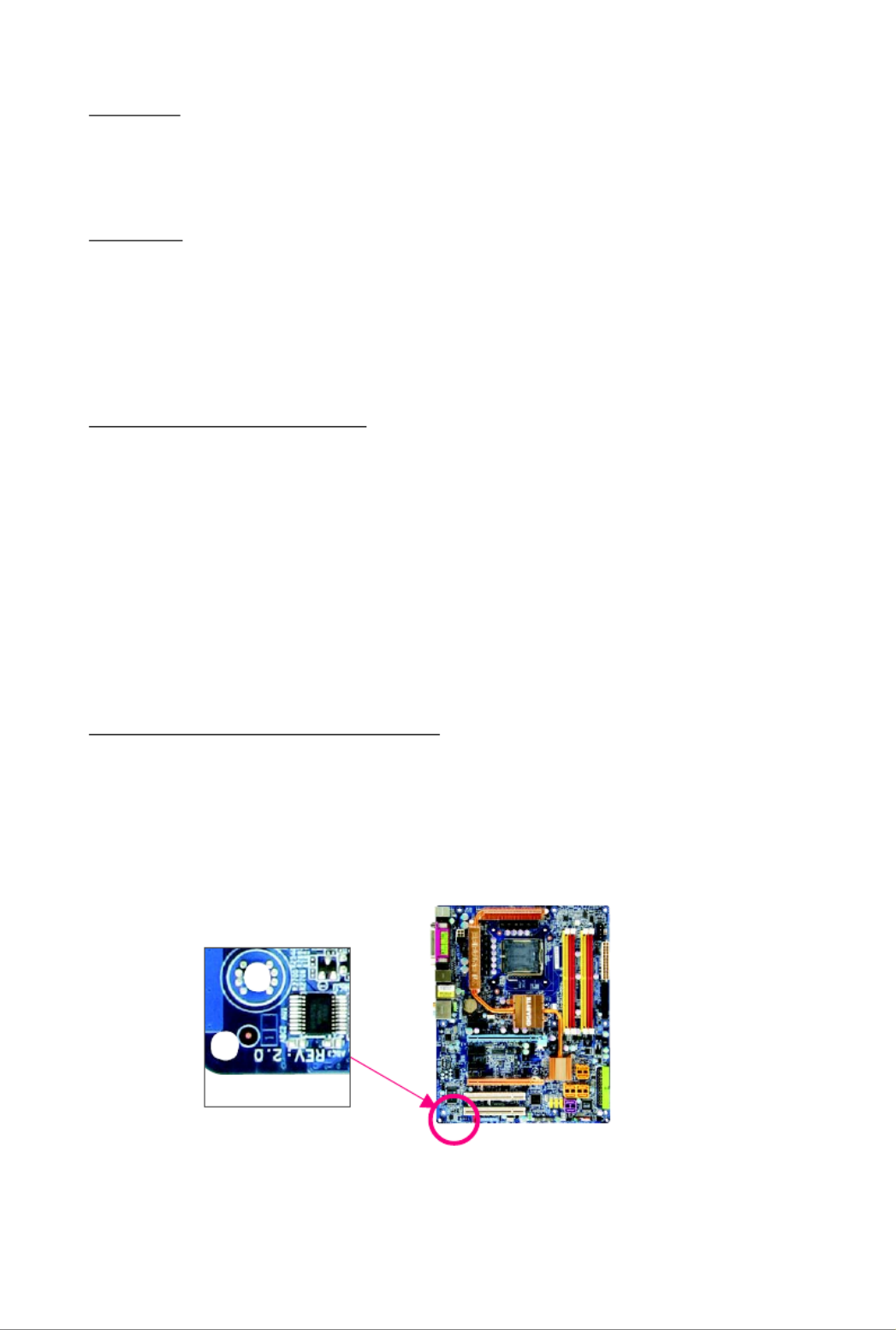
Identifying Your Motherboard Revision
The revision number on your motherboard looks like this: "REV: X.X." For example, "REV: 1.0"
means the revision of the motherboard is 1.0. Check your motherboard revision before updating
motherboard BIOS, drivers, or when looking for technical information.
Example:

- 5 -
Table of Contents
Box Contents ................................................................................................................. 7
Optional Items................................................................................................................. 7
GA-G31M-S2L/GA-G31M-S2C Motherboard Layout ..................................................... 8
Block Diagram................................................................................................................ 9
Chapter 1 Hardware Installation ...................................................................................11
1-1 Installation Precautions .................................................................................... 11
1-2 Product Specifications .................................................................................... 12
1-3 Installing the CPU and CPU Cooler .............................................................. 15
1-3-1 Installing the CPU ................................................................................................ 15
1-3-2 Installing the CPU Cooler ................................................................................... 17
1-4 Installing the Memory ..................................................................................... 18
1-4-1 Dual Channel Memory Configuration ................................................................ 18
1-4-2 Installing a Memory ............................................................................................. 19
1-5 Installing an Expansion Card ......................................................................... 20
1-6 Back Panel Connectors ................................................................................. 21
1-7 Internal Connectors ........................................................................................ 23
Chapter 2 BIOS Setup................................................................................................. 33
2-1 Startup Screen ................................................................................................ 34
2-2 The Main Menu .............................................................................................. 35
2-3 Standard CMOS Features ............................................................................. 37
2-4 Advanced BIOS Features .............................................................................. 39
2-5 Integrated Peripherals ..................................................................................... 42
2-6 Power Management Setup ............................................................................. 45
2-7 PnP/PCI Configurations ................................................................................. 47
2-8 PC Health Status ........................................................................................... 48
2-9 MB Intelligent Tweaker(M.I.T.) ....................................................................... 49
2-10 Load Fail-Safe Defaults ................................................................................... 52
2-11 Load Optimized Defaults ................................................................................. 52
2-12 Set Supervisor/User Password ..................................................................... 53
2-13 Save & Exit Setup ......................................................................................... 54
2-14 Exit Without Saving ....................................................................................... 54

- 7 -
Box Contents
GA-G31M-S2L or GA-G31M-S2C motherboard
Motherboard driver disk
User's Manual
One IDE cable and one floppy disk drive cable
Two SATA 3Gb/s cables
I/O Shield
Optional Items
2-port USB 2.0 bracket (Part No. 12CR1-1UB030-51R)
2-port SATA power cable (Part No. 12CF1-2SERPW-01R)
S/PDIF out cable (Part No. 12CR1-1SPOUT-02R)
•The box contents above are for reference only and the actual items shall depend on product package you obtain.
The box contents are subject to change without notice.
•The motherboard image is for reference only.

- 8 -
GA-G31M-S2L/GA-G31M-S2C Motherboard Layout
KB_MS CPU_FAN
LGA775
ATX
GA-G31M-S2L/GA-G31M-S2C
F_AUDIO
SYS_FAN
PCIE_16
IDE
BAT
IT8718
ATX_12V
Intel® G31
USB
LAN
AUDIO
LPT
R_USB
COMA
CLR_CMOS
FDD
DDRII1
DDRII2
VGA
Intel® ICH7
SATAII0
F_PANEL
PWR_LED
SATAII1
CI
CD_IN
F_USB1
CODEC
SPDIF_O
MBIOS
PCI1
PCI2
F_USB2
PCIE_1
SATAII2
SATAII3
Only for GA-G31M-S2L.
Only for GA-G31M-S2C.
RTL8111C
RTL8102E
- 9 -
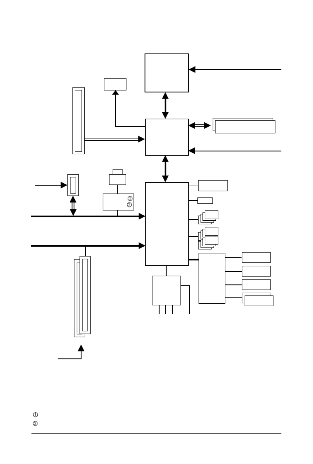
Block Diagram
LGA775
Processor
Host
Interface
Intel®
G31 GMCH CLK
(333/266/200 MHz)
Intel ®
ICH7
BIOS
2 PCI
PCI Bus
PCI Express Bus
Dual Channel Memory
4 SATA 3Gb/s
PCI CLK
(33 MHz)
PCIe CLK
(100 MHz)
PCI Express x16
8 USB Ports
IT8718
Floppy
PS/2 KB/Mouse
LPT Port
CPU CLK+/-
(333/266/200 MHz)
D-Sub
1 PCI Express x1
PCIe CLK
(100 MHz) x 1
Line-Out(Front Speaker Out)
MIC(Center/Subwoofer Speaker Out)
Line-In(Rear Speaker Out)
SPDIF Out
CODEC
ATA-100/66/33 IDE Channel
COM Port
DDR2 800/667 MHz
RJ45
LAN
RTL8111C
RTL8102E
Only for GA-G31M-S2L.
Only for GA-G31M-S2C.

- 10 -

Hardware Installation- 11 -
1-1 Installation Precautions
The motherboard contains numerous delicate electronic circuits and components which can become
damaged as a result of electrostatic discharge (ESD). Prior to installation, carefully read the user's
manual and follow these procedures:
•Prior to installation, do not remove or break motherboard S/N (Serial Number) sticker or
warranty sticker provided by your dealer. These stickers are required for warranty validation.
•Always remove the AC power by unplugging the power cord from the power outlet before
installing or removing the motherboard or other hardware components.
•When connecting hardware components to the internal connectors on the motherboard,
make sure they are connected tightly and securely.
•When handling the motherboard, avoid touching any metal leads or connectors.
•It is best to wear an electrostatic discharge (ESD) wrist strap when handling electronic
components such as a motherboard, CPU or memory. If you do not have an ESD wrist strap,
keep your hands dry and first touch a metal object to eliminate static electricity.
•Prior to installing the motherboard, please have it on top of an antistatic pad or within an
electrostatic shielding container.
•Before unplugging the power supply cable from the motherboard, make sure the power supply
has been turned off.
•Before turning on the power, make sure the power supply voltage has been set according to
the local voltage standard.
•Before using the product, please verify that all cables and power connectors of your hardware
components are connected.
•To prevent damage to the motherboard, do not allow screws to come in contact with the
motherboard circuit or its components.
•Make sure there are no leftover screws or metal components placed on the motherboard or
within the computer casing.
•Do not place the computer system on an uneven surface
.
•Do not place the computer system in a high-temperature environment.
•Turning on the computer power during the installation process can lead to damage to system
components as well as physical harm to the user.
•If you are uncertain about any installation steps or have a problem related to the use of the
product, please consult a certified computer technician.
Chapter 1 Hardware Installation

Hardware Installation- 13 -
Internal Connectors 1 x 24-pin ATX main power connector
1 x 4-pin ATX 12V power connector
1 x floppy disk drive connector
1 x IDE connector
4 x SATA 3Gb/s connectors
1 x CPU fan header
1 x system fan header
1 x front panel header
1 x front panel audio header
1 x CD In connector
1 x S/PDIF Out header
2 x USB 2.0/1.1 headers
1 x chassis intrusion header
1 x power LED header
Back Panel 1 x PS/2 keyboard port
Connectors 1 x PS/2 mouse port
1 x parallel port
1 x serial port
1 x D-Sub port
4 x USB 2.0/1.1 ports
1 x RJ-45 port
3 x audio jacks (Line In/Line Out/Microphone)
I/O Controller iTE IT8718 chip
Hardware Monitor System voltage detection
CPU temperature detection
CPU/System fan speed detection
CPU overheating warning
CPU/System fan fail warning
CPU fan speed control
BIOS 1 x 4 Mbit flash
Use of licensed AWARD BIOS
PnP 1.0a, DMI 2.0, SM BIOS 2.4, ACPI 1.0b

GA-G31M-S2L/S2C Motherboard - 14 -
(Note 1) Based on standard PC architecture, a certain amount of memory is reserved for system usage
and therefore the actual memory size is less than the stated amount. For example, 4 GB of
memory size will instead be shown as 3.xx GB during system startup.
(Note 2) Available functions in EasyTune may differ by motherboard model.
Unique Features Support for @BIOS
Support for Download Center
Support for Q-Flash
Support for EasyTune (Note 2)
Support for Xpress Install
Support for Xpress Recovery2
Support for Virtual DualBIOS
Bundled Software Norton Internet Security (OEM version)
Operating System Support for Microsoft® Windows® Vista/XP
Form Factor Micro ATX form factor; 24.4cm x 19.3cm

Hardware Installation- 15 -
1-3 Installing the CPU and CPU Cooler
Read the following guidelines before you begin to install the CPU:
•Make sure that the motherboard supports the CPU.
(Go to GIGABYTE's website for the latest CPU support list.)
•Always turn off the computer and unplug the power cord from the power outlet before
installing the CPU to prevent hardware damage.
•Locate the pin one of the CPU. The CPU cannot be inserted if oriented incorrectly. (Or you
may locate the notches on both sides of the CPU and alignment keys on the CPU socket.)
•Apply an even and thin layer of thermal grease on the surface of the CPU.
•Do not turn on the computer if the CPU cooler is not installed, otherwise overheating and
damage of the CPU may occur.
•Set the CPU host frequency in accordance with the CPU specifications. It is not recom-
mended that the system bus frequency be set beyond hardware specifications since it
does not meet the standard requirements for the peripherals. If you wish to set the fre-
quency beyond the standard specifications, please do so according to your hardware
specifications including the CPU, graphics card, memory, hard drive, etc.
1-3-1 Installing the CPU
A. Locate the alignment keys on the motherboard CPU socket and the notches on the CPU.
NotchNotch
Alignment KeyAlignment Key
LGA 775 CPU
LGA775 CPU Socket
Pin One Corner of the CPU Socket
Triangle Pin One Marking on the CPU

GA-G31M-S2L/S2C Motherboard - 16 -
B. Follow the steps below to correctly install the CPU into the motherboard CPU socket.
Step 2:
Lift the metal load plate from the CPU socket.
(DO NOT touch socket contacts.)
Step 4:
Hold the CPU with your thumb and index
fingers. Align the CPU pin one marking (triangle)
with the pin one corner of the CPU socket (or
you may align the CPU notches with the socket
alignment keys) and gently insert the CPU
into position.
Step 3:
Remove the protective socket cover from the
load plate. (To protect the CPU socket, always
replace the protective socket cover when the
CPU is not installed.)
Step 5:
Once the CPU is properly inserted, replace
the load plate and push the CPU socket lever
back into its locked position.
Before installing the CPU, make sure to turn off the computer and unplug the power
cord from the power outlet to prevent damage to the CPU.
Step 1:
Completely raise the CPU socket lever.
CPU Socket Lever

Hardware Installation- 17 -
1-3-2 Installing the CPU Cooler
Follow the steps below to correctly install the CPU cooler on the motherboard. (The following procedure
uses Intel® boxed cooler as the example cooler.)
Step 1:
Apply an even and thin layer of thermal grease
on the surface of the installed CPU.
Step 3:
Place the cooler atop the CPU, aligning the
four push pins through the pin holes on the
motherboard. Push down on the push pins
diagonally.
Step 4:
You should hear a "click" when pushing down each
push pin. Check that the Male and Female push pins
are joined closely. (Refer to your CPU cooler instal-
lation manual for instructions on installing the cooler.)
Use extreme care when removing the CPU cooler because the thermal grease/tape between
the CPU cooler and CPU may adhere to the CPU. Inadequately removing the CPU cooler may
damage the CPU.
Step 5:
After the installation, check the back of the
motherboard. If the push pin is inserted as the
picture above, the installation is complete.
Step 6:
Finally, attach the power connector of the CPU
cooler to the CPU fan header (CPU_FAN) on
the motherboard.
Male
Push Pin
Female
Push Pin
The Top
of Female
Push Pin
Direction of
the Arrow Sign
on the Male
Push Pin
Step 2:
Before installing the cooler, note the direction
of the arrow sign on the male push pin.
(Turning the push pin along the direction of
arrow is to remove the cooler, on the contrary,
is to install.)

GA-G31M-S2L/S2C Motherboard - 18 -
1-4 Installing the Memory
Read the following guidelines before you begin to install the memory:
•Make sure that the motherboard supports the memory. It is recommended that memory of
the same capacity, brand, speed, and chips be used.
(Go to GIGABYTE's website for the latest memory support list.)
•Always turn off the computer and unplug the power cord from the power outlet before
installing the memory to prevent hardware damage.
•Memory modules have a foolproof design. A memory module can be installed in only one
direction. If you are unable to insert the memory, switch the direction.
DDRII1
DDRII2
1-4-1 Dual Channel Memory Configuration
This motherboard provides two DDR2 memory sockets and supports Dual Channel
Technology. After the memory is installed, the BIOS will automatically detect the
specifications and capacity of the memory. Enabling Dual Channel memory mode
will double the original memory bandwidth.
The two DDR2 memory sockets are divided into two channels and each channel has one memory
socket as following:
Channel 0: DDRII1
Channel 1: DDRII2
Due to chipset limitation, read the following guidelines before installing the memory in Dual Channel mode.
1. Dual Channel mode cannot be enabled if only one DDR2 memory module is installed.
2. When enabling Dual Channel mode with two memory modules, it is recommended that
memory of the same capacity, brand, speed, and chips be used.

Hardware Installation- 19 -
1-4-2 Installing a Memory
Notch
DDR2 DIMM
Before installing a memory module , make sure to turn off the computer and unplug
the power cord from the power outlet to prevent damage to the memory module.
DDR2 DIMMs are not compatible to DDR DIMMs. Be sure to install DDR2 DIMMs on
this motherboard.
A DDR2 memory module has a notch, so it can only fit in one direction. Follow the steps below to
correctly install your memory modules in the memory sockets.
Step 1:
Note the orientation of the memory module. Spread the retaining
clips at both ends of the memory socket. Place the memory
module on the socket. As indicated in the picture on the left,
place your fingers on the top edge of the memory, push down
on the memory and insert it vertically into the memory socket.
Step 2:
The clips at both ends of the socket will snap into place when
the memory module is securely inserted.

GA-G31M-S2L/S2C Motherboard - 20 -
1-5 Installing an Expansion Card
Read the following guidelines before you begin to install an expansion card:
•Make sure the motherboard supports the expansion card. Carefully read the manual that
came with your expansion card.
•Always turn off the computer and unplug the power cord from the power outlet before
installing an expansion card to prevent hardware damage.
Follow the steps below to correctly install your expansion card in the expansion slot.
1. Locate an expansion slot that supports your card. Remove the metal slot cover from the chassis back panel.
2. Align the card with the slot, and press down on the card until it is fully seated in the slot.
3. Make sure the metal contacts on the card are completely inserted into the slot.
4. Secure the card's metal bracket to the chassis back panel with a screw.
5. After installing all expansion cards, replace the chassis cover(s).
6. Turn on your computer. If necessary, go to BIOS Setup to make any required BIOS changes for
your expansion card(s).
7. Install the driver provided with the expansion card in your operating system.
PCI Slot
PCI Express p20-x1 Slot
PCI Express x16 Slot
Example: Installing and Removing a PCI Express x16 Graphics Card:
•Installing a Graphics Card:
Gently push down on the top edge of the card
until it is fully inserted into the PCI Express x16
slot. Make sure the card is securely seated in
the slot and does not rock.
•Removing the Card:
Gently push back on the lever on the slot and then lift the card straight out
from the slot.

Hardware Installation- 21 -
1-6 Back Panel Connectors
PS/2 Keyboard and PS/2 Mouse Port
Use the upper port (green) to connect a PS/2 mouse and the lower port (purple) to connect a PS/2
keyboard.
Parallel Port
Use the parallel port to connect devices such as a printer, scanner and etc. The parallel port is also
called a printer port.
Serial Port
Use the serial port to connect devices such as a mouse, modem or other peripherals.
D-Sub Port
The D-Sub port supports a 15-pin D-Sub connector. Connect a monitor that supports D-Sub
connection to this port.
USB Port
The USB port supports the USB 2.0/1.1 specification. Use this port for USB devices such as an
USB keyboard/mouse, USB printer, USB flash drive and etc.
RJ-45 LAN Port
The Gigabit Ethernet LAN port provides Internet connection at up to 1 Gbps data rate. The following
describes the states of the LAN port LEDs.
•When removing the cable connected to a back panel connector, first remove the cable
from your device and then remove it from the motherboard.
•When removing the cable, pull it straight out from the connector. Do not rock it side to side
to prevent an electrical short inside the cable connector.
Activity LED
Connection/
Speed LED Activity LED:
State Description
Blinking Data transmission or receiving is occurring
Off No data transmission or receiving is occurring
Connection/Speed LED:
State Description
Orange 1 Gbps data rate
Green 100 Mbps data rate
Off 10 Mbps data rate
LAN Port
Only for GA-G31M-S2L.
GA-G31M-S2L/S2C Motherboard - 24 -
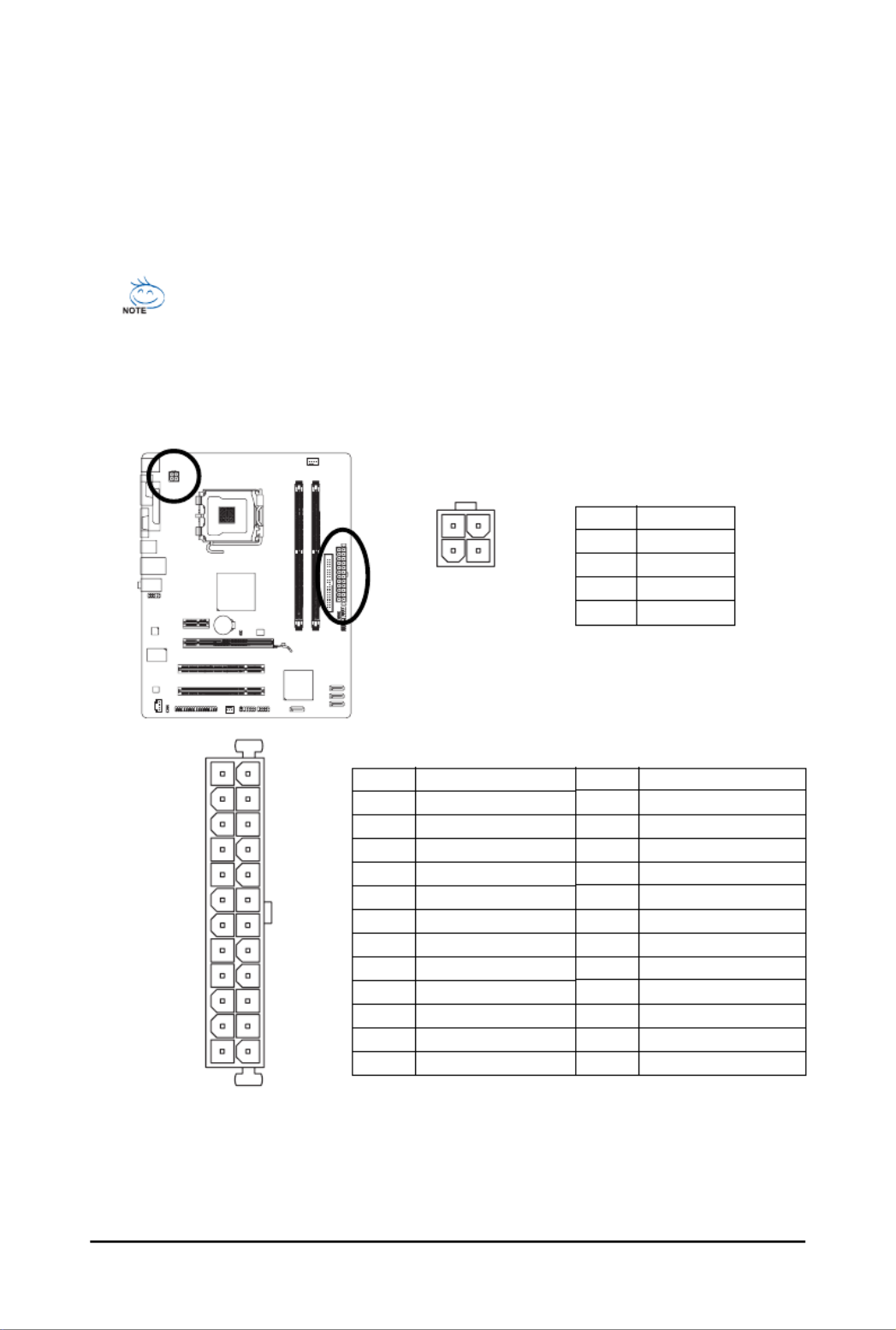
1/2) ATX_12V/ATX (2x2 12V Power Connector and 2x12 Main Power Connector)
With the use of the power connector, the power supply can supply enough stable power to all the
components on the motherboard. Before connecting the power connector, first make sure the
power supply is turned off and all devices are properly installed. The power connector possesses
a foolproof design. Connect the power supply cable to the power connector in the correct orientation.
The 12V power connector mainly supplies power to the CPU. If the 12V power connector is not
connected, the computer will not start.
•To meet expansion requirements, it is recommended that a power supply that can withstand
high power consumption be used (400W or greater). If a power supply is used that does not
provide the required power, the result can lead to an unstable or unbootable system.
•The main power connector is compatible with power supplies with 2x10 power
connectors. When using a 2x12 power supply, remove the protective cover from the
main power connector on the motherboard. Do not insert the power supply cable into pins
under the protective cover when using a 2x10 power supply.
ATX_12V :
ATX :
Pin No. Definition
1 GND
2 GND
3 +12V
4 +12V
Pin No. Definition
13 3.3V
14 -12V
15 GND
16 PS_ON(soft On/Off)
17 GND
18 GND
19 GND
20 -5V
21 +5V
22 +5V
23 +5V (Only for 2x12-pin ATX)
24 GND (Only for 2x12-pin ATX)
Pin No. Definition
1 3.3V
2 3.3V
3 GND
4 +5V
5 GND
6 +5V
7 GND
8 Power Good
9 5V SB(stand by +5V)
10 +12V
11 +12V (Only for 2x12-pin ATX)
12 3.3V (Only for 2x12-pin ATX)
ATX_12V
4
2
3
1
131
24
12
ATX

GA-G31M-S2L/S2C Motherboard - 26 -
6) IDE (IDE Connector)
The IDE connector supports up to two IDE devices such as hard drives and optical drives. Before
attaching the IDE cable, locate the foolproof groove on the connector. If you wish to connect two IDE
devices, remember to set the jumpers and the cabling according to the role of the IDE devices (for
example, master or slave). (For information about configuring master/slave settings for the IDE
devices, read the instructions from the device manufacturers.)
7) SATAII0/1/2/3 (SATA 3Gb/s Connectors, Controlled by ICH7)
The SATA connectors conform to SATA 3Gb/s standard and are compatible with SATA 1.5Gb/s
standard. Each SATA connector supports a single SATA device.
Pin No. Definition
1 GND
2 TXP
3 TXN
4 GND
5 RXN
6 RXP
7 GND
12
3940
SATAII0
SATAII1
SATAII2
SATAII3
17
17
1
7
1
7
Please connect the L-shaped end
of the SATA 3Gb/s cable to your
SATA hard drive.

Hardware Installation- 27 -
8) PWR_LED (System Power LED Header)
This header can be used to connect a system power LED on the chassis to indicate system power
status. The LED is on when the system is operating. The LED keeps blinking when the system is
in S1 sleep state. The LED is off when the system is in S3/S4 sleep state or powered off (S5).
Pin No. Definition
1 MPD+
2 MPD-
3 MPD-
System Status LED
S0 On
S1 Blinking
S3/S4/S5 Off
9) BAT(BATTERY)
The battery provides power to keep the values (such as BIOS configurations, date, and time
information) in the CMOS when the computer is turned off. Replace the battery when the battery
voltage drops to a low level, or the CMOS values may not be accurate or may be lost.
•Always turn off your computer and unplug the power cord before replacing the battery.
•Replace the battery with an equivalent one. Danger of explosion if the battery is replaced
with an incorrect model.
•Contact the place of purchase or local dealer if you are not able to replace the battery by
yourself or uncertain about the battery model.
•When installing the battery, note the orientation of the positive side (+) and the negative
side (-) of the battery (the positive side should face up).
•Used batteries must be handled in accordance with local environmental regulations.
You may clear the CMOS values by removing the battery:
1. Turn off your computer and unplug the power cord.
2. Gently remove the battery from the battery holder and wait for one minute.
(Or use a metal object like a screwdriver to touch the positive and
negative terminals of the battery holder, making them short for 5 seconds.)
3. Replace the battery.
4. Plug in the power cord and restart your computer.
1

GA-G31M-S2L/S2C Motherboard - 28 -
10) F_PANEL (Front Panel Header)
Connect the power switch, reset switch, speaker and system status indicator on the chassis front
panel to this header according to the pin assignments below. Note the positive and negative pins
before connecting the cables.
The front panel design may differ by chassis. A front panel module mainly consists of
power switch, reset switch, power LED, hard drive activity LED, speaker and etc. When
connecting your chassis front panel module to this header, make sure the wire assign-
ments and the pin assignments are matched correctly.
•PW (Power Switch):
Connects to the power switch on the chassis front panel. You may configure the way to turn off
your system using the power switch (refer to Chapter 2, "BIOS Setup," "Power Management
Setup," for more information).
•SPEAK (Speaker):
Connects to the speaker on the chassis front panel. The system reports system startup status
by issuing a beep code. One single short beep will be heard if no problem is detected at system
startup. If a problem is detected, the BIOS may issue beeps in different patterns to indicate the
problem. Refer to Chapter 5, "Troubleshooting," for information about beep codes.
•HD (IDE Hard Drive Activity LED)
Connects to the hard drive activity LED on the chassis front panel. The LED is on when the hard
drive is reading or writing data.
•RES (Reset Switch):
Connects to the reset switch on the chassis front panel. Press the reset switch to restart the
computer if the computer freezes and fails to perform a normal restart.
•NC:
No connection
System Status LED
S0 On
S1 Blinking
S3/S4/S5 Off
•MSG (Message/Power/Sleep LED):
Connects to the power status indicator on the chassis front panel. The
LED is on when the system is operating. The LED keeps blinking when
the system is in S1 sleep state. The LED is off when the system is in
S3/S4 sleep state or powered off (S5).
12
1920
HD-
HD+
RES+
RES-
NC
SPEAK-
MSG-
MSG+
PW-
PW+
SPEAK+
Message LED/
Power/
Sleep LED
Power Switch
Speaker Connector
IDE Hard Disk
Active LED
Reset Switch

Hardware Installation- 29 -
11) F_AUDIO (Front Panel Audio Header)
The front panel audio header supports Intel High Definition audio (HD) and AC'97 audio. You may
connect your chassis front panel audio module to this header. Make sure the wire assignments of
the module connector match the pin assignments of the motherboard header. Incorrect connection
between the module connector and the motherboard header will make the device unable to work
or even damage it.
For AC'97 Front Panel Audio:
For HD Front Panel Audio:
•The front panel audio header supports HD audio by default. If your chassis provides an
AC'97 front panel audio module, refer to the instructions on how to activate AC'97 functioninality
via the audio software in Chapter 5, "Configuring 2/4/5.1-Channel Audio."
•Audio signals will be present on both of the front and back panel audio connections
simultaneously. If you want to mute the back panel audio (only supported when using an HD
front panel audio module), refer to Chapter 5, "Configuring 2/4/5.1-Channel Audio."
•Some chassis provide a front panel audio module that has separated connectors on each
wire instead of a single plug. For information about connecting the front panel audio
module that has different wire assignments, please contact the chassis manufacturer.
Pin No. Definition
1 MIC
2 GND
3 MIC Power
4 NC
5 Line Out (R)
6 NC
7 NC
8 No Pin
9 Line Out (L)
10 NC
12) CD_IN (CD In Connector)
You may connect the audio cable that came with your optical drive to the header.
Pin No. Definition
1 CD-L
2 GND
3 GND
4 CD-R
1
2
9
10
1
Pin No. Definition
1 MIC2_L
2 GND
3 MIC2_R
4 -ACZ_DET
5 LINE2_R
6 FAUDIO_JD
7 GND
8 No Pin
9 LINE2_L
10 FAUDIO_JD

Hardware Installation- 31 -
Open: Normal
Short: Clear CMOS Values
15) CLR_CMOS (Clearing CMOS Jumper)
Use this jumper to clear the CMOS values (e.g. date information and BIOS configurations) and
reset the CMOS values to factory defaults. To clear the CMOS values, place a jumper cap on the
two pins to temporarily short the two pins or use a metal object like a screwdriver to touch the two
pins for a few seconds.
•Always turn off your computer and unplug the power cord from the power outlet before
clearing the CMOS values.
•After clearing the CMOS values and before turning on your computer, be sure to remove
the jumper cap from the jumper. Failure to do so may cause damage to the motherboard.
•After system restart, go to BIOS Setup to load factory defaults (select Load Optimized
Defaults) or manually configure the BIOS settings (refer to Chapter 2, "BIOS Setup," for
BIOS configurations).
16) CI (Chassis Intrusion Header)
This motherboard provides a chassis detection feature that detects if the chassis cover has been
removed. This function requires a chassis with chassis intrusion detection design.
Pin No. Definition
1 Signal
2 GND
1

- 33 - BIOS Setup
Chapter 2 BIOS Setup
BIOS (Basic Input and Output System) records hardware parameters of the system in the CMOS on the
motherboard. Its major functions include conducting the Power-On Self-Test (POST) during system
startup, saving system parameters and loading operating system, etc. BIOS includes a BIOS Setup
program that allows the user to modify basic system configuration settings or to activate certain system
features. When the power is turned off, the battery on the motherboard supplies the necessary power
to the CMOS to keep the configuration values in the CMOS.
To access the BIOS Setup program, press the <Delete> key during the POST when the power is turned
on. To see more advanced BIOS Setup menu options, you can press <Ctrl> + <F1> in the main menu
of the BIOS Setup program.
To upgrade the BIOS, use either the GIGABYTE Q-Flash or @BIOS utility.
•Q-Flash allows the user to quickly and easily upgrade or back up BIOS without entering the
operating system.
•@BIOS is a Windows-based utility that searches and downloads the latest version of BIOS from the
Internet and updates the BIOS.
For instructions on using the Q-Flash and @BIOS utilities, refer to Chapter 4, "BIOS Update Utilities."
•Because BIOS flashing is potentially risky, if you do not encounter problems using the
current version of BIOS, it is recommended that you not flash the BIOS. To flash the BIOS,
do it with caution. Inadequate BIOS flashing may result in system malfunction.
•BIOS will emit a beep code during the POST. Refer to Chapter 5, "Troubleshooting," for the
beep codes description.
•It is recommended that you not alter the default settings (unless you need to) to prevent
system instability or other unexpected results. Inadequately altering the settings may result
in system's failure to boot. If this occurs, try to clear the CMOS values and reset the board
to default values. (Refer to the "Load Optimized Defaults" section in this chapter or introduc-
tions of the battery/clearing CMOS jumper in Chapter 1 for how to clear the CMOS values.)

GA-G31M-S2L/S2C Motherboard - 34 -
2-1 Startup Screen
The following screen may appear when the computer boots.
Motherboard Model
BIOS Version
Function Keys
Award Modular BIOS v6.00PG, An Energy Star Ally
Copyright (C) 1984-2008, Award Software, Inc.
Intel G31 BIOS for G31M-S2L D9a
.
.
.
.
<DEL>: BIOS Setup/Q-Flash <F9>: XpressRecovery2 <F12>: Boot Menu <End>: Qflash
08/2 1 /2007-G31- I CH7-6A 7 9OG0 VC-00
Function Keys:
<DEL> : BIOS Setup/Q-Flash
Press the <Delete> key to enter BIOS Setup or to access the Q-Flash utility in BIOS Setup.
<F9> : Xpress Recovery2
If you have ever entered Xpress Recovery2 to back up hard drive data using the motherboard
driver disk, the <F9> key can be used for subsequent access to XpressRecovery2 during the
POST. For more information, refer to Chapter 4, "Xpress Recovery2."
<F12> : Boot Menu
Boot Menu allows you to set the first boot device without entering BIOS Setup. In Boot Menu, use
the up arrow key < > or the down arrow key< > to select the first boot device, then press <Enter>
to accept. To exit Boot Menu, press <Esc>. The system will directly boot from the device
configured in Boot Menu.
Note: The setting in Boot Menu is effective for one time only. After system restart, the device boot
order will still be based on BIOS Setup settings. You can access Boot Menu again to change the first
boot device setting as needed.
<End> : Q-Flash
Press the <End> key to access the Q-Flash utility directly without having to enter BIOS Setup first.

- 35 - BIOS Setup
2-2 The Main Menu
Once you enter the BIOS Setup program, the Main Menu (as shown below) appears on the screen. Use
arrow keys to move among the items and press <Enter> to accept or enter a sub-menu.
(Sample BIOS Version: GA-G31M-S2L D9a)
Main Menu Help
The onscreen description of a highlighted setup option is displayed on the bottom line of the Main Menu.
Submenu Help
While in a submenu, press <F1> to display a help screen (General Help) of function keys available for
the menu. Press <Esc> to exit the help screen. Help for each item is in the Item Help block on the right
side of the submenu.
BIOS Setup Program Function Keys
< >< >< >< > Move the selection bar to select an item
<Enter> Execute command or enter the submenu
<Esc> Main Menu: Exit the BIOS Setup program
Submenus: Exit current submenu
<Page Up> Increase the numeric value or make changes
<Page Down> Decrease the numeric value or make changes
<F1> Show descriptions of the function keys
<F2> Move cursor to the Item Help block on the right (submenus only)
<F5> Restore the previous BIOS settings for the current submenus
<F6> Load the Fail-Safe BIOS default settings for the current submenus
<F7> Load the Optimized BIOS default settings for the current submenus
<F8> Access the Q-Flash utility
<F9> Display system information
<F10> Save all the changes and exit the BIOS Setup program
<F11> Save CMOS to BIOS
<F12> Load CMOS from BIOS
•If you do not find the settings you want in the Main Menu or a submenu, press <Ctrl>+<F1>
to access more advanced options.
•When the system is not stable as usual, select the Load Optimized Defaults item to set
your system to its defaults.
•The BIOS Setup menus described in this chapter are for reference only and may differ by
BIOS version.
CMOS Setup Utility-Copyright (C) 1984-2008 Award Software
`Standard CMOS Features
`Advanced BIOS Features
`Integrated Peripherals
`Power Management Setup
`PnP/PCI Configurations
`PC Health Status
`MB Intelligent Tweaker(M.I.T.)
Load Fail-Safe Defaults
Load Optimized Defaults
Set Supervisor Password
Set User Password
Save & Exit Setup
Exit Without Saving
ESC: Quit KLJI: Select Item F11: Save CMOS to BIOS
F8: Q-Flash F10: Save & Exit Setup F12: Load CMOS from BIOS
Time, Date, Hard Disk Type...

- 37 - BIOS Setup
2-3 Standard CMOS Features
Date
Sets the system date. The date format is week (read-only), month, date and year. Select the
desired field and use the up arrow or down arrow key to set the date.
Time
Sets the system time. For example, 1 p.m. is 13:0:0. Select the desired field and use the up arrow
or down arrow key to set the time.
IDE Channel 0 Master/Slave
IDE HDD Auto-Detection
Press <Enter> to autodetect the parameters of the IDE/SATA device on this channel.
IDE Channel 0 Master/Slave
Configure your IDE/SATA devices by using one of the three methods below:
• Auto Lets BIOS automatically detect IDE/SATA devices during the POST. (Default)
• None If no IDE/SATA devices are used, set this item to None so the system will
skip the detection of the device during the POST for faster system startup.
• Manual Allows you to manually enter the specifications of the hard drive when the
hard drive access mode is set to CHS.
Access Mode Sets the hard drive access mode. Options are: Auto (default), CHS, LBA, Large.
IDE Channel 2, 3 Master/Slave
IDE Auto-Detection
Press <Enter> to autodetect the parameters of the IDE/SATA device on this channel.
Extended IDE Drive
Configure your IDE/SATA devices by using one of the two methods below:
• Auto Lets BIOS automatically detect IDE/SATA devices during the POST. (Default)
• None If no IDE/SATA devices are used, set this item to None so the system will
skip the detection of the device during the POST for faster system startup.
Access Mode Sets the hard drive access mode. Options are: Auto (default), Large.
CMOS Setup Utility-Copyright (C) 1984-2008 Award Software
Standard CMOS Features
Date (mm:dd:yy) Wed, Aug 22 2007
Time (hh:mm:ss) 10:31:24
`IDE Channel 0 Master [None]
`IDE Channel 0 Slave [None]
`IDE Channel 2 Master [None]
`IDE Channel 2 Slave [None]
`IDE Channel 3 Master [None]
`IDE Channel 3 Slave [None]
Drive A [1.44M, 3.5"]
Floppy 3 Mode Support [Disabled]
Halt On [All, But Keyboard]
Base Memory 640K
Extended Memory 510M
Total Memory 512M
KLJI: Move Enter: Select +/-/PU/PD: Value F10: Save ESC: Exit F1: General Help
F5: Previous Values F6: Fail-Safe Defaults F7: Optimized Defaults
Item Help
Menu Level`
Product specificaties
| Merk: | Gigabyte |
| Categorie: | Moederbord |
| Model: | GA-G31M-S2L |
| Breedte: | 243 mm |
| Diepte: | 193 mm |
| Type stroombron: | ATX |
| Aantal USB 2.0-poorten: | 4 |
| VGA (D-Sub)poort(en): | 1 |
| Microfoon, line-in ingang: | Ja |
| Aantal Ethernet LAN (RJ-45)-poorten: | 1 |
| Hoofdtelefoonuitgangen: | 3 |
| Audio-uitgang: | S/PDIF |
| Processor socket: | LGA 775 (Socket T) |
| Processorfabrikant: | Intel |
| Maximum intern geheugen: | 4 GB |
| Compatibele besturingssystemen: | Microsoft Windows Vista/XP/2000 |
| Audio-uitgangskanalen: | 5.1 kanalen |
| Audiochip: | Realtek ALC662 |
| S/PDIF-uitgang: | Ja |
| PS/2 poort(en): | 2 |
| Seriële poort(en): | 1 |
| Uitbreidingsslots: | 1 x PCI Express x16\n1 x PCI Express x1\n2 x PCI |
| Speciale eigenschappen: | -@BIOS \n-Q-Flash \n-EasyTune \n-Xpress Install \n-Xpress Recovery2 \n-Virtual Dual BIOS |
| Parallelle poort(en): | 1 |
| Moederbord form factor: | micro ATX |
| Aantal geheugenslots: | 2 |
| Aansluiting voor CPU koeler: | Ja |
| ATX Power connector (24-pin): | Ja |
| Aansluiting voor ventilator van voeding: | Ja |
| Aantal SATA-aansluitingen: | 4 |
| USB 2.0 aansluitingen: | 2 |
| Aansluiting voor audiopaneel aan voorzijde: | Ja |
| Aansluiting voor diskettestation: | Ja |
| Chassis intrusion aansluiting: | Ja |
| S/PDIF uitgang: | Ja |
| CD/AUX audio-ingang: | Ja |
| Aantal Parallel ATA aansluitingen: | 1 |
Heb je hulp nodig?
Als je hulp nodig hebt met Gigabyte GA-G31M-S2L stel dan hieronder een vraag en andere gebruikers zullen je antwoorden
Handleiding Moederbord Gigabyte

10 Maart 2025
11 Februari 2025
11 Februari 2025
11 Februari 2025
11 Februari 2025
11 Februari 2025
11 Februari 2025
11 Februari 2025
11 Februari 2025
11 Februari 2025
Handleiding Moederbord
- Moederbord Asus
- Moederbord Asrock
- Moederbord EPoX
- Moederbord Evga
- Moederbord MSI
- Moederbord Sharkoon
- Moederbord NZXT
- Moederbord Intel
- Moederbord Supermicro
- Moederbord ECS
- Moederbord Foxconn
- Moederbord Advantech
- Moederbord Elitegroup
- Moederbord Biostar
Nieuwste handleidingen voor Moederbord

8 April 2025
8 April 2025
3 April 2025
3 April 2025
3 April 2025
3 April 2025
2 April 2025
2 April 2025

29 Maart 2025
27 Maart 2025