Gigabyte GA-E240N Handleiding
Gigabyte
Moederbord
GA-E240N
Lees hieronder de 📖 handleiding in het Nederlandse voor Gigabyte GA-E240N (40 pagina's) in de categorie Moederbord. Deze handleiding was nuttig voor 34 personen en werd door 2 gebruikers gemiddeld met 4.5 sterren beoordeeld
Pagina 1/40

GA-E240N
User's Manual
Rev. 1001
12ME-E240N-1001R
Motherboard
GA-E240N
Jul. 5, 2012
Jul. 5, 2012
Motherboard
GA-E240N

Copyright
© 2012 GIGA-BYTE TECHNOLOGY CO., LTD. All rights reserved.
The trademarks mentioned in this manual are legally registered to their respective owners.
Disclaimer
Information in this manual is protected by copyright laws and is the property of GIGABYTE.
Changes to the specications and features in this manual may be made by GIGABYTE without
prior notice. No part of this manual may be reproduced, copied, translated, transmitted, or
published in any form or by any means without GIGABYTE's prior written permission.
In order to assist in the use of this product, carefully read the User's Manual.
For product-related information, check on our website at: http://www.gigabyte.com
Identifying Your Motherboard Revision
The revision number on your motherboard looks like this: "REV: X.X." For example, "REV:
1.0" means the revision of the motherboard is 1.0. Check your motherboard revision before
updating motherboard BIOS, drivers, or when looking for technical information.
Example:

- 4 -
Table of Contents
GA-E240N Motherboard Layout 5 ......................................................................................
GA-E240N Motherboard Block Diagram 6 .........................................................................
Chapter 1 Hardware Installation 7 .....................................................................................
1-1 Installation Precautions 7 ....................................................................................
1-2 ProductSpecications ...................................................................................... 8
1-3 Installing the Memory 10 .....................................................................................
1-4 Installing an Expansion Card 10 .........................................................................
1-5 Back Panel Connectors .................................................................................. 11
1-6 Internal Connectors 13 ........................................................................................
Chapter 2 BIOS Setup 21 ..................................................................................................
2-1 Startup Screen 21 ...............................................................................................
2-2 The Main Menu 22 ..............................................................................................
2-3 MB Intelligent Tweaker(M.I.T.) ........................................................................ 23
2-4 Standard CMOS Features 26 ..............................................................................
2-5 Advanced BIOS Features 27 ..............................................................................
2-6 Integrated Peripherals 28 ....................................................................................
2-7 Power Management Setup 30 .............................................................................
2-8 PC Health Status 32 ............................................................................................
2-9 Load Fail-Safe Defaults 33 ..................................................................................
2-10 Load Optimized Defaults 33 ................................................................................
2-11 Set Supervisor/User Password 34 ......................................................................
2-12 Save & Exit Setup 34 ..........................................................................................
2-13 Exit Without Saving 35 ........................................................................................
Chapter 3 Drivers Installation 35 ........................................................................................
3-1 Installing Chipset Drivers 35 ...............................................................................
3-2 Regulatory Statements 36 ...................................................................................

- 5 -
GA-E240N Motherboard Layout
The box contents above are for reference only and the actual items shall depend on the product package you obtain.
The box contents are subject to change without notice.
Box Contents
5GA-E240N motherboard
5Motherboard driver disk 5Two SATA cables
5User's Manual 5I/O Shield
KB_MS
CPU_FAN
AMD E-240 APU
AMD A45 FCH
ATX
GA-E240N
F_AUDIO
AUDIO
B_BIOS
DDR3_0
DDR3_1
BAT
F_PANEL
ATX_12V
CODEC
CLR_CMOS
M_BIOS
VGA
USB_LAN
PCI
SPDIF_O
F_USB1
CI
F_USB2
PWR_LED
COM
Realtek
GbE LAN
0
1
2
3
SATA2
USB_HDMI
iTE
Super I/O
SYS_FAN
LPT
- 6 -
GA-E240N Motherboard Block Diagram
Fordetailedproductinformation/limitation(s),referto"1-2ProductSpecications."
UMI
AMD A45 FCH
CPU CLK+/- (100 MHz)
S/PDIF Out
AMD
E-240 APU DDR3 1333 (O.C.)/1066 MHz
Dual BIOS
LPC
Bus COM
8 USB 2.0/1.1
4 SATA 3Gb/s
PCI Express Bus
PCIe CLK
(100 MHz)
x1
LAN
RJ45
Realtek
GbE LAN
D-Sub
HDMI
PCI Bus
1 PCI
PCI CLK
(33 MHz)
iTE
Super
I/O
PS/2 KB/Mouse
LPT
Single Channel
Line Out (Front Speaker Out)
MIC (Center/Subwoofer Speaker Out)
Line In (Rear Speaker Out)
CODEC

- 7 -
Chapter 1 Hardware Installation
1-1 Installation Precautions
The motherboard contains numerous delicate electronic circuits and components which can become
damaged as a result of electrostatic discharge (ESD). Prior to installation, carefully read the user's
manual and follow these procedures:
•Prior to installation, make sure the chassis is suitable for the motherboard.
•Prior to installation, do not remove or break motherboard S/N (Serial Number) sticker or
warranty sticker provided by your dealer. These stickers are required for warranty validation.
•Always remove the AC power by unplugging the power cord from the power outlet before
installing or removing the motherboard or other hardware components.
•When connecting hardware components to the internal connectors on the motherboard, make
sure they are connected tightly and securely.
•When handling the motherboard, avoid touching any metal leads or connectors.
•It is best to wear an electrostatic discharge (ESD) wrist strap when handling electronic
components such as a motherboard, CPU or memory. If you do not have an ESD wrist strap,
keepyourhandsdryandrsttouchametalobjecttoeliminatestaticelectricity.
•Prior to installing the motherboard, please have it on top of an antistatic pad or within an
electrostatic shielding container.
•Before unplugging the power supply cable from the motherboard, make sure the power supply
has been turned off.
•Before turning on the power, make sure the power supply voltage has been set according to
the local voltage standard.
•Before using the product, please verify that all cables and power connectors of your hardware
components are connected.
•To prevent damage to the motherboard, do not allow screws to come in contact with the
motherboard circuit or its components.
•Make sure there are no leftover screws or metal components placed on the motherboard or
within the computer casing.
•Do not place the computer system on an uneven surface.
•Do not place the computer system in a high-temperature environment.
•Turning on the computer power during the installation process can lead to damage to system
components as well as physical harm to the user.
•If you are uncertain about any installation steps or have a problem related to the use of the
product,pleaseconsultacertiedcomputertechnician.

- 8 -
1-2 ProductSpecications
APU Built in with an AMD E-240 Single-Core processor
Built in with an AMD Radeon™ HD 6310 (DirectX 11) graphics core
Chipset AMD A45 FCH
Memory 2 x 1.5V DDR3 DIMM sockets supporting up to 16 GB of system memory
* Due to a Windows 32-bit operating system limitation, when more than 4 GB of physical
memory is installed, the actual memory size displayed will be less than the size of the
physical memory installed.
Single channel memory architecture
Support for DDR3 1333 (O.C.)/1066 MHz memory modules
(Go to GIGABYTE's website for the latest supported memory speeds and memory
modules.)
Onboard
Graphics
Integrated in the APU:
- 1 x D-Sub port
- 1 x HDMI port, supporting a maximum resolution of 1920x1200
Audio Realtek ALC887 codec
HighDenitionAudio
2/4/5.1/7.1-channel
* Tocongure7.1-channelaudio,youhavetouseanHDfrontpanelaudiomodule
and enable the multi-channel audio feature through the audio driver.
Support for S/PDIF Out
LAN Realtek GbE LAN chip (10/100/1000 Mbit)
Expansion Slots 1 x PCI slot
Storage Interface Chipset:
- 4 x SATA 3Gb/s connectors supporting up to 4 SATA 3Gb/s devices
USB Chipset:
- Up to 8 USB 2.0/1.1 ports (4 ports on the back panel, 4 ports available through
the internal USB headers)
Internal
Connectors
1 x 24-pin ATX main power connector
1 x 4-pin ATX 12V power connector
4 x SATA 3Gb/s connectors
1 x CPU fan header
1 x system fan header
1 x front panel header
1 x front panel audio header
1 x S/PDIF Out header
2 x USB 2.0/1.1 headers
1 x chassis intrusion header
1 x power LED header
1 x Clear CMOS jumper

- 10 -
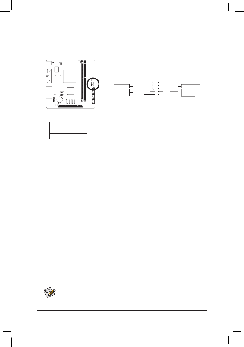
1-3 Installing the Memory
Read the following guidelines before you begin to install the memory:
•Make sure that the motherboard supports the memory. It is recommended that memory of the
same capacity, brand, speed, and chips be used.
(Go to GIGABYTE's website for the latest supported memory speeds and memory modules.)
•Always turn off the computer and unplug the power cord from the power outlet before installing the
memory to prevent hardware damage.
•Memory modules have a foolproof design. A memory module can be installed in only one direction.
If you are unable to insert the memory, switch the direction.
1-4 Installing an Expansion Card
Read the following guidelines before you begin to install an expansion card:
•Make sure the motherboard supports the expansion card. Carefully read the manual that came
with your expansion card.
•Always turn off the computer and unplug the power cord from the power outlet before installing an
expansion card to prevent hardware damage.
DDR3_0
DDR3_1
notch
DDR3 DIMM

- 11 -
1-5 Back Panel Connectors
PS/2 Keyboard and PS/2 Mouse Port
Use the upper port (green) to connect a PS/2 mouse and the lower port (purple) to connect a PS/2 keyboard.
Parallel Port
Use the parallel port to connect devices such as a printer, scanner and etc. The parallel port is also called
a printer port.
Serial Port
Use the serial port to connect devices such as a mouse, modem or other peripherals.
D-Sub Port
The D-Sub port supports a 15-pin D-Sub connector. Connect a monitor that supports D-Sub connection
to this port.
USB 2.0/1.1 Port
The USBport supportstheUSB2.0/1.1 specication.Use thisport for USB devicessuchas a USB
keyboard/mouse,USBprinter,USBashdriveandetc.
HDMI Port
The HDMI port is HDCP compliant and supports Dolby True HD and DTS HD
Master Audio formats. It also supports up to 192KHz/24bit 8-channel LPCM audio
output. You can use this port to connect your HDMI-supported monitor. The maximum supported resolution
is 1920x1200, but the actual resolutions supported are dependent on the monitor being used.
In Windows 7, select Start>Control Panel>Hardware and
Sound>Sound>Playback, set Intel(R) Display Audio to the
default playback device.
After installing the HDMI device, make sure to set the default sound playback device to HDMI.
(The item name may differ depending on your operating system. The screenshot below is from
Windows 7.)
- 12 -
Activity LED
Connection/
Speed LED
LAN Port
Activity LED:Connection/Speed LED:
State Description
Orange 1 Gbps data rate
Green 100 Mbps data rate
Off 10 Mbps data rate
State Description
Blinking Data transmission or receiving is occurring
Off No data transmission or receiving is occurring
RJ-45 LAN Port
The Gigabit Ethernet LAN port provides Internet connection at up to 1 Gbps data rate. The following
describes the states of the LAN port LEDs.
Line In Jack (Blue)
The default line in jack. Use this audio jack for line in devices such as an optical drive, walkman, etc.
Line Out Jack (Green)
The default line out jack. Use this audio jack for a headphone or 2-channel speaker. This jack can be used
toconnectfrontspeakersina4/5.1/7.1-channelaudioconguration.
Mic In Jack (Pink)
The default Mic in jack. Microphones must be connected to this jack.
•Whenremovingthecableconnectedtoabackpanelconnector,rstremovethecablefromyour
device and then remove it from the motherboard.
•When removing the cable, pull it straight out from the connector. Do not rock it side to side to prevent
an electrical short inside the cable connector.
Tocongure7.1-channelaudio,youhavetouseanHDfrontpanelaudiomoduleandenablethe
multi-channel audio feature through the audio driver.

- 13 -
1-6 Internal Connectors
Read the following guidelines before connecting external devices:
•First make sure your devices are compliant with the connectors you wish to connect.
•Before installing the devices, be sure to turn off the devices and your computer. Unplug the power
cord from the power outlet to prevent damage to the devices.
•After installing the device and before turning on the computer, make sure the device cable has
been securely attached to the connector on the motherboard.
112
4
3
5
11
10
9
2
6
1) ATX_12V
2) ATX
3) CPU_FAN
4) SYS_FAN
5) SATA2 0/1/2/3
6) PWR_LED
7) BAT
8) F_PANEL
9) F_AUDIO
10) SPDIF_O
11) F_USB1/F_USB2
12) CI
13) CLR_CMOS
8
13
7

- 15 -
3/4) CPU_FAN/SYS_FAN (Fan Headers)
The motherboard has a 3-pin CPU fan header (CPU_FAN) and a 4-pin system fan header (SYS_FAN).
Most fan headers possess a foolproof insertion design. When connecting a fan cable, be sure to connect
it in the correct orientation (the black connector wire is the ground wire). For optimum heat dissipation, it
is recommended that a system fan be installed inside the chassis.
•Be sure to connect fan cables to the fan headers to prevent your CPU and system from
overheating. Overheating may result in damage to the CPU or the system may hang.
•Thesefanheadersarenotcongurationjumperblocks.Donotplaceajumpercapontheheaders.
CPU_FAN
1
CPU_FAN:
Pin No. Denition
1 GND
2 +12V
3 Sense
5) SATA2 0/1/2/3 (SATA 3Gb/s Connectors)
The SATA connectors conform to SATA 3Gb/s standard and are compatible with SATA 1.5Gb/s standard.
Each SATA connector supports a single SATA device.
1
Pin No. Denition
1 GND
2 TXP
3 TXN
4 GND
5 RXN
6 RXP
7 GND
SYS_FAN
1
SYS_FAN:
Pin No. Denition
1 GND
2 +12V /Speed Control
3 Sense
4 VCC
7
7
77
1
1
1
SATA2 0123
- 16 -
6) PWR_LED (System Power LED Header)
This header can be used to connect a system power LED on the chassis to indicate system power status.
The LED is on when the system is operating. The LED is off when the system is in S3/S4 sleep state or
powered off (S5).
1
System Status LED
S0 On
S3/S4/S5 Off
Pin No. Denition
1 MPD+
2 MPD-
3 MPD-
7) BAT (Battery)
Thebatteryprovidespowertokeepthevalues(suchasBIOScongurations,date,andtimeinformation)
in the CMOS when the computer is turned off. Replace the battery when the battery voltage drops to a low
level, or the CMOS values may not be accurate or may be lost.
You may clear the CMOS values by removing the battery:
1. Turn off your computer and unplug the power cord.
2. Gently remove the battery from the battery holder and wait for one minute.
(Or use a metal object like a screwdriver to touch the positive and negative
terminals of the battery holder, making them short for 5 seconds.)
3. Replace the battery.
4. Plug in the power cord and restart your computer.
•Always turn off your computer and unplug the power cord before replacing the battery.
•Replace the battery with an equivalent one. Danger of explosion if the battery is replaced with
an incorrect model.
•Contact the place of purchase or local dealer if you are not able to replace the battery by yourself
or uncertain about the battery model.
•When installing the battery, note the orientation of the positive side (+) and the negative side (-)
of the battery (the positive side should face up).
•Used batteries must be handled in accordance with local environmental regulations.
- 17 -
The front panel design may differ by chassis. A front panel module mainly consists of power
switch, reset switch, power LED, hard drive activity LED and etc. When connecting your chassis
front panel module to this header, make sure the wire assignments and the pin assignments are
matched correctly.
8) F_PANEL (Front Panel Header)
Connect the power switch, reset switch and system status indicator on the chassis to this header according
to the pin assignments below. Note the positive and negative pins before connecting the cables.
•PW (Power Switch):
Connectstothepowerswitchonthechassisfrontpanel.Youmaycongurethewaytoturnoffyour
system using the power switch (refer to Chapter 2, "BIOS Setup," "Power Management Setup," for
more information).
•HD (Hard Drive Activity LED):
Connects to the hard drive activity LED on the chassis front panel. The LED is on when the hard drive
is reading or writing data.
•RES (Reset Switch):
Connects to the reset switch on the chassis front panel. Press the reset switch to restart the computer
if the computer freezes and fails to perform a normal restart.
•NC:
No connection.
•MSG (Message/Power/Sleep LED):
System Status LED
S0 On
S3/S4/S5 Off
Connects to the power status indicator on the chassis front panel. The LED
is on when the system is operating. The LED is off when the system is in S3/
S4 sleep state or powered off (S5).
12
910
NC
MSG-
PW-
MSG+
PW+
HD-
RES+
HD+
RES-
Message/Power/
Sleep LED
Power Switch
Hard Drive
Activity LED
Reset Switch

- 18 -
1
9) F_AUDIO (Front Panel Audio Header)
ThefrontpanelaudioheadersupportsIntelHighDenitionaudio(HD)andAC'97audio.Youmayconnect
your chassis front panel audio module to this header. Make sure the wire assignments of the module
connector match the pin assignments of the motherboard header. Incorrect connection between the module
connector and the motherboard header will make the device unable to work or even damage it.
For HD Front Panel Audio: For AC'97 Front Panel Audio:
•The front panel audio header supports HD audio by default.
•Audio signals will be present on both of the front and back panel audio connections simultaneously.
•Some chassis provide a front panel audio module that has separated connectors on each wire
instead of a single plug. For information about connecting the front panel audio module that has
different wire assignments, please contact the chassis manufacturer.
10) SPDIF_O (S/PDIF Out Header)
This header supports digital S/PDIF Out and connects a S/PDIF digital audio cable (provided by expansion
cards) for digital audio output from your motherboard to certain expansion cards like graphics cards and
sound cards. For example, some graphics cards may require you to use a S/PDIF digital audio cable for
digital audio output from your motherboard to your graphics card if you wish to connect an HDMI display
to the graphics card and have digital audio output from the HDMI display at the same time. For information
about connecting the S/PDIF digital audio cable, carefully read the manual for your expansion card.
Pin No. Denition
1 MIC2_L
2 GND
3 MIC2_R
4 -ACZ_DET
5 LINE2_R
6 GND
7 FAUDIO_JD
8 No Pin
9 LINE2_L
10 GND
Pin No. Denition
1 MIC
2 GND
3 MIC Power
4 NC
5 Line Out (R)
6 NC
7 NC
8 No Pin
9 Line Out (L)
10 NC
Pin No. Denition
1 SPDIFO
2 GND
9
1
10
2

- 19 -
11) F_USB1/F_USB2 (USB 2.0/1.1 Headers)
TheheadersconformtoUSB2.0/1.1specication.EachUSBheadercanprovidetwoUSBportsviaan
optional USB bracket. For purchasing the optional USB bracket, please contact the local dealer.
•Do not plug the IEEE 1394 bracket (2x5-pin) cable into the USB 2.0/1.1 header.
•Prior to installing the USB bracket, be sure to turn off your computer and unplug the power cord
from the power outlet to prevent damage to the USB bracket.
Pin No. Denition
1 Power (5V)
2 Power (5V)
3 USB DX-
4 USB DY-
5 USB DX+
6 USB DY+
7 GND
8 GND
9 No Pin
10 NC
2 10
1 9
12) CI (Chassis Intrusion Header)
This motherboard provides a chassis detection feature that detects if the chassis cover has been removed.
This function requires a chassis with chassis intrusion detection design.
1
Pin No. Denition
1 Signal
2 GND

- 20 -
13) CLR_CMOS (Clear CMOS Jumper)
UsethisjumpertocleartheCMOSvalues(e.g.dateinformationandBIOScongurations)andresetthe
CMOS values to factory defaults. To clear the CMOS values, use a metal object like a screwdriver to touch
the two pins for a few seconds.
•Always turn off your computer and unplug the power cord from the power outlet before clearing
the CMOS values.
•After system restart, go to BIOS Setup to load factory defaults (select Load Optimized Defaults) or
manuallyconguretheBIOSsettings(refertoChapter2,"BIOSSetup,"forBIOScongurations).
Open: Normal
Short: Clear CMOS Values
- 21 -
Chapter 2 BIOS Setup
2-1 Startup Screen
The following screens may appear when the computer boots.
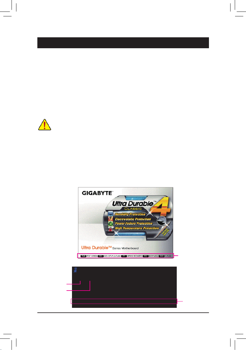
A. The LOGO Screen (Default)
B. The POST Screen
Function Keys
•BecauseBIOSashingispotentiallyrisky,if youdo notencounter problemsusing thecurrent
versionofBIOS,itisrecommended thatyou notashtheBIOS.ToashtheBIOS,doitwith
caution.InadequateBIOSashingmayresultinsystemmalfunction.
•It is recommended that you not alter the default settings (unless you need to) to prevent system
instability or other unexpected results. Inadequately altering the settings may result in system's
failure to boot. If this occurs, try to clear the CMOS values and reset the board to default values.
(Refer to the "Load Optimized Defaults" section in this chapter or introductions of the battery/clear
CMOS jumper in Chapter 1 for how to clear the CMOS values.)
BIOS (Basic Input and Output System) records hardware parameters of the system in the CMOS on the
motherboard. Its major functions include conducting the Power-On Self-Test (POST) during system startup,
saving system parameters and loading operating system, etc. BIOS includes a BIOS Setup program that allows
theusertomodifybasicsystemcongurationsettingsortoactivatecertainsystemfeatures.
When the power is turned off, the battery on the motherboard supplies the necessary power to the CMOS to
keepthecongurationvaluesintheCMOS.
To access the BIOS Setup program, press the <Delete> key during the POST when the power is turned on.
To upgrade the BIOS, use either the GIGABYTE Q-Flash or @BIOS utility.
•Q-Flash allows the user to quickly and easily upgrade or back up BIOS without entering the operating system.
•@BIOS is a Windows-based utility that searches and downloads the latest version of BIOS from the Internet
and updates the BIOS.
Motherboard Model
BIOS Version
Award Modular BIOS v6.00PG, An Energy Star Ally
Copyright (C) 1984-2012, Award Software, Inc.
GA-E240N E1a
.
.
.
.
<DEL>:BIOSSetup<F9>:XpressRecovery2<F12>:BootMenu<End>:Qash
06/29/2012-Zacate-Hudson-7A66EG05C-00
Function Keys

- 22 -
•IfyoudonotndthesettingsyouwantintheMainMenuorasubmenu,press<Ctrl>+<F1>to
access more advanced options.
•When the system is not stable as usual, select the item to set your Load Optimized Defaults
system to its defaults.
•The BIOS Setup menus described in this chapter are for reference only and may differ by BIOS
version.
The Functions of the <F11> and <F12> keys (For the Main Menu Only)
`F11: Save CMOS to BIOS
Thisfunctionallows youtosavethecurrentBIOSsettingstoaprole.Youcancreateupto8proles
(Prole1-8)andnameeachprole.Firstentertheprolename(toerasethedefaultprolename,usethe
SPACE key) and then press <Enter> to complete.
`F12: Load CMOS from BIOS
If your system becomes unstable and you have loaded the BIOS default settings, you can use this function
toload theBIOS settingsfromaprolecreated before,withoutthe hasslesofreconguringthe BIOS
settings.Firstselecttheproleyouwishtoloadandthenpress<Enter>tocomplete.
2-2 The Main Menu
Once you enter the BIOS Setup program, the Main Menu (as shown below) appears on the screen. Use arrow
keys to move among the items and press <Enter> to accept or enter a sub-menu.
(Sample BIOS Version: E1a)
CMOS Setup Utility-Copyright (C) 1984-2012 Award Software
Change CPU's Clock & Voltage
`MB Intelligent Tweaker(M.I.T.)
`Standard CMOS Features
`Advanced BIOS Features
`Integrated Peripherals
`Power Management Setup
`PC Health Status
Load Fail-Safe Defaults
Load Optimized Defaults
Set Supervisor Password
Set User Password
Save & Exit Setup
Exit Without Saving
ESC: Quit : Select Item F11: Save CMOS to BIOS
F8: Q-Flash F10: Save & Exit Setup F12: Load CMOS from BIOS

- 23 -
2-3 MB Intelligent Tweaker(M.I.T.)
Whether the system will work stably with the overclock/overvoltage settings you made is dependent
onyouroverallsystemcongurations.Incorrectlydoingoverclock/overvoltagemayresultindamage
to CPU, chipset, or memory and reduce the useful life of these components. This page is for advanced
users only and we recommend you not to alter the default settings to prevent system instability or
other unexpected results. (Inadequately altering the settings may result in system's failure to boot. If
this occurs, clear the CMOS values and reset the board to default values.)
CMOS Setup Utility-Copyright (C) 1984-2012 Award Software
MB Intelligent Tweaker(M.I.T.)
`IGX Conguration [Press Enter]
CPU Frequency(MHz) [Normal]
CPU Host Clock Control [Auto]
x CPU Host Clock 100
Set Memory Clock [Auto]
x Memory Clock x5.33 1066Mhz
`DRAM Conguration [Press Enter]
******** System Voltage Optimized
********
System Voltage Control [Auto]
x DIMM OverVoltage Control Auto
Normal CPU Vcore 1.3000V
: Move Enter: Select +/-/PU/PD: Value F10: Save ESC: Exit F1: General Help
F5: Previous Values F6: Fail-Safe Defaults F7: Optimized Defaults
Item Help
Menu Level `
(Note) This item is present only when you install a CPU that supports this feature.
CMOS Setup Utility-Copyright (C) 1984-2012 Award Software
IGX Conguration
: Move Enter: Select +/-/PU/PD: Value F10: Save ESC: Exit F1: General Help
F5: Previous Values F6: Fail-Safe Defaults F7: Optimized Defaults
Item Help
Menu Level ``
UMA Frame Buffer Size [Auto]
VGA Core Clock control [Auto]
x VGA Core Clock(MHz) 500
&IGXConguration
&UMA Frame Buffer Size
Frame buffer size is the total amount of system memory allocated solely for the onboard graphics controller.
MS-DOS, for example, will use only this memory for display. Options are: Auto (default), 256MB, 512MB,
1024MB.
&VGA Core Clock control
Allows you to determine whether to manually set the VGA Core clock. (Default: Auto)
&VGA Core Clock(MHz)
Allows you to set the onboard graphics clock. The adjustable range is from 300 MHz to 2000 MHz. This
itemiscongurableonlyiftheVGA Core Clock control Manual option is set to .

- 25 -
&Row Precharge Time
Options are: Auto (default), 5T~14T.
&Minimum RAS Active Time
Options are: Auto (default), 15T~36T.
&TwTr Command Delay
Options are: Auto (default), 4T~8T.
&Trfc0 for DIMM1
Options are: Auto (default), 90ns, 110ns, 160ns, 300ns, 350ns.
&Trfc1 for DIMM2
Options are: Auto (default), 90ns, 110ns, 160ns, 300ns, 350ns.
&Write Recovery Time
Options are: Auto (default), 5T~8T, 10T, 12T, 14T, 16T.
&Precharge Time
Options are: Auto (default), 4T~8T.
&Row Cycle Time
Options are: Auto (default), 20T~54T.
&RAS to RAS Delay
Options are: Auto (default), 4T~8T.
&Four Bank Activate Window
Options are: Auto (default), 16T~40T.
&Rank Interleaving
Enables or disables memory rank interleaving. Enabled allows the system to simultaneously access different
ranks of the memory to increase memory performance and stability. (Default: Enabled)
******** System Voltage Optimized ********
&System Voltage Control
Determines whether to manually set the system voltages. allows all voltage control items below Manual
tobecongurable.AutoletstheBIOSautomaticallysetthesystemvoltagesasrequired.(Default)
&DIMM Voltage
Allows you to set memory voltage.
Normal Supplies the memory voltage as required. (Default)
+0.100V ~ +0.300V The adjustable range is from +0.100V to +0.300V.
Note: Increasing memory voltage may result in damage to the memory or reduce the useful life of the
memory.
&Normal CPU Vcore
Displays the normal operating voltage of your CPU.
Product specificaties
| Merk: | Gigabyte |
| Categorie: | Moederbord |
| Model: | GA-E240N |
| Breedte: | 170 mm |
| Diepte: | 170 mm |
| Processormodel: | E-240 |
| Grafische adapter: | Radeon HD 6310 |
| Ethernet LAN: | Ja |
| Type stroombron: | ATX |
| Aantal USB 2.0-poorten: | 4 |
| VGA (D-Sub)poort(en): | 1 |
| Aantal HDMI-poorten: | 1 |
| Microfoon, line-in ingang: | Ja |
| Aantal Ethernet LAN (RJ-45)-poorten: | 1 |
| Hoofdtelefoonuitgangen: | 1 |
| Processor socket: | BGA 413 (Socket FT1) |
| Processorfabrikant: | AMD |
| Ingebouwde grafische adapter: | Ja |
| Audio-uitgangskanalen: | 7.1 kanalen |
| Ethernet interface type: | Fast Ethernet, Gigabit Ethernet |
| Chipset moederbord: | AMD A45 FCH |
| Geheugen slots type: | DIMM |
| Geheugen kanaal: | Eenkanaals |
| Ondersteunde opslagstationinterfaces: | SATA |
| PS/2 poort(en): | 2 |
| Seriële poort(en): | 1 |
| Component voor: | Nettop |
| Geheugen voltage: | 1.5 V |
| PCI-slots: | 1 |
| Compatibele processors: | AMD E |
| Parallelle poort(en): | 1 |
| Ondersteunde geheugen types: | DDR3-SDRAM |
| Moederbord chipset familie: | AMD |
| Moederbord form factor: | mini ITX |
| Aantal geheugenslots: | 2 |
| Supported memory clock speeds: | 1066,1333 MHz |
| BIOS type: | AWARD |
| Ondersteuning voor parallel processing: | Niet ondersteund |
| Aansluiting voor CPU koeler: | Ja |
| ATX Power connector (24-pin): | Ja |
| USB 2.0 aansluitingen: | 2 |
| Aansluiting voor audiopaneel aan voorzijde: | Ja |
| Aantal SATA II connectors: | 4 |
| Peripheral (Molex) power connectors (4-pin): | 1 |
Heb je hulp nodig?
Als je hulp nodig hebt met Gigabyte GA-E240N stel dan hieronder een vraag en andere gebruikers zullen je antwoorden
Handleiding Moederbord Gigabyte

10 Maart 2025
11 Februari 2025
11 Februari 2025
11 Februari 2025
11 Februari 2025
11 Februari 2025
11 Februari 2025
11 Februari 2025
11 Februari 2025
11 Februari 2025
Handleiding Moederbord
- Moederbord Asus
- Moederbord Asrock
- Moederbord EPoX
- Moederbord Evga
- Moederbord MSI
- Moederbord Sharkoon
- Moederbord NZXT
- Moederbord Intel
- Moederbord Supermicro
- Moederbord ECS
- Moederbord Foxconn
- Moederbord Advantech
- Moederbord Elitegroup
- Moederbord Biostar
Nieuwste handleidingen voor Moederbord

8 April 2025
8 April 2025
3 April 2025
3 April 2025
3 April 2025
3 April 2025
2 April 2025
2 April 2025

29 Maart 2025
27 Maart 2025