Gigabyte GA-8ST800 Handleiding
Gigabyte
Moederbord
GA-8ST800
Lees hieronder de 📖 handleiding in het Nederlandse voor Gigabyte GA-8ST800 (92 pagina's) in de categorie Moederbord. Deze handleiding was nuttig voor 21 personen en werd door 2 gebruikers gemiddeld met 4.5 sterren beoordeeld
Pagina 1/92

The author assumes no responsibility for
any errors or omissions that may appear in
this document nor does the author make a
commitment to update the information
contained herein.
Third-party brands and names are the
property of their respective owners.
Please do not remove any labels on
motherboard, this may void the warranty of
this motherboard.
Due to rapid change in technology, some of
the specifications might be out of date be-
fore publication of this booklet.


Declaration of Conformity
We, Manufacturer/Importer
(full address)
G.B.T. Technology Träding GMbH
Ausschlager Weg 41, 1F, 20537 Hamburg, Germany
declare that the product
( description of the apparatus, system, installation to which it refers)
Mother Board
GA-8ST800
is in conformity with
(reference to the specification under which conformity is declared)
in accordance with 89/336 EEC-EMC Directive
o EN 55011 Limits and methods of measurement
of radio disturbance characteristics of
industrial,scientific and medical (ISM
high frequency equipment
o EN 61000-3-2*
!!!!
! EN 60555-2
Disturbances in supply systems cause
by household appliances and similar
electrical equipment “Harmonics”
o EN 55013 Limits and methods of measurement
of radio disturbance characteristics of
broadcast receivers and associated
equipment
o EN 61000-3-3* Disturbances in supply systems cause
by household appliances and similar
electrical equipment “Voltage fluctuations”
o EN 55014 Limits and methods of measurement
of radio disturbance characteristics of
household electrical appliances,
portable tools and similar electrical
apparatus
!!!!
! EN 50081-1 Generic emission standard Part 1:
Residual commercial and light industry
!!!!
! EN 50082-1 Generic immunity standard Part 1:
Residual commercial and light industry
o EN 55015 Limits and methods of measurement
of radio disturbance characteristics of
fluorescent lamps and luminaries
Generic emission standard Part 2:
Industrial environment
o EN 55081-2
Immunity from radio interference of
broadcast receivers and associated
equipment
Generic emission standard Part 2:
Industrial environment
o EN 55082-2
!!
!!
! EN 55022 Limits and methods of measurement
of radio disturbance characteristics of
information technology equipment
lmmunity requirements for household
appliances tools and similar apparatus
o ENV 55104
Cabled distribution systems; Equipment
for receiving and/or distribution from
sound and television signals
EMC requirements for uninterruptible
power systems (UPS)
o EN50091-2
o EN 55020
o DIN VDE 0855
o part 10
o part 12
(EC conformity marking)
!!!!
! CE marking
The manufacturer also declares the conformity of above mentioned product
with the actual required safety standards in accordance with LVD 73/23 EEC
Safety requirements for mains operated
electronic and related apparatus for
household and similar general use
o EN 60950
o EN 60065
Safety of household and similar
electrical appliances
o EN 60335
Manufacturer/Importer
Signature:
Name:
(Stamp) Date : Aug. 28, 2002
!!
!!
! EN 60555-3
Timmy Huang
Timmy Huang
o EN 50091-1
Safety for information technology equipment
including electrical bussiness equipment
General and Safety requirements for
uninterruptible power systems (UPS)

FCC Part 15, Subpart B, Section 15.107(a) and Section 15.109(a),
Class B Digital Device
DECLARATION OF CONFORMITY
Per FCC Part 2 Section 2.1077(a)
Responsible Party Name:
Address:
Phone/Fax No:
hereby declares that the product
Product Name: Motherboard
Conforms to the following specifications:
This device complies with part 15 of the FCC Rules. Operation is
subject to the following two conditions: (1) This device may not
cause harmful and (2) this device must accept any inference received,
including that may cause undesired operation.
Representative Person’s Name:
Signature: Eric Lu
Supplementary Information:
Model Number: GA-8ST800
17358 Railroad Street
City of Industry, CA 91748
G.B.T. INC. (U.S.A.)
(818) 854-9338/ (818) 854-9339
Date:
ERIC LU
Aug. 28, 2002

USER'S MANUAL
GA-8ST800 Series
P4 Titan-DDR Motherboard
Pentium
®
4 Processor Motherboard
Rev. 1001
12ME-8ST800-1001

- 2 -GA-8ST800 Series Motherboard
English
Table of Content
Item Checklist .........................................................................................4
WARNING! ............................................................................................... 4
Chapter 1 Introduction ............................................................................ 5
Features Summary...................................................................................... 5
GA-8ST800 Motherboard Layout ............................................................... 7
GA-8ST800-L Motherboard Layout ............................................................ 8
Chapter 2 Hardware Installation Process ............................................... 9
Step 1: Install the Central Processing Unit (CPU) .................................... 10
Step 1-1: CPU Installation ............................................................................................ 10
Step 1-2: CPU Heat Sink Installation ........................................................................... 11
Step 2: Install memory modules................................................................ 12
Step 3: Install expansion cards ................................................................. 13
Step 4: Connect ribbon cables, cabinet wires and power supply ........... 14
Step 4-1: I/O Back Panel Introduction .........................................................................14
Step 4-2: Connectors Introduction ............................................................................... 16
Chapter 3 BIOS Setup ......................................................................... 23
The Main Menu (For example: BIOS Ver. : F1) ....................................... 24
Standard CMOS Features ........................................................................ 26
Advanced BIOS Features .......................................................................... 29
Integrated Peripherals .............................................................................. 31
Power Management Setup ....................................................................... 35

Table of Content
English
- 3 -
PnP/PCI Configurations ............................................................................ 38
PC Health Status ....................................................................................... 39
Frequency/Voltage Control ........................................................................ 41
Top Performance ...................................................................................... 43
Load Fail-Safe Defaults ............................................................................ 44
Load Optimized Defaults ........................................................................... 45
Set Supervisor/User Password .................................................................. 46
Save & Exit Setup ...................................................................................... 47
Exit Without Saving ................................................................................... 48
Chapter 4 Technical Reference ........................................................... 51
Block Diagram........................................................................................... 51
@BIOS
™ Introduction ................................................................................ 52
EasyTune
™
4 Introduction ......................................................................... 53
Flash BIOS Method Introduction .............................................................. 54
2- / 4- / 6-Channel Audio Function Introuction .......................................... 69
Chapter 5 Appendix .............................................................................. 77

- 4 -GA-8ST800 Series Motherboard
English
The GA-8ST800 Series motherboard
IDE cable x 1 / Floppy cable x 1
CD for motherboard driver & utility
GA-8ST800 Series user's manual
I/O Shield*
Quick PC Installation Guide
RAID Manual
Item Checklist
2 Port USB Cable x 1
4 Port USB Cable x 1
SPDIF KIT x 1 (SPD-KIT)
IEEE 1394 Cable x 1
Audio Combo Kit x 1
Motherboard Settings Label
* Only for GA-8ST800-L.
Computer motherboards and expansion cards contain very delicate Integrated Circuit (IC) chips. To
protect them against damage from static electricity, you should follow some precautions whenever you
work on your computer.
1. Unplug your computer when working on the inside.
2. Use a grounded wrist strap before handling computer components. If you do not have one,
touch both of your hands to a safely grounded object or to a metal object, such as the power
supply case.
3. Hold components by the edges and try not touch the IC chips, leads or connectors, or other
components.
4. Place components on a grounded antistatic pad or on the bag that came with the components
whenever the components are separated from the system.
5. Ensure that the ATX power supply is switched off before you plug in or remove the ATX power
connector on the motherboard.
If the motherboard has mounting holes, but they don’t line up with the holes on the base and there
are no slots to attach the spacers, do not become alarmed you can still attach the spacers to the
mounting holes. Just cut the bottom portion of the spacers (the spacer may be a little hard to cut off, so
be careful of your hands). In this way you can still attach the motherboard to the base without worrying
about short circuits. Sometimes you may need to use the plastic springs to isolate the screw from the
motherboard PCB surface, because the circuit wire may be near by the hole. Be careful, don’t let the
screw contact any printed circuit write or parts on the PCB that are near the fixing hole, otherwise it
may damage the board or cause board malfunctioning.
Installing the motherboard to the chassis…
WARNING!

Introduction
English
- 5 -
Chapter 1 Introduction
to be continued......
Features Summary
Form Factor — 29.5cm x 20.9cm ATX size form factor, 4 layers PCB
Motherboard — GA-8ST800 Series Motherboard:
GA-8ST800 or GA-8ST800-L
CPU — Socket 478 for Intel
®
Micro FC-PGA2 Pentium
® 4 processor
— Support Intel
® Pentium
®
4 (Northwood, 0.13 m) processor
— Support Intel
® Pentium
®
4 Processor with HT Technology
— Intel
® Pentium
® 4 400/533MHz FSB
— 2nd cache depends on CPU
Chipset — SiS 645DX Host/Memory controller
— SiS 962L MuTIOL Media I/O
Memory — 3 184-pin DDR DIMM sockets
— Supports DDR333/DDR266/DDR200 DIMM
— Supports Up to 2 un-buffer DIMM DDR333 or up to 3 un-buffer
Double-sided DIMM DDR266/200
— Supports up to 3GB DRAM (Max)(DDR266/200)
— Supports only 2.5V DDR DIMM
I/O Control — IT8705F
Slots — 1 Universal AGP slot (1X/2X/4X) device support
— 5 PCI slot supports 33MHz & PCI 2.2 compliant
On-Board IDE — 2 IDE bus master (UDMA33/ATA66/ATA100/ATA133) IDE ports
for up to 4 ATAPI devices
— Supports PIO mode3, 4 (UDMA 33/ATA66/ATA100/ATA133) IDE
& ATAPICD-ROM
On-Board Peripherals — 1 Floppy port supports 2 FDD with 360K, 720K, 1.2M, 1.44M
and 2.88M bytes
— 1 Parallel port supports Normal/EPP/ECP mode
— 2 Serial ports (COMA & COMB)
— 6 USB 2.0/1.1 ports (2 x Rear, 4 x Front by cable)
— 1 Front Audio Connector
Hardware Monitor — CPU/System Fan Revolution detect
— CPU Temperature detect
— System Temperature detect
— System Voltage detect
— CPU/System Fan Fail Warning

- 6 -GA-8ST800 Series Motherboard
English
On-Board Sound —Realtek ALC650 CODEC
—Line Out / 2 front speaker
—Line In / 2 rear speaker (by s/w switch)
—Mic In / center & subwoofer (by s/w switch)
—SPDIF out
—CD In / AUX In / Game Port
On-Board LAN* —Builit in RTL8101L Chipset*
—1 RJ45 port*
PS/2 Connector —PS/2 Keyboard interface and PS/2 Mouse interface
BIOS —Licensed AWARD BIOS, 2M bit Flash ROM
—Supports Q-Flash
Additional Features —PS/2 Keyboard power on by password
—PS/2 Mouse power on
—STR (Suspend-To-RAM)
—AC Recovery
—Supports EasyTune™ 4
—Supports @BIOS™
* Only for GA-8ST800-L.
Please set the CPU host frequency in accordance with your processor's specifications.
We don't recommend you to set the system bus frequency over the CPU's specification because
these specific bus frequencies are not the standard specifications for CPU, chipset and most of the
peripherals. Whether your system can run under these specific bus frequencies properly will
depend on your hardware configurations, including CPU, Chipsets, SDRAM, Cards…etc.
"*" HT functionality requirement content :
Enabling the functionality of Hyper-Threading Technology for your computer system requires
all of the following platform components:
- CPU: An Intel® Pentium 4 Processor with HT Technology
- Chipset: A SiS Chipset that supports HT Technology
- BIOS: A BIOS that supports HT Technology and has it enabled
- OS: An operation system that has optimizations for HT Technology
Introduction
English
- 7 -
P4 Titan
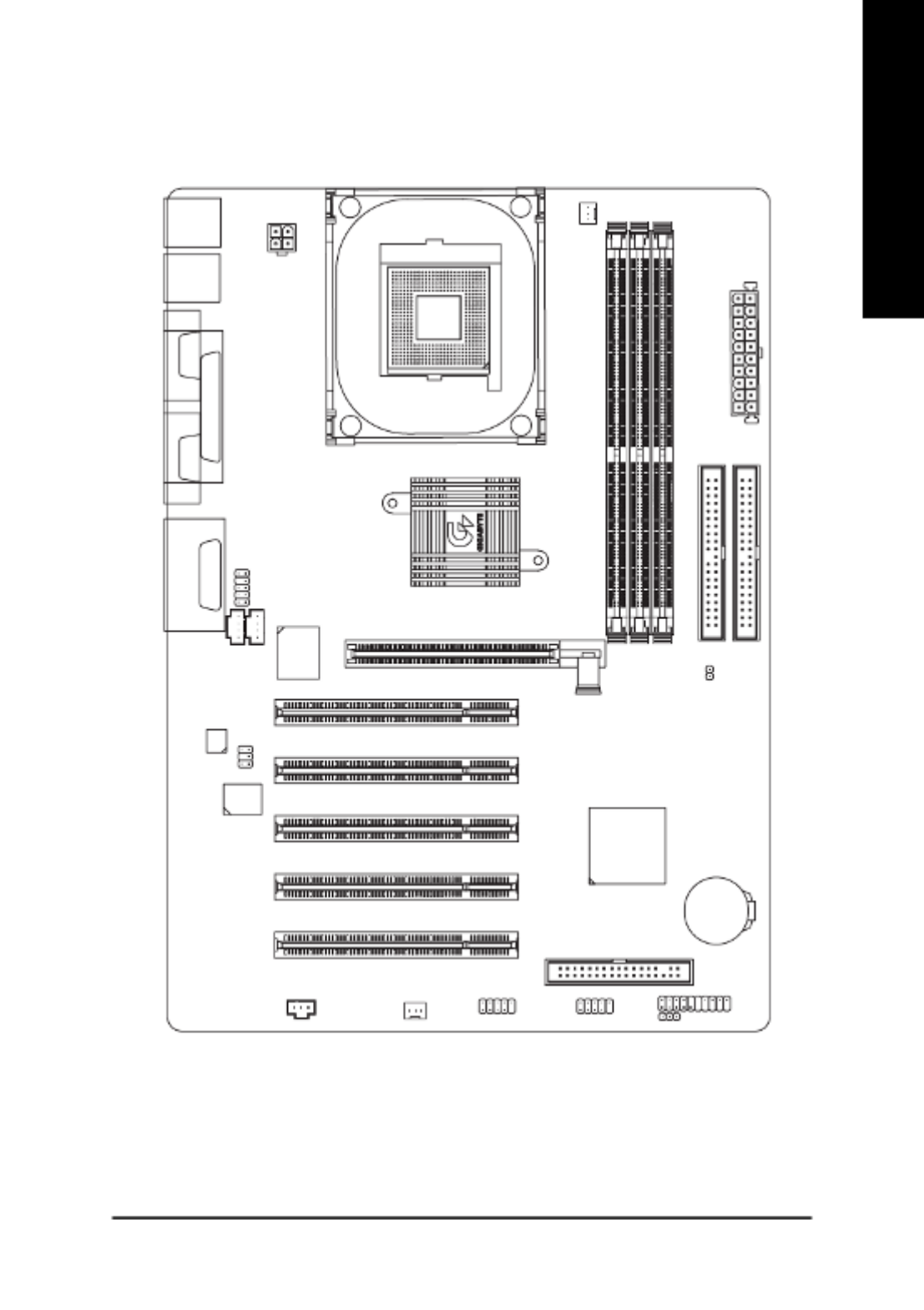
GA-8ST800 Motherboard Layout
CD_IN
GA-8ST800
KB_MS
COMA
LPTGAME
LINE_IN
LINE_OUTMIC_IN
USB
ATX_12V
SOCKET 478
CPU_FAN
ATX POWER
FDD
IDE1
IDE2
AGP
DDR2
DDR1
COMB
SiS 645DX
PWR_LED
BATTERY
PCI1
PCI2
PCI3
F_USB2
IT8705F
BIOS
CODEC
F_PANEL
SYS _FAN
SiS 962L
DDR3
PCI4
PCI5
F_USB1
SUR_CEN
SPDIF
F_AUDIO
AUX_IN
CI
- 8 -GA-8ST800 Series Motherboard
English
P4 Titan
-L
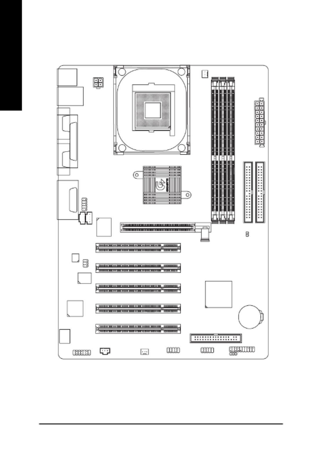
GA-8ST800-L Motherboard Layout
CD_IN
GA-8ST800
KB_MS
COMA
LPTGAME
LINE_IN
LINE_OUTMIC_IN USB
LAN
ATX_12V
SOCKET 478
CPU_FAN
ATX POWER
FDD
IDE1
IDE2
AGP
DDR2
DDR1
COMB
SiS 645DX
PWR_LED
BATTERY
PCI1
PCI2
PCI3
F_USB2
IT8705F
BIOS
CODEC
F_PANEL
SYS _FAN
SiS 962L
DDR3
PCI4
PCI5
F_USB1
SUR_CEN
SPDIF
F_AUDIO
AUX_IN
CI
MODEM
RTL
8101L

- 9 - Hardware Installation Process
English
To set up your computer, you must complete the following steps:
Step 1- Install the Central Processing Unit (CPU)
Step 2- Install memory modules
Step 3- Install expansion cards
Step 4- Connect ribbon cables, cabinet wires and power supply
Step 5- Setup BIOS software
Step 6- Install supporting software tools
Chapter 2 Hardware Installation Process
Step 2Step 4 Step 1
Step 3
Step 4
Step 4

- 10 -GA-8ST800 Series Motherboard
English
Step 1: Install the Central Processing Unit (CPU)
Step 1-1: CPU Installation
Please make sure the CPU type is supported by the motherboard.
If you do not match the CPU socket Pin 1 and CPU cut edge well, it will cause
improper installation. Please change the insert orientation.
Angling the
rod to 650
1. Angling the rod to 65-degree maybe feel a
kind of tight , and then continue pull the rod
to 90-degree when a noise “cough” made.
2. Pull the rod to the 90-degree directly .
Pin1 indicator
3. CPU Top View
Pin1 indicator
4. Locate Pin 1 in the socket and look
for a (golden) cut edge on the CPU
upper corner. Then insert the CPU
into the socket.
Socket
Actuation
Lever

- 11 - Hardware Installation Process
English
Step1-2: CPU Heat Sink Installation
1. Hook one end of the cooler bracket
to the CPU socket first.
2. Hook the other end of the cooler
bracket to the CPU socket.
Please use Intel approved cooling fan.
We recommend you to apply the thermal tape to provide better heat
conduction between your CPU and heatsink.
(The CPU cooling fan might stick to the CPU due to the hardening of the
thermal paste. During this condition if you try to remove the cooling fan, you
might pull the processor out of the CPU socket alone with the cooling fan,
and might damage the processor. To avoid this from happening, we suggest
you to either use thermal tape instead of thermal paste, or remove the cooling
fan with extreme caution.)
Make sure the CPU fan power cable is plugged in to the CPU fan connector,
this completes the installation.
Please refer to CPU heat sink user’s manual for more detail installation
procedure.

- 12 -GA-8ST800 Series Motherboard
English
DDR
1. The DIMM socket has a notch, so the DIMM memory
module can only fit in one direction.
2. Insert the DIMM memory module vertically into the
DIMM socket. Then push it down.
3. Close the plastic clip at both edges of the DIMM
sockets to lock the DIMM module.
Reverse the installation steps when you wish to
sremove the DIMM module.
Please note that the DIMM module can only fit in one direction due to the one
notches. Wrong orientation will cause improper installation. Please change
the insert orientation.
Step 2: Install memory modules
The motherboard has 3 dual inline memory module (DIMM) sockets. The BIOS will automatically
detects memory type and size. To install the memory module, just push it vertically into the DIMM
socket. The DIMM module can only fit in one direction due to the notch. Memory size can vary
between sockets.
Support Unbuffered DDR DIMM Sizes type:
64 Mbit (2Mx8x4 banks) 64 Mbit (1Mx16x4 banks) 128 Mbit (4Mx8x4 banks)
128 Mbit (2Mx16x4 banks) 256 Mbit (8Mx8x4 banks) 256 Mbit (4Mx16x4 banks)
512 Mbit (16Mx8x4 banks) 512 Mbit (8Mx16x4 banks)
- 13 - Hardware Installation Process
English
Step 3: Install expansion cards
1. Read the related expansion card’s instruction document before install the expansion card into the
computer.
2. Remove your computer’s chassis cover, necessary screws and slot bracket from the computer.
3. Press the expansion card firmly into expansion slot in motherboard.
4. Be sure the metal contacts on the card are indeed seated in the slot.
5. Replace the screw to secure the slot bracket of the expansion card.
6. Replace your computer’s chassis cover.
7. Power on the computer, if necessary, setup BIOS utility of expansion card from BIOS.
8. Install related driver from the operating system.
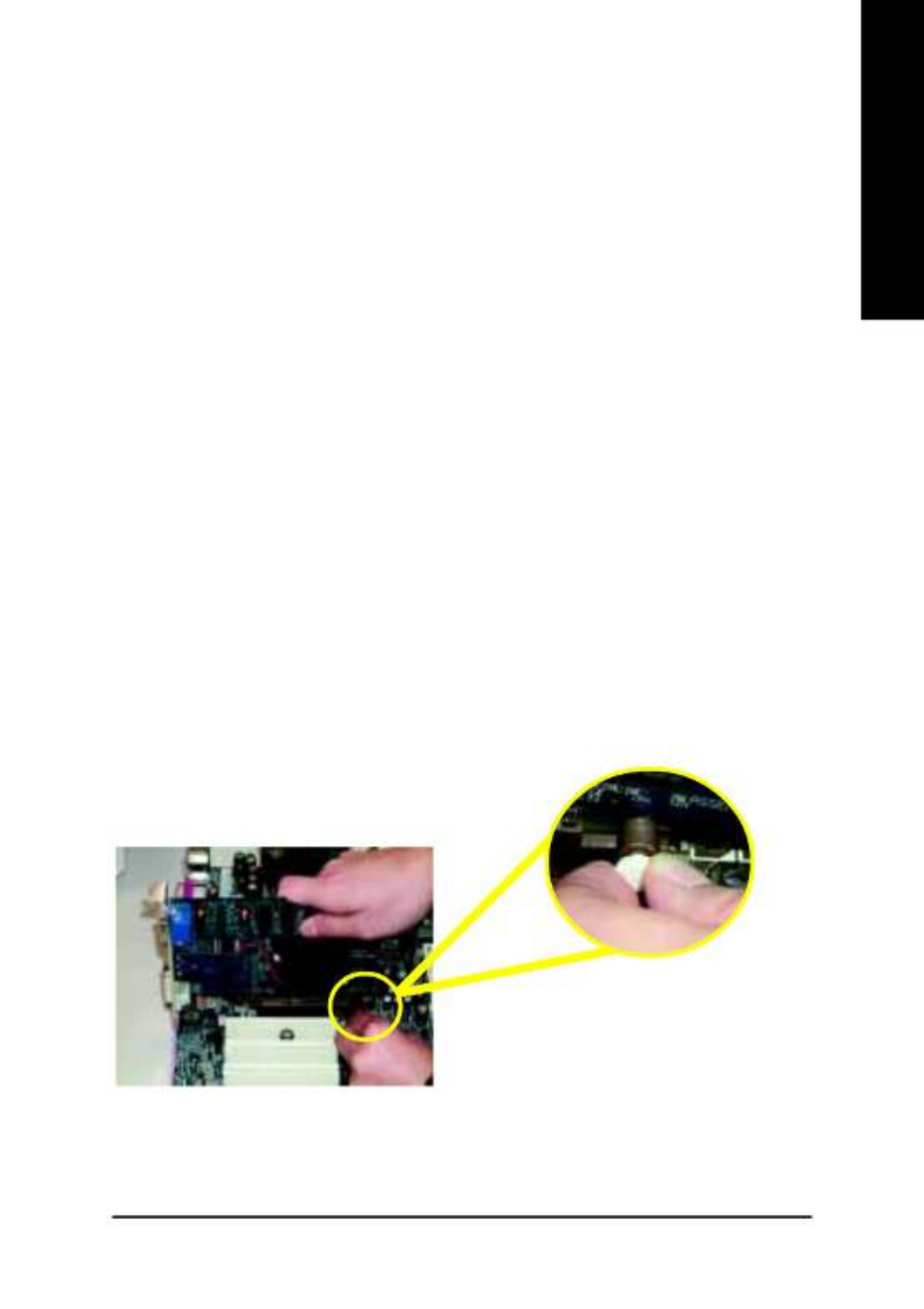
AGP Card
Please carefully pull out the small white-drawable
bar at the end of the AGP slot when you try to
install/ uninstall the AGP card. Please align the
AGP card to the onboard AGP slot and press firmly
down on the slot. Make sure your AGP card is
locked by the small white-drawable bar.
Established on the existing SDRAM industry infrastructure, DDR (Double Data Rate) memory is a
high performance and cost-effective solution that allows easy adoption for memory vendors, OEMs and
system integrators.
DDR memory is a sensible evolutionary solution for the PC industry that builds on the existing
SDRAM infrastructure, yet makes awesome advances in solving the system performance bottleneck by
doubling the memory bandwidth. DDR SDRAM will offer a superior solution and migration path from
existing SDRAM designs due to its availability, pricing and overall market support. PC2100 DDR
memory (DDR266) doubles the data rate through reading and writing at both the rising and falling edge of
the clock, achieving data bandwidth 2X greater than PC133 when running with the same DRAM clock
frequency. With peak bandwidth of 2.1GB per second, DDR memory enables system OEMs to build
high performance and low latency DRAM subsystems that are suitable for servers, workstations, high-
end PC's and value desktop SMA systems. With a core voltage of only 2.5 Volts compared to
conventional SDRAM's 3.3 volts, DDR memory is a compelling solution for small form factor desktops
and notebook applications.
DDR Introduction
- 14 -GA-8ST800 Series Motherboard
English
Step 4: Connect ribbon cables, cabinet wires and power
supply
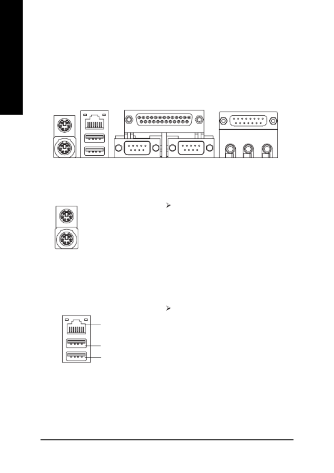
Step4-1: I/O Back Panel Introduction
!!!!
! PS/2 Keyboard and PS/2 Mouse Connector
This connector supports standard PS/2
keyboard and PS/2 mouse.
" USB / LAN* Connector
Before you connect your device(s) into USB
connector(s), please make sure your device(s)
such as USB keyboard,mouse, scanner, zip,
speaker...etc. Have a standard USB interface.
Also make sure your OS supports USB
controller. If your OS does not support USB
controller, please contact OS vendor for
possible patch or driver upgrade. For more
information please contact your OS or device(s)
vendors.
!
" # $
%
* For GA-8ST800-L Only.
PS/2 Mouse Connector
(6 pin Female)
PS/2 Keyboard Connector
(6 pin Female)
USB 0
USB 1
LAN*

- 15 - Hardware Installation Process
English
$ Game / MIDI Ports
% Audio Connectors
This connector supports joystick, MIDI
keyboard and other relate audio devices.
After install onboard audio driver, you may con-
nect speaker to Line Out jack, microphone to
MIC In jack. Device like CD-ROM,walkman
etc. can be connected to Line-In jack.
Please note:
You are able to use 2-/4-/6-channel audio feature
by S/W selection.
If you want to enable 6-channel function, you
have 2 choose for hardware connection.
Method1:
Connect "Front Speaker" to "Line Out"
Connect "Rear Speaker" to "Line In"
Connect "Center and Subwoofer" to "MIC Out ".
Method2:
You can refer to page 20, and contact your
nearest dealer for optional SUR_CEN cable.
# Parallel Port and Serial Ports (COMA/COMB)
This connector supports 2 standard COM ports
and 1 Parallel port. Device like printer can be
connected to Parallel port; mouse and modem
etc. can be connected to Serial ports.
MIC In
(Center and
Subwoofer)
Line Out
(Front Speaker)
Line In
(Rear Speaker)
If you want the detail information for 2-/4-/6-channel audio setup
installation, please refer to page 69.
Parallel Port
(25 pin Female)
COMA COMB
Serial Port (9 pin Male)
Joystick/ MIDI (15 pin Female)

- 16 -GA-8ST800 Series Motherboard
English
* Only for GA-8ST800-L.
Step 4-2: Connectors Introduction
5
152
13
11
12
14
3 1
6
9
6
8
17
10
1) CPU_FAN
2) SYS_FAN
3) ATX_12V
4) ATX POWER
5) FDD
6) IDE1 / IDE2
7) PWR_LED
8) F_PANEL
9) BATTERY
10) F_AUDIO
11) AUX_IN
12) CD_IN
13) SUR_CEN
14) SPDIF
15) F_USB1 / F_USB2
16) MODEM*
17) CI
4
16
- 17 - Hardware Installation Process
English
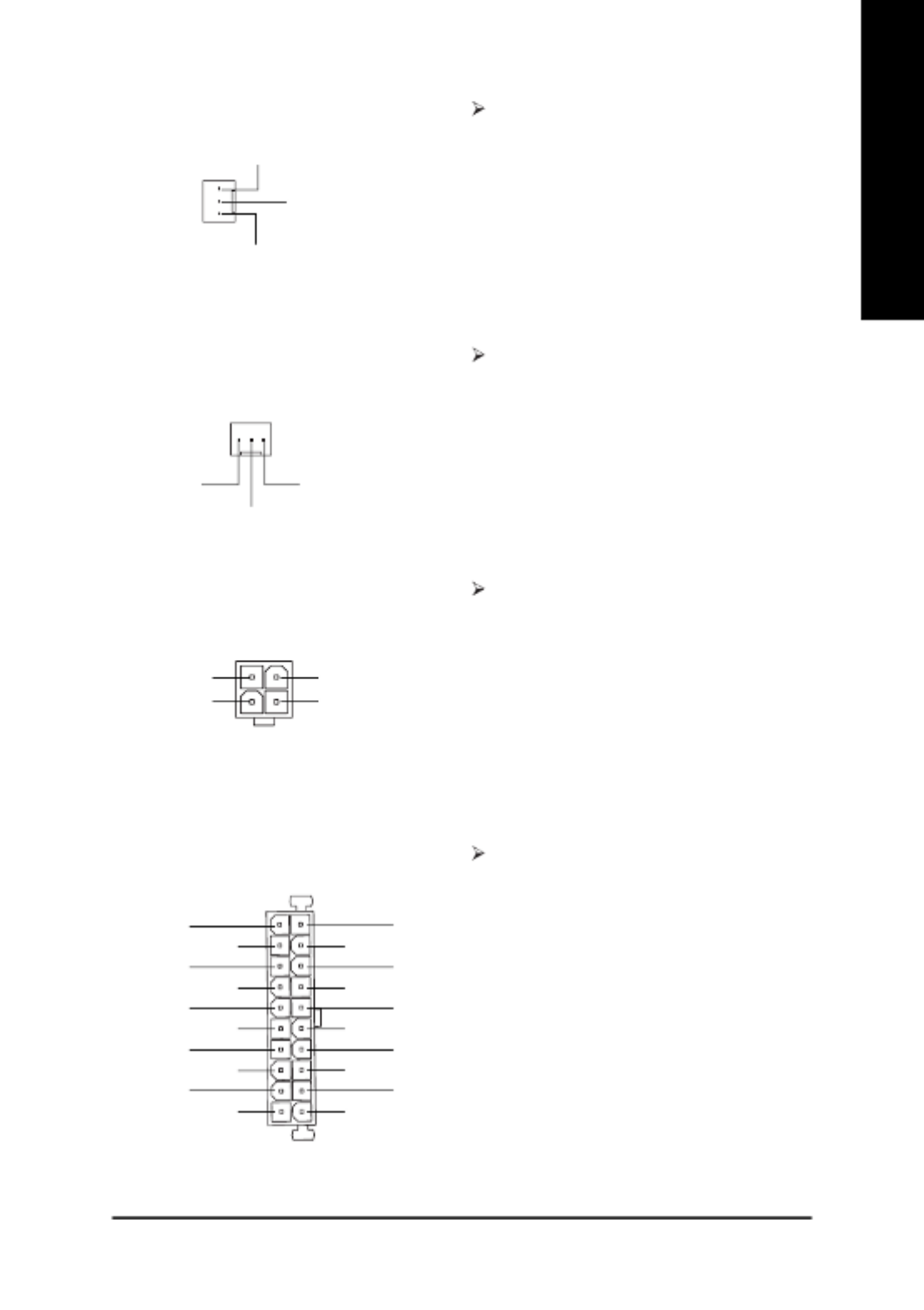
1) CPU_FAN (CPU Fan Connector) Please note, a proper installation of the CPU
cooler is essential to prevent the CPU from
running under abnormal condition or damaged
by overheating. The CPU fan connector
supports Max. current up to 600 mA.
2) SYS_FAN (System Fan Connector) This connector allows you to link with the
cooling fan on the system case to lower the
system temperature.
This connector (ATX_12V) supplies the CPU
operation voltage (Vcore).
If this " ATX_12V connector" is not connected,
system cannot boot.
3) ATX_12V ( +12V Power Connector)
4) ATX POWER (ATX Power Connector) AC power cord should only be connected to
your power supply unit after ATX power cable
and other related devices are firmly connected
to the motherboard.
20
1
PS-ON(Soft On/Off)
3.3V
GND
GND
GND
VCC -5V
-12V
GND
VCC
3.3V
3.3V
GND
GND
GND
VCC
VCC
+12V
5V SB(Stand by +5V)
Power Good
+12V
Sense
GND
1
1
+12V
Sense
GND
4
+12V
GND
+12V
GND
3
2 1

- 18 -GA-8ST800 Series Motherboard
English
6) IDE1/ IDE2 [IDE1 / IDE2 Connector (Primary/Secondary)]
Important Notice:
Please connect first hard disk to IDE1 and
connect CD-ROM to IDE2.
The red stripe of the ribbon cable must be the
same side with the Pin1.
IDE1IDE2
7) PWR_LED (Power LED Connector)
MPD+
MPD-
MPD-
1
PWR_LED is connect with the system power
indicator to indicate whether the system is
on/off. It will blink when the system enters
suspend mode.
If you use dual color LED, power LED will turn
to another color.
5) FDD (Floppy Connector)
1
Please connect the floppy drive ribbon cables
to FDD. It supports 360K,1.2M, 720K, 1.44M
and 2.88M bytes floppy disk types.
The red stripe of the ribbon cable must be the
same side with the Pin1.
2
33
34
1
2
3940
- 19 - Hardware Installation Process
English
8) F_PANEL (2x10 Pins Connector)
Please connect the power LED, PC speaker, reset switch and power switch etc. of your chassis
front panel to the F_PANEL connector according to the pin assignment above.
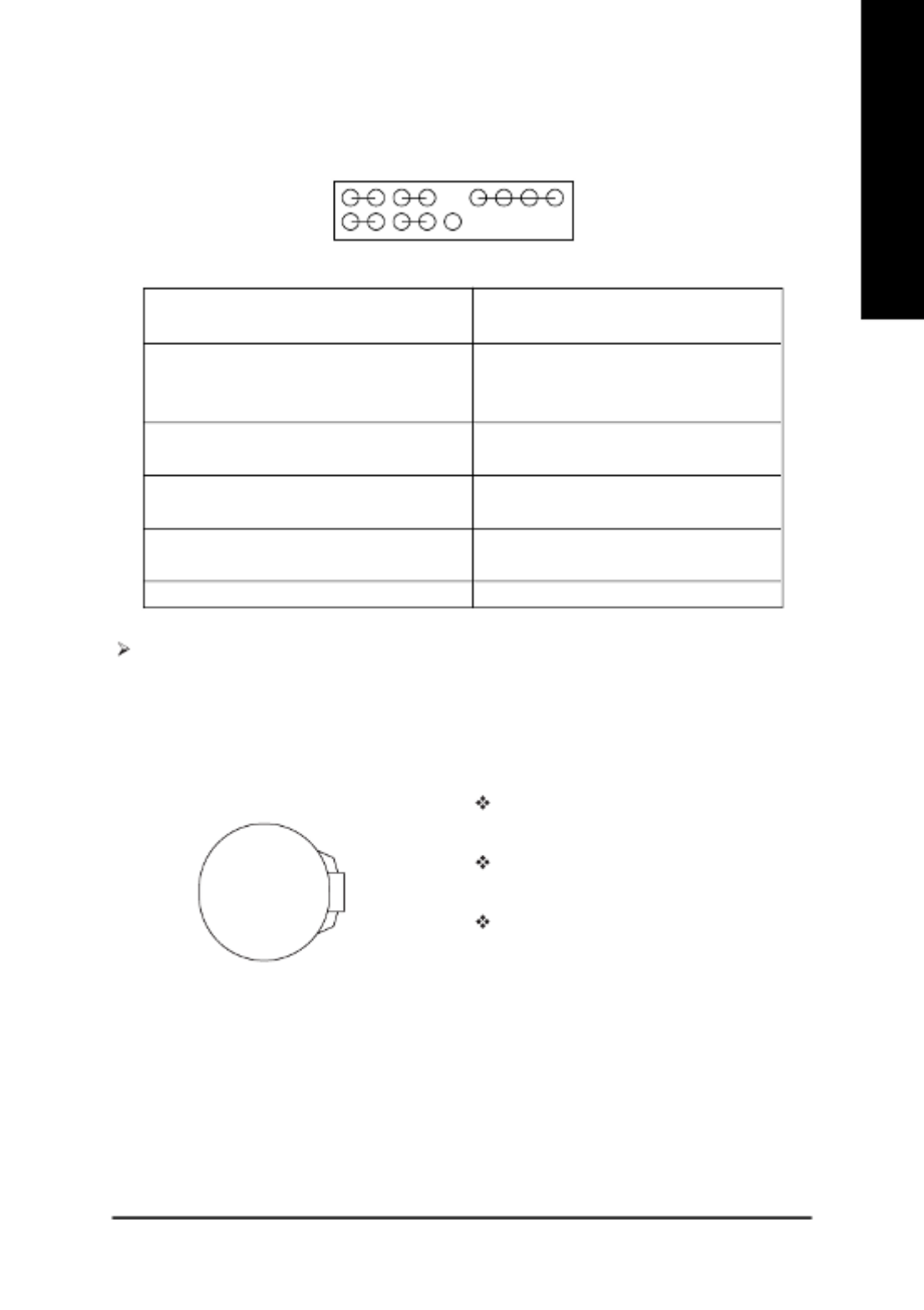
9) BATTTERY
+
CAUTION
Danger of explosion if battery is incorrectly
replaced.
Replace only with the same or equivalent
type recommended by the manufacturer.
Dispose of used batteries according to the
manufacturer’s instructions.
HD (IDE Hard Disk Active LED) Pin 1: LED anode(+)
(Blue) Pin 2: LED cathode(-)
SPK (Speaker Connector) Pin 1: VCC(+)
(Amber) Pin 2- Pin 3: NC
Pin 4: Data(-)
RES (Reset Switch) Open: Normal Operation
(Green) Close: Reset Hardware System
PW (Soft Power Connector) Open: Normal Operation
(Red) Close: Power On/Off
MSG(Message LED/Power/Sleep LED) Pin 1: LED anode(+)
(Yellow) Pin 2: LED cathode(-)
NC (Purple) N C
N C
HD+ MSG+
2 20
119
PW-
PW+RES-
SPK-
1
1
RES+
HD- MSG-
1
SPK+
1
1
If you want to erase CMOS...
1. Turn OFF the computer and unplug the power cord.
2. Remove the battery, wait for 30 second.
3. Re-install the battery.
4. Plug the power cord and turn ON the computer.

- 20 -GA-8ST800 Series Motherboard
English
10) F_AUDIO (Front Audio Connector) If you want to use Front Audio connector, you
must remove 5-6, 9-10 Jumper.
In order to utilize the front audio header, your
chassis must have front audio connector. Also
please make sure the pin assigment on the
cable is the same as the pin assigment on the
MB header. To find out if the chassis you are
buying support front audio connector, please
contact your dealer.
12) CD_IN (CD Audio In Connector) Connect CD-ROM or DVD-ROM audio out to
the connector.
11) AUX_IN (AUX In Connector) Connect other device (such as PCI TV Tunner
audio out) to the connector.
13) SUR_CEN (Surround Center Connector)
Please contact your nearest dealer for optional
SUR_CEN cable.
Front Audio (L)
Reserved
Front Audio (R)
MIC
REF
Rear Audio (L)
Rear Audio (R)
GND
Power 12
910
SUR OUT(L)
GND
CENTER_OUT
SUR OUT(R)
BASS_OUT
12
56
1
AUX_L
GND
AUX_R
1
CD_L
GND
CD_R

- 21 - Hardware Installation Process
English
14) SPDIF (SPDIF) The SPDIF output is capable of providing
digital audio to external speakers or
compressed AC3 data to an external Dolby
Digital Decoder. Use this feature only when
your stereo system has digital input function.
6 Channel output : A "S/PDIF output" connec-
tor is available on the motherboard. Please
contact your nearest dealer for optional SPDIF
cable.
Be careful with the polarity of the front USB
connector. Check the pin assignment while
you connect the front USB cable. Please
contact your nearest dealer for optional front
USB 2.0 cable.
15) F_USB1 / F_USB2 (Front USB Connector, Yellow)
17) CI (Case Open) This 2-pin connector allows your system to
enable or disable the "Case Open" item in
BIOS, if the system case begin remove.
Please contact your nearest dealer for optional
Modem card.
16) MODEM*
1
2
13
14
VAUX33
+12V
N C
VDD33
VCC
AC DOUT
AC DIN
AC OUT
GND
N C
AC BCK
AC SYNC
AC RSTB
* Only for GA-8ST800-L.
VCC
SPDIF Out
GND
1
1Signal GND
1
2
9
10
GND
USB Dy+
USB Over Current
Power
USB Dy-
USB Dx+
GND
USB Dx-
Power

- 22 -GA-8ST800 Series Motherboard
English

- 23 - BIOS Setup
English
< > Move to previous item
< > Move to next item
< > Move to the item in the left hand
< > Move to the item in the right hand
<Enter> Select Item
<Esc> Main Menu - Quit and not save changes into CMOS Status Page Setup Menu and
Option Page Setup Menu - Exit current page and return to Main Menu
<+/PgUp> Increase the numeric value or make changes
<-/PgDn> Decrease the numeric value or make changes
<F1> General help, only for Status Page Setup Menu and Option Page Setup Menu
<F2> Item Help
<F3> Reserved
<F4> Reserved
<F5> Restore the previous CMOS value from CMOS, only for Option Page Setup Menu
<F6> Load the file-safe default CMOS value from BIOS default table
<F7> Load the Optimized Defaults
<F8> Q-Flash function
<F9> Reserved
<F10> Save all the CMOS changes, only for Main Menu
BIOS Setup is an overview of the BIOS Setup Program. The program that allows users to modify the
basic system configuration. This type of information is stored in battery-backed CMOS RAM so that it
retains the Setup information when the power is turned off.
Chapter 3 BIOS Setup
ENTERING
Powering ON the computer and pressing <Del> immediately will allow you to enter Setup. If you require
more advanced BIOS settings, please go to "Advanced BIOS" setting menu. To enter Advanced BIOS
setting menu, press "Ctrl+F1" key on the BIOS screen.
CONTROL
SETUP
KEYS

- 24 -GA-8ST800 Series Motherboard
English
l St ndard CMOS Featu sa re
This setup page includes all the items in standard compatible BIOS.
l Adv nced BIOS Featu sa re
This setup page includes all the items of Award special enhanced features.
l Integrated Per pheralsi
This setup page includes all onboard peripherals.
Main Menu
The on-line description of the highlighted setup function is displayed at the bottom of the screen.
Status Page Setup Menu / Option Page Setup Menu
Press F1 to pop up a small help window that describes the appropriate keys to use and the possible
selections for the highlighted item. To exit the Help Window press <Esc>.
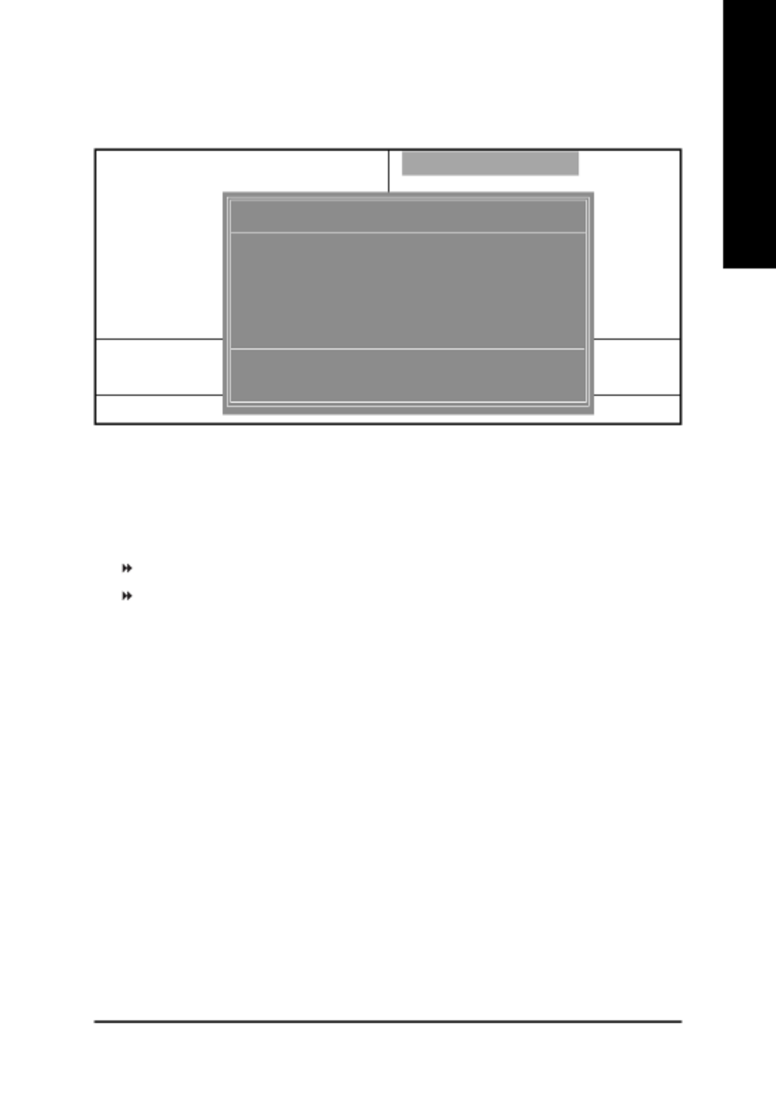
The Main Menu (For example: BIOS Ver. : F1)
Once you enter Award BIOS CMOS Setup Utility, the Main Menu (Figure 1) will appear on the
screen. The Main Menu allows you to select from eight setup functions and two exit choices. Use
arrow keys to select among the items and press <Enter> to accept or enter the sub-menu.
GETTING HELP
Figure 1: Main Menu
CMOS Setup Utility-Copyright (C) 1984-2002 Award Software
! Standard CMOS Features Top Performance
! Advanced BIOS Features Load Fail-Safe Defaults
! Integrated Peripherals Load Optimized Defaults
! Power Management Setup Set Supervisor Password
! PnP/PCI Configurations Set User Password
! PC Health Status Save & Exit Setup
! Frequency/Voltage Control Exit Without Saving
ESC:Quit "#$%:Select Item
F8: Q-Flash F10: Save & Exit Setup
Time, Date, Hard Disk Type...

- 25 - BIOS Setup
English
l Power nag Setup Ma ement
This setup page includes all the items of Green function features.
l PnP/PCI Configurations
This setup page includes all the configurations of PCI & PnP ISA resources.
l PC Health Status
This setup page is the System auto detect Temperature, voltage, fan, speed.
l F equency/ oltage Cont olr V r
This setup page is control CPU’s clock and frequency ratio.
l Top Per orm ncef a
If you wish to maximize the performance of your system, set "Top Performance" as "Enabled".
l Lo d Fail-SafeDefaultsa
Fail-Safe Defaults indicates the value of the system parameters which the system would
be in safe configuration.
l Lo d Opt Defaultsa imized
Optimized Defaults indicates the value of the system parameters which the system would
be in best performance configuration.
l Set Supervisor password
Change, set, or disable password. It allows you to limit access to the system and Setup,
or just to Setup.
l Set User password
Change, set, or disable password. It allows you to limit access to the system.
l Save & Exit Setup
Save CMOS value settings to CMOS and exit setup.
l Exit Without Saving
Abandon all CMOS value changes and exit setup.

- 26 -GA-8ST800 Series Motherboard
English
Standard CMOS Features
CMOS Setup Utility-Copyright (C) 1984-2002 Award Software
Standard CMOS Features
Date (mm:dd:yy) Tue, Nov 19 2002 Item Help
Time (hh:mm:ss) 17:56:23 Menu Level &
Change the day, month,
!IDE Primary Master [None] year
!IDE Primary Slave [None]
!IDE Secondary Master [None] <Week>
!IDE Secondary Slave [None] Sun. to Sat.
Drive A [1.44M, 3.5"] <Month>
Drive B [None] Jan. to Dec.
Floppy 3 Mode Support [Disabled]
<Day>
Halt On [All, But Keyboard] 1 to 31 (or maximum
allowed in the month)
Base Memory 640K
Extended Memory 130048K <Year>
Total Memory 131072K 1999 to 2098
"#$ % : Move Enter:Select +/-/PU/PD:Value F10:Save ESC:Exit F1:General Help
F5:Previous Values F6:Fail-Safe Defaults F7:Optimized Defaults
Figure 2: Standard CMOS Features
Date
The date format is <week>, <month>, <day>, <year>.
Week The week, from Sun. to Sat., determined by the BIOS and is display only
Month The month, Jan. Through Dec.
Day The day, from 1 to 31 (or the maximum allowed in the month)
Year The year, from 1999 through 2098

- 27 - BIOS Setup
English
Time
The times format in <hour> <minute> <second>. The time is calculated base on the 24-hour
military-time clock. For example, 1 p.m. is 13:00:00.
IDE Primary Master, Slave / IDE Secondary Master, Slave
The category identifies the types of hard disk from drive C to F that has been installed in the
computer. There are two types: auto type, and manual type. Manual type is user-definable; Auto type
which will automatically detect HDD type.
Note that the specifications of your drive must match with the drive table. The hard disk will not work
properly if you enter improper information for this category.
If you select User Type, related information will be asked to enter to the following items. Enter the
information directly from the keyboard and press <Enter>. Such information should be provided in the
documentation form your hard disk vendor or the system manufacturer.
Cylinder Number of cylinders
Head Number of heads
Precomp Write precomp
Landing Zone Landing zone
Sector Number of sectors
If a hard disk has not been installed select NONE and press <Enter>.
Drive A / Drive B
The category identifies the types of floppy disk drive A or drive B that has been installed in the
computer.
None No floppy drive installed
360K, 5.25" 5.25 inch PC-type standard drive; 360K byte capacity.
1.2M, 5.25" 5.25 inch AT-type high-density drive; 1.2M byte capacity
(3.5 inch when 3 Mode is Enabled).
720K, 3.5" 3.5 inch double-sided drive; 720K byte capacity
1.44M, 3.5" 3.5 inch double-sided drive; 1.44M byte capacity.
2.88M, 3.5" 3.5 inch double-sided drive; 2.88M byte capacity.

- 28 -GA-8ST800 Series Motherboard
English
Floppy 3 Mode Support (for Japan Area)
Disabled Normal Floppy Drive. (Default value)
Drive A Enable Drive A is 3 mode Floppy Drive.
Drive B Enable Drive B is 3 mode Floppy Drive.
Both Enable Drive A & B are 3 mode Floppy Drives.
Halt on
The category determines whether the computer will stop if an error is detected during power up.
All Errors Whenever the BIOS detects a non-fatal error the system will be stopped.
NO Errors The system boot will not stop for any error that may be detected and you
will be prompted.
All, But Keyboard The system boot will not stop for a keyboard error; it will stop for all other
errors. (Default value)
All, But Diskette The system boot will not stop for a disk error; it will stop for all other errors.
All, But Disk/Key The system boot will not stop for a keyboard or disk error; it will stop for all
other errors.
Memory
The category is display-only which is determined by POST (Power On Self Test) of the BIOS.
Base Memory
The POST of the BIOS will determine the amount of base (or conventional) memory
installed in the system.
The value of the base memory is typically 512K for systems with 512K memory installed on
the motherboard, or 640K for systems with 640K or more memory installed on the motherboard.
Extended Memory
The BIOS determines how much extended memory is present during the POST.
This is the amount of memory located above 1MB in the CPU's memory address map.

- 30 -GA-8ST800 Series Motherboard
English
USB-CDROM Select your boot device priority by USB-CDROM.
USB-HDD Select your boot device priority by USB-HDD.
LAN Select your boot device priority by LAN.
Disabled Select your boot device priority by Disabled.
Boot Up Floppy Seek
During POST, BIOS will determine the floppy disk drive installed is 40 or 80 tracks. 360K type is
40 tracks 720K, 1.2M and 1.44M are all 80 tracks.
Disabled BIOS will not search for the type of floppy disk drive by track number. Note
that there will not be any warning message if the drive installed is 360 K.
(Default value)
Enabled BIOS searches for floppy disk drive to determine it is 40 or 80 tracks. Note
that BIOS can not tell from 720 K, 1.2 M or 1.44 M drive type as they are
all 80tracks.
Password Check
System The system can not boot and can not access to Setup page will be denied
if the correct password is not entered at the prompt.
Setup The system will boot, but access to Setup will be denied if the correct
password is not entered at the prompt. (Default value)
CPU Hyper-Threading
#
Disabled Disable CPU Hyper Threading.
Enabled Enable CPU Hyper Threading Feature. Please note that this feature is only
working for operating system with multi processors mode supported.
(Default value)

- 31 - BIOS Setup
English
Integrated Peripherals
Figure 4: Integrated Peripherals
IDE1 Conductor Cable
Auto Will be automatically detected by BIOS. (Default Value)
ATA66/100/133 Set IDE1 Conductor Cable to ATA66/100/133 (Please make sure your IDE
device and cable is compatible with ATA66/100/133).
ATA33 Set IDE1 Conductor Cable to ATA33 (Please make sure your IDE device
and cable is compatible with ATA33).
IDE1 Conductor Cable [Auto]
IDE2 Conductor Cable [Auto]
On-Chip Primary PCI IDE [Enabled]
On-Chip Secondary PCI IDE [Enabled]
AC97 Audio [Enabled]
USB Controller [Enabled]
USB Legacy Support [Disabled]
Onboard LAN device* [Enabled]
Init Display First [AGP]
Onboard Serial Port 1 [3F8/IRQ4]
Onboard Serial Port 2 [2F8/IRQ3]
Onboard Parallel Port [378/IRQ7]
Parallel Port Mode [SPP]
x ECP Mode Use DMA 3
Game Port Address [201]
Midi Port Address [330]
Midi Port IRQ [10]
Item Help
Menu Level &
[Auto]
Auto-detect IDE
cable type
[ATA66/100/133]
Set Conductor cable
to ATA66/100/133(80
-pins)
[ATA33]
Set Conductor cable
to ATA33(40-pins)
CMOS Setup Utility-Copyright (C) 1984-2002 Award Software
Integrated Peripherals
" # $ %: Move Enter:Select +/-/PU/PD:Value F10:Save ESC:Exit F1:General Help
F5:Previous Values F6:Fail-Safe Defaults F7:Optimized Defaults
* Only for GA-8ST800-L.

- 32 -GA-8ST800 Series Motherboard
English
IDE2 Conductor Cable
Auto Will be automatically detected by BIOS. (Default Value)
ATA66/100/133 Set IDE2 Conductor Cable to ATA66/100/133 (Please make sure your IDE
device and cable is compatible with ATA66/100/133).
ATA33 Set IDE2 Conductor Cable to ATA33 (Please make sure your IDE device
and cable is compatible with ATA33).
On-Chip Primary PCI IDE
Disabled Disable onboard 1st channel IDE port.
!Enabled Enable onboard 1st channel IDE port. (Default value)
On-Chip Secondary PCI IDE
Disabled Disable onboard 2nd channel IDE port.
Enabled Enable onboard 2nd channel IDE port. (Default value)
AC97 Audio
Enabled Enable auto detect onboard AC'97 audio. (Default value)
Disabled Disable this function.
USB Controller
Disable this function if you are not using onboard USB feature.
Disabled Disable USB Controller.
Enabled Enable USB Controller. (Default value)
USB Legacy Support
When USB keyboard or mouse is installed, please set at Enabled.
Disabled Disable USB keyboard or mouse Support. (Default value)
!Enabled Enable USB keyboard or mouse support.
Onboard LAN device*
Enabled Enable Onboard Lan Chip function. (Default Value)
Disabled Disable this function.
* Only for GA-8ST800-L.

- 33 - BIOS Setup
English
Init Display First
Select the first initation of the monitor display from AGP or PCI VGA card.
PCI Set Init Display First to PCI.
AGP Set Init Display First to AGP. (Default value)
Onboard Serial Port 1
Disabled Disable onboard Serial port 1.
3F8/IRQ4 Enable onboard Serial port 1 and address is 3F8, using IRQ4. (Default value)
2F8/IRQ3 Enable onboard Serial port 1 and address is 2F8, using IRQ3.
3E8/IRQ4 Enable onboard Serial port 1 and address is 3E8, using IRQ4.
2E8/IRQ3 Enable onboard Serial port 1 and address is 2E8, using IRQ3.
Auto BIOS will automatically setup the port 1 address.
Onboard Serial Port 2
Disabled Disable onboard Serial port 2.
3F8/IRQ4 Enable onboard Serial port 2 and address is 3F8, using IRQ4.
2F8/IRQ3 Enable onboard Serial port 2 and address is 2F8, using IRQ3. (Default value)
3E8/IRQ4 Enable onboard Serial port 2 and address is 3E8, using IRQ4.
2E8/IRQ3 Enable onboard Serial port 2 and address is 2E8, using IRQ3.
Auto BIOS will automatically setup the port 2 address.
Onboard Parallel port
This feature allows you to select from a given set of parameters if the parallel port uses the onboard
I/O controller.
Disabled Disable onboard LPT port.
378/IRQ7 Enable onboard LPT port and address is 378, using IRQ7. (Default Value)
278/IRQ5 Enable onboard LPT port and address is 278, using IRQ5.
3BC/IRQ7 Enable onboard LPT port and address is 3BC, using IRQ7.

- 34 -GA-8ST800 Series Motherboard
English
Parallel Port Mode
This feature allows you to connect with an advanced printer via the port mode it supports.
SPP Using Parallel port as Standard Parallel Port. (Default Value)
EPP Using Parallel port as Enhanced Parallel Port.
ECP Using Parallel port as Extended Capabilities Port.
ECP+EPP Using Parallel port as ECP & EPP mode.
ECP Mode Use DMA
This feature allows you to select Direct Memory Access(DMA) channel if the ECP mode selected.
1 Set ECP Mode Use DMA to 1.
3 Set ECP Mode Use DMA to 3. (Default Value)
Game Port Address
This feature allows you to select the game port address or disable it.
Disabled Disable this function.
201 Set Game port address to 201. (Default Value)
209 Set Game port address to 209.
Midi Port Address
This feature allows you to select the Midi port address or disable it.
Disabled Disable this function.
300 Set Midi port address to 300.
330 Set Midi port address to 330.(Default Value)
Midi Port IRQ
5 Set Midi Port IRQ to 5.
10 Set Midi Port IRQ to 10. (Default Value)

- 35 - BIOS Setup
English
Power Management Setup
CMOS Setup Utility-Copyright (C) 1984-2002 Award Software
Power Management Setup
ACPI Suspend Type [S1(POS)] Item Help
Soft-Off by PWR_BTTN [Off] Menu Level &
System After AC Back [Off] [S1]
IRQ [3-7, 9-15], NMI [Enabled] Set suspend type to
ModemRingOn [Enabled] Power On Suspend under
PME Event Wake Up [Enabled] ACPI OS
Power On by Keyboard [Disabled]
Power On by Mouse [Disabled] [S3]
Resume by Alarm [Disabled] Set suspend type to
x Month Alarm NA Suspend to RAM under
x Day (of Month) 0 ACPI OS
x Time (hh:mm:ss) 0 : 0 : 0
Power LED in S1/S3 state [Blinking]
"#$%: Move Enter:Select +/-/PU/PD:Value F10:Save ESC:Exit F1:General Help
F5:Previous Values F6:Fail-Safe Defaults F7:Optimized Defaults
Figure 5: Power Management Setup
ACPI Suspend Type
S1(POS) Set ACPI suspend type to S1. (Default Value)
S3(STR) Set ACPI suspend type to S3.
Soft-off by PWR_BTTN
Off User can press Power button to power off system instantly. (Default Value)
Suspend User can press Power button for 4 seconds to power off system. System will
enter suspend mode if button is pressed less than 4 seconds.

- 37 - BIOS Setup
English
Power On by Mouse
Disabled Disable this function. (Default Value)
Enabled Enable Power On by move or click mouse function.
Resume by Alarm
You can set "Resume by Alarm" item to enabled and key in Data/time to power on system.
Disabled Disable this function. (Default Value)
Enabled Enable alarm function to POWER ON system.
If RTC Alarm Lead To Power On is Enabled.
Month Alarm : NA, 1~12
Day (of Month) : 1~31
Time (hh : mm : ss) : (0~23) : (0~59) : (0~59)
Power LED in S1/S3 state
Blinking In standby mode(S1), power LED will blink. (Default Value)
Dual/OFF In standby mode(S1):
a. If use single color LED, power LED will turn off.
b. If use dual color LED, power LED will turn to another color.

- 40 -GA-8ST800 Series Motherboard
English
Current System / CPU Temperature
!Detect System/CPU temperature automatically.
Current CPU/SYSTEM FAN Speed (RPM)
Detect CPU/System Fan speed status automatically.
CPU Warning Temperature
Disabled Don't monitor CPU's temperature. (Default value)
60°/140°F Alarm when CPU current temperature over than 60°/140°F.
70°/158°F Alarm when CPU current temperature over than 70°/158°F.
80°/176°F Alarm when CPU current temperature over than 80°/176°F.
90°/194°F Alarm when CPU current temperature over than 90°/194°F.
CPU FAN Fail Warning
Disabled Fan Warning function disable. (Default value)
Enabled Enalbe FAN warning alarm when FAN stops.
SYSTEM FAN Fail Warning
Disabled Fan Warning function disable. (Default value)
Enabled Enalbe FAN warning alarm when FAN stops.

- 42 -GA-8ST800 Series Motherboard
English
AGP Clock (MHz)
Please set AGP Clock according to your requirement.
! Incorrect using it may cause your system broken. For power End-User use only!
PCI Clock (MHz)
Please set PCI Clock according to your requirement.
! Incorrect using it may cause your system broken. For power End-User use only!
- 43 - BIOS Setup
English
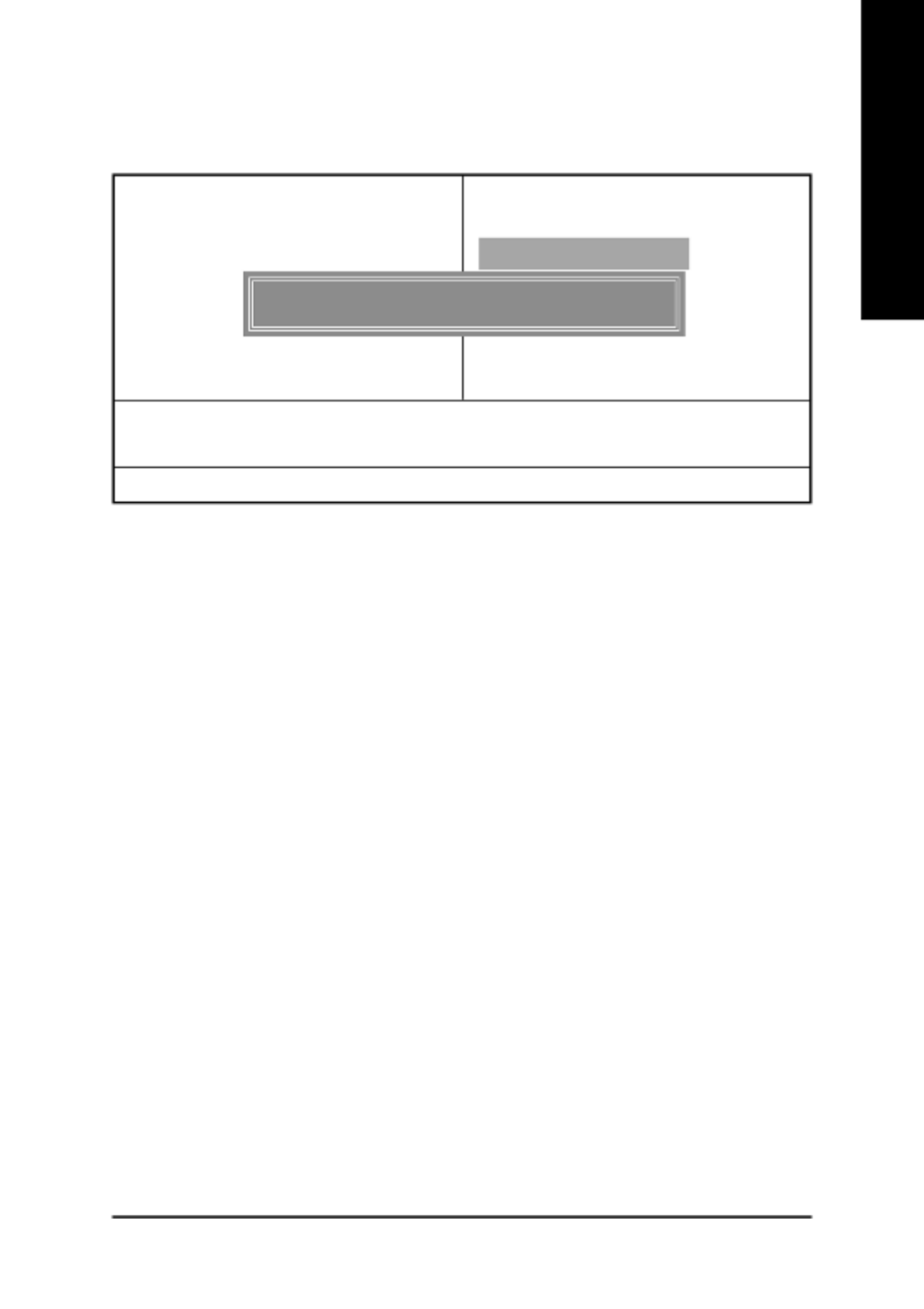
Top Performance
Top Performance
If you wish to maximize the performance of your system, set "Top Performance" as "Enabled".
Disabled Disable this function. (Default Value)
Enabled Enable Top Performance function.
!You must check whether your RAM, CPU support over clock when you set "Top Performance" to
"Enabled".
Figure 9: Top Performance
CMOS Setup Utility-Copyright (C) 1984-2002 Award Software
!Standard CMOS Features Top Performance
!Advanced Chipset Features Load Fail-Safe Defaults
!Integrated Pe
!Power Mana
!PnP/PCI Con
!PC Health St
!Frequency/V
ESC:Quit
F8: Q-Flash
Top Performance
Disabled...................[ "]
Enabled................... [ ]
" # : Move ENTER: Accept
ESC: Abort

- 44 -GA-8ST800 Series Motherboard
English
Load Fail-Safe Defaults
Load Fail-Safe Defaults
Fail-Safe defaults contain the most appropriate values of the system parameters that allow mini-
mum system performance.
Figure 10: Load Fail-Safe Defaults
CMOS Setup Utility-Copyright (C) 1984-2002 Award Software
!Standard CMOS Features Top Performance
!Advanced Chipset Features Load Fail-Safe Defaults
!Integrated Peripherals Load Optimized Defaults
!Power Man
!PnP/PCI C
!PC Health Status Save & Exit Setup
!Frequency/Voltage Control Exit Without Saving
ESC:Quit "#$%:Select Item
F8: Q-Flash F10:Save & Exit Setup
Load Fail-Safe Defaults
Load Fail-Safe Defaults (Y/N) ? N
- 45 - BIOS Setup
English
Load Optimized Defaults
Load Optimized Defaults
Selecting this field loads the factory defaults for BIOS and Chipset Features which the system
automatically detects.
Figure 11: Load Optimized Defaults
CMOS Setup Utility-Copyright (C) 1984-2002 Award Software
!Standard CMOS Features Top Performance
!Advanced BIOS Features Load Fail-Safe Defaults
!Integrated Peripherals Load Optimized Defaults
!Power Ma
!PnP/PCI
!PC Health Status Save & Exit Setup
!Frequency/Voltage Control Exit Without Saving
ESC:Quit "#$%:Select Item
F8: Q-Flash F10:Save & Exit Setup
Load Optimized Defaults
Load Optimized Defaults (Y/N) ? N
- 46 -GA-8ST800 Series Motherboard
English
Set Supervisor/User Password
When you select this function, the following message will appear at the center of the screen to
assist you in creating a password.
Type the password, up to eight characters, and press <Enter>. You will be asked to confirm the
password. Type the password again and press <Enter>. You may also press <Esc> to abort the
selection and not enter a password.
To disable password, just press <Enter> when you are prompted to enter password. A message
"PASSWORD DISABLED" will appear to confirm the password being disabled. Once the password is
disabled, the system will boot and you can enter Setup freely.
The BIOS Setup program allows you to specify two separate passwords:
SUPERVISOR PASSWORD and a USER PASSWORD. When disabled, anyone may access all
BIOS Setup program function. When enabled, the Supervisor password is required for entering the BIOS
Setup program and having full configuration fields, the User password is required to access only basic
items.
If you select "System" at "Password Check" in Advance BIOS Features Menu, you will be
prompted for the password every time the system is rebooted or any time you try to enter Setup Menu.
If you select "Setup" at "Password Check" in Advance BIOS Features Menu, you will be prompted
only when you try to enter Setup.
Figure 12: Password Setting
CMOS Setup Utility-Copyright (C) 1984-2002 Award Software
!Standard CMOS Features Top Performance
!Advanced BIOS Features Load Fail-Safe Defaults
!Integrated Peripherals Load Optimized Defaults
!Power Man
!PnP/PCI C
!PC Health Status Save & Exit Setup
!Frequency/Voltage Control Exit Without Saving
ESC:Quit "#$%:Select Item
F8: Q-Flash F10:Save & Exit Setup
Change/Set/Disable Password
Enter Password:

- 48 -GA-8ST800 Series Motherboard
English
Exit Without Saving
Type "Y" will quit the Setup Utility without saving to RTC CMOS.
Type "N" will return to Setup Utility.
Figure 14: Exit Without Saving
CMOS Setup Utility-Copyright (C) 1984-2002 Award Software
!Standard CMOS Features Top Performance
!Advanced BIOS Features Load Fail-Safe Defaults
!Integrated Peripherals Load Optimized Defaults
!Power Management Setup Set Supervisor Password
!PnP/PCI Co
!PC Health S
!Frequency/Voltage Control Exit Without Saving
ESC:Quit "#$%:Select Item
F8: Q-Flash F10:Save & Exit Setup
Abandon all Data
Quit Without Saving (Y/N) ? N
Product specificaties
| Merk: | Gigabyte |
| Categorie: | Moederbord |
| Model: | GA-8ST800 |
| Breedte: | 304 mm |
| Diepte: | 200 mm |
| Type stroombron: | ATX |
| Aantal USB 2.0-poorten: | 2 |
| Microfoon, line-in ingang: | Ja |
| Hoofdtelefoonuitgangen: | 3 |
| Meegeleverde software: | Norton Internet Security\nNorton Anti-Virus\nNorton Personal Firewall\nNorton Privacy Control\nNorton Parental Control\nNorton Spam Alert \nGIGABYTE Windows Utility Manager\nAdobe Acrobat Reader |
| Processor socket: | Socket 478 |
| Processorfabrikant: | Intel |
| Maximum intern geheugen: | 3 GB |
| Audio-uitgangskanalen: | 6.1 kanalen |
| Meegeleverde drivers: | Ja |
| Ondersteunde opslagstationinterfaces: | Parallel ATA |
| PS/2 poort(en): | 1 |
| Component voor: | PC |
| PCI-slots: | 5 |
| Compatibele processors: | Intel® Pentium® 4 |
| Ondersteunde geheugen types: | DDR-SDRAM |
| Ondersteuning voor processor FSB: | 533 MHz |
| Moederbord chipset familie: | SiS |
| Moederbord form factor: | ATX |
| Aantal geheugenslots: | 3 |
| Supported memory clock speeds: | 200,266,333 MHz |
| Grootte BIOS-geheugen: | 2 Mbit |
| Ondersteuning voor parallel processing: | Niet ondersteund |
| USB 2.0 aansluitingen: | 2 |
| Aansluiting voor diskettestation: | Ja |
| Aantal COM-poorten: | 2 |
| Aantal Parallel ATA aansluitingen: | 2 |
| AGP x4 slots: | 1 |
Heb je hulp nodig?
Als je hulp nodig hebt met Gigabyte GA-8ST800 stel dan hieronder een vraag en andere gebruikers zullen je antwoorden
Handleiding Moederbord Gigabyte

10 Maart 2025
11 Februari 2025
11 Februari 2025
11 Februari 2025
11 Februari 2025
11 Februari 2025
11 Februari 2025
11 Februari 2025
11 Februari 2025
11 Februari 2025
Handleiding Moederbord
- Moederbord Asus
- Moederbord Asrock
- Moederbord EPoX
- Moederbord Evga
- Moederbord MSI
- Moederbord Sharkoon
- Moederbord NZXT
- Moederbord Intel
- Moederbord Supermicro
- Moederbord ECS
- Moederbord Foxconn
- Moederbord Advantech
- Moederbord Elitegroup
- Moederbord Biostar
Nieuwste handleidingen voor Moederbord

8 April 2025
8 April 2025
3 April 2025
3 April 2025
3 April 2025
3 April 2025
2 April 2025
2 April 2025

29 Maart 2025
27 Maart 2025