Gigabyte B365 HD3 Handleiding
Gigabyte
Moederbord
B365 HD3
Lees hieronder de 📖 handleiding in het Nederlandse voor Gigabyte B365 HD3 (47 pagina's) in de categorie Moederbord. Deze handleiding was nuttig voor 56 personen en werd door 2 gebruikers gemiddeld met 4.5 sterren beoordeeld
Pagina 1/47

To reduce the impacts on global warming, the packaging materials of this product
are recyclable and reusable. GIGABYTE works with you to protect the environment.
For more product details, please visit GIGABYTE's website.
B365 HD3
User's Manual
Rev. 1002

Copyright
© 2019 GIGA-BYTE TECHNOLOGY CO., LTD. All rights reserved.
The trademarks mentioned in this manual are legally registered to their respective owners.
Disclaimer
Information in this manual is protected by copyright laws and is the property of GIGABYTE.
Changes to the specications and features in this manual may be made by GIGABYTE without prior notice.
No part of this manual may be reproduced, copied, translated, transmitted, or published in any form or
by any means without GIGABYTE's prior written permission.
In order to assist in the use of this product, carefully read the User's Manual.
For product-related information, check on our website at: https://www.gigabyte.com
Identifying Your Motherboard Revision
The revision number on your motherboard looks like this: "REV: X.X." For example, "REV: 1.0" means
the revision of the motherboard is 1.0. Check your motherboard revision before updating motherboard
BIOS, drivers, or when looking for technical information.
Example:
Motherboard
B365 HD3
Jul. 26, 2019
Jul. 26, 2019
Motherboard
B365 H D3

- 3 -
Table of Contents
B365 HD3 Motherboard Layout 4 .......................................................................................
Chapter 1 Hardware Installation 5 .....................................................................................
1-1 Installation Precautions 5 ....................................................................................
1-2 ProductSpecications ...................................................................................... 6
1-3 Installing the CPU 9 ............................................................................................
1-4 Installing the Memory 9 .......................................................................................
1-5 Installing an Expansion Card 10 .........................................................................
1-6 Back Panel Connectors 10 ..................................................................................
1-7 Internal Connectors 13 ........................................................................................
Chapter 2 BIOS Setup 21 ..................................................................................................
2-1 Startup Screen 21 ...............................................................................................
2-2 The Main Menu 22 ..............................................................................................
2-3 M.I.T. .............................................................................................................. 23
2-4 System ........................................................................................................... 29
2-5 BIOS ............................................................................................................... 30
2-6 Peripherals ..................................................................................................... 33
2-7 Chipset ........................................................................................................... 36
2-8 Power ............................................................................................................. 37
2-9 Save & Exit 39 .....................................................................................................
Chapter 3 Appendix 40 ......................................................................................................
3-1 ConguringaRAIDSet .................................................................................. 40
3-2 Installing an Intel® Optane™ Memory 42 ..............................................................
3-3 Drivers Installation 44 ..........................................................................................
RegulatoryStatements .............................................................................................. 45
Contact Us 47 ................................................................................................................

Chapter 1 Hardware Installation
1-1 Installation Precautions
The motherboard contains numerous delicate electronic circuits and components which can become
damaged as a result of electrostatic discharge (ESD). Prior to installation, carefully read the user's
manual and follow these procedures:
•Prior to installation, make sure the chassis is suitable for the motherboard.
•Prior to installation, do not remove or break motherboard S/N (Serial Number) sticker or
warranty sticker provided by your dealer. These stickers are required for warranty validation.
•Always remove the AC power by unplugging the power cord from the power outlet before
installing or removing the motherboard or other hardware components.
•When connecting hardware components to the internal connectors on the motherboard, make
sure they are connected tightly and securely.
•When handling the motherboard, avoid touching any metal leads or connectors.
•It is best to wear an electrostatic discharge (ESD) wrist strap when handling electronic
components such as a motherboard, CPU or memory. If you do not have an ESD wrist strap,
keepyourhandsdryandrsttouchametalobjecttoeliminatestaticelectricity.
•Prior to installing the motherboard, please have it on top of an antistatic pad or within an
electrostatic shielding container.
•Before connecting or unplugging the power supply cable from the motherboard, make sure
the power supply has been turned off.
•Before turning on the power, make sure the power supply voltage has been set according to
the local voltage standard.
•Before using the product, please verify that all cables and power connectors of your hardware
components are connected.
•To prevent damage to the motherboard, do not allow screws to come in contact with the
motherboard circuit or its components.
•Make sure there are no leftover screws or metal components placed on the motherboard or
within the computer casing.
•Do not place the computer system on an uneven surface.
•Do not place the computer system in a high-temperature or wet environment.
•Turning on the computer power during the installation process can lead to damage to system
components as well as physical harm to the user.
•If you are uncertain about any installation steps or have a problem related to the use of the
product,pleaseconsultacertiedcomputertechnician.
•If you use an adapter, extension power cable, or power strip, ensure to consult with its installation
and/or grounding instructions.
- 5 -
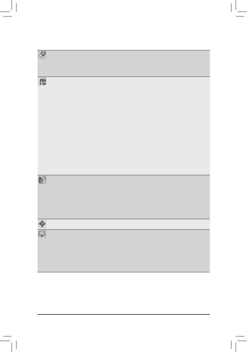
USB Chipset:
- 6 x USB 3.1 Gen 1 ports (4 ports on the back panel, 2 ports available through
the internal USB header)
- 6 x USB 2.0/1.1 ports (2 ports on the back panel, 4 ports available through
the internal USB headers)
Internal
Connectors
1 x 24-pin ATX main power connector
1 x 8-pin ATX 12V power connector
1 x CPU fan header
3 x system fan headers
1xRGBLEDstripheader
6 x SATA 6Gb/s connectors
2 x M.2 Socket 3 connectors
1 x front panel header
1 x front panel audio header
1 x S/PDIF Out header
1 x USB 3.1 Gen 1 header
2 x USB 2.0/1.1 headers
1 x Thunderbolt™ add-in card connector
1 x Trusted Platform Module (TPM) header (2x6 pin, for the GC-TPM2.0_S
module only)
1 x parallel port header
1 x serial port header
1 x Clear CMOS jumper
Back Panel
Connectors
1 x PS/2 keyboard/mouse port
1 x D-Sub port
1 x DVI-D port
1 x HDMI port
4 x USB 3.1 Gen 1 ports
2 x USB 2.0/1.1 ports
1xRJ-45port
6 x audio jacks
I/O Controller iTE® I/O Controller Chip
Hardware
Monitor
Voltage detection
Temperature detection
Fan speed detection
Overheating warning
Fan fail warning
Fan speed control
* Whether the fan speed control function is supported will depend on the cooler you
install.
- 7 -

The four memory sockets are divided into two channels and each channel has two memory sockets as following:
ChannelA:DDR4_2,DDR4_4
ChannelB:DDR4_1,DDR4_3
DualChannelMemoryCongurationsTable
DDR4_4 DDR4_2 DDR4_3 DDR4_1
2 Modules - - DS/SS - - DS/SS
DS/SS - - DS/SS - -
4 Modules DS/SS DS/SS DS/SS DS/SS
(SS=Single-Sided,DS=Double-Sided,"--"=NoMemory)
Due to CPU limitations, read the following guidelines before installing the memory in Dual Channel mode.
1. Dual Channel mode cannot be enabled if only one memory module is installed.
2. When enabling Dual Channel mode with two or four memory modules, it is recommended that memory
of the same capacity, brand, speed, and chips be used.
1-5 Installing an Expansion Card
Readthefollowingguidelinesbeforeyoubegintoinstallanexpansioncard:
•Make sure the motherboard supports the expansion card. Carefully read the manual that came
with your expansion card.
•Always turn off the computer and unplug the power cord from the power outlet before installing an
expansion card to prevent hardware damage.
1-6 Back Panel Connectors
USB 2.0/1.1 Port
TheUSBportsupportstheUSB2.0/1.1specication.UsethisportforUSBdevices.
PS/2 Keyboard/Mouse Port
Use this port to connect a PS/2 mouse or keyboard.
D-Sub Port
TheD-Subportsupportsa15-pinD-Subconnectorandsupportsamaximumresolutionof1920x1200@60Hz
(the actual resolutions supported depend on the monitor being used). Connect a monitor that supports
D-Sub connection to this port.
DVI-D Port (Note)
TheDVI-DportconformstotheDVI-Dspecicationandsupportsamaximumresolutionof1920x1200@60Hz
(the actual resolutions supported depend on the monitor being used). Connect a monitor that supports
DVI-D connection to this port.
(Note) The DVI-D port does not support D-Sub connection by adapter.
•Whenremovingthecableconnectedtoabackpanelconnector,rstremovethecablefromyour
device and then remove it from the motherboard.
•When removing the cable, pull it straight out from the connector. Do not rock it side to side to
prevent an electrical short inside the cable connector.
- 10 -

HDMI Port
The HDMI port supports HDCP 2.2 and Dolby TrueHD and DTS HD Master Audio
formats.Italsosupportsupto192KHz/16bit8-channelLPCMaudiooutput.You
can use this port to connect your HDMI-supported monitor. The maximum supported resolution is
4096x2160@30Hz,buttheactualresolutionssupportedaredependentonthemonitorbeingused.
USB 3.1 Gen 1 Port
TheUSB3.1Gen1portsupportstheUSB3.1Gen1specicationandiscompatibletotheUSB2.0
specication.UsethisportforUSBdevices.
RJ-45 LAN Port
The Gigabit Ethernet LAN port provides Internet connection at up to 1 Gbps data rate. The following
describes the states of the LAN port LEDs.
After installing the HDMI device, make sure to set the default sound playback device to HDMI.
(The item name may differ depending on your operating system.)
Center/Subwoofer Speaker Out (Orange)
Use this audio jack to connect center/subwoofer speakers.
Rear Speaker Out (Black)
Use this audio jack to connect rear speakers.
Side Speaker Out (Gray)
Use this audio jack to connect side speakers.
Line In (Blue)
The line in jack. Use this audio jack for line in devices such as an optical drive, walkman, etc.
Line Out/Front Speaker Out (Green)
The line out jack.
Mic In (Pink)
The line out jack.
Triple-DisplayCongurationsfortheOnboardGraphics:
Triple-displaycongurationsaresupportedafteryouinstallmotherboarddriversinOS.Onlydual-display
congurationsaresupportedduringtheBIOSSetuporPOSTprocess.
Activity LED
Connection/
Speed LED
LAN Port
Activity LED:
Connection/Speed LED:
State Description
Orange 1 Gbps data rate
Green 100 Mbps data rate
Off 10 Mbps data rate
State Description
Blinking Data transmission or receiving is occurring
Off No data transmission or receiving is occurring
- 11 -
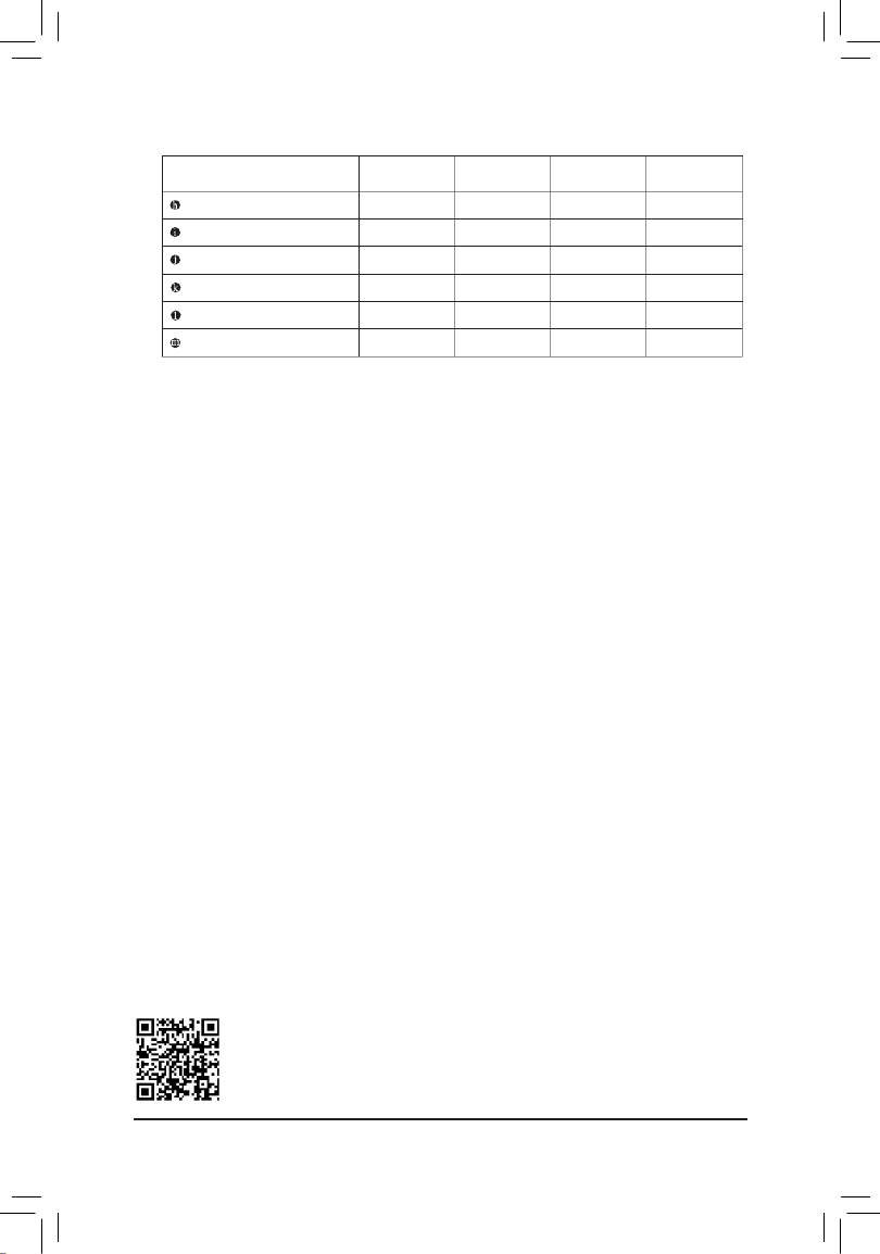
PleasevisitGIGABYTE'swebsitefordetailsonconguringtheaudiosoftware.
AudioJackCongurations:
Jack Headphone/
2-channel 4-channel 5.1-channel 7.1-channel
Center/Subwoofer Speaker Out a a
RearSpeakerOut aaa
Side Speaker Out a
Line In
Line Out/Front Speaker Out aaaa
Mic In
- 12 -
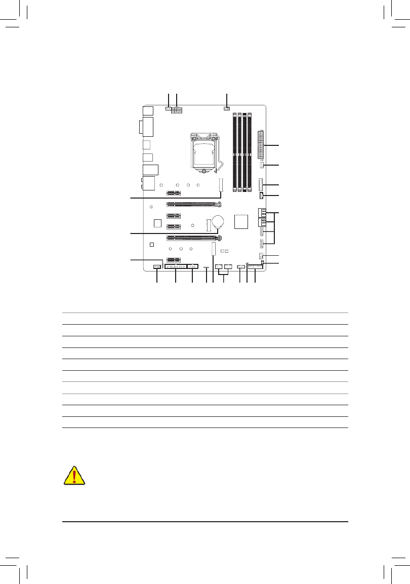
1-7 Internal Connectors
Readthefollowingguidelinesbeforeconnectingexternaldevices:
•First make sure your devices are compliant with the connectors you wish to connect.
•Before installing the devices, be sure to turn off the devices and your computer. Unplug the power
cord from the power outlet to prevent damage to the devices.
•After installing the device and before turning on the computer, make sure the device cable has
been securely attached to the connector on the motherboard.
1) ATX_12V_2X4
2) ATX
3) CPU_FAN
4) SYS_FAN1/2/3
5) LED_C
6) SATA3 0/1/2/3/4/5
7) M2M/M2P
8) F_PANEL
9) F_AUDIO
10) SPDIF_O
11) F_USB30
12) F_USB1/F_USB2
13) LPT
14) COM
15) TPM
16) THB_C
17) CLR_CMOS
18) BAT
19) CPU/DRAM/VGA/BOOT
817
4
2
6
11
16
59 13
14
14
4
19
18
10
7
12 157
3
- 13 -

3/4) CPU_FAN/SYS_FAN1/2/3 (Fan Headers)
All fan headers on this motherboard are 4-pin. Most fan headers possess a foolproof insertion design.
When connecting a fan cable, be sure to connect it in the correct orientation (the black connector wire is
the ground wire). The speed control function requires the use of a fan with fan speed control design. For
optimum heat dissipation, it is recommended that a system fan be installed inside the chassis.
•Be sure to connect fan cables to the fan headers to prevent your CPU and system from
overheating. Overheating may result in damage to the CPU or the system may hang.
•Thesefanheadersarenotcongurationjumperblocks.Donotplaceajumpercapontheheaders.
CPU_FAN/SYS_FAN1
1
SYS_FAN2/SYS_FAN3
1
Pin No. Denition
1 GND
2 Voltage Speed Control
3 Sense
4 PWM Speed Control
1/2) ATX_12V_2X4/ATX (2x4 12V Power Connector and 2x12 Main Power Connector)
With the use of the power connector, the power supply can supply enough stable power to all the components
onthemotherboard.Beforeconnectingthepowerconnector,rstmakesurethepowersupplyisturned
off and all devices are properly installed. The power connector possesses a foolproof design. Connect the
power supply cable to the power connector in the correct orientation.
The 12V power connector mainly supplies power to the CPU. If the 12V power connector is not connected,
the computer will not start.
To meet expansion requirements, it is recommended that a power supply that can withstand high
power consumption be used (500W or greater). If a power supply is used that does not provide the
required power, the result can lead to an unstable or unbootable system.
131
2412
ATX
ATX:
Pin No. Pin No.Denition Denition
1 3.3V 13 3.3V
2 3.3V 14 -12V
3 GND 15 GND
4 +5V 16 PS_ON (soft On/Off)
5 GND 17 GND
6 +5V 18 GND
7 GND 19 GND
8 Power Good 20 NC
9 5VSB (stand by +5V) 21 +5V
10 +12V 22 +5V
11 +12V (Only for 2x12-pin
ATX)
23 +5V (Only for 2x12-pin ATX)
12 3.3V (Only for 2x12-pin ATX) 24 GND (Only for 2x12-pin ATX)
ATX_12V_2X4:
Pin No. Pin No.Denition Denition
1 GND (Only for 2x4-pin 12V) 5 +12V (Only for 2x4-pin 12V)
2 GND (Only for 2x4-pin 12V) 6 +12V (Only for 2x4-pin 12V)
3 GND 7 +12V
4 GND 8 +12V
ATX_12V_2X4
41
85
- 14 -

10
12
9
11
2
2
1
1
13) LPT (Parallel Port Header)
The LPT header can provide one parallel port via an optional LPT port cable. For purchasing the optional
LPT port cable, please contact the local dealer.
Pin No. Pin No. Pin No.Denition Denition Denition
1STB- 10 GND 19 ACK-
2AFD- 11 PD4 20 GND
3PD0 12 GND 21 BUSY
4ERR- 13 PD5 22 GND
5PD1 14 GND 23 PE
6INIT- 15 PD6 24 No Pin
7PD2 16 GND 25 SLCT
8SLIN- 17 PD7 26 GND
9PD3 18 GND
1
226
25
14) COM (Serial Port Header)
The COM header can provide one serial port via an optional COM port cable. For purchasing the optional
COM port cable, please contact the local dealer.
Pin No. Pin No.Denition Denition
1 NDCD- 6 NDSR-
2 NSIN 7 NRTS-
3 NSOUT 8 NCTS-
4 9NDTR- NRI-
5 GND 10 No Pin
15) TPM (Trusted Platform Module Header)
You may connect a TPM (Trusted Platform Module) to this header.
Pin No. Pin No.Denition Denition
1LAD0 7LAD3
2VCC3 8GND
3LAD1 9LFRAME
4No Pin 10 NC
5LAD2 11 SERIRQ
6LCLK 12 LRESET
- 19 -

17) CLR_CMOS (Clear CMOS Jumper)
UsethisjumpertocleartheBIOScongurationandresettheCMOSvaluestofactorydefaults.Toclear
the CMOS values, use a metal object like a screwdriver to touch the two pins for a few seconds.
•Always turn off your computer and unplug the power cord from the power outlet before clearing
the CMOS values.
•Aftersystemrestart,gotoBIOSSetuptoloadfactorydefaults(selectLoadOptimizedDefaults)or
manuallyconguretheBIOSsettings(refertoChapter2,"BIOSSetup,"forBIOScongurations).
Open: Normal
Short: Clear CMOS Values
18) BAT (Battery)
Thebatteryprovidespowertokeepthevalues(suchasBIOScongurations,date,andtimeinformation)
intheCMOSwhenthecomputeristurnedoff.Replacethebatterywhenthebatteryvoltagedropstoalow
level, or the CMOS values may not be accurate or may be lost.
You may clear the CMOS values by removing the battery:
1. Turn off your computer and unplug the power cord.
2. Gently remove the battery from the battery holder and wait for one minute. (Or use a metal
object like a screwdriver to touch the positive and negative terminals of the battery holder,
making them short for 5 seconds.)
3. Replacethebattery.
4. Plug in the power cord and restart your computer.
•Always turn off your computer and unplug the power cord before replacing the battery.
•Replacethebatterywithanequivalentone.Damagetoyourdevicesmayoccurifthebatteryis
replaced with an incorrect model.
•Contact the place of purchase or local dealer if you are not able to replace the battery by yourself
or uncertain about the battery model.
•When installing the battery, note the orientation of the positive side (+) and the negative side (-)
of the battery (the positive side should face up).
•Used batteries must be handled in accordance with local environmental regulations.
16) THB_C (Thunderbolt™ Add-in Card Connector)
This connector is for a GIGABYTE Thunderbolt™ add-in card.
Supports a Thunderbolt™ add-in card.
1
19) CPU/DRAM/VGA/BOOT (Status LEDs)
The status LEDs show whether the CPU, memory, graphics card, and operating system are working
properlyaftersystempower-on.IftheCPU/DRAM/VGALEDison,thatmeansthecorrespondingdevice
is not working normally; if the BOOT LED is on, that means you haven't entered the operating system yet.
CPU:CPU status LED
DRAM:Memory status LED
VGA:Graphics card status LED
BOOT:Operating system status LED
CPU DRAM
VGA BOOT
- 20 -

&Uncore Ratio
Allows you to set the CPU Uncore ratio. The adjustable range is dependent on the CPU being used.
&Uncore Frequency
Displays the current CPU Uncore frequency.
&CPU Flex Ratio Override
EnablesordisablestheCPUFlexRatio.ThemaximumCPUclockratiowillbebasedontheCPU Flex
Ratio Settings CPU Clock Ratio Auto value if is set to . (Default: Disabled)
&CPU Flex Ratio Settings
AllowsyoutosettheCPUFlexRatio.TheadjustablerangemayvarybyCPU.
&Intel(R) Turbo Boost Technology (Note)
Allows you to determine whether to enable the Intel® CPU Turbo Boost technology. lets the BIOS Auto
automaticallycongurethissetting.(Default:Auto)
&Turbo Ratio (Note)
Allows you to set the CPU Turbo ratios for different number of active cores. sets the CPU Turbo ratios Auto
accordingtotheCPUspecications.(Default:Auto)
&No. of CPU Cores Enabled (Note)
Allows you to select the number of CPU cores to enable in an Intel® multi-core CPU (the number of CPU
cores may vary by CPU). AutoletstheBIOSautomaticallycongurethissetting.(Default:Auto)
&Hyper-Threading Technology (Note)
Allows you to determine whether to enable multi-threading technology when using an Intel® CPU that
supports this function. This feature only works for operating systems that support multi-processor mode.
AutoletstheBIOSautomaticallycongurethissetting.(Default:Auto)
&Intel(R) Speed Shift Technology (Intel® Speed Shift Technology) (Note)
Enables or disables Intel® Speed Shift Technology. Enabling this feature allows the processor to ramp up
its operating frequency more quickly and then improves the system responsiveness. (Default: Auto)
&CPU Enhanced Halt (C1E) (Note)
Enables or disables Intel
®
CPU Enhanced Halt (C1E) function, a CPU power-saving function in system halt
state.
When enabled, the CPU core frequency and voltage will be reduced during system halt state to
decrease power consumption. AutoletstheBIOSautomaticallycongurethissetting.(Default:Auto)
&C3 State Support (Note)
Allows you to determine whether to let the CPU enter C3 mode in system halt state. When enabled, the
CPU core frequency and voltage will be reduced during system halt state to decrease power consumption.
The C3 state is a more enhanced power-saving state than C1. AutoletstheBIOSautomaticallycongure
this setting. (Default: Auto)
&C6/C7 State Support (Note)
Allows you to determine whether to let the CPU enter C6/C7 mode in system halt state. When enabled, the
CPU core frequency and voltage will be reduced during system halt state to decrease power consumption.
The C6/C7 state is a more enhanced power-saving state than C3. AutoletstheBIOSautomaticallycongure
this setting. (Default: Auto)
&C8 State Support (Note)
Allows you to determine whether to let the CPU enter C8 mode in system halt state. When enabled, the CPU
core frequency and voltage will be reduced during system halt state to decrease power consumption. The
C8 state is a more enhanced power-saving state than C6/C7. AutoletstheBIOSautomaticallycongure
this setting. (Default: Auto)
(Note) This item is present only when you install a CPU that supports this feature. For more information about
Intel® CPUs' unique features, please visit Intel's website.
- 24 -

&Fan Speed Control
Allows you to determine whether to enable the fan speed control function and adjust the fan speed.
Normal Allows the fan to run at different speeds according to the temperature. You can adjust
the fan speed with System Information Viewer based on your system requirements.
(Default)
Silent Allows the fan to run at slow speeds.
Manual Allows you to control the fan speed in the curve graph.
Full Speed Allows the fan to run at full speeds.
&Fan Control Use Temperature Input
Allows you to select the reference temperature for fan speed control.
&Temperature Interval
Allows you to select the temperature interval for fan speed change.
&Fan Control mode
Auto Lets the BIOS automatically detect the type of fan installed and sets the optimal control
mode. (Default)
Voltage Voltage mode is recommended for a 3-pin fan.
PWM PWM mode is recommended for a 4-pin fan.
&Fan Stop
Enables or disables the fan stop function. You can set the temperature limit using the temperature curve.
The fan stops operation when the temperature is lower than the limit. (Default: Disabled)
&Temperature
Displays the current temperature of the selected target area.
&Fan Speed
Displays current fan speeds.
&Temperature Warning Control
Sets the warning threshold for temperature. When temperature exceeds the threshold, BIOS will emit
warning sound. Options are: Disabled (default), 60oC/140oF, 70oC/158oF, 80oC/176oF, 90oC/194oF.
&Fan Fail Warning
Allows the system to emit warning sound if the fan is not connected or fails. Check the fan condition or fan
connection when this occurs. (Default: Disabled)
- 28 -
Product specificaties
| Merk: | Gigabyte |
| Categorie: | Moederbord |
| Model: | B365 HD3 |
| Breedte: | 305 mm |
| Diepte: | 225 mm |
| Grafische adapter: | HD Graphics |
| Ethernet LAN: | Ja |
| Maximum resolutie: | 4096 x 2160 Pixels |
| Meegeleverde kabels: | SATA |
| Aantal USB 2.0-poorten: | 2 |
| VGA (D-Sub)poort(en): | 1 |
| Aantal HDMI-poorten: | 1 |
| Aantal Ethernet LAN (RJ-45)-poorten: | 1 |
| HDCP: | Ja |
| HDMI versie: | 1.4 |
| DVI-D poorten: | 1 |
| Meegeleverde software: | Norton Internet Security (OEM)\nRealtek 8118 Gaming LAN bandwidth Control |
| Ondersteunt Windows: | Windows 10 Education x64, Windows 10 Enterprise x64, Windows 10 Home x64, Windows 10 Pro x64, Windows 10 x64 |
| Aantal poorten USB 3.2 Gen 1 (3.1 Gen 1) Type A: | 4 |
| Processor socket: | LGA 1151 (Socket H4) |
| Processorfabrikant: | Intel |
| Maximum intern geheugen: | 64 GB |
| Audio-uitgangskanalen: | 7.1 kanalen |
| Snelle installatiehandleiding: | Ja |
| ECC: | Ja |
| Ethernet interface type: | Gigabit Ethernet |
| Chipset moederbord: | Intel B365 |
| Geheugen slots type: | DIMM |
| Audiochip: | Realtek ALC887 |
| Meegeleverde drivers: | Ja |
| Grafische adapter-familie: | Intel |
| Geheugen kanaal: | Dubbelkanaals |
| PCI Express x16 (Gen 3.x) slots: | 2 |
| PCI Express x1 (Gen 3.x) slots: | 4 |
| Intel® Optane™ Memory Ready: | Ja |
| Aantal displays ondersteund: | 3 |
| Ondersteunde opslagstationinterfaces: | SATA III |
| PS/2 poort(en): | 1 |
| Component voor: | PC |
| Soorten RAID: | 0, 1,5, 10 |
| Maximum geheugen grafische adapter: | 1024 MB |
| Aantal SATA III connectors: | 6 |
| Non-ECC: | Ja |
| Compatibele processors: | Intel Celeron, Intel Core i3, Intel Core i5, Intel Core i7, Intel Core i9, Intel Itanium |
| Ondersteunde geheugen types: | DDR4-SDRAM |
| Max. aantal SMP-processoren: | 1 |
| Wifi: | Nee |
| Ondersteunde types opslag-drives: | HDD & SSD |
| Moederbord chipset familie: | Intel |
| Moederbord form factor: | ATX |
| Aantal geheugenslots: | 4 |
| Supported memory clock speeds: | 2133,2400,2666 MHz |
| BIOS type: | UEFI AMI |
| Grootte BIOS-geheugen: | 128 Mbit |
| ACPI version: | 5.0 |
| Systeem Management BIOS (SMBIOS) versie: | 2.7 |
| Ondersteuning voor parallel processing: | 2-Way CrossFireX, Quad-GPU CrossFireX |
| Aansluiting voor CPU koeler: | Ja |
| Aansluitingen voor behuizingsventilatoren: | 3 |
| ATX Power connector (24-pin): | Ja |
| Voorpaneel-connector: | Ja |
| USB 2.0 aansluitingen: | 2 |
| Aansluiting voor audiopaneel aan voorzijde: | Ja |
| PC gezondheids monitor: | FAN, Temperature, Voltage |
| Niet gebufferd geheugen: | Ja |
| USB 3.2 Gen 1 (3.1 Gen 1)-aansluitingen: | 1 |
| TPM connector: | Ja |
| Aantal Parallel ATA aansluitingen: | 1 |
| Clear CMOS jumper: | Ja |
| Intel® Extreme Memory Profile (XMP): | Ja |
| Aantal M.2 (M) slots: | 2 |
| 12V vermogen-connector: | Ja |
| Serial port headers: | 1 |
| DualBIOS: | Ja |
| Versie Desktop Management Interface (DMI): | 2.7 |
Heb je hulp nodig?
Als je hulp nodig hebt met Gigabyte B365 HD3 stel dan hieronder een vraag en andere gebruikers zullen je antwoorden
Handleiding Moederbord Gigabyte

10 Maart 2025
11 Februari 2025
11 Februari 2025
11 Februari 2025
11 Februari 2025
11 Februari 2025
11 Februari 2025
11 Februari 2025
11 Februari 2025
11 Februari 2025
Handleiding Moederbord
- Moederbord Asus
- Moederbord Asrock
- Moederbord EPoX
- Moederbord Evga
- Moederbord MSI
- Moederbord Sharkoon
- Moederbord NZXT
- Moederbord Intel
- Moederbord Supermicro
- Moederbord ECS
- Moederbord Foxconn
- Moederbord Advantech
- Moederbord Elitegroup
- Moederbord Biostar
Nieuwste handleidingen voor Moederbord

8 April 2025
8 April 2025
3 April 2025
3 April 2025
3 April 2025
3 April 2025
2 April 2025
2 April 2025

29 Maart 2025
27 Maart 2025