Gigabyte 8S648FXP-RZ Handleiding
Gigabyte
Moederbord
8S648FXP-RZ
Lees hieronder de 📖 handleiding in het Nederlandse voor Gigabyte 8S648FXP-RZ (40 pagina's) in de categorie Moederbord. Deze handleiding was nuttig voor 26 personen en werd door 2 gebruikers gemiddeld met 4.5 sterren beoordeeld
Pagina 1/40

8S648FXP-RZ /
8S648FXP-RZ-C
User's Manual
Intel® Pentium® 4 Processor Motherboard
Rev. 1001
12ME-S648FXPRZ-1001
Copyright
© 2004 GIGABYTE TECHNOLOGY CO., LTD
Copyright by GIGA-BYTE TECHNOLOGY CO., LTD. ("GBT"). No part of this manual may be reproduced or transmitted in any from
without the expressed, written permission of GBT.
Trademarks
Third-party brands and names are the property of their respective owners.
Notice
Please do not remove any labels on motherboard, this may void the warranty of this motherboard.
Due to rapid change in technology, some of the specifications might be out of date before publication of this booklet.
The author assumes no responsibility for any errors or omissions that may appear in this document nor does the author make a
commitment to update the information contained herein.

Motherboard
8S648FXP-RZ
Nov. 3, 2004
Mother Board
8S648FXP-RZ
Nov. 3, 2004
Preparing Your Computer
Computer motherboards and expansion cards contain very delicate Integrated Circuit (IC) chips. To
protect them against damage from static electricity, you should follow some precautions whenever you
work on your computer.
1. Unplug your computer when working on the inside.
2. Use a grounded wrist strap before handling computer components. If you do not have one,
touch both of your hands to a safely grounded object or to a metal object, such as the power
supply case.
3. Hold components by the edges and try not touch the IC chips, leads or connectors, or other
components.
4. Place components on a grounded antistatic pad or on the bag that came with the components
whenever the components are separated from the system.
5. Ensure that the ATX power supply is switched off before you plug in or remove the ATX power
connector on the motherboard.
Installing the motherboard to the chassis
If the motherboard has mounting holes, but they don't line up with the holes on the base and there
are no slots to attach the spacers, do not become alarmed you can still attach the spacers to the
mounting holes. Just cut the bottom portion of the spacers (the spacer may be a little hard to cut off, so
be careful of your hands). In this way you can still attach the motherboard to the base without worrying
about short circuits. Sometimes you may need to use the plastic springs to isolate the screw from the
motherboard PCB surface, because the circuit wire may be near by the hole. Be careful, don't let the
screw contact any printed circuit write or parts on the PCB that are near the fixing hole, otherwise it
may damage the board or cause board malfunctioning.

- 4 -8S648FXP-RZ Series Motherboard
English
Table of Contents
Chapter 1 Introduction ................................................................................................... 5
Features Summary .................................................................................................................. 5
8S648FXP-RZ Series Motherboard Layout ............................................................................... 6
Block Diagram ......................................................................................................................... 7
Hardware Installation Process .................................................................................................. 8
Step 1: Install the Central Processing Unit (CPU) .................................................................... 8
Step 1-1: CPU Installation ....................................................................................................... 9
Step 1-2: CPU Cooling Fan Installation ................................................................................. 9
Step 2: Install Memory Modules ............................................................................................. 10
Step 3: Install AGP Card ......................................................................................................... 11
Step 4: Install I/O Peripherals Cables ...................................................................................... 11
Step 4-1: I/O Back Panel Introduction ................................................................................... 11
Step 4-2: Connectors Introduction ........................................................................................ 12
Chapter 2 BIOS Setup ................................................................................................. 19
The Main Menu (For example: BIOS Ver. : E10) ................................................................... 19
Standard CMOS Features ..................................................................................................... 21
Advanced BIOS Features ...................................................................................................... 23
Integrated Peripherals ............................................................................................................. 25
Power Management Setup ..................................................................................................... 27
PnP/PCI Configurations ......................................................................................................... 29
PC Health Status ................................................................................................................... 30
MB Intelligent Tweaker(M.I.T.) ................................................................................................ 31
Top Performance .................................................................................................................... 32
Load Fail-Safe Defaults ........................................................................................................... 33
Load Optimized Defaults ......................................................................................................... 33
Set Supervisor/User Password ............................................................................................. 34
Save & Exit Setup ................................................................................................................. 35
Exit Without Saving ................................................................................................................ 35
Chapter 3 Install Drivers .............................................................................................. 37

Introduction
English
- 5 -
Chapter 1 Introduction
Features Summary
Motherboard y8S648FXP-RZ or 8S648FXP-RZ-C
CPU ySocket 478 for Intel® Pentium® 4 (Northwood, Prescott) with HT Technology
yIntel® Pentium® 4 800/533/400MHz FSB
y2nd cache depends on CPU
Chipset yNorthbridge : SiS 648FX
ySouthbridge : SiS 964
Memory y3 184-pin DDR DIMM sockets, supports up to 3GB DRAM (Max)
ySupports DDR400/DDR333/DDR266 DIMM
ySupports up to 2 unbuffered DIMM DDR400
ySupports up to 3 unbuffered DIMM DDR333
ySupports only 2.5V DDR SDRAM
Slots y1 AGP slot supports 8X/4X(1.5V) mode
y5 PCI slots
IDE Connections y2 IDE connections (Ultra DMA33/ATA66/ATA100/ATA133),
allows connection of 4 IDE devices
FDD Connections y1 FDD connection, allows connection of 2 FDD devices
Onboard SATA y2 Serial ATA ports from SiS 964 (SATA0, SATA1)
Peripherals y1 Parallel port supporting Normal/EPP/ECP mode
y2 Serial port (COMA, COMB)
y8 USB 2.0/1.1 ports (rear x 4, front x 4 via cable)
y1 front audio connector
y1 PS/2 keyboard port
y1 PS/2 mouse port
Onboard LAN* yOnboard ICS1883 chipset (10/100Mbit)*
y1 RJ45 port*
Onboard Audio yALC655 codec
ySupports 2/ 4/ 6 channel audio
yLine Out/ Line In/ Mic In connection
ySPDIF In/ Out
yCD In connector
I/O Control yIT8705
Hardware Monitor ySystem voltage detection
yCPU temperature detection
yCPU / System fan speed detection
Onboard SATA RAID yOnboard SiS 964 chipset (SATA0, SATA1)
ySupports data striping (RAID 0) or mirroring (RAID 1) function
ySupports data transfer rate of up 150MB
ySupports a maximum of 2 SATA connections
BIOS yUse of licensed AWARD BIOS
ySupports Q-Flash
Additional Features ySupports @BIOS
ySupports EasyTune
Form Factor yATX form factor, 21cm x 29.5cm
"*" Only for 8S648FXP-RZ.

- 6 -8S648FXP-RZ Series Motherboard
English
"*" Only for 8S648FXP-RZ.
"#" Only for 8S648FXP-RZ-C.
8S648FXP-RZ Series Motherboard Layout
KB_MS
COMA
LPT
USB
LAN *
SOCKET478
CPU_FAN
ATX
COMB
IDE2
ATX_12V
8S648FXP-RZ Hyper Threading
Support
SPDIF_IO
PWR_LED
F_USB2
F_PANEL
SYS _FAN
F_USB1
F_AUDIO
IDE1
DDR1
SiS 648FX
IT8705
P4 Titan
FDD
PCI3
BIOS
SiS 964
PCI4
PCI5
BAT
PCI2
CODEC
CLR_CMOS
CD_IN
AGP
DDR2
PCI1
DDR3
SUR_CEN
ICS1883 *
#
AGP 8X
VRM10.0
29.5 cm
21 cm
R_USB
MIC_IN
LINE_IN
LINE_OUT
SATA1
SATA0
-C
IR
Introduction
English
- 7 -
"*" Only for 8S648FXP-RZ.
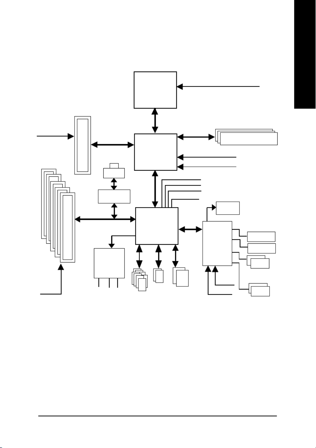
Block Diagram
Pentium 4
Socket 478
CPU
SiS 648FX
AC97
CODEC
SiS 964
CPUCLK+/- (100/133/200 MHz)
System Bus
400/533/800 MHz
DDR
266/333/400 MHz
ZCLK (66/133MHz)
HCLK+/- (100/133MHz)
66/133 MHz
33 MHz
14.318 MHz
48 MHz
24 MHz
33 MHz
LPC BUS
AGP 4X/8X
AGPCLK
(66MHz)
5 PCI
PCICLK
(33MHz)
AC97 Link
MIC
LINE-IN
LINE-OUT
8 USB
Ports
ATA33/66/
100/133
IDE Channels
Floppy
LPT Port
PS/2
KB/Mouse
2 COM Ports
BIOS
IT8705
ICS1883 *
RJ45 *
2 SATA
Ports

- 8 -8S648FXP-RZ Series Motherboard
English
To set up your computer, you must complete the following steps:
Step 1- Install the Central Processing Unit (CPU)
Step 2- Install memory modules
Step 3- Install expansion cards
Step 4- Install I/O Peripherals Cables
Hardware Installation Process
Step 1: Install the Central Processing Unit (CPU)
Before installing the processor, adhere to the following warning:
1. Please make sure the CPU type is supported by the motherboard.
2. The processor will overheat without the heatsink and/or fan, resulting in permanent
irreparable damage.
3. If you do not match the CPU socket Pin 1 and CPU cut edge well, it will cause improper
installation. Please change the insert orientation.
4. Apply thermal grease between the processor and cooling fan.
5. Never run the processor without the heatsink properly and firmly attached. Permanent
damage will result.
6. Please set the CPU host frequency in accordance with your processor's specifications.
We don't recommend you to set the system bus frequency over the CPU's specification
because these specific bus frequencies are not the standard specifications for CPU,
chipset and most of the peripherals. Whether your system can run under these specific
bus frequencies properly will depend on your hardware configurations, including CPU,
Memory, Cards…etc.
HT functionality requirement content :
Enabling the functionality of Hyper-Threading Technology for your computer system
requires all of the following platform components:
- CPU: An Intel® Pentium 4 Processor with HT Technology
- Chipset: A SiS®
Chipset that supports HT Technology
- BIOS: A BIOS that supports HT Technology and has it enabled
- OS: An operation system that has optimizations for HT Technology
Step 2
Step 4
Step 4
Step 4
Step 1
Step 3

- 9 - Hardware Installation Process
English
Step 1-1: CPU Installation
Figure 1.
Pull the rod to the 90-degree directly.
Figure 2.
Locate Pin 1 in the socket and look for a (golden) cut edge on the
CPU upper corner. Insert the CPU into the socket. (Do not force the
CPU into the socket.) Then move the socket lever to the locked
position while holding pressure on the center of the CPU.
Step 1-2: CPU Cooling Fan Installation
Figure 1.
Apply the thermal tape(or grease) to provide better heat conduction
between your CPU and cooling fan.
Figure 2.
Fasten the cooling fan supporting-base onto the CPU socket on the
motherboard.
Socket
Actuation
Lever
Figure 3.
Make sure the CPU fan is plugged to the CPU fan connector, than
install complete.
- 10 -8S648FXP-RZ Series Motherboard
English
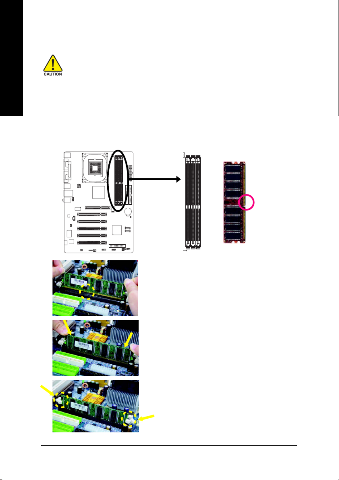
Step 2: Install Memory Modules
DDR
Notch
Before installing the memory modules, please comply with the following conditions:
1. Please make sure that the memory used is supported by the motherboard. It is
recommended that memory of similar capacity, specifications and brand be used.
2. Before installing or removing memory modules, please make sure that the computer
power is switched off to prevent hardware damage.
3. Memory modules have a foolproof insertion design. A memory module can be installed
in only one direction. If you are unable to insert the module, please switch the direction.
The motherboard supports DDR memory modules, whereby BIOS will automatically detect memory
capacity and specifications. Memory modules are designed so that they can be inserted only in one
direction. The memory capacity used can differ with each slot.
1. The DIMM socket has a notch, so the DIMM memory
module can only fit in one direction.
2. Insert the DIMM memory module vertically into the DIMM
socket. Then push it down.
3. Close the plastic clip at both edges of the DIMM sockets
to lock the DIMM module.
Reverse the installation steps when you wish to
remove the DIMM module.

- 12 -8S648FXP-RZ Series Motherboard
English
Step 4-2: Connectors Introduction
LAN port *
The provided Internet connection is fast Ethernet, providing data transfer speeds of 10/100Mbps.
Line In jack
Devices like CD-ROM, walkman etc. can be connected to Line In jack.
Line Out jack
Connect the stereo speakers or earphone to this connector.
MIC In jack
Microphone can be connect to MIC In jack.
2
31
8144
12
6
17
16
5
11
13
9
10
7
15
1) ATX_12V
2) ATX
3) CPU_FAN
4) SYS_FAN
5) FDD
6) IDE1 / IDE2
7) SATA0 / SATA1
8) PWR_LED
9) F_PANEL
10) F_AUDIO
11) SPDIF_IO
12) SUR_CEN
13) CD_IN
14) F_USB1 / F_USB2
15) IR
16) CLR_CMOS
17) BAT
"*" Only for 8S648FXP-RZ.

- 13 - Hardware Installation Process
English
1/2) ATX_12V / ATX (Power Connector)
With the use of the power connector, the power supply can supply enough stable power to all the
components on the motherboard. Before connecting the power connector, please make sure that
all components and devices are properly installed. Align the power connector with its proper
location on the motherboard and connect tightly. The ATX_12V power connector mainly supplies
power to the CPU. If the ATX_12V power connector is not connected, the system will not start.
Caution! Please use a power supply that is able to handle the system voltage requirements. It is
recommended that a power supply that can withstand high power consumption be used (300W or
greater). If a power supply is used that does not provide the required power, the result can lead
to an unstable system or a system that is unable to start.
3/4) CPU_FAN / SYS_FAN (Cooler Fan Power Connector)
The cooler fan power connector supplies a +12V power voltage via a 3-pin power connector and
possesses a foolproof connection design. Most coolers are designed with color-coded power
connector wires. A red power connector wire indicates a positive connection and requires a +12V
power voltage. The black connector wire is the ground wire (GND).
Caution!
Please remember to connect the power to the CPU fan to prevent CPU overheating and failure.
Pin No. Definition
1 GND
2 +12V
3 Sense
1
1
CPU_FAN
SYS_FAN
Pin No. Definition
1 GND
2 GND
3 +12V
4 +12V
Pin No. Definition
1 3.3V
2 3.3V
3 GND
4 VCC
5 GND
6 VCC
7 GND
8 Power Good
95V SB (stand by +5V)
10 +12V
Pin No. Definition
11 3.3V
12 -12V
13 GND
14 PS_ON(soft on/off)
15 GND
16 GND
17 GND
18 -5V
19 VCC
20 VCC
1
2010
11
1 2
3 4

- 14 -8S648FXP-RZ Series Motherboard
English
6) IDE1 / IDE2 (IDE1 / IDE2 Connector)
An IDE device connects to the computer via an IDE connector. One IDE connector can connect to
one IDE cable, and the single IDE cable can then connect to two IDE devices (hard drive or optical
drive). If you wish to connect two IDE devices, please set the jumper on one IDE device as Master
and the other as Slave (for information on settings, please refer to the instructions located on the IDE
device).
IDE1IDE2
1
39
2
40
5) FDD (FDD Connector)
The FDD connector is used to connect the FDD cable while the other end of the cable connects to
the FDD drive. The types of FDD drives supported are: 360KB, 720KB, 1.2MB, 1.44MB and
2.88MB. Please connect the red power connector wire to the pin1 position.
33
34
1
2
7) SATA0 / SATA1 (Serial ATA Connector)
Serial ATA can provide 150MB/s transfer rate. Please refer to the BIOS setting for the Serial ATA and
install the proper driver in order to work properly.
Pin No. Definition
1 GND
2 TXP
3 TXN
4 GND
5 RXN
6 RXP
7 GND
71
SATA1
71
SATA0
For more detailed Serial ATA RAID setup information, please
visit our website at http:\\www.gigabyte.com.tw.
Product specificaties
| Merk: | Gigabyte |
| Categorie: | Moederbord |
| Model: | 8S648FXP-RZ |
| Breedte: | 295 mm |
| Diepte: | 209 mm |
| Type stroombron: | ATX |
| Aantal USB 2.0-poorten: | 2 |
| Microfoon, line-in ingang: | Ja |
| Aantal Ethernet LAN (RJ-45)-poorten: | 1 |
| Hoofdtelefoonuitgangen: | 1 |
| Audio-uitgang: | Realtek ALC655 CODEC |
| Meegeleverde software: | Norton Internet Security \n- Norton Anti-Virus \n- Norton Personal Firewall \n- Norton Privacy Control \n- Norton Parental Control \n- Norton Spam Alert \nGIGABYTE Windows Utility Manager \nAdobe Acrobat Reader\n |
| Processor socket: | Socket 478 |
| Processorfabrikant: | Intel |
| Maximum intern geheugen: | 3 GB |
| Netwerkfuncties: | ICS1883 LAN |
| Seriële poort(en): | 2 |
| Uitbreidingsslots: | 1 x AGP 8x/4x \n5 x PCI (PCI 2.2)\n |
| Parallelle poort(en): | 1 |
| Moederbord form factor: | ATX |
| Aantal geheugenslots: | 3 |
| Aantal SATA-aansluitingen: | 2 |
| USB 2.0 aansluitingen: | 2 |
| Aansluiting voor diskettestation: | Ja |
| S/PDIF uitgang: | Ja |
| CD/AUX audio-ingang: | Ja |
| Aantal Parallel ATA aansluitingen: | 2 |
| GAME/MIDI aansluiting: | Ja |
Heb je hulp nodig?
Als je hulp nodig hebt met Gigabyte 8S648FXP-RZ stel dan hieronder een vraag en andere gebruikers zullen je antwoorden
Handleiding Moederbord Gigabyte

10 Maart 2025
11 Februari 2025
11 Februari 2025
11 Februari 2025
11 Februari 2025
11 Februari 2025
11 Februari 2025
11 Februari 2025
11 Februari 2025
11 Februari 2025
Handleiding Moederbord
- Moederbord Asus
- Moederbord Asrock
- Moederbord EPoX
- Moederbord Evga
- Moederbord MSI
- Moederbord Sharkoon
- Moederbord NZXT
- Moederbord Intel
- Moederbord Supermicro
- Moederbord ECS
- Moederbord Foxconn
- Moederbord Advantech
- Moederbord Elitegroup
- Moederbord Biostar
Nieuwste handleidingen voor Moederbord

8 April 2025
8 April 2025
3 April 2025
3 April 2025
3 April 2025
3 April 2025
2 April 2025
2 April 2025

29 Maart 2025
27 Maart 2025