Extron TLP Pro 1225MG Handleiding
Lees hieronder de 📖 handleiding in het Nederlandse voor Extron TLP Pro 1225MG (6 pagina's) in de categorie Monitor. Deze handleiding was nuttig voor 15 personen en werd door 2 gebruikers gemiddeld met 4.5 sterren beoordeeld
Pagina 1/6

1
IMPORTANT:
Go to for the
complete user guide and installation
instructions before connecting the
product to the power source.
www.extron.com
TLP Pro 1225MG, 1525MG, and 1725MG • Setup Guide
Overview
The Extron® TLP Pro 1225MG, TLP Pro 1525MG, and TLP Pro 1725MG are wall-mounted touchpanels with capacitive, edge-to-edge
glass touchscreens. The TLP Pro 1225MG has a 12.1 inch screen with a 1280x800 resolution. The TLP Pro 1525MG has a 15.6 inch
screen with a 1366x768 resolution. The TLP Pro 1725MG has a 17.3 inch screen with a 1920x1080 resolution. All three touchpanels
are ideal for any AV applications requiring large touchpanels with exible mounting options and fully customizable interfaces. This
guide provides instructions for experienced installers to mount and install these touchpanels. For more complete details, see the
TLPPro 1225, 1525, and 1725 Series User Guide at www.extron.com.
Setup Checklist
Get Ready
Download and install the latest version of the following software:
GUI Designer — Used to design layouts for Extron TouchLink® Pro touchpanels and third party touch interfaces.
Global Configurator® Plus and Professional — Used to set up and congure the control processor and touchpanel.
Global Scripter® — Used to rovide an integrated development environment for Extron control systems programming.
Global Scripter provides an Extron-exclusive Python™ library (ControlScript®) and modules to get you started.
Toolbelt — Used for device discovery, device information, rmware updates, and conguration of network settings, system
utilities, and user management for TouchLink Pro devices.
NOTE: All four software programs are available from www.extron.com.
Obtain the following network information from your network administrator:
DHCP status (on or off). If DHCP is off, you also require:
IP address Subnet mask Gateway
Username — This can be either or .
Passwords — The factory congured passwords for all accounts on this device have been set to the device serial number.
Passwords can be changed during conguration. Passwords are case sensitive.
NOTE: If the device is reset to default settings, the passwords are reset to the default password, which is (for
either or ).
Make a note of the touchpanel MAC address from the label on the back of the device.
Mount and Cable All Devices
ATTENTION:
• Do not power on the touchpanels until you have read the Attention in the “Power Supply” section of the
TLPPro 1225, 1525, and 1725 Series User Guide.
• Ne branchez pas les écrans tactiles avant d’avoir lu la mise en garde dans la section «sources d’alimentation» du TLPPro
1225, 1525, and 1725 Series User Guide.
Mount the units. There are several mounting options for TouchLink Pro touchpanels (see on page 2). Mounting
Connect cables to the touchpanels (see on page 4).Rear Panel Features
Connect the touchpanel to a Power over Ethernet (PoE) injector. The TLP Pro 1725MG ships with the PI 140 power injector.
A power injector must be purchased separately for the 12-inch and 15-inch models.
Connect an Extron IP Link® Pro control processor to the same Ethernet subnetwork as the touchpanel.
Set up the Touchpanels for Network Communication
Connect the PC that you will use for setup, the control processor, and touchpanel .to the same Ethernet subnetwork
Use the (see page 6) or Toolbelt (see Setup Menu Toolbelt Help File) to set the DHCP status and, if necessary, the IP
address, subnet mask, gateway, and related settings for the touchpanel.
Configure the Touchpanels
Create a graphical user interface with GUI Designer (see for step-by-step instructions).GUI Designer Help File
Associate functions with the graphical user interface features by conguring (see the ) or Global Configurator Help File
programming (see the ) the system.Global Scripter Help File

2
TLP Pro 1225MG, 1525MG, and 1725MG • Setup Guide
Mounting
ATTENTION:
• Do not install the TLP Pro 1225MG, TLP Pro 1525MG, or TLP Pro 1725MG in a re resistant rated wall or partition
assembly.
• Ne pas installer le TLP Pro 1225MG, le TLP Pro 1525MG, ou le TLP Pro 1725MG dans un mur résistant au feu ou une
cloison.
• All structural steps and electrical installation must be performed by qualied personnel in accordance with local and
national building codes and electrical codes.
• Toute étape structurelle et installation électrique, doit être effectuée par un personnel qualié, conformément aux codes du
bâtiment, aux codes incendie et sécurité, et aux codes électriques, locaux et nationaux.
Wall Mounting
The touchpanels can be wall mounted using the provided hardware. Where local codes require a rear metal enclosure, either model
can be mounted using the Extron BB 700M (not provided). Figure 1 shows the TLP Pro 1525MG. Mount the TLP Pro 1225MG or
TLP Pro 1725MG in the same way.
With a wall box
Some local building codes require the touchpanel to be mounted in a wall box such as the Extron BB 700M. This installation
procedure is described below.
1. Cut a hole in the drywall, 9.6 inches (243 mm) wide
x 6.6 inches (166 mm) high, and install the
Install the BB 700M (optional).
TLP Pro 1525MG
Back View
Hold the touchpanel at a slight angle
Mount the touchpanel over the two
hooks on the mounting plate.
Add the mounting plate. Align with
the wall box and mark holes for screws.
Secure the mounting plate
to the wall with screws (4).
Place the provided mounting sc ws (2)re
with washers in the mounting sc w slotre
in the touchpanel.
6
5
3
1
2
4
7
Secu the touchpanel by tightening there
mounting sc ws against the base of the re
mounting plate.
BB 700M (see gure 1, 1), as described
in the (see BB 700M Installation Guide
www.extron.com).
2. Place the metal mounting plate
against the wall, mark the four
mounting holes, and drill four pilot
holes (2) in those locations.
3. Secure the mounting plate with four
#10 screws (3).
4. Run and connect cables to the back
of the touchpanel (4, and see Rear
Panel Features on page 4).
5. Insert the two provided Phillips pan
head #6-32 x ¾ inch length screws
with washers in the mounting screw
slot (5, see gure 1, Back View
inset). Leave a gap for the ange at the
bottom of the mounting plate to t into.
6. Hold the touchpanel at a slight angle
and lower the notches at the top of
the back panel over the hooks of the
mounting plate (6).
7. Swing the bottom of the touchpanel
inwards so that it lies at against the
mounting plate with the ange at the bottom
of the mounting plate sitting in a groove in the
bottom of the touchpanel.
8. Secure the touchpanel to the mounting plate with the
mounting screws (7).
Without a wall box
If the wall box is not required by local building codes, you can
mount the touchpanel directly into drywall.
1. Download the cut-out template for your touchpanel from Figure 1. TLP Pro 1525MG Mounting
www.extron.com. Print it at 100% (no scaling).
2. Use the template to mark the wall, cut the hole, and drill the four pilot holes. The size of the cut-out hole is 9.25 inches (235 mm)
wide x 6.25 inches (159 mm) high.
3. Secure the mounting plate and complete the installation, as described in steps 3 through 8 above.
3
Product Category
Rack Mounting
These touchpanels can be mounted in any standard 19-inch equipment rack, using the optional rack mounting kit. The
TLP Pro 1225MG can be mounted with the RM2 mounting kit. The TLP Pro 1525MG and the TLP Pro 1725MG can be mounted in
the RM3 mounting kit. Read the “Underwriters Labs Guidelines for Rack Mounting” section of the TLPPro 1225, 1525, and 1725
Series User Guide and follow the instructions provided with the appropriate kit.
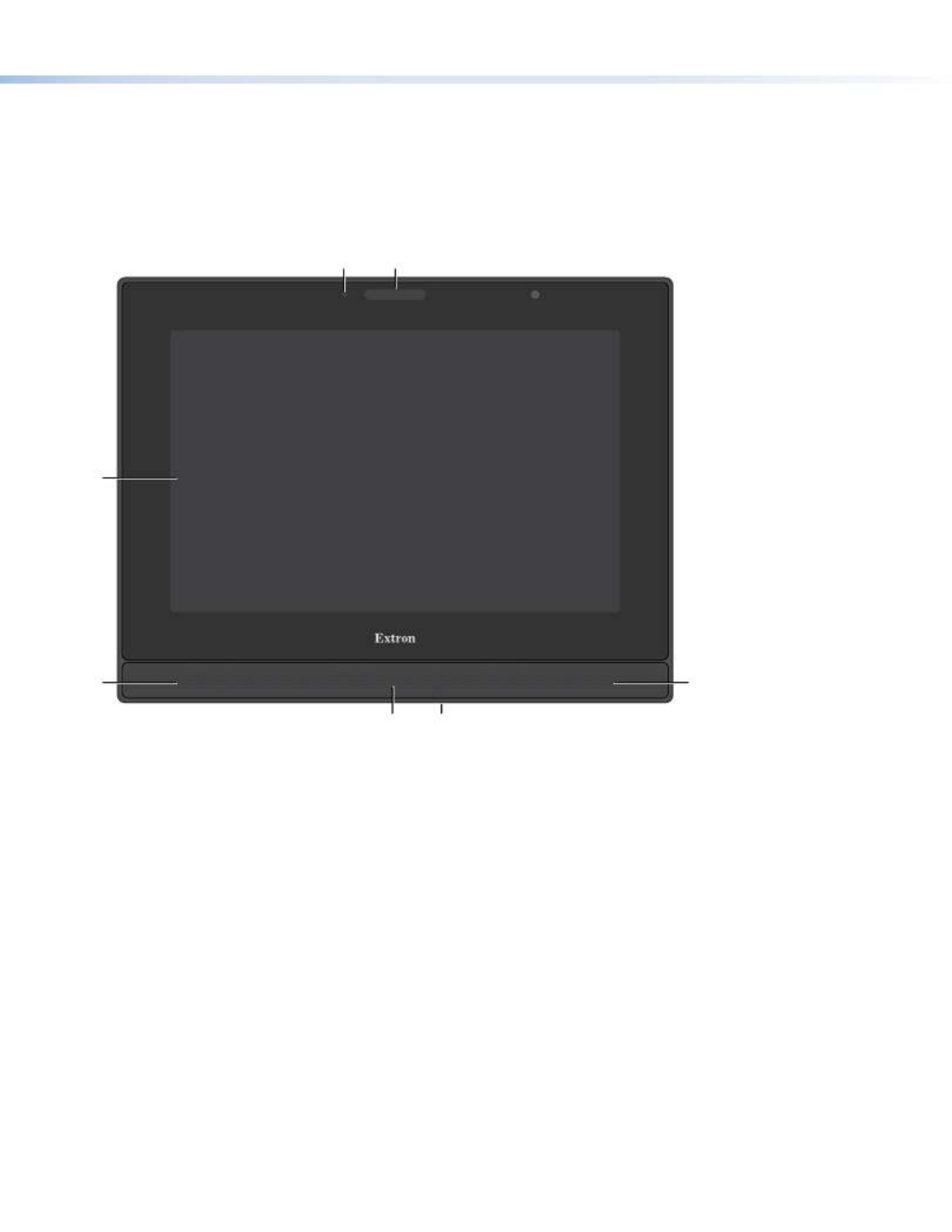
Front Panel Features
Figure 2 shows the TLP Pro 1225MG front panel. The TLP Pro 1525MG and TLP Pro 1725MG features are very similar.
A B
C
D D
E F
Figure 2. TLP Pro 1225MG Front Panel
A — Monitors ambient light level and adjusts screen brightness.Ambient light sensor
B — Can be programmed to provide system feedback. This LED light bar is located above the screen.Status light
C — Provides simple control of AV systems.Capacitive touch screen
zThe TLP Pro 1225MG has a 12.1 inch screen with a 1280x800 resolution.
zThe TLP Pro 1525MG has a 15.6 inch screen with a 1366x768 resolution.
zThe TLP Pro 1725MG has a 17.3 inch screen with a 1920x1080 resolution.
D — Provide stereo audio for video preview and audible feedback from button presses. They are located below the Speakers
screen, one on each side of the panel.
E — Detects motion between three to ve feet from the touchpanel, and at least 15° from the center axis.Motion sensor
zIf the sleep timer feature has been set, and no motion has been detected for a user-dened period of time, the touchpanel
enters sleep mode.
zIf the wake on motion feature has been set, and motion is detected by the sensor while the screen is in sleep mode, the
screen display is restored and active.
For more information about setting the Sleep Timer Wake on Motion or , see the “Setup Menu” section of the TLPPro 1225,
1525, and 1725 Series User Guide.
F — Activates the setup menu (see ). Access the button from under the touchpanel. It performs the Menu button Setup Menu
same function as the rear panel Menu button but is easier to reach when the touchpanel is installed.
Product specificaties
| Merk: | Extron |
| Categorie: | Monitor |
| Model: | TLP Pro 1225MG |
Heb je hulp nodig?
Als je hulp nodig hebt met Extron TLP Pro 1225MG stel dan hieronder een vraag en andere gebruikers zullen je antwoorden
Handleiding Monitor Extron

2 April 2025
18 September 2024
5 September 2024
5 September 2024
5 September 2024
5 September 2024
5 September 2024
5 September 2024
5 September 2024
5 September 2024
Handleiding Monitor
- Monitor Bosch
- Monitor Philips
- Monitor HP
- Monitor Sony
- Monitor Samsung
- Monitor Xiaomi
- Monitor Panasonic
- Monitor Epson
- Monitor LG
- Monitor Huawei
- Monitor Asus
- Monitor Canon
- Monitor Daewoo
- Monitor Garmin
- Monitor Honeywell
- Monitor JVC
- Monitor JBL
- Monitor Medion
- Monitor Olympus
- Monitor Pioneer
- Monitor Toshiba
- Monitor Xerox
- Monitor Yamaha
- Monitor Yealink
- Monitor Abus
- Monitor Acer
- Monitor Acti
- Monitor Ag Neovo
- Monitor Alesis
- Monitor Alienware
- Monitor Alpine
- Monitor AOC
- Monitor AOpen
- Monitor Apc
- Monitor Apple
- Monitor Archos
- Monitor Asrock
- Monitor Barco
- Monitor Behringer
- Monitor Belinea
- Monitor BenQ
- Monitor Blaupunkt
- Monitor BlueBuilt
- Monitor Boss
- Monitor Brandson
- Monitor Danfoss
- Monitor Dell
- Monitor Denver
- Monitor Eizo
- Monitor Emachines
- Monitor EverFocus
- Monitor Faytech
- Monitor Focal
- Monitor Fujitsu
- Monitor Ganz
- Monitor GeoVision
- Monitor Gigabyte
- Monitor GlobalTronics
- Monitor Godox
- Monitor Haier
- Monitor Hannspree
- Monitor Hercules
- Monitor Hikvision
- Monitor Hisense
- Monitor Hitachi
- Monitor HKC
- Monitor Hyundai
- Monitor Ibm
- Monitor IHealth
- Monitor Iiyama
- Monitor InFocus
- Monitor Insignia
- Monitor Interlogix
- Monitor Kogan
- Monitor Konig
- Monitor LaCie
- Monitor Legamaster
- Monitor Lenovo
- Monitor LightZone
- Monitor M-Audio
- Monitor Mackie
- Monitor Mad Catz
- Monitor Marquant
- Monitor Marshall
- Monitor Maxdata
- Monitor Maxell
- Monitor Midas
- Monitor Mirai
- Monitor Mitsubishi
- Monitor Monacor
- Monitor MSI
- Monitor Nec
- Monitor Newstar
- Monitor Packard Bell
- Monitor Peaq
- Monitor Peerless
- Monitor Plantronics
- Monitor Prestigio
- Monitor Provision ISR
- Monitor Pyle
- Monitor Razer
- Monitor RCF
- Monitor Renkforce
- Monitor Ricoh
- Monitor Ring
- Monitor Salora
- Monitor Samson
- Monitor Sanyo
- Monitor Schneider
- Monitor Sharp
- Monitor Silvercrest
- Monitor Simrad
- Monitor Skytronic
- Monitor Smart
- Monitor Soundstream
- Monitor Sunny
- Monitor Sunstech
- Monitor Tannoy
- Monitor TCL
- Monitor Terra
- Monitor Tesla
- Monitor Thomson
- Monitor Triton
- Monitor Velleman
- Monitor Viessmann
- Monitor Viewsonic
- Monitor Vitek
- Monitor Vivitek
- Monitor Waeco
- Monitor Westinghouse
- Monitor Wyse - Dell
- Monitor Xoro
- Monitor Zalman
- Monitor Jay-tech
- Monitor Jensen
- Monitor Joy-it
- Monitor Jung
- Monitor Odys
- Monitor Omron
- Monitor ONYX
- Monitor Optoma
- Monitor Orion
- Monitor 3M
- Monitor Continental Edison
- Monitor Caliber
- Monitor CSL
- Monitor Monoprice
- Monitor Shure
- Monitor Voxicon
- Monitor EMOS
- Monitor Festo
- Monitor Newline
- Monitor Atlona
- Monitor Hamlet
- Monitor Cooler Master
- Monitor NZXT
- Monitor Thermaltake
- Monitor Citizen
- Monitor Kubo
- Monitor Eurolite
- Monitor Corsair
- Monitor Deltaco
- Monitor KeepOut
- Monitor Ozone
- Monitor Tripp Lite
- Monitor Chauvet
- Monitor Approx
- Monitor Cisco
- Monitor KTC
- Monitor ARRI
- Monitor Bauhn
- Monitor LC-Power
- Monitor HyperX
- Monitor Atomos
- Monitor Yorkville
- Monitor Jupiter
- Monitor Adam
- Monitor Genelec
- Monitor AORUS
- Monitor Avocor
- Monitor DoubleSight
- Monitor Planar
- Monitor SEIKI
- Monitor EC Line
- Monitor MicroTouch
- Monitor HoverCam
- Monitor ELO
- Monitor IFM
- Monitor DataVideo
- Monitor Kindermann
- Monitor ART
- Monitor Da-Lite
- Monitor Allen & Heath
- Monitor ProXtend
- Monitor AJA
- Monitor Adj
- Monitor Ikan
- Monitor Element
- Monitor Dahua Technology
- Monitor Neumann
- Monitor Peerless-AV
- Monitor PreSonus
- Monitor IK Multimedia
- Monitor Swissonic
- Monitor QSC
- Monitor ESI
- Monitor Marshall Electronics
- Monitor RGBlink
- Monitor POSline
- Monitor Dynaudio
- Monitor Krom
- Monitor Vorago
- Monitor Promethean
- Monitor Fostex
- Monitor Prowise
- Monitor Neets
- Monitor AMX
- Monitor Stairville
- Monitor Crestron
- Monitor I3-Technologies
- Monitor CTOUCH
- Monitor SMART Technologies
- Monitor BOOX
- Monitor SPL
- Monitor Aputure
- Monitor Drawmer
- Monitor Blue Sky
- Monitor Advantech
- Monitor Iadea
- Monitor Sonifex
- Monitor Kali Audio
- Monitor Kramer
- Monitor Avantone Pro
- Monitor AVer
- Monitor ITek
- Monitor Posiflex
- Monitor Vimar
- Monitor Speco Technologies
- Monitor Akuvox
- Monitor Antelope Audio
- Monitor X-Rite
- Monitor EKO
- Monitor IBoardTouch
- Monitor PeakTech
- Monitor Elite Screens
- Monitor Hollyland
- Monitor Mitsai
- Monitor V7
- Monitor Palmer
- Monitor TV One
- Monitor Christie
- Monitor Hanwha
- Monitor Phoenix Contact
- Monitor COMMBOX
- Monitor Yiynova
- Monitor Pelco
- Monitor Lilliput
- Monitor KRK
- Monitor Ernitec
- Monitor Planet Audio
- Monitor Datacolor
- Monitor Fluid
- Monitor Postium
- Monitor HELGI
- Monitor Desview
- Monitor Syscom
- Monitor Allsee
- Monitor Alogic
- Monitor Night Owl
- Monitor ProDVX
- Monitor Varad
- Monitor PureTools
- Monitor CTL
- Monitor Game Factor
- Monitor Nixeus
- Monitor Chimei
- Monitor Blue Sea
- Monitor AMCV
- Monitor SWIT
- Monitor TVLogic
- Monitor Feelworld
- Monitor GeChic
- Monitor Oecolux
- Monitor ADS-TEC
- Monitor Satco
- Monitor SideTrak
- Monitor TRIUMPH BOARD
- Monitor Casalux
- Monitor Positivo
- Monitor Transvideo
- Monitor Innocn
- Monitor Shimbol
- Monitor Raysgem
- Monitor Motrona
- Monitor Ikegami
- Monitor Wohler
- Monitor Elvid
- Monitor Portkeys
- Monitor Neat
- Monitor Mimo Monitors
- Monitor Gamber-Johnson
- Monitor Enttec
- Monitor American Dynamics
- Monitor AIS
- Monitor Eve Audio
- Monitor Wortmann AG
- Monitor Viotek
- Monitor Vidi-Touch
- Monitor CoolerMaster
- Monitor Mobile Pixels
- Monitor Atlantis Land
- Monitor HEDD
- Monitor Colormetrics
- Monitor Monkey Banana
- Monitor SmallHD
- Monitor IStarUSA
- Monitor Qian
- Monitor UPERFECT
- Monitor Freedom Scientific
- Monitor OSEE
- Monitor GVision
- Monitor Mybeo
- Monitor Bearware
- Monitor IOIO
- Monitor DTEN
- Monitor Cocopar
- Monitor Titan Army
- Monitor BookIT
- Monitor Wimaxit
- Monitor Delvcam
- Monitor Xenarc
- Monitor Japannext
Nieuwste handleidingen voor Monitor

8 April 2025

8 April 2025

7 April 2025
7 April 2025

4 April 2025

4 April 2025
1 April 2025
30 Maart 2025
30 Maart 2025
30 Maart 2025