Dedicated Micros DM/CAM/BC5/A Handleiding
Dedicated Micros
Bewakingscamera
DM/CAM/BC5/A
Lees hieronder de 📖 handleiding in het Nederlandse voor Dedicated Micros DM/CAM/BC5/A (36 pagina's) in de categorie Bewakingscamera. Deze handleiding was nuttig voor 34 personen en werd door 2 gebruikers gemiddeld met 4.5 sterren beoordeeld
Pagina 1/36

540TV Lines
Super High Resolution Color Camera
1/3'' INTERLINE TRANSFER CCD
HIGH RESOLUTION
DAY/LOW LIGHT
Please read this manual thoroughly before use, and keep it handy for future reference.
INSTRUCTION MANUAL
Model No.: DM/CAM/BC5/A

LIMITATION OF LIABILITY
THE INFORMATION IN THIS PUBLICATION IS BELIEVED TO BE ACCURATE IN
ALL RESPECTS, HOWEVER, WE CANNOT ASSUME RESPONSIBILITY FOR ANY
CONSEQUENCES RESULTING FROM THE USE THEREOF. THE INFORMATION
CONTAINED HEREIN IS SUBJECT TO CHANGE WITHOUT NOTICE. REVISIONS
OR NEW EDITIONS TO THIS PUBLICATION MAY BE ISSUED TO INCORPORATE
SUCH CHANGES.
ISSUE 1 - APRIL 2006
ii

WARNINGS AND CAUTIONS:
CAUTION:
CAUTION
CAUTION
CAUTION
CAUTION
CAUTION
RISK OF ELECTRIC SHOCK
DO NOT OPEN
CAUTION: TO REDUCE THE RISK OF ELECTRIC SHOCK,
DO NOT REMOVE COVER(OR BACK).
NO USER-SERVICEABLE PARTS INSIDE.
REFER SERVICING TO QUALIFIED SERVICE PERSONNEL.
EXPLANATION OF GRAPHICAL SYMBOLS
The lightning flash with arrowhead symbol, within an equilateral triangle, is
intended to alert the user to the presence of uninsulated "dangerous voltage"
within the product's enclosure that may be of sufficient magnitude to constitute a
risk of electric shock to persons.
The exclamation point within an equilateral triangle is intended to alert the user to
the presence of important operating and maintenance (servicing) instructions in the
literature accompanying the product.
Should any liquid or solid object fall into the cabinet,
unplug the unit and have it checked by the qualified
personnel before operating it any further.
Unplug the unit from the wall oulet if it is not going to
be used for several days or more. To disconnect the
cord, pull it out by the plug. Never pull the cord itself.
Allow adequate air circulation to prevent internal heat
build-up. Do not place the unit on surfaces (rugs,
blankets, etc.) or near materials(curtains, draperies)
that may block the ventilation holes.
Height and vertical linearity controls located at the
rear panel are for special adjustments by qualified
personnel only.
Do not install the unit in an extremely hot or
humid place or in a place subject to excessive
dust, mechanical vibration.
The unit is not designed to be waterproof.
Exposure to rain or water may damage the unit.
Clean the unit with a slightly damp soft cloth.
Use a mild household detergent. Never use
strong solvents such as thinner or benzine as
they might damage the finish of the unit.
Retain the original carton and packing
materials for safe transport of this unit in the
future.
Safety ----------------------------------------- Installation -----------------------------------
Cleaning --------------------------------------
PRECAUTIONS
TO REDUCE THE RISK OF FIRE OR ELECTRIC SHOCK, DO NOT EXPOSE THIS PRODUCT TO RAIN OR
MOISTURE. DO NOT INSERT ANY METALLIC OBJECTS THROUGH THE VENTILATION GRILLS OR
OTHER OPENINGS ON THE EQUIPMENT.
iii

FCC INFORMATION : THIS EQUIPMENT HAS BEEN TESTED
AND FOUND TO COMPLY WITH THE LIMITS FOR A CLASS A DIGITAL
DEVICE, PURSUANT TO PART 15 OF THE FCC RULES. THESE
LIMITS ARE DESIGNED TO PROVIDE REASONABLE PROTECTION
AGAINST HARMFUL INTERFERENCE WHEN THE EQUIPMENT IS
OPERATED IN A COMMERCIAL ENVIRONMENT. THIS EQUIPMENT
GENERATES, USES, AND CAN RADIATE RADIO FREQUENCY
ENERGY AND IF NOT INSTALLED AND USED IN ACCORDANCE WITH
THE INSTRUCTION MANUAL, MAY CAUSE HARMFUL INTERFERENCE
TO RADIO COMMUNICATIONS. OPERATION OF THIS EQUIPMENT IN
A RESIDENTIAL AREA IS LIKELY TO CAUSE HARMFUL
INTERFERENCE IN WHICH CASE THE USER WILL BE REQUIRED TO
CORRECT THE INTERFERENCE AT HIS OWN EXPENSE.
CAUTION : CHANGES OR MODIFICATIONS NOT EXPRESSLY
APPROVED BY THE PARTY RESPONSIBLE FOR COMPLIANCE
COULD VOID THE USER'S AUTHORITY TO OPERATE THE EQUIPMENT.
THIS CLASS A DIGITAL APPARATUS COMPLIES WITH CANADIAN
ICES-003.
NORME NMB-003 DU CANADA.
WARNING
This is a Class A product. In a domestic environment this product
may cause radio interference in which case the user may be required
measures.
to take adequate
CE COMPLIANCE STATEMENT
FCC COMPLIANCE STATEMENT
iv

vi
THIS PAGE INTENTIONALLY LEFT BLANK.

INTRODUCTION 1
CAMERA OVERVIEW 2
FUNCTION DESCRIPTION 3
OPERATING CAMERA 4
CONNECTIONS 20
CONTENTS OF PACKAGE 21
MANUAL IRIS LENS ADJUSTMENT 21
VIDEO AUTO IRIS INSTALLATION & ADJUSTMENT 22
DC AUTO IRIS LENS INSTALLATION & ADJUSTMENT 23
BACK FOCUS ADJUSTMENT 25
ZOOM LENS BACK FOCUS ADJUSTMENT 26
TROUBLESHOOTING AND MAINTENANCE 27
SPECIFICATIONS 28
TABLE OF CONTENTS
vii

The camera provides high-quality images using SONY CCD technology
especially designed for closed-circuit television (CCTV) and security
surveillance applications.
Features:
High resolution and high performance 1/3" SONY Super HAD CCD
technology
Excellent picture quality
540 lines(Color) of resolution
0.3 Lux(Color) @ F1.2 Sensitivity
C/CS, backfocus cam for easy adjustment
Auto electronic shutter [1/60(1/50) ~ 1/120,000] and manual electronic
shutter modes
OSD (On Screen Display)
Auto and manual white balance modes
BLC (Back Light Compensation)
Day&Night (Auto / Color / B/W)
Privacy Zone 4point
AGC (Auto Gain Control)
Sens-up (x2 ~ x128)
MIRROR
VIDEO OUT(BNC)
Motion Detection 4point
Internal / AC line lock
Compatible with
with 4-pin connector
Operates in 12VDC or 24VAC
Use Certified / Listed Class 2 power supply only.
video- or DC-type lenses with OSD select
Quick connect for video or DC lens
INTRODUCTION
- 1 -
IMPORTANT : The user of this camera is responsible for
checking and complying with local, state, and federal laws
and statutes concerning the recording and monitoring of
audio signals.
- 2 -
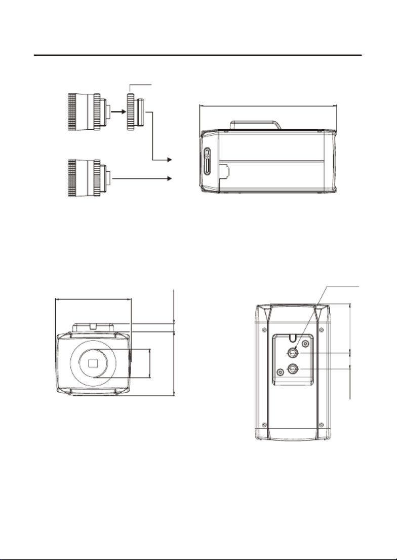
CAMERA OVERVIEW
C Mount Ring
(C MOUNT LENS)
(CS MOUNT LENS)
SIDE VIEW
1-32UNEF
56.0mm
66.0mm
120.0mm
14.0mm 43.0mm
1/4-20UNC
7.0mm
FRONT VIEW TOP VIEW

- 3 -
FUNCTION DESCRIPTION
- SIDE VIEW
- REAR VIEW
1
2
3
4
5
6
7
8
Left Button
Up Button
Enter Button
Right Button
Down Button
Power Indicator
AC/DC Compatible Input Terminal
Video Out Connector
1
2
Focus Adjusting Fixing Screw
Auto Iris Lens Connector
12
2
1
5
7
3
4
6
8

- 4 -
OPERATING CAMERA
<MAIN MENU>
WB
AE
BLC
CAM SET
SPECIAL
D&N
DNR
MOTION DET OFF
END
<SETTINGS>
Settings can be made using the 5 buttons located on the back of the camera.
1) The MAIN MENU is displayed on the monitor when press the ENTER
button.
2) Please select any function you wish to activate by using the UP and
DOWN buttons.
The arrow can be moved up or down by using the UP and DOWN
buttons. Please position the arrow to point to the function you wish to
operate
<MAIN MENU>
WB
AE
BLC
CAM SET
SPECIAL
D&N
DNR
MOTION DET OFF
END
Select any function
you wish to operate
by using the
UP and DOWN buttons.
If appears at the mode
you wish to operate,
it means that there is a
sub menu which can be
selected by pressing the
ENTER button.
Modes can be changed
using the LEFT or RIGHT
buttons.

- 5 -
3) Press the LEFT or RIGHT button if you wish to change mode.
When the LEFT or RIGHT button is pressed, available values and
modes are displayed in order. Please keep pressing the button until
you get to the mode you wish to operate.
4) To finishing the setting without save, select 'END' and then press the
ENTER button. But if you want to keep the setting, enter the CAM SET
menu, select 'SAVE' and then press the ENTER button.
NOTE : If ' - - -' appears at the mode item, it means that is no mode
available to be selected.
<WB>
Press the MENU button to access the "WB" mode.
WHITE BAL.
MODEL ATW / AWC / MANUAL
R GAIN 1 ~ 70
B GAIN 1 ~ 70
EXIT
1) MODE
- AWC (Auto White Balance Control)
Please press the MENU button while the camera is directed at a piece
of white paper to obtain the optimum state under current illumination. If
the environment including the light source is changed, you have to
adjust the white balance again.
- ATW (Auto Tracking White Balance)
O
This mode can be used within the color temperature range 1,800 K ~
O
10,500 K

- 6 -
- MANUAL
The manual adjustment mode enables finer adjustment. You can adjust
the RED and BLUE color values while monitoring the color changes on
the object at the 'R GAIN' or 'B GAIN' menu. The 'R GAIN' and 'B GAIN'
is available only at the MANUAL mode.
NOTE : Under the following conditions the WHITE BALANCE function
may not operate properly. In such cases, please select the AWC mode.
- When the object's surroundings have a very high color temperature.
(eg. A clear sky and sunset)
- When the object's surroundings are dark
- If the camera directly faces a fluorescent light or is installed in a place
where there are considerable changes in illumination, the WHITE
BALANCE function may become unstable.
2) R GAIN
Adjust the R GAIN by using the LEFT or RIGHT button.
(This is effective only in case of selecting the MANUAL MODE) 0 ~ 100
3) B GAIN
Adjust the B GAIN by using the LEFT or RIGHT button.
(This is effective only in case of selecting the MANUAL MODE) 0 ~ 100
4) END
RETURN to MAIN MENU.

- 8 -
1) MODE
- AUTO
Auto control of the shutter speed can be achieved. When AUTO mode is
on, the speed is controlled automatically according to the brightness of
the screen.
BRIGHTNESS Adjust the "BRIGHTNESS" to the desired LEVEL
by using LEFT or RIGHT button.
END RETURN to AE MENU
- SHUTTER
The shutter speed can be controlled manually.
X128 ~ 1/120,000
- FLK
Please select 'FLK' mode when flickering occurs on the screen, due to
an imbalance between illumination and frequency.
NTSC Model : 1/100, PAL Model : 1/120
NOTE :
- When selecting DC/VIDEO lens, you can choose 'FLK' or '1/60 or 1/50'.
The 'FLK' functions FLICKLESS OFF and the '1/60 or 1/50' functions E/I
OFF.
- While using the internal system, if the shutter setting is on 'AUTO' and
the camera is directly facing a bright fluorescent light, the image on the
screen can be adversely affected. Therefore please choose the
installation location with care.
- When 'SHUTTER' mode is on, the SENS UP function does not operate.
2) AGC (Auto Gain Control)
Adjust the AGC GAIN to the desired mode by using LEFT or RIGHT
button. As the level of gain increases, the screen gets brighter and the
level of noise also increases.
- HIGH / MIDDLE / LOW / OFF
BRIGHTNESS Adjust the "BRIGHTNESS" to the desired LEVEL
by using LEFT or RIGHT button.
1 ~ 70
END RETURN to AE MENU

- 9 -
3) LENS
Automatic control of the brightness level through the intensity of radiation.
- MANUAL
Available by using manual lens.
- DC
LEVEL Adjust the brightness level by pressing the LEFT or
RIGHT button at the DC's submenu. Level setting
is available only by using the DC IRIS lens.
Then put the A/I LENS selection switch on the side
of the camera in the "DC" position.
END RETURN to the AE MENU
- VIDEO
NOTE :
- When using an auto iris lens, the setting of the auto iris lens selection
switch, located on the back of the camera, must be on DC or VIDEO
depending on the type of the lens which is being used.
- The brightness of the screen can be adjusted in DC mode. The
brightness can be adjusted within the range of 0~70. The optimum level
of brightness for the user can be achieved by adjustment.
When using Auto Iris Lens with Video type
1) Adjust ALC volume on the lens properly. Normally ALC volume
should be turned all the way to Av(Average).
2) According to the type of the lens used, the lens may not perform
properly. In such a case, adjust the volume level on the lens.
3) For adjusting the Volume Level, enter the submenu at the 'VIDEO
LENS' mode. And then adjust it to the desired state.
NOTES
When the auto iris is mounted, you have to set the DC/Video selection
switch on the side of the camera properly according to status of this
selection switch.

- 10 -
4) SENS-UP (Low illuminance)
SENS UP helps maintain a bright, clear screen image by automatically
detecting changes in the level of light in low light level conditions.
- OFF
The function does not operate.
- AUTO
Low light level auto mode.
X2 ~ X128
NOTE :
- When SHUTTER is in the manual mode, SENS UP does not operate.
- When AGC is turned off. SENS UP does not operate.
NOTE :
- The maximum storage magnification in low light level movement
situations can be adjusted by pressing the ENTER button in 'AUTO'
mode. (x2 ~ x128)
- As the magnification increase, the screen gets brighter; however the
after image also increases.
- If storage magnification is increased while SENS UP is operating, it may
cause noise, and spots may appear; however this is normal.
5) END
RETURN to the MAIN MENU.

- 11 -
<BLC>
Press the MENU button to access the "BLC" mode.
BLC
LEVEL HIGH / MIDDLE / LOW / OFF
END
1) LEVEL
HIGH / MIDDLE / LOW / OFF
2) END
RETURN to MAIN MENU.
Prevents such a back light effect to secure a clear image under all illumination
environments.

<CAM SET>
Press the MENU button to access the "CAM SET" mode.
CAM SET
TITLE
1) TITLE
Select the camera TITLE that may be composed of letters, numbers,
special texts, or a combination of these up to 15 digits.
- Move to left
- Move to right
- Erase all characterCLR
- Change the position of the titlePOS
(If you want to change the position of the title, press
ENTER button at the POS. Find the position you wish to
display the title by using the 4 directional buttons, and then
press the ENTER button.)
- EndEND
NOTE :
- If the wrong name has been input....
If you press the ENTER button after moving the cursor the CLR, all the
letters will be erased. If you want to correct a letter, please move the
cursor to the arrow at the bottom left of the screen and press 'ENTER'.
Please position the cursor above the letter you wish to correct, and then
move the cursor onto the letter you wish to choose and press the ENTER
button.
DISPLAY ON / OFF
DEFAULT
SAVE
END
- 12 -
2) DISPLAY
ON : Display TITLE in the monitor.
OFF : Disappear TITLE in the monitor.
3) DEFAULTS
The factory setting of the Camera is selected.
4) SAVE
The changed Baud Rate is saved.
5) END
RETURN to MAIN MENU.
<SPECIAL>
Press the MENU button to access the "SPECIAL" mode.
SPECIAL
SHARPNESS
-OFF
SYC
-INT
0 ~ 359PHASE
END
PRIVACY
-OFF
-ON
AREA SEL
AREA STATE
-ON
0 ~ 31LEVEL
END
MIRROR OFF / ON
-L / L
AREA1 / AREA2 / AREA3 / AREA4
OFF / ON
AREA TONE 1 ~ 100
TOP 1 ~ 62
DOWN 1 ~ 62
LEFT 1 ~ 96
RIGHT 1 ~ 96
END
END
- 13 -

1) SHARPNESS
The outline of the video image becomes cleaner and more distinctive as
the level of SHARPNESS increases. If the level goes up excessively,
however, it may affect the video image and generate noise.
- LEVEL
Adjust the SHARPNESS of the screen by using the LEFT or RIGHT
button.
0 ~ 31
- END
RETURN to SPECIAL MENU
2) MIRROR
ON: Sets a horizontal image inversion.
OFF: Cancels the inversion.
3) SYNC
Two SYNCHRONIZATION modes are available INTERNAL and
EXTERNAL LINE-LOCK. In LINE-LOCK mode, it synchronizes the video
signal between cameras without a synchronous generator. The line-lock
synchronization is only used in the areas of 60Hz(NTSC Models) /
50Hz(PAL Models)
- INT
This mode is necessary for using the internal synchronization.
- L/L
This mode is necessary for the operation of multi cameras because it
synchronizes the camera phase by using the external signal(AC Signal).
LEVEL Sync phase is adjustable in line lock mode
0 ~ 359
END RETURN to SPECIAL MENU
NOTE :
- When the power frequency is 50Hz, you can not use line-lock mode
(NTSC Models).
- When the power frequency is 60Hz, you can not use line-lock mode
(PAL models).
- 'Sync' mode is fixed to 'INT' in DC 12V input power.
- 14 -

4) PRIVACY
Conceals the areas you do not wish to appear on the screen.
OFF : Cancels the PRIVACY mode.
Operates the PRIVACY mode. To adjust PRIVACY MASK, press ON :
'ENTER' button.
- AREA SEL
Select the AREA you want to adjust.
- AREA STATE
Select 'ON' to display the selected AREA, and select 'OFF' to conceal
the selected AREA.
- AREA TONE
Adjust the tone of the selected AREA.
1 ~ 100
- TOP
Adjust the TOP of the selected AREA by using the LEFT or RIGHT
button.
- DOWN
Adjust the DOWN of the selected AREA by using the LEFT or RIGHT
button.
- LEFT
Adjust the LEFT of the selected AREA by using the LEFT or RIGHT
button.
- RIGHT
Adjust the RIGHT of the selected AREA by using the LEFT or RIGHT
button.
- END
RETURN to SPECIAL MENU.
5) END
RETURN to MAIN MENU
- 15 -

<D&N>
Press the MENU button to access the "D&N" mode.
D&N
1) D&N
- AUTO
This camera has a function which automatically changes to the
appropriate mode for daytime or night-time. The COLOR mode is
operated for daytime, and it converts to BW mode for night-time.
- COLOR
In this mode, the camera outputs the video image only in color.
- BW
In this mode, the camera outputs the video image only in black and
white.
2) END
RETURN to MAIN MENU.
NOTE :
- When the AGC is turned off. AUTO does not operate.
- When an infrared light is used, there may be a problem with focusing.
MODE AUTO / COLOR / BW
END
- 16 -

<DNR>
Press the MENU button to access the "DNR" mode.
DNR
The background noise in the low light level decreases automatically as the
level of gain changes.
1) LEVEL
- OFF
There is no reduction in noise level.
- LOW
There is a small reduction in noise level with almost no ghost image.
- MIDDLE
The most effective mode. There is a sufficient reduction in noise levels
without causing much ghost imaging.
- HIGH
The level of noise is reduced greatly, however there is an increase in
ghost imaging.
2) END
RETURN to MAIN MENU.
NOTE :
- When AGC is turned off. DNR does not operate.
LEVEL HIGH / MIDDLE / LOW / OFF
END
- 17 -

<MOTION DET>
Press the MENU button to access the "MOTION DET" mode.
MOTION DETECTION
AREA SEL AREA1 / AREA2 / AREA3 / AREA4
AREA STATE
TOP 1 ~ 62
This product has a feature that allows you to observe movements of objects in
4 different areas on the screen, and the words 'MOTION DETECTED' is
appeared on the screen when movement is detected; hence a single individual
can conduct supervision efficiently. The camera detects an object's movement
by sensing disparity of outline, and level of brightness and color.
OFF : MOTION DETECTION mode is cancelled.
ON : Any motion in the selected areas is observed.
1) AREA SEL
Select the AREA you want to adjust.
2) AREA STATE
Select 'ON' to display the selected AREA, and select 'OFF' to conceal the
selected AREA.
3) TOP
Adjust the TOP of the selected AREA by using the LEFT or RIGHT button.
4) DOWN
Adjust the DOWN of the selected AREA by using the LEFT or RIGHT
button.
OFF / ON
DOWN 1 ~ 62
LEFT 1 ~ 96
RIGHT 1 ~ 96
END
- 18 -
Product specificaties
| Merk: | Dedicated Micros |
| Categorie: | Bewakingscamera |
| Model: | DM/CAM/BC5/A |
Heb je hulp nodig?
Als je hulp nodig hebt met Dedicated Micros DM/CAM/BC5/A stel dan hieronder een vraag en andere gebruikers zullen je antwoorden
Handleiding Bewakingscamera Dedicated Micros

15 Februari 2024
15 Februari 2024
15 Februari 2024
15 Februari 2024
15 Februari 2024
14 Februari 2024
14 Februari 2024
14 Februari 2024
Handleiding Bewakingscamera
- Bewakingscamera Braun
- Bewakingscamera Bosch
- Bewakingscamera Philips
- Bewakingscamera Sony
- Bewakingscamera Samsung
- Bewakingscamera Xiaomi
- Bewakingscamera Panasonic
- Bewakingscamera Asus
- Bewakingscamera Canon
- Bewakingscamera Garmin
- Bewakingscamera Grundig
- Bewakingscamera Gigaset
- Bewakingscamera Honeywell
- Bewakingscamera JVC
- Bewakingscamera Motorola
- Bewakingscamera Pioneer
- Bewakingscamera Toshiba
- Bewakingscamera VTech
- Bewakingscamera Abus
- Bewakingscamera ACME
- Bewakingscamera Acti
- Bewakingscamera Ag Neovo
- Bewakingscamera Airlive
- Bewakingscamera Aldi
- Bewakingscamera Alecto
- Bewakingscamera Allnet
- Bewakingscamera Aluratek
- Bewakingscamera Anker
- Bewakingscamera Apc
- Bewakingscamera Aqara
- Bewakingscamera Aritech
- Bewakingscamera Avanti
- Bewakingscamera AVTech
- Bewakingscamera Axis
- Bewakingscamera Beafon
- Bewakingscamera Belkin
- Bewakingscamera Blaupunkt
- Bewakingscamera Boss
- Bewakingscamera Brinno
- Bewakingscamera BRK
- Bewakingscamera Buffalo
- Bewakingscamera Burg-Wachter
- Bewakingscamera D-Link
- Bewakingscamera Denver
- Bewakingscamera Digitus
- Bewakingscamera DIO
- Bewakingscamera Dorr
- Bewakingscamera E-bench
- Bewakingscamera Ebode
- Bewakingscamera Edimax
- Bewakingscamera Ednet
- Bewakingscamera Elmo
- Bewakingscamera Elro
- Bewakingscamera Eminent
- Bewakingscamera Engenius
- Bewakingscamera Eufy
- Bewakingscamera EverFocus
- Bewakingscamera Extech
- Bewakingscamera Ezviz
- Bewakingscamera Ferguson
- Bewakingscamera First Alert
- Bewakingscamera Flamingo
- Bewakingscamera Flir
- Bewakingscamera Foscam
- Bewakingscamera Friedland
- Bewakingscamera Ganz
- Bewakingscamera Gembird
- Bewakingscamera Genius
- Bewakingscamera GeoVision
- Bewakingscamera Gira
- Bewakingscamera Google
- Bewakingscamera Grandstream
- Bewakingscamera Hama
- Bewakingscamera Hikvision
- Bewakingscamera Iget
- Bewakingscamera Iiquu
- Bewakingscamera Iluv
- Bewakingscamera Indexa
- Bewakingscamera InFocus
- Bewakingscamera Interlogix
- Bewakingscamera Ion
- Bewakingscamera Kerbl
- Bewakingscamera KlikaanKlikuit
- Bewakingscamera Kodak
- Bewakingscamera Kogan
- Bewakingscamera Konig
- Bewakingscamera Laserliner
- Bewakingscamera LevelOne
- Bewakingscamera Linksys
- Bewakingscamera Logilink
- Bewakingscamera Logitech
- Bewakingscamera Lorex
- Bewakingscamera Maginon
- Bewakingscamera Manhattan
- Bewakingscamera Marmitek
- Bewakingscamera Marquant
- Bewakingscamera Marshall
- Bewakingscamera Megasat
- Bewakingscamera Minox
- Bewakingscamera Mitsubishi
- Bewakingscamera Monacor
- Bewakingscamera Nedis
- Bewakingscamera Nest
- Bewakingscamera Netatmo
- Bewakingscamera Netgear
- Bewakingscamera Netis
- Bewakingscamera Notifier
- Bewakingscamera Perel
- Bewakingscamera Powerfix
- Bewakingscamera Profile
- Bewakingscamera Provision ISR
- Bewakingscamera Pyle
- Bewakingscamera Quantum
- Bewakingscamera Raymarine
- Bewakingscamera Renkforce
- Bewakingscamera Revo
- Bewakingscamera Ricoh
- Bewakingscamera Ring
- Bewakingscamera Rollei
- Bewakingscamera Sanyo
- Bewakingscamera Satel
- Bewakingscamera Schneider
- Bewakingscamera SecurityMan
- Bewakingscamera Siedle
- Bewakingscamera Sitecom
- Bewakingscamera Smartwares
- Bewakingscamera SMC
- Bewakingscamera Somfy
- Bewakingscamera Sonic Alert
- Bewakingscamera Stabo
- Bewakingscamera Strong
- Bewakingscamera Switel
- Bewakingscamera Synology
- Bewakingscamera Technaxx
- Bewakingscamera Tenda
- Bewakingscamera Thomson
- Bewakingscamera TP Link
- Bewakingscamera Trebs
- Bewakingscamera Trendnet
- Bewakingscamera Trust
- Bewakingscamera Uniden
- Bewakingscamera V-Tac
- Bewakingscamera Velleman
- Bewakingscamera Vitek
- Bewakingscamera Vivotek
- Bewakingscamera Waeco
- Bewakingscamera Western Digital
- Bewakingscamera Withings
- Bewakingscamera Woonveilig
- Bewakingscamera Xavax
- Bewakingscamera Y-cam
- Bewakingscamera Yale
- Bewakingscamera Zebra
- Bewakingscamera ZTE
- Bewakingscamera ZyXEL
- Bewakingscamera Jung
- Bewakingscamera Olympia
- Bewakingscamera Oplink
- Bewakingscamera Orion
- Bewakingscamera Overmax
- Bewakingscamera Clas Ohlson
- Bewakingscamera Caliber
- Bewakingscamera Exibel
- Bewakingscamera Monoprice
- Bewakingscamera Naxa
- Bewakingscamera Niceboy
- Bewakingscamera Schwaiger
- Bewakingscamera Steren
- Bewakingscamera Ubiquiti Networks
- Bewakingscamera EMOS
- Bewakingscamera Conceptronic
- Bewakingscamera Miniland
- Bewakingscamera Arlo
- Bewakingscamera Atlona
- Bewakingscamera Avidsen
- Bewakingscamera Hamlet
- Bewakingscamera Hive
- Bewakingscamera Imou
- Bewakingscamera INSTAR
- Bewakingscamera SereneLife
- Bewakingscamera Defender
- Bewakingscamera Trevi
- Bewakingscamera Adesso
- Bewakingscamera Broan
- Bewakingscamera DSC
- Bewakingscamera M-e
- Bewakingscamera Blow
- Bewakingscamera Genie
- Bewakingscamera ClearOne
- Bewakingscamera Chacon
- Bewakingscamera Swann
- Bewakingscamera Approx
- Bewakingscamera SPC
- Bewakingscamera Canyon
- Bewakingscamera Cisco
- Bewakingscamera EVOLVEO
- Bewakingscamera Whistler
- Bewakingscamera Delta Dore
- Bewakingscamera Furrion
- Bewakingscamera Comtrend
- Bewakingscamera Planet
- Bewakingscamera Blink
- Bewakingscamera Intellinet
- Bewakingscamera Aida
- Bewakingscamera Lindy
- Bewakingscamera AVerMedia
- Bewakingscamera Lumens
- Bewakingscamera Mobi
- Bewakingscamera Fortinet
- Bewakingscamera DataVideo
- Bewakingscamera Hombli
- Bewakingscamera Vaddio
- Bewakingscamera Adj
- Bewakingscamera Ikan
- Bewakingscamera Dahua Technology
- Bewakingscamera UniView
- Bewakingscamera Reolink
- Bewakingscamera Valueline
- Bewakingscamera EVE
- Bewakingscamera QSC
- Bewakingscamera Marshall Electronics
- Bewakingscamera Boyo
- Bewakingscamera IC Intracom
- Bewakingscamera CRUX
- Bewakingscamera POSline
- Bewakingscamera August
- Bewakingscamera Hawking Technologies
- Bewakingscamera Lanberg
- Bewakingscamera Nexxt
- Bewakingscamera Watec
- Bewakingscamera Moog
- Bewakingscamera Equip
- Bewakingscamera Crestron
- Bewakingscamera Chuango
- Bewakingscamera ORNO
- Bewakingscamera ETiger
- Bewakingscamera Videcon
- Bewakingscamera Advantech
- Bewakingscamera Moxa
- Bewakingscamera Digital Watchdog
- Bewakingscamera Brilliant
- Bewakingscamera Moen
- Bewakingscamera Kramer
- Bewakingscamera MEE Audio
- Bewakingscamera Brickcom
- Bewakingscamera Kwikset
- Bewakingscamera Linear PRO Access
- Bewakingscamera BirdDog
- Bewakingscamera AVer
- Bewakingscamera Summer Infant
- Bewakingscamera Topica
- Bewakingscamera Vimar
- Bewakingscamera Speco Technologies
- Bewakingscamera Verint
- Bewakingscamera ZKTeco
- Bewakingscamera Rostra
- Bewakingscamera Kguard
- Bewakingscamera Caddx
- Bewakingscamera Spyclops
- Bewakingscamera EKO
- Bewakingscamera Inovonics
- Bewakingscamera Surveon
- Bewakingscamera Hollyland
- Bewakingscamera Epcom
- Bewakingscamera AViPAS
- Bewakingscamera Lutec
- Bewakingscamera Hanwha
- Bewakingscamera ClearView
- Bewakingscamera VideoComm
- Bewakingscamera IMILAB
- Bewakingscamera InfiRay
- Bewakingscamera 3xLOGIC
- Bewakingscamera Pelco
- Bewakingscamera Leviton
- Bewakingscamera EtiamPro
- Bewakingscamera Inkovideo
- Bewakingscamera Pentatech
- Bewakingscamera Weldex
- Bewakingscamera CNB Technology
- Bewakingscamera Tapo
- Bewakingscamera Aigis
- Bewakingscamera Exacq
- Bewakingscamera Laxihub
- Bewakingscamera Securetech
- Bewakingscamera EFB Elektronik
- Bewakingscamera Ernitec
- Bewakingscamera NetMedia
- Bewakingscamera Videotec
- Bewakingscamera Illustra
- Bewakingscamera AVMATRIX
- Bewakingscamera Nivian
- Bewakingscamera Arenti
- Bewakingscamera Syscom
- Bewakingscamera Tecno
- Bewakingscamera Night Owl
- Bewakingscamera Guardzilla
- Bewakingscamera Astak
- Bewakingscamera Milestone Systems
- Bewakingscamera Zavio
- Bewakingscamera Campark
- Bewakingscamera IPX
- Bewakingscamera Promise Technology
- Bewakingscamera Annke
- Bewakingscamera Qoltec
- Bewakingscamera Digimerge
- Bewakingscamera Alfatron
- Bewakingscamera Feelworld
- Bewakingscamera KJB Security Products
- Bewakingscamera British Telecom
- Bewakingscamera Wisenet
- Bewakingscamera Ecobee
- Bewakingscamera BZBGear
- Bewakingscamera WyreStorm
- Bewakingscamera Infortrend
- Bewakingscamera Epiphan
- Bewakingscamera HiLook
- Bewakingscamera Mach Power
- Bewakingscamera Compro
- Bewakingscamera Ikegami
- Bewakingscamera Accsoon
- Bewakingscamera Vimtag
- Bewakingscamera Sonoff
- Bewakingscamera Gewiss
- Bewakingscamera Alula
- Bewakingscamera Insteon
- Bewakingscamera Costar
- Bewakingscamera ALC
- Bewakingscamera Security Labs
- Bewakingscamera American Dynamics
- Bewakingscamera Seneca
- Bewakingscamera Avigilon
- Bewakingscamera Vosker
- Bewakingscamera Sentry360
- Bewakingscamera Bea-fon
- Bewakingscamera Owltron
- Bewakingscamera Petcube
- Bewakingscamera Enabot
- Bewakingscamera Luis Energy
- Bewakingscamera Sir Gawain
- Bewakingscamera VisorTech
- Bewakingscamera Atlantis Land
- Bewakingscamera B & S Technology
- Bewakingscamera I3International
- Bewakingscamera IDIS
- Bewakingscamera Turing
- Bewakingscamera Qian
- Bewakingscamera Wasserstein
- Bewakingscamera Qolsys
- Bewakingscamera Control4
- Bewakingscamera Milesight
- Bewakingscamera GVI Security
- Bewakingscamera Conbrov
- Bewakingscamera HuddleCamHD
- Bewakingscamera Setti+
- Bewakingscamera Mobotix
- Bewakingscamera IOIO
- Bewakingscamera BIRDFY
- Bewakingscamera I-PRO
- Bewakingscamera DVDO
- Bewakingscamera TCP
- Bewakingscamera Bolin Technology
- Bewakingscamera Konyks
- Bewakingscamera Nextech
- Bewakingscamera Arecont Vision
- Bewakingscamera YoloLiv
Nieuwste handleidingen voor Bewakingscamera
2 April 2025
30 Maart 2025
29 Maart 2025
29 Maart 2025
29 Maart 2025
29 Maart 2025
29 Maart 2025
27 Maart 2025
27 Maart 2025
27 Maart 2025