BMW X3 xDrive35i (2011) Handleiding
Lees hieronder de 📖 handleiding in het Nederlandse voor BMW X3 xDrive35i (2011) (262 pagina's) in de categorie Auto. Deze handleiding was nuttig voor 47 personen en werd door 2 gebruikers gemiddeld met 4.5 sterren beoordeeld
Pagina 1/262

Owner's Manual for
Vehicle
The Ultimate Driving
Machine
Contents
A-Z
Online Edition for Part no. 01 40 2 606 190 - 12 10 500


X3 xDrive28i
X3 xDrive35i
Owner's Manual for Vehicle
Thank you for choosing a BMW.
The more familiar you are with your vehicle, the better control you
will have on the road. We therefore strongly suggest:
Read this Owner's Manual before starting off in your new BMW.
Also use the Integrated Owner's Manual in your vehicle. It con‐
tains important information on vehicle operation that will help you
make full use of the technical features available in your BMW. The
manual also contains information designed to enhance operating
reliability and road safety, and to contribute to maintaining the
value of your BMW.
Supplementary information can be found in the additional bro‐
chures in the onboard literature.
We wish you a safe and enjoyable drive.
BMW AG
Online Edition for Part no. 01 40 2 606 190 - 12 10 500

Contents
The fastest way to find information on a partic‐
ular topic or item is by using the index, refer to
page .252
Using this Owner's Manual
6Notes
At a glance
12 Cockpit
19 iDrive
25 Voice activation system
27 Integrated Owner's Manual in the vehicle
Controls
32 Opening and closing
47 Adjusting
55 Transporting children safely
58 Driving
67 Displays
76 Lamps
80 Safety
86 Driving stability control systems
91 Driving comfort
101 Climate control
107 Interior equipment
114 Storage compartments
Driving tips
120 Things to remember when driving
Navigation
128 Navigation
Entertainment
146 Tone
148 Radio
155 CD/multimedia
Communication
176 Professional mobile phone preparation
package
185 Office
193 Contacts
195 BMW Assist
Mobility
204 Refueling
206 Fuel
207 Wheels and tires
215 Engine compartment
217 Engine oil
219 Maintenance
221 Replacing components
228 Breakdown assistance
233 Care
Reference
238 Technical data
243 Short commands of the voice activation
system
252 Everything from A to Z
Online Edition for Part no. 01 40 2 606 190 - 12 10 500
Reference Mobility Communication Entertainment Navigation Driving tips Controls At a glance

Notes
Using this Owner's Manual
The fastest way to find information on a partic‐
ular topic is by using the index.
An initial overview of the vehicle is provided in
the first chapter.
Additional sources of information
Should you have any questions, your service
center will be glad to advise you at any time.
Information on BMW, e.g., on technology, is
available on the Internet: bmwusa.com.
Symbols
Indicates precautions that must be followed
precisely in order to avoid the possibility of per‐
sonal injury and serious damage to the vehicle.
◄ Marks the end of a specific item of informa‐
tion.
* Indicates special equipment, country-specific
equipment and optional accessories, as well as
equipment and functions not yet available at the
time of printing.
"..." Identifies Control Display texts used to se‐
lect individual functions.
›...‹ Verbal instructions to use with the voice ac‐
tivation system.
››...‹‹ Identifies the answers generated by the
voice activation system.
Refers to measures that can be taken to help
protect the environment.
Symbols on vehicle components
Indicates that you should consult the rele‐
vant section of this Owner's Manual for infor‐
mation on a particular part or assembly.
Your individual vehicle
You have decided in favor of a vehicle with indi‐
vidualized equipment and features.
This Owner's Manual describes the entire array
of options and equipment available for a specific
model.
As a result, the manual may contain accessories
and equipment that you may not have specified
for your own vehicle.
All options and special equipment are marked
with an asterisk *.
For options and equipment not described in this
Owner's Manual, please refer to the Supple‐
mentary Owner's Manuals.
On right-hand drive vehicles, some controls are
arranged differently than shown in the illustra‐
tions.
Status at publication
The manufacturer of your vehicle pursues a pol‐
icy of constant development that is conceived
to ensure that our vehicles continue to embody
the highest quality and safety standards. In rare
cases, therefore, the features described in this
Owner's Manual may differ from those in your
vehicle.
For your own safety
Maintenance and repairs
Advanced technology, e.g., the use of modern
materials and high-performance electronics, re‐
quires suitable maintenance and repair meth‐
ods.
Therefore, have this work performed only by a
BMW center or a workshop that works accord‐
ing to BMW repair procedures with appropri‐
ately trained personnel.
6
Online Edition for Part no. 01 40 2 606 190 - 12 10 500
Notes

9
Online Edition for Part no. 01 40 2 606 190 - 12 10 500
Reference Mobility Communication Entertainment Navigation Driving tips Controls At a glance

Online Edition for Part no. 01 40 2 606 190 - 12 10 500

At a glance
These overviews of buttons, switches and
displays are intended to familiarize you with your
vehicle. You will also become quickly acquainted
with the available control concepts and options.
Online Edition for Part no. 01 40 2 606 190 - 12 10 500

Cockpit
All around the steering wheel
1Rear window safety switch 44
2Power windows 43
3Exterior mirror operation 53
4Lamps
Front fog lamps* 79
Parking lamps 76
Low beams 76
Automatic headlamp con‐
trol* 77
Daytime running lights* 77
Adaptive light control* 77
High-beam Assistant* 78
Instrument lighting 79
5Steering column stalk, left
Turn signal 61
High beams, head‐
lamp flasher 61
High-beam Assistant* 78
Roadside parking lamps 77
Computer* 70
6Steering wheel buttons, left
Store speed* 91
Resume speed 92
Cruise control on/off, interrupt‐
ing 91
12
Online Edition for Part no. 01 40 2 606 190 - 12 10 500
Cockpit

7Instrument cluster 13
8Steering wheel buttons, right
Entertainment source
Volume
Voice activation* 25
Telephone* 176
9Steering column stalk, right
Windshield wipers 62
Rain sensor* 63
Clean the windshields and head‐
lamps* 63
Rear window wiper 63
10 Start/stop the engine and switch
the ignition on/off 58
11 Horn
12 Steering wheel heating* 54
13 Adjust the steering wheel 54
14 Open the tailgate* 39
15 Unlocking the hood
Instrument cluster
1Fuel gauge 67
2Speedometer
3Indicator/warning lamps
4Tachometer 68
5Engine oil temperature 68
6Electronic displays 15
13
Online Edition for Part no. 01 40 2 606 190 - 12 10 500
Reference Mobility Communication Entertainment Navigation Driving tips Controls At a glance

7External temperature Time 69 69
8Miles, trip miles 68
9Reset miles 68
Indicator/warning lamps
Instrument cluster
The indicator and warning lamps can light up in
a variety of combinations and colors.
Several of the lamps are checked for proper
functioning when the engine is started or the ig‐
nition is switched on, and light up briefly in the
process.
Overview: indicator/warning lamps
Symbol Function or system
Turn signal
Parking brake
Parking brake
Automatic Hold*
Front fog lamps*
High beams
Symbol Function or system
High-beam Assistant*
Parking lamps, headlamp control
DSC Dynamic Stability Control or
DTC Dynamic Traction Control
Tire Pressure Monitor*
Safety belts
Airbag system
Steering system
Emissions
Brake system
Brake system in Canadian models
Antilock Brake System ABS
Antilock Brake System ABS in Cana‐
dian models
Text messages
Text messages in combination with a symbol in
the instrument cluster explain a Check Control
14
Online Edition for Part no. 01 40 2 606 190 - 12 10 500
Cockpit
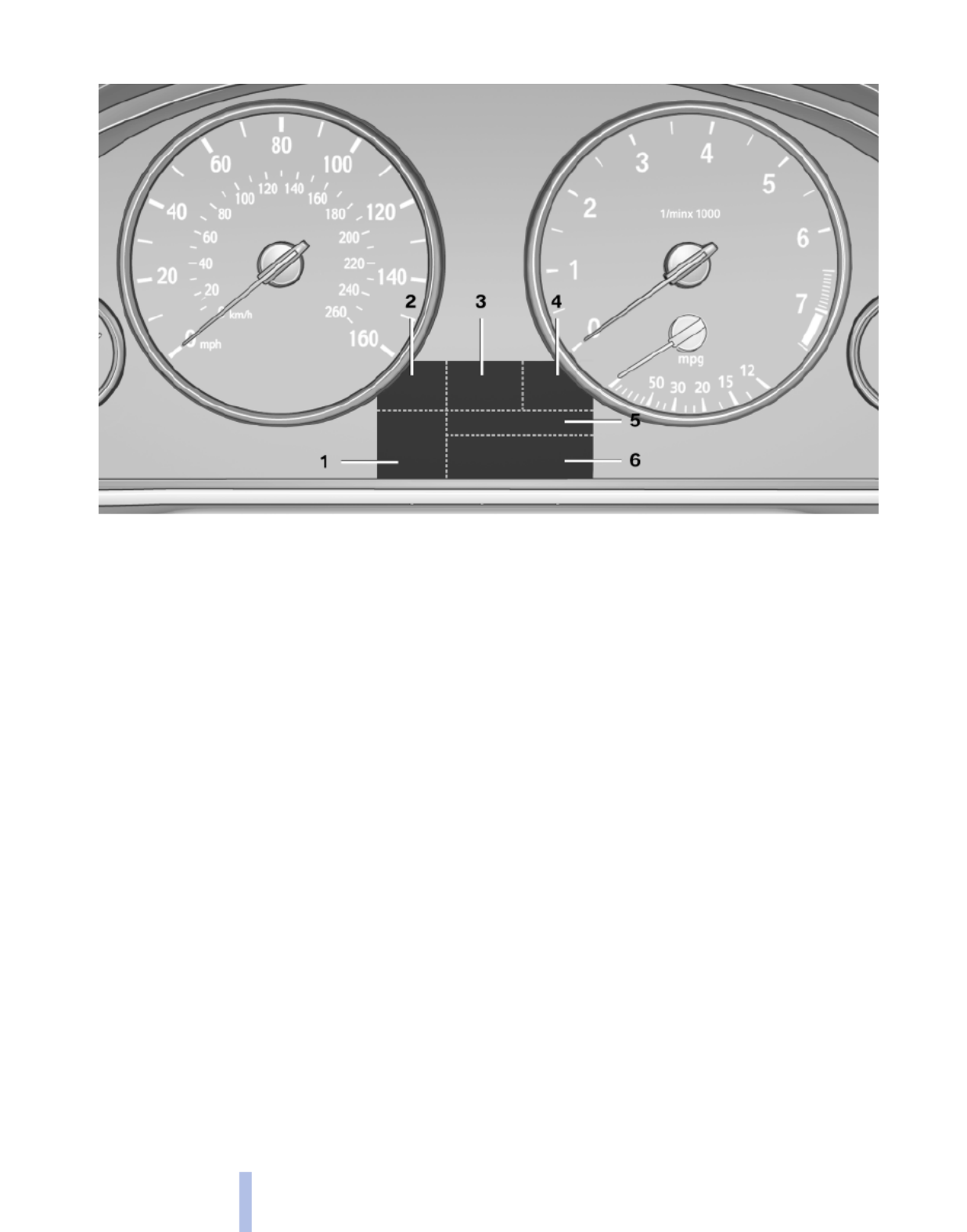
With the Business navigation system or no navigation
1Clock, external temperature 69
2Symbols, e.g., Check Control 74
3Transmission displays 66
4Program display, e.g., Dynamic Driving Con‐
trol*
5Computer 70
6Test messages, e.g., Service display 73
16
Online Edition for Part no. 01 40 2 606 190 - 12 10 500
Cockpit
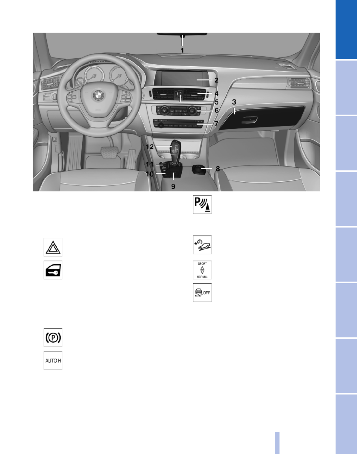
All around the center console
1Headliner 18
2Control Display 19
3Glove compartment 114
4Air vent 106
5Hazard warning system 228
Central locking system 35
6Radio 148
CD/multimedia 155
7Automatic climate control 101
8Controller with buttons 19
9Parking brake 59
Auto Hold* 60
10 PDC Park Distance Con‐
trol* 93
Backup camera* 95
Top View* 97
HDC Hill Descent Control 87
11 Dynamic Driving Control* 89
DSC Dynamic Stability Con‐
trol 86
12 Transmission selector lever
17
Online Edition for Part no. 01 40 2 606 190 - 12 10 500
Reference Mobility Communication Entertainment Navigation Driving tips Controls At a glance

All around the headliner
1Emergency Request* 228
2Panoramic glass sunroof* 45
3Indicator lamp, front passenger
airbag* 82
4Reading lamps* 79
5Interior lamps 79
18
Online Edition for Part no. 01 40 2 606 190 - 12 10 500
Cockpit

3. Move in four directions.
Buttons on controller
Press the button Function
MENU Open the main menu.
RADIO Opens the Radio menu.
CD Opens the CD/Multimedia
menu.
NAV Opens the Navigation map
view.
TEL Opens the Telephone
menu.
BACK Displays the previous
panel.
OPTION Opens the Options menu.
Operating concept
Opening the main menu
Press the button.
The main menu is displayed.
All iDrive functions can be called up via the main
menu.
Selecting menu items
Menu items shown in white can be selected.
1. Turn the controller until the desired menu
item is highlighted.
2. Press the controller.
Menu items in the Owner's Manual
In the Owner's Manual, menu items that can be
selected are set in quotation marks, e.g.,
"Settings".
Changing between panels
After a menu item is selected, e.g., "Radio", a
new panel is displayed. Panels can overlap.
▷Move the controller to the left.
The current panel is closed and the previous
panel is displayed.
The previous panel is opened again by
pressing the BACK button. In this case, the
current panel is not closed.
▷Move the controller to the right.
A new panel is opened on top of the previous
display.
20
Online Edition for Part no. 01 40 2 606 190 - 12 10 500
iDrive
White arrows pointing to the left or right indicate
that additional panels can be opened.
View of an opened menu
When a menu is opened, it generally opens with
the panel that was last selected in that menu. To
display the first panel of a menu:
▷Move the controller to the left repeatedly
until the first panel is displayed.
▷Press the menu button on the controller
twice.
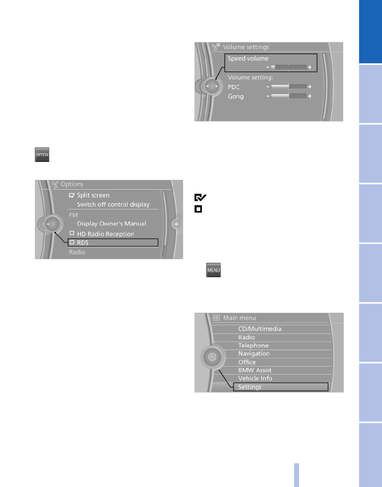
Opening the Options menu
Press the button.
The "Options" menu is displayed.
Additional options: move the controller to the
right repeatedly until the "Options" menu is dis‐
played.
Options menu
The "Options" menu consists of various areas:
▷Screen settings, e.g., "Split screen".
This area remains unchanged.
▷Control options for the selected main menu,
e.g., for "Radio".
▷If applicable, further operating options for
the selected menu, e.g., "Store station".
Changing settings
1. Select a field.
2. Turn the controller until the desired setting
is displayed.
3. Press the controller.
Activating/deactivating the functions
Several menu items are preceded by a check‐
box. It indicates whether the function is acti‐
vated or deactivated. Selecting the menu item
activates or deactivates the function.
The function is activated.
The function is deactivated.
Example: setting the clock
Setting the clock
1. Press the button. The main menu is
displayed.
2. Turn the controller until "Settings" is high‐
lighted, and then press the controller.
3. If necessary, move the controller to the left
to display "Time/Date".
21
Online Edition for Part no. 01 40 2 606 190 - 12 10 500
Reference Mobility Communication Entertainment Navigation Driving tips Controls At a glance

4. Turn the controller until "Time/Date" is high‐
lighted, and then press the controller.
5. Turn the controller until "Time:" is high‐
lighted, and then press the controller.
6. Turn the controller to set the hours and
press the controller.
7. Turn the controller to set the minutes and
press the controller.
Status information
Status field
The following information is displayed in the sta‐
tus field at the top right:
▷Time.
▷Current entertainment source.
▷Sound output, on/off.
▷Wireless network reception strength.
▷Telephone status.
▷Traffic bulletin reception.
Status field symbols
The symbols are grouped as follows.
Radio symbols
Symbol Meaning
Traffic bulletins* switched on.
HD Radio™* is switched on.
Satellite radio* switched on
Telephone symbols
Symbol Meaning
Incoming or outgoing call*
Missed call*
Wireless network reception
strength* Symbol flashes: searching
for network
Wireless network is not available*
Bluetooth* is switched on.
Roaming* is active
Text message* was received.
Check the SIM card*.
SIM card* is blocked.
SIM card* is missing.
Enter the PIN*.
Entertainment symbols
Symbol Meaning
CD/DVD player*
Music collection*
Gracenote® database*
AUX-IN port
USB audio interface*
Mobile phone audio interface*
22
Online Edition for Part no. 01 40 2 606 190 - 12 10 500
iDrive

Additional symbols
Symbol Meaning
Spoken instructions* are switched
off.
Request of the current vehicle posi‐
tion*.
Split screen*
General information
Additional information can be displayed on the
right side of the split screen, e.g., information
from the computer.
In the divided screen view, the so-called split
screen, this information remains visible even
when you change to another menu.
Switching the split screen on and off
1. Press the button.
2. "Split screen"
Selecting the display
1. Press the button.
2. "Split screen"
3. Move the controller until the split screen is
selected.
4. Press the controller or select "Split screen
content".
5. Select the desired menu item.
Programmable memory
buttons
General information
The iDrive functions can be stored on the pro‐
grammable memory buttons and called up di‐
rectly, e.g., radio stations, navigation destina‐
tions, phone numbers and entry points into the
menu.
The settings are stored for the remote control
currently in use.
Saving a function
1. Highlight the function via the iDrive.
2. Press the desired button for more
than 2 seconds.
Running a function
Press the button.
The function will run immediately. This
means, for example, that the number is dialed
when a phone number is selected.
Displaying the button assignment
Use a finger to touch the buttons. Do not wear
gloves or use objects.
The key assignment is displayed at the top edge
of the screen.
▷To display short information: touch the but‐
ton.
▷To display detailed information: touch the
button for an extended period.
23
Online Edition for Part no. 01 40 2 606 190 - 12 10 500
Reference Mobility Communication Entertainment Navigation Driving tips Controls At a glance

Deleting the button assignments
1. Press buttons 1 and 8 simultaneously for
approx. five seconds.
2. "OK"
Entering letters and numbers
1. Turn the controller: select letters or num‐
bers.
2. Select additional letters or numbers if
needed.
3. "OK": confirm the entry.
Symbol Function
Press the controller: delete the letter
or number.
Press the controller for an extended
period: delete all letters or numbers.
Enter a blank space.
Switching between letters and
numbers
Depending on the menu, you can switch be‐
tween entering letters and numbers:
Symbol Function
Enter the letters.
Enter the numbers.
Switching between upper and lower
case letters
Depending on the menu, you can switch be‐
tween entering upper and lower case letters:
Symbol Function
Move the controller up: switch
from upper to lower case letters.
Move the controller up: switch
from lower to upper case letters.
Entry comparison
Entry of names and addresses: the selection is
narrowed down every time a letter is entered and
letters may be added automatically.
The entries are continuously compared to the
data stored in the vehicle.
▷Only those letters are offered during the en‐
try for which data is available.
▷Destination search: town/city names can be
entered using the spelling of language avail‐
able on the Control Display.
24
Online Edition for Part no. 01 40 2 606 190 - 12 10 500
iDrive

Voice activation system*
The concept
▷The voice activation system can be used to
operate functions by means of spoken com‐
mands.
▷Most menu items on the Control Display can
be voiced as commands. The system
prompts you to make your entries.
▷Functions that can only be used when the
vehicle is stationary cannot be operated us‐
ing the voice activation system.
▷The system uses a special microphone on
the driver's side.
▷›...‹ Verbal instructions in the Owner's
Manual to use with the voice activation sys‐
tem.
Requirements
Via the Control Display, set a language that is
also supported by the voice activation system
so that the spoken commands can be identified.
Set the language, refer to page .73
Using voice activation
Activating the voice activation system
1. Press the button on the steering
wheel.
2. Wait for the signal.
3. Say the command.
The command is displayed in the instrument
cluster.
This symbol in the instrument cluster indi‐
cates that the voice activation system is active.
If no other commands are available, continue
operating the function via iDrive.
Terminating the voice activation
system
Briefly press the button on the steering wheel
or ›Cancel‹.
Possible commands
Having possible commands read aloud
The commands available in each case depend
on the menu item selected on the Control Dis‐
play.
To have the available commands read out
loud: ›Voice commands‹
For example, if the "Settings" menu is displayed,
the commands for the settings are read out loud.
Help on the voice activation system
To have the information in the help system read
out loud: ›Help‹
Executing functions using short
commands
Functions on the main menu can be performed
directly by means of short commands, irrespec‐
tive of which menu item is currently selected,
e.g., ›Vehicle status‹.
List of short commands of the voice activation
system, refer to page .243
Example: playing back a CD
1. Switch on the Entertainment sound output
if necessary.
2. Press the button on the steering
wheel.
3. ›C D and multimedia‹
The medium last played is played back.
25
Online Edition for Part no. 01 40 2 606 190 - 12 10 500
Reference Mobility Communication Entertainment Navigation Driving tips Controls At a glance

To switch back and forth repeatedly between
the function displayed last and the page of the
Owner's Manual displayed last, repeat steps 4
and 5. This opens a new panel every time.
Programmable memory buttons
General information
The Owner's Manual can be stored and opened
directly on the Programmable memory buttons.
Storing
1. Select "Owner's Manual" via the iDrive.
2. Press the desired button for more
than 2 seconds.
Executing
Press the button.
The Owner's Manual is displayed im‐
mediately.
28
Online Edition for Part no. 01 40 2 606 190 - 12 10 500
Integrated Owner's Manual in the vehicle

Controls
This chapter is intended to provide you with
information that will give you complete control of
your vehicle. All features and accessories that are
useful for driving and your safety, comfort and
convenience are described here.
Online Edition for Part no. 01 40 2 606 190 - 12 10 500

Loss of the remote controls
Lost remote controls can be blocked by your
service center.
Emergency detection of remote control
It is possible to switch on the ignition or start the
engine in situations such as the following:
▷Interference of radio transmission to remote
control by external sources.
▷Discharged battery in the remote control.
A Check Control message is displayed if an at‐
tempt is made to switch on the ignition or start
the engine.
Starting the engine in case of
emergency detection of remote control
If a corresponding Check Control message ap‐
pears, hold the remote control, as shown,
against the marked area on the steering column
and press the Start/Stop button within 10 sec‐
onds while pressing the brake.
Personal Profile
The concept
Personal Profile concept
You can set several of your vehicle's functions
to suit your personal needs and preferences.
▷The settings are automatically saved in the
profile currently activated.
▷When the vehicle is unlocked, the profile that
was last detected and called up with the re‐
mote control is used.
▷Your personal settings will be recognized
and called up again even if the vehicle has
been used in the meantime by someone else
with another remote control.
The individual settings are stored for three Per‐
sonal Profiles and one guest profile.
Transmitting the settings
Your personal settings can be taken with you to
another vehicle equipped with the Personal Pro‐
file function. For more information, contact your
service center.
Transmission takes place via:
▷The USB interface in the glove compart‐
ment onto a USB device.
Profile management
Opening the profiles
A different profile can be called up than the one
associated with the remote control currently in
use.
1. "Settings"
2. "Profiles"
3. Select a profile.
The profile that is opened is assigned to the re‐
mote control currently in use.
Renaming profiles
1. "Settings"
2. "Profiles"
The current profile is selected.
33
Online Edition for Part no. 01 40 2 606 190 - 12 10 500
Reference Mobility Communication Entertainment Navigation Driving tips Controls At a glance

3. Open "Options".
4. "Rename current profile"
Resetting profiles
The settings of the active profile are reset to
their default values.
1. "Settings"
2. "Profiles"
The current profile is selected.
3. Open "Options".
4. "Reset current profile"
Importing profiles
Existing settings and contacts are overwritten
with the imported profile.
1. "Settings"
2. "Profiles"
3. "Import profile"
4. USB interface*, refer to page : "USB114
device"
Exporting profiles
Most settings of the active profile and the saved
contacts can be exported.
This can be useful for storing and opening per‐
sonal settings, for instance if settings are acci‐
dentally changed or deleted.
1. "Settings"
2. "Profiles"
3. "Export profile"
4. USB interface*, refer to page : "USB114
device"
Using the guest profile
The guest profile can be used to make individual
settings without affecting the three Personal
Profiles.
This can be useful for drivers who are using the
vehicle temporarily and do not have their own
profile.
1. "Settings"
2. "Profiles"
3. The current profile is selected.
4. Open "Guest".
5. Create the settings.
Note: the guest profile cannot be renamed.
Display profile list during start
The profile list can be displayed during each
start for selecting the desired profile.
1. "Settings"
2. "Profiles"
3. Open "Options".
4. "Display user list at startup"
Personal Profile settings
The following functions and settings can be
stored in a profile.
More information on the settings can be found
under:
▷Exterior mirror position*, refer to page .53
▷CD/Multimedia*, refer to page : the au‐155
dio source listened to last.
▷Dynamic Driving Control*, refer to
page : sport program.89
34
Online Edition for Part no. 01 40 2 606 190 - 12 10 500
Opening and closing

▷Driver's seat position, refer to page : au‐37
tomatically retrieved after unlocking.
▷Programmable memory buttons, refer to
page : assignment.23
▷Head-up Display*, refer to page : selec‐99
tion, brightness and position of the display.
▷Headlamp courtesy delay feature, refer to
page : time setting.76
▷Tone, refer to page : tone settings.146
▷Automatic climate control/Automatic cli‐
mate control with enhanced features*, refer
to page : settings.101
▷Navigation*, refer to page : map views,128
route criteria, voice output on/off.
▷PDC Park Distance Control*: adjusting the
volume of the signal tone, refer to
page .93
▷Radio: stored stations, station listened to
last, special settings, refer to page .148
▷Backup camera*, refer to page : selec‐95
tion of functions and type of display.
▷Language on the Control Display, refer to
page .73
▷Triple turn signal activation, refer to
page .62
▷Daytime running lights*, refer to page :77
current setting.
▷Locking the vehicle, refer to page : after36
a brief period or after starting to drive.
Central locking system
The concept
The central locking system becomes active
when the driver's door is closed.
The system simultaneously engages and re‐
leases the locks on the following:
▷Doors.
▷Tailgate.
▷Fuel filler flap.
Operating from the outside
▷Via the remote control.
▷Via the driver's door lock*.
▷Via the door handles of the driver's and front
passenger doors*.
▷Via the button on the tailgate*.
The following takes place simultaneously when
locking/unlocking the vehicle via the remote
control:
▷Anti-theft protection is switched on/off.
Doors cannot be unlocked using the lock
buttons or the door opener.
▷The welcome lamps, interior lamps and
courtesy lamps* are switched on and off.
▷The alarm system*, refer to page , is42
armed or disarmed.
Operating from the inside
Via the button for the central locking system.
If the vehicle has been locked from inside, the
fuel filler flap remains unlocked.
If an accident of a certain severity occurs, the
central locking system unlocks automatically.
The hazard warning system and interior lamps
come on.
35
Online Edition for Part no. 01 40 2 606 190 - 12 10 500
Reference Mobility Communication Entertainment Navigation Driving tips Controls At a glance

Opening and closing: from the
outside
Using the remote control
General information
Take the remote control with you
People or animals left unattended in a
parked vehicle can lock the doors from the in‐
side. Always take the remote control with you
when leaving the vehicle so that the vehicle can
then be opened from the outside.◀
Unlocking
Press the button.
The vehicle is unlocked.
You can set how the vehicle is to be unlocked.
The setting is stored for the remote control cur‐
rently in use.
1. "Settings"
2. "Door locks"
3. "Unlock button:"
4. Select the desired function:
▷"Driver's door only"
Only the driver's door and the fuel filler
flap are unlocked. Pressing again un‐
locks the entire vehicle.
▷"All doors"
The entire vehicle is unlocked.
Convenient opening
The remote control can be used to simultane‐
ously open the windows and the glass sunroof*.
Press and hold the button on the re‐
mote control.
The windows and the glass sunroof* open.
Releasing the button stops the motion.
Locking
Press the button on the remote control.
Do not lock from the outside
Do not lock the vehicle from the outside if
there are people in it, as the vehicle cannot be
unlocked from inside without special knowl‐
edge.◀
Switching on the interior lamps,
courtesy lamps*, and welcome lamps
Press the button on the remote control
with the vehicle locked.
Panic mode*
You can trigger the alarm system if you find
yourself in a dangerous situation.
Press the button on the remote control
for at least 3 seconds.
To switch off the alarm: press any button.
Switching on the headlamp courtesy
delay feature
Briefly press the button on the remote
control.
The duration can be set.
Opening the tailgate
Press the button on the remote control
for approx. 1 second and release.
The tailgate opens, regardless of whether it was
previously locked or unlocked.
The tailgate pivots back and up when it opens.
Ensure that adequate clearance is available be‐
fore opening.
36
Online Edition for Part no. 01 40 2 606 190 - 12 10 500
Opening and closing

Any unauthorized modifications or changes to
these devices could void the user's authority to
operate this equipment.
Using the door lock
General information
Do not lock from the outside
Do not lock the vehicle from the outside if
there are people in it, as the vehicle cannot be
unlocked from inside without special knowl‐
edge.◀
Remove the key before pulling the door
handle
Before pulling the outside door handle, remove
the key to avoid damaging the paintwork and the
key.◀
In some country-specific versions, the alarm
system* is triggered if the vehicle is unlocked via
the door lock.
Manual operation
If an electrical malfunction occurs, lock or unlock
the vehicle using a key via the door lock on the
driver's door.
Locking the doors and tailgate at once*
In some vehicle equipment versions, only the
driver's door can be locked via the door lock.
To lock all doors and the tailgate at once:
1. With the doors closed, lock the vehicle using
the button for the central locking system in
the interior.
2. Unlock and open the driver's or front pas‐
senger door.
3. Lock the vehicle.
▷Lock the driver's door using the
integrated key in the door lock, or
▷Press down the lock button of the front
passenger door and close the door from
the outside.
The fuel filler flap can only be locked using the
remote control.
Opening and closing: from the
inside
Unlocking and opening*
▷Either unlock the doors together using the
button for the central locking system and
then pull the door handle above the armrest
or
▷Pull the door opener twice individually on
each door: the first time unlocks the door,
the second time opens it.
Locking and unlocking
Press the button in the vehicle.
The doors and the tailgate are locked or
unlocked when the front doors are closed, but
they are not secured against theft.
The fuel filler flap remains unlocked.
Automatic locking
The setting is stored for the remote control cur‐
rently in use.
1. "Settings"
38
Online Edition for Part no. 01 40 2 606 190 - 12 10 500
Opening and closing
The vehicle is locked completely.
Automatic trunk lid operation*
Adjusting the opening height
You can set how far the tailgate should open.
Adjusting the opening height
When adjusting the opening height, en‐
sure that there is a clearance of at least 4 in/
10 cm above the tailgate. Otherwise, the ceiling
may not be high enough for the open tailgate if
the load situation changes.◀
1. "Settings"
2. "Tailgate"
3. Turn the controller until the desired opening
height is selected.
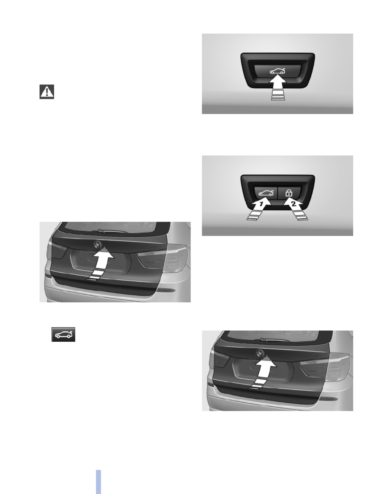
Opening
The tailgate opens fully.
▷Press the button on the exterior of the tail‐
gate.
▷Press the button on the remote
control or in the driver's footwell.
Pressing the button again stops the motion.
The opening process is interrupted as well:
▷When the vehicle starts moving.
▷By pressing the button in the driver's foot‐
well.
▷By pressing the button on the inside of the
tailgate.
Closing
▷Press the button on the inside of the tailgate.
The tailgate closes automatically.
Pressing again stops the motion.
With Comfort Access:
▷Press the button, arrow 1, on the inside of
the tailgate.
The tailgate closes automatically.
Pressing again stops the motion.
▷Press the button, arrow 2.
Tailgate closes automatically and the vehi‐
cle is locked.
▷Press the button on the exterior of the tail‐
gate.
Pressing again stops the motion.
40
Online Edition for Part no. 01 40 2 606 190 - 12 10 500
Opening and closing
The closing process is not interrupted when the
vehicle starts moving.
Danger of pinching
Make sure that the closing path of the tail‐
gate is clear; otherwise, injuries may result.◀
Do not place the remote control in the
cargo area
Take the remote control with you and do not
leave it in the cargo area; otherwise, the remote
control may be locked inside the vehicle when
the tailgate is closed.◀
Manual operation
In the event of an electrical malfunction, operate
the unlocked tailgate manually with a slow and
smooth motion.
Comfort Access*
The concept
The vehicle can be accessed without activating
the remote control.
All you need to do is to have the remote control
with you, e.g., in your jacket pocket.
The vehicle automatically detects the remote
control when it is nearby or in the passenger
compartment.
Comfort Access supports the following func‐
tions:
▷Unlocking/locking of the vehicle.
▷Unlocking of the tailgate separately.
▷Starting the engine.
Functional requirements
▷There are no external sources of interfer‐
ence nearby.
▷To lock the vehicle, the remote control must
be located outside of the vehicle.
▷The next unlocking and locking cycle is not
possible until after approx. 2 seconds.
▷The engine can only be started if the remote
control is inside the vehicle.
Comparison with ordinary remote
control
The functions can be controlled by pressing the
buttons or via Comfort Access.
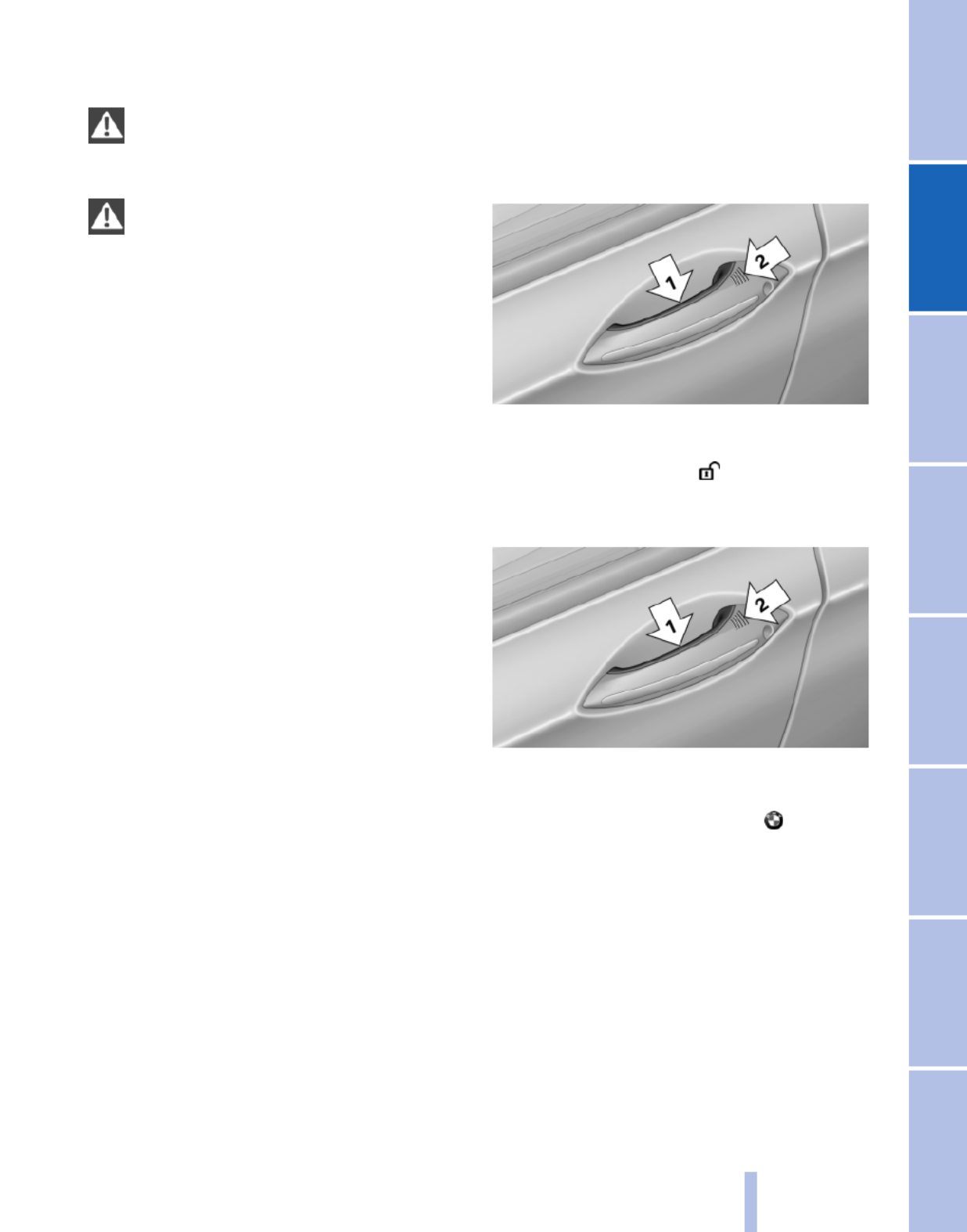
Unlocking
Grasp the door handle on the driver's or front
passenger door completely, arrow 1. This cor‐
responds to pressing the button.
Locking
Press the area on the door handle, arrow 2, with
your finger for approx. 1 second.
This corresponds to pressing the button.
To save battery power, ensure that the ignition
and all electronic systems and/or power con‐
sumers are switched off before locking the ve‐
hicle.
Convenient closing
Press the area, arrow 2, with your finger and
hold.
The windows and the glass sunroof* close as
well.
Unlocking the tailgate separately
Press the button on the exterior of the tailgate.
41
Online Edition for Part no. 01 40 2 606 190 - 12 10 500
Reference Mobility Communication Entertainment Navigation Driving tips Controls At a glance

This corresponds to pressing the button.
Do not place the remote control in the
cargo area
Take the remote control with you and do not
leave it in the cargo area; otherwise, the remote
control may be locked inside the vehicle when
the tailgate is closed.◀
Ignition on
Pressing the Start/Stop button switches the ig‐
nition on.
When doing so, do not depress the brake pedal;
otherwise, the engine will start.
Malfunction
Comfort Access may not function properly if it
experiences interference from external sources
such as mobile phones, metal objects, overhead
power lines, transmission towers, etc.
If this occurs, open or close the vehicle using the
buttons on the remote control or use a key in the
door lock.
To subsequently start the engine, hold the re‐
mote control against the marked area on the
steering column, refer to page .33
Alarm system*
The concept
The vehicle alarm system responds to:
▷Opening of a door, the hood or the tailgate.
▷Movements in the vehicle: interior motion
sensor, refer to page .43
▷Changes in the vehicle tilt, e.g., during at‐
tempts to steal a wheel or tow the car.
▷Interruptions in battery voltage.
The alarm system briefly indicates tampering:
▷By sounding an acoustic alarm.
▷By switching on the hazard warning system.
▷By flashing the high beams.
Arming and disarming the alarm
system
General information
When you lock or unlock the vehicle, either with
the remote control or at the door lock*, the alarm
system is armed or disarmed at the same time.
Door lock and armed alarm system
Unlocking via the door lock will trigger the alarm
on some country-specific versions.
Tailgate and armed alarm system
The tailgate can be opened using the remote
control, even if the alarm system is armed.
Press the button on the remote control
for approx. 1 second and release.
After the tailgate is closed, it is locked and moni‐
tored again by the alarm system. The hazard
warning system flashes once.
In some vehicle equipment variants, the tailgate
can only be opened using the remote control if
the vehicle was unlocked first.
Panic mode*
Press the button on the remote control
for at least 3 seconds.
Switching off the alarm
▷Unlock the vehicle using the remote control.
▷With Comfort Access: If you are carrying the
remote control with you, pull on the door
handle.
42
Online Edition for Part no. 01 40 2 606 190 - 12 10 500
Opening and closing
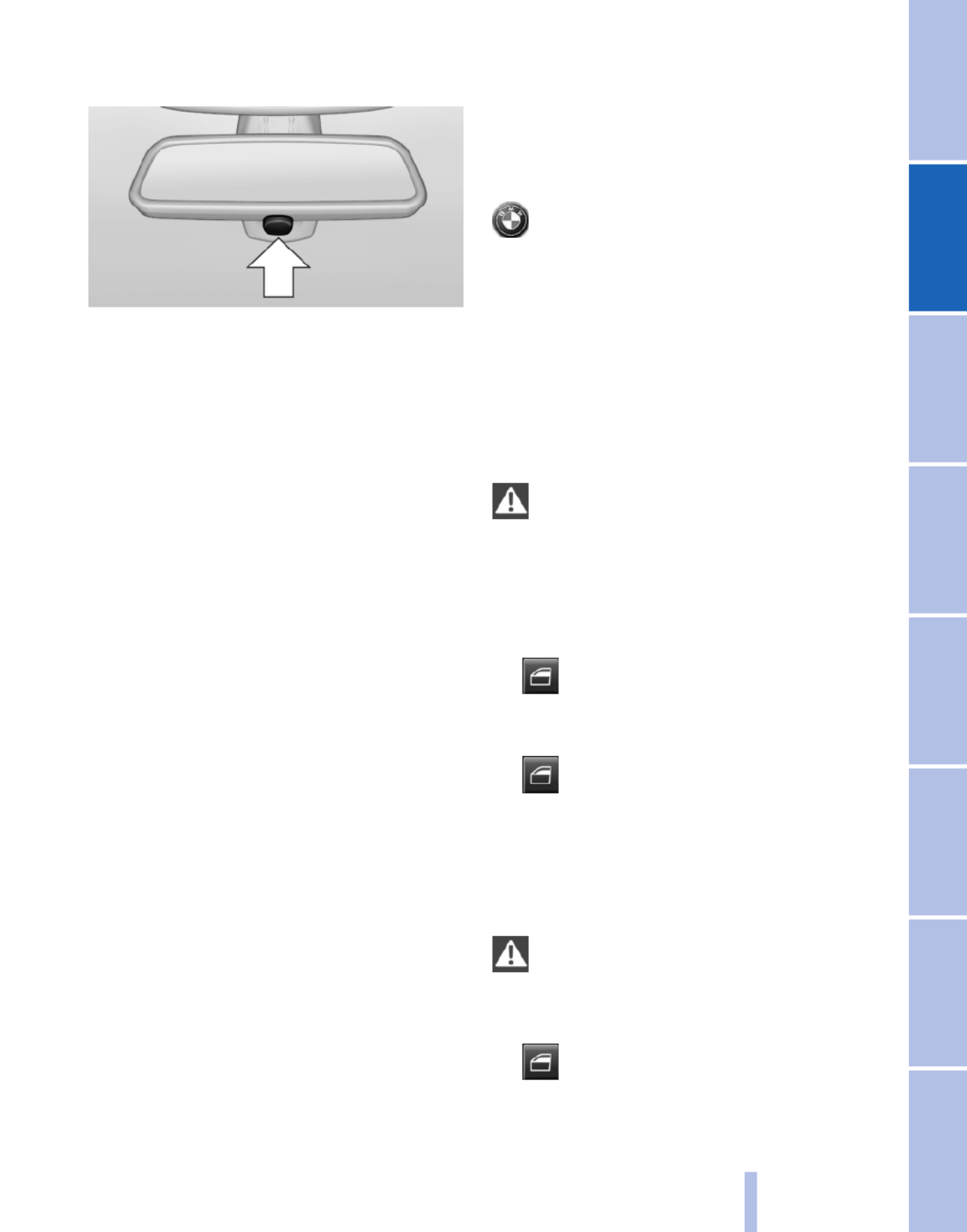
Indicator lamp on the interior rearview
mirror
▷The indicator lamp flashes briefly every
2 seconds:
The system is armed.
▷The indicator lamp flashes after locking:
The doors, hood or tailgate is not closed
properly, but the rest of the vehicle is se‐
cured.
After 10 seconds, the indicator lamp flashes
continuously. The interior motion sensor is
not active.
▷The indicator lamp goes out after unlocking:
The vehicle has not been tampered with.
▷The indicator lamp flashes after unlocking
until the engine is started, but no longer than
approx. 5 minutes:
An alarm has been triggered.
Tilt alarm sensor
The tilt of the vehicle is monitored.
The alarm system responds in situations such
as attempts to steal a wheel or tow the car.
Interior motion sensor
The windows and glass sunroof must be closed
for the system to function properly.
Avoiding unintentional alarms
The tilt alarm sensor and interior motion sensor
can be switched off together, such as in the fol‐
lowing situations:
▷In automatic car washes
▷In duplex garages.
▷During transport on car-carrying trains, at
sea or on a trailer.
▷When animals are to remain in the vehicle.
Switching off the tilt alarm sensor and
interior motion sensor
Press the button on the remote control
twice in succession.
The indicator lamp lights up for approx. 2 sec‐
onds and then flashes continuously.
The tilt alarm sensor and interior motion sensor
are switched off until the vehicle is locked again.
Power windows
General information
Take the remote control with you
Take the remote control with you when
leaving the vehicle so that children, for example,
cannot operate the power windows and injure
themselves.◀
Opening
▷ Press the switch to the resistance
point.
The window opens while the switch is held.
▷ Press the switch beyond the resist‐
ance point.
The window opens automatically.
Pressing again stops the motion.
Closing
Danger of pinching
Monitor the closing process and make
sure that the closing path of the window is clear;
otherwise, injuries may result.◀
▷ Pull the switch to the resistance point.
The window closes while the switch is held.
43
Online Edition for Part no. 01 40 2 606 190 - 12 10 500
Reference Mobility Communication Entertainment Navigation Driving tips Controls At a glance

▷ Pull the switch beyond the resistance
point.
The window closes automatically.
Pressing the switch stops the motion.
Convenient operation, refer to page , via the36
remote control.
Convenient closing, refer to page 41, with Com‐
fort Access*.
Pinch protection
If the closing force exceeds a specific value as a
window closes, the closing action is interrupted.
The window reopens slightly.
Danger of pinching even with pinch pro‐
tection
Even with the pinch protection system, check
that the window's closing path is clear; other‐
wise, the closing action may not stop in certain
situations, e.g., if thin objects are present.◀
Window accessories
Do not install any accessories in the range
of movement of the windows; otherwise, the
pinch protection system will be impaired.◀
Closing without the pinch protection
system
Danger of pinching
Monitor the closing process and make
sure that the closing path of the window is clear;
otherwise, injuries may result.◀
For example, if there is an external danger or if
ice on the windows prevents a window from
closing normally, proceed as follows:
1. Pull the switch past the resistance point and
hold it there.
Pinch protection is limited and the window
reopens slightly if the closing force exceeds
a certain value.
2. Pull the switch past the resistance point
again within approx. 4 seconds and hold it
there.
The window closes without pinch protec‐
tion.
Safety switch
The safety switch in the driver's door can be
used to prevent children, for example, from
opening and closing the rear windows using the
switches in the rear.
Switching on and off
Press the button.
The LED lights up if the safety function
is switched on.
Safety switch for rear operation
Press the safety switch when transporting
children in the rear; otherwise, injury may result
if the windows are closed without supervision.◀
Initializing after a power failure
After a power failure, it may only be possible to
operate the windows to a limited extent.
Initializing the system
Danger of pinching
Monitor the closing process and make
sure that the closing path of the window is clear;
otherwise, injuries may result.◀
Pull the switch past the resistance point
and hold it there until the window is closed.
Roller sunblinds*
Roller sunblinds for the rear side
windows
Pull out the roller sunblind at the loop and hook
it onto the bracket.
Do not open the window while the roller
sunblind is raised.
Do not open the window while the roller sunblind
is raised; otherwise, there is a risk of damage at
high speeds that may result in personal injury.◀
44
Online Edition for Part no. 01 40 2 606 190 - 12 10 500
Opening and closing
Danger of pinching even with pinch pro‐
tection
Despite the pinch protection system, check that
the roof's closing path is clear; otherwise, the
closing action may not be interrupted in certain
extreme situations, such as when thin objects
are present.◀
Closing without the pinch protection
system
For example, if there is an external danger, pro‐
ceed as follows:
1. Press the switch forward beyond the resist‐
ance point and hold.
Pinch protection is limited and the roof re‐
opens slightly if the closing force exceeds a
certain value.
2. Press the switch forward again beyond the
resistance point and hold until the roof
closes without pinch protection.
Initializing after a power failure
After a power failure, it may only be possible to
operate the roof to a limited extent.
Initializing the system
The system can be initialized when the vehicle
is stationary and the engine is running.
Danger of pinching
Monitor the closing process and make
sure that the closing path of the glass sunroof is
clear; otherwise, injuries may result.◀
Press and hold the switch until
the initialization has been com‐
pleted:
▷Initialization begins within
15 seconds and is completed
when the sunroof and sliding
visor are completely closed.
▷The roof closes without pinch protection.
46
Online Edition for Part no. 01 40 2 606 190 - 12 10 500
Opening and closing

Unbuckling the belt
1. Hold the belt firmly.
2. Press the red button in the belt buckle.
3. Guide the belt back into its reel.
Safety belt reminder for the driver's and
front passenger seat
The indicator lamp flashes or lights up
and a signal sounds. Make sure that the
safety belts are positioned correctly.
The safety belt reminder is active at speeds
above approx. 5 mph/8 km/h. It can also be ac‐
tivated if objects are placed on the front pas‐
senger seat.
Damage to safety belts
In the case of strain caused by accidents or
damage:
Have the safety belts, including the safety belt
tensioners, replaced and have the belt anchors
checked.
Checking and replacing safety belts
Have the work performed only by your
service center; otherwise, it cannot be ensured
that this safety feature will function properly.◀
Front head restraints
Correctly adjusted head restraint
A correctly adjusted head restraint reduces the
risk of injury to cervical vertebrae in the event of
an accident.
Adjusting the head restraint
Correctly adjust the head restraints of all
occupied seats; otherwise, there is an increased
risk of injury in an accident.◀
Height
Adjust the head restraint so that its center is ap‐
proximately at ear level.
Distance
Adjust the distance so that the head restraint is
as close as possible to the back of the head.
If necessary, adjust the distance by adjusting
the tilt of the backrest.
Active head restraint
In the event of a rear-end collision with a certain
severity, the active head restraint automatically
reduces the distance from the head.
Reduced protective function
▷Do not use seat or head restraint cov‐
ers.
▷Do not hang objects, e.g., clothes hangers,
on the head restraints.
▷Only attach accessories approved by BMW
to the seat or head restraint.
Otherwise, the protective function of the active
head restraint will be impaired and the personal
safety of the occupants will be endangered.◀
Removing
The head restraints cannot be removed.
Rear head restraints
Correctly adjusted head restraint
A correctly adjusted head restraint reduces the
risk of injury to cervical vertebrae in the event of
an accident.
Adjusting the head restraint
Correctly adjust the head restraints of all
occupied seats; otherwise, there is an increased
risk of injury in an accident.◀
Height
Adjust the head restraint so that its center is ap‐
proximately at ear level.
51
Online Edition for Part no. 01 40 2 606 190 - 12 10 500
Reference Mobility Communication Entertainment Navigation Driving tips Controls At a glance
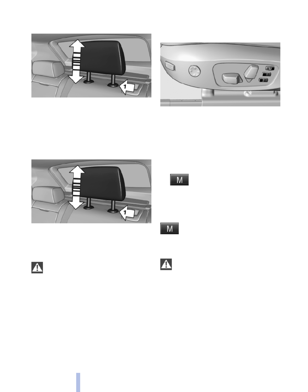
Adjusting the height: outer head
restraints
▷To raise: pull.
▷To lower: press the button, arrow 1, and
push the head restraint down.
Removing
Only remove the head restraint if no one will be
sitting in the seat in question.
1. Pull the head restraint upward as far as pos‐
sible.
2. Press the button, arrow 1, and pull the head
restraint out completely.
Before transporting passengers
Reinstall the head restraint before trans‐
porting anyone in the seat; otherwise, the pro‐
tective function of the head restraint is unavail‐
able.◀
Seat and mirror memory*
General information
Two different driver's seat and exterior mirror
positions can be stored and retrieved for each
remote control. Settings for the backrest width
and lumbar support are not stored in memory.
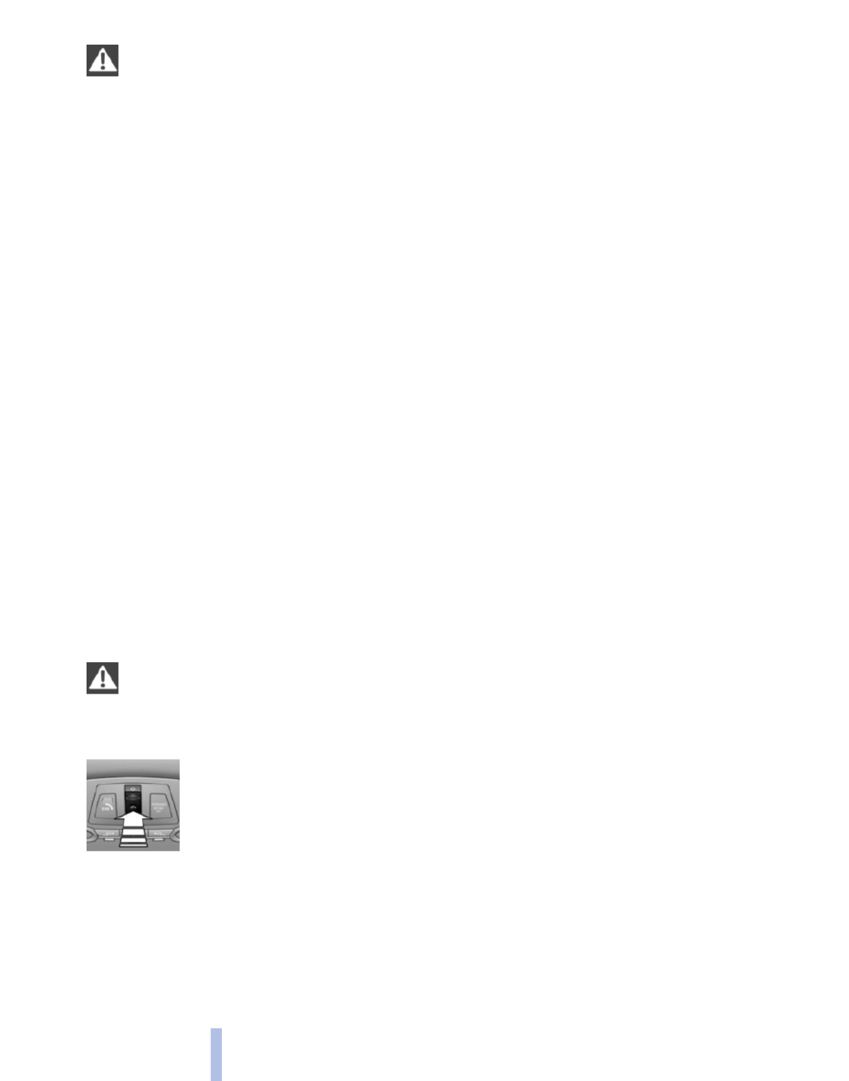
Storing
1. Switch on the ignition.
2. Set the desired position.
3. Press the button. The LED in the
button lights up.
4. Press the desired button 1 or 2. The LED
goes out.
If the M button is pressed accidentally:
Press the button again.
The LED goes out.
Calling up settings
Do not retrieve the memory while driving
Do not retrieve the memory setting while
driving, as an unexpected movement of the seat
or steering wheel could result in an accident.◀
Comfort function
1. Open the driver's door.
2. Switch off the ignition.
3. Briefly press the desired button 1 or 2.
The corresponding seat position is performed
automatically.
The procedure stops when a switch for adjust‐
ing the seat or one of the buttons is pressed.
52
Online Edition for Part no. 01 40 2 606 190 - 12 10 500
Adjusting

Safety mode
1. Close the driver's door or switch on the ig‐
nition.
2. Press and hold the desired button 1 or 2 until
the adjustment procedure is completed.
Calling up of a seat position
deactivated
After a brief period, the calling up of stored seat
positions is deactivated to save battery power.
To reactivate calling up of a seat position:
▷Open or close the door or tailgate.
▷Press a button on the remote control.
▷Press the Start/Stop button.
Mirrors
Exterior mirrors
At a glance
1Adjusting
2Left/right, Automatic Curb Monitor*
3Fold in and out*
General information
The mirror on the passenger side is more curved
than the driver's side mirror.
Estimating distances correctly
Objects reflected in the mirror are closer
than they appear. Do not estimate the distance
to the traffic behind you based on what you see
in the mirror, as this will increase your risk of an
accident.◀
The mirror setting is stored for the remote con‐
trol currently in use. When the vehicle is un‐
locked via the remote control, the position is au‐
tomatically retrieved if the setting for this
function is active.
Selecting a mirror
To change over to the other mirror:
Slide the mirror changeover switch.
Adjusting electrically
The setting corresponds to the direction
in which the button is pressed.
Saving positions*
Seat and mirror memory, refer to page 52
Adjusting manually
If an electrical malfunction occurs, for example,
press the edges of the mirror glass.
Automatic Curb Monitor*
When the reverse gear is engaged, the mirror
glass tilts downward slightly on the front pas‐
senger side. This improves your view of the curb
and other low-lying obstacles when parking, for
example.
Activating
1. Slide the mirror changeover switch
to the driver's side mirror position.
2. Engage transmission position R.
Deactivating
Slide the mirror changeover switch to the pas‐
senger's side mirror position.
Fold in and out*
Press the button.
Possible up to approx. 15 mph/20 km/h.
For example, this is advantageous
▷In car washes.
53
Online Edition for Part no. 01 40 2 606 190 - 12 10 500
Reference Mobility Communication Entertainment Navigation Driving tips Controls At a glance
▷In narrow streets.
▷For folding back mirrors that were folded
away manually.
Mirrors that were folded in are folded out auto‐
matically at a speed of approx. 25 mph/40 km/h.
Fold in the mirror in a car wash
Before entering an automatic car wash,
fold in the exterior mirrors by hand or with the
button; otherwise, they could be damaged, de‐
pending on the width of the vehicle.◀
Automatic heating
Both exterior mirrors are automatically heated
whenever the engine is running.
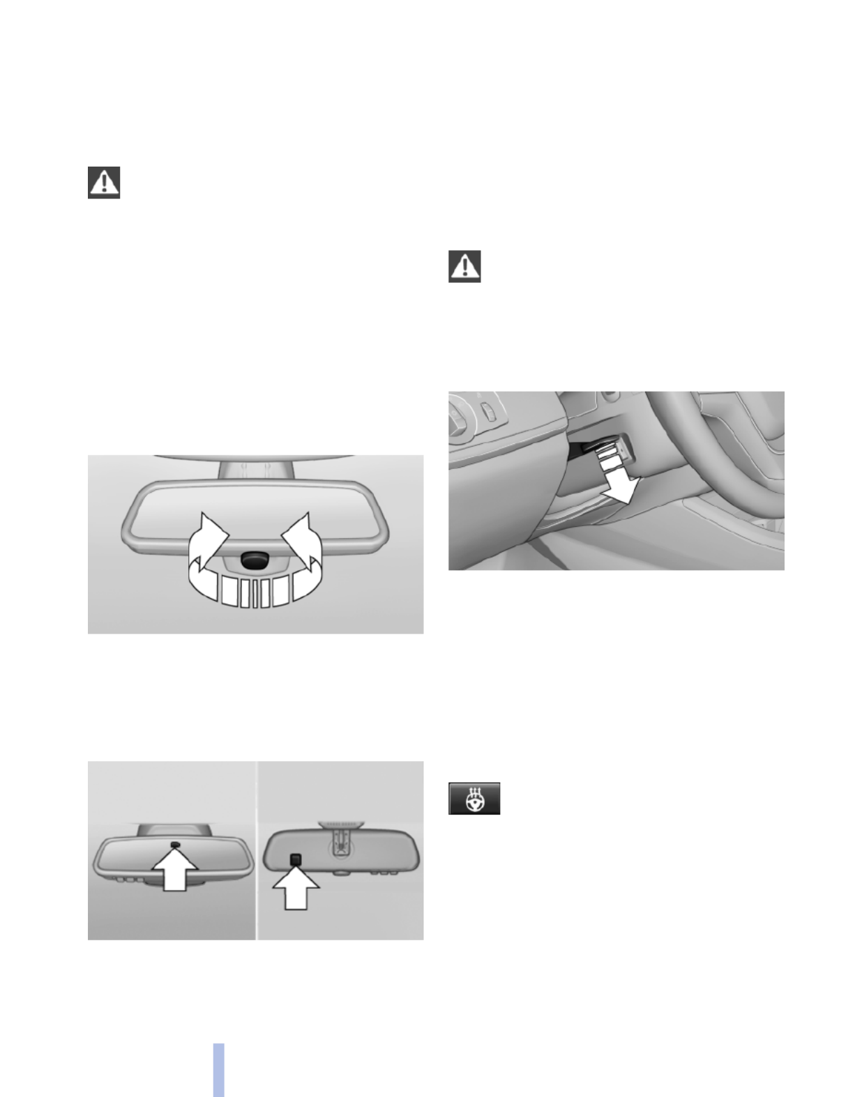
Interior rearview mirror
Reducing the blinding effect
From behind when driving at night: turn the
knob.
Interior mirror, automatic dimming
feature*
Photocells are used for control:
▷In the mirror glass.
▷On the back of the mirror.
For proper operation:
▷Keep the photocells clean.
▷Do not cover the area between the inside
rearview mirror and the windshield.
Steering wheel
General information
Do not adjust while driving
Do not adjust the steering wheel while
driving; otherwise, an unexpected movement
could result in an accident.◀
Adjusting
1. Fold the lever down.
2. Move the steering wheel to the preferred
height and angle to suit your seating posi‐
tion.
3. Fold the lever back.
Steering wheel heating*
Switching on/off
Press the button.
▷On: the LED lights up.
▷Off: the LED goes out.
54
Online Edition for Part no. 01 40 2 606 190 - 12 10 500
Adjusting

Transporting children safely
The right place for children
Note
Children in the vehicle
Do not leave children unattended in the
vehicle; otherwise, they could endanger them‐
selves and other persons, e.g., by opening the
doors.◀
Children should always be in the rear
Accident research shows that the safest place
for children is in the back seat.
Transporting children in the rear
Only transport children younger than
13 years of age or shorter than 5 ft/150 cm in the
rear in child restraint fixing systems provided in
accordance with the age, weight and size of the
child; otherwise, there is an increased risk of in‐
jury in an accident.
Children 13 years of age or older must wear a
safety belt as soon as a suitable child restraint
fixing system can no longer be used, due to their
age, weight and size.◀
Children on the front passenger seat
Should it ever be necessary to use a child re‐
straint fixing system in the front passenger seat,
make sure that the front, knee and side airbags
on the front passenger side are deactivated. Au‐
tomatic deactivation of front passenger airbags,
refer to page .81
Deactivating the front passenger airbags
If a child restraint fixing system is used in
the front passenger seat, the front passenger
airbags must be deactivated; otherwise, there is
an increased risk of injury to the child when the
airbags are triggered, even with a child restraint
fixing system.◀
Installing child restraint fixing
systems
Before mounting
Before mounting child restraint fixing systems,
ensure that the rear seat backrests are locked.
Notes
Manufacturer's information for child re‐
straint fixing systems
To select, mount and use child restraint fixing
systems, observe the information provided by
the system manufacturer; otherwise, the pro‐
tective effect can be impaired.◀
On the front passenger seat
After installing a child restraint fixing system in
the front passenger seat, make sure that the
front, knee and side airbags on the front pas‐
senger side are deactivated.
Deactivate the front passenger airbags auto‐
matically, refer to page .81
Deactivating the front passenger airbags
If a child restraint fixing system is used in
the front passenger seat, the front passenger
airbags must be deactivated; otherwise, there is
an increased risk of injury to the child when the
airbags are triggered, even with a child restraint
fixing system.◀
Seat position and height
Before installing a child restraint fixing system,
move the front passenger seat as far back as
possible and adjust its height to the highest po‐
sition to obtain the best possible position for the
belt and to offer optimal protection in the event
of an accident.
Do not change the seat position and height after
this.
55
Online Edition for Part no. 01 40 2 606 190 - 12 10 500
Reference Mobility Communication Entertainment Navigation Driving tips Controls At a glance

Backrest width*
Before installing a child restraint fixing system in
the front passenger seat, open the backrest
width completely. Do not change the backrest
width again and do not call up a memory posi‐
tion.
Backrest width for the child seat
Before installing a child restraint fixing
system in the front passenger seat, the backrest
width must be opened completely. Do not
change the adjustment after this; otherwise, the
stability of the child seat will be reduced.◀
Child seat security
The rear safety belts and the front passenger
safety belt can be locked against pulling out for
mounting the child restraint fixing systems.
Locking the safety belt
1. Pull out the belt webbing completely.
2. Secure the child restraint fixing system with
the belt.
3. Allow the belt webbing to be pulled in and
pull it taut against the child restraint fixing
system. The safety belt is locked.
Unlocking the safety belt
1. Unbuckle the belt buckle.
2. Remove the child restraint fixing system.
3. Allow the belt webbing to be pulled in com‐
pletely.
LATCH child restraint fixing
system
LATCH: Lower Anchors and Tether for CHil‐
dren.
Note
Manufacturer's information for LATCH
child restraint fixing systems
To mount and use the LATCH child restraint fix‐
ing systems, observe the operating and safety
information from the system manufacturer; oth‐
erwise, the level of protection may be reduced.◀
Mounts for the lower LATCH anchors
Correctly engage the lower LATCH an‐
chors
Make sure that the lower LATCH anchors have
properly engaged and that the child restraint fix‐
ing system is resting snugly against the back‐
rest; otherwise, the degree of protection offered
may be reduced.◀
Before mounting the LATCH child restraint fix‐
ing system, pull the belt away from the child re‐
straint fixing system.
Mounts for the lower LATCH anchors are lo‐
cated in the gap between the seat and backrest.
Mounting LATCH child restraint fixing
systems
1. Mount the child restraint fixing system; refer
to the operating instructions of the system.
2. Ensure that both LATCH anchors are prop‐
erly connected.
56
Online Edition for Part no. 01 40 2 606 190 - 12 10 500
Transporting children safely

Child restraint fixing system with a
tether strap
Mounting points
There are three mounting points for the upper
retaining strap of LATCH child restraint fixing
systems.
LATCH mounting eyes
Only use the mounting eyes for the upper
LATCH retaining strap to secure child restraint
fixing systems; otherwise, the mounting eyes
could be damaged.◀
Retaining strap guide
Retaining strap
Make sure that the upper retaining strap is
not routed over the head restraints or sharp
edges and is free of twisting on its way to the
upper mounting point; otherwise, the belt can‐
not properly secure the child restraint fixing sys‐
tem in an accident.◀
1Direction of travel
2Head restraint.
3Hook for upper retaining strap
4Mounting point/eye
5Seat backrest
6Upper retaining strap
Attaching the upper retaining strap to
the mounting point
1. Raise the head restraint.
2. Guide the upper retaining strap between the
supports of the head restraint.
3. Attach the hooks of the retaining strap to the
mounting eyes.
4. Tighten the retaining strap by pulling it
down.
5. Lower the head restraint.
Locking the doors and
windows
Rear doors
Push the locking lever on the rear doors down.
The door can now be opened from the outside
only.
Safety switch for the rear
Press the button on the driver's door if
children are being transported in the
rear.
This locks various functions so that they cannot
be operated from the rear: safety switch, refer to
page .44
57
Online Edition for Part no. 01 40 2 606 190 - 12 10 500
Reference Mobility Communication Entertainment Navigation Driving tips Controls At a glance

Driving
Start/Stop button
The concept
Pressing the Start/Stop button
switches the ignition on or off and
starts the engine.
The engine starts if the brake
pedal is pressed when you press
the Start/Stop button.
Ignition on
Press the Start/Stop button and do not press on
the brake pedal at the same time.
All vehicle systems are ready for operation.
Most of the indicator and warning lamps in the
instrument cluster light up for varying lengths of
time.
To save battery power when the engine is off,
switch off the ignition and any unnecessary
electronic systems/power consumers.
The ignition switches off automatically:
▷When the vehicle is locked, if the low beams
are switched on.
▷Shortly before the battery is discharged
completely, so that the engine can still be
started.
▷If the engine is switched off and the ignition
is switched on, the system automatically
switches to the radio ready state when the
door is opened if the lights are switched off
or the daytime running lights are switched
on.
Ignition off
Press the Start/Stop button again and do not
press on the brake pedal at the same time.
All indicator lamps in the instrument cluster go
out.
To save battery power when the engine is off,
switch off the ignition and any unnecessary
electronic systems/power consumers.
Transmission position P with the ignition
off
When the ignition is switched off, position P is
engaged automatically. When in an automatic
car wash, for example, ensure that the ignition is
not switched off accidentally.◀
When the vehicle is locked using the central
locking system, the ignition switches off auto‐
matically.
Radio ready state
This state can only be reached by pressing the
Start/Stop button briefly to switch off the engine
while it is running.
Some electronic systems/power consumers re‐
main ready for operation.
Radio ready state switches off automatically:
▷After approx. 8 minutes.
▷When the vehicle is locked using the central
locking system.
Starting the engine
General information
Enclosed areas
Do not let the engine run in enclosed
areas; otherwise, breathing of exhaust fumes
may lead to loss of consciousness and death.
The exhaust gases contain carbon monoxide, an
odorless and colorless but highly toxic gas.◀
Unattended vehicle
Do not leave the car unattended with the
engine running; otherwise, it presents a poten‐
tial source of danger.
Before leaving the car with the engine running,
set the parking brake and place the transmission
in position P or neutral to prevent the car from
moving.◀
58
Online Edition for Part no. 01 40 2 606 190 - 12 10 500
Driving

Frequent starting in quick succession
Avoid repeated futile attempts at starting
the car and avoid starting the car frequently in
quick succession. Otherwise, the fuel is not
burned or is inadequately burned, and there is
the danger of overheating and damaging the
catalytic converter.◀
Do not wait for the engine to warm up while the
vehicle remains stationary. Start driving at mod‐
erate engine speeds.
Automatic transmission*
Starting the engine
Press on the brake pedal and
press the Start/Stop button.
The ignition is activated automat‐
ically for a brief period and is
stopped as soon as the engine
starts.
Engine stop
General information
Take the remote control with you
Take the remote control with you when
leaving the vehicle so that children, for example,
cannot operate the windows and injure them‐
selves.◀
Set the parking brake and further secure
the vehicle as required
Set the parking brake firmly when parking; oth‐
erwise, the vehicle could roll. On steep upward
and downward inclines, further secure the vehi‐
cle, for example, by turning the steering wheel in
the direction of the curb. ◀
Automatic transmission*
Switching off the engine
1. Engage transmission position P with the ve‐
hicle stopped.
2. Press the Start/Stop button.
The engine is switched off.
The radio ready state is switched on.
3. Set the parking brake.
Before driving into a car wash
The vehicle is able to roll when the following
steps are adhered to:
1. Depress the brake pedal.
2. Engage transmission position N.
3. Release the parking brake or deactivate Au‐
tomatic Hold.
4. Switch the engine off.
Transmission position P with the ignition
off
When the ignition is switched off, position P is
engaged automatically. When in an automatic
car wash, for example, ensure that the ignition is
not switched off accidentally.◀
Transmission position P is engaged automati‐
cally:
▷When the ignition is switched off.
▷After approx. 15 minutes if the vehicle is not
moved.
Parking brake
The concept
The parking brake is primarily intended to pre‐
vent the vehicle from rolling while parked; it
brakes the rear wheels.
In cars with automatic transmission*:
The parking brake can be set manually or auto‐
matically:
▷Manual: by pulling and pushing the switch.
▷Automatic: by activating Automatic Hold.
59
Online Edition for Part no. 01 40 2 606 190 - 12 10 500
Reference Mobility Communication Entertainment Navigation Driving tips Controls At a glance
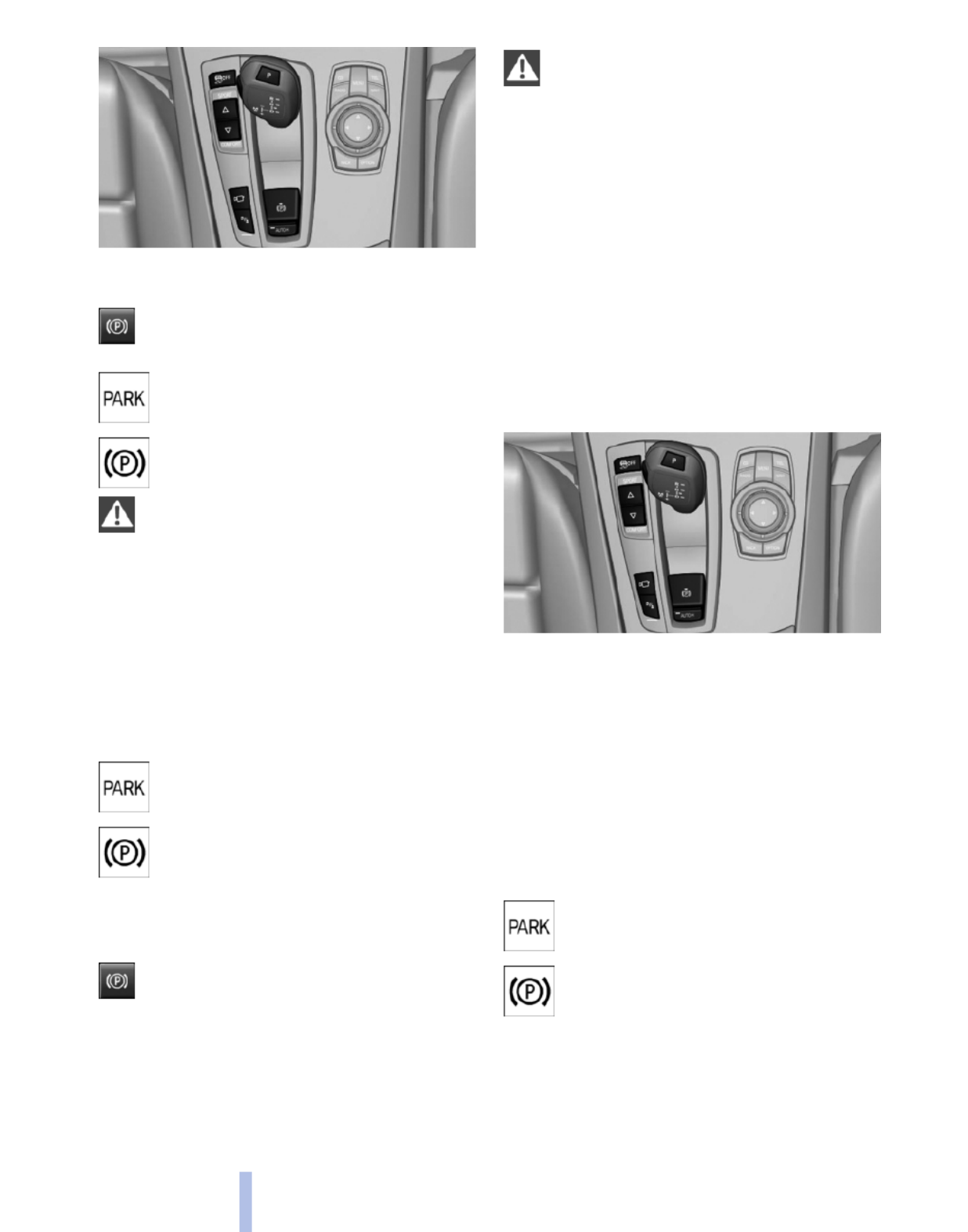
Setting
Pull the switch.
The LED lights up.
The indicator lamp lights up in red. The
parking brake is set.
Indicator lamp in Canadian models
Set the parking brake and further secure
the vehicle as required
Set the parking brake firmly when parking;
otherwise, the vehicle could roll. On steep
upward and downward inclines, further secure
the vehicle, for example, by turning the steering
wheel in the direction of the curb. ◀
While driving
Use while driving:
Pull the switch and hold it. The vehicle brakes
hard while the button is being pulled.
The indicator lamp lights up in red, a sig‐
nal sounds and the brake lamps light up.
Indicator lamp in Canadian models
If the vehicle is braked to a speed of ap‐
prox. 2 mph/3 km/h, the parking brake
remains set.
Releasing
Automatic transmission*: Press the
switch while the brake is pressed or trans‐
mission position P is engaged.
The LED and indicator lamp go out.
The parking brake is released.
Take the remote control with you
Take the remote control with you when
leaving the vehicle so that children, for example,
cannot release the parking brake.◀
Automatic Hold*
The concept
This system assists the driver by automatically
setting and releasing the brake, such as when
moving in stop-and-go traffic.
The vehicle is automatically held in place when
it is stationary.
On inclines, the system prevents the vehicle
from rolling backward when driving away.
For your safety
Under the following conditions, Automatic Hold
is automatically deactivated and the parking
brake is set:
▷The engine is switched off.
▷A door is opened and driver's safety belt is
unbuckled.
▷The moving vehicle is brought to a standstill
using the parking brake.
The indicator lamp switches from green
to red and the letters AUTO H go out.
Indicator lamp in Canadian models
Before driving away:
▷Release the parking brake manually.
▷Reactivate Automatic Hold.
60
Online Edition for Part no. 01 40 2 606 190 - 12 10 500
Driving

Triple turn signal activation
Press the lever to the resistance point.
The turn signal flashes three times.
The function can be activated or deactivated:
1. "Settings"
2. "Lighting"
3. "Triple turn signal"
Signaling briefly
Press the lever to the resistance point and hold
it there for as long as you want the turn signal to
flash.
High beams, headlamp flasher
▷High beams, arrow 1.
▷Headlamp flasher, arrow 2.
Washer/wiper system
Switching the wipers on/off and brief
wipe
Do not switch on the wipers if frozen
Do not switch on the wipers if they are fro‐
zen onto the windshield; otherwise, the wiper
blades and the windshield wiper motor may be
damaged.◀
Switching on
Press the wiper levers up.
The lever automatically returns to its initial po‐
sition when released.
▷Normal wiping speed: press up once.
The wipers switch to intermittent operation
when the vehicle is stationary.
▷Fast wiping speed: press up twice or press
once beyond the resistance point.
The wipers switch to normal speed when the
vehicle is stationary.
Switching off and brief wipe
Press the wiper levers down.
The lever automatically returns to its initial po‐
sition when released.
62
Online Edition for Part no. 01 40 2 606 190 - 12 10 500
Driving
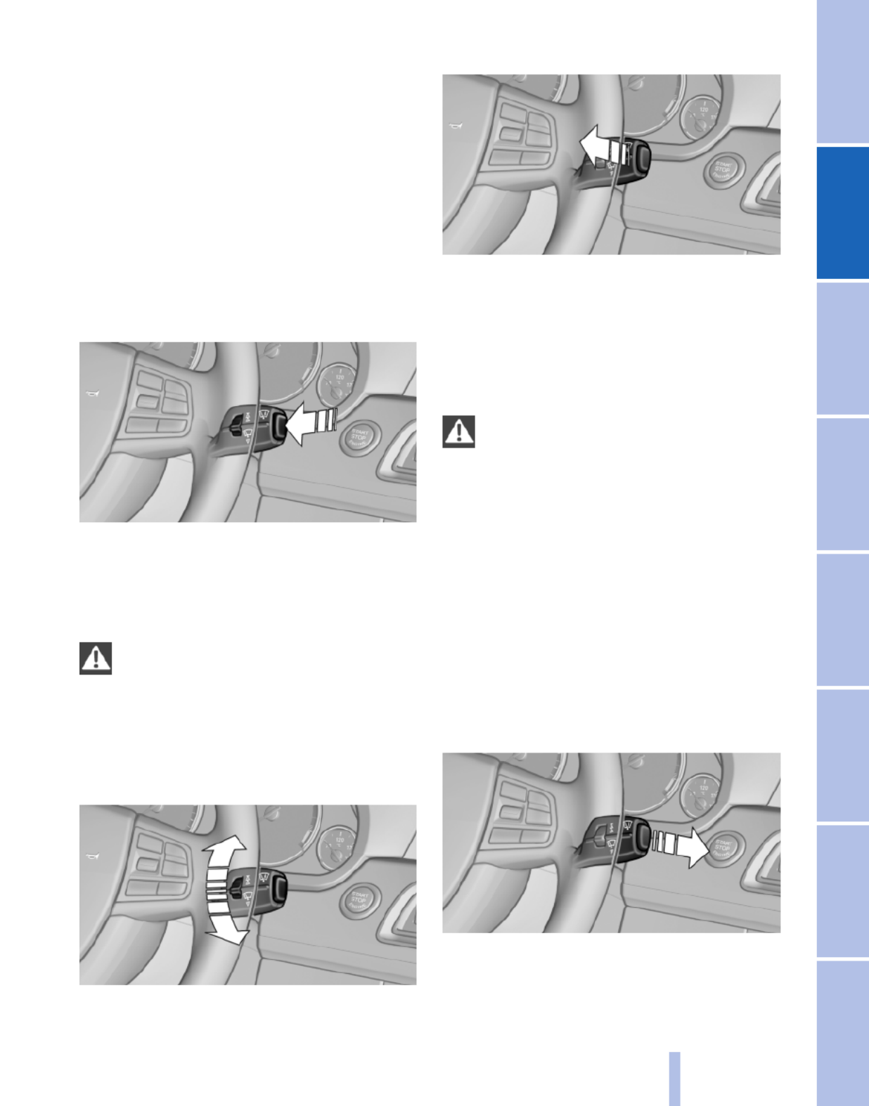
▷Brief wipe: press down once.
▷To switch off normal wipe: press down once.
▷To switch off fast wipe: press down twice.
Rain sensor*
The concept
The time between wipes is controlled automat‐
ically and depends on the intensity of the rainfall.
The sensor is located on the windshield, directly
in front of the interior rearview mirror.
Activating/deactivating the rain sensor
Press the button on the wiper lever.
When activated, the wipers move over the wind‐
shield once.
The LED in the steering column stalk lights up.
Deactivate the rain sensor in car washes
Deactivate the rain sensor when passing
through an automatic car wash; otherwise, dam‐
age could be caused by undesired wiper activa‐
tion.◀
Rain sensor sensitivity
Turn the thumbwheel.
Clean the windshield, headlamps*
Pull the lever.
The system sprays washer fluid on the wind‐
shield and activates the wipers briefly.
In addition, the headlamps are cleaned at regular
intervals when the vehicle lights are switched
on.
Do not use the washer system at freezing
temperatures
Do not use the washers if there is any danger
that the fluid will freeze on the windshield; oth‐
erwise, your vision could be obscured. For this
reason, use antifreeze.
Avoid using the washer when the reservoir is
empty; otherwise, you could damage the
pump.◀
Windshield washer nozzles
The washer jets are automatically heated*
whenever the ignition is switched on.
Switching on the rear window wiper
Press the lever forward: intermittent wipe. When
reverse gear is engaged, the system switches to
continuous operation.
63
Online Edition for Part no. 01 40 2 606 190 - 12 10 500
Reference Mobility Communication Entertainment Navigation Driving tips Controls At a glance

To clean the rear window, press the lever further
forward.
Fold-out position of the wipers
Required when changing the wiper blades or
under frosty conditions, for example.
1. Switch off the ignition.
2. Under frosty conditions, ensure that the
wiper blades are not frozen onto the wind‐
shield.
3. Press the wiper lever up beyond the point of
resistance and hold it for approx. 3 seconds,
until the wiper remains in a nearly vertical
position.
After the wipers are folded back down, the wiper
system must be reactivated.
Fold the wipers back down
Before switching the ignition on, fold the
wipers back down to the windshield; otherwise,
the wipers may become damaged when they are
switched on.◀
1. Switch on the ignition.
2. Press the wiper levers down. The wipers
move to their resting position and are ready
for operation.
Washer fluid
General information
Antifreeze for washer fluid
Antifreeze is flammable. Therefore, keep
it away from sources of ignition.
Only keep it in the closed original container and
inaccessible to children.
Follow the instructions on the container.◀
Washer fluid reservoir
Adding washer fluid
Only add washer fluid when the engine is
cool, and then close the cover completely to
avoid contact between the washer fluid and hot
engine parts.
Otherwise, there is the danger of fire and a risk
to personal safety if the fluid is spilled.◀
All washer nozzles are supplied from one reser‐
voir.
Fill with water and – if required – with a washer
antifreeze, according to the manufacturer's rec‐
ommendations.
Mix the washer fluid before adding to maintain
the correct mixing ratio.
Capacity
Approx. 5.3 US quarts/ 5 liters
Automatic transmission with
Steptronic*
Transmission positions
D Drive, automatic position
Position for normal vehicle operation. All for‐
ward gears are available.
R is Reverse
Select only when the vehicle is stationary.
N is Neutral
Use in automatic car washes, for example. The
vehicle can roll.
When the ignition is switched off, refer to
page , position P is engaged automatically.58
P Park
Select only when the vehicle is stationary. The
drive wheels are blocked.
P is engaged automatically:
64
Online Edition for Part no. 01 40 2 606 190 - 12 10 500
Driving

▷After the engine is switched off, if the car is
in radio ready state, refer to page 58, or if the
ignition is switched off, refer to page 58, and
if position R or D is engaged.
▷If the ignition is switched off and position N
is engaged.
▷If the safety belt is unbuckled, the driver's
door is opened, and the brake pedal is not
pressed while the vehicle is stationary and
transmission position R or D is engaged.
Kickdown
Kickdown is used to achieve maximum driving
performance. Press on the accelerator beyond
the resistance point at the full throttle position.
Engaging the transmission position
▷Transmission position P can only be disen‐
gaged if the engine is running and the brake
pedal is pressed.
▷With the vehicle stationary, press on the
brake pedal before shifting out of P or N;
otherwise, the shift command will not be
executed: shift lock.
Depress the brake until you start driv‐
ing
To prevent the vehicle from creeping after
you select a driving position, maintain pres‐
sure on the brake pedal until you are ready
to start.◀
Engaging D, R and N
Briefly push the selector lever in the desired di‐
rection, beyond a resistance point if necessary.
After releasing the selector lever, it returns to its
center position.
Press the Unlock button to:
▷Engage R.
▷Shift out of P.
Engaging P
Press button P.
Sport program and manual mode M/S
Activating the sport program
Push the selector lever to the left out of trans‐
mission position D.
DS is displayed in the instrument cluster.
This position is recommended for a perform‐
ance-oriented driving style.
65
Online Edition for Part no. 01 40 2 606 190 - 12 10 500
Reference Mobility Communication Entertainment Navigation Driving tips Controls At a glance

Activating the M/S manual mode
Push the selector lever to the left out of trans‐
mission position D.
Push the selector lever forward or backward.
Manual mode becomes active and the gear is
changed.
The engaged gear is displayed in the instrument
cluster, e.g., M1.
▷To shift down: press the selector lever for‐
ward.
▷To shift up: press the selector lever back‐
ward.
The transmission only shifts up or down if the
rpm and vehicle speed are appropriate. If the
engine speed is too high, the transmission does
not shift down.
The selected gear is briefly displayed in the in‐
strument cluster, followed by the current gear.
Ending the sport program/manual
mode
Push the selector lever to the right.
D is displayed in the instrument cluster.
Shift paddles for Sport automatic
transmission*
The shift paddles on the steering wheel allow
you to shift gears quickly while keeping both
hands on the steering wheel.
If the shift paddles on the steering wheel are
used to shift gears in automatic mode, the trans‐
mission temporarily switches to manual mode.
If the shift paddles are not used and the vehicle
is not accelerated for a certain time, the system
switches back into automatic mode if the selec‐
tor lever is in D.
▷Shift up: pull right shift paddle.
▷Shift down: pull left shift paddle.
The vehicle only shifts up or down at appropriate
engine and road speeds, e.g., it does not shift
down if the engine speed is too high.
The selected gear is briefly displayed in the in‐
strument cluster, followed by the current gear.
Displays in the instrument cluster
The transmission position is dis‐
played, for instance, P.
66
Online Edition for Part no. 01 40 2 606 190 - 12 10 500
Driving

Displays
Instrument cluster
At a glance
1Fuel gauge
2Speedometer
3Indicator/warning lamps
4Tachometer
5Oil temperature
6Electronic displays
7External temperature, clock
8Miles, trip miles
9Reset miles
Fuel gauge
The vehicle inclination may
cause the display to vary.
Notes on refueling, refer to
page .204
Range
After the reserve range is
reached:
▷A Check Control message is
displayed briefly.
▷The remaining range is
shown on the computer.
▷When a dynamic driving style is used, such
as when corners are taken rapidly, engine
functions are not ensured.
The Check Control message appears continu‐
ously below a range of approx. 30 miles/50 km.
Refuel promptly
Refuel no later than at a range 30 miles/
50 km, or engine functions are not ensured and
damage may occur.◀
67
Online Edition for Part no. 01 40 2 606 190 - 12 10 500
Reference Mobility Communication Entertainment Navigation Driving tips Controls At a glance

Displaying the cruising range
1. "Settings"
2. "Info display"
3. "Additional indicators"
Tachometer
Always avoid engine speeds in the red warning
field. In this range, the fuel supply is interrupted
to protect the engine.
Current fuel consumption
Displays the current fuel con‐
sumption. You can check
whether you are currently driving
in an efficient and environmen‐
tally-friendly manner.
Displaying the current fuel
consumption
1. "Settings"
2. "Info display"
3. "Additional indicators"
The bar display for the current fuel consumption
is displayed in the instrument cluster.
Energy recovery
The energy of motion of the ve‐
hicle is converted to electrical en‐
ergy while coasting. The vehicle
battery is partially charged and
fuel consumption can be low‐
ered.
Engine oil temperature
▷Cold engine: the pointer is at
the low temperature end.
Drive at moderate engine and
vehicle speeds.
▷Normal operating tempera‐
ture: the pointer is in the mid‐
dle or in the left half of the
temperature display.
▷Hot engine: the pointer is at the high tem‐
perature end. A Check Control message is
displayed in addition.
Odometer and trip odometer
▷Odometer, arrow 1.
▷Trip odometer, arrow 2.
68
Online Edition for Part no. 01 40 2 606 190 - 12 10 500
Displays

Resetting the trip odometer
Press the knob.
▷The odometer is displayed
when the ignition is switched
off.
▷When the ignition is switched
on, the trip odometer is reset.
External temperature
External temperature warning
If the display drops to +37 ℉/
+3 ℃, a signal sounds.
A Check Control message is dis‐
played.
There is the increased danger of
ice.
Ice on roads
Even at temperatures above +37 ℉/+3 ℃,
there can be a risk of ice on roads.
Therefore, drive carefully on bridges and shady
roads, for example, to avoid the increased dan‐
ger of an accident.◀
Time
The time is displayed in the in‐
strument cluster.
Date
The date is displayed in the in‐
strument cluster.
Selection lists in the
instrument cluster
The concept
The following can be operated using the buttons
and the thumbwheel on the steering wheel and
the display in the instrument cluster:
▷Current audio source.
▷Redial on telephone*.
▷Activation of the voice activation system*.
Activating a list and creating the
setting
Press a button on the right side of the steering
wheel or turn the thumbwheel to activate the re‐
quired list.
Create the setting using the thumbwheel.
69
Online Edition for Part no. 01 40 2 606 190 - 12 10 500
Reference Mobility Communication Entertainment Navigation Driving tips Controls At a glance
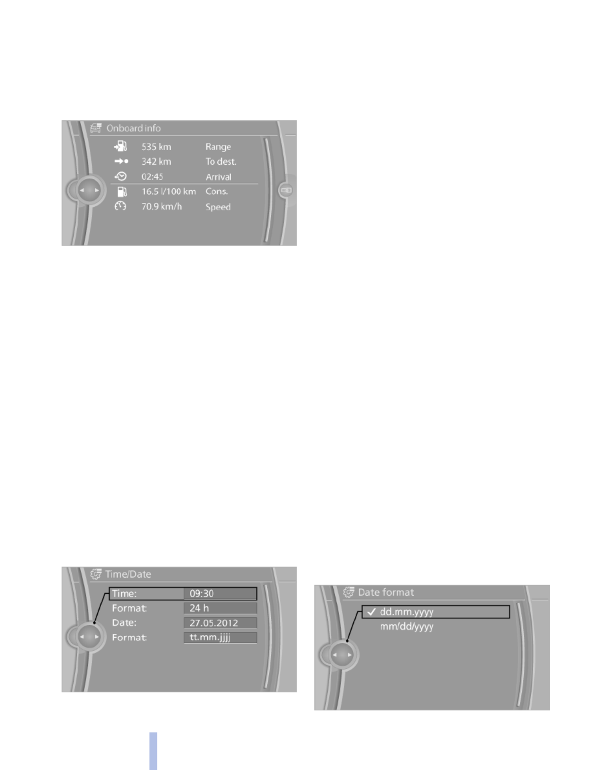
Resetting the fuel consumption and
speed
1. "Vehicle Info"
2. "Onboard info"
3. "Cons." or "Speed"
4. "Yes"
Settings on the Control
Display
Time
Setting the time zone*
1. "Settings"
2. "Time/Date"
3. "Time zone"
4. Select the desired time zone.
The time zone is stored.
Setting the time
1. "Settings"
2. "Time/Date"
3. "Time:"
4. Turn the controller until the desired hours
are displayed.
5. Press the controller.
6. Turn the controller until the desired minutes
are displayed.
7. Press the controller.
The time is stored.
Setting the time format
1. "Settings"
2. "Time/Date"
3. "Format:"
4. Select the desired format.
The time format is stored.
Date
Setting the date
1. "Settings"
2. "Time/Date"
3. "Date:"
4. Turn the controller until the desired day is
displayed.
5. Press the controller.
6. Make the necessary settings for the month
and year.
The date is stored.
Setting the date format
1. "Settings"
2. "Time/Date"
3. "Format:"
4. Select the desired format.
72
Online Edition for Part no. 01 40 2 606 190 - 12 10 500
Displays

Data regarding the maintenance status or legally
mandated inspections of the vehicle are auto‐
matically transmitted to your service center be‐
fore a service due date, Automatic Service Re‐
quest, refer to page .195
Detailed information on service
requirements
More information on the scope of service re‐
quired can be displayed on the Control Display.
1. "Vehicle Info"
2. "Vehicle status"
3. "Service required"
Required maintenance procedures and le‐
gally mandated inspections are displayed.
4. Select an entry to call up detailed informa‐
tion.
Symbols
Symbols Description
No service is currently required.
The deadline for service or a le‐
gally mandated inspection is
approaching. Please make a
service appointment.
The service deadline has al‐
ready passed.
Entering appointment dates
Enter the dates for the required inspections.
Ensure that the vehicle date and time are set
correctly.
1. "Vehicle Info"
2. "Vehicle status"
3. "Service required"
4. "§ Vehicle inspection"
5. "Date:"
6. Create the settings.
7. Confirm.
The entered date is stored.
Automatic Service Request*
Data regarding the maintenance status or legally
mandated inspections of the vehicle are auto‐
matically transmitted to your service center be‐
fore a service due date.
You can check when your service center was
notified.
1. "Vehicle Info"
2. "Vehicle status"
3. Open "Options".
4. "Last Service Request"
Check Control
The concept
The Check Control system monitors functions
in the vehicle and notifies you of malfunctions in
the monitored systems.
A Check Control message is displayed as a
combination of indicator or warning lamps and
text messages in the instrument cluster and in
the Head-up Display*.
In addition, an acoustic signal may be output and
a text message may appear on the Control Dis‐
play.
Indicator/warning lamps
The indicator and warning lamps can light up in
a variety of combinations and colors.
74
Online Edition for Part no. 01 40 2 606 190 - 12 10 500
Displays
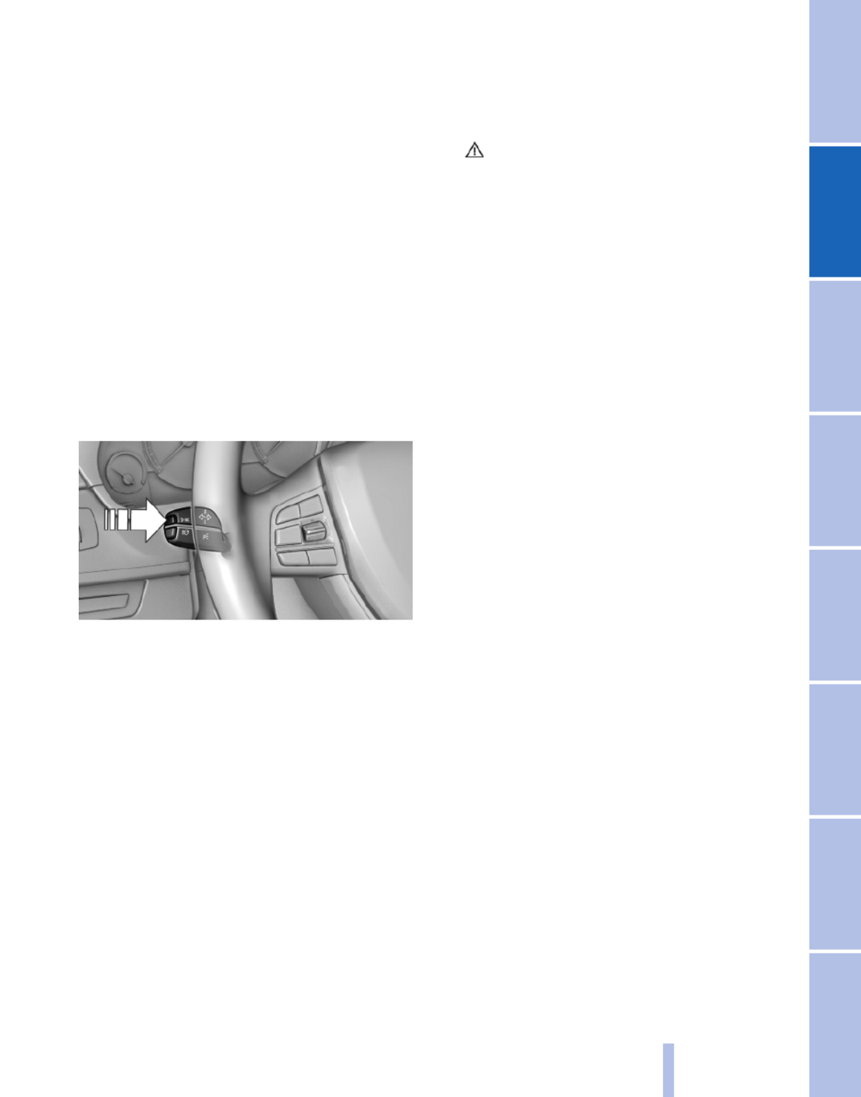
Several of the lamps are checked for proper
functioning and light up temporarily when the
engine is started or the ignition is switched on.
Text messages
Text messages in combination with a symbol in
the instrument cluster explain a Check Control
message and the meaning of the indicator and
warning lamps.
Supplementary text messages
Addition information, such as on the cause of a
fault or the required action, can be called up via
Check Control. The supplementary text of ur‐
gent messages is displayed automatically.
It is shown on the Control Display.
Hiding Check Control messages
Press the computer button on the turn signal
lever.
▷Some Check Control messages are dis‐
played continuously and are not cleared un‐
til the malfunction is eliminated. If several
malfunctions occur at once, the messages
are displayed consecutively.
These messages can be hidden for approx.
8 seconds. After this time, they are dis‐
played again automatically.
▷Other Check Control messages are hidden
automatically after approx. 20 seconds.
They are stored and can be displayed again
later.
Displaying stored Check Control
messages
1. "Vehicle Info"
2. "Vehicle status"
3. "Check Control"
4. Select the text message.
Messages after trip completion
Malfunctions indicated during a trip are dis‐
played again after the ignition is switched off.
75
Online Edition for Part no. 01 40 2 606 190 - 12 10 500
Reference Mobility Communication Entertainment Navigation Driving tips Controls At a glance

Lamps
At a glance
1Rear fog lamps*
2Front fog lamps*
3Automatic headlamp control/adaptive light
control*/High-beam Assistant*/welcome
lamps*/daytime running lights
4Lamps off/daytime running lights*
5Parking lamps/daytime running lights*
6Low beams/welcome lamps/High-beam As‐
sistant*
7Instrument lighting
8Headlamp range control*
Parking lamps/low beams,
headlamp control
Parking lamps
Switch position : the vehicle lamps light
up on all sides, e.g., for parking.
Do not use the parking lamps for extended pe‐
riods; otherwise, the battery may become dis‐
charged and it would then be impossible to start
the engine.
When parking, it is preferable to switch on the
one-sided roadside parking lamps, refer to
page .77
Low beams
Switch position with the ignition switched
on: the low beams light up.
Welcome lamps
When parking the vehicle, leave the switch in
position or : the parking and interior
lamps light up briefly when the vehicle is un‐
locked.
Activating/deactivating
1. "Settings"
2. "Lighting"
3. "Welcome light"
The setting is stored for the remote control cur‐
rently in use.
Headlamp courtesy delay feature
The low beams stay lit for a short while after the
ignition is switched off, if the lamps are switched
off and the headlamp flasher is switched on.
Setting the duration
1. "Settings"
2. "Lighting"
3. "Pathway light.: s"
4. Set the duration.
76
Online Edition for Part no. 01 40 2 606 190 - 12 10 500
Lamps

▷When the windshield in front of the interior
rearview mirror is fogged over, dirty or cov‐
ered with stickers, etc.
Camera
The camera is located on the front of the interior
rearview mirror.
Keep the area in front of the interior rearview
mirror clear.
Fog lamps
Front fog lamps*
The parking lamps or low beams must be
switched on.
Press the button. The green indicator
lamp lights up.
If the automatic headlamp control, refer to
page , is activated, the low beams will come77
on automatically when you switch on the front
fog lamps.
Instrument lighting
Adjusting
The parking lamps or low beams
must be switched on to adjust the
brightness.
Adjust the brightness using the
thumbwheel.
Interior lamps
General information
The interior lamps, footwell lamps, entry lamps
and courtesy lamps are controlled automati‐
cally.
The brightness of some of these lamps is influ‐
enced by the thumbwheel for the instrument
lighting.
1Interior lamps
2Reading lamp
Switching the interior lamps on and off
Press the button.
To switch off permanently: press the button for
approx. 3 seconds.
To clear this setting: press the button.
Reading lamps
Press the button.
Reading lamps are located at the front and rear
next to the interior lamps.
79
Online Edition for Part no. 01 40 2 606 190 - 12 10 500
Reference Mobility Communication Entertainment Navigation Driving tips Controls At a glance
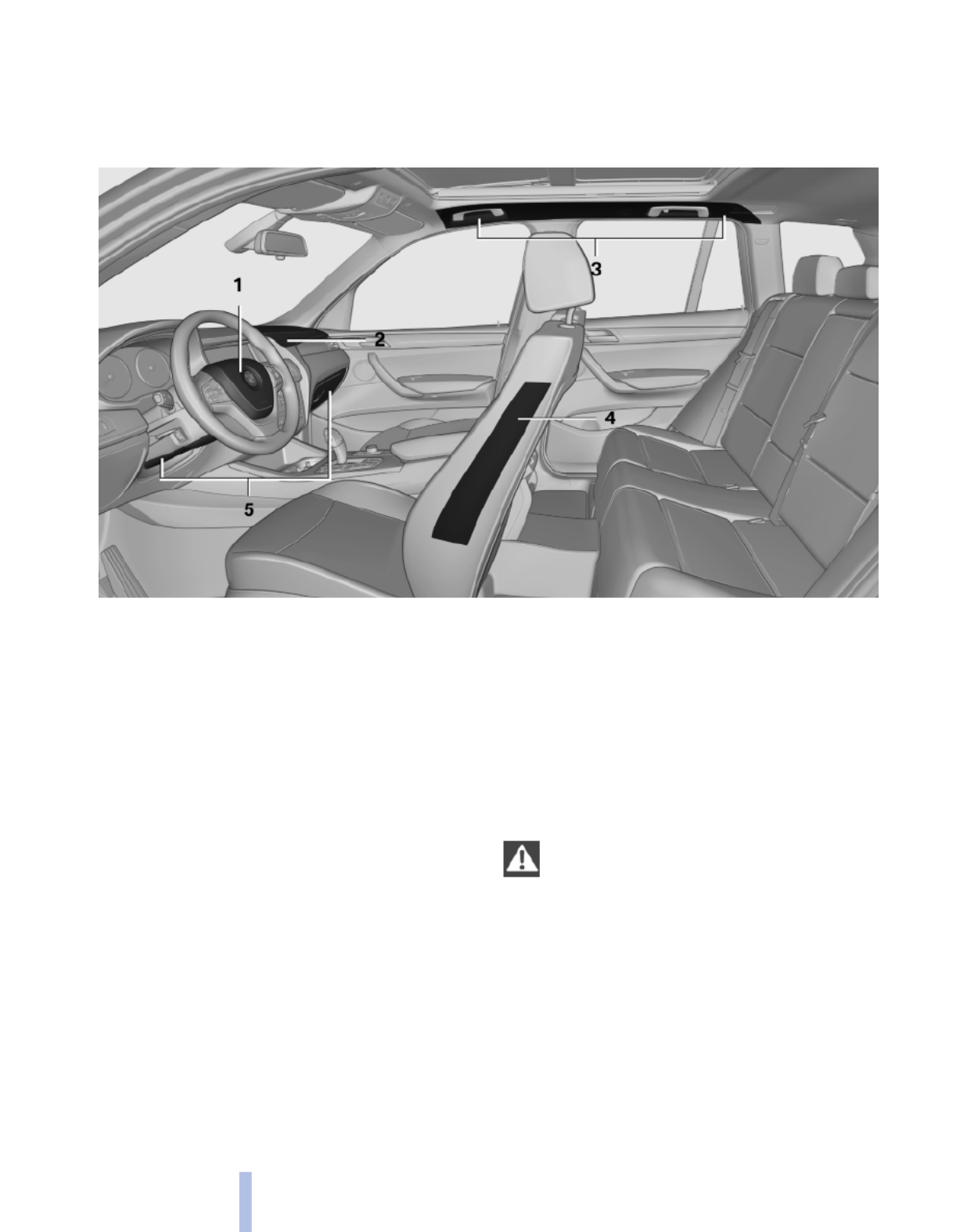
Safety
Airbags
1Front airbag, driver
2Front airbag, front passenger
3Head airbag
4Side airbag
5Knee airbags
Front airbags
Front airbags help protect the driver and front
passenger by responding to frontal impacts in
which safety belts alone cannot provide ade‐
quate restraint.
Side airbags
In a lateral impact, the side airbag supports the
side of the body in the chest and lap area.
Head airbags
In a lateral impact, the head airbag supports the
head.
Knee airbag
The knee airbag supports the legs in a frontal
impact.
Protective action
Airbags are not triggered in every impact situa‐
tion, e.g., in less severe accidents or rear-end
collisions.
Information on how to ensure the optimal
protective effect of the airbags
▷Keep at a distance from the airbags.
▷Always grasp the steering wheel on the
steering wheel rim, holding your hands at
the 3 o'clock and 9 o'clock positions, to keep
the danger of injury to your hands or arms as
low as possible if the airbag is triggered.
▷There should be no people, animals, or ob‐
jects between an airbag and a person.
▷Do not use the cover of the front airbag on
the front passenger side as a storage area.
80
Online Edition for Part no. 01 40 2 606 190 - 12 10 500
Safety

▷Do not place objects under the seat that
could press against the seat from below.
Indicator lamp for the front passenger
airbags
The indicator lamp for the front passenger air‐
bags indicates the operating state of the front
passenger airbags.
The lamp indicates whether the airbags are ac‐
tivated or deactivated.
▷The indicator lamp lights up
when a child who is properly
seated in a child restraint fix‐
ing system intended for that
purpose is detected on the
seat or the seat is empty. The
airbags on the front passen‐
ger side are not activated.
▷The indicator lamp does not light up when,
for example, a correctly seated person of
sufficient size is detected on the seat. The
airbags on the front passenger side are ac‐
tivated.
The system generally detects children seated in
a child seat, especially in the child seats that
were required by NHTSA when the vehicle was
manufactured. After installing a child seat, make
sure that the indicator lamp for the front pas‐
senger airbags lights up. This indicates that the
child seat has been detected and the front pas‐
senger airbags are not activated.
Strength of the driver's and front
passenger airbag
The strength with which the driver's and front
passenger airbags are triggered depends on the
position of the driver's and front passenger
seats.
To maintain the accuracy of this function over
the long-term, calibrate the front seats when a
corresponding message appears on the Control
Display.
Calibrating the front seats
A corresponding message appears on the Con‐
trol Display.
1. Move the respective seat forward all the
way.
2. Move the respective seat forward again. It
moves forward briefly.
3. Readjust the seat to the desired position.
The calibration procedure is completed when
the message on the Control Display disappears.
If the message continues to be displayed, repeat
the calibration.
If the message does not disappear after a repeat
calibration, have the system checked as soon as
possible.
Unobstructed area of movement
Ensure that the area of movement of the
seats is unobstructed to avoid personal injury or
damage to objects.◀
Tire Pressure Monitor TPM*
The concept
The tire inflation pressure is measured in the
four mounted tires. The system notifies you if
there is a significant loss of pressure in one or
more tires.
Functional requirements
The system must have been reset when the in‐
flation pressure was correct; otherwise, reliable
signaling of a flat tire is not ensured. Always use
wheels with TPM electronics to ensure that the
system will operate properly. Reset the system
after each correction of the tire inflation pres‐
sure and after every tire or wheel change.
82
Online Edition for Part no. 01 40 2 606 190 - 12 10 500
Safety

System limits
Sudden tire damage
Sudden serious tire damage caused by
external influences cannot be indicated in ad‐
vance.◀
The system does not operate correctly if it has
not been reset. For example, a flat tire may be
indicated despite correct tire inflation pres‐
sures.
The system is inactive and cannot indicate a flat
tire:
▷For a mounted wheel without TPM electron‐
ics.
▷When the TPM is disturbed by other sys‐
tems or devices with the same radio fre‐
quency.
Status display
The current status of the Tire Pressure Monitor
TPM can be displayed on the Control Display,
e.g., whether or not the TPM is active.
1. "Vehicle Info"
2. "Vehicle status"
3. "Tire Pressure Monitor - TPM"
The status is displayed.
Resetting the system
Reset the system after each correction of the
tire inflation pressure and after every tire or
wheel change.
1. "Vehicle Info"
2. "Vehicle status"
3. "Reset TPM"
4. Start the engine - do not drive away.
5. Reset the tire pressure using "Reset".
6. Drive away.
The tires are shown in gray and "Resetting
TPM..." is displayed.
After driving for a few minutes, the set tire infla‐
tion pressures are applied as set values. The re‐
setting process is completed automatically dur‐
ing driving. The tires are shown in green and
"TPM active" is shown on the Control Display.
The trip can be interrupted at any time. If you
drive away again, the process resumes auto‐
matically.
If a flat tire is detected during a reset, all tires are
displayed in yellow.
Low tire pressure message
The yellow warning lamp lights up. A
Check Control message is displayed.
▷There is a flat tire or a major loss in
tire inflation pressure.
▷The system was not reset after a wheel
change and thus warns based on the infla‐
tion pressures initialized last.
1. Reduce your speed and stop cautiously.
Avoid sudden braking and steering maneu‐
vers.
2. Check whether the vehicle is fitted with reg‐
ular tires* or run-flat tires*.
Run-flat tires, refer to page , are labeled213
with a circular symbol containing the letters
RSC marked on the tire sidewall.
When a low inflation pressure is indicated, DSC
Dynamic Stability Control is switched on if nec‐
essary.
Actions in the event of a flat tire
Normal tires*
1. Identify the damaged tire.
Do this by checking the air pressure in all
four tires.
If the tire inflation pressure in all four tires is
correct, the Tire Pressure Monitor may not
have been initialized. In this case, initialize
the system.
If an identification is not possible, please
contact the service center.
2. Rectify the flat tire on the damaged wheel.
Use of tire sealant, e.g., the Mobility System,
may damage the TPM wheel electronics. In
this case, have the electronics checked at
83
Online Edition for Part no. 01 40 2 606 190 - 12 10 500
Reference Mobility Communication Entertainment Navigation Driving tips Controls At a glance

the next opportunity and have them re‐
placed if necessary.
Run-flat tires*
You can continue driving with a damaged tire at
speeds up to 50 mph/80 km/h.
Do not continue driving without run-flat
tires
Do not continue driving if the vehicle is not
equipped with run-flat tires; continued driving
may result in serious accidents.◀
Continued driving with a flat tire
If continuing to drive with a damaged tire:
1. Avoid sudden braking and steering maneu‐
vers.
2. Do not exceed a speed of 50 mph/80 km/h.
3. Check the air pressure in all four tires at the
next opportunity.
If the tire inflation pressure in all four tires is
correct, the Tire Pressure Monitor may not
have been initialized. In this case, initialize
the system.
Possible driving distance with complete loss of
tire inflation pressure:
The possible driving distance after a loss of tire
inflation pressure depends on the cargo load
and the driving style and conditions.
For a vehicle containing an average load, the
possible driving distance is approx. 50 miles/
80 km.
When the vehicle is driven with a damaged tire,
its handling characteristics change, e.g., re‐
duced lane stability during braking, a longer
braking distance, and altered self-steering
properties. Adjust your driving style accord‐
ingly. Avoid abrupt steering maneuvers or driv‐
ing over obstacles, e.g., curbs, potholes, etc.
Because the possible driving distance depends
on how the vehicle is used during the trip, the
actual distance may be smaller or greater de‐
pending on the driving speed, road conditions,
external temperature, cargo load, etc.
Continued driving with a flat tire
Drive moderately and do not exceed a
speed of 50 mph/80 km/h.
A loss of tire inflation pressure results in a
change in the handling characteristics, e.g., re‐
duced lane stability during braking, a longer
braking distance and altered self-steering prop‐
erties.◀
Final tire failure
Vibrations or loud noises while driving can
indicate the final failure of the tire. Reduce speed
and stop; otherwise, pieces of the tire could
come loose and cause an accident. Do not con‐
tinue driving, and contact your service center.◀
Message when the system was not
reset
A Check Control message is displayed.
The system detected a wheel change
but was not reset.
Warnings regarding the current tire inflation
pressure are not reliable.
Check the tire inflation pressure and reset the
system.
Malfunction
The yellow warning lamp flashes and
then lights up continuously. A Check
Control message is displayed. A flat tire
cannot be detected.
Display in the following situations:
▷A wheel without TPM electronics is fitted:
have the service center check it if necessary.
▷Malfunction: have the system checked by
your service center.
▷TPM could not be fully reset. Reset the sys‐
tem again.
▷Disturbance by systems or devices with the
same radio frequency: after leaving the area
of the disturbance, the system automatically
becomes active again.
Each tire, including the spare (if provided)
should be checked monthly when cold and in‐
flated to the inflation pressure recommended by
84
Online Edition for Part no. 01 40 2 606 190 - 12 10 500
Safety

the vehicle manufacturer on the vehicle placard
or tire inflation pressure label. (If your vehicle has
tires of a different size than the size indicated on
the vehicle placard or tire inflation pressure la‐
bel, you should determine the proper tire infla‐
tion pressure for those tires.) As an added safety
feature, your vehicle has been equipped with a
tire pressure monitoring system (TPMS) that il‐
luminates a low tire pressure telltale when one
or more of your tires is significantly under-in‐
flated. Accordingly, when the low tire pressure
telltale illuminates, you should stop and check
your tires as soon as possible, and inflate them
to the proper pressure. Driving on a significantly
under-inflated tire causes the tire to overheat
and can lead to tire failure. Under-inflation also
reduces fuel efficiency and tire tread life, and
may affect the vehicle's handling and stopping
ability. Please note that the TPMS is not a sub‐
stitute for proper tire maintenance, and it is the
driver's responsibility to maintain correct tire
pressure, even if under-inflation has not reached
the level to trigger illumination of the TPMS low
tire pressure telltale. Your vehicle has also been
equipped with a TPMS malfunction indicator to
indicate when the system is not operating prop‐
erly. The TPMS malfunction indicator is com‐
bined with the low tire pressure telltale. When
the system detects a malfunction, the telltale will
flash for approximately one minute and then re‐
main continuously illuminated. This sequence
will continue upon subsequent vehicle start-ups
as long as the malfunction exists. When the mal‐
function indicator is illuminated, the system may
not be able to detect or signal low tire pressure
as intended. TPMS malfunctions may occur for
a variety of reasons, including the installation of
replacement or alternate tires or wheels on the
vehicle that prevent the TPMS from functioning
properly. Always check the TPMS malfunction
telltale after replacing one or more tires or
wheels on your vehicle to ensure that the re‐
placement or alternate tires and wheels allow
the TPMS to continue to function properly.
Brake force display*
The concept
▷During normal brake application, the outer
brake lamps light up.
▷During heavy brake application, the inner
brake lamps light up in addition.
85
Online Edition for Part no. 01 40 2 606 190 - 12 10 500
Reference Mobility Communication Entertainment Navigation Driving tips Controls At a glance

Driving stability control systems
Antilock Brake System ABS
ABS prevents locking of the wheels during brak‐
ing.
The vehicle remains steerable even during full
brake applications, thus increasing active
safety.
ABS is operational every time you start the en‐
gine.
Brake assistant
When you apply the brakes rapidly, this system
automatically produces the maximum braking
force boost. It thus helps to achieve the shortest
possible braking distance during full braking.
This system utilizes all of the benefits provided
by ABS.
Do not reduce the pressure on the brake pedal
for the duration of the full braking.
DSC Dynamic Stability
Control
The concept
DSC prevents traction loss in the driving wheels
when driving away and accelerating.
DSC also recognizes unstable vehicle condi‐
tions, such as fishtailing or nose-diving. Subject
to physical limits, DSC helps to keep the vehicle
on a steady course by reducing engine speed
and by applying brakes at individual wheels.
Adjust your driving style to the situation
An appropriate driving style is always the
responsibility of the driver.
The laws of physics cannot be repealed, even
with DSC.
Therefore, do not reduce the additional safety
margin by driving in a risky manner.◀
Indicator/warning lamps
The indicator lamp flashes: DSC con‐
trols the drive forces and brake forces.
The indicator lamp lights up: DSC has
failed.
Deactivating DSC: DSC OFF
When DSC is deactivated, driving stability is re‐
duced during acceleration and when driving in
bends.
To increase vehicle stability, activate DSC again
as soon as possible.
Deactivating DSC
Press and hold the button, but not lon‐
ger than approx. 10 seconds, until the
indicator lamp for DSC lights up in the instru‐
ment cluster and DSC OFF is displayed.
The DSC system is switched off.
Activating DSC
Press the button.
DSC OFF and the DSC indicator lamp
go out.
Indicator/warning lamps
When DSC is deactivated, DSC OFF is dis‐
played in the instrument cluster.
The indicator lamp lights up: DSC is de‐
activated.
DTC Dynamic Traction
Control
The concept
The DTC system is a version of the DSC in which
forward momentum is optimized.
86
Online Edition for Part no. 01 40 2 606 190 - 12 10 500
Driving stability control systems

The system ensures maximum forward momen‐
tum on special road conditions, e.g., unplowed
snowy roads, but driving stability is limited.
It is therefore necessary to drive with appropri‐
ate caution.
You may find it useful to briefly activate DTC un‐
der the following special circumstances:
▷When driving in slush or on uncleared,
snow-covered roads.
▷When rocking the vehicle or driving off in
deep snow or on loose surfaces.
▷When driving with snow chains.
Deactivating/activating DTC Dynamic
Traction Control
Activating the Dynamic Traction Control DTC
provides maximum traction on loose ground.
Driving stability is limited during acceleration
and when driving in bends.
Activating DTC
Press the button.
TRACTION is displayed in the instru‐
ment cluster and the indicator lamp for DSC
lights up.
Deactivating DTC
Press the button again.
TRACTION and the DSC indicator lamp
go out.
Performance Control*
Performance Control enhances the agility of
your vehicle.
To enhance performance during sporty driving,
the rear wheel on the inside of the curve is
braked while the resulting braking effect is
largely compensated by engine intervention.
xDrive
xDrive is the all-wheel-drive system of your ve‐
hicle. Concerted action by the xDrive and DSC
further optimize traction and driving dynamics.
The xDrive all-wheel-drive system variably dis‐
tributes the drive forces to the front and rear
axles as demanded by the driving situation and
road surface.
HDC Hill Descent Control
The concept
HDC is a downhill driving assistant that auto‐
matically controls vehicle speed on steep down‐
hill gradients. Without requiring brake applica‐
tion, the vehicle moves at slightly more than
twice walking speed.
You can activate the Hill Descent Control at
speeds below approx. 22 mph/35 km/h. When
driving downhill, the vehicle reduces its speed
to approx. twice walking speed and then keeps
its speed constant.
While you are actively braking, the system is on
standby. The system does not brake the vehicle
during this time.
Use HDC in low gears or in transmission position
D or R only.
Changing the speed
The speed can be changed in the range from
roughly twice walking speed to approx. 15 mph/
25 km/h by lightly pressing the accelerator.
To set the speed: buttons* on the
steering wheel
The desired speed can be specified in the range
from roughly twice walking speed to approx.
15 mph/25 km/h using the rocker switch of the
cruise control on the steering wheel.
87
Online Edition for Part no. 01 40 2 606 190 - 12 10 500
Reference Mobility Communication Entertainment Navigation Driving tips Controls At a glance

▷Press up the rocker switch to the point of
resistance: the speed increases gradually.
▷Press up the rocker switch past the point of
resistance: the speed increases while the
rocker switch is pressed.
▷Press down the rocker switch to the point of
resistance: the speed decreases gradually.
▷Press down the rocker switch past the point
of resistance: when driving forward, the
speed decreases to approx. 6 mph/10 km/h;
when reversing, the speed decreases to ap‐
prox. 4 mph/6 km/h.
Activating HDC
Press the button; the LED above the but‐
ton lights up.
Deactivating HDC
Press the button again and the LED goes
out. HDC is automatically deactivated
above approx. 37 mph/60 km/h.
Display
The selected speed is displayed
in the instrument cluster.
▷Green: the system is actively
braking the vehicle.
▷Orange: the system is on
standby.
Malfunction
A message is displayed in the instrument clus‐
ter. HDC is not available, e.g., due to elevated
brake temperatures.
Dynamic Damping Control*
The concept
This system reduces undesirable vehicle mo‐
tion when using a dynamic driving style or trav‐
eling on uneven road surfaces.
The system enhances driving dynamics and
comfort as required for the road surface and
driving style.
Programs
The system offers two different programs.
The programs can be selected via Dynamic Driv‐
ing Control, refer to page .89
SPORT
Consistently sporty control of the shock absorb‐
ers for greater driving agility.
NORMAL
Balanced control of the vehicle.
Variable sport steering*
The variable sport steering is designed for
sporty driving.
It increases the steering angle of the front
wheels at large steering wheel angles, e.g., in
tight curves or when parking. Steering becomes
more direct.
88
Online Edition for Part no. 01 40 2 606 190 - 12 10 500
Driving stability control systems

It also varies the steering force required to turn
the wheels in accordance with the vehicle
speed.
This results in a sporty steering response. In ad‐
dition, it becomes easier to steer during parking
and maneuvering.
Dynamic Driving Control*
The concept
Dynamic Driving Control can be used to adjust
the driving dynamics of the vehicle. Several pro‐
grams are available for this purpose; they can be
activated using the two Dynamic Driving Control
buttons.
Operating the programs
Press the button Program
DSC OFF
TRACTION
SPORT+
SPORT
NORMAL
Automatic program change
The system automatically switches to NORMAL
in the following situations:
▷Failure of Dynamic Damping Control*.
▷The vehicle has a flat tire.
DSC OFF
When DSC OFF, refer to page 86, is active, driv‐
ing stability is limited during acceleration and
when driving in bends.
TRACTION
When TRACTION is active, the vehicle has max‐
imum traction on loose road surfaces. DTC Dy‐
namic Traction Control, refer to page , is ac‐87
tivated. Driving stability is limited during
acceleration and when driving in bends.
SPORT+
Sporty driving with optimized chassis and sus‐
pension during limited driving stabilization.
Dynamic Traction Control is switched on.
The driver handles several of the stabilization
tasks.
Activating SPORT+
Press the button repeatedly until
SPORT+ appears in the instrument
cluster and the DSC indicator lamp lights up.
Indicator/warning lamps
SPORT+ is displayed in the instrument cluster.
The indicator lamp lights up: DTC Dy‐
namic Traction Control is activated.
SPORT
Consistently sporty tuning of the suspension for
greater driving agility with maximum driving sta‐
bilization.
The program can be configured to individual
specifications.
The configuration is stored for the remote con‐
trol currently in use.
Activating SPORT
Press the button. SPORT+ is displayed
in the instrument cluster.
Configuring SPORT
When the display is activated on the Control
Display, refer to page , the sport program90
can be set to individual specifications.
After the sport program is activated, select
"Configure SPORT mode" on the displayed
panel and configure the program.
Optionally, the sport program can be configured
before it is activated:
1. "Settings"
89
Online Edition for Part no. 01 40 2 606 190 - 12 10 500
Reference Mobility Communication Entertainment Navigation Driving tips Controls At a glance

2. "SPORT mode"
3. Configure the program.
This configuration is retrieved when the sport
program is activated.
NORMAL
For a balanced tuning with maximum driving sta‐
bilization.
Activating NORMAL
Press the button. NORMAL is activated
when the program display disappears
in the instrument cluster.
In certain situations, the system automatically
changes to the NORMAL program, automatic
program change, refer to page .89
Displays
Selected program
The selected program is dis‐
played in the instrument cluster.
Program selection
Pressing the button displays a list
of the selectable programs.
Display on the Control Display
Program changes can be displayed briefly on
the Control Display.
To do so, make the following settings:
1. "Settings"
2. "Control display"
3. "Display driving settings"
90
Online Edition for Part no. 01 40 2 606 190 - 12 10 500
Driving stability control systems

Driving comfort
Cruise control
The concept
The system is functional at speeds beginning at
approx. 20 mph/30 km/h.
It maintains the speed that was set using the
control elements on the steering wheel.
The system brakes on downhill gradients if en‐
gine braking action is insufficient.
Unfavorable conditions
Do not use the system if unfavorable con‐
ditions make it impossible to drive at a constant
speed, for instance:
▷On curvy roads.
▷In heavy traffic.
▷On slippery roads, in fog, snow or rain, or on
a loose road surface.
Otherwise, you could lose control of the vehicle
and cause an accident.◀
Controls
Buttons at a glance
1System on/off, interrupt
2Resume speed
3Store speed
4Store, maintain/change speed
Switching on
Press the button on the steering wheel.
The marking in the speedometer is set to the
current speed.
Cruise control can be used.
Switching off
Deactivated or interrupted system
If the system is deactivated or interrupted,
actively intervene by braking and, if necessary,
with evasive maneuvers; otherwise, there is the
danger of an accident occurring.◀
Press the button.
▷If active: press twice.
▷If interrupted: press once.
The displays go out. The stored desired speed
is deleted.
Interrupting
When active, press the button.
The system is automatically interrupted if:
▷The brakes are applied.
▷Transmission position D is disengaged.
▷DTC Dynamic Traction Control is activated
or DSC is deactivated.
▷DSC is actively controlling stability.
▷HDC is activated.
Maintaining/storing the current speed
Press the button.
91
Online Edition for Part no. 01 40 2 606 190 - 12 10 500
Reference Mobility Communication Entertainment Navigation Driving tips Controls At a glance

Press the rocker switch while the system is in‐
terrupted.
When the system is switched on, the current
speed is maintained and stored as the desired
speed.
It is displayed in the speedometer and briefly
displayed in the instrument cluster, Displays in
the speedometer, refer to page .92
When cruise control is maintained or stored,
DSC Dynamic Stability Control is switched on, if
necessary.
Change, maintain speed
The rocker switch can be pressed while inter‐
rupted to maintain and store the current speed.
Adapting the desired speed
Adapt the desired speed to the road con‐
ditions and be ready to brake at all times; other‐
wise, there is the danger of an accident occur‐
ring.◀
Press the rocker switch up or down repeatedly
until the desired speed is set.
If active, the displayed speed is stored and the
vehicle reaches the stored speed if the road is
clear.
▷Each time the rocker switch is pressed to the
point of resistance, the desired speed in‐
creases or decreases by approx. 1 mph/
1 km/h.
▷Each time the rocker switch is pressed past
the point of resistance, the desired speed
increases or decreases by a maximum of
5 mph/10 km/h.
▷Pressing the rocker switch to the resistance
point and holding it accelerates or deceler‐
ates the vehicle without requiring pressure
on the accelerator. After the rocker switch is
released, the vehicle maintains its final
speed. Pressing the switch beyond the re‐
sistance point causes the vehicle to accel‐
erate more rapidly.
Resuming the desired speed
Press the button.
The stored speed is reached and maintained.
Displays in the instrument cluster
1Display of desired speed
2Indicator lamp
3Brief status display
Desired speed
Display in the speedometer:
▷The marking lights up in
green: the system is active.
▷The marking lights up in or‐
ange: the system has been
interrupted.
▷The marking does not light up: the system is
switched off.
92
Online Edition for Part no. 01 40 2 606 190 - 12 10 500
Driving comfort

▷After approx. 160 ft/50 m when driving for‐
ward.
▷Above approx. 22 mph/36 km/h when driv‐
ing forward.
Switch on the system again if necessary.
Switching on/off manually
Press the button.
▷On: the LED lights up.
▷Off: the LED goes out.
Signal tones
When approaching an object, an intermittent
tone is sounded that indicates the position of the
object. For example, if an object is detected to
the left rear of the vehicle, a signal tone sounds
from the left rear speaker.
The shorter the distance to the object becomes,
the shorter the intervals.
If the distance to a detected object is less than
approx. 12 in/30 cm, a continuous tone is
sounded.
If objects are located both in front of and behind
the vehicle, an alternating continuous signal is
sounded.
The intermittent tone is interrupted after approx.
3 seconds:
▷If the vehicle stops in front of an object that
is detected by only one of the corner sen‐
sors.
▷If moving parallel to a wall.
The signal tone is switched off:
▷When the vehicle moves away from an ob‐
ject by more than approx. 4 in/10 cm.
▷When transmission position P is engaged.
Volume
You can set the volume of the PDC signal tone,
refer to page .147
The setting is stored for the remote control cur‐
rently in use.
Visual warning
The approach of the vehicle to an object can be
shown on the Control Display. Objects that are
farther away are displayed on the Control Dis‐
play before a signal tone sounds.
A display appears as soon as Park Distance
Control (PDC) is activated.
If the backup camera image was selected last, it
again appears on the display. To switch to PDC:
1. "Rear view camera" Select the symbol
on the Control Display.
2. Press the controller.
The setting is stored for the remote control cur‐
rently in use.
Zoom view
On the left part of the display screen, the vehicle
is shown enlarged.
▷Forward gear or transmission position D en‐
gaged: front area of the vehicle.
▷Reverse gear or transmission position R en‐
gaged: rear area of the vehicle.
94
Online Edition for Part no. 01 40 2 606 190 - 12 10 500
Driving comfort

Display on the Control Display
Switching on the backup camera via
iDrive
With PDC activated:
"Rear view camera"
The backup camera image is displayed. The set‐
ting is stored for the remote control currently in
use.
Malfunction
A Check Control message, refer to page , is74
displayed in the instrument cluster.
On the Control Display, the areas in front of and
behind the vehicle are shaded. PDC has failed.
Have the system checked.
To ensure full operability:
▷Keep the sensors clean and free of ice.
▷When using high-pressure washers, do not
spray the sensors for long periods and main‐
tain a distance of at least 12 in/30 cm.
Backup camera*
The concept
The backup camera provides assistance in park‐
ing and maneuvering backwards. The area be‐
hind the vehicle is shown on the Control Display.
System limits
Check the traffic situation as well
Check the traffic situation around the ve‐
hicle with your own eyes. Otherwise, an accident
could result from road users or objects located
outside the picture area of the backup camera.◀
Detection of objects
High, protruding objects such as ledges
may not be detected by the backup camera.◀
Switching on automatically
Select transmission position R with the engine
running.
The backup camera image is displayed if the
system was switched on via the iDrive.
Switching off automatically
The system switches off and the LED goes out:
▷After approx. 33 ft/10 m when driving for‐
ward.
▷Above approx. 9 mph/15 km/h when driving
forward.
Switch on the system again if necessary.
Switching on/off manually
Press the button.
▷On: the LED lights up.
▷Off: the LED goes out.
The PDC is shown on the Control Display.
Switch on the backup camera via the iDrive, refer
to page .97
95
Online Edition for Part no. 01 40 2 606 190 - 12 10 500
Reference Mobility Communication Entertainment Navigation Driving tips Controls At a glance

Assistance functions
Functional requirement
▷The backup camera is switched on.
▷The tailgate is fully closed.
Pathway lines
▷Can be shown in the backup camera image
when in transmission position R.
▷Help you to estimate the space required
when parking and maneuvering on level
roads.
▷Are dependent on the current steering angle
and are continuously adjusted to the steer‐
ing wheel movements.
Show the parking aid lines, refer to page .97
Turning circle lines
▷Can be shown in the backup camera image.
▷Show the course of the smallest possible
turning circle on a level road.
▷Only one turning circle line is displayed
when the steering wheel is turned.
Show the parking aid lines, refer to page .97
Parking using pathway and turning
circle lines
1. Position the vehicle so that the turning circle
lines lead to within the limits of the parking
space.
2. Turn the steering wheel to the point where
the pathway line covers the corresponding
turning circle line.
Obstacle marking
▷Spatially-shaped markings can be shown in
the backup camera image.
Their colored steps match the markings of the
PDC. This simplifies estimation of the distance
to the object shown.
96
Online Edition for Part no. 01 40 2 606 190 - 12 10 500
Driving comfort

Activating the assistance functions
More than one assistance function can be active
at the same time.
Showing the parking aid lines
"Parking aid lines"
Pathway and turning circle lines are displayed.
Showing the obstacle marking
"Obstacle marking"
Spatially-shaped markings are displayed.
Display on the Control Display
Switching on the backup camera via
iDrive
With PDC activated:
"Rear view camera"
The backup camera image is displayed. The set‐
ting is stored for the remote control currently in
use.
Brightness
With the backup camera switched on:
1. Select the symbol.
2. Turn the controller until the desired setting
is reached and press the controller.
Contrast
With the backup camera switched on:
1. Select the symbol.
2. Turn the controller until the desired setting
is reached and press the controller.
Camera
The camera lens is located in the handle of the
tailgate. The image quality may be impaired by
dirt.
Clean the lens, refer to page .235
Top View*
The concept
Top View assists you in parking and maneuver‐
ing. The area around the doors and the road area
around the vehicle are shown on the Control
Display for this purpose.
Capturing the image
The image is captured by two cameras
integrated in the exterior mirrors and by the
backup camera.
The range is approx. 7 ft/2 m to the side and rear.
In this way, obstacles up to the height of the ex‐
terior mirrors are detected early.
System limits
Top View cannot be used in the following situa‐
tions:
▷With a door open.
▷With the tailgate open.
▷With an exterior mirror folded in.
▷In poor light.
A Check Control message is displayed in some
of these situations.
97
Online Edition for Part no. 01 40 2 606 190 - 12 10 500
Reference Mobility Communication Entertainment Navigation Driving tips Controls At a glance

Check the traffic situation as well
Check the traffic situation around the ve‐
hicle with your own eyes. Otherwise, an accident
could result from road users or objects located
outside the picture area of the cameras.◀
Switching on automatically
Select transmission position R with the engine
running.
The Top View and PDC images are displayed if
the system is switched on via iDrive.
Switching off automatically
The system switches off and the LED goes out:
▷After approx. 160 ft/50 m when driving for‐
ward.
▷Above approx. 22 mph/36 km/h when driv‐
ing forward.
Switch on the system again if necessary.
Switching on/off manually
Press the button.
▷On: the LED lights up.
▷Off: the LED goes out.
If Top View is displayed, switch on the backup
camera via the iDrive, refer to page .98
Visual warning
The approach of the vehicle to an object can be
shown on the Control Display.
When the distance to an object is small, a red bar
is shown in front of the vehicle, as it is in the PDC
display.
The display appears as soon as Top View is ac‐
tivated.
If the backup camera image was selected last, it
again appears on the display. To switch to Top
View:
"Rear view camera" Select the symbol on
the Control Display.
The setting is stored for the remote control cur‐
rently in use.
Display on the Control Display
Switching on the backup camera via
iDrive
With Top View switched on:
"Rear view camera"
The backup camera image is displayed. The set‐
ting is stored for the remote control currently in
use.
Brightness
With Top View switched on:
1. "Brightness"
2. Turn the controller until the desired setting
is reached and press the controller.
Contrast
With Top View switched on:
1. "Contrast"
2. Turn the controller until the desired setting
is reached and press the controller.
98
Online Edition for Part no. 01 40 2 606 190 - 12 10 500
Driving comfort

Displaying the turning circle and
pathway lines
▷The static, red turning circle line shows the
space needed to the side of the vehicle
when the steering wheel is turned all the
way.
▷The variable, green pathway line assists you
in assessing the amount of space actually
needed to the side of the vehicle.
The pathway line is dependent on the cur‐
rent steering angle and is continuously ad‐
justed with the steering wheel movement.
"Parking aid lines"
Turning circle and pathway lines are displayed.
Cameras
The objectives of the Top View cameras are lo‐
cated at the bottom of the exterior mirror hous‐
ings. The image quality may be impaired by dirt.
Clean the lens, refer to page .235
Head-up Display*
The concept
This system projects important information into
the driver's field of vision, e.g., the speed.
In this way, the driver can get information with‐
out averting his or her eyes from the road.
Display visibility
The visibility of the displays in the Head-up Dis‐
play is influenced by:
▷Certain sitting positions.
▷Objects on the cover of the Head-up Dis‐
play.
▷Sunglasses with certain polarization filters.
▷Wet roads.
▷Unfavorable light conditions.
If the image is distorted, check the basic set‐
tings.
Switching on/off
1. "Settings"
2. "Head-up display"
3. "Head-up display"
Switch the Head-up Display ON/OFF as re‐
quired.
Display
Selecting displays in the Head-up
Display
1. "Settings"
2. "Head-up display"
3. "Displayed information"
4. Select the desired displays in the Head-up
Display.
The settings are stored for the remote control
currently in use.
Setting the brightness
The brightness is automatically adjusted to the
ambient light.
The basic setting can be adjusted manually.
1. "Settings"
2. "Head-up display"
3. "Brightness"
4. Turn the controller.
99
Online Edition for Part no. 01 40 2 606 190 - 12 10 500
Reference Mobility Communication Entertainment Navigation Driving tips Controls At a glance

The brightness is adjusted.
When the low beams are switched on, the
brightness of the Head-up Display can be addi‐
tionally influenced using the instrument lighting,
refer to page .79
The setting is stored for the remote control cur‐
rently in use.
Adjusting the height
1. "Settings"
2. "Head-up display"
3. "Height"
4. Turn the controller.
The height is adjusted.
The setting is stored for the remote control cur‐
rently in use.
Special windshield
The windshield is part of the system.
The shape of the windshield makes it possible
to display a precise image.
A film in the windshield prevents double images
from being displayed.
Therefore, have the special windshield replaced
by a service center only.
100
Online Edition for Part no. 01 40 2 606 190 - 12 10 500
Driving comfort

Climate control
Automatic climate control
1Vent settings
2Air volume
3AUTO program
4Interior temperature sensor — always keep
clear
5Recirculated-air mode
6Temperature
7Defrosting windows and removing conden‐
sation
8Cooling function
9Rear window defroster
10 Seat heating* 49
Climate control functions in detail
Manual air distribution
Press the buttons repeatedly to select a pro‐
gram:
▷Windows.
▷Upper body region.
▷Footwell.
The programs can be combined as necessary.
Air volume, manual
Turn the wheel to set the desired
air volume.
The higher the rate, the more ef‐
fective the heating or cooling will
be.
The air volume of the automatic climate control
may be reduced automatically to save battery
power.
AUTO program
Press the button.
101
Online Edition for Part no. 01 40 2 606 190 - 12 10 500
Reference Mobility Communication Entertainment Navigation Driving tips Controls At a glance

Air volume, air distribution, and temperature are
controlled automatically.
Depending on the selected temperature and
outside influences, the air is directed to the
windshield, side windows, upper body, and into
the footwell.
The cooling function, refer to page , is102
switched on automatically with the AUTO pro‐
gram.
Recirculated-air mode
You can respond to unpleasant odors or pollu‐
tants in the immediate environment by tempo‐
rarily suspending the supply of outside air. The
system then recirculates the air currently within
the vehicle.
Press the button repeatedly to select
an operating mode:
▷LED off: outside air flows in continuously.
▷LED on, recirculated-air mode: the supply of
outside air into the vehicle is permanently
blocked.
If the windows fog over, switch off recircu‐
lated-air mode and increase the air volume,
if necessary.
Continuous recirculated-air mode
The recirculated-air mode should not be
used for an extended period of time, as the air
quality inside the vehicle deteriorates steadily.◀
Temperature
Turn the wheel to set the desired
temperature.
The automatic climate control achieves this
temperature as quickly as possible, if necessary
with the maximum cooling or heating capacity,
and then keeps it constant.
Avoid rapidly switching between different tem‐
perature settings. The automatic climate control
will not have sufficient time to adjust the set
temperature.
Defrosting windows and removing
condensation
Press the button.
Ice and condensation are quickly re‐
moved from the windshield and the front side
windows.
The air volume can be adjusted when the pro‐
gram is active.
If the windows fog over, also switch on the cool‐
ing function.
Cooling function
The passenger compartment can only be
cooled with the engine running.
Press the button.
The air is cooled and dehumidified and
– depending on the temperature setting –
warmed again.
Depending on the weather, the windshield may
fog up briefly when the engine is started.
The cooling function is switched on automati‐
cally with the AUTO program.
When using the automatic climate control, con‐
densation water, refer to page , develops122
that exits underneath the vehicle.
Rear window defroster
Press the button.
The rear window defroster switches off
automatically after a certain period of time.
Switching the system on/off
Switching off
Turn the rotary switch for the air volume, refer to
page , to 0. The blower and automatic cli‐101
mate control are switched off entirely.
Switching on
Set any air volume.
The AUTO program can also be switched on di‐
rectly via the AUTO button.
102
Online Edition for Part no. 01 40 2 606 190 - 12 10 500
Climate control

Microfilter
The microfilter removes dust and pollen from
the incoming air.
This filter should be replaced during scheduled
maintenance of your vehicle.
More information can be found in the service re‐
quirements display, refer to page .73
Automatic climate control with enhanced features*
1Vent settings
2Temperature, left
3Maximum cooling
4AUTO program
5Air volume, AUTO intensity
6Interior temperature sensor — always keep
clear
7Display
8Automatic recirculated-air control/recircu‐
lated-air mode
9ALL program
10 Temperature, right
11 Defrosting windows and removing conden‐
sation
12 Cooling function
13 Rear window defroster
14 Seat heating* 49
Climate control functions in detail
Manual air distribution
Press the buttons repeatedly to select a pro‐
gram:
▷Windows.
▷Upper body region.
▷Footwell.
103
Online Edition for Part no. 01 40 2 606 190 - 12 10 500
Reference Mobility Communication Entertainment Navigation Driving tips Controls At a glance

The programs can be combined as necessary.
Temperature
Turn the wheel to set the desired
temperature.
The automatic climate control achieves this
temperature as quickly as possible, if necessary
with the maximum cooling or heating capacity,
and then keeps it constant.
Avoid rapidly switching between different tem‐
perature settings. The automatic climate control
will not have sufficient time to adjust the set
temperature.
Maximum cooling
Press the button.
The system is set to the lowest tem‐
perature, maximum air volume and recirculated-
air mode.
Air flows out of the vents for the upper body re‐
gion. Open them for this purpose.
Air is cooled as quickly as possible:
▷At an external temperature of approx. 32 ℉/
0 ℃.
▷When the engine is running.
The air volume can be adjusted when the pro‐
gram is active.
AUTO program
Press the button.
Air volume, air distribution, and tem‐
perature are controlled automatically.
Depending on the selected temperature, AUTO
intensity, and outside influences, the air is di‐
rected to the windshield, side windows, upper
body, and into the footwell.
The cooling function, refer to page , is105
switched on automatically with the AUTO pro‐
gram.
At the same time, a condensation sensor con‐
trols the program so as to prevent window con‐
densation as much as possible.
To switch off the program: press the button
again or manually adjust the air distribution.
Intensity of the AUTO program
With the AUTO program switched on, automatic
control of the air volume and air distribution can
be adjusted.
Press the left or right side of the button:
decrease or increase the intensity.
The selected intensity is shown on the display
of the automatic climate control.
Air volume, manual
To be able to manually adjust the air volume,
switch off the AUTO program first.
Press the left or right side of the button:
decrease or increase air volume.
The selected air volume is shown on the display
of the automatic climate control.
The air volume of the automatic climate control
may be reduced automatically to save battery
power.
Automatic recirculated-air control/
recirculated-air mode
You can respond to unpleasant odors or pollu‐
tants in the immediate environment by tempo‐
rarily suspending the supply of outside air. The
system then recirculates the air currently within
the vehicle.
Press the button repeatedly to select
an operating mode:
▷LEDs off: outside air flows in continuously.
▷Left LED on, automatic recirculated-air con‐
trol: a sensor detects pollutants in the out‐
side air and controls the shut-off automati‐
cally.
▷Right LED on, recirculated-air mode: the
supply of outside air into the vehicle is per‐
manently blocked.
104
Online Edition for Part no. 01 40 2 606 190 - 12 10 500
Climate control
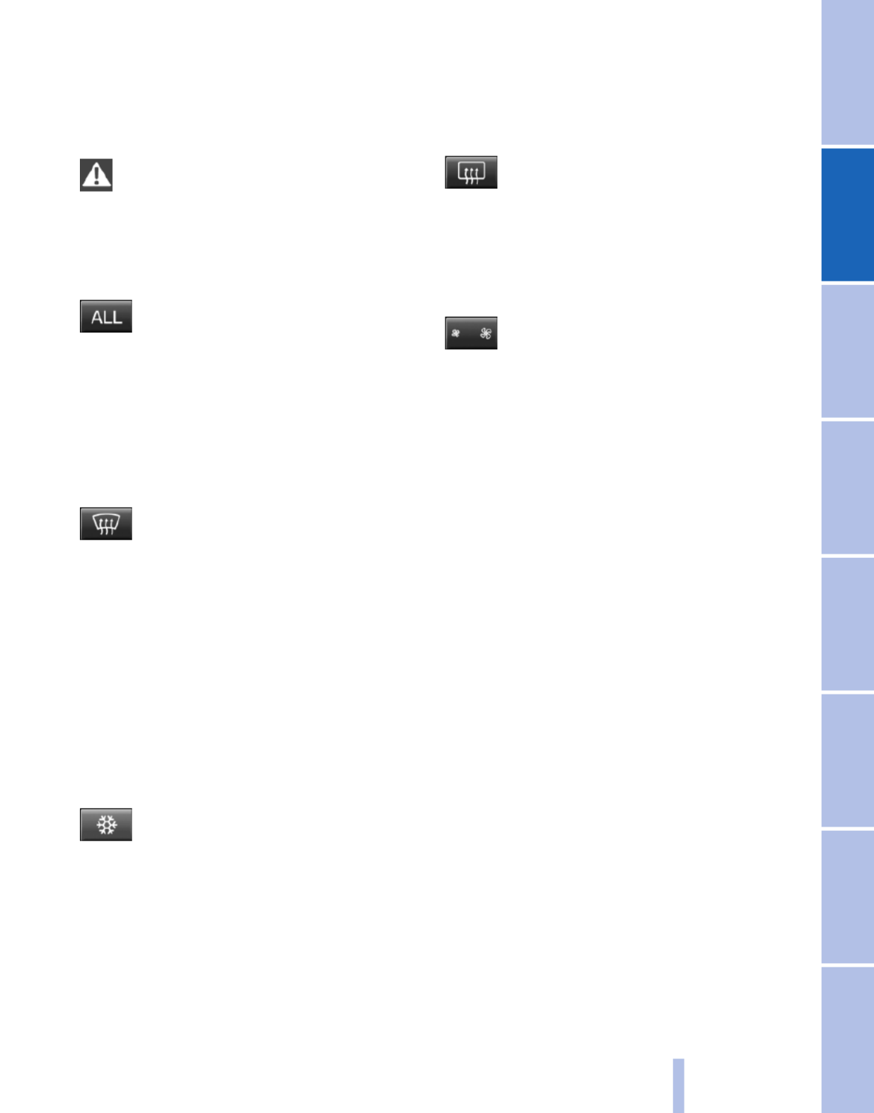
If the windows are fogged over, switch off
the recirculated-air mode and press the
AUTO button to utilize the condensation
sensor. Make sure that air can flow onto the
windshield.
Continuous recirculated-air mode
The recirculated-air mode should not be
used for an extended period of time, as the air
quality inside the vehicle deteriorates steadily.◀
ALL program
Press the button.
The current setting or later settings of
the temperature on the driver's side are trans‐
ferred to the front passenger side.
The program is switched off if the settings on
the front passenger side are changed.
Defrosting windows and removing
condensation
Press the button.
Ice and condensation are quickly re‐
moved from the windshield and the front side
windows.
The air volume can be adjusted when the pro‐
gram is active.
If the windows are fogged over, additionally
switch on the cooling function or press the
AUTO button to utilize the condensation sensor.
Cooling function
The passenger compartment can only be
cooled with the engine running.
Press the button.
The air is cooled and dehumidified and
– depending on the temperature setting –
warmed again.
Depending on the weather, the windshield may
fog up briefly when the engine is started.
The cooling function is switched on automati‐
cally with the AUTO program.
When using the automatic climate control, con‐
densation water, refer to page , develops122
that exits underneath the vehicle.
Rear window defroster
Press the button.
The rear window defroster switches off
automatically after a certain period of time.
Switching the system on/off
Switching off
Press the left button at the minimum
speed.
Switching on
Press any button, except for the buttons for the
ALL program or rear window heating.
Microfilter/activated-charcoal filter,
recirculated-air filter
The microfilter removes dust and pollen from
the incoming air.
The activated-charcoal filter removes gaseous
pollutants from the outside air that enters the
vehicle.
The recirculated-air filter removes dust from the
interior air in recirculated-air mode.
These filters should be replaced during sched‐
uled maintenance of your vehicle.
More information can be found in the service re‐
quirements display, refer to page .73
105
Online Edition for Part no. 01 40 2 606 190 - 12 10 500
Reference Mobility Communication Entertainment Navigation Driving tips Controls At a glance
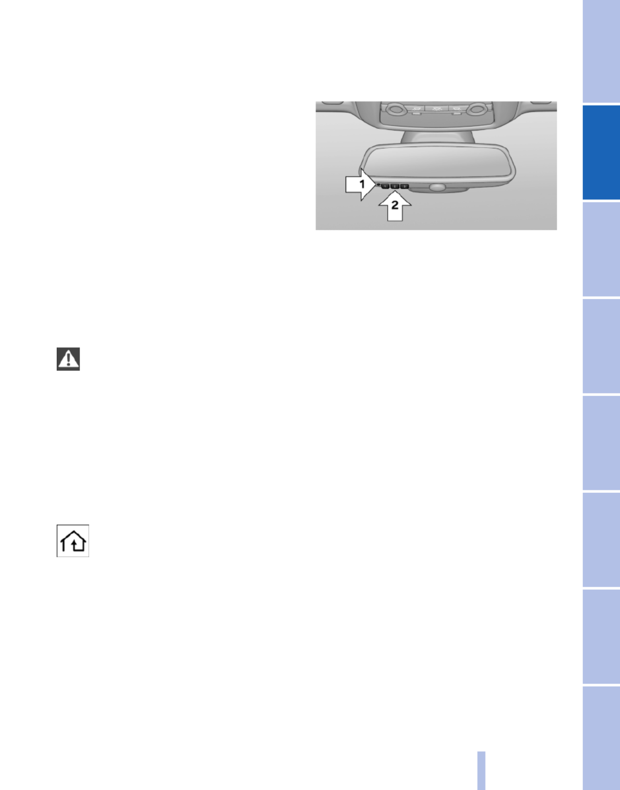
Interior equipment
Integrated universal remote
control*
The concept
This system can replace up to three different
hand-held transmitters for various types of re‐
mote-controlled equipment, such as garage
doors or lighting systems.
The hand-held transmitter signal can be pro‐
grammed on one of the three memory buttons.
The corresponding device can then be operated
using the programmed memory button.
The LED indicates that a signal is being trans‐
mitted.
When selling the vehicle, delete the stored pro‐
grams for security reasons.
During programming
During programming and before activat‐
ing a device using the universal remote control,
ensure that there are no people, animals, or ob‐
jects in the range of movement of the remote-
controlled device; otherwise, there is a risk of
injury or damage.
Also follow the safety instructions of the hand-
held transmitter.◀
Compatibility
If this symbol is printed on the packaging
or in the instructions of the hand-held
transmitter, the remote-controlled de‐
vice is generally compatible with the universal
remote control.
If you have any questions, please contact:
▷Your service center.
▷www.homelink.com on the Internet.
Programming
▷LED, arrow 1.
▷Memory buttons, arrow 2.
Fixed-code hand-held transmitters
1. Switch on the ignition.
2. Initial setup:
Press both outer buttons 1 and 3 for approx.
20 seconds until the LED flashes.
All programs of the three memory buttons,
arrow 2, are cleared.
3. Hold the hand-held transmitter a distance of
approx. 2 to 8 in/5 to 20 cm from the memory
buttons.
4. Simultaneously press the transmit button of
the hand-held transmitter and the memory
button of the universal remote control.
The LED flashes slowly.
5. Release both buttons when the LED flashes
rapidly.
If the LED does not flash rapidly after approx.
15 seconds, change the distance and repeat
the step.
The device can be operated using the memory
button with the engine running or the ignition
switched on.
Malfunction
If the device cannot be used after repeated at‐
tempts at programming, please check whether
the hand-held transmitter is equipped with an
alternating code system.
107
Online Edition for Part no. 01 40 2 606 190 - 12 10 500
Reference Mobility Communication Entertainment Navigation Driving tips Controls At a glance

To do so:
▷Read the instructions of the hand-held
transmitter.
▷Press the memory button of the universal
remote control for an extended period.
If the LED flashes rapidly for a brief period and
then lights up continuously for approx. 2 sec‐
onds, the hand-held transmitter is equipped
with an alternating code system.
In this case, program the memory buttons as
described under Alternating-code hand-held
transmitters.
Alternating-code hand-held
transmitters
Please obtain information on synchronizing the
device in the operating manual of the device be‐
ing set up.
Programming will be easier with the aid of a sec‐
ond person.
1. Park the vehicle within range of the remote-
controlled device.
2. Program the universal remote control as de‐
scribed above under Fixed-code hand-held
transmitters.
3. Press and hold the programmed button on
the interior rearview mirror for approx. 5 sec‐
onds until the device to be adjusted is acti‐
vated.
If the device does not become activated,
press and hold the button and watch the
LED:
▷If the LED lights up continuously, the
programming is completed. The device
should become activated when the but‐
ton is pressed briefly.
▷If the LED flashes for approx. 2 seconds
and then lights up continuously, con‐
tinue the programming procedure be‐
ginning with step 4.
4. Locate the button on the receiver of the de‐
vice to be set, e.g., on the drive.
5. Press the button on the receiver of the de‐
vice to be set. You have approx. 30 seconds
for the next step.
6. Press the programmed memory button of
the universal remote control three times.
The device can be operated when the engine is
running or the ignition is switched on.
Reassigning individual programs
1. Switch on the ignition.
2. Hold the hand-held transmitter a distance of
approx. 2 to 8 in/5 to 20 cm from the memory
buttons.
3. Press the memory button of the universal
remote control.
4. If the LED flashes slowly after approx.
20 seconds, press the transmit button on
the hand-held transmitter.
5. Release both buttons when the LED flashes
rapidly.
If the LED does not flash rapidly after approx.
15 seconds, change the distance and repeat
the step.
Deleting all stored programs
Press the left and right memory buttons for ap‐
prox. 20 seconds until the LED flashes rapidly.
All stored programs are deleted.
The programs cannot be deleted individually.
Lighter*
Danger of burns
Only hold the hot lighter by its head; oth‐
erwise, there is the danger of getting burned.
Switch off the ignition and take the remote con‐
trol with you when leaving the vehicle so that
children cannot use the lighter and burn them‐
selves.◀
108
Online Edition for Part no. 01 40 2 606 190 - 12 10 500
Interior equipment
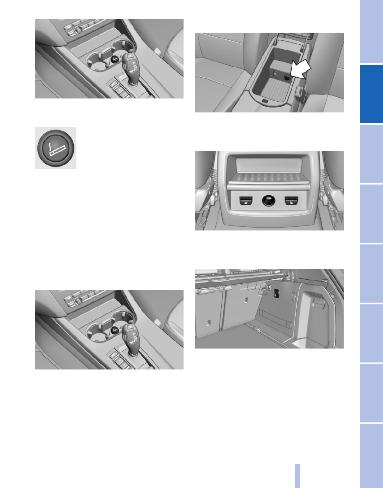
The cigarette lighter is located in the center con‐
sole.
Push in the lighter.
The lighter can be removed as
soon as it pops back out.
Connecting electrical devices
Sockets
The lighter socket can be used for electrical de‐
vices up to approx. 200 watts with 12 volts with
the engine running or the ignition switched on.
Do not damage the socket by using unsuitable
connectors.
Front center console
Remove the cover or cigarette lighter*.
Center armrest
Remove the cover.
Rear center console*
Remove the cover.
In the cargo area
The socket is located on the right side in the
cargo area.
109
Online Edition for Part no. 01 40 2 606 190 - 12 10 500
Reference Mobility Communication Entertainment Navigation Driving tips Controls At a glance

Roof-mounted luggage rack
Note
Roof-mounted luggage racks are only available
for vehicles with roof rails*.
Special rack system as optional
accessory
A special rack system is available as an optional
accessory.
Follow the directions given in the installation in‐
structions.
Anchorage points
The roof rails* provide mounting points for the
roof-mounted luggage rack.
Follow the directions given in the installation in‐
structions.
Mounting
Be sure that adequate clearance is maintained
for raising and opening the glass sunroof*.
Loading
Because roof racks raise the vehicle's center of
gravity when loaded, they have a major effect on
vehicle handling and steering response.
Therefore, note the following when loading and
driving:
▷Do not exceed the approved roof/axle loads
and the approved gross vehicle weight.
▷Distribute the roof load uniformly.
▷The roof load should not be too large in area.
▷Always load the heaviest pieces on the bot‐
tom.
▷Secure the roof luggage firmly, e. g., tie with
ratchet straps.
▷Do not let objects project into the opening
path of the tailgate.
▷Drive smoothly. Avoid sudden acceleration
and braking maneuvers. Take corners gen‐
tly.
Saving fuel
General information
Your vehicle contains advanced technology for
the reduction of fuel consumption and emis‐
sions.
Fuel consumption depends on a number of dif‐
ferent factors.
The implementation of certain measures, driv‐
ing style and regular maintenance, refer to
page , can have an influence on fuel con‐219
sumption and on the environmental impact.
Remove unnecessary cargo
Additional weight increases fuel consumption.
Remove attached parts following use
Remove auxiliary mirrors, roof or rear luggage
racks which are no longer required following
use.
Attached parts on the vehicle impair the aero‐
dynamics and increase the fuel consumption.
Close the windows and glass sunroof*
Driving with the glass sunroof and windows
open results in increased air resistance and
raises fuel consumption.
Check the tire inflation pressure
regularly
Check and, if necessary, correct the tire inflation
pressure, refer to page , at least twice a207
month and before starting on a long trip.
Low tire inflation pressure increases rolling re‐
sistance and thus raises fuel consumption and
tire wear.
Drive away without delay
Do not wait for the engine to warm up while the
vehicle remains stationary. Start driving right
away, but at moderate engine speeds.
This is the fastest way for the cold engine to
reach its operating temperature.
124
Online Edition for Part no. 01 40 2 606 190 - 12 10 500
Things to remember when driving

Navigation*
Navigation system
General information
The navigation system can determine the pre‐
cise position of the vehicle, with the aid of sat‐
ellites and vehicle sensors, and can reliably
guide you to every entered destination.
Navigation data are stored in the vehicle and can
be updated.
Entries in stationary vehicle
Enter data only when the vehicle is sta‐
tionary, and always give priority to the applicable
traffic regulations in the event of any contradic‐
tion between traffic and road conditions and the
instructions issued by the navigation system.
Failure to take to this precaution can place you
in violation of the law and put vehicle occupants
and other road users in danger.◀
Destination input
Manual destination entry
General information
The system supports you in entering street
names and house numbers by automatically
completing the entry and providing entry com‐
parisons, refer to page .24
Stored town/city and street names can be called
up quickly.
▷If the existing entries should not be changed,
the entries for the state/province and town/
city can be skipped.
▷Destination guidance is started to the town/
city center if no street is entered.
Entering a state/province
1. Press the MENU button.
2. "Navigation"
3. "Enter address"
4. Select "State/Province" or the displayed
state/province.
Entering a town/city
1. Select "Town/City/Postal Code" or the dis‐
played town/city.
2. Select letters, if necessary.
The list is narrowed down further with each
entry.
3. Move the controller to the right.
4. Select the town/city name from the list.
If there are several towns/cities with the same
name:
1. Change to the list of town/city names.
2. Highlight the town/city.
3. Select the town/city.
Entering the postal code
1. Select "Town/City/Postal Code" or the dis‐
played town/city.
2. Select the symbol.
128
Online Edition for Part no. 01 40 2 606 190 - 12 10 500
Navigation

▷To change the scale: turn the controller.
▷To shift the map: move the controller in
the required direction.
▷To shift the map diagonally: move the
controller in the required direction and
turn it.
Specifying the street
If the system does not recognize a street, one of
the following is displayed:
▷The name of a street in the vicinity.
▷The county.
▷The coordinates of the destination.
Additional functions
Additional functions are available on the inter‐
active map after the controller is pressed.
▷ Select the symbol.
"Start guidance" or "Add as another
destination"
Add a destination as a further destination,
refer to page .134
▷"Exit interactive map": return to the map
view.
▷"View in northern direction"
▷"Display destination": the map section
around the destination is displayed.
▷"Display current location": the map section
around your current location is displayed.
▷"Find points of interest": the search for spe‐
cial destinations is started.
Destination entry by voice*
General information
▷Instructions for voice activation system, re‐
fer to page .25
▷When making a destination entry by voice,
you can change between voice operation
and iDrive.
▷To have the available spoken instructions
read out loud: ›Voice commands‹
Saying the entries
▷the town/city, street, and house number can
be entered as a single command*.
▷Countries, towns and cities, streets, and in‐
tersections can be said as whole words* or
spelled in the language of the system, refer
to page .73
Example: to enter a town/city in a US state
as a whole word, the language of the system
must be English.
▷Spell the entry if the spoken language and
the language of the system differ.
▷Say the letters smoothly, and avoid exag‐
gerating the pronunciation and inserting
lengthy pauses between the letters.
▷The options available for entering data de‐
pend on the navigation data and the country
and language settings.
entering an address using a command*
1. Press the button on the steering
wheel.
2. ›Enter address‹
3. Wait for a request from the system.
4. Say the address in the suggested order.
5. Continue making the entry as prompted by
the system.
If necessary, individually name the separate
components of the address, e.g., the town/city.
133
Online Edition for Part no. 01 40 2 606 190 - 12 10 500
Reference Mobility Communication Entertainment Navigation Driving tips Controls At a glance

produce, duplicate, republish, transmit or
distribute in any way any portion of traffic in‐
cident data. You agree to indemnify, defend
and hold harmless BMW of North America,
LLC. (“BMW NA”) and Total Traffic Net‐
work, Inrix, Inc (and their affiliates) against
any and all claims, damages, costs or other
expenses that arise directly or indirectly out
of (a) your unauthorized use of the traffic in‐
cident data or the RDS-TMC network, (b)
your violation of this directive and/or (c) any
unauthorized or unlawful activities by you in
connection herewith.
B. Total Traffic Network traffic data is infor‐
mational only. User assumes all risk of use.
Total Traffic Network, BMW NA, and their
suppliers make no representations about
content, traffic and road conditions, route
usability, or speed.
C. The licensed material is provided to li‐
censee “as is,” and “where is”. Total Traffic
Network, including, but not limited to, any
and all third party providers of any of the li‐
censed material, expressly disclaims, to the
fullest extent permitted by law, all warranties
or representations with respect to the li‐
censed material (including, without limita‐
tion, that the licensed material will be error-
free, will operate without interruption or that
the traffic data will be accurate), express, im‐
plied or statutory, including, without limita‐
tion, the implied warranties of merchanta‐
bility, non-infringement fitness for a
particular purpose, or those arising from a
course of dealing or usage of trade.
D. Neither Total Traffic Network, Inrix, Inc. or
BMW NA will be liable to you for any indirect,
special, consequential, exemplary, or inci‐
dental damages (including, without limita‐
tion, lost revenues, anticipated revenues, or
profits relating to the same) arising from any
claim relating directly or indirectly to use of
the traffic data, and even if Total Traffic Net‐
work, Inrix, Inc., or BMW NA are aware of the
possibility of such damages. These limita‐
tions apply to all claims, including, without
limitation, claims in contract and tort (such
as negligence, product liability and strict li‐
ability). Some states do not allow the exclu‐
sion or limitation of incidental or consequen‐
tial damages, so those particular limitations
may not apply to you.
▷The traffic bulletins are indicated on the map
by symbols.
▷The traffic bulletins for the surrounding area
are stored in a list.
The symbol in the function bar of the map
view turns red if there are traffic bulletins
that affect the calculated route.
Switching the reception on/off
1. "Navigation"
2. Open "Options".
3. "Receive Traffic Info"
Open the traffic bulletins
1. "Navigation"
2. "Map"
3. "Traffic Info"
First the traffic bulletins for the calculated
route are displayed.
The traffic bulletins are sorted by their dis‐
tance from the current position of the vehi‐
cle.
4. Select a traffic bulletin.
"More information": display additional
information.
5. Scroll to the next or previous traffic bulletin
if required.
Traffic bulletins on the map
When the traffic situation/gray card is activated,
the view on the Control Display is switched over
to shades of gray. This enables a better view of
the traffic bulletins. The day/night mode is dis‐
regarded in this setting. Symbols and special
destinations are not displayed.
1. "Navigation"
2. "Map"
3. Open "Options".
140
Online Edition for Part no. 01 40 2 606 190 - 12 10 500
Navigation

3. "Additional options"
4. "Zoom mode"
Selecting a track
DVD video:
1. Turn the controller when the DVD menu is
displayed.
2. Open "Options".
3. "Additional options"
4. "Select title"
5. Select the desired track.
VCD/SVCD:
1. "Select track"
2. Select the desired track.
Selecting the camera angle*
The availability of a different camera angle de‐
pends on the DVD and the current DVD track.
1. Turn the controller during playback.
2. Open "Options".
3. "Additional options"
4. "Viewing angle"
5. Select the desired camera angle.
Opening the main menu, back
These functions are not contained on every
DVD. Therefore, they may not be available for
use.
DVD changer*
In the cargo area
The DVD changer is stored behind the left side
trim in the cargo area.
Controls and displays
1Empty DVD compartments
2LED on DVD slot
3Buttons for DVD compartments
4DVD slot
5Fill DVD compartments
Filling the DVD compartments
individually
1. Press the button.
The LED on the first empty compartment
flashes.
2. Select another compartment if necessary.
3. Wait for the LEDs on the DVD slot to flash.
4. Insert a single CD or DVD in the middle.
The CD/DVD is drawn in automatically and
placed into the selected compartment.
159
Online Edition for Part no. 01 40 2 606 190 - 12 10 500
Reference Mobility Communication Entertainment Navigation Driving tips Controls At a glance

Communication
All of the options available to you for mobile
communication with family, friends, business
partners, and service providers are described in
this chapter.
Online Edition for Part no. 01 40 2 606 190 - 12 10 500
Product specificaties
| Merk: | BMW |
| Categorie: | Auto |
| Model: | X3 xDrive35i (2011) |
Heb je hulp nodig?
Als je hulp nodig hebt met BMW X3 xDrive35i (2011) stel dan hieronder een vraag en andere gebruikers zullen je antwoorden
Handleiding Auto BMW

25 Juni 2023
21 Juni 2023
19 Juni 2023
10 Juni 2023
30 Mei 2023
27 Mei 2023
24 Mei 2023
21 Mei 2023
14 Mei 2023
13 Mei 2023
Handleiding Auto
- Auto Ford
- Auto Fiat
- Auto Opel
- Auto Pioneer
- Auto Renault
- Auto Volvo
- Auto ACME
- Auto Alfa Romeo
- Auto Audi
- Auto Audio-Technica
- Auto Dacia
- Auto Dodge
- Auto DS
- Auto Honda
- Auto Hyundai
- Auto Infiniti
- Auto Kia
- Auto Lancia
- Auto Land Rover
- Auto Lexus
- Auto Marklin
- Auto Maserati
- Auto Mazda
- Auto Mercedes-Benz
- Auto Mercury
- Auto Mini
- Auto Mitsubishi
- Auto Nissan
- Auto Peugeot
- Auto POLARIS
- Auto Porsche
- Auto Saab
- Auto Saturn
- Auto Seat
- Auto Sharper Image
- Auto Skoda
- Auto Smart
- Auto Subaru
- Auto Suzuki
- Auto Tesla
- Auto Toyota
- Auto Vauxhall
- Auto Volkswagen
- Auto Jaguar
- Auto Jeep
- Auto Abarth
- Auto Acura
- Auto Aston Martin
- Auto Buick
- Auto Cadillac
- Auto Chevrolet
- Auto Chrysler
- Auto Citroën
- Auto Genesis
- Auto GMC
- Auto Lincoln
- Auto Mahindra
- Auto MG
- Auto Polestar
- Auto Pontiac
- Auto Rover
- Auto Scion
- Auto Tata
- Auto VDL
- Auto RAM
- Auto GEM
- Auto Aguilar
- Auto Chery
- Auto Lada
- Auto McLaren
Nieuwste handleidingen voor Auto

25 Maart 2025

13 Maart 2025

10 Maart 2025
10 Maart 2025
9 Maart 2025
9 Maart 2025
9 Maart 2025

4 Maart 2025
4 Maart 2025
3 Maart 2025