ATen VK248 Handleiding
ATen
Niet gecategoriseerd
VK248
Lees hieronder de 📖 handleiding in het Nederlandse voor ATen VK248 (269 pagina's) in de categorie Niet gecategoriseerd. Deze handleiding was nuttig voor 39 personen en werd door 2 gebruikers gemiddeld met 4.5 sterren beoordeeld
Pagina 1/269

ATEN Control System
User Manual
www.aten.com
ATEN Control System User Manual
ii
EMC Information
FEDERAL COMMUNICATIONS COMMISSION INTERFERENCE
STATEMENT
This equipment has been tested and found to comply with the limits for a Class A digital
device, pursuant to Part 15 of the FCC Rules. These limits are designed to provide
reasonable protection against harmful interference when the equipment is operated in a
commercial environment. This equipment generates, uses, and can radiate radio
frequency energy and, if not installed and used in accordance with the instruction
manual, may cause harmful interference to radio communications. Operation of this
equipment in a residential area is likely to cause harmful interference in which case the
user will be required to correct the interference at his own expense.
FCC Caution: Any changes or modifications not expressly approved by the party
responsible for compliance could void the user's authority to operate this equipment.
Warning: Operation of this equipment in a residential environment could cause radio
interference.
KCC Statement
RoHS
This product is RoHS compliant.
Safety
This product has been classified as Information Technology Equipment.

ATEN Control System User Manual
iii
User Information
Online Registration
Be sure to register your product at our online support center:
Telephone Support
For telephone support, call this number:
User Notice
All information, documentation, and specifications contained in this manual
are subject to change without prior notification by the manufacturer. The
manufacturer makes no representations or warranties, either expressed or
implied, with respect to the contents hereof and specifically disclaims any
warranties as to merchantability or fitness for any particular purpose. Any of
the manufacturer's software described in this manual is sold or licensed as is.
Should the programs prove defective following their purchase, the buyer (and
not the manufacturer, its distributor, or its dealer), assumes the entire cost of all
necessary servicing, repair and any incidental or consequential damages
resulting from any defect in the software.
The manufacturer of this system is not responsible for any radio and/or TV
interference caused by unauthorized modifications to this device. It is the
responsibility of the user to correct such interference.
The manufacturer is not responsible for any damage incurred in the operation
of this system if the correct operational voltage setting was not selected prior
to operation. PLEASE VERIFY THAT THE VOLTAGE SETTING IS
CORRECT BEFORE USE.
International http://eservice.aten.com
International 886-2-8692-6959
China 86-400-810-0-810
Japan 81-3-5615-5811
Korea 82-2-467-6789
North America 1-888-999-ATEN ext 4988
1-949-428-1111

ATEN Control System User Manual
iv
Package Contents
VK0100
The VK0100 package consists of:
1 VK0100 8-Button Control Pad (US, 1 Gang)
1 Button Pack
6 Terminal Blocks
1 Faceplate
1 User Instructions*
VK0200
The VK0200 package consists of:
1 VK0200 12-Button Control Pad (EU, 2 Gang)
1 Button Pack
6 Terminal Blocks
1 Faceplate
1 User Instructions*
VK1100
The VK1100 package consists of:
1 VK1100 Compact Control Box
4 Terminal Blocks
1 Power Cord
1 User Instructions*
VK2100
The VK2100 package consists of:
1 VK2100 Control Box
1 Rack Mount Kit
9 Terminal Blocks
1 Power Cord
1 User Instructions*

ATEN Control System User Manual
v
Note:
Read this manual thoroughly and follow the installation and operation
procedures carefully to prevent any damage to the ATEN controller and
other connected devices.
The product firmware may have been updated with new features after the
release of this manual. For an up-to-date user manual, visit:
http://www.aten.com/global/en/

ATEN Control System User Manual
vi
Contents
EMC Information. . . . . . . . . . . . . . . . . . . . . . . . . . . . . . . . . . . . . . . . . . . . . ii
Safety . . . . . . . . . . . . . . . . . . . . . . . . . . . . . . . . . . . . . . . . . . . . . . . . . . . . . ii
User Information . . . . . . . . . . . . . . . . . . . . . . . . . . . . . . . . . . . . . . . . . . . . iii
Online Registration . . . . . . . . . . . . . . . . . . . . . . . . . . . . . . . . . . . . . . . .iii
Telephone Support . . . . . . . . . . . . . . . . . . . . . . . . . . . . . . . . . . . . . . . .iii
Package Contents . . . . . . . . . . . . . . . . . . . . . . . . . . . . . . . . . . . . . . . . . . .iv
VK0100 . . . . . . . . . . . . . . . . . . . . . . . . . . . . . . . . . . . . . . . . . . . . . . . . .iv
VK0200 . . . . . . . . . . . . . . . . . . . . . . . . . . . . . . . . . . . . . . . . . . . . . . . . .iv
VK1100 . . . . . . . . . . . . . . . . . . . . . . . . . . . . . . . . . . . . . . . . . . . . . . . . .iv
VK2100 . . . . . . . . . . . . . . . . . . . . . . . . . . . . . . . . . . . . . . . . . . . . . . . . .iv
Contents . . . . . . . . . . . . . . . . . . . . . . . . . . . . . . . . . . . . . . . . . . . . . . . . . .vi
About this Manual . . . . . . . . . . . . . . . . . . . . . . . . . . . . . . . . . . . . . . . . . . .xi
Conventions . . . . . . . . . . . . . . . . . . . . . . . . . . . . . . . . . . . . . . . . . . . . . . . xii
Terminology . . . . . . . . . . . . . . . . . . . . . . . . . . . . . . . . . . . . . . . . . . . . . . xiii
Product Information . . . . . . . . . . . . . . . . . . . . . . . . . . . . . . . . . . . . . . . . . xiii
1. Introduction
Overview. . . . . . . . . . . . . . . . . . . . . . . . . . . . . . . . . . . . . . . . . . . . . . . . . . . 1
Benefits . . . . . . . . . . . . . . . . . . . . . . . . . . . . . . . . . . . . . . . . . . . . . . . . . . . 3
Intelligent Control . . . . . . . . . . . . . . . . . . . . . . . . . . . . . . . . . . . . . . . . . 3
Features . . . . . . . . . . . . . . . . . . . . . . . . . . . . . . . . . . . . . . . . . . . . . . . . . . . 5
ATEN Control Box . . . . . . . . . . . . . . . . . . . . . . . . . . . . . . . . . . . . . . . . 5
ATEN Control Pad . . . . . . . . . . . . . . . . . . . . . . . . . . . . . . . . . . . . . . . . 6
ATEN Configurator . . . . . . . . . . . . . . . . . . . . . . . . . . . . . . . . . . . . . . . . 7
ATEN Control System App . . . . . . . . . . . . . . . . . . . . . . . . . . . . . . . . . . 7
ATEN Keypads . . . . . . . . . . . . . . . . . . . . . . . . . . . . . . . . . . . . . . . . . . . 8
Requirements . . . . . . . . . . . . . . . . . . . . . . . . . . . . . . . . . . . . . . . . . . . . . . 9
Accessories . . . . . . . . . . . . . . . . . . . . . . . . . . . . . . . . . . . . . . . . . . . . . . . 10
2. Hardware Setup
ATEN Control Box . . . . . . . . . . . . . . . . . . . . . . . . . . . . . . . . . . . . . . . . . . 11
Panel Components . . . . . . . . . . . . . . . . . . . . . . . . . . . . . . . . . . . . . . . 11
VK2100 Front View . . . . . . . . . . . . . . . . . . . . . . . . . . . . . . . . . . . 11
VK2100 Rear View . . . . . . . . . . . . . . . . . . . . . . . . . . . . . . . . . . . . 13
VK1100 Front View . . . . . . . . . . . . . . . . . . . . . . . . . . . . . . . . . . . 14
VK1100 Rear View . . . . . . . . . . . . . . . . . . . . . . . . . . . . . . . . . . . . 16
Rack Mounting the ATEN Control Box . . . . . . . . . . . . . . . . . . . . . . . . 17
VK2100 . . . . . . . . . . . . . . . . . . . . . . . . . . . . . . . . . . . . . . . . . . . . . 17
VK1100 . . . . . . . . . . . . . . . . . . . . . . . . . . . . . . . . . . . . . . . . . . . . . 18
Control Box Connections . . . . . . . . . . . . . . . . . . . . . . . . . . . . . . . . . . 19
12VDC Power Output . . . . . . . . . . . . . . . . . . . . . . . . . . . . . . . . . . . . . 23
Relay . . . . . . . . . . . . . . . . . . . . . . . . . . . . . . . . . . . . . . . . . . . . . . . . . 27
IR / Serial . . . . . . . . . . . . . . . . . . . . . . . . . . . . . . . . . . . . . . . . . . . . . . 28

ATEN Control System User Manual
vii
One IR Transmitter . . . . . . . . . . . . . . . . . . . . . . . . . . . . . . . . . . . . 29
Two IR Transmitters . . . . . . . . . . . . . . . . . . . . . . . . . . . . . . . . . . . 29
Digital I/O . . . . . . . . . . . . . . . . . . . . . . . . . . . . . . . . . . . . . . . . . . . . . . 30
RS-232 . . . . . . . . . . . . . . . . . . . . . . . . . . . . . . . . . . . . . . . . . . . . . . . .32
RS-232 / 422 / 485 . . . . . . . . . . . . . . . . . . . . . . . . . . . . . . . . . . . . . . .33
Ethernet . . . . . . . . . . . . . . . . . . . . . . . . . . . . . . . . . . . . . . . . . . . . . . .34
ATEN Control Pad. . . . . . . . . . . . . . . . . . . . . . . . . . . . . . . . . . . . . . . . . . .35
Panel Components . . . . . . . . . . . . . . . . . . . . . . . . . . . . . . . . . . . . . . . 35
Installing the Control Pads . . . . . . . . . . . . . . . . . . . . . . . . . . . . . . . . . 37
Installation Steps . . . . . . . . . . . . . . . . . . . . . . . . . . . . . . . . . . . . . . 37
RS-232 Serial Connection . . . . . . . . . . . . . . . . . . . . . . . . . . . . . . 42
Relay Connections . . . . . . . . . . . . . . . . . . . . . . . . . . . . . . . . . . . .43
Digital Input Device . . . . . . . . . . . . . . . . . . . . . . . . . . . . . . . . . . . . 44
Ethernet . . . . . . . . . . . . . . . . . . . . . . . . . . . . . . . . . . . . . . . . . . . . 45
Accessories . . . . . . . . . . . . . . . . . . . . . . . . . . . . . . . . . . . . . . . . . . . . . . . 46
ATEN Expansion Box . . . . . . . . . . . . . . . . . . . . . . . . . . . . . . . . . . . . . 46
ATEN Keypad . . . . . . . . . . . . . . . . . . . . . . . . . . . . . . . . . . . . . . . . . . . 47
Overview . . . . . . . . . . . . . . . . . . . . . . . . . . . . . . . . . . . . . . . . . . . .47
Component . . . . . . . . . . . . . . . . . . . . . . . . . . . . . . . . . . . . . . . . . .48
Layout Examples . . . . . . . . . . . . . . . . . . . . . . . . . . . . . . . . . . . . . .49
Installing ATEN Keypad. . . . . . . . . . . . . . . . . . . . . . . . . . . . . . . . . 50
3. Browser Operation
Overview . . . . . . . . . . . . . . . . . . . . . . . . . . . . . . . . . . . . . . . . . . . . . . . . . . 55
Logging In . . . . . . . . . . . . . . . . . . . . . . . . . . . . . . . . . . . . . . . . . . . . . . . . .55
Dashboard . . . . . . . . . . . . . . . . . . . . . . . . . . . . . . . . . . . . . . . . . . . . . . . .56
Settings . . . . . . . . . . . . . . . . . . . . . . . . . . . . . . . . . . . . . . . . . . . . . . . . . . 57
Licenses for Mobile Control . . . . . . . . . . . . . . . . . . . . . . . . . . . . . . . . 59
Storage . . . . . . . . . . . . . . . . . . . . . . . . . . . . . . . . . . . . . . . . . . . . . . . . 60
Access . . . . . . . . . . . . . . . . . . . . . . . . . . . . . . . . . . . . . . . . . . . . . . . .61
Monitor . . . . . . . . . . . . . . . . . . . . . . . . . . . . . . . . . . . . . . . . . . . . . . . . 63
Network . . . . . . . . . . . . . . . . . . . . . . . . . . . . . . . . . . . . . . . . . . . . . . . .64
Connections . . . . . . . . . . . . . . . . . . . . . . . . . . . . . . . . . . . . . . . . . . . . 65
Schedule . . . . . . . . . . . . . . . . . . . . . . . . . . . . . . . . . . . . . . . . . . . . . . . 66
Security . . . . . . . . . . . . . . . . . . . . . . . . . . . . . . . . . . . . . . . . . . . . . . . 67
4. ATEN Configurator (VK6000)
Overview . . . . . . . . . . . . . . . . . . . . . . . . . . . . . . . . . . . . . . . . . . . . . . . . . . 69
Installation. . . . . . . . . . . . . . . . . . . . . . . . . . . . . . . . . . . . . . . . . . . . . . . . . 69
Getting Started Tasks . . . . . . . . . . . . . . . . . . . . . . . . . . . . . . . . . . . . . . . . 72
Main Page . . . . . . . . . . . . . . . . . . . . . . . . . . . . . . . . . . . . . . . . . . . . . . . .74
Menu Bar . . . . . . . . . . . . . . . . . . . . . . . . . . . . . . . . . . . . . . . . . . . . . . . . .76
Project . . . . . . . . . . . . . . . . . . . . . . . . . . . . . . . . . . . . . . . . . . . . . . . . . . . 82
Device . . . . . . . . . . . . . . . . . . . . . . . . . . . . . . . . . . . . . . . . . . . . . . . . . . . 84
Device Configuration List . . . . . . . . . . . . . . . . . . . . . . . . . . . . . . . . . . 85
Adding Devices to ATEN Configurator . . . . . . . . . . . . . . . . . . . . . 86

ATEN Control System User Manual
viii
Left Sidebar . . . . . . . . . . . . . . . . . . . . . . . . . . . . . . . . . . . . . . . . . . . . 88
Properties . . . . . . . . . . . . . . . . . . . . . . . . . . . . . . . . . . . . . . . . . . . . . . 89
Controller Properties . . . . . . . . . . . . . . . . . . . . . . . . . . . . . . . . . . 89
Expansion Box (Expander) . . . . . . . . . . . . . . . . . . . . . . . . . . . . . . 91
Serial Device Properties . . . . . . . . . . . . . . . . . . . . . . . . . . . . . . . . 92
I/O Device Properties . . . . . . . . . . . . . . . . . . . . . . . . . . . . . . . . . . 94
IR/Relay Device Properties . . . . . . . . . . . . . . . . . . . . . . . . . . . . . 95
Ethernet Device Properties . . . . . . . . . . . . . . . . . . . . . . . . . . . . . 96
Library . . . . . . . . . . . . . . . . . . . . . . . . . . . . . . . . . . . . . . . . . . . . . . . . 98
Device Library . . . . . . . . . . . . . . . . . . . . . . . . . . . . . . . . . . . . . . . . . . 99
Design . . . . . . . . . . . . . . . . . . . . . . . . . . . . . . . . . . . . . . . . . . . . . . . . . . 100
Overview . . . . . . . . . . . . . . . . . . . . . . . . . . . . . . . . . . . . . . . . . . . . . 100
Left Sidebar . . . . . . . . . . . . . . . . . . . . . . . . . . . . . . . . . . . . . . . . . . . 101
Viewer . . . . . . . . . . . . . . . . . . . . . . . . . . . . . . . . . . . . . . . . . . . . 101
Pages . . . . . . . . . . . . . . . . . . . . . . . . . . . . . . . . . . . . . . . . . . . . . 101
Adding a Viewer . . . . . . . . . . . . . . . . . . . . . . . . . . . . . . . . . . . . . . . . 102
Configuring the Viewer . . . . . . . . . . . . . . . . . . . . . . . . . . . . . . . . . . . 106
Object Properties . . . . . . . . . . . . . . . . . . . . . . . . . . . . . . . . . . . . . . . . . . 109
Page Objects . . . . . . . . . . . . . . . . . . . . . . . . . . . . . . . . . . . . . . . . . . 109
Object Properties for Mobile Devices . . . . . . . . . . . . . . . . . . . . . . . . 110
Buttons . . . . . . . . . . . . . . . . . . . . . . . . . . . . . . . . . . . . . . . . . . . . 110
Groups . . . . . . . . . . . . . . . . . . . . . . . . . . . . . . . . . . . . . . . . . . . . 114
Labels . . . . . . . . . . . . . . . . . . . . . . . . . . . . . . . . . . . . . . . . . . . . . 115
Slider Bars . . . . . . . . . . . . . . . . . . . . . . . . . . . . . . . . . . . . . . . . . 116
PowerPoint Control and Media Control Templates . . . . . . . . . . . 118
Image . . . . . . . . . . . . . . . . . . . . . . . . . . . . . . . . . . . . . . . . . . . . . 119
Layering Images . . . . . . . . . . . . . . . . . . . . . . . . . . . . . . . . . . . . . 120
Dial Kit . . . . . . . . . . . . . . . . . . . . . . . . . . . . . . . . . . . . . . . . . . . . 121
Frame & Line . . . . . . . . . . . . . . . . . . . . . . . . . . . . . . . . . . . . . . . 123
Object Properties for ATEN Keypad / Control Pad . . . . . . . . . . . . . 124
Button / Slider Bar / Dial Kit Actions . . . . . . . . . . . . . . . . . . . . . . . . . . . 127
Understanding Button/Slider Bar/Dial Kit Actions . . . . . . . . . . . . . . 127
Configuring Button/Slider Bar Actions . . . . . . . . . . . . . . . . . . . . . . . 129
Functions . . . . . . . . . . . . . . . . . . . . . . . . . . . . . . . . . . . . . . . . . . . . . 130
Device Functions . . . . . . . . . . . . . . . . . . . . . . . . . . . . . . . . . . . . . . . 132
Applications of Device Functions . . . . . . . . . . . . . . . . . . . . . . . . . . . 134
Example 1: Configuring actions of dial keys. . . . . . . . . . . . . . . . 134
Advanced Functions . . . . . . . . . . . . . . . . . . . . . . . . . . . . . . . . . . . . . 135
Applications of Advanced Functions . . . . . . . . . . . . . . . . . . . . . . . . 137
Set Flag. . . . . . . . . . . . . . . . . . . . . . . . . . . . . . . . . . . . . . . . . . . . 137
Condition . . . . . . . . . . . . . . . . . . . . . . . . . . . . . . . . . . . . . . . . . . 138
Change Button State . . . . . . . . . . . . . . . . . . . . . . . . . . . . . . . . . 143
Change Label . . . . . . . . . . . . . . . . . . . . . . . . . . . . . . . . . . . . . . . 145
Change Group Button State . . . . . . . . . . . . . . . . . . . . . . . . . . . . 146
Change Slider Bar Level . . . . . . . . . . . . . . . . . . . . . . . . . . . . . . 147
Change Button Name . . . . . . . . . . . . . . . . . . . . . . . . . . . . . . . . . 148

ATEN Control System User Manual
ix
Graphic Library . . . . . . . . . . . . . . . . . . . . . . . . . . . . . . . . . . . . . . . . . 150
Background Color . . . . . . . . . . . . . . . . . . . . . . . . . . . . . . . . . . . .150
Button . . . . . . . . . . . . . . . . . . . . . . . . . . . . . . . . . . . . . . . . . . . . .150
Icon . . . . . . . . . . . . . . . . . . . . . . . . . . . . . . . . . . . . . . . . . . . . . . .151
Device Interface. . . . . . . . . . . . . . . . . . . . . . . . . . . . . . . . . . . . . .151
Library . . . . . . . . . . . . . . . . . . . . . . . . . . . . . . . . . . . . . . . . . . . . . . . . . . 152
Flag . . . . . . . . . . . . . . . . . . . . . . . . . . . . . . . . . . . . . . . . . . . . . . . . .153
Monitor . . . . . . . . . . . . . . . . . . . . . . . . . . . . . . . . . . . . . . . . . . . . . . . 155
Understanding Monitor . . . . . . . . . . . . . . . . . . . . . . . . . . . . . . . .155
Monitor Page Options . . . . . . . . . . . . . . . . . . . . . . . . . . . . . . . . .155
Condition Types . . . . . . . . . . . . . . . . . . . . . . . . . . . . . . . . . . . . . 157
Functions . . . . . . . . . . . . . . . . . . . . . . . . . . . . . . . . . . . . . . . . . . 160
Creating an If Monitor . . . . . . . . . . . . . . . . . . . . . . . . . . . . . . . . .161
Creating a Switch Monitor . . . . . . . . . . . . . . . . . . . . . . . . . . . . . .164
Creating a Bypass Monitor . . . . . . . . . . . . . . . . . . . . . . . . . . . . . 167
Creating a While Loop Monitor . . . . . . . . . . . . . . . . . . . . . . . . . .168
Creating a Professional Monitor . . . . . . . . . . . . . . . . . . . . . . . . .169
Macro . . . . . . . . . . . . . . . . . . . . . . . . . . . . . . . . . . . . . . . . . . . . . . . . 173
Scheduled Events . . . . . . . . . . . . . . . . . . . . . . . . . . . . . . . . . . . . . . .175
Variables . . . . . . . . . . . . . . . . . . . . . . . . . . . . . . . . . . . . . . . . . . . . .176
Understanding Variables . . . . . . . . . . . . . . . . . . . . . . . . . . . . . . 176
Creating a Variable for Devices that Return Feedback Messages 177
Creating a Variable for Devices that Do Not Return Feedback Mes-
sages . . . . . . . . . . . . . . . . . . . . . . . . . . . . . . . . . . . . . . . . . . . . . 179
Upload . . . . . . . . . . . . . . . . . . . . . . . . . . . . . . . . . . . . . . . . . . . . . . . . . .182
Viewing Controller Information . . . . . . . . . . . . . . . . . . . . . . . . . . . . . 184
5. ATEN Database Generator
Overview. . . . . . . . . . . . . . . . . . . . . . . . . . . . . . . . . . . . . . . . . . . . . . . . . 185
My Library . . . . . . . . . . . . . . . . . . . . . . . . . . . . . . . . . . . . . . . . . . . . . . .186
Managing My Library . . . . . . . . . . . . . . . . . . . . . . . . . . . . . . . . . . . .188
Overview . . . . . . . . . . . . . . . . . . . . . . . . . . . . . . . . . . . . . . . . . . .188
Edit / Add New Device . . . . . . . . . . . . . . . . . . . . . . . . . . . . . . . . .189
Text Command Tools . . . . . . . . . . . . . . . . . . . . . . . . . . . . . . . . . 193
Testing Commands . . . . . . . . . . . . . . . . . . . . . . . . . . . . . . . . . . . 202
ATEN Library . . . . . . . . . . . . . . . . . . . . . . . . . . . . . . . . . . . . . . . . . .204
6. Remote PC Control
Overview. . . . . . . . . . . . . . . . . . . . . . . . . . . . . . . . . . . . . . . . . . . . . . . . . 205
Specifications . . . . . . . . . . . . . . . . . . . . . . . . . . . . . . . . . . . . . . . . . . . . .205
Setting Up Remote PC Control . . . . . . . . . . . . . . . . . . . . . . . . . . . . . . .207
Installing ControlAssist on Target Computers . . . . . . . . . . . . . . . . . . 207
Adding Target Computers to the Control System . . . . . . . . . . . . . . .210
Configuring a Control Interface . . . . . . . . . . . . . . . . . . . . . . . . . . . . . 212
Supported PC Control Actions. . . . . . . . . . . . . . . . . . . . . . . . . . .215

ATEN Control System User Manual
x
7. ATEN Control System App
Overview. . . . . . . . . . . . . . . . . . . . . . . . . . . . . . . . . . . . . . . . . . . . . . . . . 217
Requirements . . . . . . . . . . . . . . . . . . . . . . . . . . . . . . . . . . . . . . . . . . . . . 217
Installing the App . . . . . . . . . . . . . . . . . . . . . . . . . . . . . . . . . . . . . . . . . . 217
Button Sounds . . . . . . . . . . . . . . . . . . . . . . . . . . . . . . . . . . . . . . . . . 217
The ATEN Control System App . . . . . . . . . . . . . . . . . . . . . . . . . . . . . . . 218
Demo . . . . . . . . . . . . . . . . . . . . . . . . . . . . . . . . . . . . . . . . . . . . . . . . . . . 219
WinViewer1 / iPad / Android1 . . . . . . . . . . . . . . . . . . . . . . . . . . . . . . 219
Demo. . . . . . . . . . . . . . . . . . . . . . . . . . . . . . . . . . . . . . . . . . . . . . . . . 220
Welcome . . . . . . . . . . . . . . . . . . . . . . . . . . . . . . . . . . . . . . . . . . . . . . . . 222
Manage Viewer . . . . . . . . . . . . . . . . . . . . . . . . . . . . . . . . . . . . . . . . 223
Manage LAN Device . . . . . . . . . . . . . . . . . . . . . . . . . . . . . . . . . . . . 224
Controller. . . . . . . . . . . . . . . . . . . . . . . . . . . . . . . . . . . . . . . . . . . 225
Set Password . . . . . . . . . . . . . . . . . . . . . . . . . . . . . . . . . . . . . . . . . . 227
Log Report . . . . . . . . . . . . . . . . . . . . . . . . . . . . . . . . . . . . . . . . . . . . 228
Report History . . . . . . . . . . . . . . . . . . . . . . . . . . . . . . . . . . . . . . . . . 229
Information . . . . . . . . . . . . . . . . . . . . . . . . . . . . . . . . . . . . . . . . . . . . 230
Download Viewer . . . . . . . . . . . . . . . . . . . . . . . . . . . . . . . . . . . . . . . . . . 231
Downloading Viewers . . . . . . . . . . . . . . . . . . . . . . . . . . . . . . . . . . . . 232
Appendix
Safety Instructions . . . . . . . . . . . . . . . . . . . . . . . . . . . . . . . . . . . . . . . . . 233
General . . . . . . . . . . . . . . . . . . . . . . . . . . . . . . . . . . . . . . . . . . . . . . 233
Rack Mounting . . . . . . . . . . . . . . . . . . . . . . . . . . . . . . . . . . . . . . . . . 235
Technical Support . . . . . . . . . . . . . . . . . . . . . . . . . . . . . . . . . . . . . . . . . 236
International . . . . . . . . . . . . . . . . . . . . . . . . . . . . . . . . . . . . . . . . . . . 236
Datapoint Types . . . . . . . . . . . . . . . . . . . . . . . . . . . . . . . . . . . . . . . . . . . 237
Specifications . . . . . . . . . . . . . . . . . . . . . . . . . . . . . . . . . . . . . . . . . . . . . 240
VK2100 . . . . . . . . . . . . . . . . . . . . . . . . . . . . . . . . . . . . . . . . . . . . . . . 240
VK1100 . . . . . . . . . . . . . . . . . . . . . . . . . . . . . . . . . . . . . . . . . . . . . . . 242
VK0100/VK0200 . . . . . . . . . . . . . . . . . . . . . . . . . . . . . . . . . . . . . . . . 244
Windows OS Button Limitation . . . . . . . . . . . . . . . . . . . . . . . . . . . . . . . 246
Limited Warranty . . . . . . . . . . . . . . . . . . . . . . . . . . . . . . . . . . . . . . . . . . 247
ATEN Control System User Manual
xi
About this Manual
This user manual is provided to help you get the most from your ATEN Control
System. It covers all aspects of installation, configuration, and operation of the
ATEN controllers and their accessories, including:
An overview of the information found in the manual is provided below.
Chapter 1, Introduction
Introduces you to the ATEN Control System. Its purpose, features, and benefits
are presented, and panel components of the Control Box and Control Pad are
described.
Chapter 2, Hardware Setup
Provides the necessary steps to setup the ATEN Control System installation,
including how to wire the different types of hardware connections.
Chapter 3, Browser Operation
Provides information about Control Box and Control Pad’s web interface and
how to use it to remotely configure parts of the ATEN Control System
installation.
Chapter 4, ATEN Configurator (VK6000)
Provides a complete description of the ATEN Configurator (VK6000) software
and how to use it to configure and operate the ATEN Control System.
Chapter 5, ATEN Database Generator
Provides a complete description of the Database Generator software and how
to use it to configure new devices to add to the VK6000 device library.
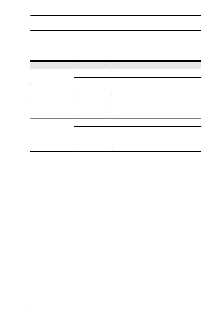
Device Category Device Model Device Name
ATEN Control Box VK1100 ATEN Compact Control Box
VK2100 ATEN Control Box
ATEN Control Pad VK0100 8-Button Control Pad (US, 1 Gang)
VK0200 12-Button Control Pad (EU, 2 Gang)
ATEN Keypad VK108US 8-Button Keypad (US, 1 Gang)
VK112EU 12-Button Keypad (EU, 2 Gang)
ATEN Extension Box VK224 4-Port Serial Expansion
VK236 6-Port IR/Serial Expansion Box
VK248 8-Channel Relay Expansion Box
VK258 8-Channel Digital I/O Expansion Box

ATEN Control System User Manual
xii
Chapter 6, Remote PC Control
Explains how to set up your computer for remote control from a licensed
device and provide a complete description of the supported control actions.
Chapter 7, ATEN Control System App
Provides a complete description of the ATEN mobile app and how to use it to
operate devices connected to the ATEN Control System.
An Appendix
Provides specifications and other technical information regarding the ATEN
Control System.
Conventions
This manual uses the following conventions:
Monospaced Indicates text that you should key in.
[ ] Indicates keys you should press. For example, [Enter] means to
press the Enter key. If keys need to be chorded, they appear
together in the same bracket with a plus sign between them:
[Ctrl+Alt].
1. Numbered lists represent procedures with sequential steps.
♦Bullet lists provide information, but do not involve sequential steps.
→Indicates selecting the option (on a menu or dialog box, for
example), that comes next. For example, Start
→
Run means to
open the Start menu, and then select Run.
Indicates critical information.

ATEN Control System User Manual
xiii
Terminology
Product Information
For information about all ATEN products and how they can help you connect
without limits, visit ATEN on the Web or contact an ATEN Authorized
Reseller. Visit ATEN on the Web for a list of locations and telephone numbers:
Terminology Description
ATEN Controller,
controller
ATEN Controller or controller refers to all models of ATEN Control
Box (VK1100 and VK2100) and ATEN Control Pad (VK0100 and
VK0200).
ATEN Control Box,
Control Box
ATEN Control Box or Control Box refers to all models of ATEN
Control Box, including the VK2100 Control Box and the VK1100
Compact Control Box.
Viewer, Profile A Viewer or Profile is a software control interface users
customize to control and operate devices in their control system.
A Viewer or Profile is configurable using ATEN Configurator and
applied to a supported hardware control device, such as a mobile
device, ATEN Keypad, or ATEN Control Pad to be able to
function.
Project A project is a set of configuration for an ATEN Control System,
including configuration of one or more controllers, managed
devices, and profiles.
International http://www.aten.com
North America http://www.aten-usa.com

ATEN Control System User Manual
xiv
This Page Intentionally Left Blank

1
Chapter 1
Introduction
Overview
The ATEN Control System, incorporating the ATEN Control Box/ATEN
Control Pad (controller), the ATEN Configurator software (VK6000), and the
ATEN Control System App is a standard Ethernet-based management system
that connects all hardware devices in a room or large facility to provide
centralized control of devices directly and effortlessly via a mobile device. The
ATEN controller works as the main controller that provides great connectivity
to all sorts of hardware devices commonly seen in a room. After connecting the
hardware, the ATEN Configurator (VK6000) provides simple setup of the
devices with easy step by step configuration. The ATEN Control System App
then connects you to the controller from any iOS, Android or Windows mobile
device / tablet computer which empowers you with mobility to control all the
hardware devices, in different rooms, whenever and however you like.
ATEN Control Box/Control Pad easily deploys into an existing installation and
integrates seamlessly with ATEN VanCryst pro-AV products and nearly any
other hardware devices found in a room, including AV equipment, lighting,
conference systems, air conditioning, motion sensors, power switches and
many more. The controller serves as the central platform where hardware
devices are connected – to be monitored, managed, and controlled directly via
a tailor-made GUI from any iOS, Android, or Windows mobile device.
The VK6000 Configurator software facilitates quick setup and control of the
devices in a few easy steps via an intuitive GUI. The VK6000 walks you
through configuring the hardware, designing the control interface, and
uploading this configuration to the controller. To provide control of the
connected devices, you can create and customize a Viewer, a control interface
for mobile devices and via the ATEN Control System App from any iOS,
Android or Windows mobile device. Through an Ethernet connection, the
ATEN Control System App enables you to edit and download Viewers from
the controller via a point-n-tap user interface. Each Viewer is a customized
control interface that grants you quick access to target and control hardware

ATEN Control System User Manual
2
devices. Use of any Viewer is protected with password authentication to ensure
secure access.
The ATEN Control System is perfectly applicable in meeting rooms,
conference centers, boardrooms, classrooms or any room that requires central
and mobile control of a variety of hardware devices through a streamlined
management system with optimum efficiency and performance.

Chapter 1. Introduction
3
Benefits
Intelligent Control
The ATEN Control System makes the interactions between your hardware
devices smarter. Pre-programmed actions and triggers can provide a fully
automated series of advanced operations that allow your devices to respond to
each other intelligently, making your whole solution run smarter and smoother.
Optimized Performance
The ATEN Control System has optimized the communication protocols that
not only maintain a near-zero response time but also feature data encryption for
extra protection.
Simplified Setup
No matter how large the room or how complicated the hardware, the ATEN
Control System can be deployed in 3 easy steps: connect the hardware,
configure the system and upload Viewers via a smart mobile app. Through an
intuitive GUI, the process for setting up the controls for every room is simple
and customizable, via straightforward predefined commands and macros, that
do not require you to have complicated programming skills.
Effortless Expandability
With a range of expansion boxes available, the ATEN Control System
installation can grow to accommodate additional Serial, Relay and IR devices.
Furthermore, the ATEN Library has 10,000+ device drivers and grows as you
add new devices to the existing database via the Database Generator, making
it expandable and easily manageable, whatever the size or scope of the
installation.
User Centered Convenience
An advanced, single-software solution creates an intuitive interface for any
mobile device, while specific needs are customizable by selecting from an
extensive library of actions and design elements to customize the control panel.

ATEN Control System User Manual
4
In addition, the ATEN Control System provides various support services that
include driver downloads, database generation and upgrade tools – to help
system integrators build easy-to-control environments effortlessly.
On-the-Go Control
Intuitive system control can start with one room and scale up to multiple rooms
in the same area or across regions. Toggling between Viewers on an iOS,
Android or Windows mobile device facilitates control of different rooms with
simple point-n-tap operations. In addition, multiple mobile devices can be
authorized with access to control the same room or multiple rooms, providing
you with flexible, enhanced mobility, and tight security.

Chapter 1. Introduction
5
Features
ATEN Control Box
Supports various connection interfaces:
DC outputs for power supply connections
VK2100: equipped with 4 DC outputs
VK1100: equipped with 1 DC output
1 x USB port for easy Viewer upload
IR Learning function for adding IR device drivers
Supports native KNX IP for building management systems
Telnet, TCP, UDP, ONVIF, PJLink, HTTP, and HTTPS compliant
Supports project file backup
Supports up to 8 ATEN Keypads
Web GUI for easy system configuration
2 free licenses for mobile control*
Supports SSH communication for data monitoring
Rack-mountable
Note: If you need more than two licenses for mobile control, contact your
local sales representative.
Interface VK2100 Control Box VK1100 Compact Control Box
Serial Port 6 2
IR/Serial Port 4 2
Relay Channel 4 4
I/O Channel 4 -
Ethernet Port 1 1

ATEN Control System User Manual
6
ATEN Control Pad
Supports various connection interfaces:
2 RS-232 serial ports
2 relay channels
1 digital input port
1 Ethernet port
Designed to mount in 2-gang EU type and MK type junction boxes (for
VK0200)
Fully customizable layout
VK0100: 14 layout variations using 4 to 8 buttons
VK0200: 125 layout variations using 6 to 12 buttons
Customizable button text engraving service
System LED indicators for quick connection status check
Dual-color LEDs for clear indication in dark environments
Redundant power supplies (DC power and PoE)
Supports native KNX IP for building management systems
Telnet, TCP, UDP, ONVIF, PJLink, HTTP, and HTTPS compliant
Supports project file backup
Web GUI for easy system configuration
Supports SSH communication for data monitoring
Note: To control your setup using a mobile device, contact your local sales
representative to purchase licenses for mobile control.

Chapter 1. Introduction
7
ATEN Configurator
Simple Viewer setup with easy configuration steps via intuitive GUI
Customizable GUI to be used on mobile devices and PC
Supports ControlAssist that allows PC control (PC shutdown, media files,
PowerPoint files)*
Built-in Database Generator for device driver setup and overall device
management.
Built-in ATEN Library comprising 10,000+ device drivers and complete
ATEN VanCryst product drivers
Event scheduling
Two-way communication enables user-defined event monitoring to
automatically trigger the next actions
Test tool to verify commands in action before uploading the Viewer to the
ATEN controller
Simulator to simulate and review the customized GUI before uploading
Note: For details on the supported PC control actions, see Supported PC
Control Actions, page 215.
ATEN Control System App
Allows administrators central control of multiple rooms via Viewers on a
mobile device or tablet computer
Restrict user access to Viewers via password authentication
Synchronization of system controls amongst multiple mobile devices and
tablet computers
Any iOS, Android, or Windows mobile device can be used to control the
system – no need to purchase costly

ATEN Control System User Manual
8
ATEN Keypads
Fully customizable layout
VK108US: 14 layout variations using 4 to 8 buttons
VK112EU: 125 layout variations using 6 to 12 buttons
System LED indicators for quick connection status check
Dual-color LEDs for clear indication in dark environments
Easy ID pairing with ATEN controller for Ethernet communication
Scalability – an ATEN controller can connect up to 8 Keypads
Versatile modes support flexible behavior settings for each button
Intuitive Web GUI for easy configuration
Redundant power supplies (DC power and PoE)
Button engraving service

Chapter 1. Introduction
9
Requirements
Prepare the following equipment and make sure your equipment meets the
minimum requirements specified below.
Hardware devices to be controlled by your ATEN controller
Bi-directional RS-232/422/485 serial devices
One-way IR or serial transmitter hardware devices (for Control Box
only)
Relay hardware devices
Digital input hardware devices (for VK2100 and Control Pad only)
Digital output hardware devices (for VK2100 only)
Ethernet-controlled PJLink, Telnet, ONVIF, TCP, UDP, HTTP, or
HTTPS devices
KNX IP interfaces for connecting KNX-compliant devices
Cables
One Cat 5e/6 Ethernet cable used to connect the ATEN controller to
the local area network
(Optional) For serial devices with DB9 connectors, use standard
straight-through cables.
A computer for configuring your ATEN Control System
Make sure the computer runs Windows 7, 8, 8.1, 10, or any of the later
versions.
Make sure to install .NET Framework version 4.5 or any of the later
versions to the computer before using the ATEN Database Generator.
(Optional) Up to 10 mobile devices for remote control
Note: A license is required for each mobile device. For detailed
information, see Licenses for Mobile Control, page 59.

ATEN Control System User Manual
10
Accessories
Optionally purchase ATEN accessories to enhance the functionality of your
Control System. For more information, visit the ATEN website. Contact your
ATEN dealer to purchase these accessories.
Model Description
2XRT-0004G Full Range IR Emitter (1.8 m)
2X-031G Single Rack Mount Kit for VK1100
VK108US 8-button Keypad (US, 1 Gang)
VK112EU 12-button Keypad (EU, 2 Gang)
VK224 4-Port Serial Expansion Box
VK236 6-Port IR/Serial Expansion Box
VK248 8-Channel Relay Expansion Box
VK258
8-Channel Digital I/O Expansion Box
SA0141 DB9-F to RJ45-F Adapter
SA0145 RJ45-F to DB9-M Adapter
11
Chapter 2
Hardware Setup
ATEN Control Box
Panel Components
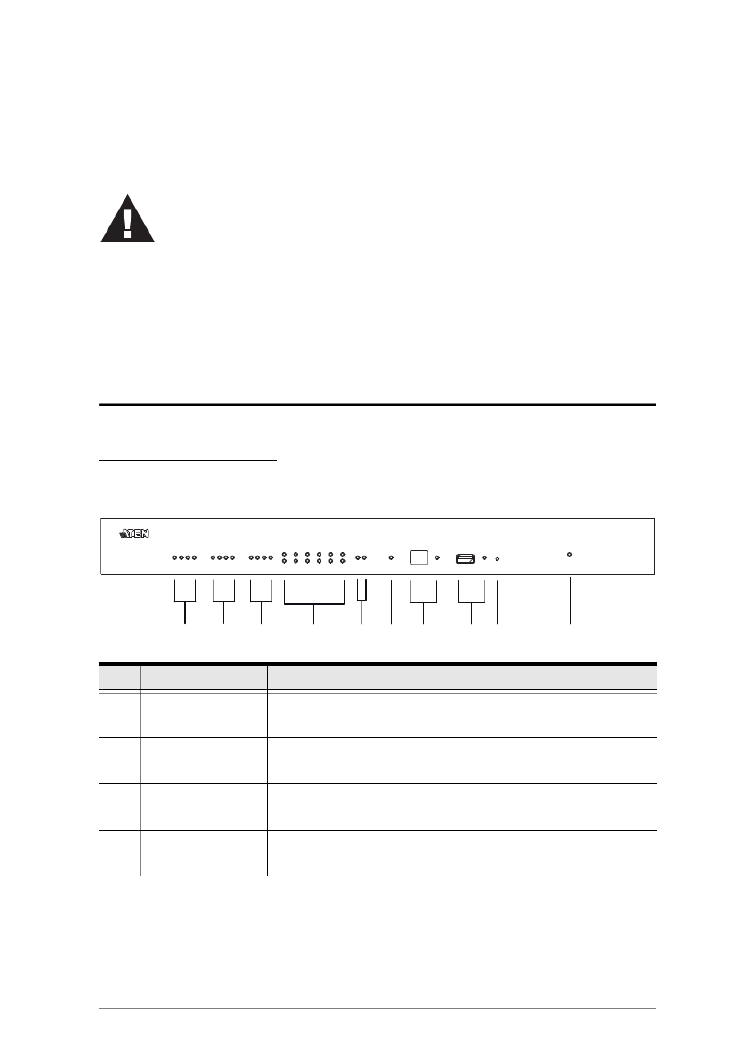
VK2100 Front View
No. Component Description
1 Relay LED The LED lights green to indicate an active device connection
(closed loop).
2 IR/Serial LED The LED lights green to indicate an active device connection
and IR/Serial signals are being transmitted.
3 I/O LED The LED lights green to indicate an active device connection
and I/O signals are being transmitted.
4 Serial LED The LED (1~6) lights green to indicate serial signals are
being transmitted.
1. Important safety information regarding the placement of this
device is provided on Safety Instructions, page 233. Please
review it before proceeding.
2. Make sure that the power to all devices connected to the
installation are turned off. You must unplug the power cords of
any computers that have the Keyboard Power On function.
1
10
5
2 4
3 6 7 8 9

ATEN Control System User Manual
12
5 Ethernet LED The LEDs provide information about the network
connection:
Link: The LED blinks green to indicate Ethernet signals
are being transmitted.
ACT: The LED lights green to indicate 100Mbps transmis-
sions.
6 DC Overload LED The LED lights orange to indicate DC output exceeds
maximum output.
Note: When the LED lights orange, please unplug any of the
connected devices to keep its total output under 24W.
7 IR Receiver / LED This IR receiver passes the functions of a remote control to
the VK2100 in learning mode. The distance between the IR
remote and the receiver window should be kept under 10cm
with a direct line of sight.
The LED blinks green to indicate the unit is ready to
receive signals from an IR remote control.
8 USB Port / LED This is where a USB device plugs in to upload Viewers to
the VK2100.
The LED blinks green to indicate that Viewers are being
uploaded, and lights green to indicate that the upload was
successful.
The LED lights orange to indicate Viewers were not
successfully uploaded.
9 Reset Switch
To clear all the configurations except the network
settings, press and hold the Reset Switch for 8 seconds.
To reset the network settings, press the Reset Switch
once.
10 Power LED Lights green when the unit is turned on.
No. Component Description
Chapter 2. Hardware Setup
13
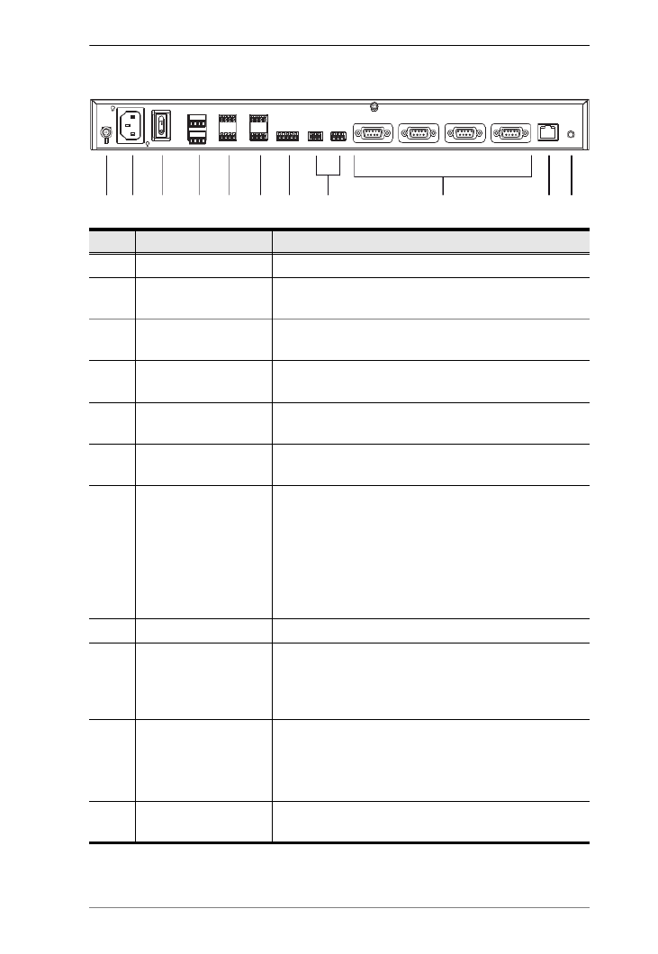
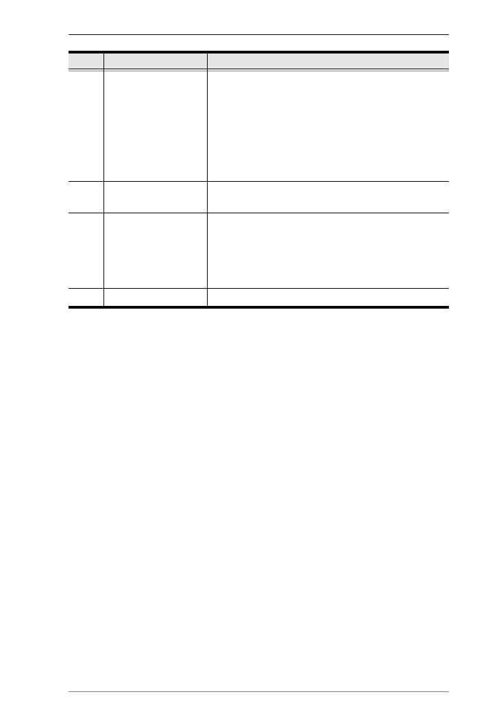
VK2100 Rear View
No. Component Description
1 Grounding Terminal The grounding wire attaches here.
2 Power Socket This is a standard 3-pin AC power socket. The power
cord from an AC source plugs in here.
3 Power Switch This is a standard rocker switch that powers the unit
on and off.
4 DC Output Ports Four outputs provide a total power output of 24W /2A
max.
5 Relay Channels Four channels; normally open, isolated relays with a
contact rating of 24VDC, 2A max.
6 IR / Serial Ports Four IR ports that can also be configured as RS-232
TX ports. pin1: Signal / pin2: Ground.
7 I/O Channels Four channels that can be configured as digital input
or digital output ports.
Digital Input: 0-24VDC programmable input range or
contact closure with +12VDC pull-up
Digital Output: 250mA sink from 12VDC
Pin1~4: Signal / Pin5: Ground
8 RS-232 Serial Ports Two RS-232 ports with TX/RX functions supported.
9 RS-232/422/485
Serial Ports
Four ports with supported RS-232/422/485 conversion
by pin assignment and RTS/CTS flow control. The
RS232, RS422, or RS485 connection is defined by
pin. For pin assignments, see page 33.
10 Ethernet Port This RJ-45 port is used for the network connection. If
no IP address is assigned within 30 seconds, the
default IP settings will be used:
IP: 192.168.0.60 / mask: 255.255.255.0
11 Controller ID Switch This 16-segment switch is used to set an ID for the
controller.
1 2 3 4 5 6 8
7 11
910

ATEN Control System User Manual
14
VK1100 Front View
No. Component Description
1 Relay LED The LED lights green to indicate an active device
connection (closed loop).
2 IR/Serial LED The LED lights green to indicate an active device
connection and IR/Serial signals are being transmitted.
3 Serial LED The LED (1~2) lights green to indicate serial signals
are being transmitted.
4 Ethernet Link / ACT
LED
The LEDs provide information about the network
connection:
Link: The LED blinks green to indicate Ethernet sig-
nals are being transmitted.
ACT: The LED lights green to indicate 100Mbps
transmissions.
5 DC Output Overload
LED
The LED lights orange to indicate DC output exceeds
maximum output.
Note: When the LED lights orange, please unplug any
of the connected devices to keep its total output under
12W.
6 IR Receiver / LED This IR receiver passes the functions of a remote
control to the VK1100 in learning mode. The distance
between the IR remote and the receiver window
should be kept under 10cm with a direct line of sight.
The LED blinks green to indicate the unit is ready to
receive signals from an IR remote control.
1
2
3 5 6 7 8
4
9 10
Chapter 2. Hardware Setup
15
7 USB Port / LED This is where a USB device plugs in to upload Viewers
to the VK1100.
The LED blinks green to indicate that Viewers are
being uploaded, and lights green to indicate a
successful upload of Viewers.
The LED lights orange to indicate that Viewers were
not successfully uploaded.
8 Controller ID Switch This 16-segment switch is used to set an ID for the
controller.
9 Reset Switch
To clear all the configurations except the network
settings, press and hold the Reset Switch for 8
seconds.
To reset the network settings, press the Reset
Switch once.
10 Power LED Lights green when the unit is turned on.
No. Component Description
ATEN Control System User Manual
16
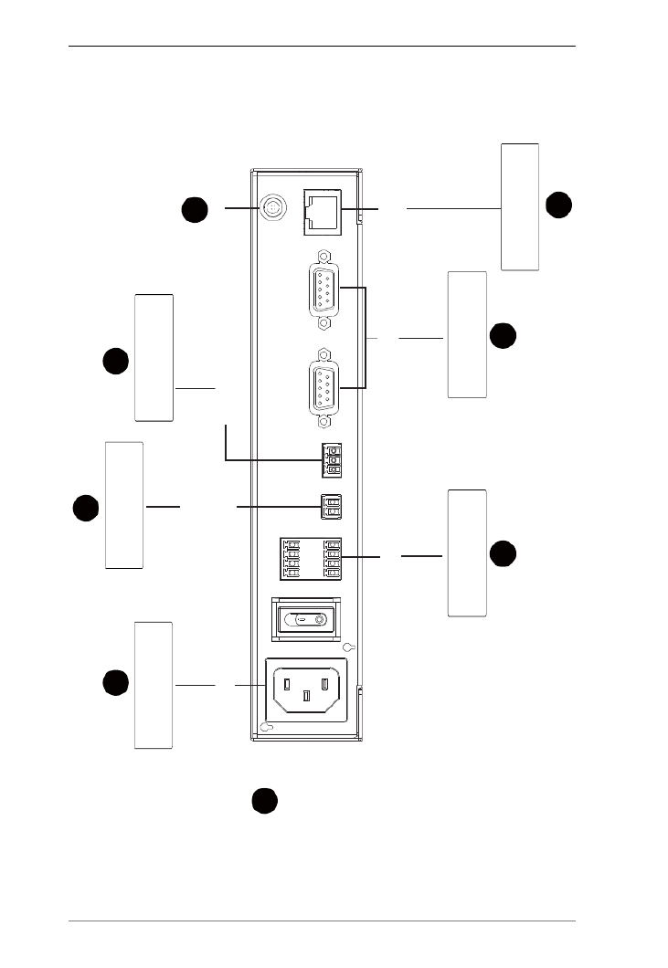
VK1100 Rear View
No. Component Description
1 Power Socket This is a standard 3-pin AC power socket. The power
cord from an AC source plugs in here.
2 Power Switch This is a standard rocker switch that powers the unit
on and off.
3 Relay Channels Four channels; normally open, isolated relays with a
contact rating of 24VDC, 2A max.
4 DC Output Ports One output provides a total power output of 12W max.
5 IR / Serial Ports Two IR ports that can also be configured as RS-232
TX ports. pin1: Signal / pin2: Ground.
6 RS-232/422/485
Serial Ports
Two ports with supported RS-232/422/485 conversion
by pin assignment and RTS/CTS flow control. The
RS232, RS422, or RS485 connection is defined by
pin. For pin assignments, see page 33.
7 Ethernet Port This RJ-45 port is used for the network connection. If
no IP address is assigned within 30 seconds, the
default IP settings will be used:
IP: 192.168.0.60 / mask: 255.255.255.0
8 Grounding Terminal The grounding wire attaches here.
1 2 3 4 5 76
8

Chapter 2. Hardware Setup
17
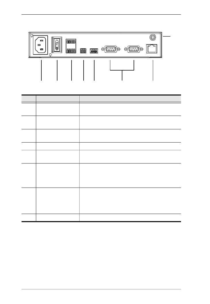
Rack Mounting the ATEN Control Box
VK2100
The VK2100 can be mounted in a 19” (1U) system rack. To install the device
in a rack, do the following:
1. Use the M3 x 8 Phillips head hex screws supplied with the Rack Mount
Kit to screw the rack mounting brackets onto the front of the unit.
2. Position the unit in the front of the rack and align the holes in the mounting
brackets with the holes in the rack.
3. Screw the mounting brackets to the rack.
ATEN Control System User Manual
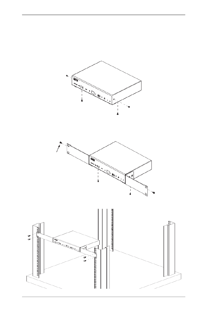
18
VK1100
Optionally purchase an ATEN Rack Mount Kit to install VK1100 in a 19” (1U)
system rack. To install the device in a rack, do the following:
1. Remove the side and bottom screws from the front of the VK1000.
2. Use the two bottom screws removed in step 1 to secure the bottom of the
brackets, and two M3X6 hexagon screws (from the rack mount kit) to
secure the side of the bracket to the VK1100.
3. Screw the mounting brackets to the rack.
M3X6
Hexagon
Screw

Chapter 2. Hardware Setup
19
Control Box Connections
Installation of the Control Box is a matter of connecting the appropriate wires.
Refer to the installation diagrams on the pages that follow to setup each device
and use the instructions below as a guide (each step provides a corresponding
page with diagram for the VK2100 and VK1100), and do the following:
Connect the hardware devices to the Control Box using these instructions:
1. Use a grounding wire to ground the unit by connecting one end of the wire
to the grounding terminal, and the other end of the wire to a suitable
grounded object.
Note: Do not omit this step. Proper grounding helps prevent damage to the
unit from surges or static electricity.
2. Use a Cat 5e/6 cable to connect the Control Box’s Ethernet port to the
network.
3. Use the Controller ID Switch to assign an ID to this unit.
Note: It is possible to install more than 16 controllers under the same
subnet. In which case, the 17th controller and the ones added after
that will each be sharing its ID with another controller. If you have
any ATEN Expansion Box and/or Keypad connected to controllers
using shared IDs, reconfigure the connection mode. For details, see
Controller Properties, page 89.
4. Use the DC Output terminals to wire 12VDC power connections using the
instructions on page 25.
5. Use the Relay terminals to wire relay device connections using the
instructions on page 27.
6. Use the IR/Serial (TX) terminals to wire IR or serial device connections
using the instructions on page 28.
7. Use the Digital I/O terminals to wire digital Input/Output device
connections using the instructions on page 30.
8. Use the RS-232 terminals to wire RS-232 serial device connections using
the instructions on page 32.
9. Use the DB-9 ports to wire RS-232/422/485 serial device connections
using the instructions on page 33.

ATEN Control System User Manual
20
10. Connect IP-based devices to the same network as the Control Box. Refer
to Ethernet, page 34 for details.
Note:
For KNX-compliant devices, connect the devices to a KNX IP
interface, and then connect the KNX IP interface to the network where
the Control Box is installed.
To check if the KNX functions are supported by the Control Box, see
Specifications, page 236.
11. Plug the power cord supplied with the package into the Control Box’s 3-
prong AC socket and then into an AC power source.

Chapter 2. Hardware Setup
21
VK2100 Installation Diagram
Ethernet
Connect to
RS232/422/485 devices
12VDC
Power
Output
IR / Serial
Relay Digital I/O
Controller ID
Switch
Ground
Power Input
RS-232 RS-232 / 422 / 485
Connect to network via
Cat 5e cable
Connect to RS-232
serial devices
Connect to provide
12VDC power supply
Connect to IR or
RS-232 devices
Conect to digital input or
digital output devices
Connect to switch or
motor devices
Power
Outlet
6
7
3
4 298
511
1
ATEN Control System User Manual
22
VK1100 Installation Diagram
Ethernet
Ground
Connect to network via
Cat 5e cable
Power Input
Power
Outlet
Relay
Connect to switch or
motor devices
12VDC
Power
Output
Connect to provide
12VDC power supply
IR / Serial
Connect to IR or
RS-232 devices
Connect to
RS232/422/485 devices
RS-232 / 422 / 485
Controller ID
Switch is on
the VK1100’s
front panel.
6
3
4
2
95
11
1
Chapter 2. Hardware Setup
23
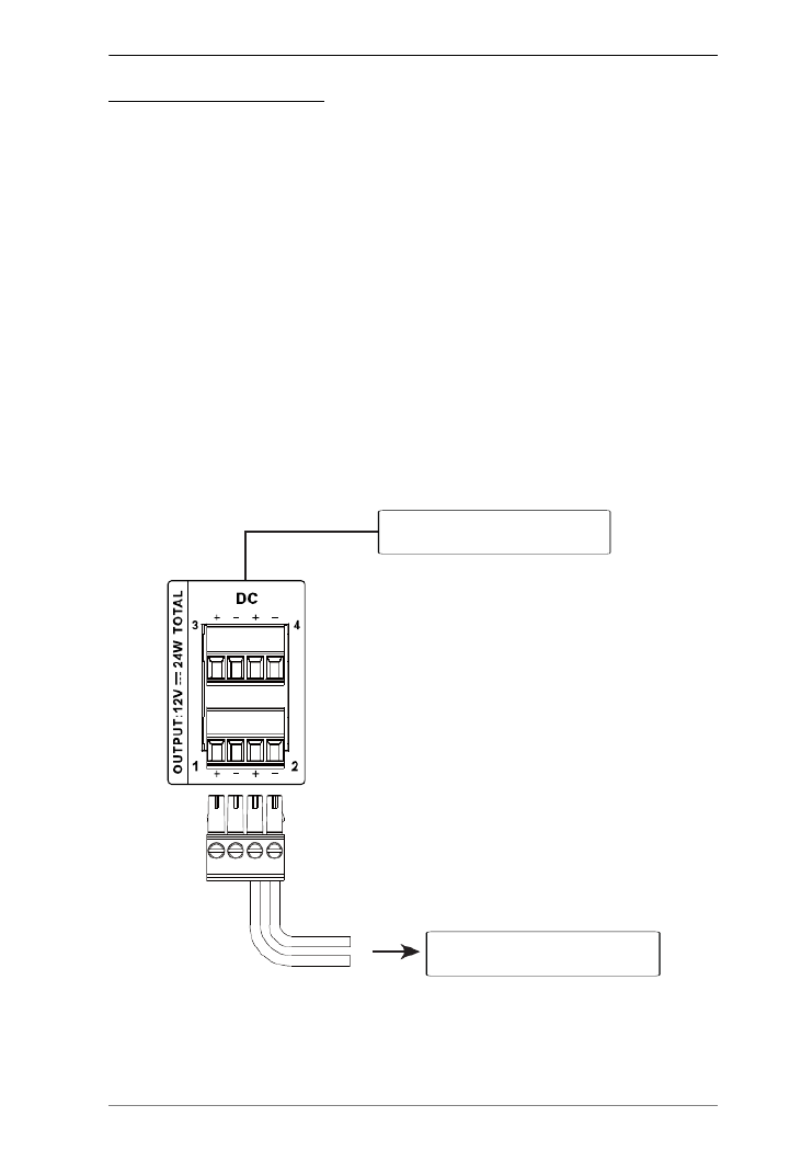
12VDC Power Output
One or four (VK1100 / VK2100) ports provide 12VDC of power with a total
of 12 or 24 watts. The output can power one or four (VK1100 / VK2100)
independent hardware devices, one or four (VK1100 / VK2100) loops for
connected relay devices, or one or four (VK1100 / VK2100) digital output
devices. If the combined current of the ports exceeds 1A (VK1100) or 2A
(VK2100), the DC Power Overload LED lights orange, an alarm beeps three
times and the ports are turned off. To return power to the ports, power off the
Control Box, unplug all hardware connected to the 12VDC Power Output
ports, power on the Control Box, and then plug in the hardware devices, one at
a time, ensuring the current does not exceed 1A or 2A.
The diagrams on the next three pages show ports on the VK2100. The VK1100
is the same except that it has fewer 12VDC terminal blocks and no I/O ports.
Independent Power Supply
Power Supply: 12VDC, 2A Max
(24W shared by 4 ports)
Provides 12VDC power to
independent hardware devices.
Connects to
4 x 12VDC Output Ports
ATEN Control System User Manual
24
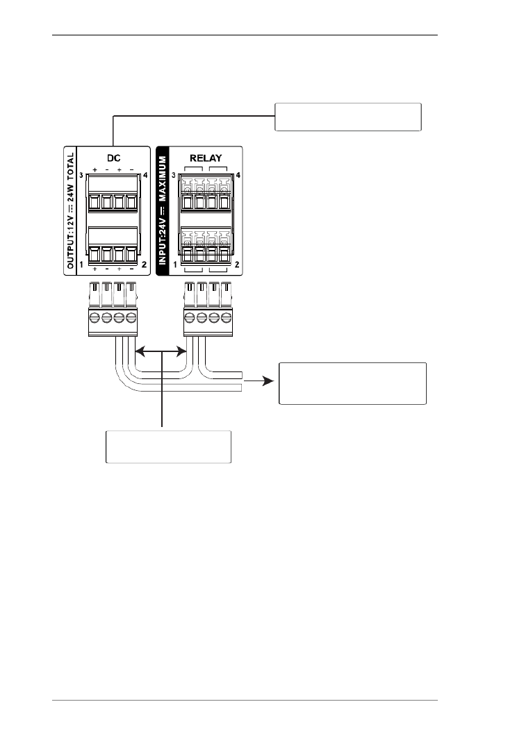
Relay Power Supply
Connects to
Provides 12VDC power
for the relay loop.
Power Supply: 12VDC, 2A Max
(24W shared by 4 ports)
4 x 12VDC Output Ports
Switch, Screen, Projector Lift,
Lighting, Motorized Equipment,
Motion Device, etc.
Chapter 2. Hardware Setup
25
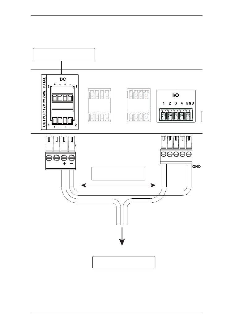
Digital Output Power Supply (VK2100 only)
Power Supply: 12VDC, 2A Max
(24W shared by 4 ports)
Connects to
Switch, Screen, Projector Lift,
Lighting and Equipment Control.
4 x 12VDC Output Ports
Provides 12VDC power
for the digital output loop.

ATEN Control System User Manual
26
Digital Output Dual Power Supply (VK2100 only)
Power Supply: 12VDC, 2A Max
(24W shared by 4 ports)
4 x 12VDC Output Ports
Provides 12VDC power
for the digital output loop.
Provides connection to
digital output #2.
Provides connection to
digital output #1.

Chapter 2. Hardware Setup
27
Relay
These four Relay channels provide connections to control hardware devices
such as electric screens, projector lifts and other motorized equipment. Each
relay is normally open by default.
Normally
Open Closed
Normally Open, Isolated Relays
Contact Rating: 24VDC 2A Max
Switch, Screen, Projector Lift,
Lighting, Motorized Equipment,
Motion Device, etc.
Connects to
4 x Relay Channels

ATEN Control System User Manual
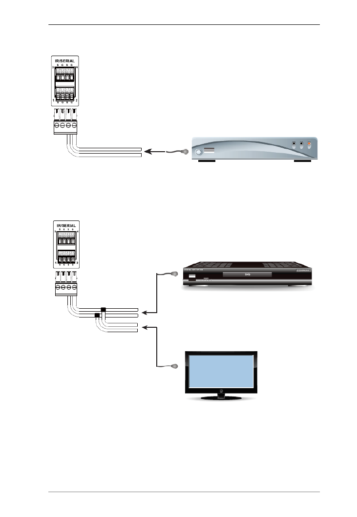
28
IR / Serial
These two or four (VK1100 / VK2100) ports can be configured to connect IR
and RS-232 devices. By default the ports are set to transmit IR signals. Use the
ATEN Configurator software to configure the ports for RS-232 signals. The
diagram below shows ports on the VK2100. The VK1100 is the same except
that it has fewer terminals blocks and the Uni-directional setting is (0 to 5 V).
IR Connection: Connect a transmitter cable to the IR and Ground ports on the
Control Box and install the IR transmitter on or near the device's IR receiving
port, as shown on page 29.
Serial Connection: Connect the device's receiver (RX) and ground ports to the
Serial (TX) and Ground ports on the Control Box. Next configure the same
serial port setting on the Control Box and serial device so that they can
communicate.
Uni-directional (+ -5 V)
Baud Rate: 300 to 115200
(default: 9600)
Data Bit: 8 (default) or 7
Stop Bit: 1 (default) or 2
Parity: None (default), Even or
Odd
IR: Blu-ray / DVD Player, TV,
Audio Receiver, Projector, etc.
RS-232: Camera, Projector,
Switch, Audio Mixer, Multimedia
Device, etc.
Connects to
4 x RS-232 Ports
TTL Level (0 to 5 V)
Carrier Frequency:
10kHz~455kHz
4 x IR Ports
or
VK2100
Chapter 2. Hardware Setup
29
One IR Transmitter
Two IR Transmitters
IR Receiver
Unidirectional IR
2 x IR Transmitters
IR Receiver
ATEN Control System User Manual
30
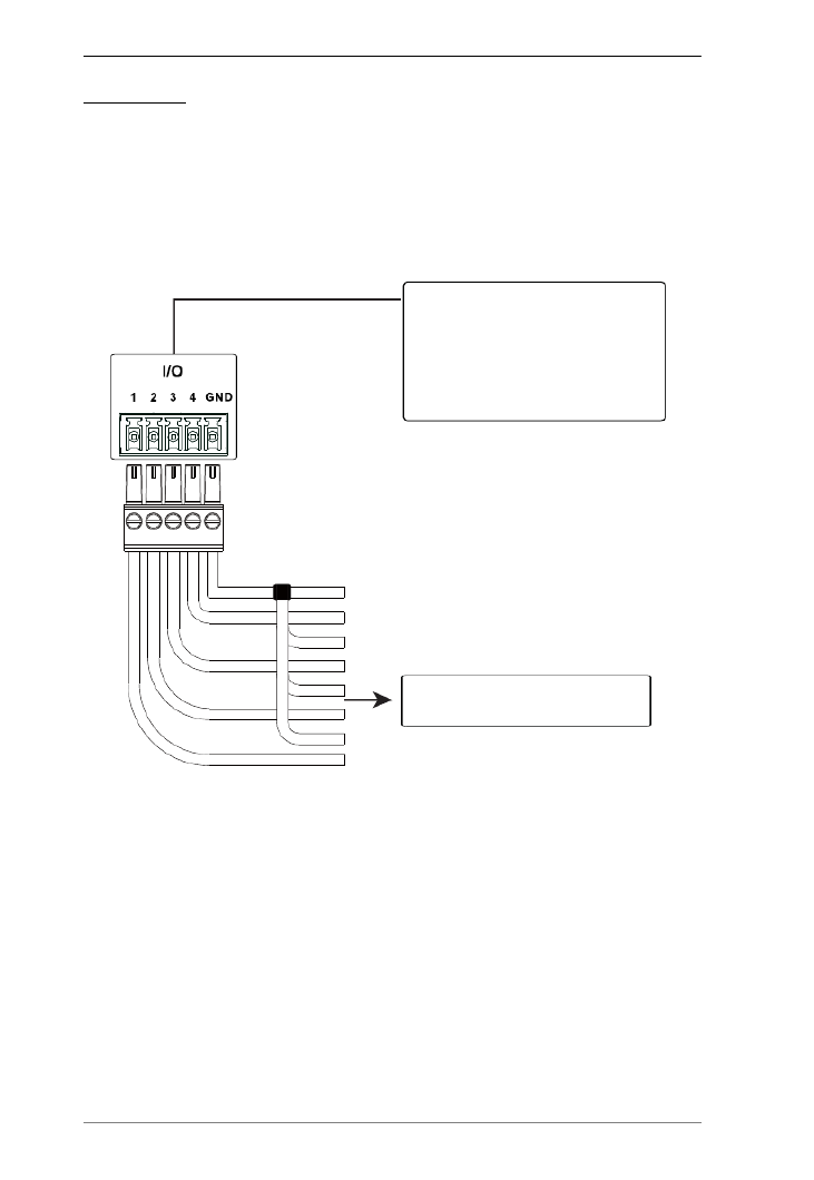
Digital I/O
The four channels on the VK2100 can be used to connect Digital Input or
Digital Output hardware devices such as switches, sensors, LEDs and relays.
Each channel can be configured as either an Input (VDC), Input (Dry Contact)
or Output channel.
Digital Input (Dry Contact):
Digital inputs are hardware devices (switches, sensors, monitors) with two
circuit signals – open and closed. These two signals provide indicators from
sensors or switches of an event. An event can be the on/off power, dry contact,
sensor or switch status from a device. This information is used to trigger events
and functions through the VK2100.
Digital Input (VDC):
Digital input 12VDC hardware devices (temperature, current and monitor
sensors) provide voltage signals between 1 and 24. A digital input port detects
if a voltage is above/below a specific threshold (1 to 24). If the voltage
coming from a hardware device is higher than the set value, the VK2100 will
detect the digital input as high. If the voltage coming from a hardware device
Connects to
4 x Programmable Digital
Input Channels
Digital Input
VDC Mode:
-Input Voltage Range: 0 to 24 VDC
-Programmable Range: 1 to 24 VDC
Dry Contact Mode:
-Pull-up 2k ohms to + 12 VDC
Digital Input: Switches, Sensors
Monitors and Button Triggers.

Chapter 2. Hardware Setup
31
is lower than the set value, the VK2100 will detect the digital input as low.
This information is used to trigger events and functions through the VK2100.
Digital Output:
Digital output channels provide non-powered dry contact (open and closed)
circuit control of hardware devices such as electric screens, projector lifts and
other motorized equipment. Devices connected to the Digital Output port must
be connected through a Relay Module, as shown below.
Digital Output: Switch, Screen,
Projector Lift, Lighting and
Equipment Control.
Connects to
4 x Programmable Digital
Output Channels
Digital Output:
250 mA sink from 12 VDC
Relay
Module
ATEN Control System User Manual
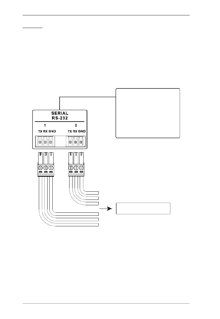
32
RS-232
The two bi-directional RS-232 ports on the VK2100 provide serial control of
hardware devices (projectors, matrix switches, etc.) and receive status
messages from the connected devices. For bi-directional RS-232 control, the
transmit, receive and ground pins must be wired on both the VK2100 and
hardware device. Each hardware device requires different wiring. Please
consult each hardware device's manual for details.
Projector, Matrix Switch,
Camera, etc.
Baud Rate: 300 to 115200
(default: 9600)
Data Bit: 8 (default) or 7
Stop Bit: 1 (default) or 2
Parity: None (default), even or
odd
Connects to
2 x Bi-directional RS-232 Ports

Chapter 2. Hardware Setup
33
RS-232 / 422 / 485
These two or four (VK1100 / VK2100) bi-directional ports provide serial
control of hardware devices (projectors, switches, etc.) with programmable pin
assignments and receive status messages from the connected devices. The
diagram below shows ports on the VK2100. The VK1100 is the same except
that it has fewer ports.
Pin Assignments
RS-232 RS-422 RS-485
Pin2: RX Pin1: RX- Pin3: D+
Pin3: TX Pin2: RX+ Pin4: D-
Pin5: GND Pin3: TX+
Pin7: RTS Pin4: TX-
Pin8: CTS Pin5: GND
Projector, Matrix Switch,
Camera, etc.
Connects to
Configurable by pin assignment
Baud Rate: 300 to 115200
(default: 9600)
Data Bit: 8 (default) or 7
Stop Bit: 1 (default) or 2
Parity: None (default), Even or
Odd
Flow Control: None (default) or
RTS/CTS
4 x Programmable
Bi-directional RS-232/422/485
ATEN Control System User Manual
34
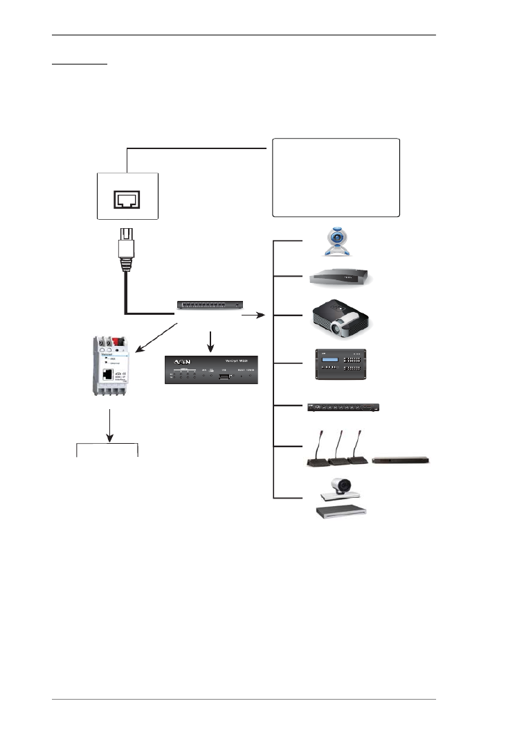
Ethernet
The RJ-45 port provides an Ethernet connection for GUI access (page 55) and
the ability to add up to 25 LAN devices per Control Box or up to 8 LAN devices
per Control Pad, as shown below.
Ethernet
VK224
VK236
VK248
VK258
Expansion Box
SELECT
PDUCURRE N TOUTLET CURRENT IPADDRESSSEN S OR1 SEN SOR2
OUTLET STATUS
ONVIF
TCP
PJLink
Telnet
Telnet
1 x Ethernet Port
The RJ-45 port is used to connect
the Control Box to the network and
access TCP, UDP, PJLink, ONVIF,
HTTP, HTTPS, and Telnet devices.
If the network switch does not
support DHCP, the installed device
will adopt the default IP
address,192.168.0.60
eco PDU
Modular Matrix Switch
Ethernet Switch
UDP
Lighting HVAC Systems
KNX IP Interface
HTTP
HTTPS
Video Conferencing System
Chapter 2. Hardware Setup
35
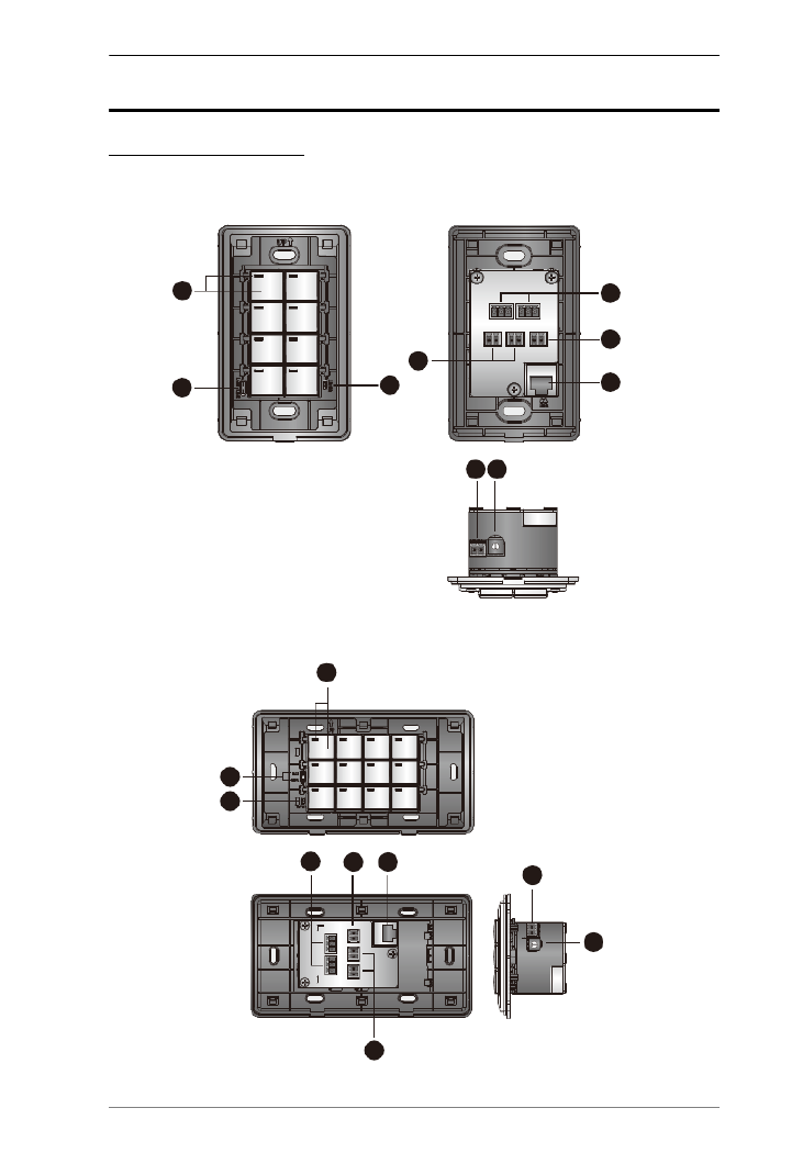
ATEN Control Pad
Panel Components
VK0100
VK0200
23
4
9 8
7
5
1
6
Front View Rear View
Side View
9
8
1
2
3
5
46 7
Front View
Rear View
Side View

ATEN Control System User Manual
36
No. Component Description
1 Buttons and Button
LEDs
Indicate the status of the Control Pad and the
assigned function, e.g. lighting or projector.
When a button LED:
lights orange, the Control Pad is powered on
and the button is off.
lights white, the Control Pad is powered on and
the button is on.
When all button LEDs:
blink orange and white once, the Control Pad is
restoring its default settings.
blink orange and white repeatedly, the Control
Pad is being upgraded for its firmware.
2 System LEDs Contains a LAN and a Link LED to indicate network
connection and data transmission status:
LAN LED lights green to indicate that the Control
Pad is connected to network.
Link LED lights green to indicate that the Control
Pad is actively transmitting and receiving data.
3 Reset Switch
To clear all the configurations except the network
settings, press and hold the Reset Switch for 8
seconds.
To reset the network settings, press the Reset
Switch once.
4 RS-232 Serial Ports Connect up to two RS-232 serial devices.
5 Relay Channels Connect up to two relay devices. Relay contacts are
normally open, isolated with a contact rating of 24 VDC,
1A max.
6 Digital Input Port Connect to one digital input device that supports
programmable input (1 to 5 VDC) or dry contact (pull-up
2k ohms to 5VDC).
7 Ethernet Port Connects to an Ethernet cable to provide power and
access to the network.
8 Control Pad ID Switch Sets an ID for the Control Pad.
9 DC Power Port Connects to a 5V DC power adapter.
Chapter 2. Hardware Setup
37
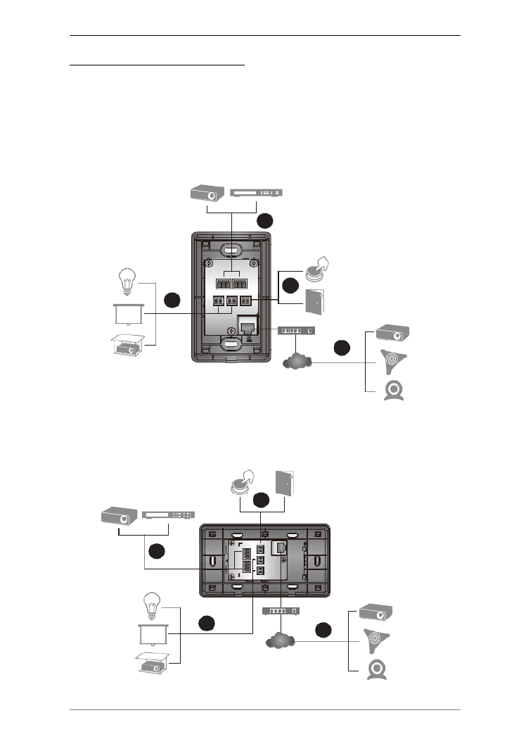
Installing the Control Pads
Installation Steps
Follow the steps below to safely install the Control Pad.
VK0100
VK0200
Screen
Projector Video Switch
Projector
Projector
Lift
Ethernet
Cable
Camera
Network
Lighting
Control
Conference
System
Door
Sensor
Dry Contact
Device
PoE Switch
Relay
RS-232
DI
2
2
2
3
Relay
DI
Screen
Projector
Lift
Lighting
Control
Door
Sensor
Dry Contact
Device
2
Projector
Ethernet
Cable
Camera
Network
Conference
System
PoE Switch
RS-232
Projector Video Switch
2
2
23

ATEN Control System User Manual
38
1. Prepare the installation site.
a) Choose a location where cables are free of interference.
b) Prepare a recession in the wall to accommodate the Control Pad.
Download a CAD diagram from the product web page.
2. Connect the Control Pad to serial, relay, and/or digital input devices using
the supplied terminal blocks.
For details, see RS-232 Serial Connection, page 42, Relay Connections,
page 43, Digital Input Device, page 44 respectively.
Note: To expand connection ports on the Control Pad, install ATEN
Expansion Boxes.
3. To use PoE, connect the Control Pad to a PoE switch via an Ethernet cable.
For details, see Ethernet, page 45.
4. If you do not have power sourcing equipment for PoE, contact your local
sales representative to purchase a power adapter and then follow the steps
below to prepare the power cord.
a) Cut the connector end of the power adapter.
b) Strip 5 mm (0.5 cm) off the insulation cover of the power adapter cable
to expose the +5V wire and the grounding wire.
c) Insert the expose +5V wire and the grounding wire tightly into the
provided 2-pin terminal block connector.
Note: Use a voltmeter to determine the polarity of an exposed wire.
d) Plug the power terminal block to the DC power port on the Control Pad.
+5V
+5V
GND
GND
5mm (+)
(-)
4a
4b
4c

Chapter 2. Hardware Setup
39
5. Use the ID Switch to assign an ID to the Control Pad.
Note: It is possible to install more than 16 controllers under the same
subnet. In which case, the 17th controller and the ones added after
that will each be sharing its ID with another controller. If you have
any ATEN Expansion Box and/or Keypad connected to controllers
using shared IDs, reconfigure the connection mode. For details, see
Controller Properties, page 89.
6. Power on all the devices. The button LEDs light orange.
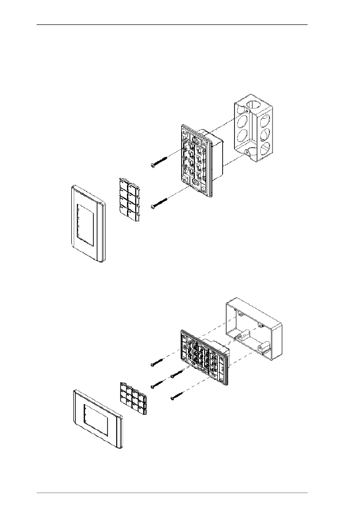
7. Assemble the button caps onto the Control Pad.
a) Assemble button caps of the same row with each other.
b) From the top row, attach each row of button caps to the Control Pad by
pressing on the hinges.
Caution: When removing button caps, place your fingers on the top of
button caps and then press downwards, as illustrated below. Pressing
upwards from the bottom may cause damages to the button caps.
ATEN Control System User Manual
40
8. Mount the Control Pad to the wall.
a) Secure the Control Pad to the wall with self-prepared screws.
b) Install the supplied faceplate to the Control Pad.
VK0100
VK0200 (EU)
ATEN Control System User Manual
42
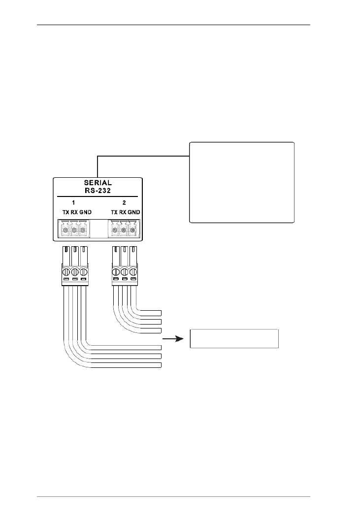
RS-232 Serial Connection
The two bi-directional RS-232 ports on the Control Pad provide serial control
of hardware devices (projectors, matrix switches, etc.) and receive status
messages from the connected devices. For bi-directional RS-232 control, the
transmit, receive, and ground pins must be wired on both the Control Pad and
hardware device. Each hardware device requires different wiring. Please
consult each hardware device's manual for details.
Projector, Matrix Switch,
Camera, etc.
Baud Rate: 300 to 115200
(default: 9600)
Data Bit: 8 (default) or 7
Stop Bit: 1 (default) or 2
Parity: None (default), even or
odd
Connects to
2 x Bi-directional RS-232 Ports

Chapter 2. Hardware Setup
43
Relay Connections
These four Relay channels provide connections to control hardware devices
such as electric screens, projector lifts and other motorized equipment. Each
relay is normally open by default.
Normally
Open Closed
Normally Open, Isolated Relays
Contact Rating: 24VDC 1A Max
Switch, Screen, Projector Lift,
Lighting, Motorized Equipment,
Motion Device, etc.
Connects to
2 x Relay Channels
ATEN Control System User Manual
44
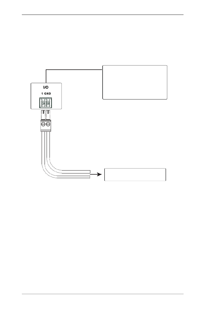
Digital Input Device
The digital input port on the Control Pad can be used to install a digital input
device such as a switch or a sensor. The digital input channel can be configured
to the VDC mode or the Dry Contact mode.
Digital Input (Dry Contact):
Digital inputs are hardware devices (switches, sensors, monitors) with two
circuit signals – open and closed. These two signals provide indicators from
sensors or switches of an event. An event can be the on/off power, dry contact,
sensor or switch status from a device. This information is used to trigger events
and functions through the Control Pad.
Digital Input (VDC):
Digital input 5VDC hardware devices (temperature, current and monitor
sensors) provide voltage signals between 1 and 5. A digital input port detects
if a voltage is above/below a specific threshold (1 to 5). If the voltage coming
from a hardware device is higher than the set value, the Control Pad will
detect the digital input as high. If the voltage coming from a hardware device
is lower than the set value, the Control Pad will detect the digital input as low.
This information is used to trigger events and functions through the Control
Pad.
Connects to
1 x Programmable Digital
Input Channel
Digital Input
VDC Mode:
-Input Voltage Range: 0 to 5 VDC
-Programmable Range: 1 to 5 VDC
Dry Contact Mode:
-Pull-up 2k ohms to + 5 VDC
Digital Input: Switches,
Sensors, Monitors, or Button

Chapter 2. Hardware Setup
45
Ethernet
The RJ-45 port provides an Ethernet connection for GUI access (page 55) and
the ability to add up to 8 LAN devices per Control Pad, as shown below.
Ethernet
VK224
VK236
VK248
VK258
Expansion Box
SELECT
PDUCURRE N TOUTLET CURRENT IPADDRESSSEN S OR1 SEN SOR2
OUTLET STATUS
ONVIF
TCP
PJLink
Telnet
Telnet
1 x Ethernet Port
The RJ-45 port is used to connect
the Control Box to the network and
access TCP, UDP, PJLink, ONVIF,
HTTP, HTTPS, and Telnet devices.
If the network switch does not
support DHCP, the installed device
will adopt the default IP
address,192.168.0.60
eco PDU
Modular Matrix Switch
Ethernet Switch
UDP
Lighting HVAC Systems
KNX IP Interface
HTTP
HTTPS
Video Conferencing System

ATEN Control System User Manual
46
Accessories
ATEN Expansion Box
ATEN Expansion Boxes (sold separately) provide additional ports for a
flexible expansion of the ATEN Control System. This allows you to add and
control additional devices in an environment where more devices are required.
With the advantage of an Ethernet-based connection, the expansion boxes are
easily connected to the ATEN controller via a LAN connection from a variety
of locations across a network. The diagram below provides an example of the
VK224 4-Port Serial Expansion Box setup.
Note:
To add and configure ATEN Expansion Boxes, see Device Configuration
List, page 85 and Expansion Box, page 88.
The available Expansion Box models include:
Model Description
VK224 4-Port Serial Expansion
VK236 6-Port IR/Serial Expansion Box
VK248 8-Channel Relay Expansion Box
VK258 8-Channel Digital I/O Expansion Box
Control Box
Serial Devices
Network
SELECT
PDUCURREN TOUTLET CURRENTIPADDRESSSENSOR 1SENSOR2
OUTLET STATUS
Ethernet
Serial
VK224 (Rear)
Power Distribution
Unit
Video Matrix Projector Camera
Chapter 2. Hardware Setup
47
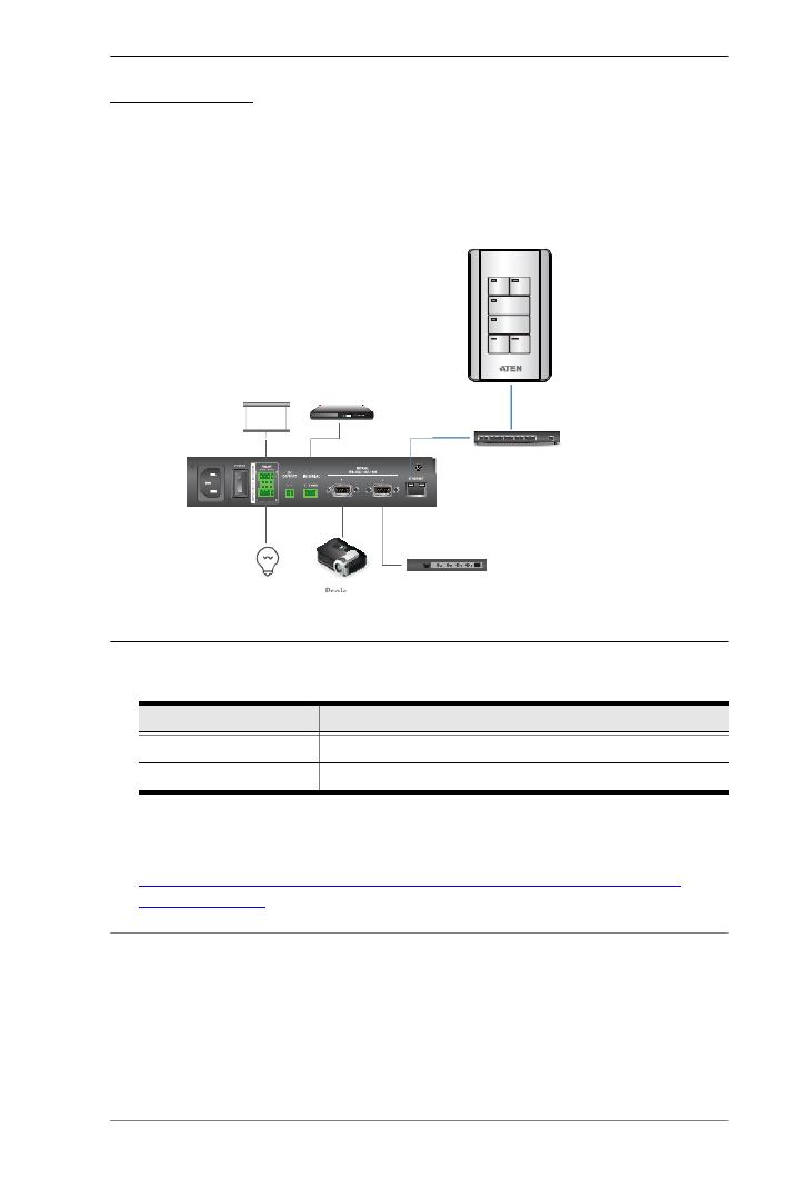
ATEN Keypad
Overview
The ATEN Keypad mounts to a wall to provide control of hardware through a
Control Box. The setup of the Keypad to the Control System can be illustrated
as follows:
Note:
The following Keypad models are available:
You can have your Keypad buttons customized with text engraving. To
make the order, go the this link:
https://www.aten.com/ext_data/global_en/VK_Keypad_Engraving_Service/
aten_keypad.html
Model Description
VK108US 8-Button Keypad (US, 1 Gang)
VK112EU 12-Button Keypad (EU, 2 Gang)
Screen BD-Player
ProjectorLight Video Switch
Ethernet Switch
Powered by PoE
or DC 5V
VK1100
(Rear)
ATEN Keypad

ATEN Control System User Manual
48
Component
The VK108US and VK112EU Keypads share the same hardware layout. For
demonstration purpose, VK112EU is used as an example below.
No. Component Description
1 Buttons VK108US
The Keypad can be customized up to 14 different layouts
using 4 to 8 buttons.
VK112EU
The Keypad can be customized up to 125 different layouts
using 6 to 12 buttons.
2 Button LEDs A button LED:
Lights orange to indicate the power is on.
Lights white to indicate the Keypad is in operation.
Blinks orange and white to indicate that firmware upgrade
is in progress.
3 System LED
Indicators
LAN: lights green to indicate that the Keypad is connected
to LAN.
Link: lights green to indicate that the Keypad is connected
to the assigned Control Box.
4 Reset Pushbutton Press to reset the Keypad to its default network settings.
5 DC Power Plug a power adapter into this DC power input.
6 Keypad ID Switch
(blue)
Sets an ID to the Keypad (1~8).
7 Control Box ID
Switch (black)
Sets the ID of the Control Box (1 ~ 16) to which the Keypad
connects.
2
3
7
5
6
4
1 8
68.51 mm
49.5 mm
28 mm

Chapter 2. Hardware Setup
49
Layout Examples
VK108US
VK112EU
8 LAN Port
Connects the Keypad to LAN
Supplies power (PoE) if a power sourcing equipment is
installed.
No. Component Description
ATEN Control System User Manual
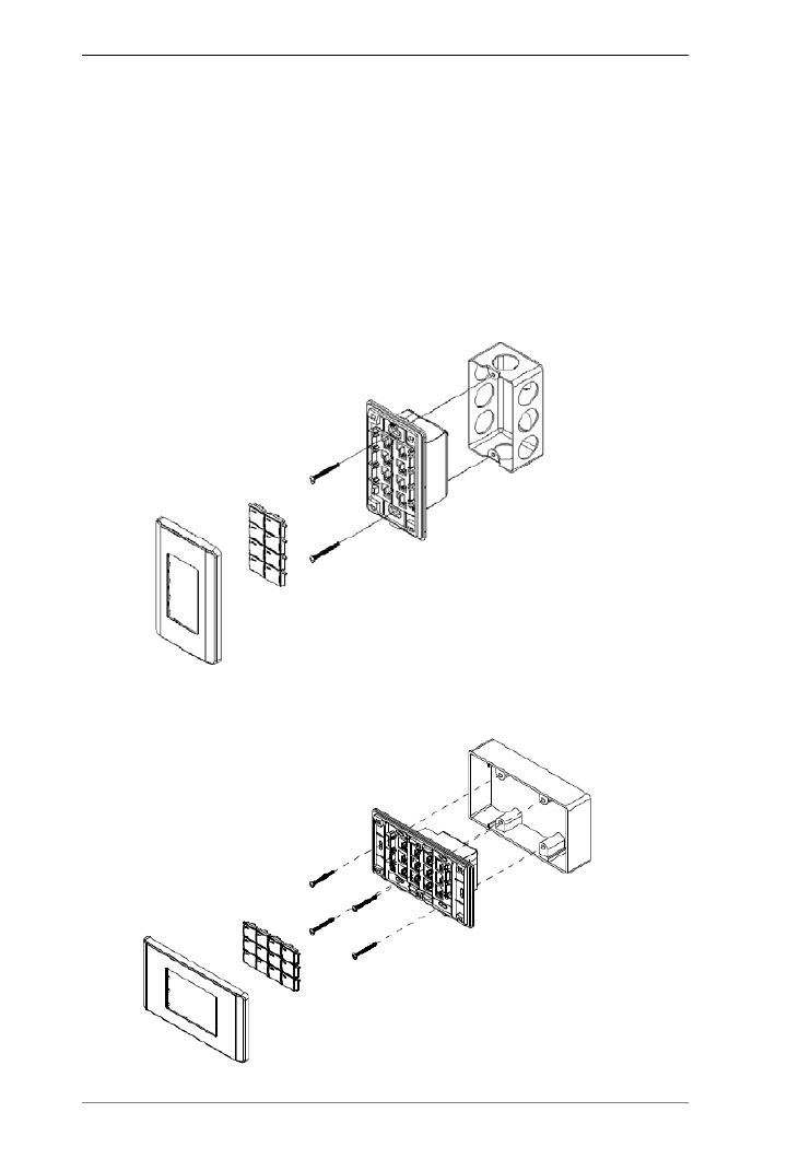
50
Installing ATEN Keypad
You can install the Keypad in a wall, podium, or desk. To install the Keypad,
follow the steps below:
1. Choose a location free of interference and prepare the installation site. You
can install the Keypad to a wall box or directly into the chosen surface.
Using a wall box
Use a wall box of appropriate size (2-gang for the VK112EU; 1-gang
for the VK108US) and depth (at least 6 cm, 2.36 inches).
VK108US
VK112 EU( )

Chapter 2. Hardware Setup
51
VK112 MK( )
Directly into the chosen surface
a) Refer to the Panel Mount Cutout diagram (VK112EU page2 59;
VK108US, page 263) to find out the length and width of the cutout area
and mark the opening on the chosen surface.
b) Cut out the marked area to a depth of at least 6 cm (2.36 inches).
2. Pair the Keypad with a Control Box by adjusting the Keypad ID Switch
(blue) to the ID number that the Control Box uses.
Note: One ATEN Control Box can work with up to 8 Keypads.
3. Supply the Keypad with power and network connectivity using one of the
following methods. The LAN LED light green to indicate that the Keypad
is supplied with power and successfully linked to the network.
To power the Keypad by PoE, use an Ethernet cable to connect the
Keypad to a PoE-enabled Ethernet switch.
If you do not have a power sourcing equipment, use an Ethernet cable
to connect the Keypad to LAN and a power adapter to supply power.
Purchase a power adapter for this installation.
Follow the steps below to prepare the power adapter and then plug
it to the Keypad.

Chapter 2. Hardware Setup
53
From the top row, attach each row of button caps to the Keypad
by pressing on the hinges.
Caution: When removing button caps, place your fingers on the top
of button caps and then press downwards, as illustrated below.
Pressing upwards from the bottom may cause damages to the button
caps.
c) Attach the faceplate to the Keypad.
IMPORTANT: After installing the Keypad, create a control interface
(Viewer) and upload the Viewer to the Control Box. For details, see Design,
page 100.

ATEN Control System User Manual
54
This Page Intentionally Left Blank

55
Chapter 3
Browser Operation
Overview
The ATEN controller can be configured over a standard TCP/IP connection via
its built-in Graphical User Interface (GUI). Because it can be accessed from
anywhere over a network or the Internet, operators can easily log in via a web
browser. The web interface can be used to upload licenses, set the access key,
enable monitors and update the firmware.
Logging In
To access the GUI, type the IP address of the controller into the address bar of
any browser. If a Security Alert dialog box appears, accept the certificate – it
can be trusted. The Welcome screen appears:
The default IP address is http://192.168.0.60
The default access key is: password
Only one user can log in at a time
Supports Internet Explorer browsers IE9 and higher
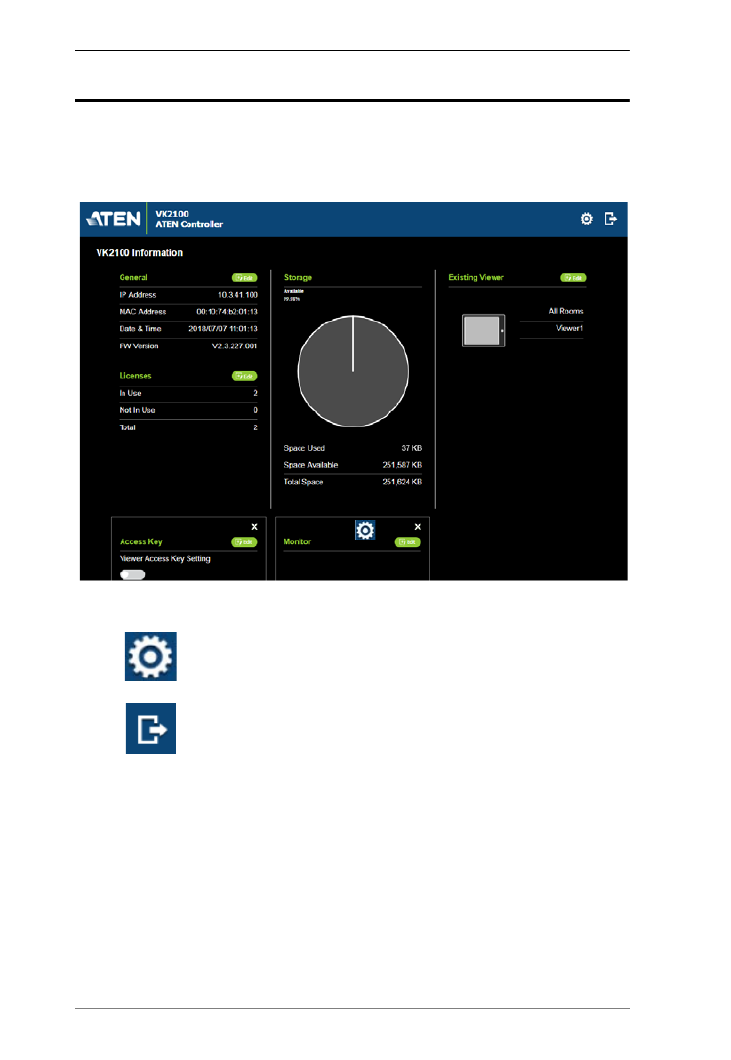
ATEN Control System User Manual
56
Dashboard
The Dashboard appears when you successfully log in to the Control Box. The
Dashboard gives a quick view of each setting and provides a link to each page.
Click Manage to configure the settings.
The top bar provides two options:
Click to enter the Settings page.
Click to log out of the web console.

Chapter 3. Browser Operation
57
Settings
The Settings view contains tabs to provide options to configure the controller.
The page is divided into two parts, the Interactive Display Panel which is
used to configure the options and the Top Bar which provides icons to exit the
settings page and log out of the web session.
The Settings page opens on the General tab, as shown below:
The General tab contains network, system time, and firmware upgrade settings.
Controller Info Provides network and identification information pertaining to the
controller.
Device Name: Sets the device name.
Controller ID: Displays the controller ID # set on the rear of the
unit.
IP Address: Provides the IP address of the controller.
MAC Address: Provides the hardware MAC address of the
controller.

ATEN Control System User Manual
58
Date & Time
Automatically
Time Zone: Select a time zone for the controller. Choose
the city that most closely corresponds to where it is located.
NTP Server Settings
Assign an NTP server for the controller to synchronizes its
clock. If the controller have access to the Internet, configure the
Preferred NTP Server and Alternate NTP Server settings. If
the controller is installed in a closed network, configure the
Preferred Customer Server IP and Alternate Customer
Server IP settings.
Preferred NTP Server: Select an NTP server to provide
synchronization services to the controller. Make sure to use
an NTP server that is located close to where the controller
is installed to minimize propagation delays.
Alternate NTP Server: Select an alternate NTP server to
which the controller connects when it is unable to connect
to the preferred NTP server.
Preferred Customer Server IP: Select this option to use a
private NTP server if the controller is installed in a closed
network.
Alternate Customer Server IP: Select this option to set up
a substitute server if the controller is unable to connect to
the preferred server.
Adjust Time: Sets the interval at which the controller
synchronizes its clock with the assigned NTP server.
Sync: Click this button to save your configuration and start
synchronizing its clock with the assigned NTP server.
Manually: Use the drop-down lists to set the controller’s time
zone, date, and time.
Firmware Displays the Current Firmware version and option to upgrade.
Click Update Firmware to open the window. Firmware Upgrade
Click Browse to select the firmware upgrade file.
When Check FW Version is selected, the system will check the
current firmware version against the one being used to upgrade the
controller. If the device version is higher than the upgrade version a
dialog box informs you and gives you the option to continue or
cancel.
After the file has been selected, click Update to start the firmware
upgrade.
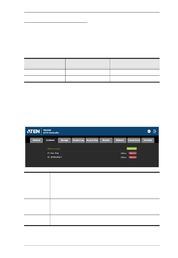
Chapter 3. Browser Operation
59
Licenses for Mobile Control
A license is a software permit that an ATEN controller grants to a mobile
device for remote control. If you have three licenses for a controller, you can
remotely operate the controller using three mobile devices at the same time.
Refer to the table below for the number of free licenses and the maximum
number of paid licenses each controller supports. To purchase additional
copies of license, contact your local sales representative.
You can use the Licenses tab to:
Find out the total number of licenses, the number of licenses that are
available, and those that are in use
Upload licenses to the ATEN controller
View license information
Licenses ATEN Control Box
(VK1100 / VK2100)
ATEN Control Pad
(VK0100 / VK0200)
No. of free licenses 2 0
Maximum no. of licenses 10 10
Licenses
In Use: displays the number of licenses being used by mobile
devices.
Not in Use: displays the number of licenses available for use.
Total shows the number of licenses purchased for the controller.
Update License Clicking Add opens the Add License window to upload new licenses to
the controller. Click Browse to locate the license file and Add to upload
the license(s).
Remove When a device is accessing the controller, you can click the Remove
button to disconnect the session.
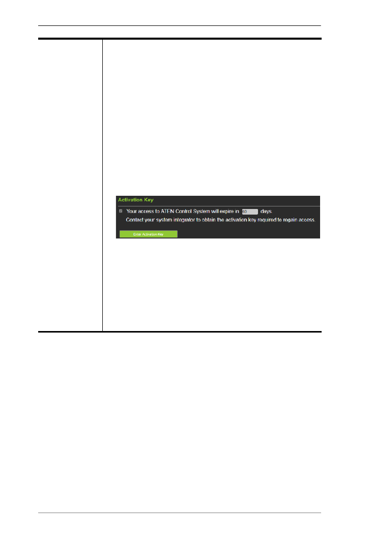
ATEN Control System User Manual
62
Activation Key The activation key is a string of letters and numbers used to assign
a validity period of accessing the ATEN Control System.
To set up a validity period for accessing the ATEN Control System:
1. Select Your access to ATEN Control System will expire in
and type the number of days.
2. Type an activation key. Follow the guidelines below when
creating your activation key:
Max number of characters: 32
Allowed characters: uppercase and lowercase letters,
numbers, and underscore
Max. number of days: 999 days
3. Type the activation key again to confirm.
4. Click Save. The limit is immediately applied. For example:
Note: Keep the activation key somewhere secure because it
cannot be recovered. In case you forget the activation key,
press the reset button/switch for 8 seconds to set the ATEN
controller to default. This will reset all configuration of the
controller to default and remove any projects and Viewers
stored on the ATEN controller.
To disable the validity period, click Enter Activation Key to type the
activation key provided by the system integrator.

Chapter 3. Browser Operation
63
Monitor
The Monitor tab allows you to view and enable the monitors that have been
configured for Flags and digital input devices in the VK6000 software. Check
the Show on dashboard box to show the Monitor settings on the Dashboard.
Click the slide bar next to the monitor you want to enable or use the drop-down
menu to select All On or All Off.
For more information about creating monitors, see Library, page 152.

ATEN Control System User Manual
64
Network
The Network tab allows you to view and configure the controller’s network
settings. Select Manually to set a static IP Address, Subnet Mask, and Default
Gateway, or Use DHCP to have the server assign an IP address to the
controller.
Note: Make sure to set the ATEN controller’s IP address and Default Gateway
to the same subnet.

Chapter 3. Browser Operation
65
Connections
The Connections tab allows you to view the connection statuses and IP
addresses of licensed devices, ATEN Keypads, and ATEN Expansion Boxes.
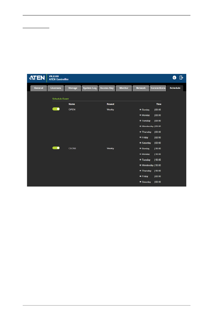
ATEN Control System User Manual
66
Schedule
The Schedule tab lists scheduled events predefined using the ATEN
Configurator. You can use this tab to do the following:
Enable or disable scheduled events.
Enable or disable scheduled days
For details on setting up scheduled events, see Scheduled Events, page 175.

Chapter 3. Browser Operation
67
Security
The Security tab allows you to secure the browsing sessions between your
computer and the ATEN controller’s web interface using SSL encryption.
Purchase and obtain an SSL certificate from a trusted certifying authority and
click Upload in this page to apply the certificate.

ATEN Control System User Manual
68
This Page Intentionally Left Blank

69
Chapter 4
ATEN Configurator (VK6000)
Overview
The ATEN Configurator (VK6000) is a GUI-based management tool that helps
you set up and configure the connected hardware and create control interfaces
to be used by mobile devices and ATEN Keypads.
Installation
To install the ATEN Configurator software, do the following:
1. Download ATEN Configurator.
a) Visit the ATEN download page.
http://www.aten.com/global/en/support-and-downloads/downloads/
b) Search for “VK6000”. A list of downloads for VK6000 appear.
c) Click ATEN_configurator_software_x.x.xxx.zip to download.
2. Open the downloaded zip file and double-click
ATEN_configurator_software_x.x.xxx.exe to run the setup. This screen
appears.
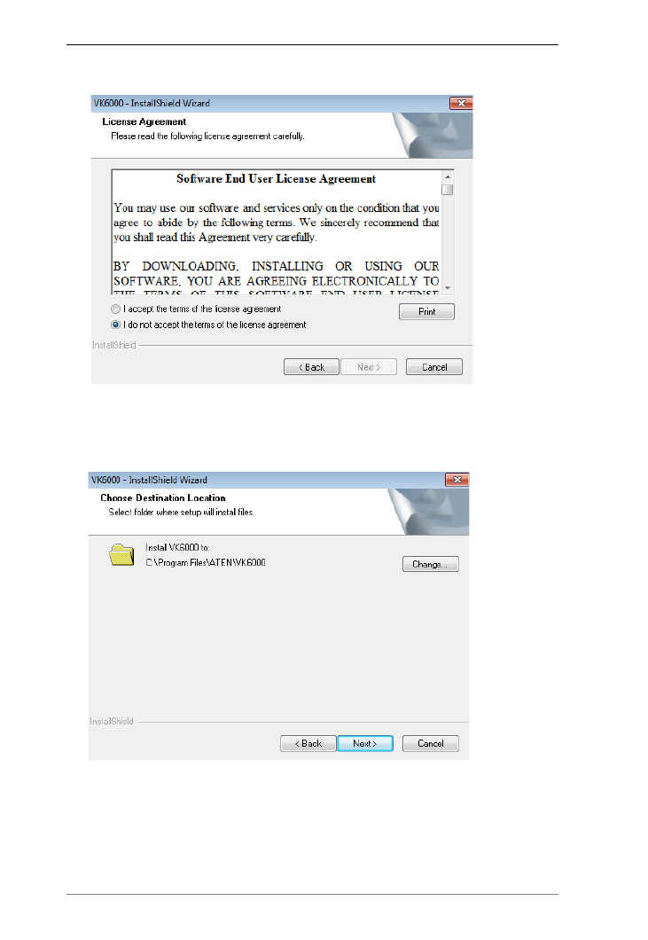
ATEN Control System User Manual
70
3. Click Next. This screen appears.
4. If you agree with the License Agreement, select I accept the terms of the
license agreement, and click Next. Click Print to print the Software End
User License Agreement. This screen appears.
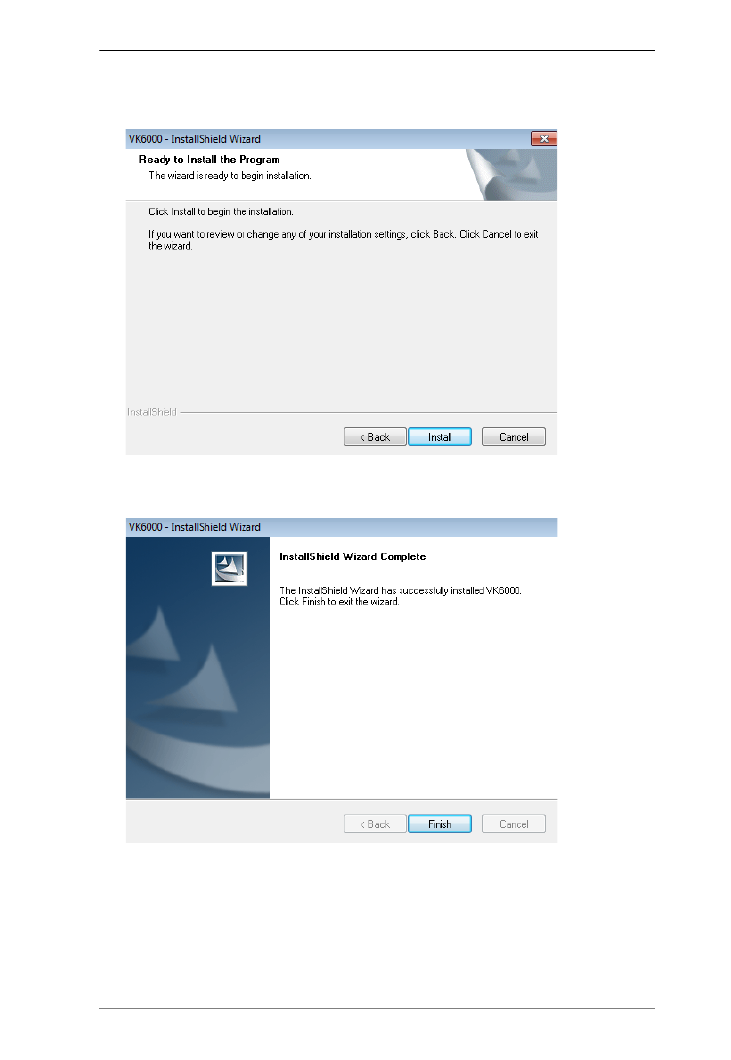
Chapter 4. ATEN Configurator (VK6000)
71
5. To change the destination location, click Change. Click Next to proceed
using the default location. This screen appears.
6. Click Install. When the process is complete, a confirmation message
appears.
7. Click Finish.

Chapter 4. ATEN Configurator (VK6000)
73
3. In the Design tab, do the following.
Create and configure a control interface (Viewer). For more
information, see Design, page 100.
(Optional) Set up scheduled events to automatically carry out specified
actions.
(Optional) Add additional conditions and actions to buttons using
Flags. For details, see Flag, page 153.
(Optional) Create a sequence of actions for a button by creating a
Macro. For details, see Macro, page 173.
(Optional) Create a Variable for a device setting that is controlled by
two or more components in one control interface. For details, see
Variables, page 176.
4. In the Upload tab, upload this Viewer to the controller. For details, see
Upload, page 182.
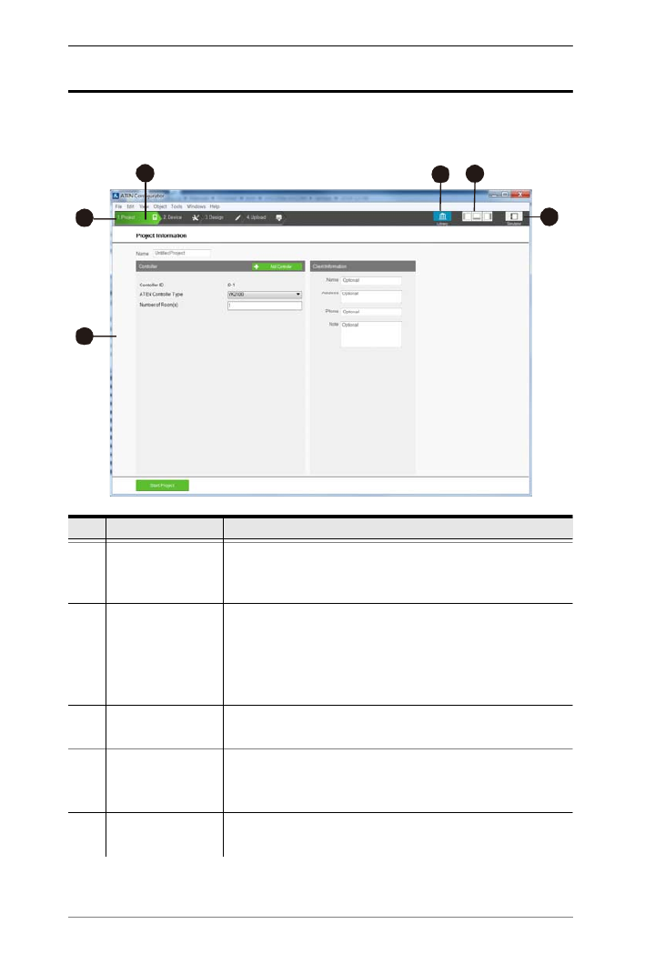
ATEN Control System User Manual
74
Main Page
Double-click the Configurator.exe shortcut to open the ATEN Configurator
software. The Project page appears:
No. Control Description
1 Menu bar The Menu Bar contains categories with options that pertain
to different sections of the software. Menu bar items are
listed on page 76.
2 Project Bar The Project Bar contains four tab and the Library icon. Each
tab relates to a step required to set up the project. Each
step and the Library can be selected by clicking on the bar.
Each step is discussed, starting on page 82, and the
Library on page 99.
3 Interactive Display
Panel
This is the main work area. The page that appears here
reflects the project tab that is selected.
4 Library The Library contains the devices, graphic, flag, macro, and
monitor databases. Each section allows you to add custom
items or choose from ready made selections.
5 Toggle Bar These three icons are used as a toggle to show or hide the
right, left and bottom control panel.
2
1
3
45
6

Chapter 4. ATEN Configurator (VK6000)
75
6 Simulator The Simulator button is used to test the Viewer after it is
created in Design. The simulator allows you to tryout the
interface as it would work on a mobile device but without
actually controlling devices. Use the mouse to click through
the page links.
No. Control Description

ATEN Control System User Manual
76
Menu Bar
Use the Menu Bar to select options in each project tab. The table below
provides a description of each menu item.
Menu Sub-Menu Description
File New Project Select to create a new project.
Open Project Select to browse and open a previously
saved project.
Restore Project from Controller Downloads a previously backed up
project from a controller.
Close Closes the current project and returns to
the Project tab.
Save Select to save changes to the current
project.
Save as Use this option to save the project as a
different name.
Export Viewer to USB
(Not supported by ATEN Control
Pad)
Exports Viewers and an access key to a
USB drive. After exporting the data onto
a USB drive, plug the USB drive into the
Control Box’s USB port to upload the
Viewer files and the access key. These
files can only be read by the Control Box
and are not project files that can be
opened by the ATEN Configurator
software.
Project Report Click to save a PDF file that contains
detailed information about each part of
the current project.
Import ETS Project Import an ETS project file for your KNX
devices.
Recent Projects Select to view a list of recent projects that
can be clicked on to open.
Exit Select to close the project and exit.

Chapter 4. ATEN Configurator (VK6000)
77
Edit Undo Select to undo a change when editing a
Viewer in Create & Design Viewer.
Redo Select to redo a change when editing a
Viewer page in Create & Design Viewer.
Cut/Copy/Paste Select to cut, copy or paste text and
objects when editing a Viewer page in
Create & Design Viewer. When used to
copy and paste a button, both the
General and Action properties are
copied.
Paste Graphic Only Select to paste a button’s image but not
its Action properties in Create & Design
Viewer.
Delete Select to delete highlighted text and
images when editing a page in Create &
Design Viewer.
Delete Action Only Select to delete the Action properties of a
button in Create & Design Viewer.
Select All / Deselect All Use either option to select or unselect all
objects when editing a viewer page in
Create & Design Viewer.
Preferences Display
Language
Use to select the language for the
interface.
SSH
Destination
Click to choose the location of the
executable for the SSH Client software.
To execute the program, go to the menu
bar and select Tools
→
SSH Client.
Interface Check a box to enable the feature
described below:
Show Welcome Page: displays the
Welcome screen when the ATEN Con-
figurator software opens.
Auto Page Creation: automatically
creates a Viewer page in Create
Viewer & Design, for every hardware
device that is configured in Select
Device & Configuration.
Show Password: displays the charac-
ters of the access key in the Edit
Access Key dialog box.
Automatically check for updates:
automatically checks for updates and
notify the user when an update is
available.
Menu Sub-Menu Description

Chapter 4. ATEN Configurator (VK6000)
79
Object PowerPoint Control Template Adds a PowerPoint Control template to
the Viewer. This control template is used
to control PowerPoint files saved in a
target computer.
Media Control Template Adds a Media Control template to the
Viewer. This control template is used to
control media files saved in a target
computer.
Line Adds a line to visually separate objects
on the Viewer.
Frame Adds a frame to visually frame an object
or to group a set of objects in the Viewer.
Dial Kit Adds a dial kit to the Viewer. The dial kit
can be used for dialing a meeting.
Group Group Select multiple objects and use Group to
lock them together. Objects in the group
will move together as one.
Radio
Group
Select multiple buttons and use Radio
Group to associate them as follows:
selecting a button that belongs to the
radio group deselects the previously
selected radio button within the same
group.
Ungroup Select grouped objects and use
Ungroup to unlock the group.
Order Bring to
Front
Moves an object to the top position when
objects are layered.
Send to
Back
Moves an object to the bottom position
when objects are layered.
Bring
Forward
Moves an object up one position when
objects are layered.
Send
Backward
Moves an object down one position when
objects are layered.
Menu Sub-Menu Description

ATEN Control System User Manual
80
Object Align Left Aligns two or more selected objects to
the Left side of the object that is selected
last.
Center Aligns two or more selected objects to
the horizontal position of the object that
is selected last.
Right Aligns two or more selected objects to
the Right side of the object that is
selected last.
Top Aligns two or more selected objects to
the Top side of the object that is selected
last.
Middle Aligns two or more selected objects to
the vertical position of the object that is
selected last.
Bottom Aligns two or more selected objects to
the Bottom side of the object that is
selected last.
Make Same Size Width Resizes two or more selected objects to
the same width of the object that is
selected last.
Height Resizes two or more selected objects to
the same height of the object that is
selected last.
Both Resizes two or more selected objects to
the same width and height of the object
that is selected last.
Space Evenly Across
Page Width
Spaces two or more selected objects
evenly across the width of the page.
Across
Page
Height
Spaces two or more selected objects
evenly across the height of the page.
Between
Objects
Horizontally
Adjusts the horizontal space between
three or more selected objects to the
average distance between each of the
selected objects.
Between
Objects
Vertically
Adjusts the vertical space between three
or more selected objects to the average
distance between each of the selected
objects.
Menu Sub-Menu Description

Chapter 4. ATEN Configurator (VK6000)
81
Tools Database Generator Opens the ATEN Database Generator
which is used to manually add and
configure hardware devices. This is
where you can create custom devices to
add to My Device Library. See ATEN
Database Generator, page 185, for
details.
Simulator The Simulator is used to test a Viewer’s
interface after it has been created in
Design. The simulator allows you to
tryout the interface as it would work on a
mobile device but without actually
controlling devices. Use the mouse to
click through the page links.
SSH Client This runs the SSH Client software
selected under Edit
→
Preferences
→
SSH Destination. The SSH Client is used
to communicate with the controller.
Windows New Page Click to create a new Viewer page or
select a page to open in Create Viewer &
Design.
Help About Provides the firmware version and
support information for the Configurator
software.
Check for Updates Checks if ATEN Configurator is up-to-
date.
Menu Sub-Menu Description
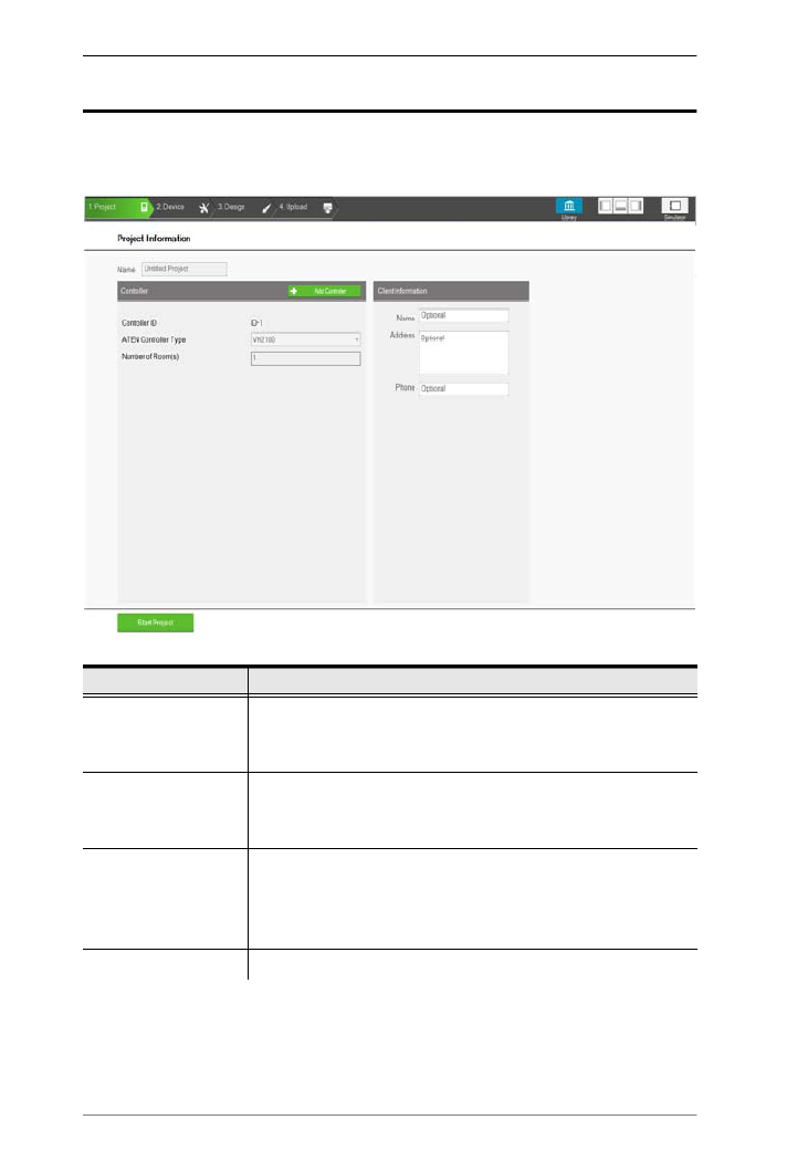
ATEN Control System User Manual
82
Project
The Project tab allows you to enter details about the installation to start the
project. Enter the information using the table below as a guide.
Control Description
Name Enter the project name you are setting up. You can create
multiple projects but for most installations only one project is
required.
Add Controller Click to add controllers to the project. The number added
should match the number of controllers installed. A project can
have up to 16 controllers.
Controller ID Displays the Control Box ID. Make sure to set the Control Box
ID Switch on the rear of the Control Box using the ID displayed
here so that the project file will be uploaded to the controller set
with the same ID.
ATEN Controller Type Select the controller model you are installing.

Chapter 4. ATEN Configurator (VK6000)
83
Number of Rooms Enter the number of rooms each controller will control. Each
hardware device you add will be associated with a room. When
buttons are configured in the Design tab, you can select a
Room under Button Action to filter the Device list so that only
hardware in that room appears. This link between the
controller, devices and room is how the Viewer knows which
devices to control.
Name Enter the client name associated with the project.
Address Enter the client address associated with the project.
Phone Enter the client phone number associated with the project.
Remove Controller Click to delete a controller from the project.
Start Project Click to begin configuring hardware devices. The Select Device
& Configuration tab will open.
Control Description
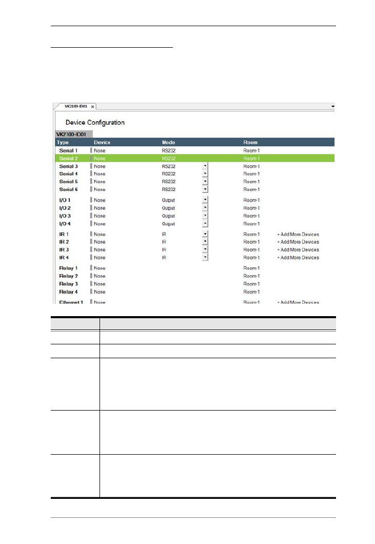
Chapter 4. ATEN Configurator (VK6000)
85
Device Configuration List
The Device Configuration page lists the controller ports by type. Click a port
to view its Properties (page 88). Double-click a port to open the ATEN
Device Library and search for the hardware device to configure the port.
Configure each port according to the hardware device connected to it.
Control Description
Type Lists the ports of the controller.
Device Lists the device name entered in Properties.
Mode Lists the port’s communication mode. Click an arrow to select options:
Serial: RS232, RS422, or RS485
I/O: Input (VDC), Input (Dry Contact) or Output
IR: IR or RS232
Room Lists the room selected for a device. The rooms available depend on the
number of rooms added to the controller. No drop-down menu appears
if there is only one room. Each controller must have at least one room.
Select the room where the device is installed.
+ Add More
Devices
RS422, RS485, LAN and IR ports can cascade additional devices that
are connected to the first unit. IR ports can cascade 1 device, RS422
and RS485 ports can cascade up to 2 devices and LAN ports can
cascade up to 25 devices.
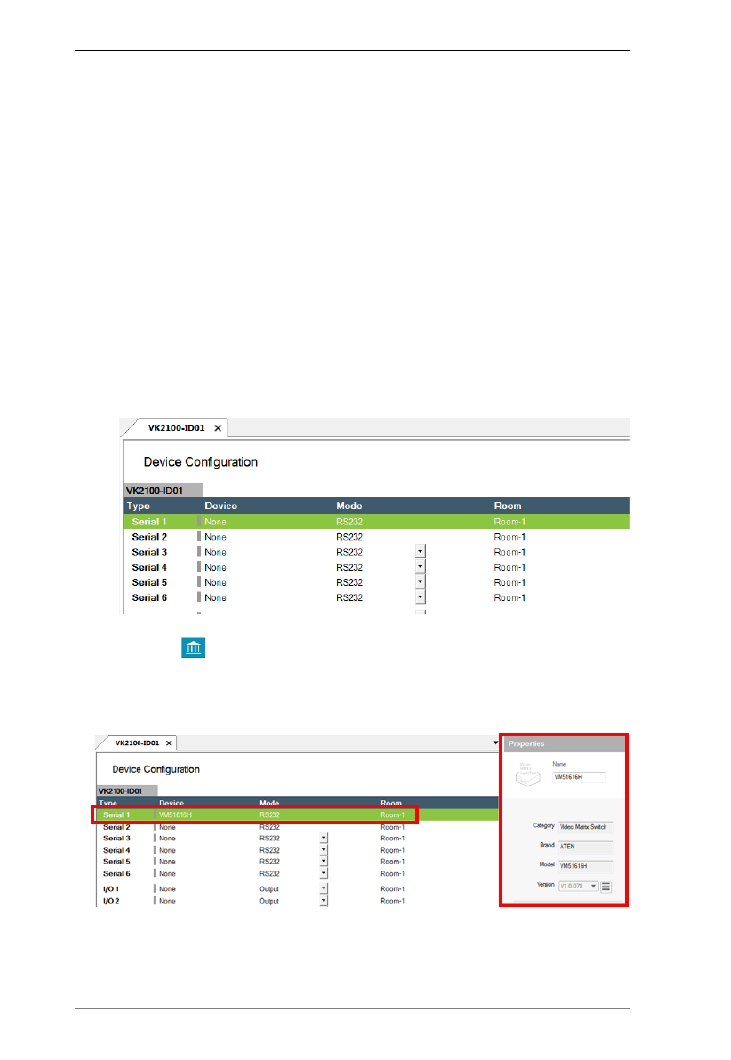
ATEN Control System User Manual
86
Adding Devices to ATEN Configurator
Add the devices to be managed by your ATEN controller to the Device
Configuration list and configure their settings.
To add KNX devices, follow the steps below:
1. Click File and then Import ETS Project. The configurations for your
KNX devices appear in the Controller tab on the left-side bar.
2. In the Controller tab, click on KNX IP Interface and type its IP address
and port in the Properties column.
To add devices that are not KNX compliant, use one of the following
methods:
Add devices using ATEN Device Library or My Library
1. In the Device Configuration list, click a port where you have
physically installed a device.
2. Click library. In the pop-up window, click the drop-down list to
select ATEN Device Library or My Library, and then double-click an
item to add a device. The selected device is added to Device
Configuration.

Chapter 4. ATEN Configurator (VK6000)
87
Add devices using the Properties column
Type the name of the device in Properties, and then click Add Device.
Note:If the device is not in the Library, create the device using Database
Generator. For details, see Edit / Add New Device, page 189.
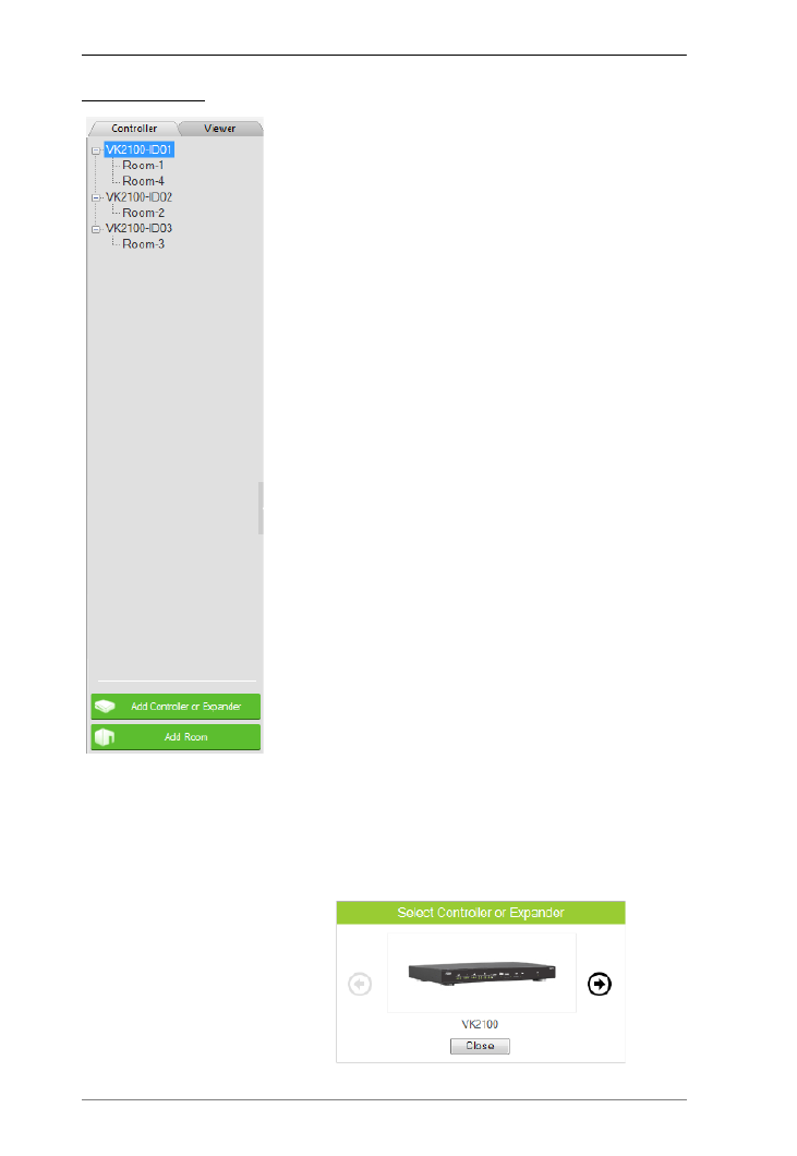
ATEN Control System User Manual
88
Left Sidebar
Controller
The Left Sidebar provides a tree view of the
controllers, Expansion Boxes, and rooms. Each
controller in the tree view represents a controller with
one or more rooms it manages. Selecting a controller
allows you to configure its ports. When a port is
configured for a device, it appears listed under the
Room.
Each controller must have at least one room. When
installing multiple controllers in one room, add a room
with the same name to each controller.
Each controller name ends with an ID number:
VK2100-ID01. Use this number to set the Controller
ID Switch on the rear of the controller. This links the
controller in the software to the physical device being
installed.
Right-click a controller to Add Room or Delete
Controller.
Room
Each room is associated with a controller and a
Viewer so that the information is uploaded to the
correct controller to control the hardware devices.
Right click a room to Delete or Rename the room.
Use the buttons at the bottom of the sidebar to Add
Room.
Expansion Box
ATEN Expansion Boxes connect over a network to
add ports to the controller via its Ethernet port.
Clicking Add Controller or Expander opens a
window which allows you to select a device to add:

Chapter 4. ATEN Configurator (VK6000)
89
Properties
The Properties panel provides information and configuration fields for
controllers, Expansion Boxes, remote devices, or rooms. Click a device or room
from the left sidebar or the Device Configuration list to display its properties.
Controller Properties
Click a controller from the left sidebar or the
Device Configuration list to configure the
following properties.
Name: Type to change the device name.
Controller ID: Sets the controller ID.
ATEN Expansion Box and Keypad will
connect to a controller with a matching
controller ID as set on the Expansion Box
or Keypad using the Controller ID Switch.
Identify ATEN Expansion Box and Keypad by IP Address:
Note: Only enable this function if any of the following scenario applies.
Need to install more than 16 controllers under the same subnet.
Your network switch blocks multicast signals between the controller and
Expansion Box/Keypad.
When enabled, the controller connects to an ATEN Expansion Box/Keypad
with matching controller ID and Expansion Box/Keypad IP address.
To use this function, make sure to do the following.
On the Expansion Box/Keypad:
Set the controller ID using the Controller ID Switch. When you
have more than 16 controllers under a subnet, at least two of the
Expansion Boxes and/or Keypads will be assigned with the same
controller ID.
Set the Expansion Box/Keypad to a fixed IP address.
In the project files:
In the Devices tab, make sure the controller IDs match the
configuration on the Expansion Boxes and/or Keypads.
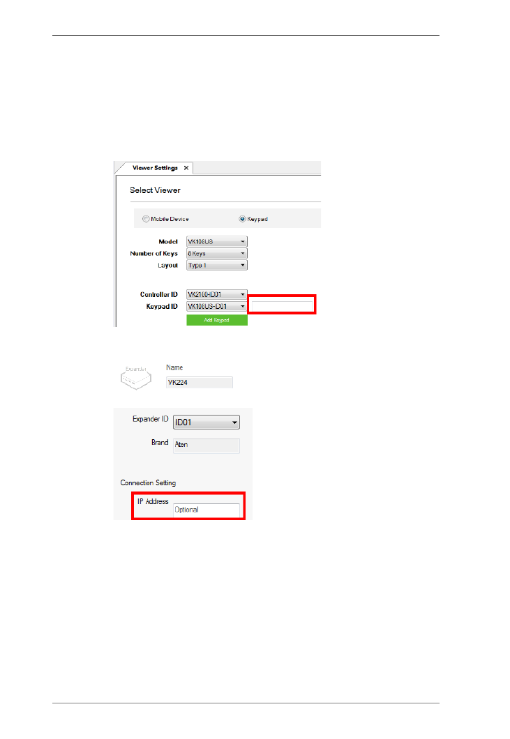
ATEN Control System User Manual
90
In the Devices tab, enable the Identify ATEN Expansion Boxes
and Keypads by IP address function the Properties panel. For
example, if you have 17 controllers set up under the same subnet,
with controller 1 and 17 using ID01, enable the function for both of
these controllers.
Specify the IP address of the Expansion Box/Keypad.
sdfFor Keypad, go to Design > Viewer Settings.
s
dfFor Expansion Box, go to Devices and find the Properties panel.
Port: Specify the port to allow TCP communications from third-party client
devices.
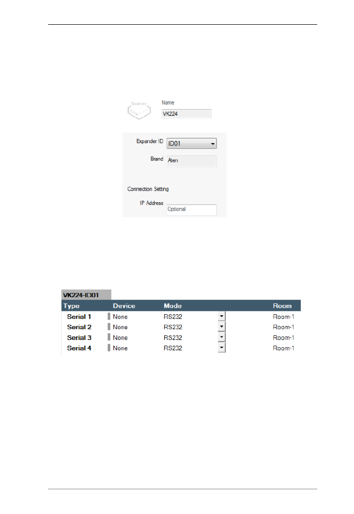
Chapter 4. ATEN Configurator (VK6000)
91
Expansion Box (Expander)
When you select an Expansion Box from the left side bar, the properties
provides a drop-down menu to set the Expander ID (ID01~ID08) and the option
to configure the IP Address.
To add an Expansion Box, click Add Controller or Expander on the left
sidebar, then use the arrow and select an ATEN Expansion Box to add. The
expansion box and ports will be listed on the Device Configuration page, as
shown below:
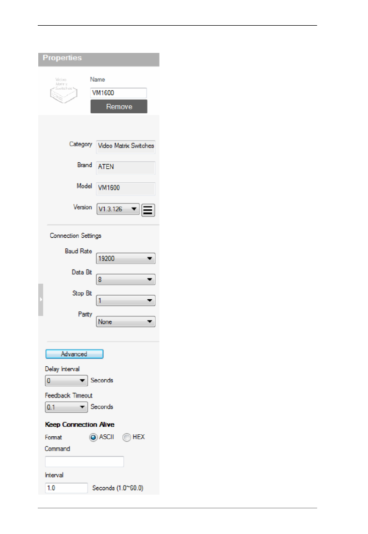
ATEN Control System User Manual
92
Serial Device Properties
Click a serial device from the Device
Configuration list to configure its
properties.
Name: Type to set the device name.
Add Device: Adds devices. You can use
either of the following methods to add
devices:
Type the device name in the Name field
and click Add Device.
Click the arrow button (following the Add
Device button) and select add device
from library to open the device library.
Double-click a device to bring in its
information and settings.
Category: Displays the category of the
selected device.
Brand: Displays the brand of the
selected device.
Model: Displays the model of the
selected device.
Version: Shows the firmware version
selected for the device. Use the drop-
down menu to select a different firmware
version. Click the menu box next to the
version number to open a PDF with the
version history. The version history and
different versions for a device can be
manually added/updated via the Database
Generator (see step 3 of Edit / Add New
Device, page 189).
Connection Settings: Click the drop-
down lists to configure the baud rate, data
bit, stop bit, parity settings, and flow
control for the selected serial device.
Advance Settings: Click Advanced to
display the following settings.

Chapter 4. ATEN Configurator (VK6000)
93
Delay Interval: Sets a time delay for each command before they are
sent to the device.
Feedback Timeout: Sets the maximum interval that the controller
allows in between parts of a feedback message. The controller uses
this value to identify the end of a message.
Keep Connection Alive: The controller sends a command to the serial
device to maintain the connection and avoid timeout issues.
Command: Type a command to be sent to the selected device.
Interval: Type the interval at which the controller sends the
command.
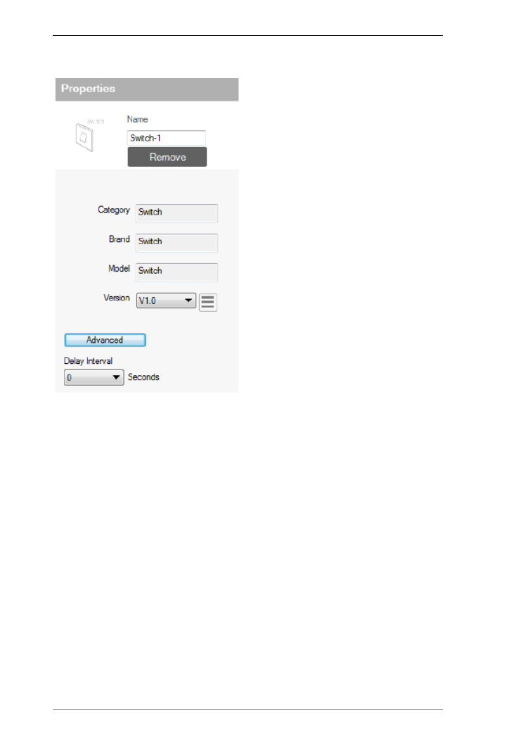
ATEN Control System User Manual
94
I/O Device Properties
Click an I/O device from the Device
Configuration list and select Input
(VDC), Input (Dry Contact), or Output
to configure its properties.
Name: Type to set the device name.
Add Device: Adds devices. You can
use either of the following methods to
add devices:
Type the device name in the Name
field and click Add Device.
Click the arrow button (following the
Add Device button) and select add
device from library to open the device
library. Double-click a device to bring in
its information and settings.
Category: Displays the category of
the selected device.
Brand: Displays the brand of the
selected device.
Model: Displays the model of the
selected device.
Version: Shows the firmware version selected for the device. Use the drop-
down menu to select a different firmware version. Click the menu box next
to the version number to open a PDF with the version history. The version
history and different versions for a device can be manually added/updated
via the Database Generator (see step 3 of Edit / Add New Device,
page 189).
Lower Threshold & Upper Threshold: Set the thresholds according to the
hardware device you are connecting and then configure a Monitor (see
page 155).
Advance Settings: Click Advanced to display the Delay Interval setting.
Delay Interval: Sets a time delay for each command before they are
sent to the device.
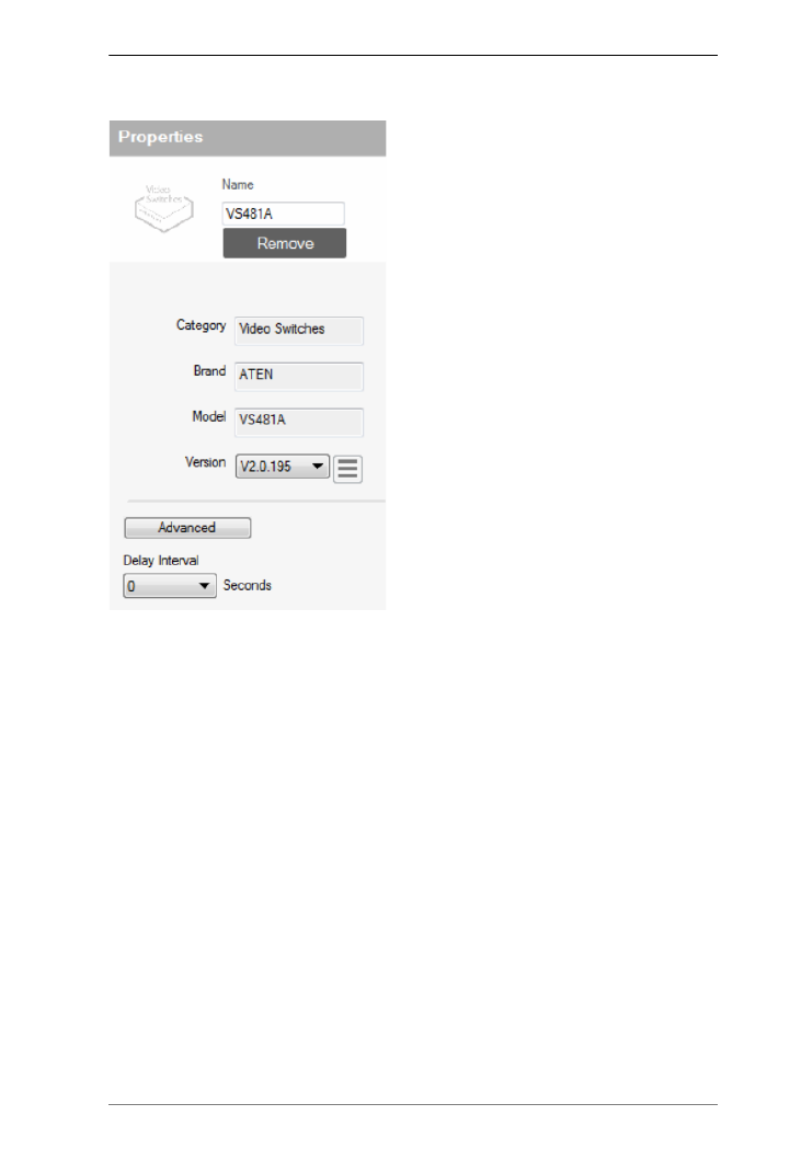
Chapter 4. ATEN Configurator (VK6000)
95
IR/Relay Device Properties
Click an IR/Relay device from the Device
Configuration list to configure its
properties.
Name: Type to set the device name.
Add Device: Adds devices. You can
use either of the following methods to
add devices:
Type the device name in the Name field
and click Add Device.
Click the arrow button (following the
Add Device button) and select add
device from library to open the device
library. Double-click a device to bring in
its information and settings.
Category: Displays the category of the
selected device.
Brand: Displays the brand of the
selected device.
Model: Displays the model of the
selected device.
Version: Shows the firmware version selected for the device. Use the drop-
down menu to select a different firmware version. Click the menu box next
to the version number to open a PDF with the version history. The version
history and different versions for a device can be manually added/updated
via the Database Generator (see step 3 of Edit / Add New Device,
page 189).
Advance Settings: Click Advanced to display the Delay Interval setting.
Delay Interval: Sets a time delay for each command before they are
sent to the device.

ATEN Control System User Manual
96
Ethernet Device Properties
Click an Ethernet device to configure its
properties. Each Control Box supports up
to 25 Ethernet devices, and each Control
Pad supports up to 8.
Name: Type to set the device name.
Add Device: Adds devices. You can
use either of the following methods to
add devices:
Type the device name in the Name field
and click Add Device.
Click the arrow button (following the
Add Device button) and select add
device from library to open the device
library. Double-click a device to bring in
its information and settings.
Category: Displays the category of the
selected device.
Brand: Displays the brand of the
selected device.
Model: Displays the model of the
selected device.
Version: Shows the firmware version
selected for the device. Use the drop-
down menu to select a different firmware
version. Click the menu box next to the
version number to open a PDF with the
version history. The version history and
different versions for a device can be
manually added/updated via the
Database Generator (see step 3 of Edit /
Add New Device, page 189).
Connection Settings
Depending on the selected protocol, some of the following settings may not
be required and are not displayed.
Protocol Type: Click to select the protocol for the Ethernet device. The
ATEN Control System supports control of devices via telnet, ONVIF,
TCP, UDP, HTTP, and HTTPS.
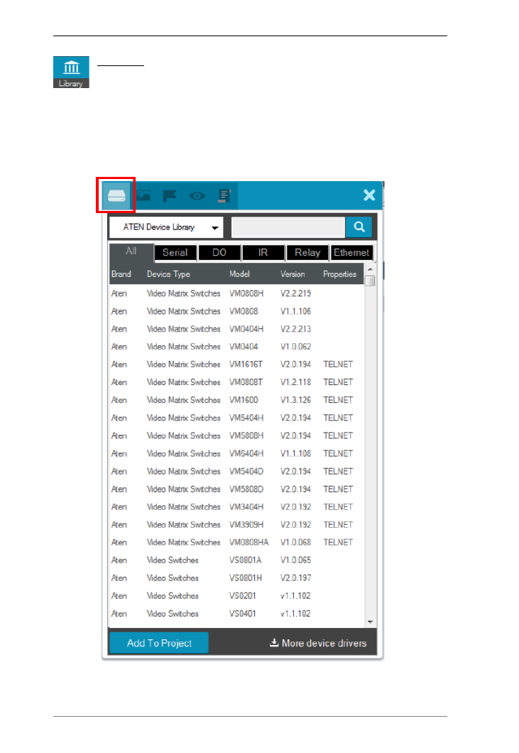
ATEN Control System User Manual
98
Library
The Project Bar provides the Library option. Use the Device Library
tab (shown below) to configure controller ports according to the
connected hardware devices. The Device Library provides an extensive
database of hardware devices that can be double-clicked or drag and dropped
into the Device Configuration page to configure controller ports. The Device
Library is discussed on the next page.

Chapter 4. ATEN Configurator (VK6000)
99
Device Library
The Device Library tab is a database of hardware devices that instantly
configure controller ports. Search the library for the device connected
to a controller port then add it to configure the port. For devices not in the
library, use the ATEN Database Generator to create custom hardware (see
page 185). Click Library on the Project bar or double-click a port on the
Device Configuration page to open the ATEN Device Library.
Add a device by clicking Add to Project or by drag & drop.
To search for a device type keywords into the box and click .
Click a tab to filter by All, Serial, DO, IR, Relay or Ethernet.
Click headings to sort by Brand, Device Type, Model or Version.
Use the drop-down menu to select:
ATEN Device Library – ATEN’s database of hardware devices.
My Device Library – Devices added from the Database Generator.
Create Device – Opens the Database Generator to create custom
hardware devices for My Device Library (
page 186
).

Chapter 4. ATEN Configurator (VK6000)
101
Left Sidebar
Viewer
The Left Sidebar provides a tree view of the
Viewers and Pages. Clicking a Viewer opens the
Page Overview which is a layout of the Viewer.
Right-click a Viewer to Delete, Rename or Edit the
Viewer.
Use Add Viewer at the bottom of the sidebar to
create a new Viewer.
Pages
Each Viewer lists the Home Page with each
Viewer Page created for the Viewer under it.
Clicking a Home or Viewer Page on the sidebar
opens a new tab where the page can be edited.
Right-click a page to Delete, Rename, or Copy the
page and paste it to another Viewer within the
same or a different project file. The Copy function
replicates the page’s visual design without its
configurations.
The Home Page cannot be deleted.
Use Add Page at the bottom of the sidebar to add
a page to the Viewer.
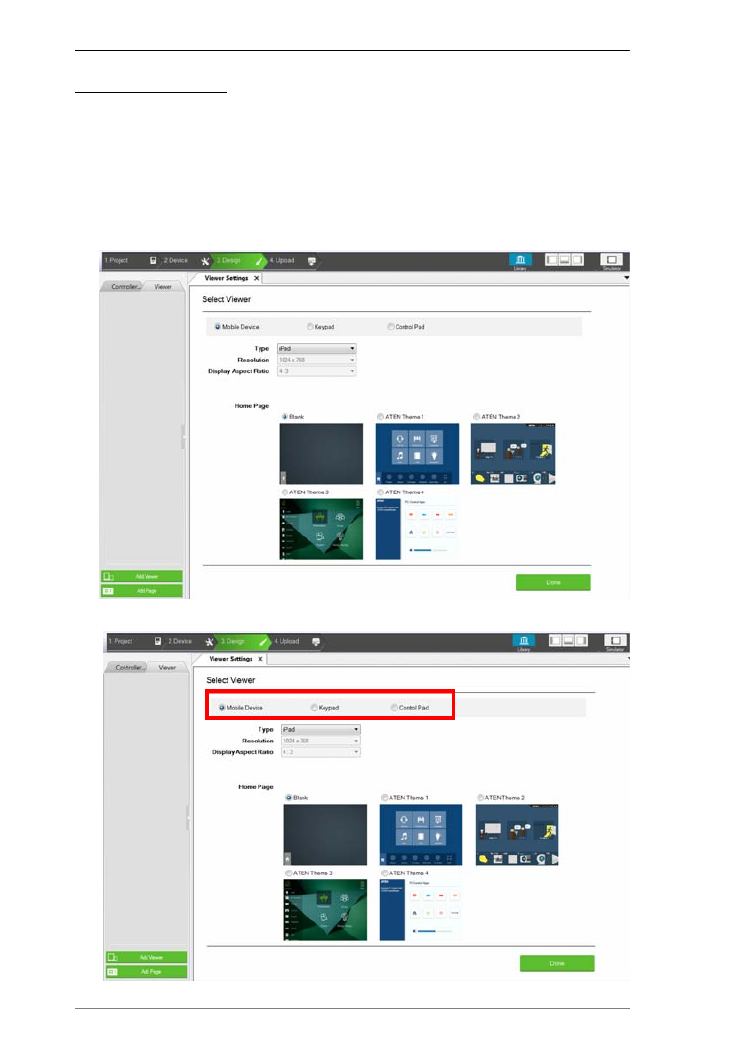
ATEN Control System User Manual
102
Adding a Viewer
A Viewer is a control interface that you use on mobile devices, ATEN
Keypads, or ATEN Control Pads to centrally control devices and equipment.
Use the Select Viewer page to select a Viewer template for your device type.
To add a Viewer and/or its associated control pages, follow the steps below.
1. In the Configurator, go to the Design tab. This screen appears. If the Select
View page does not appear, click Add Viewer from the left sidebar.
2. Select your device type.
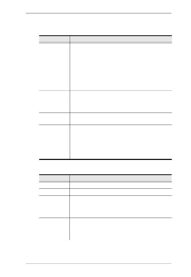
Chapter 4. ATEN Configurator (VK6000)
103
3. Configure the displayed settings for your selected device.
Mobile Device
Keypad
Setting Description
Type Use this drop-down menu to select the mobile device that
will be used to control hardware devices in a room. This sets
the resolution for the Viewer to fit on the mobile device’s
screen.
Choose a Custom selection to configure a screen size with
the Resolution drop-down menu below it.
Note: If you select Custom Windows Device – the Windows
OS has a limitation for adding buttons to Viewers used on
Windows mobile devices. See , page 241, for details.
Resolution Use this drop-down menu to set a custom screen resolution
for the mobile device being used to control hardware
devices. This option becomes available when you select one
of the Custom selections from the Type drop-down menu.
Display Aspect
Ratio
Indicates the aspect ratio used for the selected device.
Home Page Select a template for the Viewer’s home page.
Blank: Creates a custom home page that you design from
scratch.
ATEN Themes: Select any of the ATEN Themes to create
a home page and other device pages with graphics.
These pages are customizable.
Setting Description
Model Specify the Keypad model.
Number of Keys Specify the total number of keys for your Keypad.
Layout Specify the Keypad layout. This setting should match the
physical Keypad layout (see page 49 for details). Depending
on the total number of keys the Keypad has, you may have 1
or multiple options for this setting.
Controller ID Select the ID number of the Control Box (Controller) that the
Keypad will connect through. This ID must match the
controller ID Switch (black) set on the Keypad (see
page 53).

ATEN Control System User Manual
104
Control Pad
Keypad ID
Select the ID number to match the Keypad ID Switch
(blue) set on the Keypad (see page 53). Up to 8
Keypads can connect to one Control Box.
(Optional) Type the IP address of the Keypad with which
the controller uses to identify and establish connection.
Use this feature when you have more than 16 ATEN
Expansion Box and/or ATEN Keypad in the project or
when the network switch blocks multicast signals
between the Keypad and the controller.
Add Keypad Click Add Keypad to add another Keypad that will connect
to the same Control Box and control the same set of
devices.
Setting Description
Model Specify the model for the Control Pad.
Number of Keys Specify the total number of keys for your Control Pad.
Layout Specify the layout for the Control Pad. This setting should
match the physical layout (see page 49 for details).
Depending on the total number of keys the Control Pad has,
you may have 1 or multiple options for this setting.
Controller ID Displays the Control Pad ID.
Setting Description
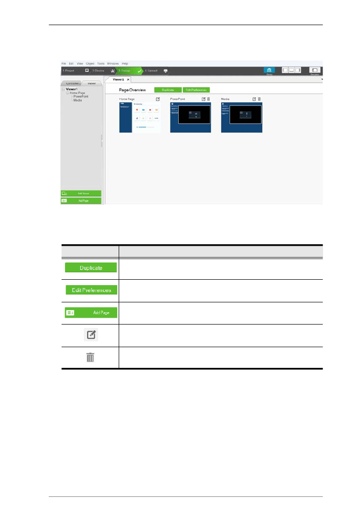
Chapter 4. ATEN Configurator (VK6000)
105
4. Click Done to save the configuration. An overview appears showing all
the control pages that the selected Viewer has.
5. (Optional) Add, edit, or remove the pages or adjust the basic settings of the
Viewer.
Control Description
Click to duplicate the Viewer along with the pages.
Click to edit the basic Viewer settings that you configured in step
3.
Click to add a page to the highlighted Viewer in the left sidebar.
Click to configure the page. For more information, see
Configuring the Viewer, page 106.
Click to remove the page.

Chapter 4. ATEN Configurator (VK6000)
107
3. Click the element in the preview panel to customize the settings. See the
table below for more information.
Element Tasks
Preview panel Shows a preview of the selected page. You can also do
the following on the preview panel:
To zoom in and out on the preview, scroll the
mouse wheel.
To relocate an object, drag and drop the object.
To layer an object, right-click the object and set
the Order options.
To group multiple objects, drag the mouse to
select the objects, right-click on any of the objects
and select Group.
To align object, drag the mouse to select the
objects, right-click on any of the objects and select
Align.
To set objects in perfect alignment, use the View
menu options to select Show Grid and Align to
Grid.

ATEN Control System User Manual
108
Properties panel Use the panel to configure selected object properties.
For detailed information about object properties, see
Object Properties, page 109.
Library Use Library to customize the appearance of the page
and its buttons. For more information, see Library,
page 98.
Button Action or
Slider Bar Action
Use this panel to define the functions of each button
and slider bar. For detailed information, see Button /
Slider Bar / Dial Kit Actions, page 127.
Advanced
functions
To add additional conditions and actions to
buttons, use the Flag function. For more
information, see Flag, page 153.
For a button to initiate a sequence of actions,
create a Macro. For more information, see Macro,
page 173.
Element Tasks

Chapter 4. ATEN Configurator (VK6000)
109
Object Properties
This section provides detailed information about properties of control objects
on the Viewer. Note that the supported objects and their functions may differ
among Viewers for mobile devices, Keypad, and Control Pad.
Page Objects
A number appears at the top right corner of each object. The numbers are
assigned in sequence, in the order that the object is added. These numbers help
identify a label when configuring a Change Label (page 144) or a button when
configuring a Change Button State (page 143).
Each button has a symbol in the top left corner to indicate:
“ ”A the button’s actions are configured correctly.
“!” the button’s actions need to be modified or they will not work.
Buttons with no symbol indicate that functions have not been added to it.
For details on adding functions, see Button / Slider Bar / Dial Kit Actions,
page 127.
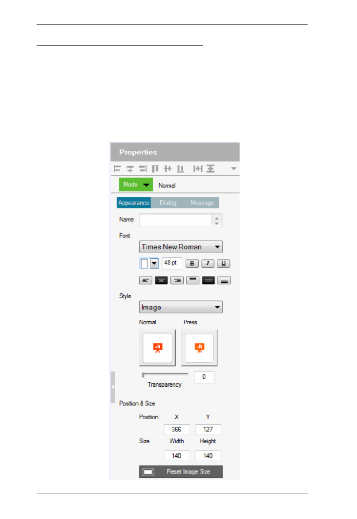
ATEN Control System User Manual
110
Object Properties for Mobile Devices
After you have added a Viewer (page 102) for your mobile device, you can
start configuring the pages that the Viewer contains in the Properties panel.
Buttons
The Button properties provide options to configure the appearance of a button,
and the confirmation message and progress message before carrying out the
associated action.

ATEN Control System User Manual
112
Alignment – click a box to align the text Right, Center or Left;
and Top, Middle or Bottom within the button box.
Style – use the drop-down menu to select the style type.
Normal imports an image to use as the button’s standard
background and click Pressed to import an image to use when the
button is pressed.
Color allows you to use drop-down menus to select the buttons
color for Normal and Pressed.
Transparency – enter a number (0-100) or use the slider-bar to
set the transparency of the button.
Send Command Every (Long Press mode buttons only) – use the
drop-down menu to select the amount of time between each command
that is sent (repeatedly) to the device while the button is pressed.
Position and Size – X Y and position the button at the coordinates
entered. Width and Height set the size of the button box. Click Reset
Image Size to reset the button size.
Reset Image Size – click to reset the button size.
Set Sync Condition – automatically synchronizes the button
setting to the selected variable. To create variables, see Variables,
page 176.
Restrict access to this button on ATEN Control System App with a
password: Limit the use of the selected button by requesting a
password when the button is tapped in the Viewer. To enable this
function, click this option and type the password in the box below.
Note: This function is only supported by the Normal and Toggle mode
buttons (page 111).
Dialog
Click the Dialog tab to set up a confirmation message that displays in the
Viewer when the button is pressed.
Note: The Dialog settings are only available for Normal and Toggle
buttons.
Confirm the associated action with the following message when the
button is pressed – Click the check box to enable this feature.
Action – Select a button action (Toggle On or Toggle Off) to display
the confirmation message.
Content drop-down list – Select one of the following for
customization.

Chapter 4. ATEN Configurator (VK6000)
113
Background – Customize the wording for the confirmation
message. Type the message in the Name field and optionally
customize its font and style.
OK – Customize the wording on the button for carrying out the
associated action. Type in the Name field and optionally
customize its font and style.
Cancel – Customize the wording on the button for canceling the
associated action. Type in the Name field and optionally
customize its font and style.
Message
Click the Message tab to set up a progress message that displays while the
associated action is being carried out.
Note: The Message settings are only available for Normal and Toggle
buttons.
Confirm the associated action with the following message when the
button is pressed – Click the check box to enable this feature.
Action – Select a button action (Toggle On or Toggle Off) for
displaying the progress message.
Content drop-down list – Select one of the following for
customization.
Background – Configure the wording for the progress message.
Type the message in the Name field and optionally customize its
font and style.
Progress Bar – Configure the display duration (in seconds), font,
and color of the progress indicator.

ATEN Control System User Manual
114
Groups
You can unify the properties of two or more control components (buttons,
slider bars, etc.) at the same time. Depending on the elements that your group
of components have, different properties will be open for configuration.Use
your mouse to drag and select the components from a page, the properties that
are open for configuration appear in the Properties column.
For example, if you want to unify the text that appear on multiple buttons, drag
and select these buttons and then configure their properties, as illustrated
below.
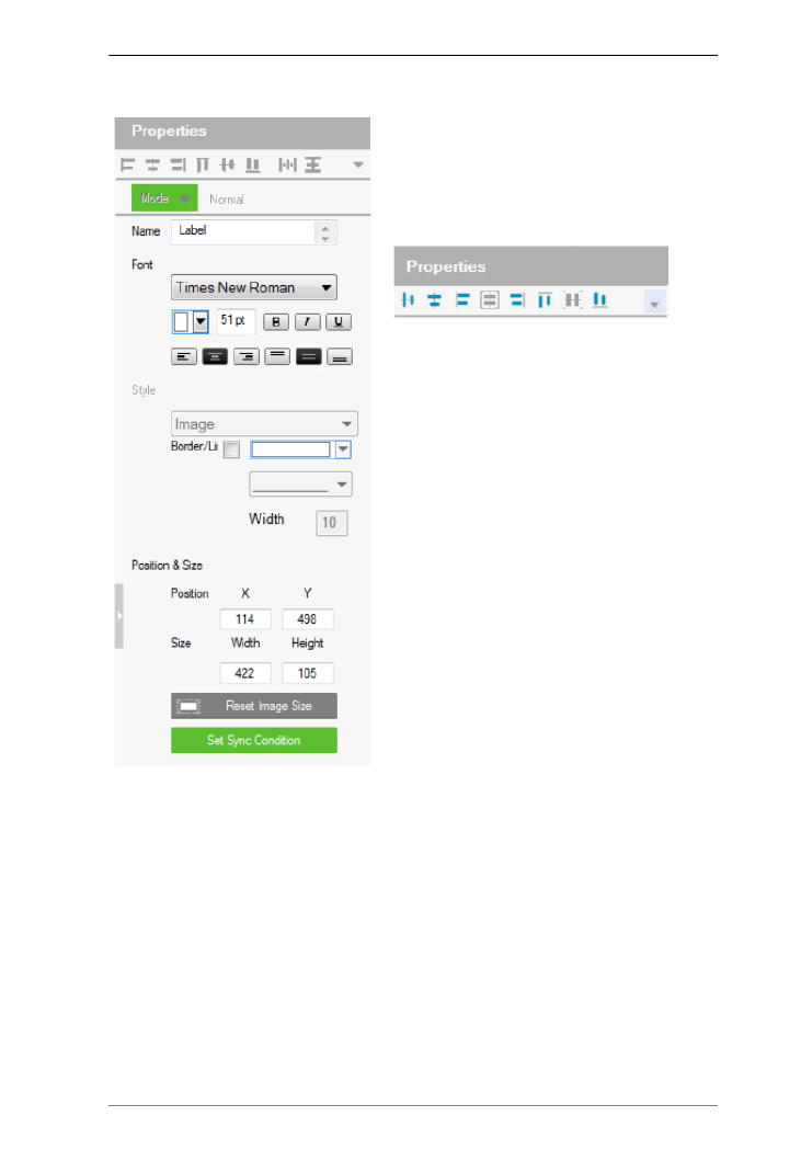
Chapter 4. ATEN Configurator (VK6000)
115
Labels
The Label properties provide settings for
the displayed text and its format.
Alignment – Aligns a group of objects.
Select multiple objects for the buttons to
become available:
Name – enter the text you want to use
for the label or slow double-click the
label on the Edit page.
Font – use the drop-down menu to
select the font type.
Color – use the drop-down menu to
change the color of the text.
Size – enter a number (1-200) to set the
size of the text.
Format– format text to Bold, Italic or
Underline.
Alignment – click a box to align the
text Right, Center or Left; and Top,
Middle or Bottom within the label box.
Border/Line – select this option to
configure the color, format, and width of
the display screen border.
Position and Size – X Y and position the label at the coordinates entered.
Width and Height set the size of the label.
Set Sync Condition – Displays the value of the selected variable in
percentage or its raw form. To create variables, see Variables, page 176.

Chapter 4. ATEN Configurator (VK6000)
117
Use the Mode drop-down menu to select the type of slider bar (Basic Slider
Bar or Advanced Slider Bar).
Basic Slider Bar
A slider bar where you enter the minimum and maximum values to
calculate the range and levels on a slider bar, and then add one command
to configure the Basic Slider Bar’s action (See Slider Value, page 133).
Choose options under Value to configure the slider bar’s range.
Direction – sets the bearing of the slider bar.
Style – click the drop-down menus to select the Foreground Color and
Background Color for the slider bar.
Value – Sets the total number of levels for the slider bar.
ASCII / HEX – click a radio button to select the format for the slider
bar values.
Minimum – enter the lowest level on the bar.
Maximum – enter the highest level on the bar.
Level – this represents the number of levels on the slider bar. You can
calculate the value of each level with the formula: Maximum Value -
Minimum Value / Level = Value Per Level. The Level is
automatically calculated according to the Minimum and Maximum
values you enter.
Position and Size – depending on whether the bar is set Vertical or
Horizontal you can use either the Size: Width or Height box to enter a
number to resize the length of the slider bar.
Set Sync Condition – Automatically synchronizes the slider bar to the
selected variable. To create a variable, see Variables, page 176.
Advanced Slider Bar
A slider bar where you set the number of levels and add a command for
each level in the bar (see Level, in the table, on page 127). Choose options
under Value to configure the slider bar’s range:
Direction – sets the bearing of the slider bar.
Style – click the drop-down menus to select the Foreground Color and
Background Color for the slider bar.
Value – Sets the total number of levels for the slider bar.Level – this
represents the number of levels on the slider bar. For each level you must
add a separate command in the Slider Bar Action – Commands list (see
Level, in the table, on page 127).
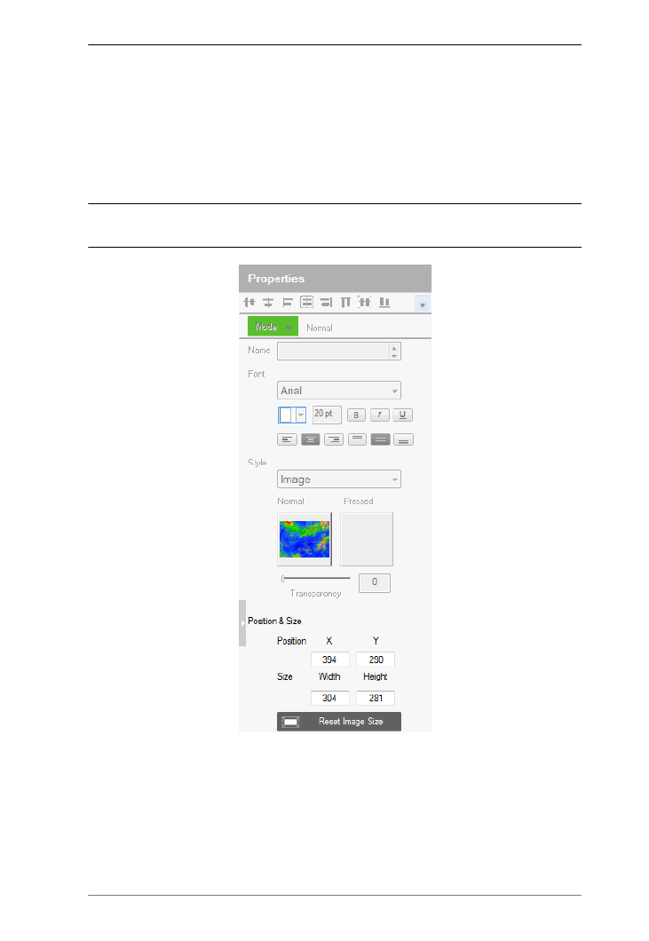
Chapter 4. ATEN Configurator (VK6000)
119
Image
The Properties for an image provide options to change and import images to
the page. Images can be layered with other objects so that they can be placed
as a background or as highlights for buttons (see Layering Images, page 120).
You can Group, Order, Align, Make Same Size or Space Evenly from the
Object menu.
Note: For imported images, make sure the file names contain English alphabets
and/or numerals only.
Style – shows the image selected. Click inside the box to import an image
(*.png,*.jpg,*.jpeg,*.bmp) to the page.
Transparency – enter a number (0-100) or use the slider-bar to set the
transparency of the image selected.
Position and Size – X Y and position the image at the coordinates entered.
Width and Height set the size of the image.
Reset Image Size – resets the image size.

ATEN Control System User Manual
120
Layering Images
Images can be layered with other objects, such as labels and buttons, so that
they can be placed as a background or as highlight for the page and/or other
objects.

Chapter 4. ATEN Configurator (VK6000)
121
Dial Kit
A dial kit template consists of a display screen and a set of dial keys. To
configure their appearance, click on the display area or a key.
Display Screen
Dial Keys
Properties for Display Screen Properties for Dial Key

ATEN Control System User Manual
122
Font – use the drop-down menu to select the font for the typed text.
Color – use the drop-down menu to change the color of the text.
Size – enter a number (1-200) to set the size of the text for the button.
Format – formats text to or Bold, Italic Underline for the button.
Alignment – click a box to align the text Right, Center or Left; and
Top, Middle or Bottom within the button box.
Style – use the drop-down menu to select the style type.
Note: The image and color settings are only applicable to dial keys.
Image – select this option to import different images for the dial key
when it is pressed and not pressed (normal).
Transparency– enter a number (0-100) or use the slider-bar to set
the transparency of the button.
Color – select this option to use different color blocks to indicate a
pressed and a normal dial key.
Border/Line – select this option to configure the color, format, and
width of the display screen border.
Position and Size – X Y and position the button at the coordinates entered.
Width and Height set the size of the button box. Click Reset Image Size to
reset the button size.
Note: If you are using the Call and End Call dials, click the dial key
to configure its action. For a detailed procedure, see Example 1: Configuring
actions of dial keys., page 134.

Chapter 4. ATEN Configurator (VK6000)
123
Frame & Line
Use frames and lines to visually group or separate control objects in your
Viewer. Click a frame or line object to configure its properties.
Style – configure the color, format, and width of the line or border of the
frame.
Rounder corder – use the scroll bar or the number box to configure the
roundness of the frame corner.
Fill – select this option to fill the frame with the selected color.
Position and Size – X Y and position the frame/line at the coordinates
entered. Width and Height set the size of the frame/line.
Frame Properties Line Properties
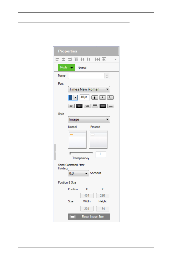
ATEN Control System User Manual
124
Object Properties for ATEN Keypad / Control Pad
After you have added a Viewer (page 102) for your Keypad / Control, you can
start configuring the Viewer. In the Viewer page, click on a button to configure
its settings. The following settings appear in the Properties panel.

ATEN Control System User Manual
126
Position and Size – X Y and position the button at the coordinates
entered. Width and Height set the size of the button box.
Set Sync Condition – Automatically synchronizes the button to the
selected variable. To create a variable, see Variables, page 176. This
option is only available for toggle buttons.
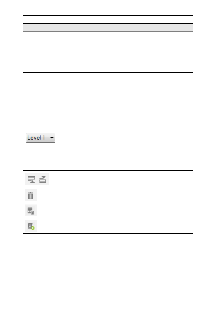
ATEN Control System User Manual
128
You can configure a button with Device commands (On, Off, Stop, Play, etc.);
as a Macro to send multiple commands to one or more devices; or as a Link
to other Viewer pages. Advanced Options allow you to add conditions to the
commands, as described on the next page.
Commands Lists the commands that initiate when the button or dial key is
pressed. Device and Advanced Option functions can be added
and associated in the Commands list together. Commands
initiate in the order that they are added to the list. Right-click in
the Commands list to use the menu selections: Move Up, Move
Down, Copy, Paste, Delete, Save as Macro, or Test Tool.
Toggle ON /
Toggle OFF
or
Press / Release
When the Button Mode (page 111) is set to Toggle or Press and
Release, the Commands list splits to set the two c commands:
Toggle ON / Press – lists the commands that initiate when the
button is first pressed or pressed and held.
Toggle OFF / Release – lists the commands that initiate when
the button is pressed a second time (Toggle), or released (Press
and Release). When the button is pressed again, Toggle ON
initiates and the cycle repeats.
The Level drop-down menu appears when an Advanced Slider
Bar is selected on the Viewer page. The number of levels in the
drop-down menu reflect the Level set in the Advanced Slider
Bar’s properties (page 117). Use the drop-down menu to select a
level and then add a command for each of the Advanced Slider
Bar’s levels (see page 133 for details).
Use Move up to move an action up in the Commands list, or
Move down to move an action down in the Commands list.
Use Delete to remove an action from the Commands list.
Use Save as Macro to save the commands in the Commands
list as a macro.
Use Test Tool to connect to a controller and test the action(s) in
the Commands list.
Setting Description

Chapter 4. ATEN Configurator (VK6000)
129
Configuring Button/Slider Bar Actions
To add one or more actions to a button, slider bar, or dial key, follow the steps
below.
1. In the project file, click to select the button, slider bar, or dial key in the
Viewer. The Button/Slider Bar Action panel appears.
2. In the Button/Slider Bar Action panel, select a Room.
3. Add commands.
For details on device functions and advanced functions, see Functions,
page 130.
a) Click a device or an advanced option to display its supported functions.
b) Double-click a function to add it to the Commands list.
c) Repeat step 3a and 3b if you wish to initiate a sequence of actions.
4. In the Commands list, double-click the commands to configure them.
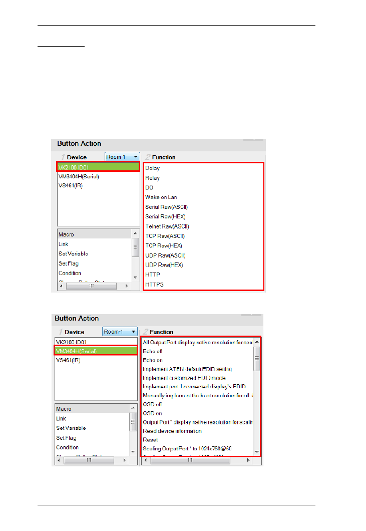
ATEN Control System User Manual
130
Functions
Button/slider bar functions can be understood as device functions and
advanced functions.
Device functions – These are functions that the selected controller or a
device managed by the controller initiates. The supported device functions
vary depending on the device you select in the Device list, as illustrated
below. For details on controller functions, see Device Functions, page 132.
Controller functions
VM3404H functions

ATEN Control System User Manual
158
Use this to set a string of characters that are set within a fixed
parameter. Enter a string of characters and use the S to set the start of
the string and E to set the end and then click Apply. The return
message will need to fit the fixed string of characters set in the text
box next to the Drop-Down Menu (see next page) for the monitor to
be triggered.
Select string with a non-fixed length
Use this to set a string of characters where the parameters are
variable. Enter a string of characters and use the S to set the start of
the string and E to set the end and then click Apply. The return
message will need to fit the fixed string of characters set in the text
box next to the Drop-Down Menu (see below) for the monitor to be
triggered.
Drop-Down Menu
Above, enter characters that the Select string with fixed length or
Select string with non-fixed length string must match and how they
must be matched: Equal to, , Not equal to Include, or Exclude for
the condition to be triggered.
Flag
Creates a flag condition for the monitor. Use the drop-down menus to set a
format (how the flag value must be matched) and the flag value for the
condition to be triggered.
I/O Input
Create a trigger signal from a device according to the voltage. Only device
with a Digital Input (dry contract) or Digital Input (VDC) port appear in
the Status list. Double-click a device in the Status list to add it to the
Product specificaties
| Merk: | ATen |
| Categorie: | Niet gecategoriseerd |
| Model: | VK248 |
Heb je hulp nodig?
Als je hulp nodig hebt met ATen VK248 stel dan hieronder een vraag en andere gebruikers zullen je antwoorden
Handleiding Niet gecategoriseerd ATen

29 Maart 2025
25 Februari 2025
25 Februari 2025
25 Februari 2025
25 Februari 2025
20 Februari 2025
17 November 2024
5 November 2024
5 November 2024
25 Juli 2024
Handleiding Niet gecategoriseerd
- Niet gecategoriseerd Electrolux
- Niet gecategoriseerd Braun
- Niet gecategoriseerd Bosch
- Niet gecategoriseerd Philips
- Niet gecategoriseerd HP
- Niet gecategoriseerd IKEA
- Niet gecategoriseerd Candy
- Niet gecategoriseerd Sony
- Niet gecategoriseerd Samsung
- Niet gecategoriseerd Delonghi
- Niet gecategoriseerd Indesit
- Niet gecategoriseerd Xiaomi
- Niet gecategoriseerd Casio
- Niet gecategoriseerd Panasonic
- Niet gecategoriseerd Nikon
- Niet gecategoriseerd Epson
- Niet gecategoriseerd Brondi
- Niet gecategoriseerd LG
- Niet gecategoriseerd Huawei
- Niet gecategoriseerd Asus
- Niet gecategoriseerd AEG
- Niet gecategoriseerd ATAG
- Niet gecategoriseerd Bauknecht
- Niet gecategoriseerd BEKO
- Niet gecategoriseerd Canon
- Niet gecategoriseerd Daewoo
- Niet gecategoriseerd DeWalt
- Niet gecategoriseerd Etna
- Niet gecategoriseerd Ford
- Niet gecategoriseerd Fysic
- Niet gecategoriseerd Garmin
- Niet gecategoriseerd Grundig
- Niet gecategoriseerd Honeywell
- Niet gecategoriseerd Inventum
- Niet gecategoriseerd JVC
- Niet gecategoriseerd JBL
- Niet gecategoriseerd Junkers
- Niet gecategoriseerd Kenwood
- Niet gecategoriseerd Krups
- Niet gecategoriseerd Karcher
- Niet gecategoriseerd Lego
- Niet gecategoriseerd Liebherr
- Niet gecategoriseerd Miele
- Niet gecategoriseerd Motorola
- Niet gecategoriseerd Medion
- Niet gecategoriseerd Nokia
- Niet gecategoriseerd Olympus
- Niet gecategoriseerd Onkyo
- Niet gecategoriseerd Pioneer
- Niet gecategoriseerd Quigg
- Niet gecategoriseerd Ravensburger
- Niet gecategoriseerd Siemens
- Niet gecategoriseerd Tefal
- Niet gecategoriseerd Toshiba
- Niet gecategoriseerd Unold
- Niet gecategoriseerd Vaillant
- Niet gecategoriseerd Volvo
- Niet gecategoriseerd VTech
- Niet gecategoriseerd Whirlpool
- Niet gecategoriseerd WOLF-Garten
- Niet gecategoriseerd Wiko
- Niet gecategoriseerd Yamaha
- Niet gecategoriseerd Yealink
- Niet gecategoriseerd Zanussi
- Niet gecategoriseerd Zibro
- Niet gecategoriseerd Hoover
- Niet gecategoriseerd A.O. Smith
- Niet gecategoriseerd A3
- Niet gecategoriseerd A4tech
- Niet gecategoriseerd ABB
- Niet gecategoriseerd ABC Design
- Niet gecategoriseerd Absima
- Niet gecategoriseerd Abus
- Niet gecategoriseerd ACCU-CHEK
- Niet gecategoriseerd Acer
- Niet gecategoriseerd ACME
- Niet gecategoriseerd Acoustic Solutions
- Niet gecategoriseerd Act
- Niet gecategoriseerd Acti
- Niet gecategoriseerd Ade
- Niet gecategoriseerd Adidas
- Niet gecategoriseerd Adler
- Niet gecategoriseerd Adobe
- Niet gecategoriseerd Aduro
- Niet gecategoriseerd Advance Acoustic
- Niet gecategoriseerd Adventuridge
- Niet gecategoriseerd AEA
- Niet gecategoriseerd Aeris
- Niet gecategoriseerd Afk
- Niet gecategoriseerd Ag Neovo
- Niet gecategoriseerd Agfa
- Niet gecategoriseerd Airlive
- Niet gecategoriseerd Airlux
- Niet gecategoriseerd Aiwa
- Niet gecategoriseerd Akai
- Niet gecategoriseerd Akasa
- Niet gecategoriseerd Akg
- Niet gecategoriseerd Al-ko
- Niet gecategoriseerd Albrecht
- Niet gecategoriseerd Alcatel
- Niet gecategoriseerd Alcon
- Niet gecategoriseerd Alecto
- Niet gecategoriseerd Alesis
- Niet gecategoriseerd Alfen
- Niet gecategoriseerd Alienware
- Niet gecategoriseerd Aligator
- Niet gecategoriseerd Allibert
- Niet gecategoriseerd Allied Telesis
- Niet gecategoriseerd Allnet
- Niet gecategoriseerd Alpen Kreuzer
- Niet gecategoriseerd Alphatronics
- Niet gecategoriseerd Alpina
- Niet gecategoriseerd Alpine
- Niet gecategoriseerd Alto
- Niet gecategoriseerd Aluratek
- Niet gecategoriseerd Amana
- Niet gecategoriseerd Amazfit
- Niet gecategoriseerd Amazon
- Niet gecategoriseerd Ambiano
- Niet gecategoriseerd Ambient
- Niet gecategoriseerd Ambrogio
- Niet gecategoriseerd American Audio
- Niet gecategoriseerd Amfra
- Niet gecategoriseerd Amica
- Niet gecategoriseerd Amiko
- Niet gecategoriseerd Ampeg
- Niet gecategoriseerd Amplicom
- Niet gecategoriseerd Amprobe
- Niet gecategoriseerd Anker
- Niet gecategoriseerd Ansmann
- Niet gecategoriseerd Antec
- Niet gecategoriseerd AOC
- Niet gecategoriseerd AOpen
- Niet gecategoriseerd Apa
- Niet gecategoriseerd Apart
- Niet gecategoriseerd Apc
- Niet gecategoriseerd Apple
- Niet gecategoriseerd Aprilia
- Niet gecategoriseerd Aqara
- Niet gecategoriseerd Aquapur
- Niet gecategoriseerd Arcelik
- Niet gecategoriseerd Archos
- Niet gecategoriseerd Arendo
- Niet gecategoriseerd Argon
- Niet gecategoriseerd Argus
- Niet gecategoriseerd Ariete
- Niet gecategoriseerd Arris
- Niet gecategoriseerd Artsound
- Niet gecategoriseerd Arturia
- Niet gecategoriseerd AS - Schwabe
- Niet gecategoriseerd Asaklitt
- Niet gecategoriseerd Ascom
- Niet gecategoriseerd Asko
- Niet gecategoriseerd Aspen
- Niet gecategoriseerd Asrock
- Niet gecategoriseerd Astralpool
- Niet gecategoriseerd Astro
- Niet gecategoriseerd Atika
- Niet gecategoriseerd Atlantic
- Niet gecategoriseerd Atlas
- Niet gecategoriseerd ATN
- Niet gecategoriseerd ATP
- Niet gecategoriseerd Audio Pro
- Niet gecategoriseerd Audio-Technica
- Niet gecategoriseerd Audiolab
- Niet gecategoriseerd Audioline
- Niet gecategoriseerd Audiovox
- Niet gecategoriseerd Audison
- Niet gecategoriseerd Aukey
- Niet gecategoriseerd Auna
- Niet gecategoriseerd Auriol
- Niet gecategoriseerd Autel
- Niet gecategoriseerd Autotek
- Niet gecategoriseerd Avanti
- Niet gecategoriseerd Avaya
- Niet gecategoriseerd AVM
- Niet gecategoriseerd AVTech
- Niet gecategoriseerd Axa
- Niet gecategoriseerd Axis
- Niet gecategoriseerd Axkid
- Niet gecategoriseerd B-tech
- Niet gecategoriseerd Baby Jogger
- Niet gecategoriseerd Baby Lock
- Niet gecategoriseerd BabyGO
- Niet gecategoriseerd BabyHome
- Niet gecategoriseerd BaByliss
- Niet gecategoriseerd Babymoov
- Niet gecategoriseerd Babyzen
- Niet gecategoriseerd Balance
- Niet gecategoriseerd Balay
- Niet gecategoriseerd Barco
- Niet gecategoriseerd Bartscher
- Niet gecategoriseerd Basetech
- Niet gecategoriseerd Batavia
- Niet gecategoriseerd Bavaria
- Niet gecategoriseerd Be Cool
- Niet gecategoriseerd Beaba
- Niet gecategoriseerd Beafon
- Niet gecategoriseerd BeamZ
- Niet gecategoriseerd Bebe Confort
- Niet gecategoriseerd Beem
- Niet gecategoriseerd Beha-Amprobe
- Niet gecategoriseerd Behringer
- Niet gecategoriseerd Belgacom
- Niet gecategoriseerd Belkin
- Niet gecategoriseerd Bellini
- Niet gecategoriseerd Benning
- Niet gecategoriseerd BenQ
- Niet gecategoriseerd Beper
- Niet gecategoriseerd Berkel
- Niet gecategoriseerd Berker
- Niet gecategoriseerd Berner
- Niet gecategoriseerd Bernina
- Niet gecategoriseerd Bertazzoni
- Niet gecategoriseerd BeSafe
- Niet gecategoriseerd Bestron
- Niet gecategoriseerd Bestway
- Niet gecategoriseerd Beurer
- Niet gecategoriseerd Beyerdynamic
- Niet gecategoriseerd BH Fitness
- Niet gecategoriseerd Bialetti
- Niet gecategoriseerd Bifinett
- Niet gecategoriseerd Bigben
- Niet gecategoriseerd Bikemate
- Niet gecategoriseerd Binatone
- Niet gecategoriseerd Bionaire
- Niet gecategoriseerd Bissell
- Niet gecategoriseerd Black Decker
- Niet gecategoriseerd Blade
- Niet gecategoriseerd Blaupunkt
- Niet gecategoriseerd Blaze
- Niet gecategoriseerd Blomberg
- Niet gecategoriseerd Blue
- Niet gecategoriseerd Bluebird
- Niet gecategoriseerd BlueBuilt
- Niet gecategoriseerd Bluesound
- Niet gecategoriseerd Blumfeldt
- Niet gecategoriseerd BMW
- Niet gecategoriseerd Bodum
- Niet gecategoriseerd Body Sculpture
- Niet gecategoriseerd Body Solid
- Niet gecategoriseerd BodyCraft
- Niet gecategoriseerd Bomann
- Niet gecategoriseerd Boneco
- Niet gecategoriseerd Bopita
- Niet gecategoriseerd Bora
- Niet gecategoriseerd Bose
- Niet gecategoriseerd Boso
- Niet gecategoriseerd Boss
- Niet gecategoriseerd Bowflex
- Niet gecategoriseerd Brabantia
- Niet gecategoriseerd Brandson
- Niet gecategoriseerd Brandt
- Niet gecategoriseerd Braun Phototechnik
- Niet gecategoriseerd Bravilor Bonamat
- Niet gecategoriseerd Brennenstuhl
- Niet gecategoriseerd Bresser
- Niet gecategoriseerd Brevi
- Niet gecategoriseerd Breville
- Niet gecategoriseerd BrightSign
- Niet gecategoriseerd Brigmton
- Niet gecategoriseerd Brinno
- Niet gecategoriseerd Brinsea
- Niet gecategoriseerd Brita
- Niet gecategoriseerd Britax
- Niet gecategoriseerd Britax-Romer
- Niet gecategoriseerd Brother
- Niet gecategoriseerd Bruder Mannesmann
- Niet gecategoriseerd Bruynzeel
- Niet gecategoriseerd Bryton
- Niet gecategoriseerd BT
- Niet gecategoriseerd Buffalo
- Niet gecategoriseerd Bugaboo
- Niet gecategoriseerd Bullet
- Niet gecategoriseerd Bunn
- Niet gecategoriseerd Burg-Wachter
- Niet gecategoriseerd Burley
- Niet gecategoriseerd Bushnell
- Niet gecategoriseerd Butler
- Niet gecategoriseerd BWT
- Niet gecategoriseerd Byron
- Niet gecategoriseerd D-Jix
- Niet gecategoriseerd D-Link
- Niet gecategoriseerd Daikin
- Niet gecategoriseerd Daitsu
- Niet gecategoriseerd Dali
- Niet gecategoriseerd Danfoss
- Niet gecategoriseerd DAP Audio
- Niet gecategoriseerd Datalogic
- Niet gecategoriseerd Davis
- Niet gecategoriseerd Definitive Technology
- Niet gecategoriseerd Defy
- Niet gecategoriseerd Dell
- Niet gecategoriseerd DeLock
- Niet gecategoriseerd Delta
- Niet gecategoriseerd Denon
- Niet gecategoriseerd Denver
- Niet gecategoriseerd Devialet
- Niet gecategoriseerd Devolo
- Niet gecategoriseerd Digi
- Niet gecategoriseerd Digitech
- Niet gecategoriseerd Digitus
- Niet gecategoriseerd Dimplex
- Niet gecategoriseerd DIO
- Niet gecategoriseerd Dirt Devil
- Niet gecategoriseerd DJI
- Niet gecategoriseerd Dnt
- Niet gecategoriseerd Dobar
- Niet gecategoriseerd DOD
- Niet gecategoriseerd Dolmar
- Niet gecategoriseerd Dometic
- Niet gecategoriseerd Domo
- Niet gecategoriseerd Domyos
- Niet gecategoriseerd Doro
- Niet gecategoriseerd Dorr
- Niet gecategoriseerd Draytek
- Niet gecategoriseerd Drayton
- Niet gecategoriseerd Dream
- Niet gecategoriseerd Dreamland
- Niet gecategoriseerd Dremel
- Niet gecategoriseerd Dual
- Niet gecategoriseerd Dualit
- Niet gecategoriseerd Dunlop
- Niet gecategoriseerd Duro
- Niet gecategoriseerd Duromax
- Niet gecategoriseerd Duronic
- Niet gecategoriseerd Duux
- Niet gecategoriseerd Dymo
- Niet gecategoriseerd Dymond
- Niet gecategoriseerd Dyson
- Niet gecategoriseerd Easy Home
- Niet gecategoriseerd Easymaxx
- Niet gecategoriseerd Easypix
- Niet gecategoriseerd Eaton
- Niet gecategoriseerd EBERLE
- Niet gecategoriseerd Eberspacher
- Niet gecategoriseerd Echo
- Niet gecategoriseerd Echowell
- Niet gecategoriseerd ECTIVE
- Niet gecategoriseerd Eden
- Niet gecategoriseerd Edesa
- Niet gecategoriseerd Edgestar
- Niet gecategoriseerd Edilkamin
- Niet gecategoriseerd Edimax
- Niet gecategoriseerd Edision
- Niet gecategoriseerd Ednet
- Niet gecategoriseerd Efbe-schott
- Niet gecategoriseerd Eheim
- Niet gecategoriseerd Einhell
- Niet gecategoriseerd Eizo
- Niet gecategoriseerd Elac
- Niet gecategoriseerd Elektrobock
- Niet gecategoriseerd Elgato
- Niet gecategoriseerd Elica
- Niet gecategoriseerd Elite
- Niet gecategoriseerd Elmo
- Niet gecategoriseerd Elro
- Niet gecategoriseerd Elta
- Niet gecategoriseerd Ematic
- Niet gecategoriseerd Emerio
- Niet gecategoriseerd Emerson
- Niet gecategoriseerd Emga
- Niet gecategoriseerd Eminent
- Niet gecategoriseerd Emmaljunga
- Niet gecategoriseerd Emporia
- Niet gecategoriseerd Emtec
- Niet gecategoriseerd Enders
- Niet gecategoriseerd Enduro
- Niet gecategoriseerd Energizer
- Niet gecategoriseerd Energy Sistem
- Niet gecategoriseerd Engel
- Niet gecategoriseerd Engenius
- Niet gecategoriseerd Entes
- Niet gecategoriseerd Envivo
- Niet gecategoriseerd Eonon
- Niet gecategoriseerd EQ-3
- Niet gecategoriseerd Ergobaby
- Niet gecategoriseerd Ernesto
- Niet gecategoriseerd Esperanza
- Niet gecategoriseerd ESX
- Niet gecategoriseerd ESYLUX
- Niet gecategoriseerd ETA
- Niet gecategoriseerd Eufab
- Niet gecategoriseerd Eufy
- Niet gecategoriseerd Eureka
- Niet gecategoriseerd Eurochron
- Niet gecategoriseerd Eurom
- Niet gecategoriseerd EverFocus
- Niet gecategoriseerd Evga
- Niet gecategoriseerd Ewent
- Niet gecategoriseerd EWT
- Niet gecategoriseerd Excalibur
- Niet gecategoriseerd Exit Toys
- Niet gecategoriseerd Expobar
- Niet gecategoriseerd Exquisit
- Niet gecategoriseerd Extech
- Niet gecategoriseerd Ezviz
- Niet gecategoriseerd Faber
- Niet gecategoriseerd FABER CASTELL
- Niet gecategoriseerd Fagor
- Niet gecategoriseerd Fakir
- Niet gecategoriseerd FALLER
- Niet gecategoriseerd Falmec
- Niet gecategoriseerd Fantec
- Niet gecategoriseerd Farberware
- Niet gecategoriseerd Faytech
- Niet gecategoriseerd Fein
- Niet gecategoriseerd Fellowes
- Niet gecategoriseerd Fender
- Niet gecategoriseerd Ferguson
- Niet gecategoriseerd Ferm
- Niet gecategoriseerd Ferroli
- Niet gecategoriseerd Festool
- Niet gecategoriseerd Fiio
- Niet gecategoriseerd Fimer
- Niet gecategoriseerd Finder
- Niet gecategoriseerd Finnlo
- Niet gecategoriseerd FireAngel
- Niet gecategoriseerd Firefriend
- Niet gecategoriseerd FireKing
- Niet gecategoriseerd First Alert
- Niet gecategoriseerd Fischer
- Niet gecategoriseerd Fisher And Paykel
- Niet gecategoriseerd Fisher Paykel
- Niet gecategoriseerd Fisher Price
- Niet gecategoriseerd Fiskars
- Niet gecategoriseerd Fissler
- Niet gecategoriseerd Fitbit
- Niet gecategoriseerd Flamingo
- Niet gecategoriseerd Flex
- Niet gecategoriseerd Flir
- Niet gecategoriseerd Florabest
- Niet gecategoriseerd Fluke
- Niet gecategoriseerd Focal
- Niet gecategoriseerd Focusrite
- Niet gecategoriseerd FoodSaver
- Niet gecategoriseerd Foppapedretti
- Niet gecategoriseerd Formuler
- Niet gecategoriseerd Foscam
- Niet gecategoriseerd Franke
- Niet gecategoriseerd Franklin
- Niet gecategoriseerd Fresh N Rebel
- Niet gecategoriseerd Friedland
- Niet gecategoriseerd Frigidaire
- Niet gecategoriseerd Frilec
- Niet gecategoriseerd Fritel
- Niet gecategoriseerd Fuji
- Niet gecategoriseerd Fujifilm
- Niet gecategoriseerd Fujitsu
- Niet gecategoriseerd Furman
- Niet gecategoriseerd Furuno
- Niet gecategoriseerd Fusion
- Niet gecategoriseerd Futaba
- Niet gecategoriseerd Fuxtec
- Niet gecategoriseerd G3 Ferrari
- Niet gecategoriseerd Gaggenau
- Niet gecategoriseerd Gaggia
- Niet gecategoriseerd Galanz
- Niet gecategoriseerd Gamma
- Niet gecategoriseerd Ganz
- Niet gecategoriseerd GAO
- Niet gecategoriseerd Garden Feelings
- Niet gecategoriseerd Garden Lights
- Niet gecategoriseerd Gardena
- Niet gecategoriseerd Gardenline
- Niet gecategoriseerd Gardol
- Niet gecategoriseerd Gastroback
- Niet gecategoriseerd Gastronoma
- Niet gecategoriseerd Gazelle
- Niet gecategoriseerd GBC
- Niet gecategoriseerd GE
- Niet gecategoriseerd Geemarc
- Niet gecategoriseerd Gembird
- Niet gecategoriseerd Gemini
- Niet gecategoriseerd Generac
- Niet gecategoriseerd Geneva
- Niet gecategoriseerd Genexis
- Niet gecategoriseerd Genius
- Niet gecategoriseerd Geomag
- Niet gecategoriseerd George Foreman
- Niet gecategoriseerd GeoVision
- Niet gecategoriseerd Germania
- Niet gecategoriseerd Geze
- Niet gecategoriseerd Giardino
- Niet gecategoriseerd Gigabyte
- Niet gecategoriseerd Giordani
- Niet gecategoriseerd Gioteck
- Niet gecategoriseerd Gira
- Niet gecategoriseerd Global
- Niet gecategoriseerd GlobalTronics
- Niet gecategoriseerd Globo
- Niet gecategoriseerd Gloria
- Niet gecategoriseerd Goclever
- Niet gecategoriseerd Godox
- Niet gecategoriseerd Goliath
- Niet gecategoriseerd Goobay
- Niet gecategoriseerd Google
- Niet gecategoriseerd GoPro
- Niet gecategoriseerd Gorenje
- Niet gecategoriseerd Gossen
- Niet gecategoriseerd Gossen Metrawatt
- Niet gecategoriseerd Gourmetmaxx
- Niet gecategoriseerd GP
- Niet gecategoriseerd GPO
- Niet gecategoriseerd GPX
- Niet gecategoriseerd Graco
- Niet gecategoriseerd Graef
- Niet gecategoriseerd Gram
- Niet gecategoriseerd Grandstream
- Niet gecategoriseerd Grasslin
- Niet gecategoriseerd GRE
- Niet gecategoriseerd Gree
- Niet gecategoriseerd Greenworks
- Niet gecategoriseerd Grixx
- Niet gecategoriseerd Grizzly
- Niet gecategoriseerd Grohe
- Niet gecategoriseerd Grothe
- Niet gecategoriseerd Ground Zero
- Niet gecategoriseerd Gude
- Niet gecategoriseerd Gutfels
- Niet gecategoriseerd Gymform
- Niet gecategoriseerd Gys
- Niet gecategoriseerd H.Koenig
- Niet gecategoriseerd Habitat
- Niet gecategoriseerd Hager
- Niet gecategoriseerd Haier
- Niet gecategoriseerd Hailo
- Niet gecategoriseerd Hama
- Niet gecategoriseerd Hammer
- Niet gecategoriseerd Hammond
- Niet gecategoriseerd Hamstra
- Niet gecategoriseerd Handicare
- Niet gecategoriseerd Hansa
- Niet gecategoriseerd Hanseatic
- Niet gecategoriseerd Hansgrohe
- Niet gecategoriseerd Hapro
- Niet gecategoriseerd Harman Kardon
- Niet gecategoriseerd Hartan
- Niet gecategoriseerd Hartke
- Niet gecategoriseerd Harvia
- Niet gecategoriseerd Hasbro
- Niet gecategoriseerd Hasselblad
- Niet gecategoriseerd Hauck
- Niet gecategoriseerd Hayward
- Niet gecategoriseerd Heidemann
- Niet gecategoriseerd Helios
- Niet gecategoriseerd Helix
- Niet gecategoriseerd Hendi
- Niet gecategoriseerd Hercules
- Niet gecategoriseerd Hertz
- Niet gecategoriseerd Hifonics
- Niet gecategoriseerd Hikoki
- Niet gecategoriseerd Hikvision
- Niet gecategoriseerd Hirschmann
- Niet gecategoriseerd Hisense
- Niet gecategoriseerd Hitachi
- Niet gecategoriseerd Hobby
- Niet gecategoriseerd Hohner
- Niet gecategoriseerd Holzmann
- Niet gecategoriseerd Home Easy
- Niet gecategoriseerd Homedics
- Niet gecategoriseerd Homelite
- Niet gecategoriseerd Honda
- Niet gecategoriseerd Honor
- Niet gecategoriseerd Horizon
- Niet gecategoriseerd Horizon Fitness
- Niet gecategoriseerd Hotpoint
- Niet gecategoriseerd Hotpoint-Ariston
- Niet gecategoriseerd Hozelock
- Niet gecategoriseerd HQ
- Niet gecategoriseerd HQ Power
- Niet gecategoriseerd HTC
- Niet gecategoriseerd Hugo Muller
- Niet gecategoriseerd Humax
- Niet gecategoriseerd Humminbird
- Niet gecategoriseerd Hunter
- Niet gecategoriseerd Husqvarna
- Niet gecategoriseerd Hyundai
- Niet gecategoriseerd I.safe Mobile
- Niet gecategoriseerd Ibico
- Niet gecategoriseerd Ibm
- Niet gecategoriseerd ICE Watch
- Niet gecategoriseerd Ices
- Niet gecategoriseerd Icom
- Niet gecategoriseerd Icon
- Niet gecategoriseerd ICU
- Niet gecategoriseerd Icy Box
- Niet gecategoriseerd ID-Tech
- Niet gecategoriseerd Ideal
- Niet gecategoriseerd Iget
- Niet gecategoriseerd Igloo
- Niet gecategoriseerd IHealth
- Niet gecategoriseerd IHome
- Niet gecategoriseerd Iiyama
- Niet gecategoriseerd ILive
- Niet gecategoriseerd Iluv
- Niet gecategoriseerd Ilve
- Niet gecategoriseerd Imperial
- Niet gecategoriseerd Infinity
- Niet gecategoriseerd InFocus
- Niet gecategoriseerd Inglesina
- Niet gecategoriseerd Innoliving
- Niet gecategoriseerd Innovaphone
- Niet gecategoriseerd Insignia
- Niet gecategoriseerd Inspire
- Niet gecategoriseerd Insta360
- Niet gecategoriseerd Intenso
- Niet gecategoriseerd Intergas
- Niet gecategoriseerd Interlogix
- Niet gecategoriseerd Intermatic
- Niet gecategoriseerd Intermec
- Niet gecategoriseerd Intex
- Niet gecategoriseerd Invacare
- Niet gecategoriseerd Inverto
- Niet gecategoriseerd Iomega
- Niet gecategoriseerd Ion
- Niet gecategoriseerd Ipevo
- Niet gecategoriseerd IQAir
- Niet gecategoriseerd IRIS
- Niet gecategoriseerd Irobot
- Niet gecategoriseerd Iseki
- Niet gecategoriseerd Itho
- Niet gecategoriseerd Itho-Daalderop
- Niet gecategoriseerd IVT
- Niet gecategoriseerd Kalorik
- Niet gecategoriseerd Kambrook
- Niet gecategoriseerd Kathrein
- Niet gecategoriseerd Kayser
- Niet gecategoriseerd KEF
- Niet gecategoriseerd Kelvinator
- Niet gecategoriseerd Kenko
- Niet gecategoriseerd Kenmore
- Niet gecategoriseerd Kensington
- Niet gecategoriseerd Kerbl
- Niet gecategoriseerd Kern
- Niet gecategoriseerd Keter
- Niet gecategoriseerd Ketron
- Niet gecategoriseerd Keurig
- Niet gecategoriseerd Kicker
- Niet gecategoriseerd Kisag
- Niet gecategoriseerd KitchenAid
- Niet gecategoriseerd Klarfit
- Niet gecategoriseerd Klarstein
- Niet gecategoriseerd KlikaanKlikuit
- Niet gecategoriseerd Klipsch
- Niet gecategoriseerd Knog
- Niet gecategoriseerd Kodak
- Niet gecategoriseerd Koenic
- Niet gecategoriseerd Koenig
- Niet gecategoriseerd Kogan
- Niet gecategoriseerd Kohler
- Niet gecategoriseerd KONFTEL
- Niet gecategoriseerd Konica Minolta
- Niet gecategoriseerd Konig
- Niet gecategoriseerd Kopp
- Niet gecategoriseerd Korg
- Niet gecategoriseerd Korona
- Niet gecategoriseerd Kress
- Niet gecategoriseerd Krontaler
- Niet gecategoriseerd Kruidvat
- Niet gecategoriseerd Kubota
- Niet gecategoriseerd Kupper
- Niet gecategoriseerd Kuppersbusch
- Niet gecategoriseerd Kyocera
- Niet gecategoriseerd LaCie
- Niet gecategoriseerd Lagrange
- Niet gecategoriseerd Laica
- Niet gecategoriseerd Lamax
- Niet gecategoriseerd Lanaform
- Niet gecategoriseerd Lancom
- Niet gecategoriseerd Landmann
- Niet gecategoriseerd Lanzar
- Niet gecategoriseerd Laser
- Niet gecategoriseerd Laserliner
- Niet gecategoriseerd Laurastar
- Niet gecategoriseerd Lava
- Niet gecategoriseerd LD Systems
- Niet gecategoriseerd Legamaster
- Niet gecategoriseerd Leica
- Niet gecategoriseerd Leifheit
- Niet gecategoriseerd Leitz
- Niet gecategoriseerd Lenco
- Niet gecategoriseerd Lenovo
- Niet gecategoriseerd Leotec
- Niet gecategoriseerd Lervia
- Niet gecategoriseerd LevelOne
- Niet gecategoriseerd Lexibook
- Niet gecategoriseerd Lexmark
- Niet gecategoriseerd Life Fitness
- Niet gecategoriseerd Lifespan
- Niet gecategoriseerd Liftmaster
- Niet gecategoriseerd LightZone
- Niet gecategoriseerd Line 6
- Niet gecategoriseerd Linksys
- Niet gecategoriseerd Little Tikes
- Niet gecategoriseerd Livarno
- Niet gecategoriseerd Livington
- Niet gecategoriseerd Livoo
- Niet gecategoriseerd Loewe
- Niet gecategoriseerd Lofrans
- Niet gecategoriseerd Logicom
- Niet gecategoriseerd Logik
- Niet gecategoriseerd Logilink
- Niet gecategoriseerd Logitech
- Niet gecategoriseerd Lorelli
- Niet gecategoriseerd Lorex
- Niet gecategoriseerd Lotus
- Niet gecategoriseerd Lowrance
- Niet gecategoriseerd Lumag
- Niet gecategoriseerd Lupilu
- Niet gecategoriseerd Luvion
- Niet gecategoriseerd Luxman
- Niet gecategoriseerd Luxor
- Niet gecategoriseerd Lynx
- Niet gecategoriseerd M-Audio
- Niet gecategoriseerd Mac Audio
- Niet gecategoriseerd Mackie
- Niet gecategoriseerd Maclaren
- Niet gecategoriseerd Macrom
- Niet gecategoriseerd Maestro
- Niet gecategoriseerd Magic Care
- Niet gecategoriseerd Magic Chef
- Niet gecategoriseerd Maginon
- Niet gecategoriseerd Magma
- Niet gecategoriseerd Magnat
- Niet gecategoriseerd Magnavox
- Niet gecategoriseerd Makita
- Niet gecategoriseerd Maktec
- Niet gecategoriseerd Mamiya
- Niet gecategoriseerd Manhattan
- Niet gecategoriseerd Manitowoc
- Niet gecategoriseerd Manta
- Niet gecategoriseerd Marantz
- Niet gecategoriseerd Marklin
- Niet gecategoriseerd Marmitek
- Niet gecategoriseerd Marquant
- Niet gecategoriseerd Marshall
- Niet gecategoriseerd Martin
- Niet gecategoriseerd Master
- Niet gecategoriseerd Master Lock
- Niet gecategoriseerd Mattel
- Niet gecategoriseerd Max
- Niet gecategoriseerd Maxcom
- Niet gecategoriseerd Maxdata
- Niet gecategoriseerd Maxell
- Niet gecategoriseerd Maxi-Cosi
- Niet gecategoriseerd Maxicool
- Niet gecategoriseerd Maximum
- Niet gecategoriseerd Maxview
- Niet gecategoriseerd Maxwell
- Niet gecategoriseerd Maxxmee
- Niet gecategoriseerd Maxxter
- Niet gecategoriseerd Maytag
- Niet gecategoriseerd MB Quart
- Niet gecategoriseerd McCulloch
- Niet gecategoriseerd Meade
- Niet gecategoriseerd Mebus
- Niet gecategoriseerd Medela
- Niet gecategoriseerd Medeli
- Niet gecategoriseerd Media-tech
- Niet gecategoriseerd Medisana
- Niet gecategoriseerd Mega
- Niet gecategoriseerd Megableu
- Niet gecategoriseerd Megasat
- Niet gecategoriseerd Megger
- Niet gecategoriseerd Meireles
- Niet gecategoriseerd Melinera
- Niet gecategoriseerd Melissa
- Niet gecategoriseerd Melitta
- Niet gecategoriseerd Meradiso
- Niet gecategoriseerd Mercury
- Niet gecategoriseerd Meridian
- Niet gecategoriseerd Merlin
- Niet gecategoriseerd Mesko
- Niet gecategoriseerd Mestic
- Niet gecategoriseerd Metabo
- Niet gecategoriseerd Metrel
- Niet gecategoriseerd Metrix
- Niet gecategoriseerd Metronic
- Niet gecategoriseerd Metz
- Niet gecategoriseerd Michelin
- Niet gecategoriseerd Microlife
- Niet gecategoriseerd Microsoft
- Niet gecategoriseerd Midea
- Niet gecategoriseerd Midland
- Niet gecategoriseerd Mikrotik
- Niet gecategoriseerd Milwaukee
- Niet gecategoriseerd Minix
- Niet gecategoriseerd Minolta
- Niet gecategoriseerd Minox
- Niet gecategoriseerd Mio
- Niet gecategoriseerd Miomare
- Niet gecategoriseerd Mistral
- Niet gecategoriseerd Mitsubishi
- Niet gecategoriseerd MJX
- Niet gecategoriseerd Mobicool
- Niet gecategoriseerd Monacor
- Niet gecategoriseerd Monitor Audio
- Niet gecategoriseerd Mophie
- Niet gecategoriseerd Morphy Richards
- Niet gecategoriseerd Moulinex
- Niet gecategoriseerd MPM
- Niet gecategoriseerd Mr Coffee
- Niet gecategoriseerd Mr Gardener
- Niet gecategoriseerd Mr Handsfree
- Niet gecategoriseerd MSI
- Niet gecategoriseerd MSpa
- Niet gecategoriseerd MTD
- Niet gecategoriseerd Mtx Audio
- Niet gecategoriseerd Mulex
- Niet gecategoriseerd Muller
- Niet gecategoriseerd Muse
- Niet gecategoriseerd Mx Onda
- Niet gecategoriseerd Nabo
- Niet gecategoriseerd Nacon
- Niet gecategoriseerd NAD
- Niet gecategoriseerd Naim
- Niet gecategoriseerd Napoleon
- Niet gecategoriseerd National Geographic
- Niet gecategoriseerd Nautilus
- Niet gecategoriseerd Navionics
- Niet gecategoriseerd Navitel
- Niet gecategoriseerd Navman
- Niet gecategoriseerd Nebula
- Niet gecategoriseerd Nec
- Niet gecategoriseerd Nedis
- Niet gecategoriseerd Neewer
- Niet gecategoriseerd Neff
- Niet gecategoriseerd Nemef
- Niet gecategoriseerd Nero
- Niet gecategoriseerd Nest
- Niet gecategoriseerd Netgear
- Niet gecategoriseerd Netis
- Niet gecategoriseerd Nevadent
- Niet gecategoriseerd New Pol
- Niet gecategoriseerd Newstar
- Niet gecategoriseerd Nextbase
- Niet gecategoriseerd Nibe
- Niet gecategoriseerd Nikkei
- Niet gecategoriseerd Nilfisk
- Niet gecategoriseerd Ninja
- Niet gecategoriseerd Nintendo
- Niet gecategoriseerd Nivona
- Niet gecategoriseerd Njoy
- Niet gecategoriseerd Nobo
- Niet gecategoriseerd Noma
- Niet gecategoriseerd NordicTrack
- Niet gecategoriseerd Nostalgia
- Niet gecategoriseerd Novation
- Niet gecategoriseerd Novis
- Niet gecategoriseerd Novy
- Niet gecategoriseerd Noxon
- Niet gecategoriseerd Nuance
- Niet gecategoriseerd Nubert
- Niet gecategoriseerd Numatic
- Niet gecategoriseerd Nuna
- Niet gecategoriseerd NutriBullet
- Niet gecategoriseerd Nvidia
- Niet gecategoriseerd Pabobo
- Niet gecategoriseerd Paladin
- Niet gecategoriseerd Palm
- Niet gecategoriseerd Palson
- Niet gecategoriseerd Paradigm
- Niet gecategoriseerd Parkside
- Niet gecategoriseerd Parrot
- Niet gecategoriseerd Pattfield
- Niet gecategoriseerd Patton
- Niet gecategoriseerd PCE
- Niet gecategoriseerd PCE Instruments
- Niet gecategoriseerd Peavey
- Niet gecategoriseerd Peerless
- Niet gecategoriseerd Peg Perego
- Niet gecategoriseerd Pelgrim
- Niet gecategoriseerd Pentax
- Niet gecategoriseerd Perel
- Niet gecategoriseerd Petsafe
- Niet gecategoriseerd Peugeot
- Niet gecategoriseerd Pfaff
- Niet gecategoriseerd Philco
- Niet gecategoriseerd Phoenix
- Niet gecategoriseerd Phoenix Gold
- Niet gecategoriseerd Phonak
- Niet gecategoriseerd Pieps
- Niet gecategoriseerd Pinolino
- Niet gecategoriseerd PKM
- Niet gecategoriseerd Plantiflor
- Niet gecategoriseerd Plantronics
- Niet gecategoriseerd Platinet
- Niet gecategoriseerd Playmobil
- Niet gecategoriseerd Playtive
- Niet gecategoriseerd Plugwise
- Niet gecategoriseerd Plustek
- Niet gecategoriseerd Pointer
- Niet gecategoriseerd Polar
- Niet gecategoriseerd POLARIS
- Niet gecategoriseerd Polaroid
- Niet gecategoriseerd Polk
- Niet gecategoriseerd Polti
- Niet gecategoriseerd Power Dynamics
- Niet gecategoriseerd Powerfix
- Niet gecategoriseerd Powerplus
- Niet gecategoriseerd Praktica
- Niet gecategoriseerd Prem-i-air
- Niet gecategoriseerd Premier
- Niet gecategoriseerd Prenatal
- Niet gecategoriseerd President
- Niet gecategoriseerd Prestigio
- Niet gecategoriseerd Primera
- Niet gecategoriseerd Primo
- Niet gecategoriseerd Princess
- Niet gecategoriseerd Privileg
- Niet gecategoriseerd Pro-User
- Niet gecategoriseerd ProfiCook
- Niet gecategoriseerd Profile
- Niet gecategoriseerd Profizelt24
- Niet gecategoriseerd Profoon
- Niet gecategoriseerd Progress
- Niet gecategoriseerd Proline
- Niet gecategoriseerd Protector
- Niet gecategoriseerd Pulsar
- Niet gecategoriseerd Pure
- Niet gecategoriseerd Pyle
- Niet gecategoriseerd Python
- Niet gecategoriseerd Q Acoustics
- Niet gecategoriseerd QNAP
- Niet gecategoriseerd Quantum
- Niet gecategoriseerd Rademacher
- Niet gecategoriseerd Radiant
- Niet gecategoriseerd Rainbow
- Niet gecategoriseerd Ranex
- Niet gecategoriseerd Rangemaster
- Niet gecategoriseerd Ravelli
- Niet gecategoriseerd Raymarine
- Niet gecategoriseerd Razer
- Niet gecategoriseerd RCA
- Niet gecategoriseerd RCF
- Niet gecategoriseerd Realme
- Niet gecategoriseerd Recaro
- Niet gecategoriseerd Redmond
- Niet gecategoriseerd Reebok
- Niet gecategoriseerd Reer
- Niet gecategoriseerd Reflecta
- Niet gecategoriseerd Reflexion
- Niet gecategoriseerd Reich
- Niet gecategoriseerd REL Acoustics
- Niet gecategoriseerd Reloop
- Niet gecategoriseerd Remington
- Niet gecategoriseerd REMKO
- Niet gecategoriseerd Renegade
- Niet gecategoriseerd Renkforce
- Niet gecategoriseerd REVITIVE
- Niet gecategoriseerd Revlon
- Niet gecategoriseerd Revo
- Niet gecategoriseerd Revox
- Niet gecategoriseerd Ricoh
- Niet gecategoriseerd Riello
- Niet gecategoriseerd Ring
- Niet gecategoriseerd Rio
- Niet gecategoriseerd Rittal
- Niet gecategoriseerd Roadstar
- Niet gecategoriseerd Robust
- Niet gecategoriseerd Roccat
- Niet gecategoriseerd Rockford Fosgate
- Niet gecategoriseerd Rocktrail
- Niet gecategoriseerd Roland
- Niet gecategoriseerd Rollei
- Niet gecategoriseerd Rommelsbacher
- Niet gecategoriseerd Rosieres
- Niet gecategoriseerd Rossmax
- Niet gecategoriseerd Rotel
- Niet gecategoriseerd Rowenta
- Niet gecategoriseerd Roxio
- Niet gecategoriseerd Royal Sovereign
- Niet gecategoriseerd RugGear
- Niet gecategoriseerd Russell Hobbs
- Niet gecategoriseerd Ryobi
- Niet gecategoriseerd Sabo
- Niet gecategoriseerd Safety 1st
- Niet gecategoriseerd Sage
- Niet gecategoriseerd Sagem
- Niet gecategoriseerd Sagemcom
- Niet gecategoriseerd Saitek
- Niet gecategoriseerd Salora
- Niet gecategoriseerd Salta
- Niet gecategoriseerd Salter
- Niet gecategoriseerd Salton
- Niet gecategoriseerd Salus
- Niet gecategoriseerd Samlex
- Niet gecategoriseerd Samson
- Niet gecategoriseerd SanDisk
- Niet gecategoriseerd Sangean
- Niet gecategoriseerd Sanitas
- Niet gecategoriseerd Santos
- Niet gecategoriseerd Sanus Systems
- Niet gecategoriseerd Sanwa
- Niet gecategoriseerd Sanyo
- Niet gecategoriseerd Saramonic
- Niet gecategoriseerd Saro
- Niet gecategoriseerd Satel
- Niet gecategoriseerd Saturn
- Niet gecategoriseerd Sauber
- Niet gecategoriseerd Scala
- Niet gecategoriseerd Scancool
- Niet gecategoriseerd Scandomestic
- Niet gecategoriseerd Schaudt
- Niet gecategoriseerd Scheppach
- Niet gecategoriseerd Schneider
- Niet gecategoriseerd Schwinn
- Niet gecategoriseerd Scott
- Niet gecategoriseerd Seagate
- Niet gecategoriseerd SeaLife
- Niet gecategoriseerd SEB
- Niet gecategoriseerd Sebo
- Niet gecategoriseerd Seecode
- Niet gecategoriseerd Segway
- Niet gecategoriseerd Seiko
- Niet gecategoriseerd Sekonic
- Niet gecategoriseerd Selfsat
- Niet gecategoriseerd Sena
- Niet gecategoriseerd Sencor
- Niet gecategoriseerd Sencys
- Niet gecategoriseerd Sennheiser
- Niet gecategoriseerd Sensiplast
- Niet gecategoriseerd Severin
- Niet gecategoriseerd Shark
- Niet gecategoriseerd Sharkoon
- Niet gecategoriseerd Sharp
- Niet gecategoriseerd Sharper Image
- Niet gecategoriseerd Shimano
- Niet gecategoriseerd Shindaiwa
- Niet gecategoriseerd Shoprider
- Niet gecategoriseerd Showtec
- Niet gecategoriseerd Siedle
- Niet gecategoriseerd Sigma
- Niet gecategoriseerd Silkn
- Niet gecategoriseerd Silva
- Niet gecategoriseerd Silvercrest
- Niet gecategoriseerd Silverline
- Niet gecategoriseerd Simeo
- Niet gecategoriseerd Simpark
- Niet gecategoriseerd Simrad
- Niet gecategoriseerd Singer
- Niet gecategoriseerd Sirius
- Niet gecategoriseerd Sitecom
- Niet gecategoriseerd Skil
- Niet gecategoriseerd Skullcandy
- Niet gecategoriseerd Skymaster
- Niet gecategoriseerd SMA
- Niet gecategoriseerd Smart
- Niet gecategoriseerd Smartwares
- Niet gecategoriseerd SMC
- Niet gecategoriseerd Smeg
- Niet gecategoriseerd Snom
- Niet gecategoriseerd Sodastream
- Niet gecategoriseerd Soehnle
- Niet gecategoriseerd Sogo
- Niet gecategoriseerd Solac
- Niet gecategoriseerd Sole Fitness
- Niet gecategoriseerd Solis
- Niet gecategoriseerd Solo
- Niet gecategoriseerd Somfy
- Niet gecategoriseerd Sommer
- Niet gecategoriseerd Sonos
- Niet gecategoriseerd Sonuus
- Niet gecategoriseerd Soundcraft
- Niet gecategoriseerd Soundmaster
- Niet gecategoriseerd Soundstream
- Niet gecategoriseerd Spektrum
- Niet gecategoriseerd SPT
- Niet gecategoriseerd Spypoint
- Niet gecategoriseerd Stabo
- Niet gecategoriseerd Stadler Form
- Niet gecategoriseerd Stamina
- Niet gecategoriseerd Standard Horizon
- Niet gecategoriseerd Stanley
- Niet gecategoriseerd Starlyf
- Niet gecategoriseerd Steba
- Niet gecategoriseerd Steelseries
- Niet gecategoriseerd Steinberg
- Niet gecategoriseerd Steinel
- Niet gecategoriseerd Stiebel Eltron
- Niet gecategoriseerd Stiga
- Niet gecategoriseerd Stihl
- Niet gecategoriseerd Stinger
- Niet gecategoriseerd Stirling
- Niet gecategoriseerd Stokke
- Niet gecategoriseerd Strong
- Niet gecategoriseerd Subaru
- Niet gecategoriseerd Suevia
- Niet gecategoriseerd Sunbeam
- Niet gecategoriseerd Sunny
- Niet gecategoriseerd Sunpentown
- Niet gecategoriseerd Sunstech
- Niet gecategoriseerd Suntec
- Niet gecategoriseerd Superrollo
- Niet gecategoriseerd SuperTooth
- Niet gecategoriseerd Suunto
- Niet gecategoriseerd Suzuki
- Niet gecategoriseerd Swan
- Niet gecategoriseerd Sweex
- Niet gecategoriseerd Swissvoice
- Niet gecategoriseerd Switel
- Niet gecategoriseerd SXT
- Niet gecategoriseerd Sylvania
- Niet gecategoriseerd Syma
- Niet gecategoriseerd Synology
- Niet gecategoriseerd TacTic
- Niet gecategoriseerd Tamiya
- Niet gecategoriseerd Tamron
- Niet gecategoriseerd Tanaka
- Niet gecategoriseerd Tanita
- Niet gecategoriseerd Tannoy
- Niet gecategoriseerd Targus
- Niet gecategoriseerd Tascam
- Niet gecategoriseerd Taurus
- Niet gecategoriseerd Taylor
- Niet gecategoriseerd TC Helicon
- Niet gecategoriseerd TCL
- Niet gecategoriseerd Teac
- Niet gecategoriseerd Team
- Niet gecategoriseerd Technaxx
- Niet gecategoriseerd Technicolor
- Niet gecategoriseerd Technics
- Niet gecategoriseerd Technika
- Niet gecategoriseerd Technisat
- Niet gecategoriseerd Techno Line
- Niet gecategoriseerd Technoline
- Niet gecategoriseerd Teka
- Niet gecategoriseerd Telefunken
- Niet gecategoriseerd Telestar
- Niet gecategoriseerd TELEX
- Niet gecategoriseerd Telstra
- Niet gecategoriseerd Teltonika
- Niet gecategoriseerd Tenda
- Niet gecategoriseerd Tepro
- Niet gecategoriseerd Termozeta
- Niet gecategoriseerd Terraillon
- Niet gecategoriseerd Terratec
- Niet gecategoriseerd Tesla
- Niet gecategoriseerd Teufel
- Niet gecategoriseerd Tevion
- Niet gecategoriseerd Texas
- Niet gecategoriseerd Texas Instruments
- Niet gecategoriseerd TFA
- Niet gecategoriseerd Theben
- Niet gecategoriseerd Thermador
- Niet gecategoriseerd Thermor
- Niet gecategoriseerd Thetford
- Niet gecategoriseerd Thinkware
- Niet gecategoriseerd Thomas
- Niet gecategoriseerd Thomson
- Niet gecategoriseerd Thorens
- Niet gecategoriseerd Thrustmaster
- Niet gecategoriseerd Thule
- Niet gecategoriseerd Tiger
- Niet gecategoriseerd Tiptel
- Niet gecategoriseerd Toa
- Niet gecategoriseerd Tommee Tippee
- Niet gecategoriseerd TomTom
- Niet gecategoriseerd Toolcraft
- Niet gecategoriseerd Toolland
- Niet gecategoriseerd Toorx
- Niet gecategoriseerd Topcraft
- Niet gecategoriseerd Tork
- Niet gecategoriseerd Tormatic
- Niet gecategoriseerd Toro
- Niet gecategoriseerd Tower
- Niet gecategoriseerd Toyotomi
- Niet gecategoriseerd TP Link
- Niet gecategoriseerd Transcend
- Niet gecategoriseerd TranzX
- Niet gecategoriseerd Trebs
- Niet gecategoriseerd Trekstor
- Niet gecategoriseerd Trendnet
- Niet gecategoriseerd Triax
- Niet gecategoriseerd Trigano
- Niet gecategoriseerd Tristar
- Niet gecategoriseerd Triton
- Niet gecategoriseerd Trixie
- Niet gecategoriseerd Tronic
- Niet gecategoriseerd Trotec
- Niet gecategoriseerd Troy-Bilt
- Niet gecategoriseerd Truelife
- Niet gecategoriseerd Truma
- Niet gecategoriseerd Trust
- Niet gecategoriseerd Tunturi
- Niet gecategoriseerd Turmix
- Niet gecategoriseerd Tusa
- Niet gecategoriseerd Twisper
- Niet gecategoriseerd Ufesa
- Niet gecategoriseerd Ultimate
- Niet gecategoriseerd Ultimate Speed
- Niet gecategoriseerd Uni-T
- Niet gecategoriseerd Uniden
- Niet gecategoriseerd Unify
- Niet gecategoriseerd United Office
- Niet gecategoriseerd Universal Remote Control
- Niet gecategoriseerd UPM
- Niet gecategoriseerd Upo
- Niet gecategoriseerd V-Tac
- Niet gecategoriseerd V-Zug
- Niet gecategoriseerd Valeo
- Niet gecategoriseerd Varta
- Niet gecategoriseerd VAX
- Niet gecategoriseerd VCM
- Niet gecategoriseerd Veho
- Niet gecategoriseerd Velbus
- Niet gecategoriseerd Velleman
- Niet gecategoriseerd Velux
- Niet gecategoriseerd Venta
- Niet gecategoriseerd Ventura
- Niet gecategoriseerd Ventus
- Niet gecategoriseerd Verbatim
- Niet gecategoriseerd Veritas
- Niet gecategoriseerd Verizon
- Niet gecategoriseerd Vermeiren
- Niet gecategoriseerd Vestel
- Niet gecategoriseerd Vestfrost
- Niet gecategoriseerd Viatek
- Niet gecategoriseerd Vicks
- Niet gecategoriseerd Victor
- Niet gecategoriseerd Viessmann
- Niet gecategoriseerd View Quest
- Niet gecategoriseerd Viewsonic
- Niet gecategoriseerd Viking
- Niet gecategoriseerd Vileda
- Niet gecategoriseerd Vinci
- Niet gecategoriseerd Viper
- Niet gecategoriseerd VirtuFit
- Niet gecategoriseerd Vitalmaxx
- Niet gecategoriseerd Vitamix
- Niet gecategoriseerd Vitek
- Niet gecategoriseerd Vivanco
- Niet gecategoriseerd Vivax
- Niet gecategoriseerd Vivitar
- Niet gecategoriseerd Vivo
- Niet gecategoriseerd Vivotek
- Niet gecategoriseerd Vizio
- Niet gecategoriseerd Vogels
- Niet gecategoriseerd Vogue
- Niet gecategoriseerd Voigtlander
- Niet gecategoriseerd Volkswagen
- Niet gecategoriseerd Voltcraft
- Niet gecategoriseerd Vonroc
- Niet gecategoriseerd Vonyx
- Niet gecategoriseerd Vornado
- Niet gecategoriseerd Vortex
- Niet gecategoriseerd Wachendorff
- Niet gecategoriseerd Wacom
- Niet gecategoriseerd Waeco
- Niet gecategoriseerd Wagner
- Niet gecategoriseerd Wallas
- Niet gecategoriseerd Wamsler
- Niet gecategoriseerd Wasco
- Niet gecategoriseerd Waterpik
- Niet gecategoriseerd Watson
- Niet gecategoriseerd Waves
- Niet gecategoriseerd Weasy
- Niet gecategoriseerd Weber
- Niet gecategoriseerd WEG
- Niet gecategoriseerd Wehkamp
- Niet gecategoriseerd Weishaupt
- Niet gecategoriseerd Weller
- Niet gecategoriseerd Welltech
- Niet gecategoriseerd Western Digital
- Niet gecategoriseerd Westfalia
- Niet gecategoriseerd Westinghouse
- Niet gecategoriseerd WHALE
- Niet gecategoriseerd Wharfedale
- Niet gecategoriseerd Wiha
- Niet gecategoriseerd WilTec
- Niet gecategoriseerd Winegard
- Niet gecategoriseerd Winix
- Niet gecategoriseerd Withings
- Niet gecategoriseerd Wmf
- Niet gecategoriseerd Wolf
- Niet gecategoriseerd Woods
- Niet gecategoriseerd Woood
- Niet gecategoriseerd Workzone
- Niet gecategoriseerd Worx
- Niet gecategoriseerd Wurth
- Niet gecategoriseerd X4 Life
- Niet gecategoriseerd X4-Tech
- Niet gecategoriseerd Xavax
- Niet gecategoriseerd XGIMI
- Niet gecategoriseerd Xlyne
- Niet gecategoriseerd Xoro
- Niet gecategoriseerd Xterra
- Niet gecategoriseerd Xtorm
- Niet gecategoriseerd Xunzel
- Niet gecategoriseerd Yaesu
- Niet gecategoriseerd Yale
- Niet gecategoriseerd Ygnis
- Niet gecategoriseerd Yongnuo
- Niet gecategoriseerd Yphix
- Niet gecategoriseerd Yukon
- Niet gecategoriseerd Zagg
- Niet gecategoriseerd Zalman
- Niet gecategoriseerd Zebra
- Niet gecategoriseerd Zehnder
- Niet gecategoriseerd Zelmer
- Niet gecategoriseerd Zenec
- Niet gecategoriseerd Zennio
- Niet gecategoriseerd Zepter
- Niet gecategoriseerd Ziggo
- Niet gecategoriseerd Zipper
- Niet gecategoriseerd Zodiac
- Niet gecategoriseerd Zoofari
- Niet gecategoriseerd Zoom
- Niet gecategoriseerd ZTE
- Niet gecategoriseerd ZyXEL
- Niet gecategoriseerd Jabra
- Niet gecategoriseerd Jamo
- Niet gecategoriseerd Jane
- Niet gecategoriseerd Jata
- Niet gecategoriseerd Jay-tech
- Niet gecategoriseerd Jensen
- Niet gecategoriseerd Jilong
- Niet gecategoriseerd JL Audio
- Niet gecategoriseerd JML
- Niet gecategoriseerd Jocca
- Niet gecategoriseerd Jocel
- Niet gecategoriseerd Joie
- Niet gecategoriseerd Joovy
- Niet gecategoriseerd Jotul
- Niet gecategoriseerd Joy-it
- Niet gecategoriseerd Juki
- Niet gecategoriseerd Jumbo
- Niet gecategoriseerd Jung
- Niet gecategoriseerd Jura
- Niet gecategoriseerd Juwel
- Niet gecategoriseerd Jysk
- Niet gecategoriseerd Oase
- Niet gecategoriseerd Oceanic
- Niet gecategoriseerd Oertli
- Niet gecategoriseerd OJ ELECTRONICS
- Niet gecategoriseerd OK
- Niet gecategoriseerd OKAY
- Niet gecategoriseerd Olimpia Splendid
- Niet gecategoriseerd Olivetti
- Niet gecategoriseerd Olympia
- Niet gecategoriseerd Omega
- Niet gecategoriseerd Omnitronic
- Niet gecategoriseerd Omron
- Niet gecategoriseerd One For All
- Niet gecategoriseerd OneConcept
- Niet gecategoriseerd OnePlus
- Niet gecategoriseerd OneTouch
- Niet gecategoriseerd Oppo
- Niet gecategoriseerd Optex
- Niet gecategoriseerd Optoma
- Niet gecategoriseerd Orange
- Niet gecategoriseerd Orbis
- Niet gecategoriseerd Orbit
- Niet gecategoriseerd Oregon Scientific
- Niet gecategoriseerd Orion
- Niet gecategoriseerd Osann
- Niet gecategoriseerd Osram
- Niet gecategoriseerd Oster
- Niet gecategoriseerd Otolift
- Niet gecategoriseerd Outdoorchef
- Niet gecategoriseerd Overmax
- Niet gecategoriseerd Ozito
- Niet gecategoriseerd SunPower
- Niet gecategoriseerd 3M
- Niet gecategoriseerd Anthem
- Niet gecategoriseerd Christopeit
- Niet gecategoriseerd Clas Ohlson
- Niet gecategoriseerd Concept2
- Niet gecategoriseerd Crivit
- Niet gecategoriseerd Cambridge
- Niet gecategoriseerd McIntosh
- Niet gecategoriseerd Vincent
- Niet gecategoriseerd Canicom
- Niet gecategoriseerd Valore
- Niet gecategoriseerd Trimble
- Niet gecategoriseerd Becken
- Niet gecategoriseerd Black And Decker
- Niet gecategoriseerd Camry
- Niet gecategoriseerd Caso
- Niet gecategoriseerd Clatronic
- Niet gecategoriseerd Concept
- Niet gecategoriseerd Continental Edison
- Niet gecategoriseerd Crofton
- Niet gecategoriseerd Cuisinart
- Niet gecategoriseerd ECG
- Niet gecategoriseerd Elba
- Niet gecategoriseerd First Austria
- Niet gecategoriseerd Guzzanti
- Niet gecategoriseerd Hamilton Beach
- Niet gecategoriseerd Heinner
- Niet gecategoriseerd Imetec
- Niet gecategoriseerd Izzy
- Niet gecategoriseerd Khind
- Niet gecategoriseerd Mellerware
- Niet gecategoriseerd OBH Nordica
- Niet gecategoriseerd Optimum
- Niet gecategoriseerd Orbegozo
- Niet gecategoriseerd Pitsos
- Niet gecategoriseerd Profilo
- Niet gecategoriseerd Scarlett
- Niet gecategoriseerd Sinbo
- Niet gecategoriseerd Trisa
- Niet gecategoriseerd Vox
- Niet gecategoriseerd Wilfa
- Niet gecategoriseerd Alpatronix
- Niet gecategoriseerd Audeze
- Niet gecategoriseerd B-Speech
- Niet gecategoriseerd Bang And Olufsen
- Niet gecategoriseerd Bowers And Wilkins
- Niet gecategoriseerd Caliber
- Niet gecategoriseerd Champion
- Niet gecategoriseerd Connect IT
- Niet gecategoriseerd Creative
- Niet gecategoriseerd CSL
- Niet gecategoriseerd Exibel
- Niet gecategoriseerd GoGEN
- Niet gecategoriseerd JLab
- Niet gecategoriseerd Krüger And Matz
- Niet gecategoriseerd Macally
- Niet gecategoriseerd Monoprice
- Niet gecategoriseerd Naxa
- Niet gecategoriseerd NGS
- Niet gecategoriseerd Niceboy
- Niet gecategoriseerd POGS
- Niet gecategoriseerd Proscan
- Niet gecategoriseerd Schwaiger
- Niet gecategoriseerd Shure
- Niet gecategoriseerd Steren
- Niet gecategoriseerd T'nB
- Niet gecategoriseerd Umidigi
- Niet gecategoriseerd Anslut
- Niet gecategoriseerd Barska
- Niet gecategoriseerd Carmen
- Niet gecategoriseerd Kayoba
- Niet gecategoriseerd Klein Tools
- Niet gecategoriseerd Lupine
- Niet gecategoriseerd Maglite
- Niet gecategoriseerd Nitecore
- Niet gecategoriseerd Olight
- Niet gecategoriseerd Pelican
- Niet gecategoriseerd Petzl
- Niet gecategoriseerd Princeton Tec
- Niet gecategoriseerd Urrea
- Niet gecategoriseerd Walther
- Niet gecategoriseerd Wetelux
- Niet gecategoriseerd Aicon
- Niet gecategoriseerd Cocraft
- Niet gecategoriseerd Draper
- Niet gecategoriseerd Meec Tools
- Niet gecategoriseerd Rapid
- Niet gecategoriseerd Senco
- Niet gecategoriseerd Best Fitness
- Niet gecategoriseerd Steelbody
- Niet gecategoriseerd True
- Niet gecategoriseerd Baninni
- Niet gecategoriseerd Lionelo
- Niet gecategoriseerd Kunft
- Niet gecategoriseerd Prince
- Niet gecategoriseerd Yamato
- Niet gecategoriseerd Playtive Junior
- Niet gecategoriseerd Zenit
- Niet gecategoriseerd R-Vent
- Niet gecategoriseerd Soler And Palau
- Niet gecategoriseerd Genesis
- Niet gecategoriseerd Leen Bakker
- Niet gecategoriseerd Parisot
- Niet gecategoriseerd Pericles
- Niet gecategoriseerd Tvilum
- Niet gecategoriseerd Svedbergs
- Niet gecategoriseerd Vantec
- Niet gecategoriseerd Crock-Pot
- Niet gecategoriseerd Instant
- Niet gecategoriseerd Nutrichef
- Niet gecategoriseerd Hilti
- Niet gecategoriseerd Autodesk
- Niet gecategoriseerd Bentley
- Niet gecategoriseerd Corel
- Niet gecategoriseerd DoorBird
- Niet gecategoriseerd Parallels
- Niet gecategoriseerd Safescan
- Niet gecategoriseerd Sophos
- Niet gecategoriseerd Ubiquiti Networks
- Niet gecategoriseerd Ferplast
- Niet gecategoriseerd Fluval
- Niet gecategoriseerd Sicce
- Niet gecategoriseerd SuperFish
- Niet gecategoriseerd Tetra
- Niet gecategoriseerd Hamron
- Niet gecategoriseerd Kraftwerk
- Niet gecategoriseerd Clarion
- Niet gecategoriseerd Sissel
- Niet gecategoriseerd Cobra
- Niet gecategoriseerd Deutz
- Niet gecategoriseerd Perkins
- Niet gecategoriseerd Arthur Martin
- Niet gecategoriseerd Aspes
- Niet gecategoriseerd AYA
- Niet gecategoriseerd Bella
- Niet gecategoriseerd Blanco
- Niet gecategoriseerd Bush
- Niet gecategoriseerd Campomatic
- Niet gecategoriseerd Caple
- Niet gecategoriseerd CDA
- Niet gecategoriseerd Comfee
- Niet gecategoriseerd Constructa
- Niet gecategoriseerd Corberó
- Niet gecategoriseerd Crosley
- Niet gecategoriseerd Cylinda
- Niet gecategoriseerd Dacor
- Niet gecategoriseerd Danby
- Niet gecategoriseerd Elektron
- Niet gecategoriseerd Equator
- Niet gecategoriseerd Esatto
- Niet gecategoriseerd Euromaid
- Niet gecategoriseerd Flavel
- Niet gecategoriseerd GAM
- Niet gecategoriseerd EMOS
- Niet gecategoriseerd Hobart
- Niet gecategoriseerd Infiniton
- Niet gecategoriseerd Jenn-Air
- Niet gecategoriseerd Televés
- Niet gecategoriseerd Kaiser
- Niet gecategoriseerd Kernau
- Niet gecategoriseerd King
- Niet gecategoriseerd KKT Kolbe
- Niet gecategoriseerd Conceptronic
- Niet gecategoriseerd Monogram
- Niet gecategoriseerd Nevir
- Niet gecategoriseerd Orima
- Niet gecategoriseerd Sauter
- Niet gecategoriseerd Simpson
- Niet gecategoriseerd Summit
- Niet gecategoriseerd Svan
- Niet gecategoriseerd Thor
- Niet gecategoriseerd Aerotec
- Niet gecategoriseerd Cotech
- Niet gecategoriseerd Power Craft
- Niet gecategoriseerd Tacklife
- Niet gecategoriseerd Truper
- Niet gecategoriseerd DPA
- Niet gecategoriseerd IMG Stageline
- Niet gecategoriseerd MXL
- Niet gecategoriseerd Festo
- Niet gecategoriseerd Fieldmann
- Niet gecategoriseerd Mafell
- Niet gecategoriseerd Tracer
- Niet gecategoriseerd Bright Starts
- Niet gecategoriseerd Chicco
- Niet gecategoriseerd Celestron
- Niet gecategoriseerd Levenhuk
- Niet gecategoriseerd Cabasse
- Niet gecategoriseerd Aplic
- Niet gecategoriseerd Metapace
- Niet gecategoriseerd McGregor
- Niet gecategoriseerd Stannah
- Niet gecategoriseerd Blackburn
- Niet gecategoriseerd Lezyne
- Niet gecategoriseerd Topeak
- Niet gecategoriseerd Babybjörn
- Niet gecategoriseerd BabyDan
- Niet gecategoriseerd Century
- Niet gecategoriseerd Cosatto
- Niet gecategoriseerd Geuther
- Niet gecategoriseerd Ingenuity
- Niet gecategoriseerd Mamas & Papas
- Niet gecategoriseerd Paidi
- Niet gecategoriseerd Silver Cross
- Niet gecategoriseerd Vipack
- Niet gecategoriseerd KidKraft
- Niet gecategoriseerd MADE
- Niet gecategoriseerd Nolte
- Niet gecategoriseerd Samac
- Niet gecategoriseerd Wacker Neuson
- Niet gecategoriseerd Active Era
- Niet gecategoriseerd Ardes
- Niet gecategoriseerd Conair
- Niet gecategoriseerd Cresta
- Niet gecategoriseerd Eldom
- Niet gecategoriseerd Grunkel
- Niet gecategoriseerd Lümme
- Niet gecategoriseerd Miniland
- Niet gecategoriseerd Teesa
- Niet gecategoriseerd Heaven Fresh
- Niet gecategoriseerd Heylo
- Niet gecategoriseerd Oreck
- Niet gecategoriseerd Prime3
- Niet gecategoriseerd Proficare
- Niet gecategoriseerd Coline
- Niet gecategoriseerd Haeger
- Niet gecategoriseerd Proctor Silex
- Niet gecategoriseerd Waring Commercial
- Niet gecategoriseerd Black Diamond
- Niet gecategoriseerd Coleman
- Niet gecategoriseerd Easy Camp
- Niet gecategoriseerd Kelty
- Niet gecategoriseerd Outwell
- Niet gecategoriseerd Raclet
- Niet gecategoriseerd Rusta
- Niet gecategoriseerd Vango
- Niet gecategoriseerd Vaude
- Niet gecategoriseerd Newline
- Niet gecategoriseerd Brondell
- Niet gecategoriseerd Duravit
- Niet gecategoriseerd Pressalit
- Niet gecategoriseerd Schütte
- Niet gecategoriseerd Arlo
- Niet gecategoriseerd Atlona
- Niet gecategoriseerd Avidsen
- Niet gecategoriseerd Hamlet
- Niet gecategoriseerd Hive
- Niet gecategoriseerd SereneLife
- Niet gecategoriseerd Davita
- Niet gecategoriseerd Cooler Master
- Niet gecategoriseerd NZXT
- Niet gecategoriseerd SilverStone
- Niet gecategoriseerd Thermaltake
- Niet gecategoriseerd Yeyian
- Niet gecategoriseerd Brentwood
- Niet gecategoriseerd Albert Heijn
- Niet gecategoriseerd Proxxon
- Niet gecategoriseerd Marvel
- Niet gecategoriseerd Artusi
- Niet gecategoriseerd Cadac
- Niet gecategoriseerd Campart
- Niet gecategoriseerd Char-Broil
- Niet gecategoriseerd Gasmate
- Niet gecategoriseerd Rösle
- Niet gecategoriseerd Kessler
- Niet gecategoriseerd Medel
- Niet gecategoriseerd DCG
- Niet gecategoriseerd Kubo
- Niet gecategoriseerd Pyrex
- Niet gecategoriseerd Vakoss
- Niet gecategoriseerd Witt
- Niet gecategoriseerd AdHoc
- Niet gecategoriseerd Aarke
- Niet gecategoriseerd Tescoma
- Niet gecategoriseerd Arkon
- Niet gecategoriseerd Biltema
- Niet gecategoriseerd Defender
- Niet gecategoriseerd Rocketfish
- Niet gecategoriseerd Topmove
- Niet gecategoriseerd AIC
- Niet gecategoriseerd Alba
- Niet gecategoriseerd Elbe
- Niet gecategoriseerd Majestic
- Niet gecategoriseerd Prologue
- Niet gecategoriseerd Trevi
- Niet gecategoriseerd Malmbergs
- Niet gecategoriseerd Porter-Cable
- Niet gecategoriseerd Sun Joe
- Niet gecategoriseerd Yard Force
- Niet gecategoriseerd Challenge
- Niet gecategoriseerd Cramer
- Niet gecategoriseerd EGO
- Niet gecategoriseerd Gtech
- Niet gecategoriseerd Hurricane
- Niet gecategoriseerd Maruyama
- Niet gecategoriseerd Spear & Jackson
- Niet gecategoriseerd BBB
- Niet gecategoriseerd Busch And Müller
- Niet gecategoriseerd Cateye
- Niet gecategoriseerd Goodram
- Niet gecategoriseerd Spanninga
- Niet gecategoriseerd Crunch
- Niet gecategoriseerd ETON
- Niet gecategoriseerd Trasman
- Niet gecategoriseerd Cilio
- Niet gecategoriseerd Royal Catering
- Niet gecategoriseerd Calor
- Niet gecategoriseerd Gima
- Niet gecategoriseerd LandRoller
- Niet gecategoriseerd Little Giant
- Niet gecategoriseerd Adesso
- Niet gecategoriseerd Rapoo
- Niet gecategoriseerd Vivolink
- Niet gecategoriseerd ADATA
- Niet gecategoriseerd Crucial
- Niet gecategoriseerd Intel
- Niet gecategoriseerd QOMO
- Niet gecategoriseerd Eurolite
- Niet gecategoriseerd BDI
- Niet gecategoriseerd Corsair
- Niet gecategoriseerd Cougar
- Niet gecategoriseerd Interstuhl
- Niet gecategoriseerd Primus
- Niet gecategoriseerd Techly
- Niet gecategoriseerd TOGU
- Niet gecategoriseerd Zuiver
- Niet gecategoriseerd Leatherman
- Niet gecategoriseerd OutNowTech
- Niet gecategoriseerd Contax
- Niet gecategoriseerd GFM
- Niet gecategoriseerd Phase One
- Niet gecategoriseerd Flexispot
- Niet gecategoriseerd Cello
- Niet gecategoriseerd Brydge
- Niet gecategoriseerd Cherry
- Niet gecategoriseerd Deltaco
- Niet gecategoriseerd KeepOut
- Niet gecategoriseerd Natec
- Niet gecategoriseerd Ozone
- Niet gecategoriseerd Penclic
- Niet gecategoriseerd Satechi
- Niet gecategoriseerd Savio
- Niet gecategoriseerd SIIG
- Niet gecategoriseerd Sven
- Niet gecategoriseerd Broan
- Niet gecategoriseerd Dedra
- Niet gecategoriseerd Graphite
- Niet gecategoriseerd Patriot
- Niet gecategoriseerd RIDGID
- Niet gecategoriseerd Tryton
- Niet gecategoriseerd DSC
- Niet gecategoriseerd GA.MA
- Niet gecategoriseerd Max Pro
- Niet gecategoriseerd Revamp
- Niet gecategoriseerd Visage
- Niet gecategoriseerd Piet Boon
- Niet gecategoriseerd Comelit
- Niet gecategoriseerd M-e
- Niet gecategoriseerd NuTone
- Niet gecategoriseerd REV
- Niet gecategoriseerd CMI
- Niet gecategoriseerd Hecht
- Niet gecategoriseerd Herkules
- Niet gecategoriseerd Könner & Söhnen
- Niet gecategoriseerd Avantree
- Niet gecategoriseerd CasaFan
- Niet gecategoriseerd KDK
- Niet gecategoriseerd Kichler
- Niet gecategoriseerd AXI
- Niet gecategoriseerd Quadro
- Niet gecategoriseerd Smoby
- Niet gecategoriseerd Lenoxx
- Niet gecategoriseerd Blow
- Niet gecategoriseerd Scosche
- Niet gecategoriseerd Sensei
- Niet gecategoriseerd Weil
- Niet gecategoriseerd Estella
- Niet gecategoriseerd Riviera And Bar
- Niet gecategoriseerd NUK
- Niet gecategoriseerd Oricom
- Niet gecategoriseerd Fisher
- Niet gecategoriseerd 4moms
- Niet gecategoriseerd Anex
- Niet gecategoriseerd BRIO
- Niet gecategoriseerd Cybex
- Niet gecategoriseerd Evenflo
- Niet gecategoriseerd Phil And Teds
- Niet gecategoriseerd Genie
- Niet gecategoriseerd ClearOne
- Niet gecategoriseerd Hudora
- Niet gecategoriseerd Forza
- Niet gecategoriseerd Evoc
- Niet gecategoriseerd Osprey
- Niet gecategoriseerd Salewa
- Niet gecategoriseerd Bimar
- Niet gecategoriseerd Crane
- Niet gecategoriseerd Goodway
- Niet gecategoriseerd Lasko
- Niet gecategoriseerd The Grainfather
- Niet gecategoriseerd Cata
- Niet gecategoriseerd U-Line
- Niet gecategoriseerd Zephyr
- Niet gecategoriseerd 4smarts
- Niet gecategoriseerd Duracell
- Niet gecategoriseerd C3
- Niet gecategoriseerd MiPow
- Niet gecategoriseerd Cosori
- Niet gecategoriseerd Tripp Lite
- Niet gecategoriseerd Veripart
- Niet gecategoriseerd Baby Brezza
- Niet gecategoriseerd Creda
- Niet gecategoriseerd James
- Niet gecategoriseerd Chacon
- Niet gecategoriseerd MSW
- Niet gecategoriseerd Ordex
- Niet gecategoriseerd Safco
- Niet gecategoriseerd Carpigiani
- Niet gecategoriseerd Hard Head
- Niet gecategoriseerd Unilux
- Niet gecategoriseerd Naish
- Niet gecategoriseerd Woonexpress
- Niet gecategoriseerd Caberg
- Niet gecategoriseerd Lazer
- Niet gecategoriseerd Schuberth
- Niet gecategoriseerd Dr. Browns
- Niet gecategoriseerd TRIUS
- Niet gecategoriseerd Lantus
- Niet gecategoriseerd Novo Nordisk
- Niet gecategoriseerd Sanofi
- Niet gecategoriseerd American DJ
- Niet gecategoriseerd Antari
- Niet gecategoriseerd Chauvet
- Niet gecategoriseerd Exagerate
- Niet gecategoriseerd Mr. Heater
- Niet gecategoriseerd SHX
- Niet gecategoriseerd Tesy
- Niet gecategoriseerd Foster
- Niet gecategoriseerd ACE
- Niet gecategoriseerd Nexa
- Niet gecategoriseerd Swann
- Niet gecategoriseerd Woox
- Niet gecategoriseerd Musical Fidelity
- Niet gecategoriseerd Nûby
- Niet gecategoriseerd Baby Trend
- Niet gecategoriseerd Lindam
- Niet gecategoriseerd Valcom
- Niet gecategoriseerd Capital Sports
- Niet gecategoriseerd Carnielli
- Niet gecategoriseerd Integra
- Niet gecategoriseerd Peloton
- Niet gecategoriseerd Craftsman
- Niet gecategoriseerd Rikon
- Niet gecategoriseerd Vroomshoop
- Niet gecategoriseerd Honey-Can-Do
- Niet gecategoriseerd Kwantum
- Niet gecategoriseerd Camec
- Niet gecategoriseerd Godrej
- Niet gecategoriseerd Tiny Love
- Niet gecategoriseerd Milectric
- Niet gecategoriseerd Morris
- Niet gecategoriseerd Orava
- Niet gecategoriseerd Rommer
- Niet gecategoriseerd Signature
- Niet gecategoriseerd Simplicity
- Niet gecategoriseerd Dash
- Niet gecategoriseerd ASSA ABLOY
- Niet gecategoriseerd Dorma
- Niet gecategoriseerd Dormakaba
- Niet gecategoriseerd Eurospec
- Niet gecategoriseerd Nilox
- Niet gecategoriseerd CaterChef
- Niet gecategoriseerd Approx
- Niet gecategoriseerd Billow
- Niet gecategoriseerd SPC
- Niet gecategoriseerd Sungale
- Niet gecategoriseerd Cecotec
- Niet gecategoriseerd Baxi
- Niet gecategoriseerd Beretta
- Niet gecategoriseerd Milan
- Niet gecategoriseerd Q-CONNECT
- Niet gecategoriseerd Best
- Niet gecategoriseerd Nodor
- Niet gecategoriseerd Thermex
- Niet gecategoriseerd Canyon
- Niet gecategoriseerd Cisco
- Niet gecategoriseerd Foreo
- Niet gecategoriseerd Oromed
- Niet gecategoriseerd SureFlap
- Niet gecategoriseerd Schumacher
- Niet gecategoriseerd ARRI
- Niet gecategoriseerd Verto
- Niet gecategoriseerd Sanus
- Niet gecategoriseerd Hamax
- Niet gecategoriseerd Alphacool
- Niet gecategoriseerd AZZA
- Niet gecategoriseerd Enermax
- Niet gecategoriseerd Noctua
- Niet gecategoriseerd SainSmart
- Niet gecategoriseerd Seville Classics
- Niet gecategoriseerd Bauhn
- Niet gecategoriseerd Block
- Niet gecategoriseerd Pro-Ject
- Niet gecategoriseerd Rega
- Niet gecategoriseerd Moldex
- Niet gecategoriseerd Ledger
- Niet gecategoriseerd Contour
- Niet gecategoriseerd Cowon
- Niet gecategoriseerd EVOLVEO
- Niet gecategoriseerd Prixton
- Niet gecategoriseerd Whistler
- Niet gecategoriseerd JOBY
- Niet gecategoriseerd Vello
- Niet gecategoriseerd Snow Joe
- Niet gecategoriseerd Cruz
- Niet gecategoriseerd G3
- Niet gecategoriseerd Flama
- Niet gecategoriseerd Weston
- Niet gecategoriseerd Victron Energy
- Niet gecategoriseerd Carrier
- Niet gecategoriseerd Delta Dore
- Niet gecategoriseerd Fantini Cosmi
- Niet gecategoriseerd Vemer
- Niet gecategoriseerd Warmup
- Niet gecategoriseerd Nesco
- Niet gecategoriseerd RGV
- Niet gecategoriseerd Vision
- Niet gecategoriseerd LC-Power
- Niet gecategoriseerd ZOTAC
- Niet gecategoriseerd Matrox
- Niet gecategoriseerd MBM
- Niet gecategoriseerd True & Tidy
- Niet gecategoriseerd Vanish
- Niet gecategoriseerd Goldtouch
- Niet gecategoriseerd HyperX
- Niet gecategoriseerd Compex
- Niet gecategoriseerd Atomos
- Niet gecategoriseerd Natuzzi
- Niet gecategoriseerd Polisport
- Niet gecategoriseerd AMC
- Niet gecategoriseerd Citronic
- Niet gecategoriseerd Crown
- Niet gecategoriseerd Dynacord
- Niet gecategoriseerd Phonic
- Niet gecategoriseerd Yorkville
- Niet gecategoriseerd De Buyer
- Niet gecategoriseerd Catit
- Niet gecategoriseerd Lund
- Niet gecategoriseerd Apelson
- Niet gecategoriseerd Benavent
- Niet gecategoriseerd Eico
- Niet gecategoriseerd Furrion
- Niet gecategoriseerd Coby
- Niet gecategoriseerd Rinnai
- Niet gecategoriseerd MedFolio
- Niet gecategoriseerd Asustor
- Niet gecategoriseerd Infasecure
- Niet gecategoriseerd Sparco
- Niet gecategoriseerd Gefen
- Niet gecategoriseerd Deltronic
- Niet gecategoriseerd Ei Electronics
- Niet gecategoriseerd Fibaro
- Niet gecategoriseerd Fito
- Niet gecategoriseerd GEV
- Niet gecategoriseerd Kidde
- Niet gecategoriseerd Crosscall
- Niet gecategoriseerd Maze
- Niet gecategoriseerd Minn Kota
- Niet gecategoriseerd Plum
- Niet gecategoriseerd DMax
- Niet gecategoriseerd Jupiter
- Niet gecategoriseerd Peach
- Niet gecategoriseerd Rexel
- Niet gecategoriseerd CradlePoint
- Niet gecategoriseerd Juniper
- Niet gecategoriseerd Planet
- Niet gecategoriseerd Innr
- Niet gecategoriseerd Lucide
- Niet gecategoriseerd Massive
- Niet gecategoriseerd Maul
- Niet gecategoriseerd Paulmann
- Niet gecategoriseerd Bixolon
- Niet gecategoriseerd Brady
- Niet gecategoriseerd Datacard
- Niet gecategoriseerd GoDEX
- Niet gecategoriseerd WEN
- Niet gecategoriseerd Genelec
- Niet gecategoriseerd Cardiostrong
- Niet gecategoriseerd Barkan
- Niet gecategoriseerd Bretford
- Niet gecategoriseerd Chief
- Niet gecategoriseerd Doffler
- Niet gecategoriseerd Gabor
- Niet gecategoriseerd Marker
- Niet gecategoriseerd Debel
- Niet gecategoriseerd AcuRite
- Niet gecategoriseerd Etekcity
- Niet gecategoriseerd Dahle
- Niet gecategoriseerd Audix
- Niet gecategoriseerd Califone
- Niet gecategoriseerd Swingline
- Niet gecategoriseerd Chamberlain
- Niet gecategoriseerd Munchkin
- Niet gecategoriseerd Lescha
- Niet gecategoriseerd Tornado
- Niet gecategoriseerd Imperia
- Niet gecategoriseerd Steiner
- Niet gecategoriseerd Zeiss
- Niet gecategoriseerd Buzz Rack
- Niet gecategoriseerd Masterbuilt
- Niet gecategoriseerd Testo
- Niet gecategoriseerd WAGAN
- Niet gecategoriseerd Viridian
- Niet gecategoriseerd Respironics
- Niet gecategoriseerd Cressi
- Niet gecategoriseerd Burigotto
- Niet gecategoriseerd System Sensor
- Niet gecategoriseerd Exit
- Niet gecategoriseerd Springfree
- Niet gecategoriseerd Intellinet
- Niet gecategoriseerd Avocor
- Niet gecategoriseerd Eastron
- Niet gecategoriseerd Energenie
- Niet gecategoriseerd Cubot
- Niet gecategoriseerd NUX
- Niet gecategoriseerd Thomann
- Niet gecategoriseerd Karma
- Niet gecategoriseerd HeartSine
- Niet gecategoriseerd Sunding
- Niet gecategoriseerd DoubleSight
- Niet gecategoriseerd Accucold
- Niet gecategoriseerd Acros
- Niet gecategoriseerd Husky
- Niet gecategoriseerd Lec
- Niet gecategoriseerd BabyOno
- Niet gecategoriseerd Lansinoh
- Niet gecategoriseerd Neno
- Niet gecategoriseerd Carson
- Niet gecategoriseerd FIMI
- Niet gecategoriseerd Monster
- Niet gecategoriseerd Artrom
- Niet gecategoriseerd ISi
- Niet gecategoriseerd Bron-Coucke
- Niet gecategoriseerd Dreambaby
- Niet gecategoriseerd Swift
- Niet gecategoriseerd Ansco
- Niet gecategoriseerd Cosina
- Niet gecategoriseerd Graflex
- Niet gecategoriseerd Ilford
- Niet gecategoriseerd Petri
- Niet gecategoriseerd Cleanmaxx
- Niet gecategoriseerd BCA
- Niet gecategoriseerd Mammut
- Niet gecategoriseerd FIAP
- Niet gecategoriseerd Pontec
- Niet gecategoriseerd Xblitz
- Niet gecategoriseerd West Elm
- Niet gecategoriseerd Hoshizaki
- Niet gecategoriseerd Clearblue
- Niet gecategoriseerd CyberPower
- Niet gecategoriseerd Coolaroo
- Niet gecategoriseerd Razor
- Niet gecategoriseerd Babylonia
- Niet gecategoriseerd Infantino
- Niet gecategoriseerd Kolcraft
- Niet gecategoriseerd Manduca
- Niet gecategoriseerd Havis
- Niet gecategoriseerd I-Tec
- Niet gecategoriseerd SEIKI
- Niet gecategoriseerd SunBriteTV
- Niet gecategoriseerd Magnus
- Niet gecategoriseerd Manfrotto
- Niet gecategoriseerd Sachtler
- Niet gecategoriseerd Sevenoak
- Niet gecategoriseerd Zhiyun
- Niet gecategoriseerd Beautifly
- Niet gecategoriseerd Holman
- Niet gecategoriseerd Stabila
- Niet gecategoriseerd Testboy
- Niet gecategoriseerd Alpha Tools
- Niet gecategoriseerd Hazet
- Niet gecategoriseerd 3B
- Niet gecategoriseerd ResMed
- Niet gecategoriseerd Supermicro
- Niet gecategoriseerd Bobrick
- Niet gecategoriseerd Newport Brass
- Niet gecategoriseerd Purell
- Niet gecategoriseerd Harley Benton
- Niet gecategoriseerd Clage
- Niet gecategoriseerd Damixa
- Niet gecategoriseerd Elkay
- Niet gecategoriseerd Gustavsberg
- Niet gecategoriseerd Oras
- Niet gecategoriseerd Sloan
- Niet gecategoriseerd TOTO
- Niet gecategoriseerd Sime
- Niet gecategoriseerd G-Technology
- Niet gecategoriseerd Platinum
- Niet gecategoriseerd CGV
- Niet gecategoriseerd Heitech
- Niet gecategoriseerd LTC
- Niet gecategoriseerd Full Boar
- Niet gecategoriseerd Yato
- Niet gecategoriseerd Cabstone
- Niet gecategoriseerd Cardo
- Niet gecategoriseerd Dreamgear
- Niet gecategoriseerd Interphone
- Niet gecategoriseerd Jonsered
- Niet gecategoriseerd Qualcast
- Niet gecategoriseerd Total
- Niet gecategoriseerd Singercon
- Niet gecategoriseerd Dynamic
- Niet gecategoriseerd Karibu
- Niet gecategoriseerd Reber
- Niet gecategoriseerd SKROSS
- Niet gecategoriseerd Aida
- Niet gecategoriseerd Ninebot
- Niet gecategoriseerd Cottons
- Niet gecategoriseerd Bestgreen
- Niet gecategoriseerd Gianni Ferrari
- Niet gecategoriseerd Hayter
- Niet gecategoriseerd Masport
- Niet gecategoriseerd Morrison
- Niet gecategoriseerd Livall
- Niet gecategoriseerd Proteca
- Niet gecategoriseerd Tripp
- Niet gecategoriseerd Ankarsrum
- Niet gecategoriseerd Galcon
- Niet gecategoriseerd Nelson
- Niet gecategoriseerd Barazza
- Niet gecategoriseerd Winia
- Niet gecategoriseerd Bravilor
- Niet gecategoriseerd ZAZU
- Niet gecategoriseerd Growatt
- Niet gecategoriseerd Lenmar
- Niet gecategoriseerd Exo-Terra
- Niet gecategoriseerd Lexar
- Niet gecategoriseerd Lindy
- Niet gecategoriseerd Nordea
- Niet gecategoriseerd Xcellon
- Niet gecategoriseerd Euro Cuisine
- Niet gecategoriseerd OSO
- Niet gecategoriseerd AVerMedia
- Niet gecategoriseerd Lumens
- Niet gecategoriseerd Jabsco
- Niet gecategoriseerd TensCare
- Niet gecategoriseerd Ovente
- Niet gecategoriseerd Ursus Trotter
- Niet gecategoriseerd Nanni
- Niet gecategoriseerd Herlag
- Niet gecategoriseerd Roba
- Niet gecategoriseerd MOZA
- Niet gecategoriseerd IOGEAR
- Niet gecategoriseerd Séura
- Niet gecategoriseerd Basbau
- Niet gecategoriseerd ELO
- Niet gecategoriseerd SVAT
- Niet gecategoriseerd Stalco
- Niet gecategoriseerd Petmate
- Niet gecategoriseerd Black Box
- Niet gecategoriseerd Auto Joe
- Niet gecategoriseerd Fortinet
- Niet gecategoriseerd Youin
- Niet gecategoriseerd Croozer
- Niet gecategoriseerd IFM
- Niet gecategoriseerd Perfecta
- Niet gecategoriseerd Cricut
- Niet gecategoriseerd Hähnel
- Niet gecategoriseerd DataVideo
- Niet gecategoriseerd Be Quiet!
- Niet gecategoriseerd Kindermann
- Niet gecategoriseerd Berg
- Niet gecategoriseerd Simplified MFG
- Niet gecategoriseerd GLP
- Niet gecategoriseerd Hombli
- Niet gecategoriseerd Powertec
- Niet gecategoriseerd ART
- Niet gecategoriseerd Valeton
- Niet gecategoriseerd Tiptop Audio
- Niet gecategoriseerd Summit Audio
- Niet gecategoriseerd SKS
- Niet gecategoriseerd Musway
- Niet gecategoriseerd Wago
- Niet gecategoriseerd Smith & Wesson
- Niet gecategoriseerd Avalon
- Niet gecategoriseerd Plant Craft
- Niet gecategoriseerd Dubatti
- Niet gecategoriseerd Baumr-AG
- Niet gecategoriseerd GW Instek
- Niet gecategoriseerd Totolink
- Niet gecategoriseerd Vaddio
- Niet gecategoriseerd La Crosse Technology
- Niet gecategoriseerd HK Audio
- Niet gecategoriseerd Bogen
- Niet gecategoriseerd Da-Lite
- Niet gecategoriseerd CaterCool
- Niet gecategoriseerd Allen & Heath
- Niet gecategoriseerd Ariston Thermo
- Niet gecategoriseerd Kyoritsu
- Niet gecategoriseerd Air King
- Niet gecategoriseerd SBS
- Niet gecategoriseerd KiddyGuard
- Niet gecategoriseerd AJA
- Niet gecategoriseerd Galaxy Audio
- Niet gecategoriseerd Adj
- Niet gecategoriseerd Ikan
- Niet gecategoriseerd Dahua Technology
- Niet gecategoriseerd AV:link
- Niet gecategoriseerd Neumann
- Niet gecategoriseerd Native Instruments
- Niet gecategoriseerd Walkstool
- Niet gecategoriseerd Apogee
- Niet gecategoriseerd Peerless-AV
- Niet gecategoriseerd Pyle Pro
- Niet gecategoriseerd PreSonus
- Niet gecategoriseerd NOCO
- Niet gecategoriseerd Inkbird
- Niet gecategoriseerd Electro-Voice
- Niet gecategoriseerd Mercusys
- Niet gecategoriseerd Playseat
- Niet gecategoriseerd Weihrauch Sport
- Niet gecategoriseerd Martha Stewart
- Niet gecategoriseerd Reolink
- Niet gecategoriseerd Glem Gas
- Niet gecategoriseerd IK Multimedia
- Niet gecategoriseerd Elation
- Niet gecategoriseerd IDance
- Niet gecategoriseerd Rupert Neve Designs
- Niet gecategoriseerd Carel
- Niet gecategoriseerd BOHLT
- Niet gecategoriseerd Simplecom
- Niet gecategoriseerd Speed-Link
- Niet gecategoriseerd Endress
- Niet gecategoriseerd Millenium
- Niet gecategoriseerd Owon
- Niet gecategoriseerd Aqua Joe
- Niet gecategoriseerd Valueline
- Niet gecategoriseerd Chandler
- Niet gecategoriseerd RDL
- Niet gecategoriseerd Austrian Audio
- Niet gecategoriseerd Busch-Jaeger
- Niet gecategoriseerd Cellular Line
- Niet gecategoriseerd EVE
- Niet gecategoriseerd Countryman
- Niet gecategoriseerd Chord
- Niet gecategoriseerd Fredenstein
- Niet gecategoriseerd Aruba
- Niet gecategoriseerd Swissonic
- Niet gecategoriseerd Sound Machines
- Niet gecategoriseerd Aviom
- Niet gecategoriseerd QSC
- Niet gecategoriseerd Happy Plugs
- Niet gecategoriseerd BABY Born
- Niet gecategoriseerd Levoit
- Niet gecategoriseerd Traxxas
- Niet gecategoriseerd Audac
- Niet gecategoriseerd Eltako
- Niet gecategoriseerd Azden
- Niet gecategoriseerd Aerial
- Niet gecategoriseerd ESI
- Niet gecategoriseerd Grillmeister
- Niet gecategoriseerd For_Q
- Niet gecategoriseerd GVM
- Niet gecategoriseerd Coyote
- Niet gecategoriseerd Rain Bird
- Niet gecategoriseerd Irritrol
- Niet gecategoriseerd Kasda
- Niet gecategoriseerd Marshall Electronics
- Niet gecategoriseerd Shuttle
- Niet gecategoriseerd Puky
- Niet gecategoriseerd GFI System
- Niet gecategoriseerd Ctek
- Niet gecategoriseerd Swarovski Optik
- Niet gecategoriseerd Vacmaster
- Niet gecategoriseerd Golden Age Project
- Niet gecategoriseerd Spin Master
- Niet gecategoriseerd Huion
- Niet gecategoriseerd TC Electronic
- Niet gecategoriseerd BOYA
- Niet gecategoriseerd Rode
- Niet gecategoriseerd 4ms
- Niet gecategoriseerd Anchor Audio
- Niet gecategoriseerd Dantherm
- Niet gecategoriseerd Projecta
- Niet gecategoriseerd Lyman
- Niet gecategoriseerd Genaray
- Niet gecategoriseerd Cablexpert
- Niet gecategoriseerd Stelton
- Niet gecategoriseerd DAS Audio
- Niet gecategoriseerd Eventide
- Niet gecategoriseerd Radial Engineering
- Niet gecategoriseerd Blackmagic Design
- Niet gecategoriseerd Noveen
- Niet gecategoriseerd Cre8audio
- Niet gecategoriseerd Nanlite
- Niet gecategoriseerd BakkerElkhuizen
- Niet gecategoriseerd Boyo
- Niet gecategoriseerd IKRA
- Niet gecategoriseerd IOttie
- Niet gecategoriseerd Profoto
- Niet gecategoriseerd XPG
- Niet gecategoriseerd Namco Bandai Games
- Niet gecategoriseerd Trio Lighting
- Niet gecategoriseerd Valco Baby
- Niet gecategoriseerd Argoclima
- Niet gecategoriseerd Metra
- Niet gecategoriseerd Hestan
- Niet gecategoriseerd Cadel
- Niet gecategoriseerd ThinkFun
- Niet gecategoriseerd Miggo
- Niet gecategoriseerd Russound
- Niet gecategoriseerd ISDT
- Niet gecategoriseerd Abac
- Niet gecategoriseerd Slik
- Niet gecategoriseerd Celly
- Niet gecategoriseerd Skan Holz
- Niet gecategoriseerd Comica
- Niet gecategoriseerd CRUX
- Niet gecategoriseerd ZLine
- Niet gecategoriseerd Audient
- Niet gecategoriseerd Heller
- Niet gecategoriseerd Hegel
- Niet gecategoriseerd RGBlink
- Niet gecategoriseerd EMSA
- Niet gecategoriseerd Waldbeck
- Niet gecategoriseerd CTA Digital
- Niet gecategoriseerd Bazooka
- Niet gecategoriseerd PAX
- Niet gecategoriseerd K&K Sound
- Niet gecategoriseerd Dutchbone
- Niet gecategoriseerd MyPhone
- Niet gecategoriseerd Fanvil
- Niet gecategoriseerd Noise Engineering
- Niet gecategoriseerd PAC
- Niet gecategoriseerd Wentronic
- Niet gecategoriseerd Xtreme
- Niet gecategoriseerd RAVPower
- Niet gecategoriseerd Mooer
- Niet gecategoriseerd Hooker
- Niet gecategoriseerd Dynaudio
- Niet gecategoriseerd August
- Niet gecategoriseerd Adder
- Niet gecategoriseerd Gitzo
- Niet gecategoriseerd DBX
- Niet gecategoriseerd ECS
- Niet gecategoriseerd Selec
- Niet gecategoriseerd Aiphone
- Niet gecategoriseerd Tivoli Audio
- Niet gecategoriseerd Senal
- Niet gecategoriseerd JETI
- Niet gecategoriseerd EQ3
- Niet gecategoriseerd Karlik
- Niet gecategoriseerd Comark
- Niet gecategoriseerd Homematic IP
- Niet gecategoriseerd N8WERK
- Niet gecategoriseerd Calex
- Niet gecategoriseerd Clean Air Optima
- Niet gecategoriseerd Tovsto
- Niet gecategoriseerd Learning Resources
- Niet gecategoriseerd Xaoc
- Niet gecategoriseerd Qute
- Niet gecategoriseerd Victrola
- Niet gecategoriseerd Lanberg
- Niet gecategoriseerd Kopul
- Niet gecategoriseerd AENO
- Niet gecategoriseerd Proaim
- Niet gecategoriseerd Nexxt
- Niet gecategoriseerd Glock
- Niet gecategoriseerd Linn
- Niet gecategoriseerd Martin Logan
- Niet gecategoriseerd Vorago
- Niet gecategoriseerd Anton/Bauer
- Niet gecategoriseerd Extron
- Niet gecategoriseerd Ibiza Sound
- Niet gecategoriseerd Promethean
- Niet gecategoriseerd HyperIce
- Niet gecategoriseerd Basil
- Niet gecategoriseerd Chipolino
- Niet gecategoriseerd Nxg
- Niet gecategoriseerd AGM
- Niet gecategoriseerd Ambient Recording
- Niet gecategoriseerd Diana
- Niet gecategoriseerd Tandberg Data
- Niet gecategoriseerd Fostex
- Niet gecategoriseerd Prowise
- Niet gecategoriseerd Impact
- Niet gecategoriseerd Areca
- Niet gecategoriseerd Mousetrapper
- Niet gecategoriseerd TSC
- Niet gecategoriseerd Sikkens
- Niet gecategoriseerd DEXP
- Niet gecategoriseerd Burris
- Niet gecategoriseerd GolfBuddy
- Niet gecategoriseerd Proel
- Niet gecategoriseerd FBT
- Niet gecategoriseerd NodOn
- Niet gecategoriseerd Edge
- Niet gecategoriseerd Endorphin.es
- Niet gecategoriseerd MIPRO
- Niet gecategoriseerd Bracketron
- Niet gecategoriseerd Solid State Logic
- Niet gecategoriseerd XYZprinting
- Niet gecategoriseerd Computherm
- Niet gecategoriseerd MTM
- Niet gecategoriseerd X-Sense
- Niet gecategoriseerd IMC Toys
- Niet gecategoriseerd Neets
- Niet gecategoriseerd NAV-TV
- Niet gecategoriseerd Wooden Camera
- Niet gecategoriseerd AMX
- Niet gecategoriseerd SEH
- Niet gecategoriseerd AudioQuest
- Niet gecategoriseerd Powerblade
- Niet gecategoriseerd HiFi ROSE
- Niet gecategoriseerd OSD Audio
- Niet gecategoriseerd WMD
- Niet gecategoriseerd Andover
- Niet gecategoriseerd Moog
- Niet gecategoriseerd Arctic Cooling
- Niet gecategoriseerd Blackstar
- Niet gecategoriseerd Ergotron
- Niet gecategoriseerd Equip
- Niet gecategoriseerd Stairville
- Niet gecategoriseerd Crestron
- Niet gecategoriseerd RME
- Niet gecategoriseerd Black Lion Audio
- Niet gecategoriseerd Crayola
- Niet gecategoriseerd Avid
- Niet gecategoriseerd CTOUCH
- Niet gecategoriseerd Adastra
- Niet gecategoriseerd Konig & Meyer
- Niet gecategoriseerd Meister Craft
- Niet gecategoriseerd Yeastar
- Niet gecategoriseerd Laserworld
- Niet gecategoriseerd Chuango
- Niet gecategoriseerd Hori
- Niet gecategoriseerd Klavis
- Niet gecategoriseerd ORNO
- Niet gecategoriseerd ETiger
- Niet gecategoriseerd Bison
- Niet gecategoriseerd Foxconn
- Niet gecategoriseerd EMG
- Niet gecategoriseerd Icy Dock
- Niet gecategoriseerd Make Noise
- Niet gecategoriseerd TeachLogic
- Niet gecategoriseerd Maytronics
- Niet gecategoriseerd Charge Amps
- Niet gecategoriseerd Newland
- Niet gecategoriseerd Aeon Labs
- Niet gecategoriseerd Shokz
- Niet gecategoriseerd TEF
- Niet gecategoriseerd Dreame
- Niet gecategoriseerd Life Gear
- Niet gecategoriseerd SMART Technologies
- Niet gecategoriseerd ZYCOO
- Niet gecategoriseerd Kontakt Chemie
- Niet gecategoriseerd Riccar
- Niet gecategoriseerd Clean Paper
- Niet gecategoriseerd OpenVox
- Niet gecategoriseerd Electro Harmonix
- Niet gecategoriseerd Erica Synths
- Niet gecategoriseerd SkyRC
- Niet gecategoriseerd Atdec
- Niet gecategoriseerd Portech
- Niet gecategoriseerd Markbass
- Niet gecategoriseerd Kugoo
- Niet gecategoriseerd StarTech.com
- Niet gecategoriseerd Style Me Up
- Niet gecategoriseerd Flexson
- Niet gecategoriseerd Rossi
- Niet gecategoriseerd Nimble
- Niet gecategoriseerd Eissound
- Niet gecategoriseerd Everdure
- Niet gecategoriseerd TCM FX
- Niet gecategoriseerd Snakebyte
- Niet gecategoriseerd IBasso
- Niet gecategoriseerd Warm Audio
- Niet gecategoriseerd AudioControl
- Niet gecategoriseerd Purpleline
- Niet gecategoriseerd Nerf
- Niet gecategoriseerd Nature's Truth
- Niet gecategoriseerd Emeril Lagasse
- Niet gecategoriseerd 2hp
- Niet gecategoriseerd Kelkay
- Niet gecategoriseerd Baby Annabell
- Niet gecategoriseerd Crane Song
- Niet gecategoriseerd PureLink
- Niet gecategoriseerd HyperJuice
- Niet gecategoriseerd Ruger
- Niet gecategoriseerd Sonnet
- Niet gecategoriseerd UX
- Niet gecategoriseerd Gamdias
- Niet gecategoriseerd SPL
- Niet gecategoriseerd Multimetrix
- Niet gecategoriseerd Solid
- Niet gecategoriseerd Hubelino
- Niet gecategoriseerd Aputure
- Niet gecategoriseerd Gerni
- Niet gecategoriseerd Jupio
- Niet gecategoriseerd Infomir
- Niet gecategoriseerd Blaser
- Niet gecategoriseerd Heatit
- Niet gecategoriseerd Deaf Bonce
- Niet gecategoriseerd ProForm
- Niet gecategoriseerd UTEPO
- Niet gecategoriseerd Lindell Audio
- Niet gecategoriseerd Think Tank
- Niet gecategoriseerd Timbersled
- Niet gecategoriseerd After Later Audio
- Niet gecategoriseerd Twelve South
- Niet gecategoriseerd Koala
- Niet gecategoriseerd Drawmer
- Niet gecategoriseerd Blue Sky
- Niet gecategoriseerd ColorKey
- Niet gecategoriseerd Thronmax
- Niet gecategoriseerd PowerXL
- Niet gecategoriseerd IXS
- Niet gecategoriseerd Etymotic
- Niet gecategoriseerd AirTurn
- Niet gecategoriseerd Turbo Air
- Niet gecategoriseerd Zega
- Niet gecategoriseerd Morningstar
- Niet gecategoriseerd CreativeWorKs
- Niet gecategoriseerd Beghelli
- Niet gecategoriseerd Advantech
- Niet gecategoriseerd Moxa
- Niet gecategoriseerd Ultimate Support
- Niet gecategoriseerd Smart-AVI
- Niet gecategoriseerd Inter-Tech
- Niet gecategoriseerd Mesa Boogie
- Niet gecategoriseerd Bicker Elektronik
- Niet gecategoriseerd Iadea
- Niet gecategoriseerd Blizzard
- Niet gecategoriseerd Biohort
- Niet gecategoriseerd Reginox
- Niet gecategoriseerd BIOS Medical
- Niet gecategoriseerd Eero
- Niet gecategoriseerd PSSO
- Niet gecategoriseerd Wise
- Niet gecategoriseerd SIG Sauer
- Niet gecategoriseerd Merkel
- Niet gecategoriseerd Patching Panda
- Niet gecategoriseerd AudioThing
- Niet gecategoriseerd Cinderella
- Niet gecategoriseerd Crest Audio
- Niet gecategoriseerd Globe
- Niet gecategoriseerd XS Power
- Niet gecategoriseerd Beautiful
- Niet gecategoriseerd Anthro
- Niet gecategoriseerd Martin Audio
- Niet gecategoriseerd Grace Design
- Niet gecategoriseerd Contour Design
- Niet gecategoriseerd Heckler Design
- Niet gecategoriseerd Propellerhead
- Niet gecategoriseerd Nanuk
- Niet gecategoriseerd Digital Watchdog
- Niet gecategoriseerd Sonifex
- Niet gecategoriseerd EcoFlow
- Niet gecategoriseerd Kreiling
- Niet gecategoriseerd Xantech
- Niet gecategoriseerd Scanstrut
- Niet gecategoriseerd Roadinger
- Niet gecategoriseerd Boori
- Niet gecategoriseerd Oklahoma Sound
- Niet gecategoriseerd Brilliant
- Niet gecategoriseerd Philos
- Niet gecategoriseerd Thames & Kosmos
- Niet gecategoriseerd Kali Audio
- Niet gecategoriseerd Audioengine
- Niet gecategoriseerd Betso
- Niet gecategoriseerd Fortia
- Niet gecategoriseerd Moen
- Niet gecategoriseerd Kramer
- Niet gecategoriseerd IFi Audio
- Niet gecategoriseerd Babysense
- Niet gecategoriseerd VS Sassoon
- Niet gecategoriseerd Revel
- Niet gecategoriseerd Sealy
- Niet gecategoriseerd Wet Sounds
- Niet gecategoriseerd CRU
- Niet gecategoriseerd Mean Well
- Niet gecategoriseerd Avantone Pro
- Niet gecategoriseerd Sanitaire
- Niet gecategoriseerd Umarex
- Niet gecategoriseerd AbleNet
- Niet gecategoriseerd Exalux
- Niet gecategoriseerd Bolt
- Niet gecategoriseerd Leap Frog
- Niet gecategoriseerd Calligaris .com
- Niet gecategoriseerd Sightmark
- Niet gecategoriseerd Hughes & Kettner
- Niet gecategoriseerd Manley
- Niet gecategoriseerd Rothenberger
- Niet gecategoriseerd Micro Matic
- Niet gecategoriseerd Motu
- Niet gecategoriseerd Creamsource
- Niet gecategoriseerd MEE Audio
- Niet gecategoriseerd Thermomate
- Niet gecategoriseerd Kingston
- Niet gecategoriseerd Noris
- Niet gecategoriseerd Acard
- Niet gecategoriseerd Gamewright
- Niet gecategoriseerd Guide
- Niet gecategoriseerd Hameg
- Niet gecategoriseerd HammerSmith
- Niet gecategoriseerd Jordan
- Niet gecategoriseerd King Craft
- Niet gecategoriseerd Panta
- Niet gecategoriseerd Physa
- Niet gecategoriseerd Roidmi
- Niet gecategoriseerd Sonel
- Niet gecategoriseerd Ugreen
- Niet gecategoriseerd Ulsonix
- Niet gecategoriseerd Uniprodo
- Niet gecategoriseerd Vixen
- Niet gecategoriseerd Xplora
- Niet gecategoriseerd Norton Clipper
- Niet gecategoriseerd KanexPro
- Niet gecategoriseerd Blustream
- Niet gecategoriseerd Avocent
- Niet gecategoriseerd SVS
- Niet gecategoriseerd YSI
- Niet gecategoriseerd RTS
- Niet gecategoriseerd Ontech
- Niet gecategoriseerd Koss
- Niet gecategoriseerd Kwikset
- Niet gecategoriseerd RaySafe
- Niet gecategoriseerd Di4
- Niet gecategoriseerd Ashly
- Niet gecategoriseerd Sanli
- Niet gecategoriseerd Shelly
- Niet gecategoriseerd Siemon
- Niet gecategoriseerd Block & Block
- Niet gecategoriseerd Four Hands
- Niet gecategoriseerd Oben
- Niet gecategoriseerd ASA
- Niet gecategoriseerd Botex
- Niet gecategoriseerd Maxsa
- Niet gecategoriseerd Park Tool
- Niet gecategoriseerd Dangerous Music
- Niet gecategoriseerd ModeCom
- Niet gecategoriseerd Fine Dine
- Niet gecategoriseerd Essenza
- Niet gecategoriseerd Rugged Geek
- Niet gecategoriseerd Dave Smith
- Niet gecategoriseerd PATLITE
- Niet gecategoriseerd Lian Li
- Niet gecategoriseerd Match
- Niet gecategoriseerd Vocopro
- Niet gecategoriseerd TFA Dostmann
- Niet gecategoriseerd Werma
- Niet gecategoriseerd Walrus Audio
- Niet gecategoriseerd Durable
- Niet gecategoriseerd Zenza Bronica
- Niet gecategoriseerd Greisinger
- Niet gecategoriseerd Suprema
- Niet gecategoriseerd Ziehl
- Niet gecategoriseerd VAIS
- Niet gecategoriseerd Glide Gear
- Niet gecategoriseerd Perma
- Niet gecategoriseerd Scandes
- Niet gecategoriseerd Testec
- Niet gecategoriseerd Enovate
- Niet gecategoriseerd Pigtronix
- Niet gecategoriseerd ProTeam
- Niet gecategoriseerd Wagner SprayTech
- Niet gecategoriseerd Libec
- Niet gecategoriseerd Pardini
- Niet gecategoriseerd Ledlenser
- Niet gecategoriseerd KWC
- Niet gecategoriseerd Soul
- Niet gecategoriseerd Laney
- Niet gecategoriseerd BirdDog
- Niet gecategoriseerd Theragun
- Niet gecategoriseerd LAS
- Niet gecategoriseerd Rosseto
- Niet gecategoriseerd Redrock Micro
- Niet gecategoriseerd Kata
- Niet gecategoriseerd AVer
- Niet gecategoriseerd EarthQuaker Devices
- Niet gecategoriseerd Briggs & Stratton
- Niet gecategoriseerd USAopoly
- Niet gecategoriseerd Gami
- Niet gecategoriseerd Igloohome
- Niet gecategoriseerd Elinchrom
- Niet gecategoriseerd Universal Audio
- Niet gecategoriseerd CamRanger
- Niet gecategoriseerd Madrix
- Niet gecategoriseerd Spacedec
- Niet gecategoriseerd Auray
- Niet gecategoriseerd Bontempi
- Niet gecategoriseerd Summer Infant
- Niet gecategoriseerd Cooper & Quint
- Niet gecategoriseerd Deltex
- Niet gecategoriseerd Adax
- Niet gecategoriseerd Crimson
- Niet gecategoriseerd OXO Good Grips
- Niet gecategoriseerd Helios Preisser
- Niet gecategoriseerd Nitek
- Niet gecategoriseerd Snoes
- Niet gecategoriseerd Posiflex
- Niet gecategoriseerd Labelmate
- Niet gecategoriseerd Schertler
- Niet gecategoriseerd Teradek
- Niet gecategoriseerd Kunath
- Niet gecategoriseerd Hikmicro
- Niet gecategoriseerd Vimar
- Niet gecategoriseerd Escort
- Niet gecategoriseerd SolarEdge
- Niet gecategoriseerd GOgroove
- Niet gecategoriseerd ViewCast
- Niet gecategoriseerd Wolfcraft
- Niet gecategoriseerd Tennsco
- Niet gecategoriseerd RAM Mounts
- Niet gecategoriseerd Ocean Matrix
- Niet gecategoriseerd Novus
- Niet gecategoriseerd Getac
- Niet gecategoriseerd Arebos
- Niet gecategoriseerd Kreg
- Niet gecategoriseerd Speco Technologies
- Niet gecategoriseerd Backyard Discovery
- Niet gecategoriseerd Minuteman
- Niet gecategoriseerd Ortofon
- Niet gecategoriseerd Cameo
- Niet gecategoriseerd RéVive
- Niet gecategoriseerd NovaStar
- Niet gecategoriseerd ZKTeco
- Niet gecategoriseerd Merax
- Niet gecategoriseerd Star Micronics
- Niet gecategoriseerd Kemo
- Niet gecategoriseerd Woodland Scenics
- Niet gecategoriseerd Chapin
- Niet gecategoriseerd Morel
- Niet gecategoriseerd J. Rockett Audio Designs
- Niet gecategoriseerd Pancontrol
- Niet gecategoriseerd SRS
- Niet gecategoriseerd Satisfyer
- Niet gecategoriseerd Hämmerli
- Niet gecategoriseerd Soma
- Niet gecategoriseerd Koliber
- Niet gecategoriseerd Point 65
- Niet gecategoriseerd ReTrak
- Niet gecategoriseerd Akuvox
- Niet gecategoriseerd LYYT
- Niet gecategoriseerd Old Blood Noise
- Niet gecategoriseerd Vulcan
- Niet gecategoriseerd Rovo Kids
- Niet gecategoriseerd Catalyst
- Niet gecategoriseerd Dension
- Niet gecategoriseerd Antelope Audio
- Niet gecategoriseerd Venom
- Niet gecategoriseerd H-Tronic
- Niet gecategoriseerd CE Labs
- Niet gecategoriseerd Legrand
- Niet gecategoriseerd Ebro
- Niet gecategoriseerd Z CAM
- Niet gecategoriseerd Digium
- Niet gecategoriseerd Bluetti
- Niet gecategoriseerd Panduit
- Niet gecategoriseerd Socomec
- Niet gecategoriseerd San Jamar
- Niet gecategoriseerd IPort
- Niet gecategoriseerd X-Rite
- Niet gecategoriseerd Talkaphone
- Niet gecategoriseerd GermGuardian
- Niet gecategoriseerd R-Go Tools
- Niet gecategoriseerd Urbanista
- Niet gecategoriseerd SLV
- Niet gecategoriseerd Sagitter
- Niet gecategoriseerd Gagato
- Niet gecategoriseerd Traeger
- Niet gecategoriseerd General
- Niet gecategoriseerd Ooni
- Niet gecategoriseerd Special-T
- Niet gecategoriseerd Tzumi
- Niet gecategoriseerd BERTSCHAT
- Niet gecategoriseerd Michael Todd Beauty
- Niet gecategoriseerd Cygnett
- Niet gecategoriseerd Victorio
- Niet gecategoriseerd JAYS
- Niet gecategoriseerd Intertechno
- Niet gecategoriseerd Parklands
- Niet gecategoriseerd Consul
- Niet gecategoriseerd EKO
- Niet gecategoriseerd BIG
- Niet gecategoriseerd SureFire
- Niet gecategoriseerd Kenton
- Niet gecategoriseerd DAB
- Niet gecategoriseerd Cypress
- Niet gecategoriseerd Foliatec
- Niet gecategoriseerd Röhm
- Niet gecategoriseerd Mauser
- Niet gecategoriseerd Silhouette
- Niet gecategoriseerd South Shore
- Niet gecategoriseerd Discovery
- Niet gecategoriseerd T4E
- Niet gecategoriseerd Speck
- Niet gecategoriseerd Tineco
- Niet gecategoriseerd Generation
- Niet gecategoriseerd 8BitDo
- Niet gecategoriseerd Dawn House
- Niet gecategoriseerd Ecler
- Niet gecategoriseerd Turbosound
- Niet gecategoriseerd Ulanzi
- Niet gecategoriseerd Anova
- Niet gecategoriseerd Viscount
- Niet gecategoriseerd JennAir
- Niet gecategoriseerd Pawa
- Niet gecategoriseerd LERAN
- Niet gecategoriseerd Majella
- Niet gecategoriseerd GMB Audio
- Niet gecategoriseerd Ashdown Engineering
- Niet gecategoriseerd Unger
- Niet gecategoriseerd Esotec
- Niet gecategoriseerd Petkit
- Niet gecategoriseerd Peltor
- Niet gecategoriseerd Pit Boss
- Niet gecategoriseerd Fuzzix
- Niet gecategoriseerd Kitchen Brains
- Niet gecategoriseerd Challenge Xtreme
- Niet gecategoriseerd Flycam
- Niet gecategoriseerd NetAlly
- Niet gecategoriseerd JAR Systems
- Niet gecategoriseerd Moleskine
- Niet gecategoriseerd Bytecc
- Niet gecategoriseerd Strex
- Niet gecategoriseerd Premier Mounts
- Niet gecategoriseerd One Stop Systems
- Niet gecategoriseerd Cool Maker
- Niet gecategoriseerd PeakTech
- Niet gecategoriseerd Neo
- Niet gecategoriseerd EVOline
- Niet gecategoriseerd T.I.P.
- Niet gecategoriseerd DoughXpress
- Niet gecategoriseerd Gravity
- Niet gecategoriseerd Aquatic AV
- Niet gecategoriseerd Parasound
- Niet gecategoriseerd MSR
- Niet gecategoriseerd DB Technologies
- Niet gecategoriseerd Promate
- Niet gecategoriseerd Berger & Schröter
- Niet gecategoriseerd Tru Components
- Niet gecategoriseerd Step2
- Niet gecategoriseerd Crystal Quest
- Niet gecategoriseerd Emko
- Niet gecategoriseerd Needit
- Niet gecategoriseerd GoldenEar Technology
- Niet gecategoriseerd Colt
- Niet gecategoriseerd Elite Screens
- Niet gecategoriseerd Sungrow
- Niet gecategoriseerd Ultron
- Niet gecategoriseerd Choice
- Niet gecategoriseerd Roswell
- Niet gecategoriseerd FOX ESS
- Niet gecategoriseerd Airman
- Niet gecategoriseerd Cascade Audio Engineering
- Niet gecategoriseerd Grosfillex
- Niet gecategoriseerd Solplanet
- Niet gecategoriseerd Beemoo
- Niet gecategoriseerd Hollyland
- Niet gecategoriseerd Versare
- Niet gecategoriseerd Enphase
- Niet gecategoriseerd Tractive
- Niet gecategoriseerd SpeakerCraft
- Niet gecategoriseerd Celexon
- Niet gecategoriseerd Epcom
- Niet gecategoriseerd Kanto
- Niet gecategoriseerd ZeeVee
- Niet gecategoriseerd Siku
- Niet gecategoriseerd ADDAC System
- Niet gecategoriseerd Doomoo
- Niet gecategoriseerd MBZ
- Niet gecategoriseerd Davey
- Niet gecategoriseerd Mettler
- Niet gecategoriseerd Metalux
- Niet gecategoriseerd Potenza
- Niet gecategoriseerd LOQED
- Niet gecategoriseerd Hatco
- Niet gecategoriseerd Bugera
- Niet gecategoriseerd Fulgor Milano
- Niet gecategoriseerd Mitsai
- Niet gecategoriseerd Leef
- Niet gecategoriseerd Hovicon
- Niet gecategoriseerd RCBS
- Niet gecategoriseerd American BioTech Supply
- Niet gecategoriseerd JANDY
- Niet gecategoriseerd KS Tools
- Niet gecategoriseerd Schmidt & Bender
- Niet gecategoriseerd Improv
- Niet gecategoriseerd InLine
- Niet gecategoriseerd Wegman
- Niet gecategoriseerd Lockncharge
- Niet gecategoriseerd V7
- Niet gecategoriseerd Goal Zero
- Niet gecategoriseerd HealthPostures
- Niet gecategoriseerd Dreadbox
- Niet gecategoriseerd Joranalogue
- Niet gecategoriseerd CYP
- Niet gecategoriseerd Lutec
- Niet gecategoriseerd Champion Sports
- Niet gecategoriseerd Molotow
- Niet gecategoriseerd Dux
- Niet gecategoriseerd Miditech
- Niet gecategoriseerd SE Electronics
- Niet gecategoriseerd TTM
- Niet gecategoriseerd Paw Patrol
- Niet gecategoriseerd LELO
- Niet gecategoriseerd Apricorn
- Niet gecategoriseerd Creality3D
- Niet gecategoriseerd Mermade
- Niet gecategoriseerd MXR
- Niet gecategoriseerd SKLZ
- Niet gecategoriseerd Herma
- Niet gecategoriseerd Cyrus
- Niet gecategoriseerd Syrp
- Niet gecategoriseerd Losi
- Niet gecategoriseerd Ugolini
- Niet gecategoriseerd Heckler & Koch
- Niet gecategoriseerd Palmer
- Niet gecategoriseerd J5create
- Niet gecategoriseerd Hushmat
- Niet gecategoriseerd Tema
- Niet gecategoriseerd Xigmatek
- Niet gecategoriseerd Intellijel
- Niet gecategoriseerd ALM
- Niet gecategoriseerd Topaz
- Niet gecategoriseerd Toddy
- Niet gecategoriseerd Astell&Kern
- Niet gecategoriseerd Doepfer
- Niet gecategoriseerd Fun Generation
- Niet gecategoriseerd Xvive
- Niet gecategoriseerd TV One
- Niet gecategoriseerd Empress Effects
- Niet gecategoriseerd Elcom
- Niet gecategoriseerd DataComm
- Niet gecategoriseerd Powercube
- Niet gecategoriseerd Kasp
- Niet gecategoriseerd Dimavery
- Niet gecategoriseerd Hanwha
- Niet gecategoriseerd WestBend
- Niet gecategoriseerd Sherlock
- Niet gecategoriseerd SEA-PRO
- Niet gecategoriseerd Livarno Lux
- Niet gecategoriseerd Omiindustriies
- Niet gecategoriseerd Weltevree
- Niet gecategoriseerd Phoenix Contact
- Niet gecategoriseerd AMS Neve
- Niet gecategoriseerd LVSUN
- Niet gecategoriseerd Aston Microphones
- Niet gecategoriseerd Netsys
- Niet gecategoriseerd Alfi
- Niet gecategoriseerd Polarlite
- Niet gecategoriseerd Companion
- Niet gecategoriseerd Mr. Beams
- Niet gecategoriseerd Morphor
- Niet gecategoriseerd Lapp
- Niet gecategoriseerd XO
- Niet gecategoriseerd PcDuino
- Niet gecategoriseerd LECO
- Niet gecategoriseerd Maretron
- Niet gecategoriseerd Hortus
- Niet gecategoriseerd Razorri
- Niet gecategoriseerd Fetch
- Niet gecategoriseerd Zoetis
- Niet gecategoriseerd NWS
- Niet gecategoriseerd Scale Computing
- Niet gecategoriseerd Broil King
- Niet gecategoriseerd Naturn Living
- Niet gecategoriseerd Aeotec
- Niet gecategoriseerd Catlink
- Niet gecategoriseerd FitterFirst
- Niet gecategoriseerd Raveland
- Niet gecategoriseerd Trumeter
- Niet gecategoriseerd Seidio
- Niet gecategoriseerd Sincreative
- Niet gecategoriseerd JDC
- Niet gecategoriseerd Hidrate
- Niet gecategoriseerd Sonicware
- Niet gecategoriseerd Nexibo
- Niet gecategoriseerd Jolin
- Niet gecategoriseerd MoTip
- Niet gecategoriseerd Stenda
- Niet gecategoriseerd Pro-Lift
- Niet gecategoriseerd HIOAZO
- Niet gecategoriseerd Malstrom
- Niet gecategoriseerd Laserluchs
- Niet gecategoriseerd Powersoft
- Niet gecategoriseerd Casetastic
- Niet gecategoriseerd UClear
- Niet gecategoriseerd BikeLogger
- Niet gecategoriseerd Tor Rey
- Niet gecategoriseerd Momo Design
- Niet gecategoriseerd Flavour Blaster
- Niet gecategoriseerd Esdec
- Niet gecategoriseerd TDK-Lambda
- Niet gecategoriseerd Ruark Audio
- Niet gecategoriseerd AJH Synth
- Niet gecategoriseerd LifeStraw
- Niet gecategoriseerd Lincoln Electric
- Niet gecategoriseerd Toolit
- Niet gecategoriseerd Egnater
- Niet gecategoriseerd DutchOne
- Niet gecategoriseerd Feitian
- Niet gecategoriseerd Cranborne Audio
- Niet gecategoriseerd Ergie
- Niet gecategoriseerd Reltech
- Niet gecategoriseerd Armcross
- Niet gecategoriseerd Focus Electrics
- Niet gecategoriseerd Huntleigh
- Niet gecategoriseerd Beeletix
- Niet gecategoriseerd Gehmann
- Niet gecategoriseerd Batronix
- Niet gecategoriseerd Franzis
- Niet gecategoriseerd Gridbyt
- Niet gecategoriseerd LONQ
- Niet gecategoriseerd Em-Trak
- Niet gecategoriseerd Wonky Monkey
- Niet gecategoriseerd Dresden Elektronik
- Niet gecategoriseerd Atmel
- Niet gecategoriseerd Esoteric
- Niet gecategoriseerd SmartAVI
- Niet gecategoriseerd EPH Elektronik
- Niet gecategoriseerd InfiRay
- Niet gecategoriseerd Best Service
- Niet gecategoriseerd Microchip
- Niet gecategoriseerd IMG Stage Line
- Niet gecategoriseerd IMAC
- Niet gecategoriseerd Metz Connect
- Niet gecategoriseerd MGL Avionics
- Niet gecategoriseerd Eikon
- Niet gecategoriseerd Casablanca
- Niet gecategoriseerd Nemco
- Niet gecategoriseerd Wireless Solution
- Niet gecategoriseerd Beverage-Air
- Niet gecategoriseerd Barber Tech
- Niet gecategoriseerd EarFun
- Niet gecategoriseerd Oehlbach
- Niet gecategoriseerd Minkels
- Niet gecategoriseerd Kipor
- Niet gecategoriseerd HMS Premium
- Niet gecategoriseerd Arduino
- Niet gecategoriseerd Ave Six
- Niet gecategoriseerd Bestar
- Niet gecategoriseerd Pelco
- Niet gecategoriseerd Gardigo
- Niet gecategoriseerd Highpoint
- Niet gecategoriseerd Netter Vibration
- Niet gecategoriseerd Puls Dimension
- Niet gecategoriseerd Studiologic
- Niet gecategoriseerd Fischer Amps
- Niet gecategoriseerd CHINT
- Niet gecategoriseerd Rigol
- Niet gecategoriseerd Sirus
- Niet gecategoriseerd Leviton
- Niet gecategoriseerd Chauvin Arnoux
- Niet gecategoriseerd Gretsch
- Niet gecategoriseerd Pentacon
- Niet gecategoriseerd Atlas Sound
- Niet gecategoriseerd Bolsey
- Niet gecategoriseerd Louis Tellier
- Niet gecategoriseerd EtiamPro
- Niet gecategoriseerd Baracuda
- Niet gecategoriseerd Kstar
- Niet gecategoriseerd Neutrik
- Niet gecategoriseerd Aim TTi
- Niet gecategoriseerd Air Guard
- Niet gecategoriseerd MediaMatrix
- Niet gecategoriseerd Anywhere Cart
- Niet gecategoriseerd Tuur
- Niet gecategoriseerd ONE Smart Control
- Niet gecategoriseerd Edelkrone
- Niet gecategoriseerd OBSBOT
- Niet gecategoriseerd DEHN
- Niet gecategoriseerd InSinkErator
- Niet gecategoriseerd AREXX
- Niet gecategoriseerd Omnires
- Niet gecategoriseerd Piko
- Niet gecategoriseerd Elite Force
- Niet gecategoriseerd JK Audio
- Niet gecategoriseerd Lifan
- Niet gecategoriseerd Jomox
- Niet gecategoriseerd Pentatech
- Niet gecategoriseerd Lexicon
- Niet gecategoriseerd Icarus Blue
- Niet gecategoriseerd Command
- Niet gecategoriseerd Starburst
- Niet gecategoriseerd Futurelight
- Niet gecategoriseerd AVPro Edge
- Niet gecategoriseerd Fluance
- Niet gecategoriseerd Garden Place
- Niet gecategoriseerd Cudy
- Niet gecategoriseerd MaximaVida
- Niet gecategoriseerd KRK
- Niet gecategoriseerd Robinhood
- Niet gecategoriseerd Bliss Outdoors
- Niet gecategoriseerd Fontiso
- Niet gecategoriseerd Varytec
- Niet gecategoriseerd Altra
- Niet gecategoriseerd Omnilux
- Niet gecategoriseerd Belena
- Niet gecategoriseerd Socket Mobile
- Niet gecategoriseerd Quartet
- Niet gecategoriseerd Heitronic
- Niet gecategoriseerd Shadow
- Niet gecategoriseerd IP-COM
- Niet gecategoriseerd Kiev
- Niet gecategoriseerd Comtek
- Niet gecategoriseerd Fishman
- Niet gecategoriseerd Tams Elektronik
- Niet gecategoriseerd Digital Juice
- Niet gecategoriseerd Eschenbach
- Niet gecategoriseerd Neumärker
- Niet gecategoriseerd ASM
- Niet gecategoriseerd Ltech
- Niet gecategoriseerd RetroSound
- Niet gecategoriseerd PowerBass
- Niet gecategoriseerd Caroline
- Niet gecategoriseerd Zomo
- Niet gecategoriseerd VAIS Technology
- Niet gecategoriseerd NEO Tools
- Niet gecategoriseerd Synco
- Niet gecategoriseerd Buchla & TipTop Audio
- Niet gecategoriseerd Kiloview
- Niet gecategoriseerd Pyramid
- Niet gecategoriseerd Maico
- Niet gecategoriseerd On-Q
- Niet gecategoriseerd Govee
- Niet gecategoriseerd SetonixSynth
- Niet gecategoriseerd Horex
- Niet gecategoriseerd Inno-Hit
- Niet gecategoriseerd AvaValley
- Niet gecategoriseerd INTIMINA
- Niet gecategoriseerd Monzana
- Niet gecategoriseerd FCC BBQ
- Niet gecategoriseerd Auto XS
- Niet gecategoriseerd Toomax
- Niet gecategoriseerd Aqua Marina
- Niet gecategoriseerd Greemotion
- Niet gecategoriseerd Winter Modular
- Niet gecategoriseerd Jonard Tools
- Niet gecategoriseerd FED
- Niet gecategoriseerd Platinum Tools
- Niet gecategoriseerd Synamodec
- Niet gecategoriseerd Grotime
- Niet gecategoriseerd Pico Macom
- Niet gecategoriseerd RadonTec
- Niet gecategoriseerd Katrin
- Niet gecategoriseerd TDE Instruments
- Niet gecategoriseerd Kendau
- Niet gecategoriseerd Coxreels
- Niet gecategoriseerd Nous
- Niet gecategoriseerd Morley
- Niet gecategoriseerd Overade
- Niet gecategoriseerd Liemke
- Niet gecategoriseerd Copco
- Niet gecategoriseerd Vanson
- Niet gecategoriseerd Carcomm
- Niet gecategoriseerd Swedish Posture
- Niet gecategoriseerd GoldAir
- Niet gecategoriseerd JIMMY
- Niet gecategoriseerd Melnor
- Niet gecategoriseerd CDVI
- Niet gecategoriseerd Sôlt
- Niet gecategoriseerd HomePilot
- Niet gecategoriseerd Leaptel
- Niet gecategoriseerd Lifenaxx
- Niet gecategoriseerd Waterbird
- Niet gecategoriseerd WindFall
- Niet gecategoriseerd Angler
- Niet gecategoriseerd Akrobat
- Niet gecategoriseerd Casaria
- Niet gecategoriseerd Selleys
- Niet gecategoriseerd Ameristep
- Niet gecategoriseerd KM-fit
- Niet gecategoriseerd X Rocker
- Niet gecategoriseerd Mircom
- Niet gecategoriseerd ESUN
- Niet gecategoriseerd Durex
- Niet gecategoriseerd Ravanson
- Niet gecategoriseerd AeroCool
- Niet gecategoriseerd QUIO
- Niet gecategoriseerd Vantage Point
- Niet gecategoriseerd Jokari
- Niet gecategoriseerd BeeSecure
- Niet gecategoriseerd MantelMount
- Niet gecategoriseerd Unicol
- Niet gecategoriseerd Lasita Maja
- Niet gecategoriseerd Meccano
- Niet gecategoriseerd Oatey
- Niet gecategoriseerd Gretsch Guitars
- Niet gecategoriseerd Banoch
- Niet gecategoriseerd XP-PEN
- Niet gecategoriseerd Atmotube
- Niet gecategoriseerd Sun Pumps
- Niet gecategoriseerd Electrify
- Niet gecategoriseerd Leatt
- Niet gecategoriseerd Bleep Labs
- Niet gecategoriseerd FontaFit
- Niet gecategoriseerd Gossmann
- Niet gecategoriseerd Comatec
- Niet gecategoriseerd Beringer
- Niet gecategoriseerd Atech Flash Technology
- Niet gecategoriseerd AutoParkTime
- Niet gecategoriseerd Ernitec
- Niet gecategoriseerd Facal
- Niet gecategoriseerd Planet Audio
- Niet gecategoriseerd Datacolor
- Niet gecategoriseerd Silicon Power
- Niet gecategoriseerd Sabrent
- Niet gecategoriseerd JAXY
- Niet gecategoriseerd WARN
- Niet gecategoriseerd TikkTokk
- Niet gecategoriseerd Roco
- Niet gecategoriseerd Wibrain
- Niet gecategoriseerd Rolly Toys
- Niet gecategoriseerd Deditec
- Niet gecategoriseerd Level Mount
- Niet gecategoriseerd Teenage Engineering
- Niet gecategoriseerd Elipson
- Niet gecategoriseerd Create
- Niet gecategoriseerd STANDIVARIUS
- Niet gecategoriseerd CommScope
- Niet gecategoriseerd Videotec
- Niet gecategoriseerd Extralife Instruments
- Niet gecategoriseerd Genki Instruments
- Niet gecategoriseerd Industrial Music Electronics
- Niet gecategoriseerd Mauser Sitzkultur
- Niet gecategoriseerd Accezz
- Niet gecategoriseerd A4 Tech
- Niet gecategoriseerd Zedar
- Niet gecategoriseerd Yli Electronic
- Niet gecategoriseerd Dals
- Niet gecategoriseerd Bulman
- Niet gecategoriseerd TOOLMATE
- Niet gecategoriseerd SleepPro
- Niet gecategoriseerd Muama
- Niet gecategoriseerd Lepu Medical
- Niet gecategoriseerd Michigan
- Niet gecategoriseerd Waterdrop
- Niet gecategoriseerd ZCover
- Niet gecategoriseerd Vasagle
- Niet gecategoriseerd Lewitt
- Niet gecategoriseerd Aquatica
- Niet gecategoriseerd Girmi
- Niet gecategoriseerd Goaliath
- Niet gecategoriseerd 909 Outdoor
- Niet gecategoriseerd Viomi
- Niet gecategoriseerd Grimm Audio
- Niet gecategoriseerd Kahayan
- Niet gecategoriseerd Better Life
- Niet gecategoriseerd TK Audio
- Niet gecategoriseerd Dayclocks
- Niet gecategoriseerd Phidgets
- Niet gecategoriseerd Postium
- Niet gecategoriseerd Hawk-Woods
- Niet gecategoriseerd Novo
- Niet gecategoriseerd Commercial Chef
- Niet gecategoriseerd Dexibell
- Niet gecategoriseerd IsoAcoustics
- Niet gecategoriseerd Memphis
- Niet gecategoriseerd Clifford
- Niet gecategoriseerd AVMATRIX
- Niet gecategoriseerd Cambo
- Niet gecategoriseerd Hedbox
- Niet gecategoriseerd Adviti
- Niet gecategoriseerd Maclean
- Niet gecategoriseerd 9.solutions
- Niet gecategoriseerd Grundfos
- Niet gecategoriseerd Hotone
- Niet gecategoriseerd Trace Elliot
- Niet gecategoriseerd Lockwood
- Niet gecategoriseerd Kospel
- Niet gecategoriseerd Nexera
- Niet gecategoriseerd BlueDri
- Niet gecategoriseerd Seenergy
- Niet gecategoriseerd Meinl
- Niet gecategoriseerd Analogis
- Niet gecategoriseerd BBQ Premium
- Niet gecategoriseerd Stäubli
- Niet gecategoriseerd RAB
- Niet gecategoriseerd Schabus
- Niet gecategoriseerd Eoslift
- Niet gecategoriseerd Steelton
- Niet gecategoriseerd FeinTech
- Niet gecategoriseerd BioChef
- Niet gecategoriseerd T-Rex
- Niet gecategoriseerd Waterco
- Niet gecategoriseerd Koolatron
- Niet gecategoriseerd Kindercraft
- Niet gecategoriseerd Tot Tutors
- Niet gecategoriseerd Tonar
- Niet gecategoriseerd Peterson
- Niet gecategoriseerd CFH
- Niet gecategoriseerd BOB Gear
- Niet gecategoriseerd Emeril Everyday
- Niet gecategoriseerd Rockboard
- Niet gecategoriseerd Goodis
- Niet gecategoriseerd Nivian
- Niet gecategoriseerd L.R.Baggs
- Niet gecategoriseerd Millennia
- Niet gecategoriseerd Vermona Modular
- Niet gecategoriseerd Adventure Kings
- Niet gecategoriseerd Drive Medical
- Niet gecategoriseerd Hitron
- Niet gecategoriseerd Bliss Hammocks
- Niet gecategoriseerd Singular Sound
- Niet gecategoriseerd Maneco Labs
- Niet gecategoriseerd BISWIND
- Niet gecategoriseerd ABE Arnhold
- Niet gecategoriseerd Mermade Hair
- Niet gecategoriseerd Hover-1
- Niet gecategoriseerd Auer Signal
- Niet gecategoriseerd HELGI
- Niet gecategoriseerd Forge Adour
- Niet gecategoriseerd Eliminator Lighting
- Niet gecategoriseerd Darkglass
- Niet gecategoriseerd Paasche
- Niet gecategoriseerd Vistus
- Niet gecategoriseerd GMW
- Niet gecategoriseerd AER
- Niet gecategoriseerd Dynavox
- Niet gecategoriseerd Columbus
- Niet gecategoriseerd IWH
- Niet gecategoriseerd UGo
- Niet gecategoriseerd Code Mercenaries
- Niet gecategoriseerd SoundMagic
- Niet gecategoriseerd Diamex
- Niet gecategoriseerd Sunset
- Niet gecategoriseerd IPEGA
- Niet gecategoriseerd Avital
- Niet gecategoriseerd Ondis24
- Niet gecategoriseerd D'Addario
- Niet gecategoriseerd BBE
- Niet gecategoriseerd Lemair
- Niet gecategoriseerd Warwick
- Niet gecategoriseerd MyAVR
- Niet gecategoriseerd EBS
- Niet gecategoriseerd WEICON
- Niet gecategoriseerd Rotronic
- Niet gecategoriseerd Edsyn
- Niet gecategoriseerd Urban Glide
- Niet gecategoriseerd EISL
- Niet gecategoriseerd RCS
- Niet gecategoriseerd ARC
- Niet gecategoriseerd Nicai Systems
- Niet gecategoriseerd IDENTsmart
- Niet gecategoriseerd Altrad
- Niet gecategoriseerd Revier Manager
- Niet gecategoriseerd Homak
- Niet gecategoriseerd Statron
- Niet gecategoriseerd Tycon Systems
- Niet gecategoriseerd Selve
- Niet gecategoriseerd Lumel
- Niet gecategoriseerd Paingone
- Niet gecategoriseerd Howard Leight
- Niet gecategoriseerd Martens
- Niet gecategoriseerd Palmako
- Niet gecategoriseerd Desview
- Niet gecategoriseerd ActiveJet
- Niet gecategoriseerd Global Water
- Niet gecategoriseerd Allsee
- Niet gecategoriseerd Softing
- Niet gecategoriseerd Pulse ShowerSpas
- Niet gecategoriseerd Alogic
- Niet gecategoriseerd GFB
- Niet gecategoriseerd Sonicsmith
- Niet gecategoriseerd Toraiz
- Niet gecategoriseerd Ergodyne
- Niet gecategoriseerd Maturmeat
- Niet gecategoriseerd Orbsmart
- Niet gecategoriseerd Eowave
- Niet gecategoriseerd Nature2
- Niet gecategoriseerd AMERRY
- Niet gecategoriseerd ShelterLogic
- Niet gecategoriseerd Varad
- Niet gecategoriseerd UDG Gear
- Niet gecategoriseerd KMA Machines
- Niet gecategoriseerd CEDAR
- Niet gecategoriseerd Klark Teknik
- Niet gecategoriseerd Source Audio
- Niet gecategoriseerd AtomoSynth
- Niet gecategoriseerd Benidub
- Niet gecategoriseerd Winston
- Niet gecategoriseerd Solidsteel
- Niet gecategoriseerd Lectrosonics
- Niet gecategoriseerd Dracast
- Niet gecategoriseerd Malouf
- Niet gecategoriseerd PureTools
- Niet gecategoriseerd SiriusXM
- Niet gecategoriseerd Earthwise
- Niet gecategoriseerd Raya
- Niet gecategoriseerd NANO Modules
- Niet gecategoriseerd Artex
- Niet gecategoriseerd Verbos Electronics
- Niet gecategoriseerd Ark
- Niet gecategoriseerd DLO
- Niet gecategoriseerd ENS
- Niet gecategoriseerd Listen
- Niet gecategoriseerd Pentair
- Niet gecategoriseerd Oscium
- Niet gecategoriseerd Benchmark USA
- Niet gecategoriseerd Littelfuse
- Niet gecategoriseerd Game Factor
- Niet gecategoriseerd NComputing
- Niet gecategoriseerd Aguilar
- Niet gecategoriseerd Brändi
- Niet gecategoriseerd Mode Machines
- Niet gecategoriseerd Legends
- Niet gecategoriseerd AS Synthesizers
- Niet gecategoriseerd Itechworld
- Niet gecategoriseerd Nexcom
- Niet gecategoriseerd Janitza
- Niet gecategoriseerd SatKing
- Niet gecategoriseerd Fulltone
- Niet gecategoriseerd Advantix
- Niet gecategoriseerd Wampler
- Niet gecategoriseerd Hosa
- Niet gecategoriseerd VAEMI
- Niet gecategoriseerd Narva
- Niet gecategoriseerd DOK
- Niet gecategoriseerd OzCharge
- Niet gecategoriseerd MIYO
- Niet gecategoriseerd Cioks
- Niet gecategoriseerd Neopower
- Niet gecategoriseerd AvMap
- Niet gecategoriseerd Arlec
- Niet gecategoriseerd REDARC
- Niet gecategoriseerd Guardian
- Niet gecategoriseerd Radio Flyer
- Niet gecategoriseerd Gaslock
- Niet gecategoriseerd Gaffgun
- Niet gecategoriseerd AquaMAX
- Niet gecategoriseerd DigitSole
- Niet gecategoriseerd Portsmith
- Niet gecategoriseerd Flame
- Niet gecategoriseerd Rome
- Niet gecategoriseerd DW
- Niet gecategoriseerd BEA
- Niet gecategoriseerd Disty
- Niet gecategoriseerd OXI Instruments
- Niet gecategoriseerd AvaTime
- Niet gecategoriseerd Xhose
- Niet gecategoriseerd MYVU
- Niet gecategoriseerd Kopykake
- Niet gecategoriseerd Konstant Lab
- Niet gecategoriseerd Turbo Scrub
- Niet gecategoriseerd Tenderfoot Electronics
- Niet gecategoriseerd Kask
- Niet gecategoriseerd Callpod
- Niet gecategoriseerd Dorman
- Niet gecategoriseerd 2box
- Niet gecategoriseerd Enlight
- Niet gecategoriseerd Franken
- Niet gecategoriseerd RUBI
- Niet gecategoriseerd Europa Leisure
- Niet gecategoriseerd GAMO
- Niet gecategoriseerd Musser
- Niet gecategoriseerd Edge Products
- Niet gecategoriseerd IClever
- Niet gecategoriseerd HN-Power
- Niet gecategoriseerd BIONIK
- Niet gecategoriseerd King Canopy
- Niet gecategoriseerd HeadRush
- Niet gecategoriseerd ChamSys
- Niet gecategoriseerd Milestone Systems
- Niet gecategoriseerd Flover
- Niet gecategoriseerd Micsig
- Niet gecategoriseerd Dodow
- Niet gecategoriseerd Spring
- Niet gecategoriseerd Red Panda
- Niet gecategoriseerd Aquasure
- Niet gecategoriseerd Banana Pi
- Niet gecategoriseerd American International
- Niet gecategoriseerd Crazy Tube Circuits
- Niet gecategoriseerd J.P. Instruments
- Niet gecategoriseerd GMB Gaming
- Niet gecategoriseerd Proclip
- Niet gecategoriseerd Kaona
- Niet gecategoriseerd Baja Mobility
- Niet gecategoriseerd DPW Design
- Niet gecategoriseerd SinuPulse
- Niet gecategoriseerd The T.bone
- Niet gecategoriseerd DIEZEL
- Niet gecategoriseerd VMB
- Niet gecategoriseerd Z.Vex
- Niet gecategoriseerd Seymour Duncan
- Niet gecategoriseerd BluGuitar
- Niet gecategoriseerd Lehle
- Niet gecategoriseerd Bricasti Design
- Niet gecategoriseerd T.akustik
- Niet gecategoriseerd Dwarf Connection
- Niet gecategoriseerd JL Cooper
- Niet gecategoriseerd StrikeMaster
- Niet gecategoriseerd ProUser
- Niet gecategoriseerd Bēm Wireless
- Niet gecategoriseerd Aqua-Vu
- Niet gecategoriseerd Millecroquettes
- Niet gecategoriseerd GR Bass
- Niet gecategoriseerd Sure-Fi
- Niet gecategoriseerd Gumdrop
- Niet gecategoriseerd Copernicus
- Niet gecategoriseerd Tellur
- Niet gecategoriseerd Gallien-Krueger
- Niet gecategoriseerd Jetway
- Niet gecategoriseerd Texsport
- Niet gecategoriseerd SSV Works
- Niet gecategoriseerd Terre
- Niet gecategoriseerd Sanitec
- Niet gecategoriseerd Pangea Audio
- Niet gecategoriseerd Hogue
- Niet gecategoriseerd Pfannenberg
- Niet gecategoriseerd Scytek
- Niet gecategoriseerd MotorScrubber
- Niet gecategoriseerd Krone
- Niet gecategoriseerd Kraftmax
- Niet gecategoriseerd Steelplay
- Niet gecategoriseerd PCTV Systems
- Niet gecategoriseerd Cooper Lighting
- Niet gecategoriseerd Sound Devices
- Niet gecategoriseerd Code Corporation
- Niet gecategoriseerd Now TV
- Niet gecategoriseerd Promise Technology
- Niet gecategoriseerd Voodoo Lab
- Niet gecategoriseerd Strymon
- Niet gecategoriseerd Insect Lore
- Niet gecategoriseerd FSR
- Niet gecategoriseerd Chrome-Q
- Niet gecategoriseerd Kitronik
- Niet gecategoriseerd SumUp
- Niet gecategoriseerd Microlab
- Niet gecategoriseerd Rotolight
- Niet gecategoriseerd Lumu
- Niet gecategoriseerd Salicru
- Niet gecategoriseerd Vankyo
- Niet gecategoriseerd WAYDOO
- Niet gecategoriseerd ASIWO
- Niet gecategoriseerd OWC
- Niet gecategoriseerd Vent-Axia
- Niet gecategoriseerd Firefield
- Niet gecategoriseerd E-Power
- Niet gecategoriseerd RectorSeal
- Niet gecategoriseerd Red Digital Cinema
- Niet gecategoriseerd Marathon
- Niet gecategoriseerd Kaiser Nienhaus
- Niet gecategoriseerd Freeplay
- Niet gecategoriseerd Roller Grill
- Niet gecategoriseerd DCS
- Niet gecategoriseerd Zaor
- Niet gecategoriseerd Glorious
- Niet gecategoriseerd Cleco
- Niet gecategoriseerd Dataflex
- Niet gecategoriseerd Handy Lux
- Niet gecategoriseerd Rossum Electro-Music
- Niet gecategoriseerd Pentel
- Niet gecategoriseerd MagnaPool
- Niet gecategoriseerd Aquadon
- Niet gecategoriseerd Raidsonic
- Niet gecategoriseerd Gamesir
- Niet gecategoriseerd Neunaber
- Niet gecategoriseerd ENDORFY
- Niet gecategoriseerd DPM
- Niet gecategoriseerd VOREL
- Niet gecategoriseerd Ciarra
- Niet gecategoriseerd Ocean Way Audio
- Niet gecategoriseerd DayStar Filters
- Niet gecategoriseerd OP/TECH
- Niet gecategoriseerd Alfatron
- Niet gecategoriseerd ETC
- Niet gecategoriseerd Vertex
- Niet gecategoriseerd Nuki
- Niet gecategoriseerd SWIT
- Niet gecategoriseerd EOTech
- Niet gecategoriseerd Zacuto
- Niet gecategoriseerd Key Digital
- Niet gecategoriseerd TVLogic
- Niet gecategoriseerd CAD Audio
- Niet gecategoriseerd Feelworld
- Niet gecategoriseerd Frequency Central
- Niet gecategoriseerd Sacrament
- Niet gecategoriseerd The Box
- Niet gecategoriseerd SoundPEATS
- Niet gecategoriseerd Cambium Networks
- Niet gecategoriseerd Trident
- Niet gecategoriseerd Schoeps
- Niet gecategoriseerd Tilta
- Niet gecategoriseerd HPI Racing
- Niet gecategoriseerd COLBOR
- Niet gecategoriseerd Trijicon
- Niet gecategoriseerd Favini
- Niet gecategoriseerd Dnipro
- Niet gecategoriseerd Dot Line
- Niet gecategoriseerd KJB Security Products
- Niet gecategoriseerd Polsen
- Niet gecategoriseerd Whirlwind
- Niet gecategoriseerd IFootage
- Niet gecategoriseerd Gen Energy
- Niet gecategoriseerd Saint Algue
- Niet gecategoriseerd Cactus
- Niet gecategoriseerd Oecolux
- Niet gecategoriseerd Core SWX
- Niet gecategoriseerd Multibrackets
- Niet gecategoriseerd SoundLAB
- Niet gecategoriseerd ACL
- Niet gecategoriseerd SurgeX
- Niet gecategoriseerd Einhell Bavaria
- Niet gecategoriseerd Mars Gaming
- Niet gecategoriseerd G.Skill
- Niet gecategoriseerd Edbak
- Niet gecategoriseerd Integral LED
- Niet gecategoriseerd Integral
- Niet gecategoriseerd Roline
- Niet gecategoriseerd Virax
- Niet gecategoriseerd SAVS
- Niet gecategoriseerd Sightron
- Niet gecategoriseerd Mount-It!
- Niet gecategoriseerd Uniropa
- Niet gecategoriseerd Proviel
- Niet gecategoriseerd Amaran
- Niet gecategoriseerd Gill
- Niet gecategoriseerd Triangle
- Niet gecategoriseerd Tumbleweed
- Niet gecategoriseerd Alutruss
- Niet gecategoriseerd Omega Altise
- Niet gecategoriseerd PVI
- Niet gecategoriseerd Avenview
- Niet gecategoriseerd Grendel
- Niet gecategoriseerd Coravin
- Niet gecategoriseerd Weidmüller
- Niet gecategoriseerd Mac Tools
- Niet gecategoriseerd BSS Audio
- Niet gecategoriseerd O&O Software
- Niet gecategoriseerd Wasp
- Niet gecategoriseerd Chef's Choice
- Niet gecategoriseerd Ciclo
- Niet gecategoriseerd Brastemp
- Niet gecategoriseerd Wavtech
- Niet gecategoriseerd Satco
- Niet gecategoriseerd Buxton
- Niet gecategoriseerd AMT
- Niet gecategoriseerd Sabco
- Niet gecategoriseerd MAK
- Niet gecategoriseerd CELLFAST
- Niet gecategoriseerd Flo
- Niet gecategoriseerd CLIMAQUA
- Niet gecategoriseerd Lowell
- Niet gecategoriseerd Adonit
- Niet gecategoriseerd Point Source Audio
- Niet gecategoriseerd ANDYCINE
- Niet gecategoriseerd AmpliVox
- Niet gecategoriseerd Moomin
- Niet gecategoriseerd Pippi
- Niet gecategoriseerd Memphis Audio
- Niet gecategoriseerd Casalux
- Niet gecategoriseerd CyberData Systems
- Niet gecategoriseerd Omnitron Systems
- Niet gecategoriseerd Stewart Systems
- Niet gecategoriseerd SwitchBot
- Niet gecategoriseerd Qubino
- Niet gecategoriseerd Eurosound
- Niet gecategoriseerd BZBGear
- Niet gecategoriseerd Rolls
- Niet gecategoriseerd WyreStorm
- Niet gecategoriseerd K&M
- Niet gecategoriseerd Williams Sound
- Niet gecategoriseerd Magewell
- Niet gecategoriseerd Rocstor
- Niet gecategoriseerd Globalo
- Niet gecategoriseerd Adam Hall
- Niet gecategoriseerd SoundTube
- Niet gecategoriseerd Flaem
- Niet gecategoriseerd Therabody
- Niet gecategoriseerd Infortrend
- Niet gecategoriseerd STI
- Niet gecategoriseerd Rug Doctor
- Niet gecategoriseerd Mad Dog
- Niet gecategoriseerd Raspberry Pi
- Niet gecategoriseerd Bals
- Niet gecategoriseerd Balt
- Niet gecategoriseerd Perixx
- Niet gecategoriseerd AJ.BA
- Niet gecategoriseerd ESKA
- Niet gecategoriseerd Lascar Electronics
- Niet gecategoriseerd EWON
- Niet gecategoriseerd Sport-Tronic
- Niet gecategoriseerd Alga
- Niet gecategoriseerd WesAudio
- Niet gecategoriseerd Heritage Audio
- Niet gecategoriseerd Quik Lok
- Niet gecategoriseerd Tsakalis AudioWorks
- Niet gecategoriseerd Venus
- Niet gecategoriseerd MagTek
- Niet gecategoriseerd SmallRig
- Niet gecategoriseerd Drake
- Niet gecategoriseerd Sony Optiarc
- Niet gecategoriseerd Colortone
- Niet gecategoriseerd Lowel
- Niet gecategoriseerd Anybus
- Niet gecategoriseerd Super Rod
- Niet gecategoriseerd Luminex
- Niet gecategoriseerd Epiphan
- Niet gecategoriseerd HiLook
- Niet gecategoriseerd Deltaco Gaming
- Niet gecategoriseerd P3 International
- Niet gecategoriseerd Idec
- Niet gecategoriseerd Beckmann & Egle
- Niet gecategoriseerd Seek Thermal
- Niet gecategoriseerd VintageView
- Niet gecategoriseerd Alfresco
- Niet gecategoriseerd Bintec-elmeg
- Niet gecategoriseerd W'eau
- Niet gecategoriseerd Ixxat
- Niet gecategoriseerd Fanox
- Niet gecategoriseerd Crouzet
- Niet gecategoriseerd Megarevo
- Niet gecategoriseerd Tech 21
- Niet gecategoriseerd BlendMount
- Niet gecategoriseerd Perlick
- Niet gecategoriseerd Sedona
- Niet gecategoriseerd Tecnoinox
- Niet gecategoriseerd CaterRacks
- Niet gecategoriseerd Besco
- Niet gecategoriseerd Scotsman
- Niet gecategoriseerd Atosa
- Niet gecategoriseerd Nanoleaf
- Niet gecategoriseerd Mach Power
- Niet gecategoriseerd Soltection
- Niet gecategoriseerd Kool-It
- Niet gecategoriseerd Cool Head
- Niet gecategoriseerd LawnMaster
- Niet gecategoriseerd Eligent
- Niet gecategoriseerd Meris
- Niet gecategoriseerd Procare
- Niet gecategoriseerd AmerBox
- Niet gecategoriseerd Qu-Bit
- Niet gecategoriseerd Blue Lantern
- Niet gecategoriseerd DivKid
- Niet gecategoriseerd Uniross
- Niet gecategoriseerd Panamax
- Niet gecategoriseerd FaseLunare
- Niet gecategoriseerd Götze & Jensen
- Niet gecategoriseerd (Recovery)
- Niet gecategoriseerd Twinkly
- Niet gecategoriseerd Acefast
- Niet gecategoriseerd Squarp Instruments
- Niet gecategoriseerd EtherWAN
- Niet gecategoriseerd Econ Connect
- Niet gecategoriseerd META
- Niet gecategoriseerd Shimbol
- Niet gecategoriseerd GC Audio
- Niet gecategoriseerd Motrona
- Niet gecategoriseerd Thalheimer
- Niet gecategoriseerd AkYtec
- Niet gecategoriseerd Ergotools Pattfield
- Niet gecategoriseerd Lynx Technik
- Niet gecategoriseerd FeiYu-Tech
- Niet gecategoriseerd Apantac
- Niet gecategoriseerd Ambient Weather
- Niet gecategoriseerd VisionTek
- Niet gecategoriseerd MuxLab
- Niet gecategoriseerd EMeet
- Niet gecategoriseerd Accsoon
- Niet gecategoriseerd FeiyuTech
- Niet gecategoriseerd Bessey
- Niet gecategoriseerd Ledvance
- Niet gecategoriseerd Serge
- Niet gecategoriseerd Gladiator
- Niet gecategoriseerd Nyko
- Niet gecategoriseerd Mobli
- Niet gecategoriseerd StarIink
- Niet gecategoriseerd Sonoff
- Niet gecategoriseerd Caroma
- Niet gecategoriseerd Befaco
- Niet gecategoriseerd Waltec
- Niet gecategoriseerd Eartec
- Niet gecategoriseerd Elvid
- Niet gecategoriseerd ORCA
- Niet gecategoriseerd Portkeys
- Niet gecategoriseerd Nextorage
- Niet gecategoriseerd Freewell
- Niet gecategoriseerd Westcott
- Niet gecategoriseerd Sky-Watcher
- Niet gecategoriseerd Tempo
- Niet gecategoriseerd Evolis
- Niet gecategoriseerd Digiquest
- Niet gecategoriseerd EXSYS
- Niet gecategoriseerd Gewiss
- Niet gecategoriseerd Hagor
- Niet gecategoriseerd Glyph
- Niet gecategoriseerd Envitec
- Niet gecategoriseerd Murr Elektronik
- Niet gecategoriseerd Camille Bauer
- Niet gecategoriseerd Seco-Larm
- Niet gecategoriseerd Massoth
- Niet gecategoriseerd Cropico
- Niet gecategoriseerd Mimo Monitors
- Niet gecategoriseerd Alula
- Niet gecategoriseerd Blebox
- Niet gecategoriseerd Redsbaby
- Niet gecategoriseerd Seaward
- Niet gecategoriseerd Bright Spark
- Niet gecategoriseerd Algo
- Niet gecategoriseerd Gentrax
- Niet gecategoriseerd ICC
- Niet gecategoriseerd Gamber-Johnson
- Niet gecategoriseerd Insteon
- Niet gecategoriseerd Brocade
- Niet gecategoriseerd Altronix
- Niet gecategoriseerd Amer
- Niet gecategoriseerd Longvie
- Niet gecategoriseerd Coca-Cola
- Niet gecategoriseerd Warner Bros
- Niet gecategoriseerd Vinotemp
- Niet gecategoriseerd Silent Knight
- Niet gecategoriseerd Mosconi
- Niet gecategoriseerd Ditek
- Niet gecategoriseerd Stelzner
- Niet gecategoriseerd Axxess
- Niet gecategoriseerd Wilson
- Niet gecategoriseerd Kingston Technology
- Niet gecategoriseerd Goki
- Niet gecategoriseerd My Arcade
- Niet gecategoriseerd Enttec
- Niet gecategoriseerd RF Elements
- Niet gecategoriseerd ALC
- Niet gecategoriseerd Triumph Sports
- Niet gecategoriseerd Elbro
- Niet gecategoriseerd Holland Electronics
- Niet gecategoriseerd Arista
- Niet gecategoriseerd Chenbro Micom
- Niet gecategoriseerd Crelando
- Niet gecategoriseerd Ionmax
- Niet gecategoriseerd DeepCool
- Niet gecategoriseerd TechLogix Networx
- Niet gecategoriseerd Thermalright
- Niet gecategoriseerd EchoMaster
- Niet gecategoriseerd PS Audio
- Niet gecategoriseerd Meross
- Niet gecategoriseerd Lively
- Niet gecategoriseerd Bxterra
- Niet gecategoriseerd Bea-fon
- Niet gecategoriseerd Renogy
- Niet gecategoriseerd Ordo
- Niet gecategoriseerd Biostar
- Niet gecategoriseerd Asetek
- Niet gecategoriseerd Audibax
- Niet gecategoriseerd TechN
- Niet gecategoriseerd Eversolo
- Niet gecategoriseerd Giga Copper
- Niet gecategoriseerd Elsner
- Niet gecategoriseerd Cube Controls
- Niet gecategoriseerd Donexon
- Niet gecategoriseerd Eve Audio
- Niet gecategoriseerd Axagon
- Niet gecategoriseerd Linq
- Niet gecategoriseerd Wortmann AG
- Niet gecategoriseerd DiGiGrid
- Niet gecategoriseerd Mitzu
- Niet gecategoriseerd Avteq
- Niet gecategoriseerd Fizzics
- Niet gecategoriseerd XFX
- Niet gecategoriseerd Leynew
- Niet gecategoriseerd Lauten Audio
- Niet gecategoriseerd Sunwoda
- Niet gecategoriseerd Schleich
- Niet gecategoriseerd Unitech
- Niet gecategoriseerd FXLab
- Niet gecategoriseerd Middle Atlantic
- Niet gecategoriseerd Kincrome
- Niet gecategoriseerd BC Acoustique
- Niet gecategoriseerd Brockhaus HEUER
- Niet gecategoriseerd Reishunger
- Niet gecategoriseerd Ergotec
- Niet gecategoriseerd Dupla
- Niet gecategoriseerd APSystems
- Niet gecategoriseerd IODD
- Niet gecategoriseerd BYD
- Niet gecategoriseerd Tektronix
- Niet gecategoriseerd Aqua Medic
- Niet gecategoriseerd Gold Note
- Niet gecategoriseerd Pylontech
- Niet gecategoriseerd Fire Sense
- Niet gecategoriseerd Grüniq
- Niet gecategoriseerd Goodwe
- Niet gecategoriseerd Moki
- Niet gecategoriseerd Enertex
- Niet gecategoriseerd IOTAVX
- Niet gecategoriseerd Creality
- Niet gecategoriseerd OM SYSTEM
- Niet gecategoriseerd Ovation
- Niet gecategoriseerd InAlto
- Niet gecategoriseerd MDT
- Niet gecategoriseerd Enviroswim
- Niet gecategoriseerd Vevor
- Niet gecategoriseerd PowerColor
- Niet gecategoriseerd ISpring
- Niet gecategoriseerd WeFix
- Niet gecategoriseerd Serpent
- Niet gecategoriseerd Saki
- Niet gecategoriseerd Smart365
- Niet gecategoriseerd Fosi Audio
- Niet gecategoriseerd ChargeHub
- Niet gecategoriseerd PUR
- Niet gecategoriseerd Eldat
- Niet gecategoriseerd NEP
- Niet gecategoriseerd SoundSwitch
- Niet gecategoriseerd Sera
- Niet gecategoriseerd Dostmann Electronic
- Niet gecategoriseerd A-NeuVideo
- Niet gecategoriseerd Murideo
- Niet gecategoriseerd ToughTested
- Niet gecategoriseerd JBC
- Niet gecategoriseerd DV Mark
- Niet gecategoriseerd MOON
- Niet gecategoriseerd Cuggl
- Niet gecategoriseerd HABAU
- Niet gecategoriseerd CVW
- Niet gecategoriseerd Majority
- Niet gecategoriseerd Earbreeze
- Niet gecategoriseerd S.M.S.L
- Niet gecategoriseerd Möhlenhoff
- Niet gecategoriseerd Taqua
- Niet gecategoriseerd NightStick
- Niet gecategoriseerd IBEAM
- Niet gecategoriseerd ChyTV
- Niet gecategoriseerd Brainstorm
- Niet gecategoriseerd Colonial Elegance
- Niet gecategoriseerd Overtone Labs
- Niet gecategoriseerd Bühnen
- Niet gecategoriseerd Blukac
- Niet gecategoriseerd BendixKing
- Niet gecategoriseerd Tube-Tech
- Niet gecategoriseerd TCW Technologies
- Niet gecategoriseerd UNITEK
- Niet gecategoriseerd CoolerMaster
- Niet gecategoriseerd Rexing
- Niet gecategoriseerd NuPrime
- Niet gecategoriseerd The T.mix
- Niet gecategoriseerd Regula-Werk King
- Niet gecategoriseerd Inter-M
- Niet gecategoriseerd MIDI Solutions
- Niet gecategoriseerd Positive Grid
- Niet gecategoriseerd Amgrow
- Niet gecategoriseerd Xaphoon
- Niet gecategoriseerd Winchester
- Niet gecategoriseerd Lampa
- Niet gecategoriseerd Sinus Live
- Niet gecategoriseerd Sureguard
- Niet gecategoriseerd Dobot
- Niet gecategoriseerd QuickCool
- Niet gecategoriseerd Smit Visual
- Niet gecategoriseerd Oro-Med
- Niet gecategoriseerd NZR
- Niet gecategoriseerd Toparc
- Niet gecategoriseerd Hex
- Niet gecategoriseerd Baby Cakes
- Niet gecategoriseerd Deflecto
- Niet gecategoriseerd ELMEKO
- Niet gecategoriseerd Tesseract Modular
- Niet gecategoriseerd Sport Dog
- Niet gecategoriseerd Nowsonic
- Niet gecategoriseerd On Air
- Niet gecategoriseerd E-ast
- Niet gecategoriseerd Hubble Connected
- Niet gecategoriseerd ELTA Music
- Niet gecategoriseerd Oliveri
- Niet gecategoriseerd Dragonshock
- Niet gecategoriseerd We-Vibe
- Niet gecategoriseerd Envertech
- Niet gecategoriseerd Budda
- Niet gecategoriseerd Electronics International
- Niet gecategoriseerd Lamar
- Niet gecategoriseerd Atlantis Land
- Niet gecategoriseerd White Lightning
- Niet gecategoriseerd Hoymiles
- Niet gecategoriseerd Deye
- Niet gecategoriseerd My Wall
- Niet gecategoriseerd Frient
- Niet gecategoriseerd Kaiser Fototechnik
- Niet gecategoriseerd Vishay
- Niet gecategoriseerd Sonorous
- Niet gecategoriseerd Rooboost
- Niet gecategoriseerd Bitspower
- Niet gecategoriseerd JMAZ Lighting
- Niet gecategoriseerd EAT
- Niet gecategoriseerd Comar
- Niet gecategoriseerd Freedor
- Niet gecategoriseerd Start International
- Niet gecategoriseerd C2G
- Niet gecategoriseerd AXITEC
- Niet gecategoriseerd Lingg & Janke
- Niet gecategoriseerd Auralex
- Niet gecategoriseerd Innovative
- Niet gecategoriseerd Yuede
- Niet gecategoriseerd ClimeMET
- Niet gecategoriseerd Pliant Technologies
- Niet gecategoriseerd Prompter People
- Niet gecategoriseerd Astropet
- Niet gecategoriseerd Busch + Müller
- Niet gecategoriseerd Canopia
- Niet gecategoriseerd Wabeco
- Niet gecategoriseerd Swingline GBC
- Niet gecategoriseerd Spelsberg
- Niet gecategoriseerd Staudte-Hirsch
- Niet gecategoriseerd Soundsphere
- Niet gecategoriseerd Lantronix
- Niet gecategoriseerd Kino Flo
- Niet gecategoriseerd Aqua Computer
- Niet gecategoriseerd HEDD
- Niet gecategoriseerd Vinpower Digital
- Niet gecategoriseerd Magivaac
- Niet gecategoriseerd Lindemann
- Niet gecategoriseerd Silent Angel
- Niet gecategoriseerd Bavaria By Einhell
- Niet gecategoriseerd Healthy Choice
- Niet gecategoriseerd IOptron
- Niet gecategoriseerd ZWO
- Niet gecategoriseerd Bbf
- Niet gecategoriseerd Club 3D
- Niet gecategoriseerd Sprolink
- Niet gecategoriseerd Thermionic Culture
- Niet gecategoriseerd BMB
- Niet gecategoriseerd Watercool
- Niet gecategoriseerd Moultrie
- Niet gecategoriseerd Skaarhoj
- Niet gecategoriseerd Microboards
- Niet gecategoriseerd Whitestone
- Niet gecategoriseerd Advance
- Niet gecategoriseerd Arylic
- Niet gecategoriseerd Gem Toys
- Niet gecategoriseerd Cloud
- Niet gecategoriseerd Sandia Aerospace
- Niet gecategoriseerd EK Water Blocks
- Niet gecategoriseerd Lamptron
- Niet gecategoriseerd Gudsen
- Niet gecategoriseerd Café
- Niet gecategoriseerd Zendure
- Niet gecategoriseerd Phanteks
- Niet gecategoriseerd Prism Sound
- Niet gecategoriseerd MoFi
- Niet gecategoriseerd Gosund
- Niet gecategoriseerd Artecta
- Niet gecategoriseerd DMT
- Niet gecategoriseerd FSP/Fortron
- Niet gecategoriseerd IDIS
- Niet gecategoriseerd CM Storm
- Niet gecategoriseerd Meopta
- Niet gecategoriseerd MARTOR
- Niet gecategoriseerd Lumantek
- Niet gecategoriseerd Transparent
- Niet gecategoriseerd Audiotec Fischer
- Niet gecategoriseerd SEADA
- Niet gecategoriseerd Deity
- Niet gecategoriseerd Taga Harmony
- Niet gecategoriseerd B.E.G.
- Niet gecategoriseerd Fixpoint
- Niet gecategoriseerd Enerdrive
- Niet gecategoriseerd TESLA Electronics
- Niet gecategoriseerd Intesis
- Niet gecategoriseerd Nethix
- Niet gecategoriseerd Pluto
- Niet gecategoriseerd Laine
- Niet gecategoriseerd 3Doodler
- Niet gecategoriseerd Soundskins
- Niet gecategoriseerd Middle Atlantic Products
- Niet gecategoriseerd Doepke
- Niet gecategoriseerd Loctite
- Niet gecategoriseerd Datapath
- Niet gecategoriseerd Antelope
- Niet gecategoriseerd Astera
- Niet gecategoriseerd Vertiv
- Niet gecategoriseerd Polyend
- Niet gecategoriseerd BASSBOSS
- Niet gecategoriseerd Sensative
- Niet gecategoriseerd Plasma Cloud
- Niet gecategoriseerd Sheeran Looper
- Niet gecategoriseerd Applico
- Niet gecategoriseerd Jungle Gym
- Niet gecategoriseerd Smart Media
- Niet gecategoriseerd BLUEPALM
- Niet gecategoriseerd Hacienda
- Niet gecategoriseerd Christmaxx
- Niet gecategoriseerd IStarUSA
- Niet gecategoriseerd Code
- Niet gecategoriseerd Mivar
- Niet gecategoriseerd SolaX Power
- Niet gecategoriseerd IPGARD
- Niet gecategoriseerd EZ Dupe
- Niet gecategoriseerd AURALiC
- Niet gecategoriseerd Qian
- Niet gecategoriseerd Revic
- Niet gecategoriseerd Absco
- Niet gecategoriseerd Schatten Design
- Niet gecategoriseerd LEDs-ON
- Niet gecategoriseerd WiiM
- Niet gecategoriseerd MyPOS
- Niet gecategoriseerd Truetone
- Niet gecategoriseerd Stages
- Niet gecategoriseerd Starlink
- Niet gecategoriseerd HDFury
- Niet gecategoriseerd Favero
- Niet gecategoriseerd Durvet
- Niet gecategoriseerd MAAS
- Niet gecategoriseerd KNEKT
- Niet gecategoriseerd Gator Frameworks
- Niet gecategoriseerd Storm
- Niet gecategoriseerd Teia
- Niet gecategoriseerd The Joy Factory
- Niet gecategoriseerd API Audio
- Niet gecategoriseerd Axor
- Niet gecategoriseerd Yuer
- Niet gecategoriseerd OSEE
- Niet gecategoriseerd OLLO
- Niet gecategoriseerd Gustard
- Niet gecategoriseerd Enhance
- Niet gecategoriseerd MEPROLIGHT
- Niet gecategoriseerd Tactical Fiber Systems
- Niet gecategoriseerd GVision
- Niet gecategoriseerd Veber
- Niet gecategoriseerd PurAthletics
- Niet gecategoriseerd SMS
- Niet gecategoriseerd Carlo Gavazzi
- Niet gecategoriseerd Richgro
- Niet gecategoriseerd Varaluz
- Niet gecategoriseerd Milesight
- Niet gecategoriseerd Dehner
- Niet gecategoriseerd Edwards
- Niet gecategoriseerd Cotek
- Niet gecategoriseerd Victor Technology
- Niet gecategoriseerd Lastolite
- Niet gecategoriseerd Lowepro
- Niet gecategoriseerd MIOPS
- Niet gecategoriseerd Grand Effects
- Niet gecategoriseerd EA Elektro Automatik
- Niet gecategoriseerd Hensel
- Niet gecategoriseerd Westland
- Niet gecategoriseerd Bahr
- Niet gecategoriseerd Black Line
- Niet gecategoriseerd Sodapop
- Niet gecategoriseerd Enbrighten
- Niet gecategoriseerd Vicoustic
- Niet gecategoriseerd TAURUS Titanium
- Niet gecategoriseerd Magliner
- Niet gecategoriseerd Magmatic
- Niet gecategoriseerd PulseAudio
- Niet gecategoriseerd Cayin
- Niet gecategoriseerd Comfortisse
- Niet gecategoriseerd Videotel Digital
- Niet gecategoriseerd Zylight
- Niet gecategoriseerd Smith-Victor
- Niet gecategoriseerd HuddleCamHD
- Niet gecategoriseerd Technical Pro
- Niet gecategoriseerd MooreCo
- Niet gecategoriseerd BIOS Living
- Niet gecategoriseerd Connection
- Niet gecategoriseerd Blind Spot
- Niet gecategoriseerd Badiona
- Niet gecategoriseerd VMV
- Niet gecategoriseerd Digigram
- Niet gecategoriseerd Mutec
- Niet gecategoriseerd Black Hydra
- Niet gecategoriseerd Expressive E
- Niet gecategoriseerd Merging
- Niet gecategoriseerd Bellari
- Niet gecategoriseerd FoxFury
- Niet gecategoriseerd Altman
- Niet gecategoriseerd EXO
- Niet gecategoriseerd Hawke
- Niet gecategoriseerd Betty Bossi
- Niet gecategoriseerd Eller
- Niet gecategoriseerd Rotatrim
- Niet gecategoriseerd Claypaky
- Niet gecategoriseerd Peak Design
- Niet gecategoriseerd Eura
- Niet gecategoriseerd ESE
- Niet gecategoriseerd Casa Deco
- Niet gecategoriseerd Hecate
- Niet gecategoriseerd Jinbei
- Niet gecategoriseerd Christmas Time
- Niet gecategoriseerd Comprehensive
- Niet gecategoriseerd Nearity
- Niet gecategoriseerd Easyrig
- Niet gecategoriseerd Digitalinx
- Niet gecategoriseerd Gra-Vue
- Niet gecategoriseerd WHD
- Niet gecategoriseerd On-Stage
- Niet gecategoriseerd Sumiko
- Niet gecategoriseerd Indiana Line
- Niet gecategoriseerd TechBite
- Niet gecategoriseerd Inverx
- Niet gecategoriseerd Primewire
- Niet gecategoriseerd XCell
- Niet gecategoriseerd Yellow Garden Line
- Niet gecategoriseerd Titanwolf
- Niet gecategoriseerd Uplink
- Niet gecategoriseerd Mybeo
- Niet gecategoriseerd Medicinalis
- Niet gecategoriseerd Bearware
- Niet gecategoriseerd Liam&Daan
- Niet gecategoriseerd Traco Power
- Niet gecategoriseerd Microair
- Niet gecategoriseerd Perfect Christmas
- Niet gecategoriseerd Bebob
- Niet gecategoriseerd Fiilex
- Niet gecategoriseerd Analog Way
- Niet gecategoriseerd PTZ Optics
- Niet gecategoriseerd Sescom
- Niet gecategoriseerd Robus
- Niet gecategoriseerd DEERSYNC
- Niet gecategoriseerd CAME-TV
- Niet gecategoriseerd Rosco
- Niet gecategoriseerd Wimberley
- Niet gecategoriseerd Nureva
- Niet gecategoriseerd Telmax
- Niet gecategoriseerd Apollo Design
- Niet gecategoriseerd JoeCo
- Niet gecategoriseerd Holosun
- Niet gecategoriseerd Aconatic
- Niet gecategoriseerd Kluge
- Niet gecategoriseerd Arovec
- Niet gecategoriseerd SecureSafe
- Niet gecategoriseerd CubuSynth
- Niet gecategoriseerd Exelpet
- Niet gecategoriseerd Imarflex
- Niet gecategoriseerd Tempmate
- Niet gecategoriseerd Carlsbro
- Niet gecategoriseerd Ventev
- Niet gecategoriseerd Mobotix
- Niet gecategoriseerd UNYKAch
- Niet gecategoriseerd VAVA
- Niet gecategoriseerd Modbap Modular
- Niet gecategoriseerd Bluestork
- Niet gecategoriseerd INOGENI
- Niet gecategoriseerd Linhof
- Niet gecategoriseerd Carry-on
- Niet gecategoriseerd AddLiving
- Niet gecategoriseerd IOIO
- Niet gecategoriseerd Nimbus
- Niet gecategoriseerd LiveU
- Niet gecategoriseerd City Theatrical
- Niet gecategoriseerd Redback Technologies
- Niet gecategoriseerd Vent-A-Hood
- Niet gecategoriseerd GoXtreme
- Niet gecategoriseerd Bome
- Niet gecategoriseerd One Control
- Niet gecategoriseerd EQ Acoustics
- Niet gecategoriseerd AV Tool
- Niet gecategoriseerd Aquael
- Niet gecategoriseerd NEXTO DI
- Niet gecategoriseerd Thermarest
- Niet gecategoriseerd Fortinge
- Niet gecategoriseerd RF-Links
- Niet gecategoriseerd Y-brush
- Niet gecategoriseerd Austral
- Niet gecategoriseerd HMD
- Niet gecategoriseerd Luxul
- Niet gecategoriseerd Brizo
- Niet gecategoriseerd Cherub
- Niet gecategoriseerd Huslog
- Niet gecategoriseerd ProLights
- Niet gecategoriseerd Xinfrared
- Niet gecategoriseerd I-PRO
- Niet gecategoriseerd Europalms
- Niet gecategoriseerd DuroStar
- Niet gecategoriseerd Waterstone
- Niet gecategoriseerd Mr Steam
- Niet gecategoriseerd WarmlyYours
- Niet gecategoriseerd DVDO
- Niet gecategoriseerd A-Designs
- Niet gecategoriseerd Henry Engineering
- Niet gecategoriseerd Primacoustic
- Niet gecategoriseerd HomeCraft
- Niet gecategoriseerd Heusinkveld
- Niet gecategoriseerd EnOcean
- Niet gecategoriseerd Storcube
- Niet gecategoriseerd Robern
- Niet gecategoriseerd Noyafa
- Niet gecategoriseerd Gurari
- Niet gecategoriseerd Varia
- Niet gecategoriseerd Fezz
- Niet gecategoriseerd ASI
- Niet gecategoriseerd Lexivon
- Niet gecategoriseerd Graff
- Niet gecategoriseerd Swiss Eye
- Niet gecategoriseerd Cane Creek
- Niet gecategoriseerd EPEVER
- Niet gecategoriseerd KED
- Niet gecategoriseerd Exped
- Niet gecategoriseerd Lawn Star
- Niet gecategoriseerd Edouard Rousseau
- Niet gecategoriseerd GameDay
- Niet gecategoriseerd Sparkle
- Niet gecategoriseerd Söll
- Niet gecategoriseerd X-Lite
- Niet gecategoriseerd AXESS
- Niet gecategoriseerd Glemm
- Niet gecategoriseerd Ridem
- Niet gecategoriseerd Belanger
- Niet gecategoriseerd Røde
- Niet gecategoriseerd Envertec
- Niet gecategoriseerd Volcano
- Niet gecategoriseerd Nordic Winter
- Niet gecategoriseerd Wire Technologies
- Niet gecategoriseerd Taco Tuesday
- Niet gecategoriseerd CEEM
- Niet gecategoriseerd IMM Photonics
- Niet gecategoriseerd Field Optics
- Niet gecategoriseerd Signature Hardware
- Niet gecategoriseerd UAvionix
- Niet gecategoriseerd Roesle
- Niet gecategoriseerd GRAUGEAR
- Niet gecategoriseerd Sure Petcare
- Niet gecategoriseerd Sortimo
- Niet gecategoriseerd Beaphar
- Niet gecategoriseerd Mebby
- Niet gecategoriseerd TONI&GUY
- Niet gecategoriseerd Balam Rush
- Niet gecategoriseerd Oreg
- Niet gecategoriseerd Karran
- Niet gecategoriseerd Topex
- Niet gecategoriseerd OOONO
- Niet gecategoriseerd CaviLock
- Niet gecategoriseerd Origin Storage
- Niet gecategoriseerd Kostal
- Niet gecategoriseerd Stamos
- Niet gecategoriseerd Stamony
- Niet gecategoriseerd Yamazen
- Niet gecategoriseerd Sharkbite
- Niet gecategoriseerd Pivo
- Niet gecategoriseerd YA-MAN
- Niet gecategoriseerd Taiji
- Niet gecategoriseerd LightKeeper Pro
- Niet gecategoriseerd Belulu
- Niet gecategoriseerd Hellberg
- Niet gecategoriseerd CRAFT + MAIN
- Niet gecategoriseerd V-Tone
- Niet gecategoriseerd Symmons
- Niet gecategoriseerd LARQ
- Niet gecategoriseerd Corona
- Niet gecategoriseerd Uvex
- Niet gecategoriseerd Dynon Avionics
- Niet gecategoriseerd Coors Light
- Niet gecategoriseerd KoolScapes
- Niet gecategoriseerd Arco
- Niet gecategoriseerd Venicci
- Niet gecategoriseerd Noordi
- Niet gecategoriseerd Jedo
- Niet gecategoriseerd Dinstar
- Niet gecategoriseerd Bayco
- Niet gecategoriseerd RIX
- Niet gecategoriseerd Matterport
- Niet gecategoriseerd Nicols
- Niet gecategoriseerd Vitec
- Niet gecategoriseerd Das Keyboard
- Niet gecategoriseerd Schaffner
- Niet gecategoriseerd Platypus
- Niet gecategoriseerd Royale
- Niet gecategoriseerd Jacuzzi
- Niet gecategoriseerd Gerber
- Niet gecategoriseerd NeoMounts
- Niet gecategoriseerd Klauke
- Niet gecategoriseerd Bulgin
- Niet gecategoriseerd Pure 100
- Niet gecategoriseerd Soler & Palau
- Niet gecategoriseerd STANDARD
- Niet gecategoriseerd RC Allen
- Niet gecategoriseerd Triplett
- Niet gecategoriseerd Wiesenfield
- Niet gecategoriseerd Plastkon
- Niet gecategoriseerd BigBlue
- Niet gecategoriseerd Tele Vue
- Niet gecategoriseerd Icron
- Niet gecategoriseerd AstrHori
- Niet gecategoriseerd Studio Titan
- Niet gecategoriseerd Petite Chérie
- Niet gecategoriseerd Sifflus
- Niet gecategoriseerd HPRC
- Niet gecategoriseerd Crystal Video
- Niet gecategoriseerd Blonder Tongue
- Niet gecategoriseerd Luxli
- Niet gecategoriseerd Ferrofish
- Niet gecategoriseerd Really Right Stuff
- Niet gecategoriseerd PAG
- Niet gecategoriseerd ButtKicker
- Niet gecategoriseerd Decimator
- Niet gecategoriseerd Chimera
- Niet gecategoriseerd Trezor
- Niet gecategoriseerd Rohl
- Niet gecategoriseerd ProFlo
- Niet gecategoriseerd Western Co.
- Niet gecategoriseerd Senseca
- Niet gecategoriseerd Ruggard
- Niet gecategoriseerd Moman
- Niet gecategoriseerd Aalberg Audio
- Niet gecategoriseerd Violectric
- Niet gecategoriseerd DiversiTech
- Niet gecategoriseerd Evooch
- Niet gecategoriseerd Total Chef
- Niet gecategoriseerd Bolin Technology
- Niet gecategoriseerd PoLabs
- Niet gecategoriseerd Digi-Pas
- Niet gecategoriseerd Fellow
- Niet gecategoriseerd Pfister
- Niet gecategoriseerd Axler
- Niet gecategoriseerd ARNOLD Lichttechnik
- Niet gecategoriseerd BMAX
- Niet gecategoriseerd CatSynth
- Niet gecategoriseerd Ember
- Niet gecategoriseerd ACOPower
- Niet gecategoriseerd Vantrue
- Niet gecategoriseerd SafeMi
- Niet gecategoriseerd Cosi Home
- Niet gecategoriseerd GeoBox
- Niet gecategoriseerd Telycam
- Niet gecategoriseerd URC
- Niet gecategoriseerd Advanced Network Devices
- Niet gecategoriseerd JLCooper
- Niet gecategoriseerd DQ
- Niet gecategoriseerd Rock N Roller
- Niet gecategoriseerd XTRARM
- Niet gecategoriseerd Twisted Electrons
- Niet gecategoriseerd ZZ-2
- Niet gecategoriseerd OptiTrack
- Niet gecategoriseerd Doona
- Niet gecategoriseerd USL
- Niet gecategoriseerd Induction Dynamics
- Niet gecategoriseerd SolidDrive
- Niet gecategoriseerd SKB
- Niet gecategoriseerd Cyber Acoustics
- Niet gecategoriseerd MSolutions
- Niet gecategoriseerd QZ
- Niet gecategoriseerd Helight
- Niet gecategoriseerd Boehringer Ingelheim
- Niet gecategoriseerd Singularity Computers
- Niet gecategoriseerd DARTS
- Niet gecategoriseerd Xuma
- Niet gecategoriseerd Go-eCharger
- Niet gecategoriseerd Autoscript
- Niet gecategoriseerd Digital Forecast
- Niet gecategoriseerd Sesame Street
- Niet gecategoriseerd InvisibleShield
- Niet gecategoriseerd SmartGyro
- Niet gecategoriseerd Gator
- Niet gecategoriseerd XD-Design
- Niet gecategoriseerd Star Belly
- Niet gecategoriseerd CkeyiN
- Niet gecategoriseerd Phase Technology
- Niet gecategoriseerd Hypnos
- Niet gecategoriseerd Casr
- Niet gecategoriseerd Louroe Electronics
- Niet gecategoriseerd Kaorka
- Niet gecategoriseerd Livn
- Niet gecategoriseerd Zaahn
- Niet gecategoriseerd Orbitrek
- Niet gecategoriseerd BlaknBlu
- Niet gecategoriseerd Crem
- Niet gecategoriseerd MOOOV
- Niet gecategoriseerd Sportime
- Niet gecategoriseerd Tece
- Niet gecategoriseerd Zeapon
- Niet gecategoriseerd Quasar Science
- Niet gecategoriseerd Beltronics
- Niet gecategoriseerd Jan Nowak
- Niet gecategoriseerd Lahti Pro
- Niet gecategoriseerd HiRO
- Niet gecategoriseerd MOZOS
- Niet gecategoriseerd Forodi
- Niet gecategoriseerd Elight
- Niet gecategoriseerd ViewZ
- Niet gecategoriseerd IsoTek
- Niet gecategoriseerd VARI-LITE
- Niet gecategoriseerd Real Cable
- Niet gecategoriseerd Miracle Smile
- Niet gecategoriseerd Pengo
- Niet gecategoriseerd Racktime
- Niet gecategoriseerd Kica
- Niet gecategoriseerd Starlight Xpress
- Niet gecategoriseerd Kendall Howard
- Niet gecategoriseerd Leba
- Niet gecategoriseerd Infosec
- Niet gecategoriseerd Simmons
- Niet gecategoriseerd Therm-a-Rest
- Niet gecategoriseerd Hoffman
- Niet gecategoriseerd Nofred
- Niet gecategoriseerd Diamond Audio
Nieuwste handleidingen voor Niet gecategoriseerd

9 April 2025
9 April 2025
9 April 2025
9 April 2025
9 April 2025
9 April 2025
9 April 2025
9 April 2025

9 April 2025
9 April 2025