ATen KL1508AIN Handleiding
ATen
Schakelaar
KL1508AIN
Lees hieronder de 📖 handleiding in het Nederlandse voor ATen KL1508AIN (239 pagina's) in de categorie Schakelaar. Deze handleiding was nuttig voor 27 personen en werd door 2 gebruikers gemiddeld met 4.5 sterren beoordeeld
Pagina 1/239

Dual Rail LCD KVM Switch
KL1508Ai / KL1516Ai
User Manual
www.aten.com

KL1508Ai / KL1516Ai User Manual
ii
EMC Information
FEDERAL COMMUNICATIONS COMMISSION INTERFERENCE
STATEMENT: This equipment has been tested and found to comply with the
limits for a Class A digital device, pursuant to Part 15 of the FCC Rules. These
limits are designed to provide reasonable protection against harmful
interference when the equipment is operated in a commercial environment.
This equipment generates, uses, and can radiate radio frequency energy and, if
not installed and used in accordance with the instruction manual, may cause
harmful interference to radio communications. Operation of this equipment in
a residential area is likely to cause harmful interference in which case the user
will be required to correct the interference at his own expense.
The device complies with Part 15 of the FCC Rules. Operation is subject to the
following two conditions: (1) this device may not cause harmful interference,
and (2) this device must accept any interference received, including
interference that may cause undesired operation.
FCC Caution: Any changes or modications not expressly approved by the
party responsible for compliance could void the user's authority to operate this
equipment.
CE Warning: This is a class A product. In a domestic environment this
product may cause radio interference in which case the user may be required to
take adequate measures.
Suggestion: Shielded twisted pair (STP) cables must be used with the unit to
ensure compliance with FCC & CE standards.
KCC Statement
유선 제품용 업무용 방송 통신 기기/ A급 기기 ( )
이 기기는 업무용 (A 급)전자파적합기기로서 판매자 또는 사용자는 이
점을 주의하시기 바라며 ,가정 외의 지역에서 사용하는 것을 목적으로
합니다 .

KL1508Ai / KL1516Ai User Manual
iii
RoHS
This product is RoHS compliant.
SJ/T 11364-2006
The following contains information that relates to China.

KL1508Ai / KL1516Ai User Manual
iv
User Information
Online Registration
Be sure to register your product at our online support center:
Telephone Support
For telephone support, call this number:
International http://eservice.aten.com
International 886-2-8692-6959
China 86-10-5255-0110
Japan 81-3-5615-5811
Korea 82-2-467-6789
North America 1-888-999-ATEN ext 4988
United Kingdom 44-8-4481-58923

KL1508Ai / KL1516Ai User Manual
v
User Notice
All information, documentation, and specifications contained in this manual
are subject to change without prior notification by the manufacturer. The
manufacturer makes no representations or warranties, either expressed or
implied, with respect to the contents hereof and specifically disclaims any
warranties as to merchantability or fitness for any particular purpose. Any of
the manufacturer's software described in this manual is sold or licensed `as is'.
Should the programs prove defective following their purchase, the buyer (and
not the manufacturer, its distributor, or its dealer), assumes the entire cost of all
necessary servicing, repair and any incidental or consequential damages
resulting from any defect in the software.
The manufacturer of this system is not responsible for any radio and/or TV
interference caused by unauthorized modifications to this device. It is the
responsibility of the user to correct such interference.
The manufacturer is not responsible for any damage incurred in the operation
of this system if the correct operational voltage setting was not selected prior
to operation. PLEASE VERIFY THAT THE VOLTAGE SETTING IS
CORRECT BEFORE USE.
A typical LCD (Liquid Crystal Display) monitor has millions of pixels. A dead
pixel refers to a pixel with a defect in its ability to display the correct color
output. It most often looks like a tiny black or white spot on your screen,
although it can be any other color. Since even a tiny dust particle on one of the
pixels during the manufacturing process or a slight bump during shipping can
create a dead pixel, the ISO 13406-2 norm defines 4 classes of acceptable
screens with dead pixels--Class 1 is the best; Class 4 is the worst. Almost all
manufacturers use Class 2 to establish their warranties, which allows a certain
amount of dead pixels to exist before they will replace the screen. Since the
manufacturers consider these screens to be acceptable under ISO
specifications, we cannot be responsible for replacement or warranty of the
TFT LCD panel.

KL1508Ai / KL1516Ai User Manual
vi
Package Contents
Basic Package
The basic KL1508Ai / KL1516Ai package consists of:
1 KL1508Ai or KL1516Ai Dual Rail LCD KVM Switch
1 Power Cord
1 Standard Rack Mount Kit
1 Firmware Upgrade Cable
1 User Instructions*
Optional Equipment
Depending on any optional equipment that you may have purchased, one of the
following may be included in your package:
Standard Rack Mounting Kit - Long
Easy-Installation Rack Mounting Kit - Short
Easy-Installation Rack Mounting Kit - Long
Check to make sure that all of the components are present and in good order.
If anything is missing, or was damaged in shipping, contact your dealer.
Read this manual thoroughly and follow the installation and operation
procedures carefully to prevent any damage to the switch or to any other
devices on the KL1508Ai / KL1516Ai installation.
*Changes may have been made to the manual since it was published. Please
visit our Website to check for the most up-to-date version.
Copyright © 2016 ATEN® International Co., Ltd.
Manual Date: 2016-05-25
Altusen and the Altusen logo are registered trademarks of ATEN International Co., Ltd. All rights reserved.
All other brand names and trademarks are the registered property of their respective owners.

KL1508Ai / KL1516Ai User Manual
x
Connections . . . . . . . . . . . . . . . . . . . . . . . . . . . . . . . . . . . . . . . . . . . . . . 107
Device Level . . . . . . . . . . . . . . . . . . . . . . . . . . . . . . . . . . . . . . . . . . . 107
Port Level . . . . . . . . . . . . . . . . . . . . . . . . . . . . . . . . . . . . . . . . . . . . . 108
User Preferences . . . . . . . . . . . . . . . . . . . . . . . . . . . . . . . . . . . . . . . . . . 109
Sessions . . . . . . . . . . . . . . . . . . . . . . . . . . . . . . . . . . . . . . . . . . . . . . . . . 111
Access Rights. . . . . . . . . . . . . . . . . . . . . . . . . . . . . . . . . . . . . . . . . . . . . 112
Browser GUI Interface. . . . . . . . . . . . . . . . . . . . . . . . . . . . . . . . . . . . 112
AP GUI Interface. . . . . . . . . . . . . . . . . . . . . . . . . . . . . . . . . . . . . . . . 113
Saving Changes . . . . . . . . . . . . . . . . . . . . . . . . . . . . . . . . . . . . . . . . 113
Chapter 10.
User Management
Overview. . . . . . . . . . . . . . . . . . . . . . . . . . . . . . . . . . . . . . . . . . . . . . . . . 115
Browser GUI . . . . . . . . . . . . . . . . . . . . . . . . . . . . . . . . . . . . . . . . . . . 115
AP GUI . . . . . . . . . . . . . . . . . . . . . . . . . . . . . . . . . . . . . . . . . . . . . . . 115
Users . . . . . . . . . . . . . . . . . . . . . . . . . . . . . . . . . . . . . . . . . . . . . . . . . . . 116
Adding Users. . . . . . . . . . . . . . . . . . . . . . . . . . . . . . . . . . . . . . . . . . . 116
Modifying User Accounts . . . . . . . . . . . . . . . . . . . . . . . . . . . . . . . . . 119
Deleting User Accounts. . . . . . . . . . . . . . . . . . . . . . . . . . . . . . . . . . . 119
Device Assignment . . . . . . . . . . . . . . . . . . . . . . . . . . . . . . . . . . . . . . . . . 120
Assigning Device Permissions From the User’s Notebook. . . . . . . . 120
Chapter 11.
Device Management
KVM Devices . . . . . . . . . . . . . . . . . . . . . . . . . . . . . . . . . . . . . . . . . . . . . 123
Device Information . . . . . . . . . . . . . . . . . . . . . . . . . . . . . . . . . . . . . . 123
Network . . . . . . . . . . . . . . . . . . . . . . . . . . . . . . . . . . . . . . . . . . . . . . . 126
ANMS . . . . . . . . . . . . . . . . . . . . . . . . . . . . . . . . . . . . . . . . . . . . . . . . 130
Security . . . . . . . . . . . . . . . . . . . . . . . . . . . . . . . . . . . . . . . . . . . . . . . 135
Port Configuration . . . . . . . . . . . . . . . . . . . . . . . . . . . . . . . . . . . . . . . 142
Date/Time . . . . . . . . . . . . . . . . . . . . . . . . . . . . . . . . . . . . . . . . . . . . . 144
Chapter 12.
Log
Overview. . . . . . . . . . . . . . . . . . . . . . . . . . . . . . . . . . . . . . . . . . . . . . . . . 147
Browser GUI . . . . . . . . . . . . . . . . . . . . . . . . . . . . . . . . . . . . . . . . . . . 147
AP GUI . . . . . . . . . . . . . . . . . . . . . . . . . . . . . . . . . . . . . . . . . . . . . . . 147
Log Information. . . . . . . . . . . . . . . . . . . . . . . . . . . . . . . . . . . . . . . . . . . . 148
Chapter 13.
Maintenance
Overview. . . . . . . . . . . . . . . . . . . . . . . . . . . . . . . . . . . . . . . . . . . . . . . . . 149
Browser GUI . . . . . . . . . . . . . . . . . . . . . . . . . . . . . . . . . . . . . . . . . . . 149
AP GUI . . . . . . . . . . . . . . . . . . . . . . . . . . . . . . . . . . . . . . . . . . . . . . . 150
Device Firmware Upgrade (IP Card) . . . . . . . . . . . . . . . . . . . . . . . . . . . 151
Adapter Firmware Upgrade (Mainboard and KVM Adapter Cables) . . . 152
Mainboard Firmware Upgrade . . . . . . . . . . . . . . . . . . . . . . . . . . . . . 152

KL1508Ai / KL1516Ai User Manual
xi
KVM Adapter Cables Firmware Upgrade . . . . . . . . . . . . . . . . . . . . . 153
Firmware Upgrade Recovery . . . . . . . . . . . . . . . . . . . . . . . . . . . . . . . . .155
Device Firmware (IP Card) . . . . . . . . . . . . . . . . . . . . . . . . . . . . . . . . 155
Adapter Firmware (Mainboard and KVM Adapter Cables) . . . . . . . . 155
Backup/Restore. . . . . . . . . . . . . . . . . . . . . . . . . . . . . . . . . . . . . . . . . . . . 156
Backup . . . . . . . . . . . . . . . . . . . . . . . . . . . . . . . . . . . . . . . . . . . . . . .156
System Operation . . . . . . . . . . . . . . . . . . . . . . . . . . . . . . . . . . . . . . . . . .157
Clear Port Names:. . . . . . . . . . . . . . . . . . . . . . . . . . . . . . . . . . . . . . .157
Reset to Default: . . . . . . . . . . . . . . . . . . . . . . . . . . . . . . . . . . . . . . . .157
System Reset: . . . . . . . . . . . . . . . . . . . . . . . . . . . . . . . . . . . . . . . . . . 157
Chapter 14.
The Firmware Upgrade Utility
Introduction . . . . . . . . . . . . . . . . . . . . . . . . . . . . . . . . . . . . . . . . . . . . . . . 159
Before You Begin . . . . . . . . . . . . . . . . . . . . . . . . . . . . . . . . . . . . . . . 159
Performing the Upgrade . . . . . . . . . . . . . . . . . . . . . . . . . . . . . . . . . . 161
Firmware Upgrade Recovery . . . . . . . . . . . . . . . . . . . . . . . . . . . . . .165
Chapter 15.
Download
Overview . . . . . . . . . . . . . . . . . . . . . . . . . . . . . . . . . . . . . . . . . . . . . . . . . 167
Chapter 16.
Port Operation
Overview . . . . . . . . . . . . . . . . . . . . . . . . . . . . . . . . . . . . . . . . . . . . . . . . . 169
Connecting to a Port . . . . . . . . . . . . . . . . . . . . . . . . . . . . . . . . . . . . . . . . 170
The Port Toolbar . . . . . . . . . . . . . . . . . . . . . . . . . . . . . . . . . . . . . . . . . . .171
The Toolbar Icons . . . . . . . . . . . . . . . . . . . . . . . . . . . . . . . . . . . . . . . 172
Toolbar Hotkey Port Switching . . . . . . . . . . . . . . . . . . . . . . . . . . . . .173
Recalling the Port Access Page . . . . . . . . . . . . . . . . . . . . . . . . . . . .175
GUI Hotkey Summary Table . . . . . . . . . . . . . . . . . . . . . . . . . . . . . . . 175
Panel Array Mode . . . . . . . . . . . . . . . . . . . . . . . . . . . . . . . . . . . . . . . . . . 176
Panel Array Toolbar . . . . . . . . . . . . . . . . . . . . . . . . . . . . . . . . . . . . . 177
Multiuser Operation. . . . . . . . . . . . . . . . . . . . . . . . . . . . . . . . . . . . . . . . . 178
Chapter 17.
The Log Server
Installation . . . . . . . . . . . . . . . . . . . . . . . . . . . . . . . . . . . . . . . . . . . . . . . . 179
Starting Up . . . . . . . . . . . . . . . . . . . . . . . . . . . . . . . . . . . . . . . . . . . . . . . 180
The Menu Bar . . . . . . . . . . . . . . . . . . . . . . . . . . . . . . . . . . . . . . . . . . . . . 181
Configure. . . . . . . . . . . . . . . . . . . . . . . . . . . . . . . . . . . . . . . . . . . . . .181
Events . . . . . . . . . . . . . . . . . . . . . . . . . . . . . . . . . . . . . . . . . . . . . . . . 182
Options . . . . . . . . . . . . . . . . . . . . . . . . . . . . . . . . . . . . . . . . . . . . . . . 184
Help . . . . . . . . . . . . . . . . . . . . . . . . . . . . . . . . . . . . . . . . . . . . . . . . . . 184
The Log Server Main Screen . . . . . . . . . . . . . . . . . . . . . . . . . . . . . . . . . 185
Overview . . . . . . . . . . . . . . . . . . . . . . . . . . . . . . . . . . . . . . . . . . . . . . 185
The List Panel . . . . . . . . . . . . . . . . . . . . . . . . . . . . . . . . . . . . . . . . . . 186

KL1508Ai / KL1516Ai User Manual
xii
The Event Panel . . . . . . . . . . . . . . . . . . . . . . . . . . . . . . . . . . . . . . . . 186
Appendix
Safety Instructions . . . . . . . . . . . . . . . . . . . . . . . . . . . . . . . . . . . . . . . . . 187
General . . . . . . . . . . . . . . . . . . . . . . . . . . . . . . . . . . . . . . . . . . . . . . . 187
Rack Mounting . . . . . . . . . . . . . . . . . . . . . . . . . . . . . . . . . . . . . . . . . 189
Technical Support. . . . . . . . . . . . . . . . . . . . . . . . . . . . . . . . . . . . . . . . . . 190
International . . . . . . . . . . . . . . . . . . . . . . . . . . . . . . . . . . . . . . . . . . . 190
North America . . . . . . . . . . . . . . . . . . . . . . . . . . . . . . . . . . . . . . . . . . 190
Specifications . . . . . . . . . . . . . . . . . . . . . . . . . . . . . . . . . . . . . . . . . . . . . 191
IP Address Determination. . . . . . . . . . . . . . . . . . . . . . . . . . . . . . . . . . . . 193
The Local Console . . . . . . . . . . . . . . . . . . . . . . . . . . . . . . . . . . . . . . 193
IP Installer . . . . . . . . . . . . . . . . . . . . . . . . . . . . . . . . . . . . . . . . . . . . . 193
Browser . . . . . . . . . . . . . . . . . . . . . . . . . . . . . . . . . . . . . . . . . . . . . . . 194
IPv6. . . . . . . . . . . . . . . . . . . . . . . . . . . . . . . . . . . . . . . . . . . . . . . . . . . . . 195
Link Local IPv6 Address . . . . . . . . . . . . . . . . . . . . . . . . . . . . . . . . . . 195
IPv6 Stateless Autoconfiguration . . . . . . . . . . . . . . . . . . . . . . . . . . . 196
Trusted Certificates. . . . . . . . . . . . . . . . . . . . . . . . . . . . . . . . . . . . . . . . . 197
Overview . . . . . . . . . . . . . . . . . . . . . . . . . . . . . . . . . . . . . . . . . . . . . . 197
Installing the Certificate. . . . . . . . . . . . . . . . . . . . . . . . . . . . . . . . . . . 198
Certificate Trusted. . . . . . . . . . . . . . . . . . . . . . . . . . . . . . . . . . . . . . . 199
Self-Signed Private Certificates . . . . . . . . . . . . . . . . . . . . . . . . . . . . . . . 200
Examples . . . . . . . . . . . . . . . . . . . . . . . . . . . . . . . . . . . . . . . . . . . . . 200
Importing the Files. . . . . . . . . . . . . . . . . . . . . . . . . . . . . . . . . . . . . . . 200
Troubleshooting . . . . . . . . . . . . . . . . . . . . . . . . . . . . . . . . . . . . . . . . . . . 201
Administration . . . . . . . . . . . . . . . . . . . . . . . . . . . . . . . . . . . . . . . . . . 201
General Operation. . . . . . . . . . . . . . . . . . . . . . . . . . . . . . . . . . . . . . . 201
The Windows Client . . . . . . . . . . . . . . . . . . . . . . . . . . . . . . . . . . . . . 203
The Java Client . . . . . . . . . . . . . . . . . . . . . . . . . . . . . . . . . . . . . . . . . 203
The Log Server . . . . . . . . . . . . . . . . . . . . . . . . . . . . . . . . . . . . . . . . . 204
Panel Array Mode . . . . . . . . . . . . . . . . . . . . . . . . . . . . . . . . . . . . . . . 204
Sun Systems . . . . . . . . . . . . . . . . . . . . . . . . . . . . . . . . . . . . . . . . . . . 205
Screen Resolutions Higher than 1280 x 1024. . . . . . . . . . . . . . . . . . 206
Additional Mouse Synchronization Procedures. . . . . . . . . . . . . . . . . 208
Windows:. . . . . . . . . . . . . . . . . . . . . . . . . . . . . . . . . . . . . . . . . . . . . . 208
Connection Tables . . . . . . . . . . . . . . . . . . . . . . . . . . . . . . . . . . . . . . . . . 210
KL1508Ai. . . . . . . . . . . . . . . . . . . . . . . . . . . . . . . . . . . . . . . . . . . . . . 210
KL1516Ai. . . . . . . . . . . . . . . . . . . . . . . . . . . . . . . . . . . . . . . . . . . . . . 210
Supported Devices . . . . . . . . . . . . . . . . . . . . . . . . . . . . . . . . . . . . . . . . . 211
Administrator Login Failure . . . . . . . . . . . . . . . . . . . . . . . . . . . . . . . . . . . 212
Optional Rack Mounting . . . . . . . . . . . . . . . . . . . . . . . . . . . . . . . . . . . . . 213
Dedicated Invocation Keys . . . . . . . . . . . . . . . . . . . . . . . . . . . . . . . . . . . 216
OSD Factory Default Settings. . . . . . . . . . . . . . . . . . . . . . . . . . . . . . . . . 217
Limited Warranty. . . . . . . . . . . . . . . . . . . . . . . . . . . . . . . . . . . . . . . . . . . 218

KL1508Ai / KL1516Ai User Manual
xiii
About This Manual
This User Manual is provided to help you get the most from your KL1508Ai /
KL1516Ai system. It covers all aspects of installation, configuration and
operation. An overview of the information found in the manual is provided
below.
Chapter 1, Introduction, introduces you to the KL1508Ai / KL1516Ai
System. Its purpose, features and benefits are presented, and its front and back
panel components are described.
Chapter 2, Hardware Setup, provides step-by-step instructions for setting
up your installation, and explains some basic operating procedures.
Chapter 3, Basic Operation, explains the fundamental concepts involved
in operating the KL1508Ai / KL1516Ai.
Chapter 4, OSD Operation, provides a complete description of the
KL1508Ai / KL1516Ai's OSD (On Screen Display), and how to work with it.
Chapter 5, Hotkey Operation, details all of the concepts and procedures
involved in the keyboard hotkey operation of your KL1508Ai / KL1516Ai
installation.
Chapter 6, Keyboard Emulation, provides tables that list the PC to Mac
and PC to Sun keyboard emulation mappings.
Chapter 7, Logging In, describes how to log into the KL1508Ai /
KL1516Ai via its Graphical User Interface (GUI) with each of the available
access methods: from the local console; an internet browser; a standalone
Windows application (AP) program; and a standalone Java application (AP)
program.
Chapter 8, The User Interface, describes the layout and explains the
components of the KL1508Ai / KL1516Ai’s user interface.
Chapter 9, Port Access, describes the Port Access page and how to use it
to configure the options it provides regarding port manipulation.
Chapter 10, User Management, shows administrators how to create,
modify, and delete users, and assign attributes to them.
Chapter 11, Device Management, shows administrators how to configure
and control overall KL1508Ai / KL1516Ai operations.
Chapter 12, Log, shows how to use the log file utility to view all the events
that take place on the KL1508Ai / KL1516Ai.

KL1508Ai / KL1516Ai User Manual
xiv
Chapter 13, Maintenance, explains how to upgrade the KL1508Ai /
KL1516Ai’s firmware, as well as the firmware of the KVM Adapter Cables
used to connect its ports to the installed devices.
Chapter 14, The Firmware Upgrade Utility, explains how to upgrade the
KL1508Ai / KL1516Ai's firmware with the latest available versions.
Chapter 15, Download, describes how to download standalone AP
versions of the Win Client, the Java Client, the Log Server, and Power Over the
Net (PON) programs.
Chapter 16, Port Operation, provides detailed information on accessing
and operating the devices connected to the KL1508Ai / KL1516Ai’s ports.
Chapter 17, The Log Server, explains how to install and configure the
Log Server.
An Appendix at the end of the manual provides technical and
troubleshooting information.

KL1508Ai / KL1516Ai User Manual
xv
Conventions
This manual uses the following conventions:
Product Information
For information about all ALTUSEN products and how they can help you
connect without limits, visit ALTUSEN on the Web or contact an ALTUSEN
Authorized Reseller. Visit ALTUSEN on the Web for a list of locations and
telephone numbers:
Monospaced Indicates text that you should key in.
[ ] Indicates keys you should press. For example, [Enter] means
to press the Enter key. If keys need to be chorded, they
appear together in the same bracket with a plus sign
between them: [Ctrl+Alt].
1. Numbered lists represent procedures with sequential steps.
♦Bullet lists provide information, but do not involve sequential
steps.
→Indicates selecting the option (on a menu or dialog box, for
example), that comes next. For example, Start
→ Run
means to open the Start menu, and then select Run.
Indicates critical information.
International http://www.aten.com
North America http://www.aten-usa.com

KL1508Ai / KL1516Ai User Manual
xvi
This Page Intentionally Left Blank

1
Chapter 1
Introduction
Overview
The KL1508Ai and KL1516Ai Dual Rail LCD KVM Switches are control
units that allow secure access to multiple computers from a single KVM
(keyboard, video, and mouse), console. A single KL1508Ai or KL1516Ai can
control up to 8 or 16 computers, respectively. They consist of an integrated
LED-backlit LCD monitor, keyboard, and touchpad in a 1U rack-mountable
retractable sliding housing.
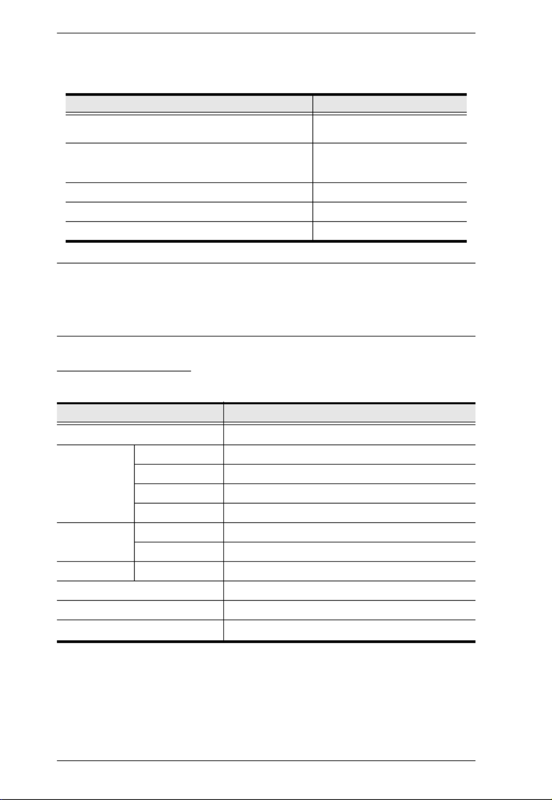
The similarities and differences among the models in the KL1508Ai /
KL1516Ai series are shown in the following table:
The LCD and keyboard/touchpad modules slide independently of each other.
To maximize space in your data center, the keyboard/touchpad module slides
back to "hide away" when not in use, while the thin profile LCD monitor
rotates back – flush against the rack – allowing convenient monitoring of
computer activity.
The KL1508Ai / KL1516Ai features IP-based connectivity that allows one
local operator and multiple remote operators to concurrently monitor and
access the computers on your installation. Because it uses TCP/IP for its
communications protocol, the KL1508Ai / KL1516Ai can be accessed from
any computer on the LAN, WAN, or Internet – whether that computer is
located down the hall, down the street, or halfway around the world.
Model LCD Panel Ports
KL1508AiM 17" 8
KL1508AiN 19" 8
KL1516AiM 17" 16
KL1516AiN 19" 16

KL1508Ai / KL1516Ai User Manual
2
By daisy chaining up to 15 additional switches, as many as 256 computers can
be controlled from the original KVM console. An auto-sensing function
recognizes the position of each station on the chain, eliminating the need to
manually set the position, and a two digit seven-segment LED display on the
keyboard module showing each station's position for easy identification.
Compact, high-density, RJ-45 connectors and CAT 5e/6 cable make for a
compact, efficient, wiring configuration, while the use of PS/2 and USB KVM
Adapter Cables to link to the computers, permits any combination of PCs,
Macs, Sun computers, and serial devices to coexist on the installation.
For added convenience, ports for an external keyboard, monitor, and mouse are
provided on the rear panel – permitting you to manage the switch from a local
console. There is also an external USB mouse port on the keyboard module,
allowing you to use an external mouse, rather than the touchpad.
Access to any computer connected to the installation from the local console is
easily accomplished by means of a powerful mouse driven graphical OSD (On
Screen Display) menu system. A convenient Auto Scan feature also permits
automatic scanning and monitoring of the activities of all computers running
on the installation one by one.
Remote operators connect to the KL1508Ai / KL1516Ai via its IP address from
anywhere on the LAN, WAN, or Internet via their browsers. Once they
successfully log in, they can take control using either the Windows Client or
Java Client utility. Inclusion of a Java-based client ensures that the KL1508Ai

Chapter 1. Introduction
3
/ KL1516Ai is platform independent, and is able to work with most operating
systems.
System administrators can handle a multitude of maintenance tasks smoothly
and efficiently – from installing and running GUI applications, to BIOS level
troubleshooting, routine monitoring, concurrent maintenance, system
administration, rebooting and even pre-booting functions – all from a remote
connection.
Remote operators can exchange keyboard, video and mouse signals with the
computers attached to the KL1508Ai / KL1516Ai just as if they were present
locally and working on the equipment directly.
Enhanced features include a Panel Array Mode that displays the video output
of up to 8 (KL1508Ai) or 16 (KL1516Ai) computers at the same time, and a
Message Board that allows logged in users to conveniently and instantly
communicate with one other – no matter where in the world they actually are.
Setup is fast and easy - plugging cables into their appropriate ports is all that is
entailed. Because the KL1508Ai / KL1516Ai intercepts keyboard input
directly, there is no need to get involved in complex installation routines or to
be concerned with incompatibility problems.
Since the KL1508Ai / KL1516Ai's firmware is upgradable over the Internet,
you can stay current with the latest functionality improvements simply by
downloading firmware updates from our website as they become available.
With its advanced security features, the KL1508Ai / KL1516Ai is the fastest,
most reliable, most cost effective way to remotely access and manage widely
distributed multiple computer installations.

KL1508Ai / KL1516Ai User Manual
4
Features
Hardware
Integrated KVM console with 17” or 19” LED-backlit LCD monitor in a
Dual Rail housing
Exclusive LED illumination light – designed by ATEN to illuminate the
keyboard and touchpad to allow visibility in low-light conditions
A single console controls up to 8 (KL1508Ai) or 16 (KL1516Ai)
computers
Daisy chain up to 15 additional KVM switches to control up to 256
computers*
One bus for remote KVM over IP access
Space-saving RJ-45 connectors and Cat 5e/6 cabling
KVM adapter cables designed with automatic conversion to allow flexible
interface combinations (PS/2, USB, Sun and serial) to control all computer
types
Extra console port – manage computers in the LCD KVM switch from an
external console (monitor, USB or PS/2 keyboard, and USB or PS/2
mouse)
Multiplatform support: PC, Mac, Sun and Serial
Supports external USB mouse
Dual Rail housing is slightly less than 1U with top and bottom clearance
for smooth operation in 1U of rack space
Dual Rail – LCD monitor slides independently of the keyboard/touchpad
LCD module rotates up to 120 degrees for a more comfortable viewing
angle
Console lock – enables the console drawer to remain securely locked away
in position when not in use
LCD power button helps save energy and prolong displays’ life
*Compatible KVM switches: KH1508A/KH1516A, KH0116, ACS1208A/
ACS1216A, CS1708A/CS1716A, KH1508/KH1516
Management
Up to 64 user accounts – up to 32 concurrent remote logins
End session feature – administrators can terminate any running session

Chapter 1. Introduction
5
Adapter ID – stores port information allowing administrators to relocate
servers to different ports, without having to reconfigure the adapters and
switch
Port Share Mode allows multiple users to gain access to a server
simultaneously
Remote power control for attached Power Over the NET™ devices
Integration with ALTUSEN CC2000 Management software
Event logging and Windows-based Log Server support
Local Log Event
Firmware upgradeable
IPv6 capable
Easy-to-Use Interface
Easy computer selection via pushbuttons, Hotkey Mode, OSD (On-Screen
Display), and Browser-based GUI
Local Console, Browser, and AP GUIs offer a unified multi language
interface to minimize user training time and increase productivity
Multiplatform client support (Windows, Mac OS X, Linux, Sun)
Multi-browser support: Internet Explorer, Chrome, Firefox, Safari, Opera,
Mozilla, Netscape
Browser-based UI in pure Web technology allows administrators to
perform administrative tasks without the need for Java to be pre-installed
Panel Array Mode™
Keyboard broadcast* – keyboard input can be duplicated on all the
attached servers
Keyboard Language support: English (US); English (UK); German;
German (Swiss); French; Spanish; Traditional Chinese; Japanese; Korean;
Swedish; Italian; Russian; Hungarian and Greek
*Local Console only
Advanced Security
Remote authentication support: RADIUS, LDAP, LDAPS, and MS Active
Directory
Supports TLS 1.2 encryption and RSA 1024-bit certificates to secure user
logins from browsers

KL1508Ai / KL1516Ai User Manual
6
Flexible encryption design allows users to choose any combination of 56-
bit DES, 168-bit 3DES 256-bit AES, 128-bit RC4, or Random for
independent KB/Mouse, and video data encryption
IP/MAC Filter support for enhanced security protection
Configurable user and group permissions for server access and control
Virtual Remote Desktop
Video quality and video tolerance can be adjusted to optimize data transfer
speed; monochrome color depth setting, threshold and noise settings for
compression of the data bandwidth in low bandwidth situations
Full-screen or sizable and scalable Virtual Remote Desktop
Message board feature allows logged in users to communicate with each
other
Mouse DynaSync™ – automatically synchronizes the local and remote
mouse movements
On-screen keyboard with multi language support
BIOS-level access

Chapter 1. Introduction
7
Requirements
General
We recommend computers with at least a P 4 2GHz processor, and 1 GB
RAM.
Browsers must support TLS 1.2 encryption.
A network transfer speed of at least 512kbps is recommended.
For the Log Server, you must have the Microsoft Jet OLEDB 4.0 or higher
driver installed.
External Console
A VGA, SVGA, or Multisync monitor capable of the highest resolution
that you will be using on any computer in the installation.
A USB or PS/2 style mouse
A USB or PS/2 style keyboard
Computers
The following equipment must be installed on the computers that connect to the
KL1508Ai or KL1516Ai's KVM ports:
A VGA, SVGA or Multisync port
A Type A USB port and USB host controller (for USB KVM Adapter
Cable Connection, see below)
6-pin mini-DIN keyboard and mouse ports (for PS/2 KVM Adapter Cable
Connection, see below)
Note: The integrated LCD monitor’s maximum screen resolution is 1280
x 1024 @ 75 Hz. If you want to use a higher setting for the screen
resolutions of the attached computers, see Screen Resolutions
Higher than 1280 x 1024, page 206.
KVM Adapter Cables
Cat 5e/6 cable is required to connect the KL1508Ai / KL1516Ai to one of the
KVM adapter cables.
KL1508Ai / KL1516Ai User Manual
8
The following KVM adapter cables are required for use with the KL1508Ai /
KL1516Ai:
Note: 1. KVM adapter cables are referred to as I/O Modules in some dialog boxes.
2. The following cable models support the Adapter Cable ID function:
KA7920 / KA7970 / KA7520 / KA7570 / KA7120 / KA7130 / KA7166
/ KA7168 / KA7169 / KA7170.
Operating Systems
Supported operating systems are shown in the table, below:
1 Does not support USB. 2 Kernels below 2.6 do not support USB 2.0
Function Module
Connect to devices with PS/2 ports KA7920 / KA7520 / KA7120
KA9520 / KA9120
Connect to devices with USB ports KA7970 / KA7570 / KA7166 /
KA7168 / KA7169 / KA7170
KA9570 / KA9170
Connect to Sun Legacy systems (with 13W3 port) KA9130 / KA7130
Connect to Sun USB systems KA9170 / KA7170
Connect to serial based devices KA9140
OS Version
Windows NT1, Server 2003, Server 2008, 2000 and higher
Linux2RedHat 9.0, Fedora and higher, RHEL AS 4, RHEL 5
SuSE 10 and higher, OpenSUSE 10.2; SLES 10 SP1
Debian 3.1, 4.0
Ubuntu 7.04, 7.10
UNIX IBM AIX4.3, 5L (V5.2,V5.3), V6 (V6.1)
FreeBSD 5.5, 6.1, 6.2
Novell Netware 5.0 and higher
Sun Solaris 8, 9, 10
Mac 9.0, 9.1, 10.1, 10.2, 10.3, 10.4 , 10.5
DOS 6.2 and higher1
Chapter 1. Introduction
9
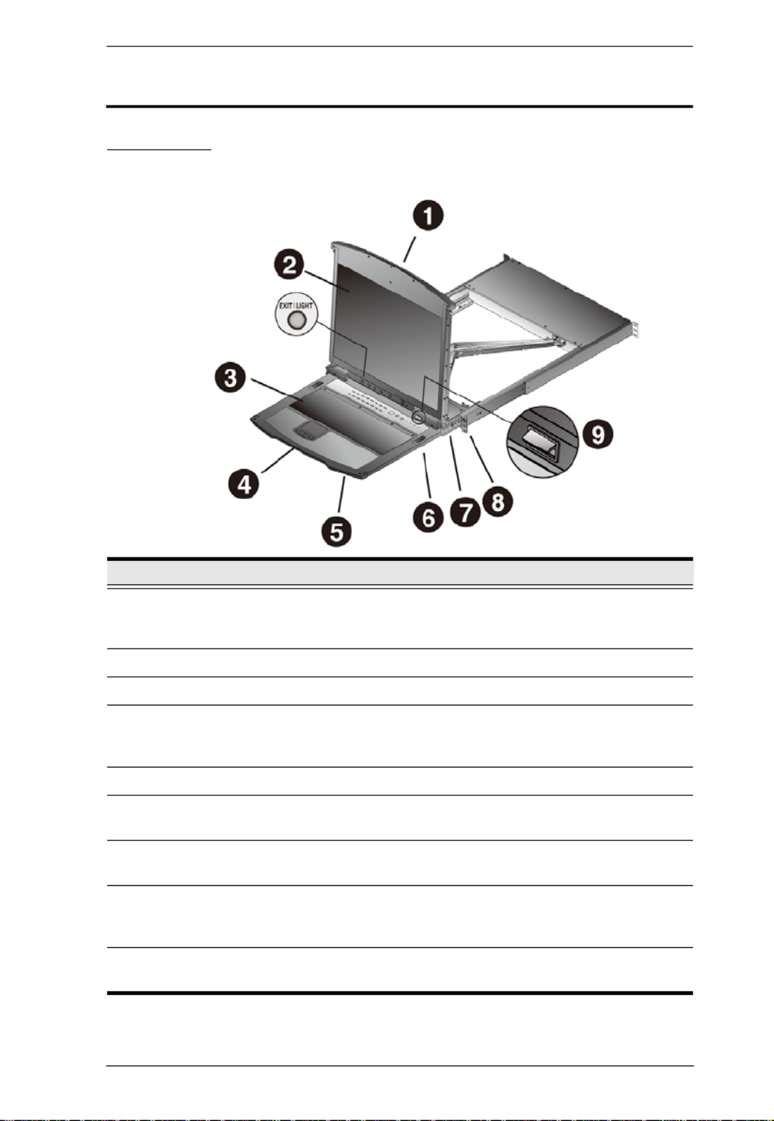
Components
Front View
No. Component Description
1 Upper Handle Pull to slide the LCD module out; push to slide the module in.
See Opening the Console, page 23, for details on sliding the
console in and out.
2 LCD Module See LCD Module, page 11.
3 Keyboard Module See Keyboard Module, page 10.
4 Lower Handle Pull to slide the keyboard module out. See Opening the
Console, page 23, for more details on sliding the console in
and out.
5 Power LED Lights (blue) to indicate that the unit is receiving power.
6 Keyboard
Release Catch
These catches (one on each side) release the keyboard
module so you can slide it away.
7 LCD Release
Catch
These catches (one on each side) release the LCD module
so you can slide it away.
8 Rack Mounting
Tabs
The rack mounting tabs located at each corner of the unit
secure the chassis to a system rack. See Standard Rack
Mounting, page 14, for details.
9 LED Illumination
Light
Illuminates the keyboard and touchpad to allow visibility in
low-light conditions.
KL1508Ai / KL1516Ai User Manual
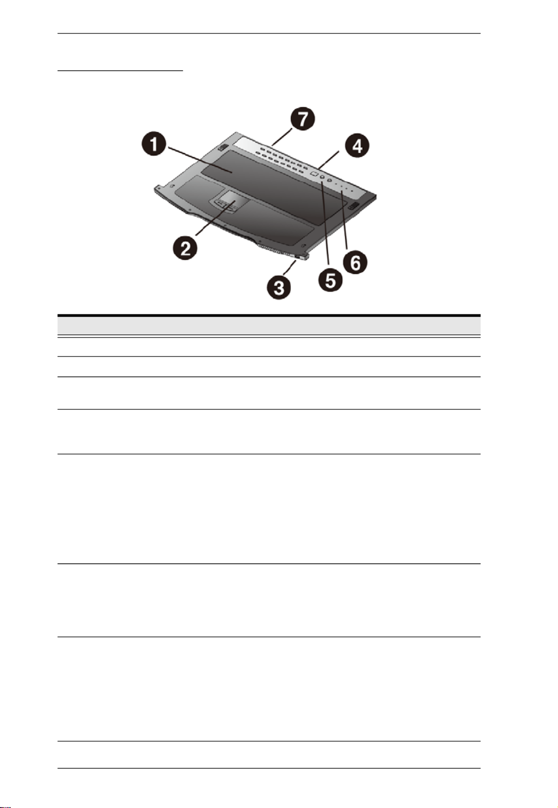
10
Keyboard Module
No. Component Description
1 Keyboard Standard 105-key keyboard
2 Touchpad Standard mouse touchpad
3 External Mouse
Port
This USB-type mouse port is provided for users who prefer to
use an external mouse.
4 Station ID LED In a daisy chained installation, the Station ID of the currently
selected station displays as a 2-digit figure in this
panel.See Port ID Numbering, page 33 for further details.
5 Station Selection
Area The LED displays the station number that the port with the
KVM focus is located on.
The left button shifts the KVM focus down the chain
(Station 2
→ Station 1, etc.). After Station 1, it cycles back
to the last Station.
The right button shifts the KVM focus up the chain. After the
last Station, it cycles to Station 1.
6 Lock LEDs &
Reset Switch
The Num Lock, Caps Lock, Scroll Lock LEDs are located
here.
A Reset Switch is located just to the right of the Lock LEDs.
Press this recessed switch in with a thin object to perform a
system reset.
7 Port Selection
Buttons and
LEDs
To access a Port on the currently selected Station press its
corresponding port selection button. Indicator LEDs are built
into the switches:
An On Line LED lights to indicate that the computer
attached to its corresponding port is up and running.
A Selected LED lights to indicate which port has the KVM
focus.
Chapter 1. Introduction
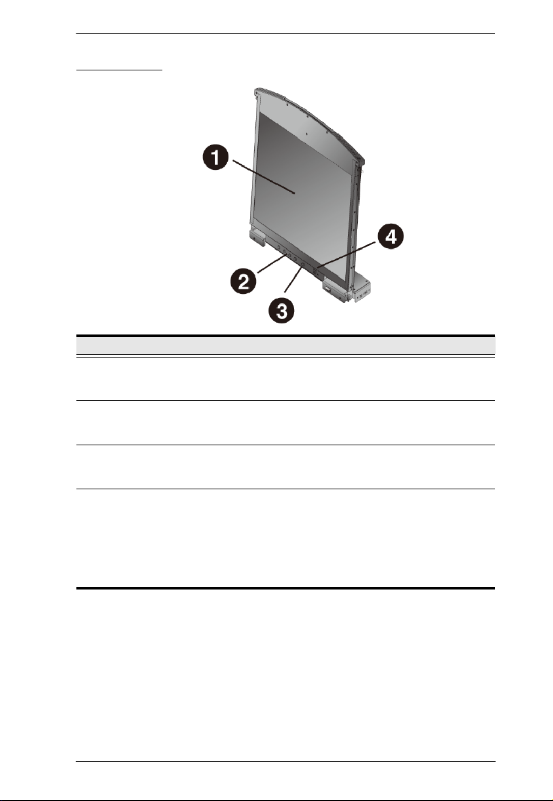
11
LCD Module
No. Component Description
1 LCD Display To access the LCD monitor, slide the LCD module out and flip
up the cover. See , page 23, for details Opening the Console
on sliding the LCD module out.
2 LCD Controls These buttons control the position and picture settings of the
LCD display. See LCD OSD Configuration, page 29, for
details.
3 LCD On/Off
Button
Push this button to turn the LCD monitor on and off. The
button lights when the LCD monitor is off to indicate that only
the monitor is off – not the KVM switch itself.)
4 Firmware
Upgrade Section
Firmware Upgrade Port: The Firmware Upgrade Cable that
transfers the firmware upgrade data from the administrator's
computer to the KL1508Ai / KL1516Ai plugs into this RJ-11
connector.
Firmware Upgrade Switch: During normal operation this
switch should be in the NORMAL position. (See The Firmware
Upgrade Utility, page 159 for firmware upgrading details.)

KL1508Ai / KL1516Ai User Manual
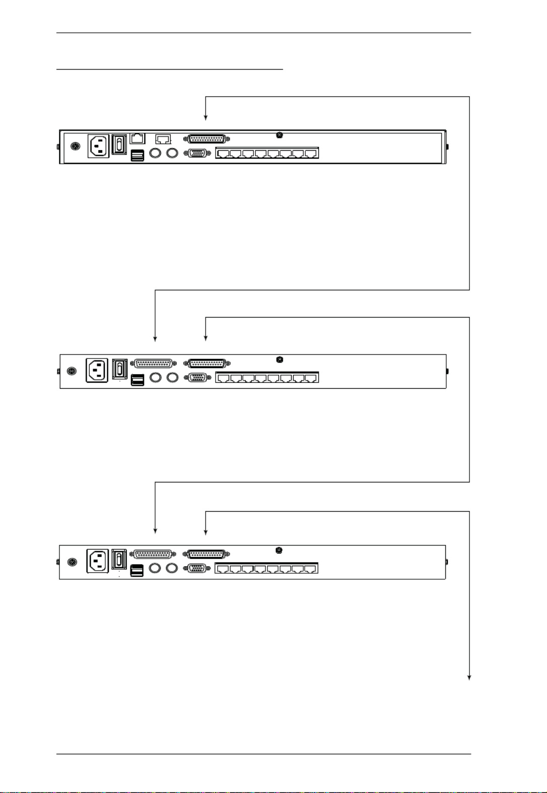
12
Rear View
* The KL1516Ai is pictured above. The KL1508Ai rear panel is the same as
that of the KL1516Ai, except that it has 8 KVM ports instead of 16.
No. Component Description
1 Grounding
Terminal
The grounding wire used to ground the switch attaches here.
2 Power Socket This is a standard 3-pin AC power socket. The power cord
from an AC source plugs in here.
3 Power Switch This is a standard rocker switch that powers the unit on and
off.
4 LAN Port The cable that connects the to the LAN plugs in here. The
LEDs indicate data transmission speed: ORANGE: 10 Mbps /
GREEN: 100 Mbps
5 PON Port This connector is provided for a Power over the Net™ (PON)
unit to plug into. A PON device allows computers attached to
the KL1508Ai / KL1516Ai to be booted remotely over the net.
Contact your dealer for more details.
6 Daisy Chain Port When Daisy Chaining Units (See , page 20), Daisy Chaining
the daisy chain cable plugs in here.
7 Local Console
Port Selection
If this is a Single Station installation, or if this is the First
Station of a daisy chained installation, the keyboard, monitor,
and the mouse that make up the Local Console plug in here.
8 KVM Port
Selection
The Cat 5e/6 cables that link to the KVM Adapter Cables
(which link to the computers) plug in here.
5
2346
87
1

13
Chapter 2
Hardware Setup
Before You Begin
1. Important safety information regarding the placement of this
device is provided on page 187. Please review it before
proceeding.
2. Make sure that power to all the devices you will be connecting
up has been turned off. You must unplug the power cords of any
computers that have the Keyboard Power On function.
3. Packing material has been inserted to protect the KL1508Ai /
KL1516Ai during shipping. Slide the LCD module out (see
Opening the Console, page 23), until the packing material is
visible. Remove the packing material before installing the unit,
as shown in the diagram below.

KL1508Ai / KL1516Ai User Manual
14
Standard Rack Mounting
A standard rack mounting kit is provided with your KL1508Ai / KL1516Ai.
The kit enables the switch to be mounted in a rack with a depth of 42–77 cm.
Note: 1. It takes two people to mount the switch: one to hold it in place, the
other to screw it in.
2. The standard rack mounting kit does not include screws or cage nuts.
If you need additional screws or cage nuts, contact your rack dealer.
3. Optional mounting kits – including single person Easy Installation
kits – are available with a separate purchase. See Optional Rack
Mounting, page 213, for details.
L Brackets
Side Mountng
Brackets
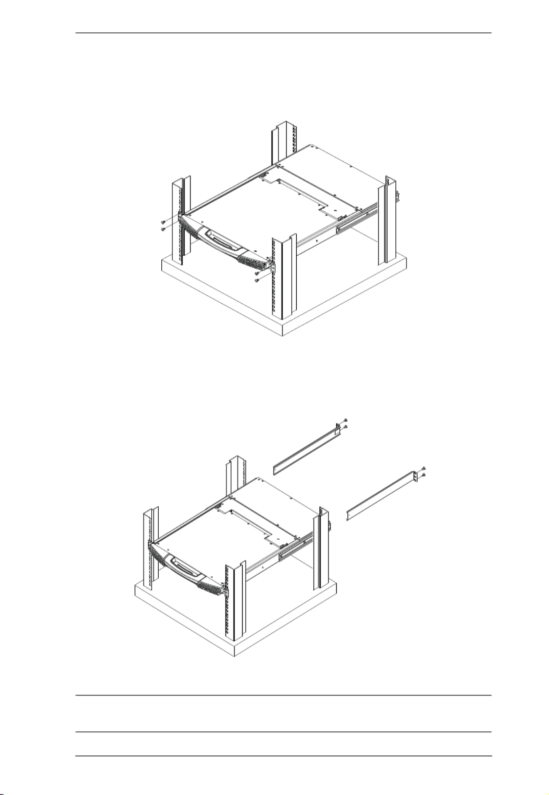
Chapter 2. Hardware Setup
15
To rack mount the switch, do the following:
1. While one person positions the switch in the rack and holds it in place, the
second person loosely screws the front brackets to the rack.
2. While the first person still holds the switch in place, the second person
slides the L brackets into the switch's side mounting brackets, from the
rear until the bracket flanges contact the rack, then screws the L brackets
to the rack.
3. After the L brackets have been secured, tighten the front bracket screws.
Note: Allow at least 5.1 cm on each side for proper ventilation, and at least
12.7 cm at the back for the power cord and cable clearance.

KL1508Ai / KL1516Ai User Manual
16
Single Stage Installation
In a Single Stage installation, there are no additional switches daisy chained
down from the first unit. To set up a single stage installation, refer to the
installation diagrams beginning on the following page (the numbers in the
diagram correspond to the numbers of the installation steps), and do the
following:
1. Ground the KL1508Ai / KL1516Ai by connecting one end of a grounding
wire to the grounding terminal, and the other end of the wire to a suitable
grounded object.
Note: Do not omit this step. Proper grounding helps to prevent damage to
the unit from surges or static electricity.
2. If you choose to install an external console, plug your keyboard, monitor,
and mouse into the Console Ports located on the switch’s rear panel. The
ports are color coded and marked with an icon to identify themselves.
Note: This step is optional.
3. For each of the computers you are installing, use Cat 5e cable to connect
any available KVM port to a KVM adapter cable that is appropriate for the
computer you are installing. (See KVM Adapter Cables, page 7, for
adapter cable details.)
Note: The maximum supported distance to the adapter cable is 50 m.
4. Connect the KVM Adapter cable to the computer. Refer to the KVM
Adapter Cable Installation Diagram, page 18, to plug the adapter cable
connectors into their respective ports on the computers you are installing.
5. Plug the LAN or WAN cable into the KL1508Ai / KL1516Ai’s LAN port.
6. Connect the power cord to the switch and to an AC power source.
After the KL1508Ai / KL1516Ai is cabled up, you can turn on the power. After
the switch is powered up, you can turn on the servers.

Chapter 2. Hardware Setup
17
Single Stage Installation Diagram
5 4
1
2
by A
TEN
PS/2 CPU MODUL E
MO
DEL NO.
KA9120
PS/2 CPU MODUL E
MO DEL
NO.
KA9120
LINK
3
2
3
6

KL1508Ai / KL1516Ai User Manual
18
KVM Adapter Cable Installation Diagram
KA7120
KA7520
KA7920
KA9120
KA9520
by ATEN
LINK
KA7170
KA7570
KA7970
KA9170
KA9570
by ATEN
LINK
KA9140
SERIAL TERMINAL
KA7130
KA9130
by ATEN
LINK

Chapter 2. Hardware Setup
19
KVM Adapter Cable Installation Diagram cont.
KA7166
KA7168
KA7169

KL1508Ai / KL1516Ai User Manual
20
Daisy Chaining
To control even more computers, up to 15 additional compatible KVM
switches can be daisy chained from the original KL1508Ai or KL1516Ai. As
many as 256 computers can be controlled from a single console in a complete
installation.
Note: Since it would be unnecessarily wasteful and expensive to use
KL1508Ai / KL1516Ai switches for daisy chaining (there is no point in
having consoles on the chained switches), switches without LCD
consoles are used instead. Please see the table, Supported Devices,
page 211 for a list of ATEN switches that can be installed on a
KL1508Ai / KL1516Ai daisy chain.
Tables showing the relation between the number of computers and the number
of KL1508Ai / KL1516Ai units needed to control them are provided on
page 210.
To set up a daisy chained installation, make sure that power to all the devices
you will be connecting up has been turned off, and refer to the Daisy Chain
Installation Diagram, page 22 as you do the following:
1. Use a daisy chain cable set to connect the Chain Out port of the parent
KL1508Ai / KL1516Ai unit to the Chain In port of the child compatible
KVM Switch unit (first station out to second station in, second station out
to third station in, etc.).
Note: 1. You cannot use the chain in port of the First Station, since it is the
highest level parent.
2. Daisy chain cable sets require a separate purchase. See your
dealer for details.
2. Cable up the computers and the switch according to the information
provided under Single Stage Installation, page 16.
3. Repeat the above for any other switches you want to add to the chain.
4. Power up the installation according to the following procedure:
a) Plug in the power cord for the first station. Wait for the unit to ascertain
its station ID and display it on the Station ID LED. (The station ID for
the first stage unit is 01, the ID for the second stage unit is 02, the ID for
the third stage unit is 03, etc.)

Chapter 2. Hardware Setup
21
b) Power on each station on the installation in turn (second station, then
third station, etc.). In each case, wait for the station ID to be ascertained
and displayed before powering on the next station.
c) After all the stations are up, power on the computers.
KL1508Ai / KL1516Ai User Manual
22
Daisy Chain Installation Diagram
23
Chapter 3
Basic Operation
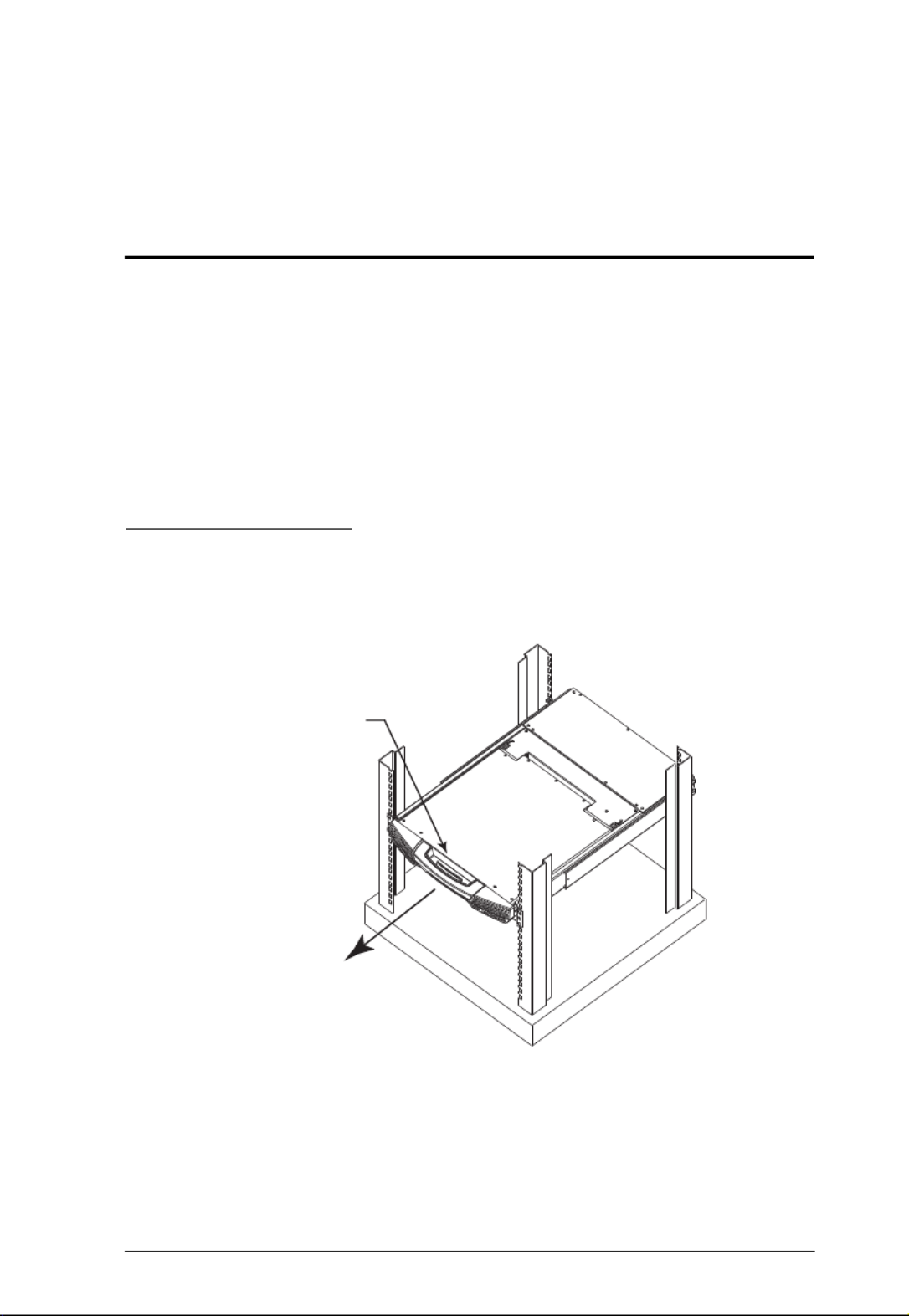
Opening the Console
The KL1508Ai / KL1516Ai's console consists of two modules: an LCD display
module located under the top cover; and a keyboard/touchpad module below
the LCD module.
The modules can either slide together, or independently. This allows you to
have the LCD display available for viewing while the keyboard/touchpad
module is conveniently out of the way when not in use.
Opening Separately
1. Pull the release catch to release the console, and pull the top panel a few
centimeters toward you. Once the console has been released, you can let
go of the catch.
(Continues on next page.)
Release Catch

KL1508Ai / KL1516Ai User Manual
24
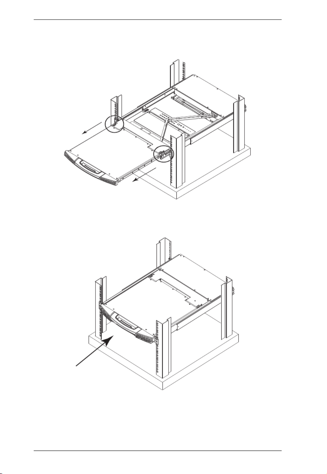
(Continued from previous page.)
2. Pull the top panel all the way out until it clicks into place.
3. Rotate the top panel all the way back to expose the LCD screen.

Chapter 3. Basic Operation
25
4. Reach underneath and pull the keyboard module all the way out until it
clicks into place.
Opening Together
Refer to the diagrams in the Opening Separately section as you do the
following:
1. Pull the release catch and pull the top and bottom panels out until the
keyboard module clicks into place.
Note: Once the console has been released, you can let go of the catch.
2. Pull the top panel the rest of the way out until it clicks into place.
3. Rotate the top panel all the way back to expose the LCD screen.
Note: Refer to the warning regarding placing excessive weight on the
keyboard module on the following page.

KL1508Ai / KL1516Ai User Manual
26
Operating Precautions
RIGHT
Rest your hands and arms lightly on the
keyboard module as you work.
WRONG!
DO NOT lean your body weight on the
keyboard module.
DO NOT place heavy objects on the
keyboard module.
The maximum load bearing capacity of the keyboard module is
30kg. Failure to heed the information below can result in damage
to the keyboard module.

Chapter 3. Basic Operation
27
Closing the Console
1. Pull the release catches located on either side of the keyboard toward you
to release the keyboard module, then slide the module slightly in.
2. Let go of the catches. Using the front handle, push the keyboard module
all the way in.
KL1508Ai / KL1516Ai User Manual
28
3. Rotate the LCD module all the way down, then pull the rear catches to
release the LCD module.
4. Using the front handle, push the module all the way in.

Chapter 3. Basic Operation
29
LCD OSD Configuration
The LCD Buttons
The LCD OSD allows you to set up and configure the LCD display. Four
buttons (see LCD Controls, page 11), are used to perform the configuration, as
described in the table below:
Button Function
MENU When you have not entered the LCD OSD Menu
function, pressing this button invokes the Menu
function and brings up the Main Menu.
When navigating through the menus, this button
moves you right or up. When making an adjustment, it
increases the value.
When navigating through the menus, this button
moves you left or down. When making an adjustment,
it decreases the value.
EXIT When you have not entered the LCD OSD Menu
function, pressing this button performs an auto
adjustment. An auto adjustment automatically
configures all the settings for the LCD panel to what
the OSD considers their optimum values to be.
When you have entered the LCD OSD Menu
function, pressing this button exits the current menu
and returns you to the previous menu. Use it to
leave an adjustment menu when you are satisfied
with the adjustment you have made.
When you are at the Main Menu, pressing this
button exits the LCD OSD.

KL1508Ai / KL1516Ai User Manual
30
The Adjustment Settings
An explanation of the LCD OSD adjustment settings is given in the table
below:
Setting Explanation
Brightness Adjusts the background black level of the screen image.
Contrast Adjusts the foreground white level of the screen image.
Phase If pixel jitter or horizontal line noise is visible on the display, your
LCD may have the wrong phase setting. Adjust the phase setting
to eliminate these problems.
Clock If vertical banding is visible on the display, your LCD may have
the wrong clock setting. Adjust the clock setting to eliminate
vertical banding.
H-Position Positions the display area on the LCD panel horizontally (moves
the display area left or right).
V-Position Positions the display area on the LCD panel vertically (moves
the display area up or down).
Color Temperature Adjusts the color quality of the display. You can adjust the
“warmth” value, color balance, etc. The Adjust Color selection
has a further submenu that lets you fine tune the RGB values.
Language Selects the language that the OSD displays its menus in.
OSD Duration Lets you set the amount of time that the OSD displays on the
screen. If there is no input for the amount of time you choose, the
OSD display turns off.
Reset Resets the menu and submenu adjustments (except for
language settings) to the original factory default settings.

Chapter 3. Basic Operation
31
Port Selection
KL1508Ai / KL1516Ai installations provide three methods to obtain instant
access to any computer in your installation: Manual, OSD/GUI, and Hotkey.
Manual
For manual port selection, simply press the Port Switch that corresponds to the
device you wish to access.
OSD / GUI
The KL1508Ai / KL1516Ai provides menu driven interfaces to the computer
switching procedure. There are two systems: A text-based OSD when you log
in from the local console; and a graphical user interface (GUI) when you log in
remotely over the internet. Local console OSD operation is discussed in the
next chapter; GUI operation is discussed from Chapter 5 onwards for Internet
browser, and Windows and Java logins.
Hotkeys
Hotkeys allow you to conveniently provide KVM focus to a particular
computer from the local console keyboard, instead of having to manually select
them by pressing Port Selection switches. See Hotkey Port Control, page 49,
for details.

KL1508Ai / KL1516Ai User Manual
32
Hot Plugging
The KL1508Ai / KL1516Ai supports hot plugging – components can be
removed and added back into the installation by unplugging and replugging
their cables from their ports without the need to shut the unit down. In order for
hot plugging to work properly, however, the procedures described below must
be followed.
Hot Plugging Stations
You can switch station positions by simply unplugging from the old parent and
plugging into a new one. After you do, in order for the OSD menus to
correspond to the change, you must reset the OSD. See RESET STATION IDS,
page 44, for details.
Hot Plugging KVM Ports
After switching KVM ports, in order for the OSD menus to correspond to the
change, you must manually reconfigure the OSD information for the new Port
information. See F3: SET, page 40, and the Port Setting selections under the
F4 ADM function, page 43, for details.
Note: If the computer’s Operating System doesn’t support hot plugging, this
function may not work properly.
Hot Plugging Console Ports
Keyboard, monitor, and mouse can all be hot plugged. When hot plugging
the mouse:
You may unplug the mouse and plug it back in again (to reset the mouse,
for example), as long as you use the same mouse.
If you plug in a different mouse, all the stations and all the computers on
the installation must be shut down for 10 seconds, then restarted following
the Power Up Sequence described under Step 6 on page 20.
Some older operating systems may not support hot-plugging.
Note: If, after hot plugging (or at any other time), there is no response to
keyboard and/or mouse input, perform a Keyboard and Mouse Reset
by pressing in the Reset switch (see page 55).

Chapter 3. Basic Operation
33
Powering Off and Restarting
If it becomes necessary to power off the KL1508Ai / KL1516Ai, or if the
switch loses power and needs to be restarted, before starting it back up you
must follow these procedures:
1. Shut down all the computers that are attached to it.
Note: You must unplug the power cords of any computers that have the
Keyboard Power On function.
2. Wait 10 seconds then power it back on. If you have shut down more than
one station, power up the highest station first and work your way down to
the lowest one. Wait for each station to display its Station ID on the front
panel LED before powering on the next one.
3. After the station(s) is (are) up, power the computers back on.
Port ID Numbering
Each computer on the installation is assigned a unique Port ID. The Port ID is
a one or two segment number that is determined by the Stage Level and KVM
Port number of the KVM switch that the computer is connected to.
The first segment represents the KVM Port number of the First Stage unit; the
second segment represents the KVM Port number of the Second Stage unit.
A computer attached to a First Stage unit has a one segment Port ID (from 1–
16) that corresponds to the KVM Port number that it is connected to.
A computer attached to a Second Stage unit has a two segment Port ID:
The second segment (from 1–16), represents the KVM Port number on the
Second Stage unit that the computer is connected to. The first segment
(from 1–16) represents the KVM Port number on the First Stage unit that
the Second Stage unit links back to.
For example, a Port ID of 12–3 refers to a computer that is connected to
KVM Port 3 of a Second Stage unit that links back to KVM Port 12 of the
First Stage unit.

KL1508Ai / KL1516Ai User Manual
34
This Page Intentionally Left Blank

35
Chapter 4
OSD Operation
OSD Overview
The On Screen Display (OSD) is a menu driven method to handle computer
control and switching operations. All procedures start from the OSD Main
Screen. To display the Main Screen, tap the OSD hotkey twice.
The default hotkey is [Scroll Lock]. You can change the hotkey to the Ctrl key
or the Alt key if you like (see OSD HOTKEY, page 40).
Note: 1. If you use the Ctrl or Alt key method you must press the same Ctrl or
Alt key both times.
2. Once you start the OSD, the keyboard lock will be controlled by the
device. The number lock and caps lock will always be on when the
OSD is being accessed.
The OSD incorporates a two level (administrator / user) password system.
Before the OSD Main Screen comes up, a login dialog box appears that asks
for a username and password. You must provide a valid username and
password in order to continue.
The first time that the OSD is accessed, you must use the default username and
password. The default username is administrator; the default password is
password. For security purposes, we strongly recommend changing these to
something unique after you log in for the first time.
After logging in with the default username and password, the OSD Main
Screen opens in Administrator mode. In this mode, you have administrator
privileges, with access to all administrator and user functions, and can set up
operations (including password authorization for the future), as you would like.

KL1508Ai / KL1516Ai User Manual
36
When you invoke the OSD, a screen similar to the one below appears:
Note: The diagram depicts the Administrator's Main Screen. The User Main
Screen does not show the F4 and F6 functions, since these are reserved
for the administrator and can't be accessed by ordinary users.
Manufacturing Number
The “MFG Number” (Manufacturing Number) is an internal serial number
used by ATEN’s factory and technical support staff to identify products. This
number does not affect products’ warranty. If your product requires after-sales
services, you may provide the MFG Number to ATEN’s sales or technical
support staff to identify the product and model number.

Chapter 4. OSD Operation
37
OSD Navigation
To dismiss the menu, and deactivate the OSD, click the X at the upper
right corner of the OSD Window or press Esc.
To Logout click F8 or the
ZZZ symbol at the top of the Main Screen, or
press [F8].
The OSD uses a tree view. To see the ports for a particular station, click
the plus sign [ + ] in front of the station number. The port number list
drops down. To dismiss the list, click the circle symbol [ o ] in front of the
station number.
To move up or down through the list one line at a time, click the up and
down triangle symbols (ST) or use the up and down arrow keys. If there
are more list entries than there is room for on the Main Screen, the screen
will scroll.
To move up or down through the list one screen at a time, click the up and
down arrow symbols (ÏÐ), or use the [Pg Up] and [Pg Dn] keys. If there
are more list entries than there is room for on the Main Screen, the screen
will scroll.
To bring the KVM focus to a port, double-click it, or move the highlight
bar to it and then press [Enter].
After executing any action, you automatically go back to the menu one
level above.
OSD Main Screen Headings
Heading Explanation
SN-PN This column lists the port ID numbers (station number-port number) for
all the KVM ports on the installation. The simplest method to access a
particular computer is to click it, or move the highlight bar to it, and then
press [Enter].
QV If a port has been selected for Quick View scanning (see SET QUICK
VIEW PORTS, page 42), an arrowhead displays in this column.
The computers that are powered on and are online have a sun symbol
in this column.
NAME If a port has been given a name (see EDIT PORT NAMES, page 43), its
name appears in this column.

KL1508Ai / KL1516Ai User Manual
38
OSD Functions
OSD functions are used to configure and control the OSD. For example, you
can rapidly switch to any port, scan selected ports only, limit the list you wish
to view, designate a port as a Quick View Port, create or edit a port name, or
make OSD setting adjustments.
To access an OSD function:
1. Either click a function key field at the top of the Main Screen, or press a
function key on the keyboard.
2. In the submenus that appear make your choice either by double clicking it,
or moving the highlight bar to it, and then pressing [Enter].
3. Press [Esc] to return to the previous menu level.
F1: GOTO
Accessing the GOTO function allows you to switch directly to a port either by
keying in the port's name or its port ID.
To use the Name method, key in 1, key in the port's name, and then press
[Enter].
To use the Port ID method, key in 2, key in the port ID, and then press
[Enter].
Note: You can key in a partial name or port ID. The screen will show all the
computers that the user has View rights to that match the name or port
ID pattern, regardless of the current List settings (see F2: LIST, page 39,
for details).
To return to the OSD Main Menu without making a choice, press [Esc].

Chapter 4. OSD Operation
39
F2: LIST
Many of the switch’s OSD functions only operate on the computers currently
selected for listing on the Main Screen. Accessing this function lets you
broaden or narrow the scope of ports that get listed. The submenu choices and
their meanings are given in the table below:
Move the highlight bar to the choice you want, then press . An icon [Enter]
appears before the choice to indicate that it is the currently selected one.
Choice Meaning
ALL Lists all of the ports on the installation.
QUICK VIEW Lists only the ports that have been selected as Quick View Ports
(see SET QUICK VIEW PORTS, page 42).
POWERED ON Lists only the ports that have attached computers Powered On.
QUICK VIEW +
POWERED ON
Lists only the ports that have been selected as Quick View Ports
(see SET QUICK VIEW PORTS, page 42), and that have their
attached computers Powered On.

KL1508Ai / KL1516Ai User Manual
40
F3: SET
Accessing this function allows the administrator and each user to set up an
individual working environment. A separate profile for each operator is stored
by the OSD and is activated according to the username provided during login.
To change a setting:
1. Double-click it; or move the highlight bar to it, then press [Enter].
2. After you select an item, a submenu with further choices appears. To make
a selection, either double click it; or move the highlight bar to it, then press
[Enter]. An icon appears before the selected choice to indicate which one
it is. The settings are explained in the following table:
Setting Function
OSD
HOTKEY
Selects which hotkey activates the OSD function:
[Scroll Lock] [Scroll Lock]; [Ctrl] [Ctrl] or [Alt] [Alt].
Since the [Ctrl] or [Alt] key combinations may conflict with programs
running on the computers, the default is the [Scroll Lock] combination.
PORT ID
DISPLAY
POSITION
Allows you to position where the port ID appears on the monitor. The
default is the upper left corner, but you can choose to have it appear
anywhere on the screen.
Use the mouse or the arrow Keys plus Pg Up, Pg Dn, Home, End, and
5 (on the numeric keypad with Num Lock off), to position the port ID
display, then click or press [Enter] to lock the position and return to the
Set submenu.
Note: The setting affects the currently selected port. If you don’t want
to use the default position, you must change the setting for each port
individually.
PORT ID
DISPLAY
DURATION
Determines how long a port ID displays on the monitor after a port
change has taken place. There are two choices: 3 seconds and Off.
PORT ID
DISPLAY
MODE
Selects how the port ID is displayed: the port number alone (PORT
NUMBER); the port name alone (PORT NAME); or the port number
plus the port name (PORT NUMBER + PORT NAME). The default is
PORT NUMBER + PORT NAME).
SCAN
DURATION
Determines how long the focus dwells on each port as it cycles through
the selected ports in Auto Scan mode (see F7: SCAN, page 48). Key in
a value from 1–255 seconds, then press . Default is 5 seconds; [Enter]
a setting of 0 disables the Scan function.

Chapter 4. OSD Operation
41
Setting Function
SCAN/SKIP
MODE
Selects which computers will be accessed under Skip mode (see F5:
SKP, page 46), and Auto Scan mode (see F7: SCAN, page 48).
Choices are:
ALL – All the ports which have been set Accessible;
QUICK VIEW – Only those ports which have been set Accessible and
have been selected as Quick View Ports (see SET QUICK VIEW
PORTS, page 42);
POWERED ON – Only those ports which have been set Accessible
and are Powered On;
QUICK VIEW + POWERED ON – Only those ports which have been
set Accessible and have been selected as Quick View Ports and are
Powered On. The default is ALL.
SCREEN
BLANKER
If there is no input from the console for the amount of time set with this
function, the screen is blanked. Key in a value from 1–30 minutes, then
press [Enter]. A setting of 0 disables this function. The default is Off.
HOTKEY
COMMAND
MODE
Enables / Disables the Hotkey function (see OSD Operation, page 35),
in case a conflict with programs running on the computers occurs. The
default is On.
HOTKEY This setting selects the Hotkey invocation keys (see Hotkey Operation,
page 49). Choices are [NUM LOCK] + [-], or [CTRL] + [F12]. The
default is [NUM LOCK] + [-].
OSD
LANGUAGE
Sets the language that the OSD displays in. Choices are: English,
German, Japanese, Simplified Chinese, Traditional Chinese, Spanish,
Russian, and French. The default is English.
SET
CONSOLE
KEYBOARD
Sets the keyboard language mapping of the console keyboard. The
default is Auto. If the switch does not automatically receive language
mapping from the keyboard, it will set to English (US).
SET
LOGOUT
TIMEOUT
If there is no input from the console for the amount of time set with this
function, the operator is automatically logged out. A login is necessary
before the console can be used again.
This enables other operators to gain access to the computers when the
original operator is no longer accessing them, but has forgotten to log
out. To set the timeout value, key in a number from 1–180 minutes,
then press [Enter]. If the number is 0 (zero), this function is disabled.
Default is Off.
ACTIVATE
BEEPER
Choices are Y (for Yes), or N (for No). When activated, the beeper
sounds whenever a port is changed, when activating the Auto Scan
function (see F7: SCAN, page 48), or an invalid entry is made on an
OSD menu. The default is On.
(Continues on next page.)

KL1508Ai / KL1516Ai User Manual
42
(Continued from previous page.)
Setting Function
SET QUICK
VIEW PORTS
This function lets the administrator select which ports to include as
Quick View ports.
To select/deselect a port as a Quick View Port, use the navigation
keys to move the highlight bar to it, then press the [Spacebar].
When a port has been selected as a Quick View Port, an arrowhead
displays in the QV column of the LIST on the Main Screen to
indicate so. When a port is deselected, the arrowhead disappears.
If one of the Quick View options is chosen for the LIST view (see
F2: LIST, page 39), only a port that has been selected here will
display on the List.
If one of the Quick View options is chosen for Auto Scanning (see
SCAN/SKIP MODE, page 41), only a port that has been selected
here will be Auto Scanned.
The default is for no ports to be selected.
PREFERRED
RESOLUTION
This function allows you to set the preferred resolution for a second
external display* connected to the switches console port, which will be
sent to the KVM adapter cables. The KVM adapter cables provide the
connected computer’s video card with EDID information about the
monitor connected to the switch. This affects the video quality
displaying on the external console monitor. Choices are:
MONITOR DEFAULT SETTING – Sends the EDID information
provided by the switches LCD monitor
– to the KVM adapter cable.
Alternative Resolution – Sends the alternative resolution (EDID
information) selected for the external display connected to the
switches console port, to the KVM adapter cables. Select a
resolution that best suits the video display for the monitor connected
to the switches console port.
Note: When using the built in LCD monitor the default resolution must
be set to 1280x1024 60HZ. Only change the preferred resolution
when connecting an external display to the console monitor port.
TOUCHPAD Enables / Disables the touchpad function of the console. Choices are
Y (for Yes), or N (for No). The active status (Touchpad On / Touchpad
Off) is also shown.

Chapter 4. OSD Operation
43
F4: ADM
F4 is an administrator only function. Accessing this function allows the
administrator to configure and control the overall operation of the OSD. To
change a setting double click it; or use the up and down arrow keys to move the
highlight bar to it, then press [Enter].
After you select an item, a submenu with further choices appears. Double click
the choice you want, or move the highlight bar to it, then press [Enter]. An icon
appears before the selected choice. The settings are explained in the table on
the next three pages:
Setting Function
SET IP
ADDRESS
This function is used to select whether to assign the KL1508Ai/
KL1516Ai’s IP address automatically (DHCP), or to give it a fixed IP
address.
Enable DHCP to assign the IP address automatically.
Disable DHCP to assign a fixed IP address and specify the IP, Mask,
and Gateway in the appropriate fields.
Note: The default setting for DHCP is disabled.
EDIT PORT
NAMES
To identify which computer is attached to a particular port, every port
can be assigned a name. This function allows the administrator to
create, modify, or delete port names. To assign a port name:
1. Click the port you want, or use the navigation keys to move the
highlight bar to it, then press [Enter].
2. Key in the new port name, or modify/delete the old one. The maxi-
mum number of characters allowed for the port name is 14. Legal
characters include:
All alpha characters: A–Z*
All numeric characters: 0–9
*You can enter the port names in either upper or lower case
however the OSD displays the port name only in UPPERCASE.
3. When you have finished editing, press [Enter] to have the change
take effect. To abort the change, press [Esc].
RESTORE
DEFAULT
VALUES
This function is used to undo all changes and return the setup to the
original factory default settings (see , OSD Factory Default Settings
page 217) – except for the Names settings that were assigned to the
ports, which are saved.
CLEAR THE
NAME LIST
This function clears the port name list.
(Continues on next page.)

KL1508Ai / KL1516Ai User Manual
44
(Continued from previous page.)
Setting Function
RESET
STATION IDS
If you change the position of one of the stations in the daisy chain, the
OSD settings will no longer correspond to the new situation. This
function directs the OSD to rescan the station positions of the entire
installation and updates the OSD so that the OSD station information
corresponds to the new physical layout.
Note: Only the station numbers get updated. Except for the port
names, all administrator settings (such as Set Quick View Ports), for all
of the computers affected by the change, have to be manually redone.
SET
OPERATING
SYSTEM
Specifies the operating platform of the computer attached to each port.
You must configure each port on the installation. For each port, press
the [Spacebar] to cycle through the choices (PC, Mac or Sun). Repeat
until all the ports have been set, then press [Esc]. The default is PC.
Note: If you are installing a Sun or Mac computer it may not boot when
you run it for the first time unless you first set the correct operating
system for the port it is connected to.
SET CAT 5
LENGTH
Lets you specify how long the Cat 5e/6 cable between the port and the
KVM adapter cable is. Press [Spacebar] to cycle through the cable
length settings:
S: Short – for up to 25 m
M: Medium – for between 20 and 35 m
L: Long – for above 35 m
An S, M, or L appears next to the port to indicate the choice.
SET
KEYBOARD
LANGUAGE
Sets the keyboard language layout for the computers attached to each
port. Press [Spacebar] to cycle through the choices: The default is
English (US).
FIRMWARE
UPGRADE
In order to upgrade the KL1508Ai/KL1516Ai and adapter cable
firmware (see The Firmware Upgrade Utility, page 159) you must first
enable Firmware Upgrade mode with this setting.
When you bring up this menu, the current firmware version levels
display. Select Y to enable Firmware Upgrade mode, or N to leave this
menu without enabling it.
ADAPTER
UPGRADE
This function allows the administrator to check the firmware version of
the KVM adapter cable. When you bring up this menu, the current
firmware version levels display. See FIRMWARE UPGRADE, above,
also.
(Continues on next page.)

Chapter 4. OSD Operation
45
(Continued from previous page.)
Setting Function
SET
CONSOLE
MODE
This setting selects which console(s) (internal/external) are enabled:
0 Both Consoles enabled
1 LCD Console only
2 External console only
Use the spacebar to cycle through the choices. The default is 0.
Changes will not be saved until you logout.

KL1508Ai / KL1516Ai User Manual
46
F5: SKP
This function enables you to easily skip backward or forward, switching the
console focus from the currently active KVM Port to the previous or next
available one.
The selection of computers to be available for Skip mode switching is
made with the Scan/Skip mode setting under the F3 SET function
(see page 41).
When you are in Skip mode, press:
Note: When you skip, you only skip to the previous or next available
computer that is in the Scan/Skip mode selection (see page 41).
If a port has been selected for Scan/Skip mode, when the focus switches to
that port a left/right triangle symbol appears before its port ID display.
While Skip mode is in effect, the console will not function normally. You
must exit Skip mode in order to regain control of the console.
To exit Skip mode, press the [Spacebar] or [Esc].
← To skip to the previous port in the List.
→ To skip to the next port in the List.
↑ To skip to the last port of the previous station in the List.
↓ To skip to the first port of the next station in the List.
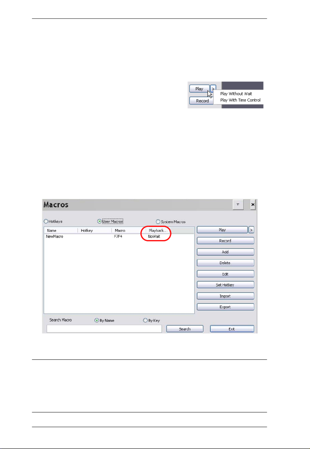
KL1508Ai / KL1516Ai User Manual
84
After creating your macros, you can run them in any of three ways:
1. By using the hotkey (if one was assigned).
2. By opening the Macro List on the Control Panel and clicking the one you
want (see page 78).
3. By opening this (Macros) dialog box and
clicking Play.
If you run the macro from this dialog box, you
have the option of specifying how the macro runs.
If you choose Play Without Wait, the macro runs the keypresses one after
another with no time delay between them.
If you choose Play With Time Control, the macro waits for the amount of
time between key presses that you took when you created it. Click on the
arrow next to Play to make your choice.
If you click Play without opening the list, the macro runs with the default
choice (NoWait or TimeCtrl), which is shown in the Playback column.
You can change the default choice by clicking on the current choice
(NoWait in the screenshot above), and selecting the alternate choice.
Note: 1. Information about the Search function is given on page 85.
2. User Macros are stored on the Local Client computer of each user.
Therefore, there is no limitation on the of number of macros, the size
of the macro names, or makeup of the hotkey combinations that
invoke them

Chapter 8. The User Interface
85
Search
Search, at the bottom of the dialog box, lets you filter the list of macros that
appear in the large upper panel for you to play or edit. Click a radio button to
choose whether you want to search by name or by key; key in a string for the
search; then click Search. All instances that match your search string appear in
the upper panel.
System Macros
System Macros are used to create exit macros for when you close a session. For
example, as an added measure of security, you could create a macro that sends
the Winkey-L combination which would cause the remote server’s log in page
to come up the next time the device was accessed. To create the macro, do the
following:
1. Select System Macros, then click Add.
2. In the dialog box that comes up, replace the “New Macro” text with a
name of your choice for the macro:
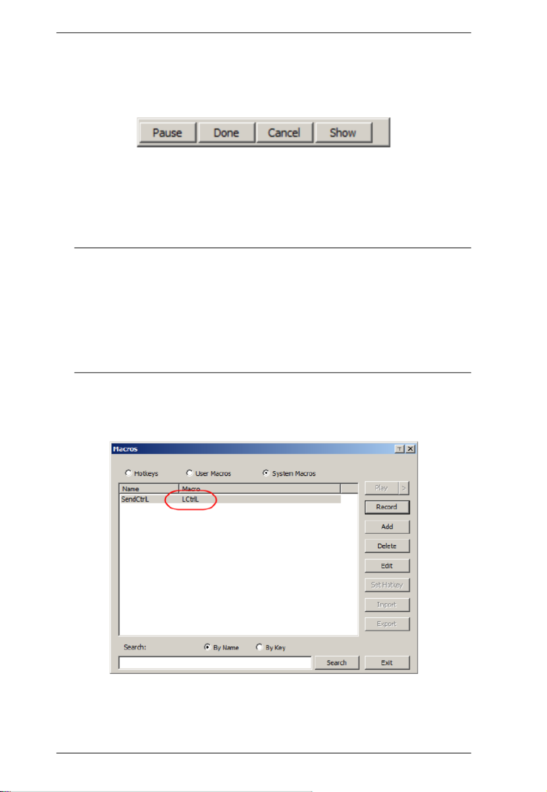
KL1508Ai / KL1516Ai User Manual
86
3. Click Record.
The dialog box disappears, and a small panel appears at the top left of the
screen:
4. Press the keys for the macro.
To pause macro recording, click Pause. To resume, click Pause again.
Clicking Show brings up a dialog box that lists each keystroke that you
make, together with the amount of time each one takes.
Note: 1. When recording the macro the focus must be on the remote
screen. It cannot be in the macro dialog box.
2. Case is not considered – typing A or a has the same effect. Only
the default keyboard characters may be used. Alternate characters
cannot be used. For example, if the keyboard is Traditional
Chinese and default character is A the alternate Chinese character
obtained via keyboard switching is not recorded.
5. If you haven’t brought up the Show dialog, click Done when you have
finished recording your macro. You return to the Macros dialog box with
your system macro key presses displayed in the Macro column:

Chapter 8. The User Interface
87
6. If you want to change any of the keystrokes, select the macro and click
Edit. This brings up a dialog box similar to the one for Show. You can
change the content of your keystrokes, change their order, etc.
7. Repeat the procedure for any other macros you wish to create.
Once the system macros have been created, they are available for use on a
port-by-port basis. They get selected on a port’s Port Configuration → Port
Properties page (see Port Configuration, page 142 for details).
Note: 1. Information about the Search function is given on page 85.
2. You can choose only one system macro per port.
3. Systems macros are stored on the switch, therefore macro names may
not exceed 64 Bytes; hotkey combinations may not exceed 256 Bytes.
(Each key usually takes 3–5 Bytes.)

Chapter 8. The User Interface
89
RGB Drag the slider bars to adjust the RGB (Red, Green, Blue) values.
When an RGB value is increased, the RGB component of the image
is correspondingly increased.
If you enable Set to Grayscale, the remote video display is changed
to grayscale.
Gamma This section allows you to adjust the video display's gamma level.
This function is discussed in detail in the next section, Gamma
Adjustment.
Network Type Select the type of internet connection that the local client computer
uses. The switch will use that selection to automatically adjust the
Video Quality and Detect Tolerance settings to optimize the quality of
the video display.
Since network conditions vary, if none of the pre-set choices seem to
work well, you can select Customize and use the Video Quality and
Detect Tolerance slider bars to adjust the settings to suit your
conditions.
Video Quality Drag the slider bar to adjust the overall Video Quality. The larger the
value, the clearer the picture and the more video data goes through
the network. Depending on the network bandwidth, a high value may
adversely effect response time.
Enable Refresh The KL1508Ai / KL1516Ai can redraw the screen every 1 to 99
seconds, eliminating unwanted artifacts from the screen. Select
Enable Refresh and enter a number from 1 through 99. The
KL1508Ai / KL1516Ai will redraw the screen at the interval you
specify. This feature is disabled by default. Click to put a check mark
in the box next to Enable Refresh to enable this feature.
Note: 1. The switch starts counting the time interval when mouse
movement stops.
2. Enabling this feature increases the volume of video data
transmitted over the network. The lower the number
specified, the more often the video data is transmitted.
Setting too low a value may adversely affect overall
operating responsiveness.
Transparency Adjusts the transparency of the toolbar that comes up when the GUI
hotkey ([Scroll Lock][Scroll Lock], for example), is invoked. Slide the
bar until the display in the example window is to your liking.
Color Depth
Control
This setting determines the richness of the video display by adjusting
the amount of color information.
Detect
Tolerance
This setting also relates to video quality. It governs detecting or
ignoring pixel changes. A high setting can result in a lower quality
display due to less data transfer. A lower setting will result in better
video quality, but setting the threshold too low may allow too much
data to be transferred, negatively impacting network performance.
Options Usage

KL1508Ai / KL1516Ai User Manual
90
Gamma Adjustment
If it is necessary to correct the gamma level for the remote video display, use
the Gamma function of the Video Adjustment dialog box.
Under Basic configuration, there are ten preset and four user-defined levels
to choose from. Drop down the list box and choose the most suitable one.
For greater control, clicking the Advanced button brings up the following
dialog box:
Click and drag the diagonal line at as many points as you wish to achieve
the display output you desire.
Click Save As to save up to four user-defined configurations derived from
this method. Saved configurations can be recalled from the list box at a
future time.
Click Reset to abandon any changes and return the gamma line to its
original diagonal position.
Click OK to save your changes and close the dialog box.
Click Cancel to abandon your changes and close the dialog box.
Note: For best results, change the gamma while viewing a remote server.
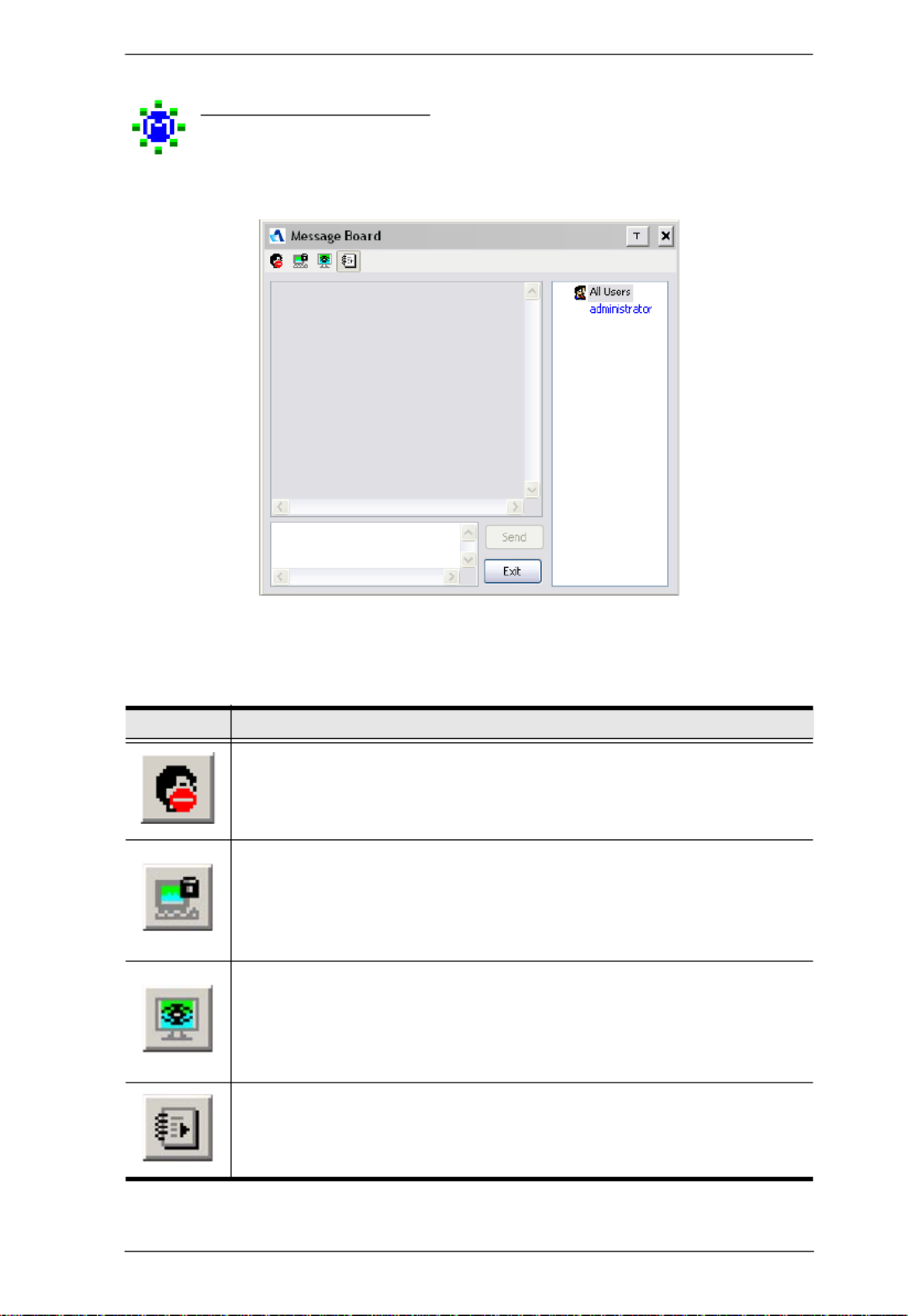
Chapter 8. The User Interface
91
The Message Board
The KL1508Ai / KL1516Ai supports multiple user logins, which may
cause access conflicts. To alleviate the problem, a message board has
been provided, which allows users to communicate with each other:
Button Bar
The buttons on the Button Bar are toggles. Their actions are described in the
table below:
Button Action
Enable/Disable Chat. When disabled, messages posted to the board
are not displayed. The button is shadowed when Chat is disabled. The
icon displays next to the user's name in the User List panel when the user
has disabled Chat.
Occupy/Release Keyboard/Video/Mouse. When you Occupy the KVM,
other users cannot see the video, and cannot input keyboard or mouse
data. The button is shadowed when the KVM is occupied. The icon
displays next to the user's name in the User List panel when the user has
occupied the KVM.
Occupy/Release Keyboard/Mouse. When you Occupy the KM, other
users can see the video, but cannot input keyboard or mouse data. The
button is shadowed when the KM is occupied. The icon displays next to
the user's name in the User List panel when the user has occupied the
KM.
Show/Hide User List. When you Hide the User List, the User List panel
closes. The button is shadowed when the User List is open.

Chapter 8. The User Interface
93
Zoom
The Zoom icon controls the zoom factor for the remote view window.
Settings are as follows:
Setting Description
100% Sizes and displays the remote view window at 100%.
75% Sizes and displays the remote view window at 75%.
50% Sizes and displays the remote view window at 50%.
25% Sizes and displays the remote view window at 25%.
1:1 Sizes and displays the remote view window at 100%. The difference
between this setting and the 100% setting is that when the remote
view window is resized its contents don’t resize – they remain at the
size they were. To see any objects that are outside of the viewing
area move the mouse to the window edge, to have the screen scroll.
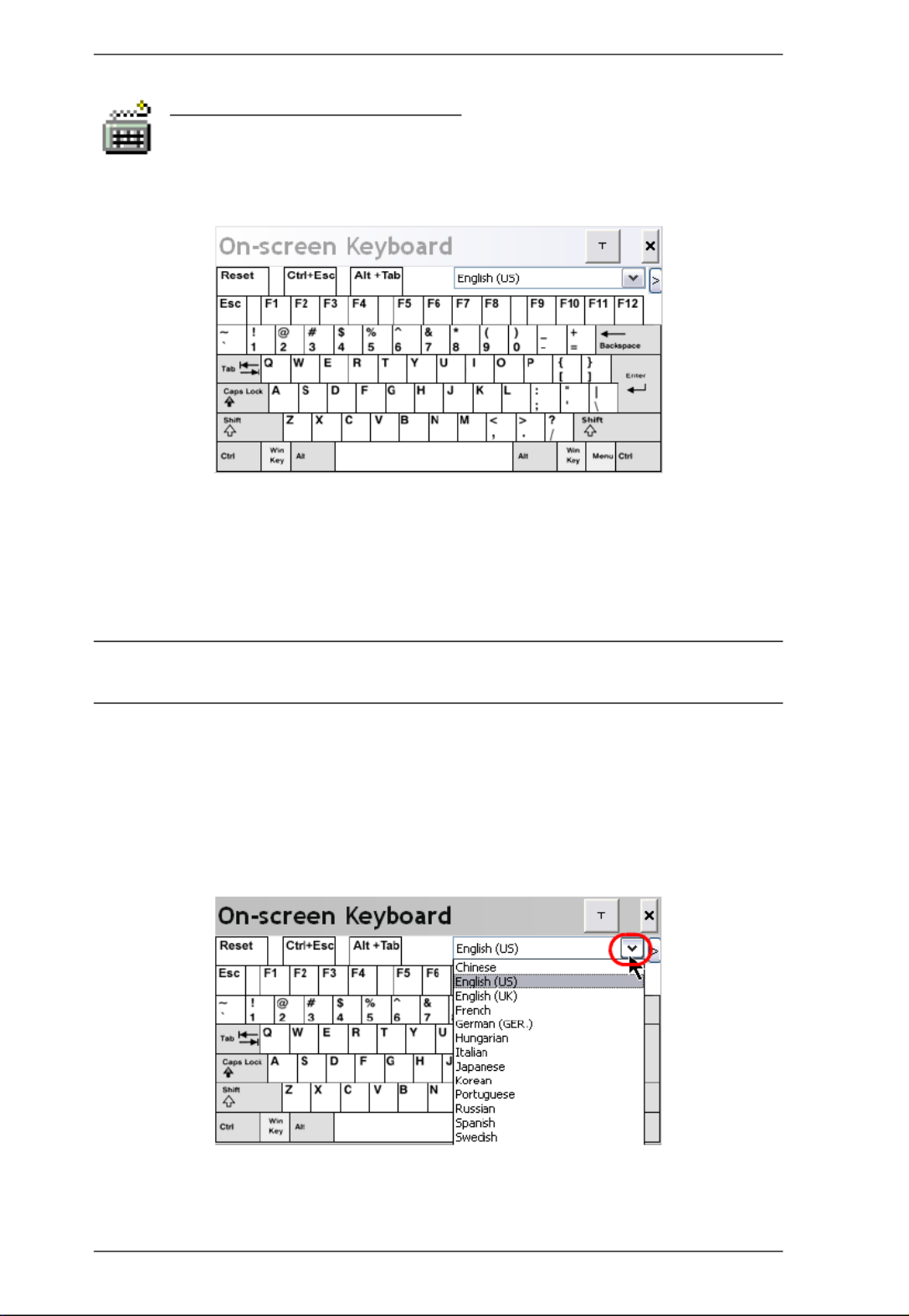
KL1508Ai / KL1516Ai User Manual
94
The On-Screen Keyboard
The KL1508Ai / KL1516Ai supports an on-screen keyboard,
available in multiple languages, with all the standard keys for each
supported language. Click this icon to pop up the on-screen keyboard:
One of the major advantages of the on-screen keyboard is that if the keyboard
languages of the remote and local systems aren’t the same, you don’t have to
change the configuration settings for either system. Just bring up the on-screen
keyboard; select the language used by the server you are accessing; and use the
on-screen keyboard to communicate with it.
Note: You must use your mouse to click on the keys. You cannot use your
actual keyboard.
Changing Languages
To change languages, do the following:
1. Click the down arrow next to the currently selected language, to drop
down the language list.
2. Select the new language from the list.
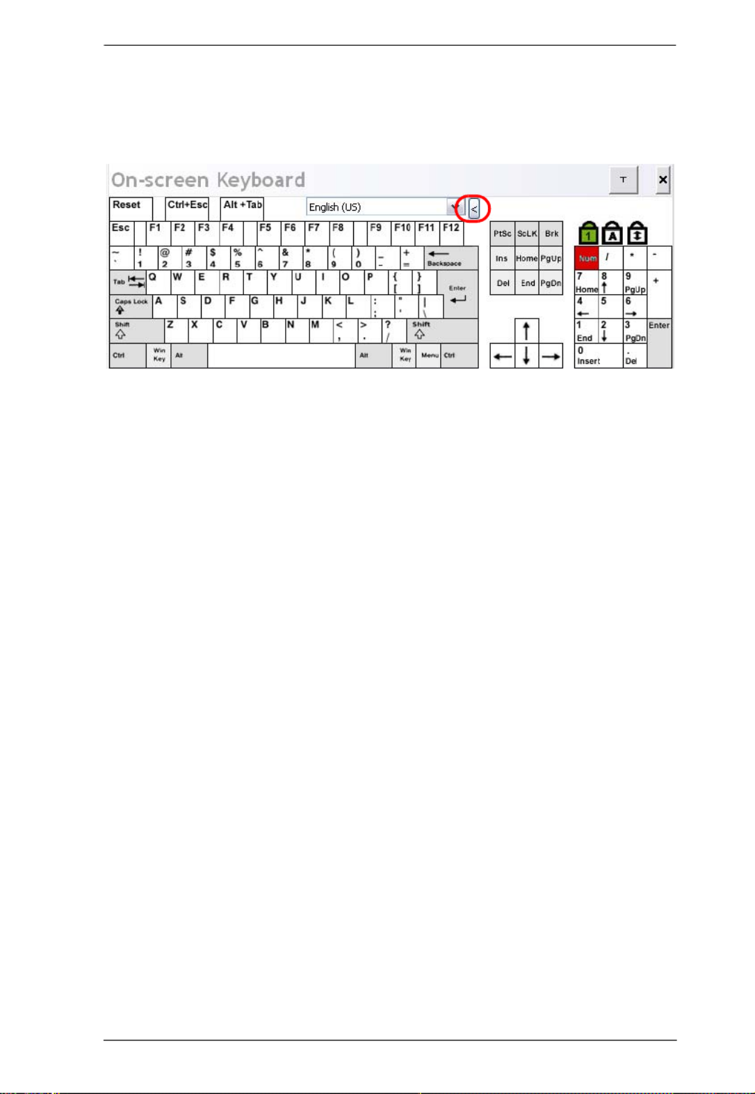
Chapter 8. The User Interface
95
Expanded Keyboard
To display/hide the expanded keyboard keys, click the arrow to the right of the
language list arrow.

KL1508Ai / KL1516Ai User Manual
96
Mouse Pointer Type
The KL1508Ai / KL1516Ai offer a number of mouse pointer options
when working in the remote display. Click this icon to select from the
available choices:
Note: 1. Before accessing a port, only Dual and Crosshairs are available for
the Windows Viewers. Once the port is accessed, all four pointers are
available.
2. The Dot pointer is not available with the Java Applet Viewer or the
Java Client AP.
3. Selecting the Dot pointer has the same effect as the Toggle mouse
display hotkey function (see Toggle Mouse Display, page 80 for
details).
4. The icon on the Control Panel changes to match your choice.
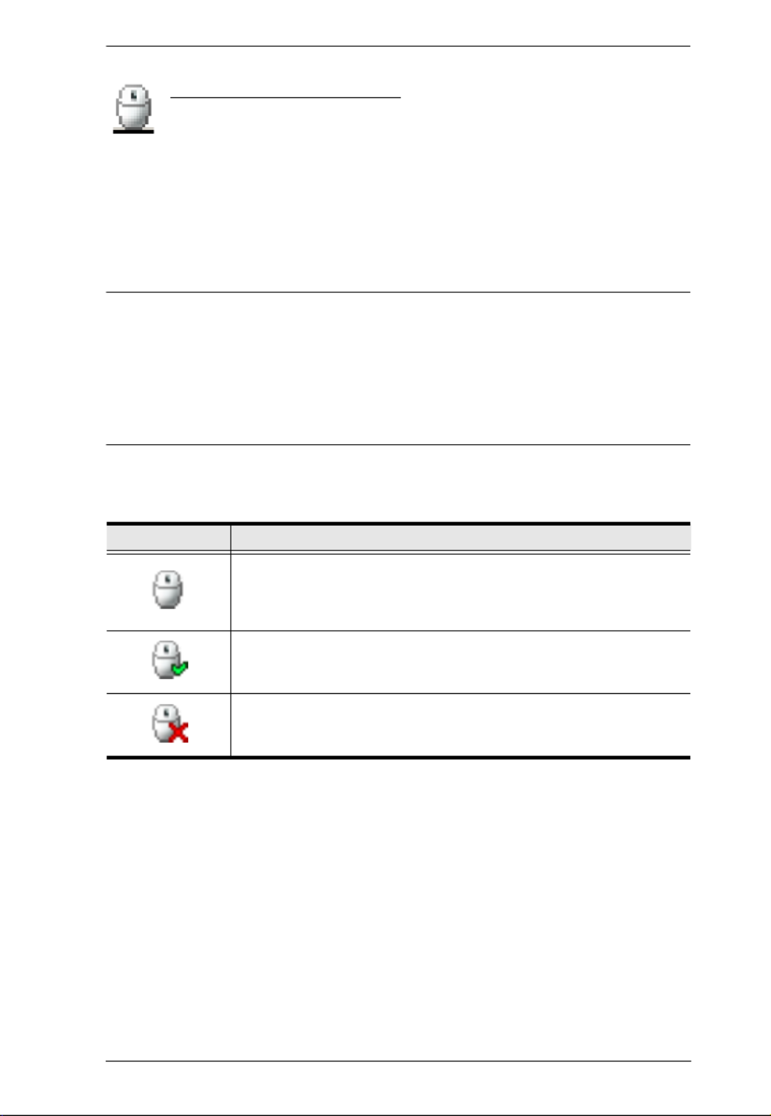
Chapter 8. The User Interface
97
Mouse DynaSync Mode
Synchronization of the local and remote mouse pointers is
accomplished either automatically or manually.
Automatic Mouse Synchronization (DynaSync)
Mouse DynaSync provides automatic locked-in synching of the remote and
local mouse pointers – eliminating the need to constantly resync the two
movements.
Note: This feature is only available for Windows and Mac systems (G4 and
higher) whose adapter attribute OS setting is configured for Win or
Mac, which are connected to the switch with one of the following
Adapter Cables: KA7166, KA7168, KA7169, KA7170 or KA9170.
All other configurations must use manual mouse synchronization
(described in the next section).
The icon on the Control Panel indicates the synchronization mode status as
follows:
When Mouse DynaSync is available, clicking the icon toggles its status
between enabled and /disabled. If you choose to disable Mouse DynaSync
mode, you must use the manual synching procedures described under Manual
Mouse Synchronization, page 98.
Icon Function
This icon displays in gray to indicate that Mouse DynaSync is not
available – you must use manual synching procedures. This is the
default setting for all KVM Adapters other than the KA7166,
KA7168, KA7169, KA7170 and KA9170.
The green check mark on this icon indicates that Mouse DynaSync
is available and is enabled. This is the default setting when Mouse
DynaSync is available. (See the Note, above.)
The red X on this icon indicates that Mouse DynaSync is available
but is not enabled.
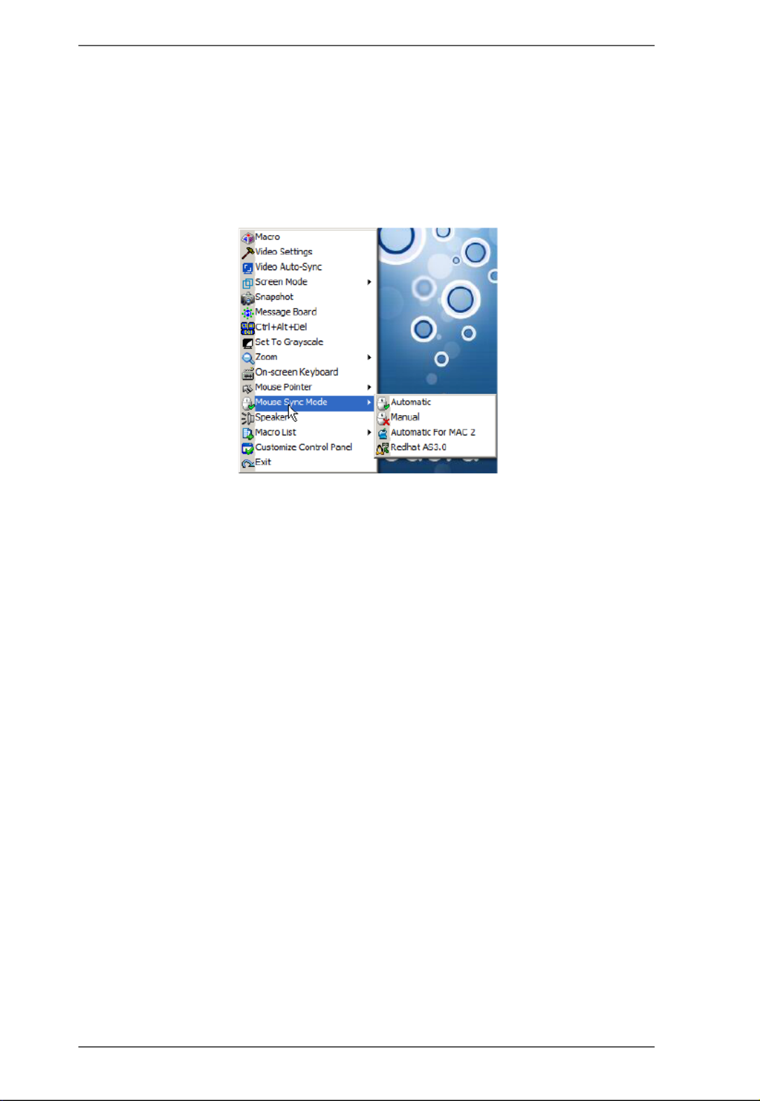
KL1508Ai / KL1516Ai User Manual
98
Mac and Linux Considerations
For Mac OS versions 10.4.11 and higher, there is a second DynaSync
setting to choose from. If the default Mouse DynaSync result is not
satisfactory, try the Mac 2 setting. To select Mac 2, right click in the text
area of the Control Panel and select Mouse Sync Mode → Automatic for
Mac 2:
Linux doesn’t support DynaSync Mode, but there is a setting on the Mouse
Sync Mode menu for Redhat AS3.0 systems. If you are using a USB
Adapter Cable (see the Note on the previous page), with an AS3.0 system
and the default mouse synchronization is not satisfactory, you can try the
Redhat AS3.0 setting. In either case, you must perform the manual mouse
synchronization procedures described in the next section.
Manual Mouse Synchronization
If the local mouse pointer goes out of sync with the remote system's mouse
pointer there are a number of methods to bring them back into sync:
1. Perform a video and mouse auto sync by clicking the Video Settings icon
on the Control Panel (see page 88).
2. Perform an Auto Sync with the Video Adjustment function (see Video
Settings, page 88, for details).
3. Invoke the Adjust Mouse function with the Adjust Mouse hotkeys (see
Adjust Mouse, page 80, for details).
4. Move the pointer into all 4 corners of the screen (in any order).
5. Drag the Control Panel to a different position on the screen.
6. Set the mouse speed and acceleration for each problematic server attached
to the switch. See Additional Mouse Synchronization Procedures,
page 208, for instructions.

Chapter 8. The User Interface
99
Control Panel Configuration
Clicking the Control Panel icon brings up a dialog box that allows you to
configure the items that appear on the Control Panel, as well as its graphical
settings:
The organization of the dialog box is described in the table, below:
Item Description
Customize
Control Panel
Allows you to select which icons display in the Control Panel. Check
the ones you want to see, uncheck the ones you don’t want.
Control Panel
Style Enabling Transparent makes the Control Panel semi-transparent,
so that you can see through it to the display underneath.
Enabling Icon causes the Control Panel to display as an icon until
you mouse over it, when the full panel then comes up.

KL1508Ai / KL1516Ai User Manual
100
Screen Options If Full Screen Mode is enabled, the remote display fills the entire
screen.
If Full Screen Mode is not enabled, the remote display appears as
a window on the local desktop. If the remote screen is larger than
what is able to fit in the window, move the mouse pointer to the
screen border that is closest to the area you want to view and the
screen will scroll.
If is enabled, the remote screen is not resized.Keep Screen Size
If the remote resolution is smaller than that of the local monitor,
its display appears like a window centered on the screen.
If the remote resolution is larger than that of the local monitor,
its display is centered on the screen. To access the areas that
are off screen, move the mouse to the corner of the screen that
is closest to the area you want to view and the screen will
scroll.
If Keep Screen Size is not enabled, the remote screen is resized to
fit the local monitor's resolution.
User Info If User Info is enabled, the total number of users displays on the
bottom row center of the Control Panel.
Snapshot These settings let the user configure the KL1508Ai / KL1516Ai’s
screen capture parameters (see the description under Snapshot
WinClient Control Panel Functions, page 77):
Path lets you select a directory where the captured screens get
saved to. Click Browse; navigate to the directory of your choice;
then click OK. If you don’t specify a directory here, the snapshot is
saved to your desktop.
Click a radio button to choose whether you want the captured
screen to be saved as a BMP or a JPEG (JPG) file.
If you choose JPEG, you can select the quality of the captured file
with the slider bar. The higher the quality, the better looking the
image, but the larger the file size.
Item Description
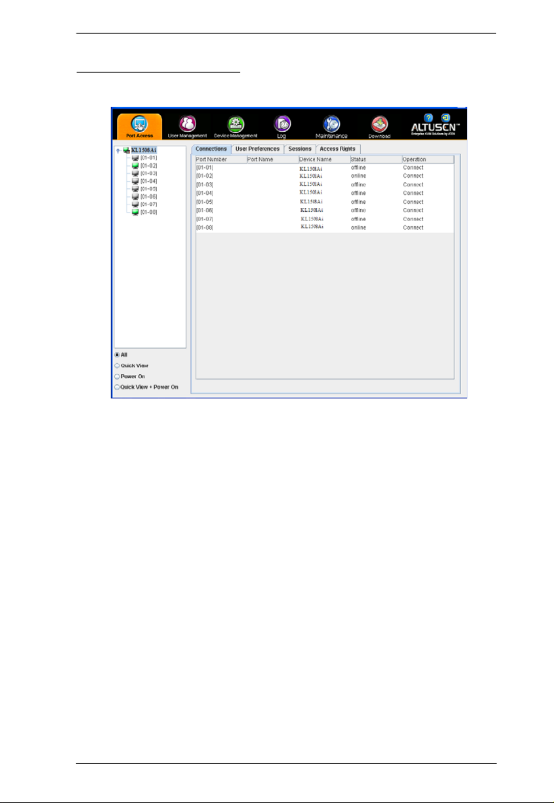
Chapter 8. The User Interface
101
The Java Control Panel
The Java Client AP Control Panel is similar to the one used by the WinClient:
The major differences between them are:
In the Macros dialog box, Toggle Mouse Display is not available.
The Dot mouse pointer type is not available.
In the Message Board, there is no Show/Hide button to show or hide the
user list. This function is achieved by clicking the arrows at the top of the
bar that separates the User List panel from the Main panel.
The Control Panel Lock LED icons are not in sync with your keyboard.
When you first connect, the LED display may not be accurate. To be sure,
click on the LED icons to set them.
In Control Panel Configuration, the BMP Snapshot format has been
replaced by PNG.

KL1508Ai / KL1516Ai User Manual
102
This Page Intentionally Left Blank
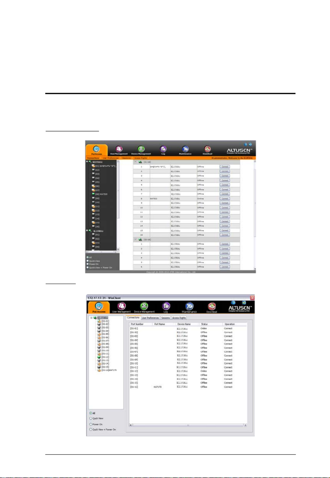
103
Chapter 9
Port Access
Overview
When you log in to the switch the Port Access page comes up with the
KL1508Ai / KL1516Ai’s KVM Connections page displayed.
Browser GUI
AP GUI

KL1508Ai / KL1516Ai User Manual
104
The Connections page is organized into several main areas. All the devices and
ports that a user is permitted to access are listed in the Sidebar at the left of the
page. After selecting a device or port in the Sidebar, clicking entries on the
menu bar (Browser GUI) or tab bar (AP GUI) opens information and
configuration pages related to the item selected in the Sidebar.

Chapter 9. Port Access
105
The Sidebar
All KVM switches are listed in a tree structure in the Sidebar at the left of the
screen:
The Sidebar Tree Structure
Users are only allowed to see the devices and ports that they have access
permission for.
Ports and child devices can be nested under their parent devices.
Click the + in front of a device to expand the tree and see the ports/outlets
nested underneath it. Click the - to collapse the tree and hide the nested
ports/outlets.
A port’s ID number is displayed in brackets next to its icon.
Switches and ports that are on line have their monitor screen icons in
Green; the monitor screens are Gray for devices and ports that are offline.
Outlets that are On have their icons in Amber; the icons are Gray for
outlets that are Off.
To access and operate a port, double click its icon. Port operation details
are discussed in Chapter 16, Port Operation.
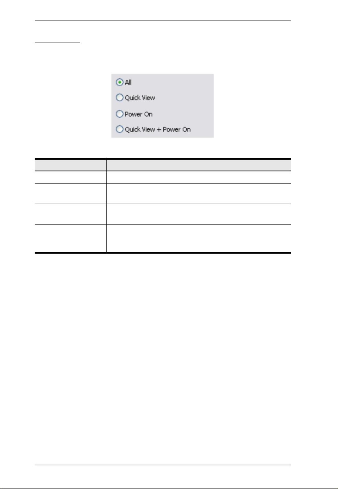
KL1508Ai / KL1516Ai User Manual
106
View Filter
At the bottom of the sidebar are the viewing filter options which allow you to
control the number and type of ports that display in the Sidebar:
The meanings of the choices are explained in the following table:
Choices Explanation
ALL Lists all of the ports on the installation.
QUICK VIEW Lists only the ports that have been selected as Quick View
Ports (see Set Quick View Ports, page 146).
POWER ON Lists only the ports that have attached computers Powered
On.
QUICK VIEW +
POWER ON
Lists only the ports that have been selected as Quick View
Ports (see Set Quick View Ports, page 146), and that have
their attached computers Powered On.

KL1508Ai / KL1516Ai User Manual
136
Login String
The Login String entry field lets the administrator specify a login string (in
addition to the IP address) that users must add to the IP address when they
access the KL1508Ai / KL1516Ai with a browser.
For example, if 192.168.0.126 were the IP address, and abcdefg were the login
string, then the user would have to key in:
192.168.0.126/abcdefg
Note: 1. Users must place a forward slash between the IP address and the
string.
2. If no login string is specified here, anyone will be able to access the
KL1508Ai / KL1516Ai login page using the IP address alone. This
makes your installation less secure.
The following characters are allowed in the string:
0–9 a–z A–Z ~ ! @ $ & * ( ) _ - = + [ ] , . |
The following characters are not allowed:
% ^ ” : / ? # \ ‘ { } ; ’ < > [Space]
Compound characters (É Ç ñ ... etc.)
For security purposes, we recommend that you change this string occasionally.

Chapter 11. Device Management
139
To add a MAC filter, do the following:
1. Click Add. A script prompt dialog box.
2. Specify the MAC address in the dialog box, then click OK.
3. Repeat these steps for any additional MAC addresses you want to filter.
IP Filter / MAC Filter Conflict
If there is a conflict between an IP filter and a MAC filter – in other words,
if a computer’s address is allowed by one filter but blocked by the other –
then the blocking filter takes precedence (the computer’s access is
blocked).
Modifying Filters
To modify a filter, select it in the IP Filter or MAC Filter list boxes and
click Modify. The Modify dialog box is similar to the Add dialog box.
When it comes up, simply delete the old address(es) and replace it with the
new one(s).
Deleting Filters
To delete a filter, select it in the IP Filter or MAC Filter list box and click
Delete.

KL1508Ai / KL1516Ai User Manual
140
Encryption
These flexible encryption alternatives for keyboard/mouse and video let you
choose any combination of DES; 3DES; AES; RC4; or a Random cycle of any
or all of them.
Enabling encryption affects system performance – no encryption offers the
best performance; the greater the encryption the greater the adverse effect. If
you enable encryption, ations are as follows:the performance consider
RC4 offers the least impact on performance; DES is next; then 3DES or
AES
The RC4 + DES combination offers the least impact of any combination
Working Mode
An explanation of the Working Mode items is given in the table, below:
Item Explanation
Enable ICMP If ICMP is enabled, the KL1508Ai / KL1516Ai can be pinged. If it is
not enabled, the device cannot be pinged. The default is Enabled.
Enable Multiuser
Operation
Enabling Multiuser operation permits up to 32 users to log in at the
same time to share the remote bus. If not enabled, only one user
can log in at a time. The default is Enabled.
Enable Browser Enabling Browser means browser access is permitted. If this is
disabled, users must access the switch with an HTTP URL.

Chapter 11. Device Management
141
Private Certificate
When logging in over a secure (SSL) connection, a signed certificate is used to
verify that the user is logging in to the intended site. For enhanced security, the
Private Certificate section allows you to use your own private encryption key
and signed certificate, rather than the default ATEN certificate.
There are two methods for establishing your private certificate: generating a
self-signed certificate; and importing a third-party certificate authority (CA)
signed certificate.
Generating a Self-Signed Certificate
If you wish to create your own self-signed certificate, a free utility –
openssl.exe – is available for download over the web. See Self-Signed
Private Certificates, page 200 for details about using OpenSSL to generate
your own private key and SSL certificate.
Obtaining a CA Signed SSL Server Certificate
For the greatest security, we recommend using a third party certificate
authority (CA) signed certificate. To obtain a third party signed certificate,
go to a CA (Certificate Authority) website to apply for an SSL certificate.
After the CA sends you the certificate and private encryption key, save
them to a convenient location on your computer.
Importing the Private Certificate
To import the private certificate, do the following:
1. Click Browse to the right of Private Key; browse to where your private
encryption key file is located; and select it.
2. Click Browse to the right of Certificate; browse to where your
certificate file is located; and select it.
3. Click Upload to complete the procedure.
Note: 1. Clicking Restore Default returns the device to using the default
ATEN certificate.
2. Both the private encryption key and the signed certificate must be
imported at the same time.

Chapter 11. Device Management
143
Exit Macro The Exit Macro panel contains a dropdown list box of user
created System macros. You can select a macro from the list
that will execute when exiting the remote server. See System
Macros, page 85 for details on creating exit macros.
Field Explanation
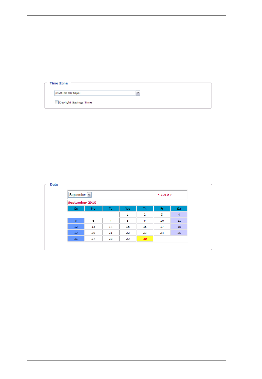
KL1508Ai / KL1516Ai User Manual
144
Date/Time
The Date/Time dialog page sets the KL1508Ai / KL1516Ai time parameters.
Set the parameters according to the information below.
Time Zone
To establish the time zone that the KL1508Ai / KL1516Ai is located in,
drop down the Time Zone list and choose the city that most closely
corresponds to where it is at.
If your country or region employs Daylight Saving Time (Summer Time),
check the corresponding checkbox.
Date
Select the month from the dropdown listbox.
Click < > or to move backward or forward by one year increments.
In the calendar, click on the day.
To set the time, use the 24 hour HH:MM:SS format.
Click Set to save your settings.
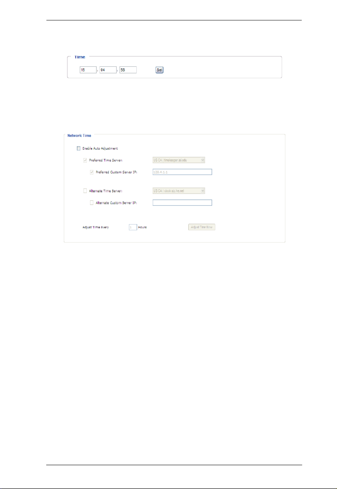
Chapter 11. Device Management
145
Time
To manually set the time, enter the values in the boxes and click Set.
Network Time
To have the time automatically synchronized to a network time server, do the
following:
1. Check the Enable auto adjustment checkbox.
2. Drop down the time server list to select your preferred time server
– or –
Check the Preferred custom server IP checkbox, and key in either the IPv4
address, IPv6 address, or domain name of the time server of your choice.
3. If you want to configure an alternate time server, check the Alternate time
server checkbox, and repeat step 2 for the alternate time server entries.
4. Key in your choice for the number of days between synchronization
procedures.
5. If you want to synchronize immediately, click Adjust Time Now.

147
Chapter 12
Log
Overview
The KL1508Ai / KL1516Ai logs all the events that take place on it. To view
the contents of the log, click the Log tab. The device’s Log Information page,
similar to the one below, appears:
Browser GUI
AP GUI

KL1508Ai / KL1516Ai User Manual
148
Log Information
The Log page displays events that take place on the KL1508Ai / KL1516Ai,
and provides a breakdown of the time, the user, and a description of each one.
You can change the sort order of the display by clicking on the column
headings.
The log file tracks a maximum of 512 events. When the limit is reached, the
oldest events get discarded as new events come in.
Product specificaties
| Merk: | ATen |
| Categorie: | Schakelaar |
| Model: | KL1508AIN |
| Kleur van het product: | Zwart |
| Ingebouwd display: | Ja |
| Gewicht: | 15390 g |
| Breedte: | 188.9 mm |
| Diepte: | 276 mm |
| Hoogte: | 44 mm |
| Materiaal behuizing: | Metaal |
| Stroombron: | AC |
| LED-indicatoren: | Ja |
| Stroom: | 1 A |
| Beeldscherm: | LCD |
| Beeldschermdiagonaal: | 19 " |
| USB-connectortype: | USB Type-A |
| Ethernet LAN: | Ja |
| Maximum resolutie: | 1600 x 1200 Pixels |
| Aantal Ethernet LAN (RJ-45)-poorten: | 1 |
| HD type: | SXGA |
| Duurzaamheidscertificaten: | RoHS |
| On Screen Display (OSD): | Ja |
| Ondersteunde beveiligingsalgoritmen: | 3DES, 128-bit SSL, 256-bit AES, DES, RSA |
| Ondersteunt Windows: | Ja |
| Aantal gebruikers: | 64 gebruiker(s) |
| Temperatuur bij opslag: | -20 - 60 °C |
| Sneltoetsen: | Ja |
| Upgraden van firmware mogelijk: | Ja |
| Ondersteunt Mac-besturingssysteem: | Ja |
| Rack-montage: | Ja |
| Ondersteunt Linux: | Ja |
| Andere ondersteundende systemen: | Ja |
| Aansluiting video: | VGA |
| Rackcapaciteit: | 1U |
| AC-ingangsspanning: | 100-240 V |
| AC-ingangsfrequentie: | 50 - 60 Hz |
| Stroomverbruik (typisch): | 27.5 W |
| Bedrijfstemperatuur (T-T): | 0 - 40 °C |
| Relatieve vochtigheid in bedrijf (V-V): | 0 - 80 procent |
| Aansluiting toetsenbord: | USB, PS/2 |
| Aansluiting muis: | USB, PS/2 |
| Aantal computers: | 128 |
| drukknop: | Ja |
| Console-poorten: | PS/2, USB A, VGA (D-Sub) |
| Videobandbreedte: | 75 Hz |
| Doorgelust: | Ja |
| Scaninterval: | 1, 255 s |
| Aantal USB-poorten console: | 3 |
| DDC2B-ondersteuning: | Ja |
Heb je hulp nodig?
Als je hulp nodig hebt met ATen KL1508AIN stel dan hieronder een vraag en andere gebruikers zullen je antwoorden
Handleiding Schakelaar ATen

17 November 2024
9 Juli 2023
9 Juli 2023
9 Juli 2023
9 Juli 2023
9 Juli 2023
8 Juli 2023
8 Juli 2023
8 Juli 2023
8 Juli 2023
Handleiding Schakelaar
- Schakelaar Bosch
- Schakelaar Philips
- Schakelaar HP
- Schakelaar IKEA
- Schakelaar Panasonic
- Schakelaar Huawei
- Schakelaar Asus
- Schakelaar Honeywell
- Schakelaar Yamaha
- Schakelaar Abus
- Schakelaar Airlive
- Schakelaar Alcatel
- Schakelaar Alecto
- Schakelaar Alpine
- Schakelaar Ansmann
- Schakelaar Apc
- Schakelaar Audiovox
- Schakelaar B-tech
- Schakelaar Basetech
- Schakelaar Behringer
- Schakelaar Belkin
- Schakelaar Berker
- Schakelaar Boss
- Schakelaar Brennenstuhl
- Schakelaar Buffalo
- Schakelaar D-Link
- Schakelaar Digitus
- Schakelaar Eaton
- Schakelaar EBERLE
- Schakelaar Ebode
- Schakelaar Edimax
- Schakelaar Elektrobock
- Schakelaar Elro
- Schakelaar Emerson
- Schakelaar Eminent
- Schakelaar Engenius
- Schakelaar Extech
- Schakelaar Finder
- Schakelaar Flamingo
- Schakelaar GAO
- Schakelaar Generac
- Schakelaar Gira
- Schakelaar Goobay
- Schakelaar Grandstream
- Schakelaar Grasslin
- Schakelaar Hager
- Schakelaar Hama
- Schakelaar Hikvision
- Schakelaar Intermatic
- Schakelaar Inverto
- Schakelaar Kathrein
- Schakelaar KlikaanKlikuit
- Schakelaar Konig
- Schakelaar Kopp
- Schakelaar Lancom
- Schakelaar LevelOne
- Schakelaar Linksys
- Schakelaar Logilink
- Schakelaar Manhattan
- Schakelaar Marmitek
- Schakelaar Mercury
- Schakelaar Merlin Gerin
- Schakelaar Mikrotik
- Schakelaar Monacor
- Schakelaar Nedis
- Schakelaar Netgear
- Schakelaar Paladin
- Schakelaar PCE
- Schakelaar Perel
- Schakelaar Plantronics
- Schakelaar Powerfix
- Schakelaar Profile
- Schakelaar Provision ISR
- Schakelaar Pyle
- Schakelaar QNAP
- Schakelaar Renkforce
- Schakelaar Rex
- Schakelaar Robbe
- Schakelaar Schneider
- Schakelaar SEC24
- Schakelaar Shimano
- Schakelaar Silvercrest
- Schakelaar Smartwares
- Schakelaar Speaka
- Schakelaar Suevia
- Schakelaar Sygonix
- Schakelaar Sylvania
- Schakelaar Tenda
- Schakelaar Tesla
- Schakelaar Theben
- Schakelaar Tiptel
- Schakelaar Toolcraft
- Schakelaar Tork
- Schakelaar TP Link
- Schakelaar Trendnet
- Schakelaar Triax
- Schakelaar Trotec
- Schakelaar Unify
- Schakelaar UPM
- Schakelaar Velleman
- Schakelaar Vivanco
- Schakelaar WHALE
- Schakelaar Worx
- Schakelaar ZyXEL
- Schakelaar Jabra
- Schakelaar Jung
- Schakelaar Omnitronic
- Schakelaar One For All
- Schakelaar Clas Ohlson
- Schakelaar CSL
- Schakelaar Monoprice
- Schakelaar Steren
- Schakelaar DoorBird
- Schakelaar Ubiquiti Networks
- Schakelaar EMOS
- Schakelaar Kaiser
- Schakelaar Cotech
- Schakelaar Atlona
- Schakelaar Hamlet
- Schakelaar Comet
- Schakelaar Vivolink
- Schakelaar Techly
- Schakelaar SIIG
- Schakelaar Merten
- Schakelaar Tripp Lite
- Schakelaar Chacon
- Schakelaar Nexa
- Schakelaar Dormakaba
- Schakelaar SPC
- Schakelaar Cisco
- Schakelaar Victron Energy
- Schakelaar Delta Dore
- Schakelaar Fantini Cosmi
- Schakelaar Vemer
- Schakelaar Matrox
- Schakelaar Gefen
- Schakelaar Ei Electronics
- Schakelaar Fibaro
- Schakelaar GEV
- Schakelaar Juniper
- Schakelaar Planet
- Schakelaar Chamberlain
- Schakelaar Intellinet
- Schakelaar CyberPower
- Schakelaar SunBriteTV
- Schakelaar Lindy
- Schakelaar IOGEAR
- Schakelaar Black Box
- Schakelaar IFM
- Schakelaar DataVideo
- Schakelaar Wago
- Schakelaar Sonance
- Schakelaar Totolink
- Schakelaar Dahua Technology
- Schakelaar AV:link
- Schakelaar PreSonus
- Schakelaar Mercusys
- Schakelaar Elation
- Schakelaar EVE
- Schakelaar Audac
- Schakelaar Vacmaster
- Schakelaar RGBlink
- Schakelaar PAC
- Schakelaar Wentronic
- Schakelaar Adder
- Schakelaar Homematic IP
- Schakelaar Extron
- Schakelaar AMX
- Schakelaar OSD Audio
- Schakelaar Equip
- Schakelaar Crestron
- Schakelaar ORNO
- Schakelaar Aeon Labs
- Schakelaar Electro Harmonix
- Schakelaar StarTech.com
- Schakelaar PureLink
- Schakelaar Advantech
- Schakelaar Smart-AVI
- Schakelaar Brilliant
- Schakelaar Kramer
- Schakelaar Micro Connect
- Schakelaar KanexPro
- Schakelaar Intelix
- Schakelaar Blustream
- Schakelaar Avocent
- Schakelaar Shelly
- Schakelaar ICasa
- Schakelaar Vimar
- Schakelaar Kemo
- Schakelaar H-Tronic
- Schakelaar Legrand
- Schakelaar Kraus & Naimer
- Schakelaar Noble
- Schakelaar Intertechno
- Schakelaar Ecler
- Schakelaar Rule
- Schakelaar CYP
- Schakelaar Phoenix Contact
- Schakelaar Seuthe
- Schakelaar Maclean Energy
- Schakelaar SmartAVI
- Schakelaar Leviton
- Schakelaar DEHN
- Schakelaar Cudy
- Schakelaar Heitronic
- Schakelaar Noark
- Schakelaar Cooking Performance Group
- Schakelaar Ernitec
- Schakelaar Adviti
- Schakelaar Flic
- Schakelaar HELGI
- Schakelaar IB Connect
- Schakelaar Liberty
- Schakelaar PureTools
- Schakelaar Alfatron
- Schakelaar Cambium Networks
- Schakelaar 2USB
- Schakelaar Roline
- Schakelaar KVM-TEC
- Schakelaar BZBGear
- Schakelaar STI
- Schakelaar Epiphan
- Schakelaar Ebara
- Schakelaar Mach Power
- Schakelaar Axing
- Schakelaar Raritan
- Schakelaar ConnectPro
- Schakelaar Atlantis Land
- Schakelaar Pizzato Elettrica
- Schakelaar Baco
- Schakelaar SEADA
- Schakelaar Doepke
- Schakelaar IPGARD
- Schakelaar Setti+
- Schakelaar INOGENI
- Schakelaar Luxul
Nieuwste handleidingen voor Schakelaar
8 April 2025
4 April 2025
4 April 2025
4 April 2025
4 April 2025
3 April 2025
3 April 2025
1 April 2025
1 April 2025
1 April 2025