Asus TW300-E5/PI4 Handleiding
Lees hieronder de 📖 handleiding in het Nederlandse voor Asus TW300-E5/PI4 (174 pagina's) in de categorie Server. Deze handleiding was nuttig voor 50 personen en werd door 2 gebruikers gemiddeld met 4.5 sterren beoordeeld
Pagina 1/174

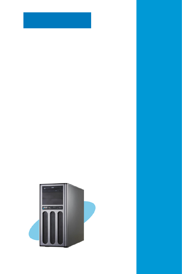
TW300-E5/PI4
Intel® LGA775 Core™ 2 Extreme /
Core™ 2 Quad / Core™ 2 Duo Series
Workstation
User’s Manaual

ii
Copyright © 2008 ASUSTeK COMPUTER INC. All Rights Reserved.
No part of this manual, including the products and software described in it, may be reproduced,
transmitted, transcribed, stored in a retrieval system, or translated into any language in any form or by any
means, except documentation kept by the purchaser for backup purposes, without the express written
permission of ASUSTeK COMPUTER INC. (“ASUS”).
ASUS provides this manual “as is” without warranty of any kind, either express or implied, including but not
limited to the implied warranties or conditions of merchantability or tness for a particular purpose. In no
event shall ASUS, its directors, ofcers, employees, or agents be liable for any indirect, special, incidental,
or consequential damages (including damages for loss of prots, loss of business, loss of use or data,
interruption of business and the like), even if ASUS has been advised of the possibility of such damages
arising from any defect or error in this manual or product.
Specications and information contained in this manual ae furnished for informational use only, and are
subject to change at any time without notice, and should not be construed as a commitment by ASUS.
ASUS assumes no responsibility or liability for any errors or inaccuracies that may appear in this manual,
including the products and software described in it.
Product warranty or service will not be extended if: (1) the product is repaired, modied or altered, unless
such repair, modication of alteration is authorized in writing by ASUS; or (2) the serial number of the
product is defaced or missing.
Products and corporate names appearing in this manual may or may not be registered trademarks or
copyrights of their respective companies, and are used only for identication or explanation and to the
owners’ benet, without intent to infringe.
E3822
First Edition
May 2008

iii
Contents
Contents ...................................................................................................... iii
Notices ....................................................................................................... viii
Safety information ...................................................................................... ix
About this guide .......................................................................................... x
Chapter 1: Product introduction
1.1 System package contents ........................................................... 1-2
1.2 Serial number label ...................................................................... 1-2
1.3 Systemspecications ................................................................. 1-3
1.4 Front panel features ..................................................................... 1-5
1.5 Rear panel features ...................................................................... 1-6
1.6 Internal features ........................................................................... 1-7
1.7 LED information ........................................................................... 1-8
1.7.1 Front panel LEDs ............................................................ 1-8
1.7.2 LAN (RJ-45) LEDs .......................................................... 1-8
Chapter 2: Hardware setup
2.1 Chassis cover ............................................................................... 2-2
2.1.1 Removing the left side cover ........................................... 2-2
2.1.2 Removing the right side cover 2- ........................................ 3
2.2 Motherboard overview ................................................................. 2-4
2.3 Central Processing Unit (CPU) ................................................... 2-5
2.3.1 Installing the CPU ........................................................... 2-5
2.3.2 Installing the CPU heatsink ............................................. 82-
2.4 System memory ......................................................................... 2-10
2.4.1 Overview ....................................................................... 2-10
2.4.2 Memory congurations ...................................................2-11
2.4.3 Installing a DIMM .......................................................... 2-12
2.4.4 Removing a DIMM ........................................................ 2-12
2.5 Installing hard disk drives ......................................................... 2-13
2.6 Installing 5.25-inch drives ......................................................... 2-15
2.6.1 Removing the front panel cover .................................... 2-15
2.6.2 Installing an additional optical drive .............................. 2-16
2.7 Expansion cards ........................................................................ 2-19
2.7.1 Installing expansion cards ............................................. 92-1
2.7.2 Conguring an expansion card ..................................... 2-20

iv
Contents
2.7.3 Interrupt assignments 2-2 ................................................... 1
2.8 Removing components ............................................................. 2-22
2.8.1 Removing the oppy disk drive ..................................... 2-22
2.8.2 Removing the system fan 2-2 ............................................. 3
2.8.3 Removing the SATA backplane ..................................... 2-24
2.9 Connecting cables ..................................................................... 2-26
Chapter 3: Motherboard info
3.1 Motherboard layouts .................................................................... 3-2
3.2 Jumpers ........................................................................................ 3-6
3.3 Connectors ................................................................................... 3-8
3.3.1 Rear panel connectors .................................................... 3-8
3.3.2 Internal connectors ........................................................3-11
Chapter 4: BIOS infomation
4.1 Managing and updating your BIOS ............................................ 4-2
4.1.1 ASUS Update utility 4-2 ........................................................
4.1.2 Creating a bootable oppy disk ....................................... 4-5
4.1.3 ASUS EZ Flash 2 utility ................................................... 4-6
4.1.4 AFUDOS utility ................................................................ 74-
4.1.5 ASUS CrashFree BIOS 3 utility 4- ...................................... 9
4.2 BIOS setup program .................................................................. 4-10
4.2.1 BIOS menu screen .........................................................4-11
4.2.2 Menu bar ........................................................................4-11
4.2.3 Navigation keys ..............................................................4-11
4.2.4 Menu items 4-12 ...................................................................
4.2.5 Sub-menu items ............................................................ 4-12
4.2.6 Conguration elds ....................................................... 4-12
4.2.7 Pop-up window 4-12 .............................................................
4.2.8 Scroll bar ....................................................................... 4-12
4.2.9 General help 4-12 .................................................................
4.3 Main menu .................................................................................. 4-13
4.3.1 System Time ................................................................. 34-1
4.3.2 System Date 4-1 ................................................................. 3
4.3.3 Legacy Diskette A ......................................................... 34-1
4.3.4 Language ...................................................................... 34-1

v
Contents
4.3.5 SATA 1~6 .........................................................................................4-14
4.3.6 SATA Conguration ....................................................... 4-15
4.3.7 AHCI Conguration ....................................................... 4-16
4.3.8 System Information ....................................................... 74-1
4.4 Ai Tweaker menu ........................................................................ 4-18
4.4.1 Ai Overclock Tuner ....................................................... 84-1
4.4.2 CPU Ratio Control 4-1 ....................................................... 9
4.4.3 FSB Strap to North Bridge ........................................... 94-1
4.4.4 DRAM Frequency 4-20 ........................................................
4.4.5 DRAM Command Rate ................................................ 4-20
4.4.6 DRAM CMD Skew on Channel A/B ............................. 4-20
4.4.7 DRAM CLK Skew on Channel A/B ............................... 4-20
4.4.8 DRAM Timing Control .................................................. 4-20
4.4.9 DRAM Static Read Control .......................................... 14-2
4.4.10 Ai Clock Twister 4-2............................................................ 1
4.4.11 Transaction Booster ..................................................... 4-22
4.4.12 CPU Voltage 4-22 ...............................................................
4.4.13 CPU PLL Voltage ......................................................... 4-22
4.4.14 FSB Termination Voltage 4-22..............................................
4.4.15 DRAM Voltage 4-22 .............................................................
4.4.16 North Bridge Voltage .................................................... 4-22
4.4.17 South Bridge Voltage ................................................... 34-2
4.4.18 Clock Over-Charging Voltage ...................................... 34-2
4.4.19 CPU Spread Spectrum 4-2 ................................................ 3
4.4.20 PCIE Spread Spectrum ................................................ 4-24
4.5 Advanced menu ......................................................................... 4-25
4.5.1 CPU Conguration ........................................................ 4-25
4.5.2 Chipset .......................................................................... 74-2
4.5.3 OnBoard Devices Conguration 4-2 ................................... 8
4.5.4 PCI PnP ........................................................................ 94-2
4.5.5 USB Conguration ........................................................ 4-30
4.6 Power menu ................................................................................ 4-31
4.6.1 Suspend Mode ............................................................. 14-3
4.6.2 Repost Video on S3 Resume ........................................ 14-3
4.6.3 ACPI 2.0 Support .......................................................... 14-3

vi
Contents
4.6.4 ACPI APIC Support ....................................................... 14-3
4.6.5 APM Conguration ........................................................ 4-32
4.6.6 Hardware Monitor 4-3 ......................................................... 3
4.7 Boot menu .................................................................................. 4-35
4.7.1 Boot Device Priority 4-35 ......................................................
4.7.2 Boot Settings Conguration .......................................... 4-36
4.7.3 Security ......................................................................... 74-3
4.8 Tools menu ................................................................................. 4-39
4.8.1 ASUS EZ Flash 2 .......................................................... 94-3
4.8.2 ASUS O.C. Prole ......................................................... 4-40
4.8.3 Ai Net 2 ......................................................................... 14-4
4.9 Exit menu .................................................................................... 4-42
Chapter5: RAIDconguration
5.1 RAIDcongurations .................................................................... 5-2
5.1.1 RAID denitions .............................................................. 5-2
5.1.2 Installing hard disk drives ................................................ 35-
5.1.3 Setting the RAID item in BIOS ........................................ 35-
5.2 Marvel®88SE6145RAIDBIOSCongurationUtility ................. 5-4
5.2.1 Creating a RAID set ........................................................ 5-5
5.2.2 Deleting an array ............................................................. 85-
5.3 Intel® Matrix Storage Manager Option ROM Utility ................. 5-10
5.3.1 Creating a RAID 0 set (Stripe) .......................................5-11
5.3.2 Creating a RAID 1 set (Mirror) ...................................... 35-1
5.3.3 Creating a RAID 10 set (Stripe + Mirror) ....................... 5-14
5.3.4 Creating a RAID 5 set (Parity) 5-15 ......................................
5.3.5 Deleting a RAID set 5-16 ......................................................
5.3.6 Resetting disks to Non-RAID ........................................ 75-1
5.3.7 Rebuilding the RAID 5-1 ..................................................... 7
5.3.8 Exiting the Intel® Matrix Storage Manager .................... 5-20
5.3.9 Setting the Boot array use MB BIOS Setup Utility ........ 5-20
5.3.10 Global Array Manager ................................................... 15-2
Chapter 6: Driver installation
6.1 RAID driver installation ............................................................... 6-2
6.1.1 Creating a RAID driver disk without entering the OS ...... 6-2

vii
6.1.2 Creating a RAID/SATA driver disk in Windows® .............. 6-2
6.1.3 Installing the RAID controller driver 6- ................................ 3
6.1.4 Installing an operating system 6-5 ........................................
6.2 Support DVD information ............................................................ 6-6
6.2.1 Running the support DVD ............................................... 6-6
6.2.2 Drivers menu ................................................................... 76-
6.2.3 Utilities menu 6- .................................................................. 8
6.2.4 Make Disk menu ........................................................... 6-10
6.2.5 Manual menu .................................................................6-11
6.2.6 ASUS Contact information .............................................6-11
6.2.7 Other information .......................................................... 6-12
6.3 Software information ................................................................. 6-14
6.3.1 ASUS MyLogo2™ ......................................................... 6-14
6.3.2 Audio congurations 6-16 .....................................................
6.3.3 ASUS PC Probe II ......................................................... 6-24
6.3.4 ASUS AI Suite ............................................................... 6-30
6.3.5 ASUS AI Gear 2 ............................................................ 6-32
6.3.6 ASUS AI Nap 6-3 ................................................................ 3
6.3.7 ASUS AI N.O.S. ............................................................ 6-34
6.3.8 ASUS Q-Fan 2 .............................................................. 6-35
6.3.9 ASUS AI Booster ........................................................... 6-36
Appendix: Reference information
A.1 Intel® EM64T ..................................................................................A-2
Using the Intel® EM64T feature ......................................................A-2
A.2 Enhanced Intel SpeedStep® Technology (EIST) ........................A-2
A.2.1 System requirements ......................................................A-2
A.2.2 Using the EIST ................................................................A-3
A.3 Intel® Hyper-Threading Technology ...........................................A-4
Using the Hyper-Threading Technology ........................................A-4
A.4 Simplexes ..................................................................................A-5
Contents

viii
Notices
Federal Communications Commission Statement
This device complies with Part 15 of the FCC Rules. Operation is subject to the
following two conditions:
•
This device may not cause harmful interference, and
•
This device must accept any interference received including interference that
may cause undesired operation.
This equipment has been tested and found to comply with the limits for a
Class B digital device, pursuant to Part 15 of the FCC Rules. These limits are
designed to provide reasonable protection against harmful interference in a
residential installation. This equipment generates, uses and can radiate radio
frequency energy and, if not installed and used in accordance with manufacturer’s
instructions, may cause harmful interference to radio communications. However,
there is no guarantee that interference will not occur in a particular installation. If
this equipment does cause harmful interference to radio or television reception,
which can be determined by turning the equipment off and on, the user is
encouraged to try to correct the interference by one or more of the following
measures:
•
Reorient or relocate the receiving antenna.
•
Increase the separation between the equipment and receiver.
•
Connect the equipment to an outlet on a circuit different from that to which the
receiver is connected.
•
Consult the dealer or an experienced radio/TV technician for help.
WARNING! The use of shielded cables for connection of the monitor to the
graphics card is required to assure compliance with FCC regulations. Changes
or modications to this unit not expressly approved by the party responsible for
compliance could void the user’s authority to operate this equipment.
Canadian Department of Communications Statement
This digital apparatus does not exceed the Class B limits for radio noise emissions
from digital apparatus set out in the Radio Interference Regulations of the
Canadian Department of Communications.
This class B digital apparatus complies with Canadian ICES-003.
This symbol of the crossed out wheeled bin indicates that the product (electrical,
electronic equipment and mercury-containing button cell battery) should not
be placed in municipal waste. Check local regulations for disposal of electronic
products.

ix
Safety information
Electrical Safety
• Before installing or removing signal cables, ensure that the power cables for
the system unit and all attached devices are unplugged.
• To prevent electrical shock hazard, disconnect the power cable from the
electrical outlet before relocating the system.
• When adding or removing any additional devices to or from the system, contact
a qualied service technician or your dealer. Ensure that the power cables for
the devices are unplugged before the signal cables are connected. If possible,
disconnect all power cables from the existing system before you service.
• If the power supply is broken, do not try to x it by yourself. Contact a qualied
service technician or your dealer.
Operation Safety
• Servicing of this product or units is to be performed by trained service
personnel only.
• Before operating the server, carefully read all the manuals included with the
server package.
• Before using the server, make sure all cables are correctly connected and the
power cables are not damaged. If any damage is detected, contact your dealer
as soon as possible.
• To avoid short circuits, keep paper clips, screws, and staples away from
connectors, slots, sockets and circuitry.
• Avoid dust, humidity, and temperature extremes. Place the server on a stable
surface.
This product is equipped with a three-wire power cable and plug for the user’s
safety. Use the power cable with a properly grounded electrical outlet to avoid
electrical shock.
Lithium-Ion Battery Warning
CAUTION! Danger of explosion if battery is incorrectly replaced.
Replace only with the same or equivalent type recommended by the
manufacturer. Dispose of used batteries according to the manufacturer’s
instructions.
CD-ROM Drive Safety Warning
CLASS 1 LASER PRODUCT
Heavy System
CAUTION! This server system is heavy. Ask for assistance when moving or
carrying the system.

x
About this guide
Audience
This user guide is intended for system integrators and experienced users with at
least basic knowledge of conguring a workstation.
Contents
This guide contains the following parts:
1. Chapter 1: Product Introduction
This chapter describes the general features of the workstation, including
sections on front panel and rear panel specications.
2. Chapter 2: Hardware setup
This chapter lists the hardware setup procedures that you have to perform
when installing or removing system components.
3. Chapter 3: Motherboard information
This chapter gives information about the motherboard that comes with the
workstation. This chapter includes the motherboard layout, jumper settings,
and connector locations.
4. Chapter 4: BIOS information
This chapter tells how to change system settings through the BIOS Setup
menus and describes the BIOS parameters.
5. Chapter5:RAIDconguration
This chapter provides information on how to congure your hard disk drives
as RAID sets.
6. Chapter 6: Driver installation
This chapter provides information on how to install the drivers for system
components. This chapter also describes the software applications that the
barebone workstation supports.
7. Appendix: Reference information
This section provides information about the CPU features and technologies
and a troubleshooting guide for solving common problems when using the
barebone workstation.

xi
Reference
Visit the ASUS websites worldwide that provide updated information for all ASUS
hardware and software products. Refer to the ASUS contact information for details.
WARNING: Information to prevent injury to yourself when trying to
complete a task.
CAUTION: Information to prevent damage to the components when trying
to complete a task.
IMPORTANT: Instructions that you MUST follow to complete a task.
NOTE: Tips and information to aid in completing a task.
Conventions
To make sure that you perform certain tasks properly, take note of the following
symbols used throughout this manual.

xii

1-
ASUS TW300-E5/PI4
This chapter describes the general
features of the workstation, including
sections on front panel and rear panel
specications.
Chapter 1
Product introduction

Chapter 1: Product introduction1-2
If any of the above items is damaged or missing, contact your retailer.
1.1 System package contents
Check your system package for the following items.
Model Name TW300-E5/PI4
Chassis ASUS T10 Pedestal Chassis
Motherboard ASUS P5E WS Professional
Component 1 x 450W Single Power Supply
1 x 95mm System Fan
5 x SATA Cables
1 x 7-in-1 Card Reader
4 x Internal HDD trays
1 x Front I/O Board
Accessories 1 x ASUS TW300-E5/PI4 User’s Guide
1 x TW300-E5/PI4 Support CD
1 x Bag of Screws
1 x AC Power Cable
1 x CPU Heatsink
Optional Items -
1.2 Serial number label
Before requesting support from the ASUS Technical Support team, you must
take note of the product’s serial number containing 12 characters such as
xxxxxxxxxxxx. See the gure below.
With the correct serial number of the product, ASUS Technical Support team
members can then offer a quicker and satisfying solution to your problems.
xxxxxxxxxxxx
TW300-E5/PI4

ASUS TW300-E5/PI4 1-3
1.3 Systemspecications
The ASUS TW300-E5/PI4 is a workstation featuring the ASUS P5E WS
Professional motherboard. The workstation supports Intel® LGA775
Core™ 2 Extreme / Core™ 2 Quad / Core™ 2 Duo processors with EM64T
technology, plus other latest technologies through the chipsets onboard.
(continued on the next page)
Model Name TW300-E5/PI4
Processor / System Bus
1 x Socket LGA775
Quad-core:
Intel® Core™ 2 Extreme QX9000 Series (45nm)
Intel® Core™ 2 Extreme QX6000 Series
Intel® Core™ 2 Quad Q9000 Series (45nm)
Intel® Core™ 2 Quad Q6000 Series
Dual-core:
Intel® Core™ 2 Duo E8000 Series (45nm)
Intel® Core™ 2 Duo E6000 Series
FSB 1333 / 1066 / 800 MHz with EM64T
Core Logic
Intel® X38 MCH
Intel® ICH9R
PCI-X NEC upd720404
ASUS Features Q Fan √
Memory
Total Slots 4 (Dual-Channel)
Capacity Maximum up to 8GB
Memory Type DDR2 800 / 667 ECC and Non-ECC, Unbuffered
Memory Size 512MB, 1GB, and 2GB
Expansion
Slots
Total PCI/PCI-
X/PCI-E Slots 6
Slot Type
2 x PCIe x16 Gen2 slots (x16 link)
1 x PCIe p15-x1 slot (x1 link)
1 x PCI-X 64bit/133MHz slot
2 x PCI 32-bit / 33MHz slots (5V)
Storage SATA
Controller
6 x SATAII 300MB/s ports
Intel® ICH9R:
Intel Matrix Storage (for Windows only)
- Supports software RAID 0, 1, 5 and 10
Marvell 88SE6145 SATA Controller:
- Supports software RAID 0, 1, 5, and 10 (for
Windows)
- Supports software RAID 0, 1, and 10 (for
Linux)
HDD Bays
I = internal
A or S will be
hot-swappable
4 x Internal SATAII HDD Bays

Chapter 1: Product introduction1-4
Networking LAN 2 x Marvell® 8056 PCI-E GbE LANs
Auxiliary Storage FDD / CD /
DVD
1 x 7-in-1 Card Reader
2 x 5.25” Optical Drives (Options: 16X DVD-ROM
/ DVD-RW)
Graphic VGA
Graphic Add-on Card Conguration Option:
Option 1: Professional 2D
- NVIDIA Quadro NVS290 (256 MB, up to 2
cards)
Option 2: Entry 3D
- NVIDIA Quadro FX370 (256 MB, up to 2
cards)
- NVIDIA Quadro FX570 (256 MB, up to 2
cards)
Option 3: Mid-range 3D
- NVIDIA Quadro FX 1700 (512 MB, up to 2
cards)
Onboard I/O
1 x PS/2 keyboard port
2 x RJ-45 ports
1 x S/PDIF Out port (Coaxial + Optical)
8 x USB 2.0 ports (Front x 2, Rear x 6)
2 x eSATA ports
1 x IEEE1394a port
6 x Audio ports
OS Support Genuine Windows® XP Professional 32 / 64-bit
Genuine Windows® Vista Business 32 / 64-bit
Anti-virus Software Norton® Internet Security 2007 (Trial Version)
Dimension (HH x WW x DD) 441mm x 207mm x 517mm
Net Weight Kg (CPU, DRAM &
HDD not inclu ded) 16 Kg
Power Supply 450W Single Power Supply
Environment
Operation temperature: 10°C~35°C
Non operation temperature: -40°C~70°C
Non operation humidity: 20%~90% (Non-
condensing)
*Specicationsaresubjecttochangewithoutnotice.

ASUS TW300-E5/PI4 1-5
1.4 Front panel features
The barebone server displays a simple yet stylish front panel with easily accessible
features. The power and reset buttons, LED indicators, optical drive, and two USB
ports are located on the front panel.
The drive bays, power and reset buttons, LED indicators, CD/DVD-ROM drive,
oppy drive, and USB 2.0 ports are located on the front panel. For future
installation of 5.25-inch devices, two drive bays are available.
Refer to section for the LED descriptions.1.7.1 Front panel LEDs
Optical Drive
Empty 5.25-inch bay
7-in-1 Card Reader
USB 2.0 ports
Power button
Reset button
Power LED
HDD access LED

Chapter 1: Product introduction1-6
1.5 Rear panel features
The rear panel includes a slot for the motherboard rear I/O ports, expansion slots,
a power supply module, and a vent for the system fan.
The ports for the PS/2 keyboard, PS/2 mouse, USB, VGA, and Gigabit LAN do
not appear on the rear panel if motherboard is not present.
Power supply module
Expansion slots
Power supply switchPower cord connector
PS/2 keyboard port
USB 2.0 ports
Optical S/PDIF Out port
8-channel audio
Coaxial S/PDIF Out port
USB 2.0 ports
USB 2.0 ports
External SATA ports
LAN1 (RJ-45) port
LAN2 (RJ-45) port
IEEE 1394a port
95mm system fan

ASUS TW300-E5/PI4 1-7
1.6 Internal features
The barebone server includes the basic components as shown.
1. Power supply unit
2. 95mm system fan
3. ASUS P5E WS Professional motherboard
4. Expansion card locks
5. Optical drive
6. 5.25-inch drive bay
7. 7-in-1 Card Reader
8. Front I/O board (hidden)
9. Internal HDD bays
10. Chassis intrusion switch
6
1
23
4
5
7
8
9
10

Chapter 1: Product introduction1-8
1.7 LED information
1.7.1 Front panel LEDs
1.7.2 LAN (RJ-45) LEDs
LED Icon Display status Description
Power LED ON System power ON
HDD Access
LED
OFF
Blinking
No activity
Read/write data into the HDD
ACT/LINK LED SPEED LED
Status Description Status Description
OFF No link OFF 10 Mbps connection
GREEN ORANGE 100 Mbps connectionLinked
BLINKING GREEN 1 Gbps connectionData activity
HDD Access LED Power LED
SPEED LED
ACT/LINK LED
ACT/LINK LED
SPEED LED

ASUS TW300-E5/PI4
2-
This chapter lists the hardware setup
procedures that you have to perform
when installing or removing system
components.
Chapter 2
Hardware setup

Chapter 2: Hardware setup2-2
2.1 Chassis cover
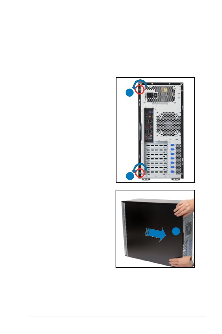
2.1.1 Removing the left side cover
You have to remove the left side cover to install or replace internal components of
the server system.
• Ensure that you unplug the power cord before removing the side cover.
• Take extra care when removing the side cover. Keep your ngers from
components inside the chassis that can cause injury, such as the CPU fan,
rear fan, and other sharp-edged parts.
To remove the left side cover
1. Remove the two screws that secure
the left side cover to the chassis.
2. Slide the left side cover for about
half an inch toward the rear until it
is disengaged from the chassis.
3. Carefully lift the cover and set it
aside.
2
1
1
2-3ASUS TW300-E5/PI4
2.1.2 Removing the right side cover
Most internal components can be installed or replaced after removing the left
side cover. However, for components such as Serial ATA hard disk drives, you
may have to remove the right side cover for easier component installation or
replacement.
To remove the right side cover
1. Remove the two screws that secure
the left side cover to the chassis.
2
2. Slide the right side cover for about
half an inch toward the rear until it
is disengaged from the chassis.
3. Carefully lift the cover and set it
aside.
1
1

Chapter 2: Hardware setup2-4
P5E WS PRO
®
2.2 Motherboard overview
The barebone server comes with the P5E WS Professional motherboard already
installed. The motherboard is secured to the chassis by nine (9) screws as
indicated by the circles in the illustration below.
Ensure to unplug the power cord before installing or removing any motherboard
component or connection. Failure to do so can cause you physical injury and
damage motherboard components.
Place this side towards
the rear of the chassis
Refer to for detailed information on the Chapter 3: Motherboard information
motherboard.

2-5ASUS TW300-E5/PI4
2.3.1 Installing the CPU
To install a CPU:
1. Locate the CPU socket on the motherboard.
2.3 Central Processing Unit (CPU)
The motherboard comes with a surface mount LGA775 socket designed for the
Intel® Xeon 3300 / 3200 / 3100 / 3000 Series processor in the 775-land package
2. Press the load lever with your thumb (A), then move it to the left (B) until it is
released from the retention tab.
Retention tab
Load lever
This side of the socket
box should face you.
PnP cap
A
B
To prevent damage to the socket pins, do not remove the PnP cap unless you
are installing a CPU.
Before installing the CPU, make sure that the socket box is facing towards you
and the load lever is on your left.
P5E WS PRO
®
P5E WS Professional CPU Socket 775

Chapter 2: Hardware setup2-6
3. Lift the load lever in the direction of
the arrow to a 135º angle.
4. Lift the load plate with your thumb
and forenger to a 100º angle (A),
then push the PnP cap from the load
plate window to remove (B).
5. Position the CPU over
the socket, making sure
that the gold triangle is
on the bottom-left corner
of the socket. The socket
alignment key should t
into the CPU notch. Alignment key
Gold triangle mark
Load plate
A
B
The CPU ts in only one correct orientation. DO NOT force the CPU into the
socket to prevent bending the connectors on the socket and damaging the CPU!
2-7ASUS TW300-E5/PI4
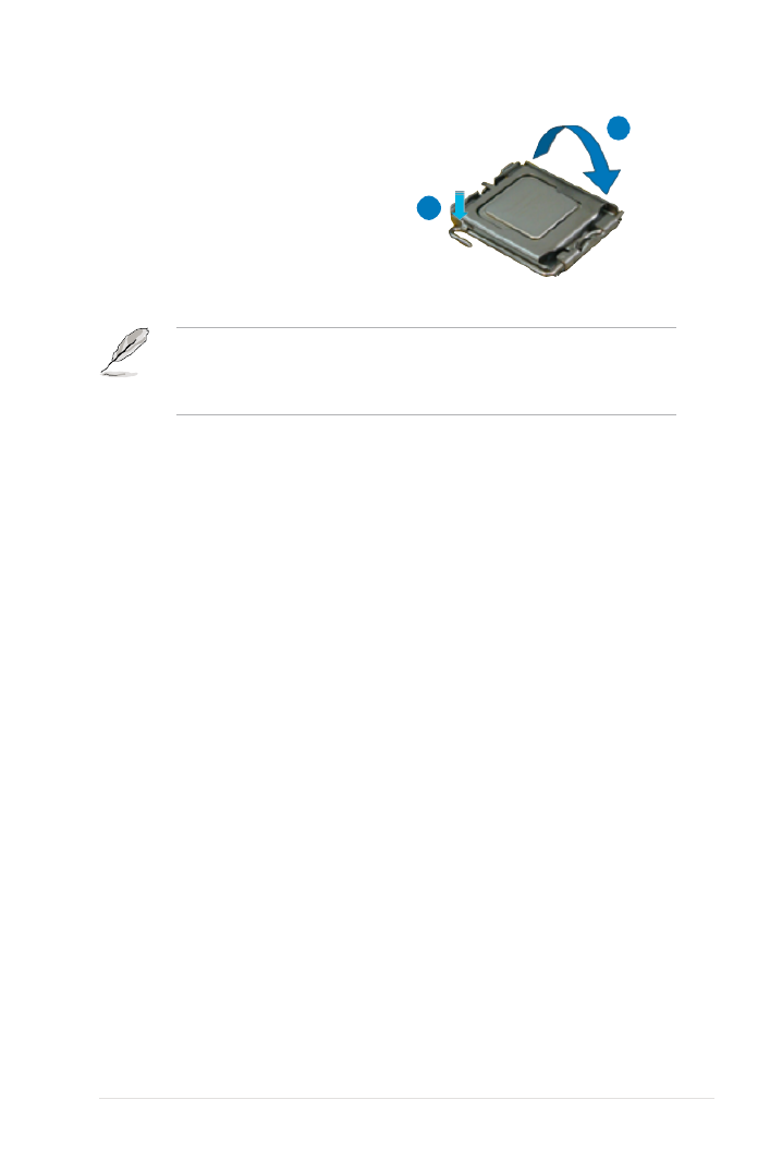
6. Close the load plate (A), then
push the load lever (B) until it
snaps into the retention tab.
A
B
The motherboard supports Intel ® Core 2 Extreme / Core 2 Quad / Core 2 Duo
Series LGA775 processors with the Intel
® Enhanced Memory 64 Technology
(EM64T), Enhanced Intel SpeedStep
® Technology (EIST), and Hyper-Threading
Technology. Refer to the Appendix for more information on these CPU features.

Chapter 2: Hardware setup2-8
To install the CPU cooler and fan
1. Place the cooler on top of the
installed CPU, making sure that the
four screws match the holes on the
support plate.
2.3.2 Installing the CPU heatsink
The Intel® Core™ 2 Extreme / Core™ 2 Quad / Core™ 2 Duo Series processors
require an Intel certied or ASUS qualied heatsink and fan assembly to ensure
optimum thermal condition and performance.
When you buy a boxed Intel CPU, the package includes the cooler, fan, retention
brackets, screws, thermal grease, installation manual, and other items that are
necessary for CPU installation.
• Ensure that you have applied the thermal grease to the top of the CPU
before installing the heatsink and fan.
• Refer to the installation manual that came with the CPU package for details
on heatsink/fan assmbly and installation.
2. Use a screwdriver to tighten the
four cooler screws in a diagonal
sequence.
A
A B
B

2-9ASUS TW300-E5/PI4
3. Connect the CPU fan cable to the
connector on the motherboard
labeled CPU_FAN.
Do not forget to connect the CPU_FAN connector! Hardware monitoring errors
can occur if you fail to plug this connector.
P5E WS PRO
®
P5E WS Professional CPU fan connector
CPU_FAN
GND
CPU F RAN PW
CPU FAN IN
CPU F MAN PW

Chapter 2: Hardware setup2-10
2.4 System memory
2.4.1 Overview
The motherboard comes with four Double Data Rate II (DDR2) Dual Inline Memory
Modules (DIMM) sockets to support 240-pin DDR2 modules.
The gure illustrates the location of the DDR2 DIMM sockets:
P5E WS PRO
®
P5E WS Professional 240-pin DDR2 DIMM sockets
DIMM_A2
DIMM_A1
DIMM_B2
DIMM_B1
Channel Sockets
Channel A DIMM_A1 and DIMM_A2
Channel B DIMM_B1 and DIMM_B2
This chipset ofcially supports DDR2 800/667MHz. With the ASUS Super
Memspeed Technology, the motherboard natively supports up to DDR2
1066MHz and provides more ratio setting items than the chipset ofcially
supports. Refer to the table below for details.
FSB 1333 1066
DDR2 1066 800 667 1066 800 667

2-11ASUS TW300-E5/PI4
64-bit
Windows® XP Professional x64 Edition
Windows® Vista x64 Edition
• Due to chipset limitation, this motherboard can only support up to
8 GB on the operating systems listed below. You may install a maximum of
2 GB DIMMs on each slot.
• Some old-version DDR2-800 DIMMs may not match Intel
®’s
On-Die-Termination (ODT) requirement and will automatically downgrade
to run at DDR2-667. If this happens, contact your memory vendor to check
the ODT value.
• Due to chipset limitation, DDR2-800 with CL=4 will be downgraded to run
at DDR2-667 by default setting. If you want to operate with lower latency,
adjust the memory timing manually.
2.4.2 Memorycongurations
You may install 256 MB, 512 MB, 1 GB, and 2 GB ECC and non-ECC, unbuffered
DDR2 DIMMs into the DIMM sockets.
• You may install varying memory sizes in Channel A and Channel B. The
system maps the total size of the lower-sized channel for the dual-channel
conguration. Any excess memory from the higher-sized channel is then
mapped for single-channel operation.
• Always install DIMMs with the same CAS latency. For optimum
compatibility, it is recommended that you obtain memory modules from the
same vendor.
• If you install four 1GB memory modules, the system may only recognize
less than 3GB of total memory because of address space allocation for
other critical functions. This limitation appears on Windows
® Vista 32-bit /
Windows® XP 32-bit operation systems since it does not support Physical
Address Extension (PAE) mode.
• If you install Windows® Vista 32-bit / Windows
® XP 32-bit operation system,
a total memory of less than 3GB is recommended.
• This motherboard does not support memory modules made up of 128 Mb
chips or double sided x16 memory modules.

Chapter 2: Hardware setup2-12
2.4.3 Installing a DIMM
To install a DIMM:
1. Unlock a DIMM socket by pressing
the retaining clips outward.
2. Align a DIMM on the socket
such that the notch on the DIMM
matches the break on the socket.
3. Firmly insert the DIMM into the
socket until the retaining clips snap
back in place and the DIMM is
properly seated.
2.4.4 Removing a DIMM
To remove a DIMM:
1. Simultaneously press the retaining
clips outward to unlock the DIMM.
2. Remove the DIMM from the socket.
• A DDR2 DIMM is keyed with a notch so that it ts in only one direction. Do
not force a DIMM into a socket to avoid damaging the DIMM.
• The DDR2 DIMM sockets do not support DDR DIMMs. DO not install DDR
DIMMs to the DDR2 DIMM sockets.
Unlocked retaining clip
DDR2 DIMM notch
Unplug the power supply before adding or removing DIMMs or other
system components. Failure to do so can cause severe damage to both the
motherboard and the components.
Support the DIMM lightly with
your ngers when pressing the
retaining clips. The DIMM might
get damaged when it ips out
with extra force.
DDR2 DIMM notch
1
2
3
1
1
2

2-13ASUS TW300-E5/PI4
2.5 Installing hard disk drives
The server system supports four Serial ATA hard disk drives through screw-free
hard disk drive holders.
To install a Serial ATA hard disk drive
1. Follow the instruction in section
2.1.2 Removing the right side
cover to remove the right side
cover.
2. Slightly push inward the HDD
holder handles to release the HDD
holder lock from the HDD bay, as
shown in the right gure.
3. Carefully pull the HDD holder out of
the HDD bay, as shown in the right
gure.
2
2
3
4. Locate the four pin caps on the
HDD holder. Align one side of the
HDD screw holes to one side of
the cage pin caps, as shown in the
right gure.
Pin cap
4
5. Follow the direction of the arrow in
the right gure and slightly bend
the HDD holder.

Chapter 2: Hardware setup2-14
6. Attach the other side of the HDD
screw holes to the cage pin caps,
as shown in the right gure.
7. Carefully insert the HDD holder
and push it all the way to the depth
of the bay until the cage handles x
to the HDD bay.

2-15ASUS TW300-E5/PI4
2.6 Installing 5.25-inch drives
Ensure to unplug the power cable before installing or removing any system
components. Failure to do so may cause severe damage to the motherboard
and other system components!
1
2
The system comes with two 5.25-inch
drive bays located on the upper front
part of the chassis. An optical drive that
comes standard/optional with the system
package occupies the uppermost bay
(labeled 1). The lower bay (labled 2) is
available for additional 5.25-inch optical,
zip, or oppy disk drives.
You must remove the front panel
cover before installing a
5.25-inch drive.
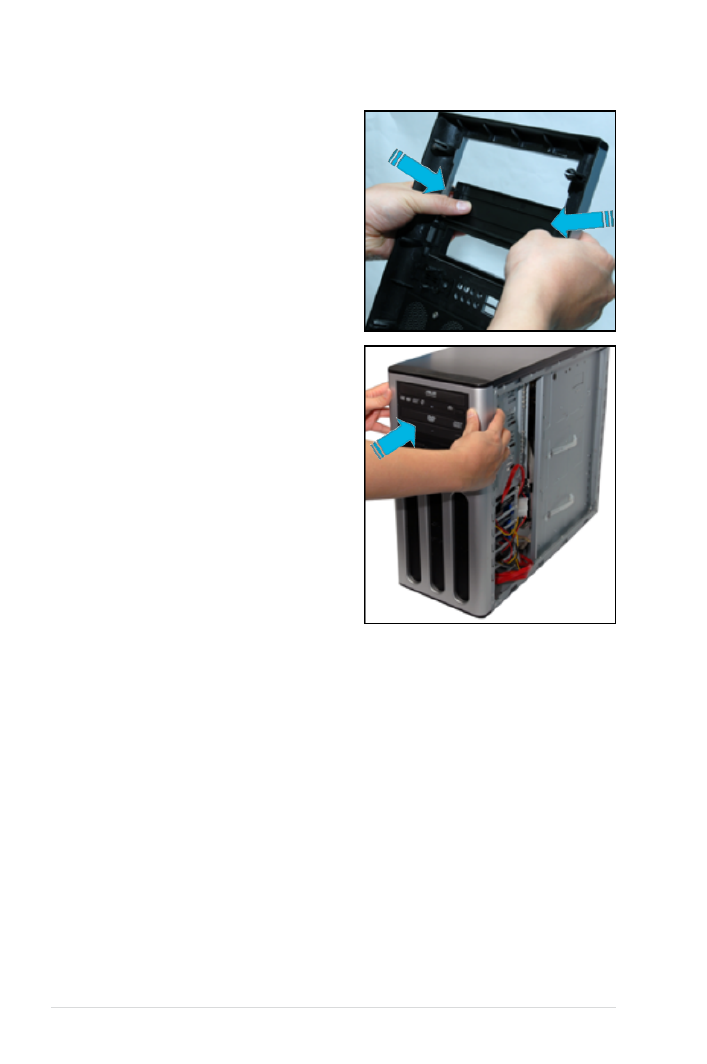
2.6.1 Removing the front panel cover
To remove the front panel cover
1. Follow the instructions in section
2.1 Chassis cover to remove both
the side covers.
2. Locate the front cover slot on the
bottom of the front cover.

Chapter 2: Hardware setup2-16
3. Carefully remove the front panel
cover, and then set aside.
2.6.2 Installing an additional optical drive
Congure your optical drive as Master/Slave device before installing it to the
drive bay. Refer to the optical drive documentation for details.
To install an additional optical drive
1. Select the drive bay you intend to
use. Push the knock down metal
cover in and out of the chassis until
it is removed.
Take extra care when removing
the knock down metal cover.
Use tools such as a screw driver
to bend and remove the metal
cover to avoid physical injury.

2-17ASUS TW300-E5/PI4
2. Follow the direction of the arrows in
the gure to unlock and lift the drive
bay lock.
3. Carefully insert the drive to the bay.
4. Align the drive to the bay screw
holes, and then lock the drive bay
lock.
5. Connect a 40-pin IDE cable (from
the rst optical drive) and a 4-pin
power plug (from the power supply
unit) to the connectors on the drive.
Chapter 2: Hardware setup2-18
6. Remove the front panel bay cover
opposite the drive bay you used by
pressing the hooks inward.
7. Reinstall the front panel and side
covers when done.

Chapter 2: Hardware setup2-20
6. Align the card connector with the
slot, then press rmly until the card
is completely seated on the slot.
7. Restore the expansion card lock
to its original position and push it
down until you hear a click sound.
2.7.2 Conguringanexpansioncard
After installing the expansion card, congure it by adjusting the software settings.
1. Turn on the system and change the necessary BIOS settings, if any. See
Chapter 4 for information on BIOS setup.
2. Assign an IRQ to the card. Refer to the tables on the next page.
3. Install the software drivers for the expansion card.
When using PCI cards on shared slots, ensure that the drivers support “Share
IRQ” or that the cards do not need IRQ assignments. Otherwise, conicts will
arise between the two PCI groups, making the system unstable and the card
inoperable. Refer to the table on the next page for details.

2-21ASUS TW300-E5/PI4
2.7.3 Interrupt assignments
IRQ assignments for this motherboard
A B C D E F G H
PCI Slot 1 Shared – – – – – – –
PCI Slot 2 – Shared – – – – – –
LAN 1 (8056) – – Shared – – – – –
LAN 2 (8056) – – – Shared – – – –
SATA (Marvell) Shared – – – – – – –
PCIe X16_1 Shared – – – – – – –
PCIe X16_2 Shared – – – – – – –
PCIe X1_1 – Shared – – – – – –
PCIX_1 – Shared – – – – – –
USB Controller 1 – – – – – – – Shared
USB Controller 2 – – – Shared – – – –
USB Controller 3 – – Shared – – – – –
USB Controller 4 Shared – – – – – – –
USB Controller 5 Shared – – – – – – –
USB Controller 6 – – – – – Shared – –
USB 2.0 Controller 1 – – – – – – – Shared
USB 2.0 Controller 2 – – Shared – – – – –
SATA Controller 1 – – Shared – – – – –
SATA Controller 2 – – – – – – Shared –
Azalia ALC888 – – – – – – Shared –
IRQ Priority Standard function
01 System timer
1 Keyboard controller2
2–Re-direct to IRQ#9
3 11 IRQ holder for PCI steering*
4 12 Communications port (COM1)*
5 IRQ holder for PCI steering*13
6 14 Floppy disk controller
715 IRQ holder for PCI steering*
8 3 System CMOS/Real Time Clock
94 IRQ holder for PCI steering*
10 5 IRQ holder for PCI steering*
11 6 IRQ holder for PCI steering*
12 PS/2 compatible mouse port*7
13 8 Numeric data processor
14 IRQ holder for PCI steering*9
15 10 IRQ holder for PCI steering*
* These IRQs are usually available for PCI devices.

Chapter 2: Hardware setup2-22
2.8 Removing components
You may need to remove previously installed system components when installing
or removing other system components, or when replacing a defective component.
This section tells how to remove the following components:
1. Floppy disk drive (FDD)
2. System fan
3. SATA backplane
2.8.1 Removingtheoppydiskdrive
To remove the FDD
1. Disconnect the FDD power plug
and signal cable.
3. Carefully pull the FDD bay from the
chassis.
4. Remove the four screws from the
FDD bay to release the FDD.

2-23ASUS TW300-E5/PI4
2.8.2 Removing the system fan
To remove the system fan
1. Disconnect the chassis fan cable from the CHA_FAN1 connector on the
motherboard.
2. Locate and remove four system fan
screws at the rear panel. Keep the
screws for later use.
Hold the system fan with one
hand while removing the system
screws.
3. Remove the system fan, and then
set aside.
P5E WS PRO
®
P5E WS Professional Fan connectors
CPU_FAN
CHA_FAN1
GND
Rotation
+12V
CHA_FAN2
PWR_FAN
GND
Rotation
+12V
GND
CPU F RAN PW
CPU FAN IN
CPU F MAN PW
GND
Rotation
+12V
Chapter 2: Hardware setup2-24
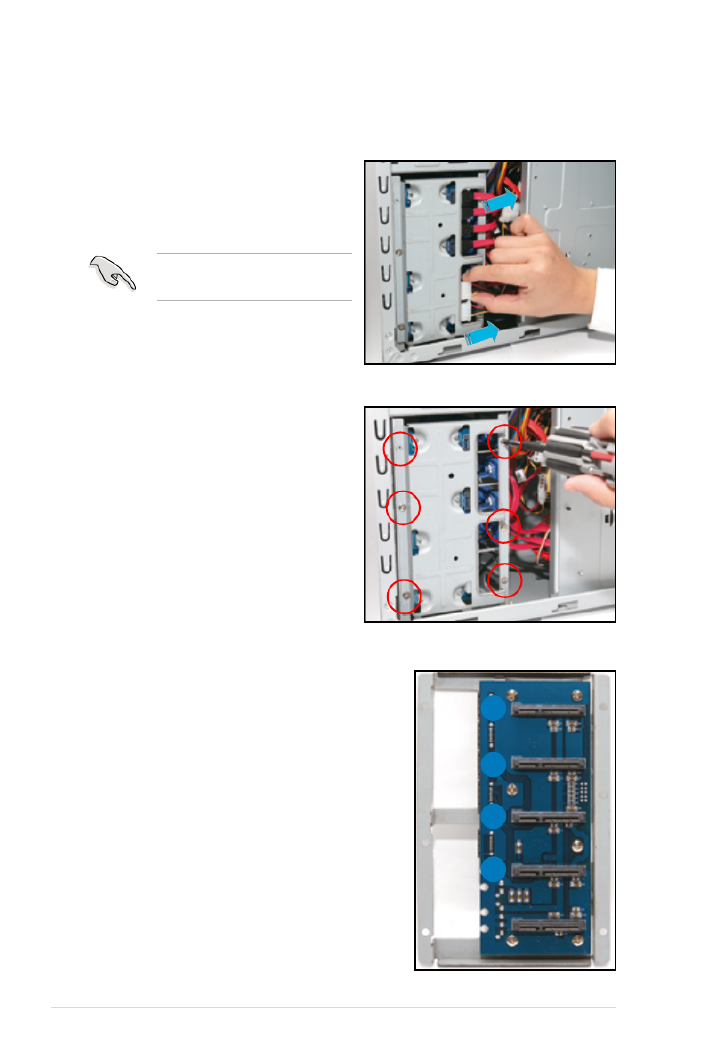
To remove the SATA backplane
1. Remove the right side cover rst.
Disconnect all SATA cables and
power cables connected to the
SATA backplane.
2.8.3 Removing the SATA backplane
Remove all hard drives before
removing the SATA backplane.
2. Remove all the six screws on the
back of the SATA backplane holder
with a screwdriver.
3. Take out the SATA backplane with
the backplane holder and place on
a at surface. The TW300-E5/PI4
Workstation uses only the four SATA
HDD connectors labelled DEVICE1-
4.
4
3
2
1

2-25ASUS TW300-E5/PI4
4. Remove all the six screws on
the holder to replace the SATA
backplane.

3-
ASUS TW300-E5/PI4
This chapter gives information about
the motherboard that comes with the
workstation. This chapter includes the
motherboard layout, jumper settings,
and connector locations.
Chapter 3
Motherboard info
Chapter 3: Motherboard information3-2
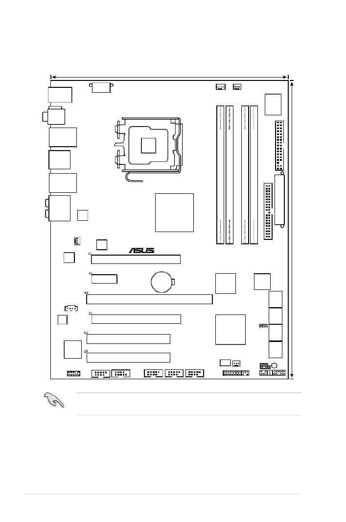
3.1 Motherboard layouts
P5E WS Professional Motherboard
PANEL
P5E WS PRO
®
AAFP CHASSIS
24.5cm (9.6in)
30.5cm (12.0in)
CPU_FAN
DDR2 DIMM_A1 (64 bit,240-pin module)
DDR2 DIMM_A2 (64 bit,240-pin module)
FLOPPY
Super
I/O
CD
PCIEX16_1
PCI2
CLRTC
SB_PWR
EATXPWR
CR2032 3V
Lithium Cell
CMOS Power
CHA_FAN2
COM1
EATX12V
LGA775
Intel®
X38
IE1394_2
PWR_FAN
Intel®
ICH9R
Marvell ®
88E8056
USB78
PCIEX1_1
PCIX_1
LAN2_USB34
KB_USB56
LAN1_USB12
AUDIO
F_ESATA12
SPDIF_O12
VIA
VT6308S
TPM
BIOS
CHA_FAN1
DET_X16_1
DET_X1_1
DET_PCIX_1
EXT_SATA2
EXT_SATA1
PCIEX16_2
USB910USB1112
PCIX_SPEED1
SATA2
SATA1
SATA4
SATA3
SATA6
SATA5
DDR2 DIMM_B1 (64 bit,240-pin module)
DDR2 DIMM_B2 (64 bit,240-pin module)
DET_PCI2
DET_X16_2
ALC888
PRI_IDE
Marvell®
88E6145
NEC
upd 720404
PCI1
DET_PCI1
Marvell
®
88E8056
ICS
Refer to for more information about rear panel connectors and 3.3 Connectors
internal connectors.
3-3ASUS TW300-E5/PI4
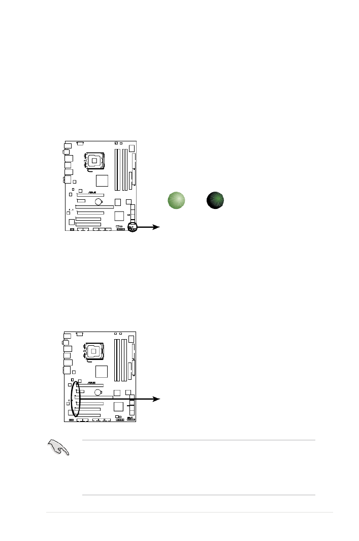
Onboard LED
The motherboard comes with a standby power LED that lights up to indicate that
the system is ON, in sleep mode, or in soft-off mode. This is a reminder that you
should shut down the system and unplug the power cable before removing or
plugging in any motherboard component. The illustration below shows the location
of the onboard LED.
P5E WS PRO
®
P5E WS Professional Onboard LED
SB_PWR
ON
Standby
Power
OFF
Powered
Off
AI Slot Detector
This motherboard comes with on-board LEDs that light up when the PCIE/PCI
devices are not correctly installed. When the power cord is plugged in and the
LED lights up, reinstall the device correctly. Refer to the gure on the right for the
location of the LEDs.
P5E WS PRO
®
P5E WS Professional Slot Detectors
DET_X16_1
DET_X1_1
DET_PCIX_1
DET_X16_2
DET_PCI1
DET_PCI2
• The PCIEx16_1-2 slots (blue) support PCIE x16 cards only. The AI Slot
Detector lights up when you install p49-x1 or p49-x4 cards to these slots.
• When the AI Slot Detector lights up for incorrect installation, make sure to
turn off the power supply unit before reinstaling the card to avoid electrical
shock hazard.

Chapter 3: Motherboard information3-4
Layout contents
Jumper Page
1. Clear RTC RAM (3-pin CLRTC_EN) 3-6
2. PCI-X Speed setting (3-pin PCIX_SPEED1) 3-7
Rear panel connectors Page
1. PS/2 keyboard port (purple) 3-8
2. Coaxial S/PDIF Out port 3-8
3. LAN 1 (RJ-45) port 3-8
4. IEEE 1394a port 3-8
5. LAN 2 (RJ-45) port 3-8
6. Center/Subwoofer port (orange) 3-8
7. Rear Speaker Out port (black) 3-8
8. Line In port (light blue) 3-8
9. Line Out port (lime) 3-8
10. Microphone port (pink) 3-9
11. Side Speaker Out port (gray) 3-9
12. USB 2.0 ports 3 and 4 3-9
13. External SATA ports 3-9
14. USB 2.0 ports 1 and 2 3-10
15. Optical S/PDIF Out port 3-10
16. USB 2.0 ports 5 and 6 3-10

3-5ASUS TW300-E5/PI4
Internal connectors Page
1. Floppy disk drive connector (34-1 pin FLOPPY) 3-11
2. IDE connector (40-1 pin PRI_IDE 3-12)
3. ICH9R Serial ATA connectors [blue] (7-pin SATA1-6) 3-13
4. Marvell® 88SE6145 Serial ATA RAID connectors [black] (7-pin
EXT_SATA1-2)
3-14
5. USB connectors (10-1 pin USB78, USB910, USB1112 3-15)
6. IEEE 1394a port connector (10-1 pin IE1394_1 3-15)
7. Optical audio drive connector (4-pin CD) 3-16
8. Serial port ) connector (10-1 pin COM1 3-16
9. CPU, chassis, and power fan connectors (4-pin CPU_FAN,
3-pin CHA_FAN1-2, 3-pin PWR_FAN)
3-17
10. Chassis intrusion connector (4-1 pin CHASSIS) 3-17
11. Front panel audio connector (10-1 pin AAFP) 3-18
12. TPM connector (20-1 pin TPM) 3-18
13. ATX power connectors (24-pin EATXPWR, 8-pin EATX12V) 3-19
14. System panel connector (20-8-pin PANEL)3-20
15. ASUS Q-connector (system panel) 3-21
3-7ASUS TW300-E5/PI4
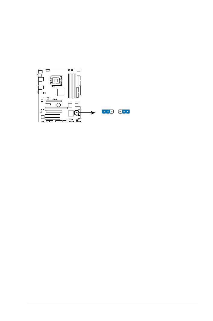
2. PCI-X Speed setting (3-pin PCIX_SPEED1)
This jumper allows you to set the PCI-X slot’s maximum frequency capability.
Thejumpercaponpins1-2: 133 MHz capability for the PCI-X slot.
Thejumpercaponpins2-3: 100 MHz capability for the PCI-X slot.
P5E WS PRO
®
32
P5E WS Professional PCIX speed setting
PCIX_SPEED1
100MHz133MHz
(Default)
1 2

3-9ASUS TW300-E5/PI4
10. Microphone port (pink). This port connects a microphone.
11. Side Speaker Out port (gray). This port connects the side speakers in an
8-channel audio conguration.
12. USB 2.0 ports 3 and 4. These two 4-pin Universal Serial Bus (USB) ports
are available for connecting USB 2.0 devices.
13. External SATA ports . These ports connect to external Serial ATA hard disk
drives. To congure a RAID 0, 1, 5 or 10 set, install an external Serial ATA
hard disk drive to the external Serial ATA port and an internal Serial ATA
hard disk drive to the onboard Serial ATA connectors labeled EXT_SATA1 or
EXT_SATA2.
Refer to the audio conguration table below for the function of the audio ports in
2, 4, 6, or 8-channel conguration.
Audio2,4,6,or8-channelconguration
Port Headset
2-channel 4-channel 6-channel 8-channel
Light Blue Line In Line In Line In Line In
Lime Line Out Front Speaker Out Front Speaker Out Front Speaker Out
Pink Mic In Mic In Mic In Mic In
Orange – – Center/Subwoofer Center/Subwoofer
Black – Rear Speaker Out Rear Speaker Ou Rear Speaker Out
Gray – – – Side Speaker Out
• Before creating a RAID set using Serial ATA hard disks, make sure that you
have connected the Serial ATA signal cables and installed Serial ATA hard
disk drives; otherwise, you cannot enter the Marvell RAID utility and SATA
setup during POST.
• If you intend to create a RAID conguration using one of these connectors,
set the Marvell SATA/PATA Controller item in the BIOS to [RAID Mode].
See section for details. 4.5.3OnBoardDevicesConguration
The external SATA ports
support external Serial ATA
3.0 Gb/s devices. Longer
cables support higher power
requirements to deliver signal
up to two meters away, and
enables improved hot-swap
function.

Chapter 3: Motherboard information3-10
14. USB 2.0 ports 1 and 2 . These two 4-pin Universal Serial Bus (USB) ports
are available for connecting USB 2.0 devices.
15. Optical S/PDIF Out port. This port connects an external audio output device
via an optical S/PDIF cable.
16. USB 2.0 ports 5 and 6. These two 4-pin Universal Serial Bus (USB) ports
are available for connecting USB 2.0 devices.
• DO NOT insert different connectors to these ports.
• DO NOT unplug the external Serial ATA box when a RAID 0 or RAID 1 is
congured.

3-11ASUS TW300-E5/PI4
3.3.2 Internal connectors
1. Floppy disk drive connector (34–1 pin FLOPPY1)
This connector is for the provided Floppy Disk Drive (FDD) signal cable.
Insert one end of the cable to this connector, then connect the other end to
the signal connector at the back of the oppy disk drive.
Pin 5 on the connector is removed to prevent incorrect cable connection when
using a FDD cable with a covered Pin 5.
P5E WS PRO
®
P5E WS Professional Floppy disk drive connector
NOTE: Orient the red markings on
the floppy ribbon cable to PIN 1.
PIN 1
FLOPPY

Chapter 3: Motherboard information3-12
• Pin 20 on the IDE connector is removed to match the covered hole on
the Ultra ATA cable connector. This prevents incorrect insertion when you
connect the IDE cable.
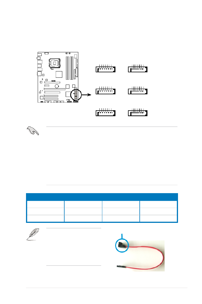
• Use the 80 conductor IDE cable for Ultra ATA 100/66/33 IDE devices.–
Drivejumpersetting Mode of
device(s) Cable connector
Single device Cable-Select or Master - Black
Two devices
Cable-Select Master Black
Slave Gray
Master Master Black or gray
Slave Slave
If any device jumper is set as “Cable-Select,” make sure all other device
jumpers have the same setting.
P5E WS PRO
®
P5E WS Professional IDE connector
NOTE: Orient the red markings
(usually zigzag) on the IDE
ribbon cable to PIN 1.
PRI_IDE
PIN 1
2. IDE connector (40-1 pin PRI_IDE)
The onboard IDE connector is for the Ultra DMA 133/100 signal cable. There
are three connectors on each Ultra DMA 133/100 signal cable: blue, black,
and gray. Connect the blue connector to the motherboard’s IDE connector,
then select one of the following modes to congure your device.
3-13ASUS TW300-E5/PI4
3. ICH9R Serial ATA connectors [blue] (7-pin SATA1-6)
These connectors are for the Serial ATA signal cables for Serial ATA hard disk
drives and optical disk drives.
• When using the connectors in Standard IDE mode, connect the primary
(boot) hard disk drive to the SATA1/2 connector. Refer to the table below
for the recommended SATA hard disk drive connections.
• These connectors are set to Standard IDE mode by default. In Standard
IDE mode, you can connect Serial ATA boot/data hard drives to these
connectors. If you intend to create a Serial ATA RAID set using these
connectors, set the Congure SATA as item in the BIOS to [RAID]. See
section 4.3.6SATAConguration for details.
• Before creating a RAID set, refer to 5.1RAIDCongurations or the
manual bundled in the motherboard support DVD.
P5E WS PRO
®
P5E WS Professional
SATA connectors
SATA ATA12 S
GND
RSATA_TXP2
RSATA_TXN2
GND
RSATA_RXP2
RSATA_RXN2
GND
GND
RSATA_TXP1
RSATA_TXN1
GND
RSATA_RXP1
RSATA_RXN1
GND
SATA3 SATA4
GND
RSATA_TXP3
RSATA_TXN3
GND
RSATA_RXP3
RSATA_RXN3
GND
GND
RSATA_TXP4
RSATA_TXN4
GND
RSATA_RXP4
RSATA_RXN4
GND
SATA AT6 S A5
GND
RSATA_TXP6
RSATA_TXN6
GND
RSATA_RXP6
RSATA_RXN6
GND
GND
RSATA_TXP5
RSATA_TXN5
GND
RSATA_RXP5
RSATA_RXN5
GND
Serial ATA hard disk drive connection
Connector Color Setting Use
SATA 1/2 Blue Boot diskMaster
SATA 3/4 Blue Boot/Data diskSlave
SATA 5/6 Blue Boot diskMaster
Connect the right-angle side
of SATA signal cable to SATA
device. Or you may connect the
right-angle side of SATA cable to
the onboard SATA port to avoid
mechanical conict with huge
graphics cards.
Right angle side

Chapter 3: Motherboard information3-14
4. Marvell ® 88SE6145 Serial ATA RAID connectors [black] (7-pin
EXT_SATA1-2)
These connectors are for Serial ATA signal cables that support Serial ATA
hard disk drives. To congure RAID 0, RAID 1, RAID 5 or RAID 10, install an
internal Serial ATA hard disk drive to one of these connectors and an external
Serial ATA drive to one of the external SATA ports.
Before creating a RAID set using Serial ATA hard disks, make sure that you
have connected the Serial ATA signal cables and installed Serial ATA hard disk
drives; otherwise, you cannot enter the Marvell RAID utility and SATA BIOS
setup during POST.
P5E WS PRO
®
P5E WS Professional EXT_SATA connectors
EXT_SATA2 EXT_SATA1
GND
RSATA_TXP2
RSATA_TXN2
GND
RSATA_RXP2
RSATA_RXN2
GND
GND
RSATA_TXP1
RSATA_TXN1
GND
RSATA_RXP1
RSATA_RXN1
GND
• Please install the Marvell® Controller driver before using the black Serial
ATA RAID connectors (EXT_SATA1-2). Refer to 6.2.4 Make Disk menu for
details.
• If you intend to create a RAID conguration using one of the Marvell
® Serial
ATA RAID connectors and one of the external SATA ports, it is strongly
recommended to install the OS on the internal hard disk drive and use the
external hard disk drive as a data disk.

3-15ASUS TW300-E5/PI4
5. USB connectors (10-1 pin USB78, USB910, USB1112)
These connectors are for USB 2.0 ports. Connect the USB module cable
to any of these connectors, then install the module to a slot opening at the
back of the system chassis. These USB connectors comply with USB 2.0
specication that supports up to 480 Mbps connection speed.
You can connect the USB cable to ASUS Q-Connector (USB, blue) rst, and
then install the Q-Connector (USB) to the USB connector onboard.
Never connect a 1394 cable to the USB connectors. Doing so will damage the
motherboard!
P5E WS PRO
®
P5E WS Professional
USB 2.0 connectors
USB1112
USB+5V
USB_P12-
USB_P12+
GND
NC
USB+5V
USB_P11-
USB_P11+
GND
USB910
USB+5V
USB_P10-
USB_P10+
GND
NC
USB+5V
USB_P9-
USB_P9+
GND
USB78
USB+5V
USB_P8-
USB_P8+
GND
NC
USB+5V
USB_P7-
USB_P7+
GND
6. IEEE 1394a port connector (10-1 pin IE1394_1)
This connector is for an IEEE 1394a port. Connect the IEEE 1394a module
cable to this connector, then install the module to a slot opening at the back
of the system chassis.
Never connect a USB cable to the IEEE 1394a connector. Doing so will damage
the motherboard!
You can connect the 1394 cable to ASUS Q-Connector (1394, red) rst, and
then install the Q-Connector (1394) to the 1394 connector onboard.
P5E WS PRO
®
P5E WS Professional
IEEE 1394a connector
IE1394_1
PIN 1
GND
+12V
TPB1-
GND
TPA1-
+12V
TPB1+
GND
TPA1+

Chapter 3: Motherboard information3-16
7. Optical drive audio connector (4-pin CD)
These connectors allow you to receive stereo audio input from sound sources
such as a CD-ROM, TV tuner, or MPEG card.
8. Serial port connector (10-1 pin COM1)
This connector is for a serial (COM) port. Connect the serial port module
cable to this connector, then install the module to a slot opening at the back
of the system chassis.
P5E WS PRO
®
P5E WS Professional Internal audio connector
CD
Right Audio Channel
Left Audio Channel
Ground
Ground
P5E WS PRO
®
P5E WS Professional COM port connector
PIN 1
COM1

Chapter 3: Motherboard information3-18
11. Front panel audio connector (10-1 pin AAFP)
This connector is for a chassis-mounted front panel audio I/O module that
supports either HD Audio or legacy AC`97 audio standard. Connect one end
of the front panel audio I/O module cable to this connector.
•
We recommend that you connect a high-denition front panel audio module
to this connector to avail of the motherboard’s high-denition audio capability.
• By default, this connector is set to [HD Audio]. If you want to connect an
AC'97 front panel audio module to this connector, set the Front Panel
Type [AC'97] 4.5.3 Onboard item in the BIOS setup to . See section
DevicesConguration for details.
P5E WS PRO
®
P5E WS Professional Analog front panel connector
AAFP
Legacy AC 97 audio
pin definition
SENSE2_RETUR
PORT1 L
PORT2 R
PORT2 L
SENSE1_RETUR
SENSE_SEND
PORT1 RPRESENCE#
GND
NC
MIC2
Line out_R
Line out_L
NC
NC
MICPWRNC
AGND
HD Audio-compliant
pin definition
12. TPM connector (20-1 pin TPM) [Optional]
This connector supports a Trusted Platform Module (TPM) system, which can
securely store keys, digital certicates, passwords, and data. A TPM system
also helps enhance network security, protects digital identities, and ensures
platform integrity.
P5E WS PRO
®
P5E WS Professional TPM connector
TPM

3-19ASUS TW300-E5/PI4
•
For a fully congured system, we recommend that you use a power supply
unit (PSU) that complies with ATX 12 V Specication 2.0 (or later version)
and provides a minimum power of 400 W.
• Do not forget to connect the 8-pin EATX12V power plug; otherwise, the
system will not boot.
• Use of a PSU with a higher power output is recommended when
conguring a system with more power-consuming devices. The system
may become unstable or may not boot up if the power is inadequate.
• If you want to use two high-end PCI Express x16 cards, use a PSU with
500W to 600W power or above to ensure the system stability.
• If you are uncertain about the minimum power supply requirement for your
system, refer to the Recommended Power Supply Wattage Calculator
at http://support.asus.com/PowerSupplyCalculator/PSCalculator.
aspx?SLanguage=en-us for details.
13. ATX power connectors (24-pin EATXPWR, 8-pin EATX12V)
These connectors are for ATX power supply plugs. The power supply plugs
are designed to t these connectors in only one orientation. Find the proper
orientation and push down rmly until the connectors completely t.
P5E WS PRO
®
P5E WS Professional ATX power connectors
EATXPWR
+3 Volts
+3 Volts
Ground
+5 Volts
+5 Volts
Ground
Ground
Power OK
+5V Standby
+12 Volts +5 Volts
+3 Volts
-12 Volts
Ground
Ground
Ground
PSON#
Ground
+5 Volts
+12 Volts
+3 Volts
+5 Volts
Ground
EATX12V
GND +12V DC
GND +12V DC
GND +12V DC
GND +12V DC

Chapter 3: Motherboard information3-20
•
System power LED (2-pin PLED)
This 2-pin connector is for the system power LED. Connect the chassis
power LED cable to this connector. The system power LED lights up when
you turn on the system power, and blinks when the system is in sleep mode.
•
Hard disk drive activity LED (2-pin IDE_LED)
This 2-pin connector is for the HDD Activity LED. Connect the HDD Activity
LED cable to this connector. The IDE LED lights up or ashes when data is
read from or written to the HDD.
•
System warning speaker (4-pin SPEAKER)
This 4-pin connector is for the chassis-mounted system warning speaker. The
speaker allows you to hear system beeps and warnings.
•
ATX power button/soft-off button (2-pin PWRSW)
This connector is for the system power button. Pressing the power button
turns the system on or puts the system in sleep or soft-off mode depending
on the BIOS settings. Pressing the power switch for more than four seconds
while the system is ON turns the system OFF.
•
Reset button (2-pin RESET)
This 2-pin connector is for the chassis-mounted reset button for system
reboot without turning off the system power.
14. System panel connector (20-8 pin PANEL)
This connector supports several chassis-mounted functions.
P5E WS PRO
®
P5E WS Professional System panel connector
* Requires an ATX power supply.
PANEL
PLED-
PWR
+5V
Speaker
Ground
RESET
Ground
Reset
Ground
Ground
PWRSW
PLED+
IDE_LED-
IDE_LED+
IDE_LED
PLED SPEAKER

3-21ASUS TW300-E5/PI4
15. Q-Connector (system panel)
You can use ASUS Q-Connector to connect / disconnect chassis front panel
cables by only a few steps. Directions below shows how to install ASUS Q-
Connector.
Step2.
Properly install the ASUS Q-Connector to the
System panel connctor.
Step1.
Connect correct front panel to ASUS
Q-Connector rst. You can refer to the
marking on Q-Connector itself to know the
detail pin denition.
Step3.
Front panel functions are enabled.

Chapter 3: Motherboard information3-22
3-
ASUS TW300-E5/PI4
This chapter tells how to change
system settings through the BIOS
Setup menus and describes the BIOS
parameters.
Chapter 4
BIOS information

Chapter 4: BIOS setup4-2
4.1 Managing and updating your BIOS
The following utilities allow you to manage and update the motherboard Basic
Input/Output System (BIOS) setup.
1. ASUS Update (Updates the BIOS in Windows
® environment.)
2. (Updates the BIOS using a oppy disk or USB ash disk.)ASUS EZ Flash 2
3. ASUS AFUDOS (Updates the BIOS using a bootable oppy disk.)
4. (Updates the BIOS using a bootable oppy disk, ASUS CrashFree BIOS 3
USB ash disk or the motherboard support DVD when the BIOS le fails or
gets corrupted.)
Refer to the corresponding sections for details on these utilities.
Save a copy of the original motherboard BIOS le to a bootable oppy disk or
USB ash disk in case you need to restore the BIOS in the future. Copy the
original motherboard BIOS using the ASUS Update or AFUDOS utilities.
Installing ASUS Update
To install ASUS Update:
1. Place the support DVD in the optical drive. The Drivers menu appears.
2. Click the Utilities tab, then click Install ASUS Update VX.XX.XX.
3. The ASUS Update utility is copied to your system.
4.1.1 ASUS Update utility
The ASUS Update is a utility that allows you to manage, save, and update the
motherboard BIOS in Windows® environment. The ASUS Update utility allows you
to:
• Save the current BIOS le
• Download the latest BIOS le from the Internet
• Update the BIOS from an updated BIOS le
• Update the BIOS directly from the Internet, and
• View the BIOS version information.
This utility is available in the support DVD that comes with the motherboard
package.
ASUS Update requires an Internet connection either through a network or an
Internet Service Provider (ISP).

4-3ASUS TW300-E5/PI4
Quit all Windows® applications before you update the BIOS using this utility.
3. Select the ASUS FTP site nearest
you to avoid network trafc, or
click . Click .Auto Select Next
Updating the BIOS through the Internet
To update the BIOS through the Internet:
1. Launch the ASUS Update utility from the Windows
® desktop by clicking Start
> Programs > ASUS > ASUSUpdate > ASUSUpdate. The ASUS Update
main window appears.
2. Select Update BIOS from the
Internet option from the drop-down
menu, then click .Next

Chapter 4: BIOS setup4-4
UpdatingtheBIOSthroughaBIOSle
To update the BIOS through a BIOS le:
1. Launch the ASUS Update utility from the Windows
® desktop by clicking Start
> Programs > ASUS > ASUSUpdate > ASUSUpdate. The ASUS Update
main window appears.
2. Select Update BIOS from a le
option from the drop-down menu,
then click .Next
4. From the FTP site, select the BIOS
version that you wish to download.
Click .Next
5. Follow the screen instructions to
complete the update process.
The ASUS Update utility is
capable of updating itself through
the Internet. Always update the
utility to avail all its features.
3. Locate the BIOS le from the Open
window, then click .Open
4. Follow the screen instructions to
complete the update process.
P5EWP
P5EWP.rom

Chapter 4: BIOS setup4-6
4.1.3 ASUS EZ Flash 2 utility
The ASUS EZ Flash 2 feature allows you to update the BIOS without having to go
through the long process of booting from a oppy disk and using a DOS-based
utility. The EZ Flash 2 utility is built in the BIOS chip so it is accessible by pressing
<Alt> + <F2> during the Power-On Self Tests (POST).
To update the BIOS using EZ Flash 2
1. Visit the ASUS website (www.asus.com) to download the latest BIOS le for
the motherboard.
2. Save the BIOS le to a oppy disk or a USB ash disk, then restart the
system.
3. You can launch the EZ Flash 2 by two methods.
(1) Insert the oppy disk / USB ash disk that contains the BIOS le to the
oppy disk drive or the USB port.
Press <Alt> + <F2> during POST to display the following.
(2) Enter BIOS setup program. Go to the Tools EZ Flash 2 menu to select
and press <Enter> to enable it.
You can switch between drives by pressing <Tab> before the correct le
is found. Then press <Enter>.
4. When the correct BIOS le is found, EZ Flash 2 performs the BIOS update
process and automatically reboots the system when done.
• This function can support devices such as a USB ash disk or a oppy disk
with FAT 32/16 format and single partition only.
• Do not shut down or reset the system while updating the BIOS to prevent
system boot failure!
ASUSTek EZ Flash 2 BIOS ROM Utility V3.06
Current ROM Update ROM
A:
Note
[Enter] Select or Load [B] Backup [ESC] Exit
[Tab] Switch [Up/Down/Home/End] Move
FLASH TYPE: WINBOND W25P/X16
PATH: A:\
BOARD: P5E WS Pro
VER: 0123
DATE: 08/27/07
BOARD: Unknown
VER: Unknown
DATE: Unknown

4-7ASUS TW300-E5/PI4
4.1.4 AFUDOS utility
The AFUDOS utility allows you to update the BIOS le in DOS environment using
a bootable oppy disk with the updated BIOS le. This utility also allows you to
copy the current BIOS le that you can use as backup when the BIOS fails or gets
corrupted during the updating process.
Copying the current BIOS
To copy the current BIOS le using the AFUDOS utility:
Mainlename Extension name
1. Copy the AFUDOS utility (afudos.exe) from the motherboard support DVD to
the bootable oppy disk you created earlier.
2. Boot the system in DOS mode, then at the prompt type:
afudos /o[lename]
where the [lename] is any user-assigned lename not more than eight
alphanumeric characters for the main lename and three alphanumeric
characters for the extension name.
A:\>afudos /oOLDBIOS1.rom
• Make sure that the oppy disk is not write-protected and has at least
1024KB free space to save the le.
• The succeeding BIOS screens are for reference only. The actual BIOS
screen displays may not be same as shown.
3. Press <Enter>. The utility copies the current BIOS le to the oppy disk.
A:\>afudos /oOLDBIOS1.rom
AMI Firmware Update Utility - Version 1.19(ASUS V2.07(03.11.24BB))
Copyright (C) 2002 American Megatrends, Inc. All rights reserved.
Reading ash ..... done
Write to le...... ok
A:\>
The utility returns to the DOS prompt after copying the current BIOS le.
UpdatingtheBIOSle
To update the BIOS le using the AFUDOS utility:
1. Visit the ASUS website (www.asus.com) and download the latest BIOS le for
the motherboard. Save the BIOS le to a bootable oppy disk.

Chapter 4: BIOS setup4-8
2. Copy the AFUDOS utility (afudos.exe) from the motherboard support DVD to
the bootable oppy disk you created earlier.
3. Boot the system in DOS mode, then at the prompt type:
afudos /i[lename]
where [lename] is the latest or the original BIOS le on the bootable oppy
disk.
A:\>afudos /iP5EWP.ROM
Write the BIOS lename on a piece of paper. You need to type the exact BIOS
lename at the DOS prompt.
5. The utility returns to the DOS prompt after the BIOS update process is
completed. Reboot the system from the hard disk drive.
A:\>afudos /iP5EWP.ROM
AMI Firmware Update Utility - Version 1.19(ASUS V2.07(03.11.24BB))
Copyright (C) 2002 American Megatrends, Inc. All rights reserved.
WARNING!! Do not turn off power during ash BIOS
Reading le ....... done
Reading ash ...... done
Advance Check ......
Erasing ash ...... done
Writing ash ...... done
Verifying ash .... done
Please restart your computer
A:\>
A:\>afudos /iP5EWP.ROM
AMI Firmware Update Utility - Version 1.19(ASUS V2.07(03.11.24BB))
Copyright (C) 2002 American Megatrends, Inc. All rights reserved.
WARNING!! Do not turn off power during ash BIOS
Reading le ....... done
Reading ash ...... done
Advance Check ......
Erasing ash ...... done
Writing ash ...... 0x0008CC00 (9%)
4. The utility veries the le and starts updating the BIOS.
Do not shut down or reset the system while updating the BIOS to prevent
system boot failure!

4-9ASUS TW300-E5/PI4
4.1.5 ASUS CrashFree BIOS 3 utility
The ASUS CrashFree BIOS 3 is an auto recovery tool that allows you to restore
the BIOS le when it fails or gets corrupted during the updating process. You can
update a corrupted BIOS le using the motherboard support DVD or the USB ash
disk that contains the updated BIOS le.
Prepare the motherboard support DVD, the oppy disk or the USB ash disk
containing the updated motherboard BIOS before using this utility.
Recovering the BIOS from the support DVD
To recover the BIOS from the support DVD
1. Turn on the system.
2. Insert the motherboard support DVD to the optical drive.
3. The utility displays the following message and automatically checks the DVD
for the BIOS le.
4. Restart the system after the utility completes the updating process.
When found, the utility reads the BIOS le and starts ashing the corrupted
BIOS le.
Bad BIOS checksum. Starting BIOS recovery...
Checking for oppy...
Bad BIOS checksum. Starting BIOS recovery...
Checking for oppy...
Floppy found!
Reading le “P5EWP.ROM”. Completed.
Start ashing...
RecoveringtheBIOSfromtheUSBashdisk
To recover the BIOS from the USB ash disk:
1. Insert the USB ash disk that contains the BIOS le to the USB port.
2. Turn on the system.
3. The utility will automatically checks the devices for the BIOS le. When
found, the utility reads the BIOS le and starts ashing the corrupted BIOS
le.
4. Restart the system after the utility completes the updating process.
• Only the USB ash disk with FAT 32/16 format and single partition can
support ASUS CrashFree BIOS 3. The device size should be smaller than
8GB.
• DO NOT shut down or reset the system while updating the BIOS! Doing so
can cause system boot failure!
Product specificaties
| Merk: | Asus |
| Categorie: | Server |
| Model: | TW300-E5/PI4 |
| Gewicht: | 16000 g |
| Processorfamilie: | Intel |
| Aantal USB 2.0-poorten: | 8 |
| Microfoon, line-in ingang: | Ja |
| Aantal Ethernet LAN (RJ-45)-poorten: | 2 |
| Hoofdtelefoonuitgangen: | 1 |
| Certificering: | UL1950-CSA950, TUV, FCC, CFR47 Part 15, Class B, CE, EN55022 & EN55024, C-TICK, BSMI, CCC |
| Netvoeding: | 450 W |
| Temperatuur bij opslag: | -40 - 70 °C |
| Processor socket: | LGA 775 (Socket T) |
| Maximum intern geheugen: | 8 GB |
| Compatibele besturingssystemen: | Windows XP Professional 32-bit, Windows XP Professional x64, Windows Vista Business 32-bit, Windows Vista Business 64-bit, RedHat Linux V5.1 |
| Netwerkfuncties: | 2 x Marvell 8056 PCI-E GbE LAN |
| Type behuizing: | Full-Tower |
| Aantal geïnstalleerde processoren: | 1 |
| Aantal IEEE 1394-/Firewire-poorten: | 1 |
| S/PDIF-uitgang: | Ja |
| Afmetingen (B x D x H): | 207 x 517 x 441 mm |
| PS/2 poort(en): | 1 |
| Uitbreidingsslots: | 2 x PCI-E 2.0 x 16 (x 16 link), \n1 x PCI-E x 1 (x 1 link), \n1 x PCI-X 64-bit/133MHz, \n2 x PCI 32-bit/33MHz (5V) |
| Harde schijf-controller: | Intel ICH9R |
| Interne schijfposities: | 4 x Easy-Swap SATA |
| Ondersteunde processor frequentie ( max): | 1.333 GHz |
| Aantal storage drives ondersteund: | 6 |
| Aantal eSATA-poorten: | 2 |
| Bedrijfstemperatuur (T-T): | 10 - 35 °C |
| Relatieve vochtigheid in bedrijf (V-V): | 20 - 90 procent |
| Aantal SATA-aansluitingen: | 6 |
Heb je hulp nodig?
Als je hulp nodig hebt met Asus TW300-E5/PI4 stel dan hieronder een vraag en andere gebruikers zullen je antwoorden
Handleiding Server Asus

2 April 2025
9 December 2024
26 Februari 2024
16 November 2023
16 November 2023
4 Juli 2023
21 Juni 2023
20 Juni 2023
1 Juni 2023
25 Mei 2023
Handleiding Server
- Server HP
- Server Sony
- Server Medion
- Server Toshiba
- Server Abus
- Server Acer
- Server Acti
- Server Allnet
- Server Apc
- Server Asrock
- Server Axis
- Server Buffalo
- Server D-Link
- Server Dell
- Server Digi
- Server Digitus
- Server Dual Bay
- Server Eaton
- Server Elac
- Server EMC
- Server Fantec
- Server Flir
- Server Freecom
- Server Fujitsu
- Server GeoVision
- Server Gigabyte
- Server Hikvision
- Server Ibm
- Server In Win
- Server Iomega
- Server Kathrein
- Server LaCie
- Server Lenovo
- Server LevelOne
- Server Linksys
- Server Luxman
- Server Maxdata
- Server Megasat
- Server Monacor
- Server MSI
- Server Nec
- Server Netgear
- Server Provision ISR
- Server QNAP
- Server Quantum
- Server Revox
- Server Seagate
- Server Sitecom
- Server Sun
- Server Synology
- Server Technics
- Server Trendnet
- Server Veritas
- Server Western Digital
- Server ZyXEL
- Server Conceptronic
- Server Atlona
- Server SilverStone
- Server Intel
- Server SIIG
- Server Tripp Lite
- Server Valcom
- Server Cisco
- Server Matrox
- Server Asustor
- Server Gefen
- Server Planet
- Server Intellinet
- Server Silex
- Server Supermicro
- Server G-Technology
- Server Lindy
- Server AVerMedia
- Server Black Box
- Server Blackmagic Design
- Server ATen
- Server Extron
- Server Areca
- Server AMX
- Server SEH
- Server StarTech.com
- Server HGST
- Server Sonnet
- Server TAIDEN
- Server Advantech
- Server Moxa
- Server Smart-AVI
- Server Kramer
- Server KanexPro
- Server Avocent
- Server Teradek
- Server Vimar
- Server Hanwha
- Server Ernitec
- Server MvixUSA
- Server Promise Technology
- Server Raidsonic
- Server Rocstor
- Server Infortrend
- Server Opengear
- Server EXSYS
- Server Raritan
- Server Chenbro Micom
- Server Middle Atlantic
- Server Mr. Signal
- Server Atlantis Land
- Server C2G
- Server Lantronix
- Server IStarUSA
- Server NETSCOUT
- Server Mobotix
- Server Origin Storage
Nieuwste handleidingen voor Server

2 April 2025
28 Maart 2025
28 Maart 2025
28 Maart 2025

10 Maart 2025
10 Maart 2025
10 Maart 2025
10 Maart 2025
10 Maart 2025
10 Maart 2025