Alienware Alpha SMX2102C1AU Handleiding
Lees hieronder de 📖 handleiding in het Nederlandse voor Alienware Alpha SMX2102C1AU (87 pagina's) in de categorie Desktop. Deze handleiding was nuttig voor 5 personen en werd door 2 gebruikers gemiddeld met 4.5 sterren beoordeeld
Pagina 1/87

Alienware Alpha
Service Manual
Computer Model: Alienware Alpha
Regulatory Model: D07U
Regulatory Type: D07U001
Notes, Cautions, and Warnings
NOTE: A NOTE indicates important information that helps you make better use
of your computer.
CAUTION: A CAUTION indicates either potential damage to
hardware or loss of data and tells you how to avoid the problem.
WARNING: A WARNING indicates a potential for property damage,
personal injury, or death.
Copyright 2014 Dell Inc. All rights reserved.© This product is protected by U.S. and
international copyright and intellectual property laws. Dell™ and the Dell logo are trademarks of
Dell Inc. in the United States and/or other jurisdictions. All other marks and names mentioned
herein may be trademarks of their respective companies.
2014 - 10
Rev. A00

Contents
Before Working Inside Your Computer........................ 8
Before You Begin ................................................................................................ 8
Safety Instructions..............................................................................................8
Recommended Tools.........................................................................................10
After Working Inside Your Computer...........................11
Technical Overview..............................................................12
Inside View Of Your Computer...........................................................................12
System-Board Components.............................................................................. 13
Removing the Base Cover.................................................14
Procedure...........................................................................................................14
Replacing the Base Cover................................................. 16
Procedure...........................................................................................................16
Removing the Top Cover................................................... 17
Prerequisites...................................................................................................... 17
Procedure........................................................................................................... 17
Replacing the Top Cover................................................... 19
Procedure...........................................................................................................19
Post-requisites.................................................................................................. 19
Removing the Hard Drive.................................................20
Prerequisites.....................................................................................................20
Procedure..........................................................................................................20

Replacing the Hard Drive................................................. 23
Procedure..........................................................................................................23
Post-requisites..................................................................................................23
Removing the Bottom USB Port................................... 24
Prerequisites.....................................................................................................24
Procedure..........................................................................................................24
Replacing the Bottom USB Port....................................28
Procedure..........................................................................................................28
Post-requisites..................................................................................................28
Removing the Power-Button Board............................29
Prerequisites.....................................................................................................29
Procedure..........................................................................................................29
Replacing the Power-Button Board............................ 33
Procedure..........................................................................................................33
Post-requisites..................................................................................................33
Removing the Processor Fan.........................................34
Prerequisites.....................................................................................................34
Procedure..........................................................................................................34
Replacing the Processor Fan......................................... 36
Procedure..........................................................................................................36
Post-requisites..................................................................................................36
Removing the Processor Heat-Sink............................37
Prerequisites..................................................................................................... 37
Procedure.......................................................................................................... 37

Replacing the Processor Heat-Sink............................39
Procedure..........................................................................................................39
Post-requisites..................................................................................................39
Removing the Video-Card Fan.......................................40
Prerequisites.....................................................................................................40
Procedure..........................................................................................................40
Replacing the Video-Card Fan........................................42
Procedure.......................................................................................................... 42
Post-requisites..................................................................................................42
Removing the Video-Card Heat Sink..........................43
Prerequisites.....................................................................................................43
Procedure..........................................................................................................44
Replacing the Video-Card Heat Sink...........................45
Procedure..........................................................................................................45
Post-requisites..................................................................................................45
Removing the Memory Module(s)............................... 46
Prerequisites.....................................................................................................46
Procedure..........................................................................................................46
Replacing the Memory Module(s)................................48
Procedure..........................................................................................................48
Post-requisites..................................................................................................49
Removing the Processor..................................................50
Prerequisites.....................................................................................................50
Procedure..........................................................................................................50

Replacing the Processor.................................................. 52
Procedure.......................................................................................................... 52
Post-requisites..................................................................................................53
Removing the Front-Panel Light Board.................... 54
Prerequisites.....................................................................................................54
Procedure..........................................................................................................54
Replacing the Front-Panel Light Board..................... 57
Procedure.......................................................................................................... 57
Post-requisites.................................................................................................. 57
Removing the Wireless Card.......................................... 58
Prerequisites.....................................................................................................58
Procedure..........................................................................................................58
Replacing the Wireless Card...........................................60
Procedure..........................................................................................................60
Post-requisites................................................................................................. 60
Removing the Antenna Modules.................................. 61
Prerequisites......................................................................................................61
Procedure.......................................................................................................... 62
Replacing the Antenna Modules..................................64
Procedure..........................................................................................................64
Post-requisites..................................................................................................64
Removing the System Board......................................... 65
Prerequisites.....................................................................................................65
Procedure..........................................................................................................66

Replacing the System Board..........................................69
Procedure..........................................................................................................69
Post-requisites..................................................................................................69
Removing the Coin-Cell Battery.....................................71
Prerequisites...................................................................................................... 71
Procedure........................................................................................................... 71
Replacing the Coin-Cell Battery.................................... 73
Procedure.......................................................................................................... 73
Post-requisites..................................................................................................73
System Setup.........................................................................74
Overview ........................................................................................................... 74
Entering System Setup .................................................................................... 74
System Setup Options...................................................................................... 74
Boot Sequence..................................................................................................80
Changing Boot Sequence for the Current Boot..........................................80
Changing Boot Sequence for Future Boots.................................................81
Clearing Forgotten Passwords.......................................................................... 81
Prerequisites...............................................................................................82
Procedure....................................................................................................82
Post-requisites............................................................................................84
Clearing CMOS Settings....................................................................................84
Prerequisites...............................................................................................84
Procedure....................................................................................................84
Post-requisites............................................................................................86
Flashing the BIOS................................................................. 87

Before Working Inside Your
Computer
CAUTION: To avoid damaging the components and cards,
handle them by their edges and avoid touching pins and
contacts.
NOTE: The images in this document may differ from your computer
depending on the configuration you ordered.
Before You Begin
1 Save and close all open files and exit all open applications.
2 Shut down your computer.
– Windows 8.1: On the screen, click or tap the power icon Start →
Shut down.
– Console Mode: On the screen, click .Home Power SHUT DOWN →
NOTE: If you are using a different operating system, see the
documentation of your operating system for shut-down instructions.
3 Disconnect your computer and all attached devices from their electrical
outlets.
4 Disconnect all cables such as telephone cables, network cables and so on,
from your computer.
5 Disconnect all attached devices and peripherals, such as keyboard, mouse,
monitor, and so on, from your computer.
6 Remove any media card and optical disc from your computer, if applicable.
7 After the computer is unplugged, press and hold the power button for 5
seconds to ground the system board.
Safety Instructions
Use the following safety guidelines to protect your computer from potential
damage and ensure your personal safety.
8

WARNING: Before working inside your computer, read the
safety information that shipped with your computer. For
more safety best practices, see the Regulatory Compliance
home page at dell.com/regulatory_compliance.
WARNING: Disconnect all power sources before opening the
computer cover or panels. After you finish working inside
the computer, replace all covers, panels, and screws before
connecting to the power source.
CAUTION: To avoid damaging the computer, make sure that
the work surface is flat and clean.
CAUTION: To avoid damaging the components and cards,
handle them by their edges and avoid touching pins and
contacts.
CAUTION: You should only perform troubleshooting and
repairs as authorized or directed by the Dell technical
assistance team. Damage due to servicing that is not
authorized by Dell is not covered by your warranty. See the
safety instructions that shipped with the product or at
dell.com/regulatory_compliance.
CAUTION: Before touching anything inside your computer,
ground yourself by touching an unpainted metal surface,
such as the metal at the back of the computer. While you
work, periodically touch an unpainted metal surface to
dissipate static electricity, which could harm internal
components.
CAUTION: When you disconnect a cable, pull on its connector
or on its pull-tab, not on the cable itself. Some cables have
connectors with locking tabs or thumb-screws that you
must disengage before disconnecting the cable. When
disconnecting cables, keep them evenly aligned to avoid
bending any connector pins. When connecting cables, make
sure that the ports and connectors are correctly oriented
and aligned.
CAUTION: To disconnect a network cable, first unplug the
cable from your computer and then unplug the cable from
the network device.
9

CAUTION: Press and eject any installed card from the media-
card reader.
Recommended Tools
The procedures in this document may require the following tools:
• Philips screwdriver
• Flat-head screwdriver
• Plastic scribe
10

After Working Inside Your
Computer
CAUTION: Leaving stray or loose screws inside your
computer may severely damage your computer.
1 Replace all screws and make sure that no stray screws remain inside your
computer.
2 Connect any external devices, peripherals, and cables you removed before
working on your computer.
3 Replace any media cards, discs, and any other part(s) that you removed
before working on your computer.
4 Connect your computer and all attached devices to their electrical outlets.
5 Turn on your computer.
11

Technical Overview
WARNING: Before working inside your computer, read the
safety information that shipped with your computer and
follow the steps in Before Working Inside Your Computer.
After working inside your computer, follow the instructions
in . For more safety best After Working Inside Your Computer
practices, see the Regulatory Compliance home page at
dell.com/regulatory_compliance.
Inside View Of Your Computer
1 video-card fan 2 back panel
3 processor fan 4 power-button module
5 front-panel light module
12
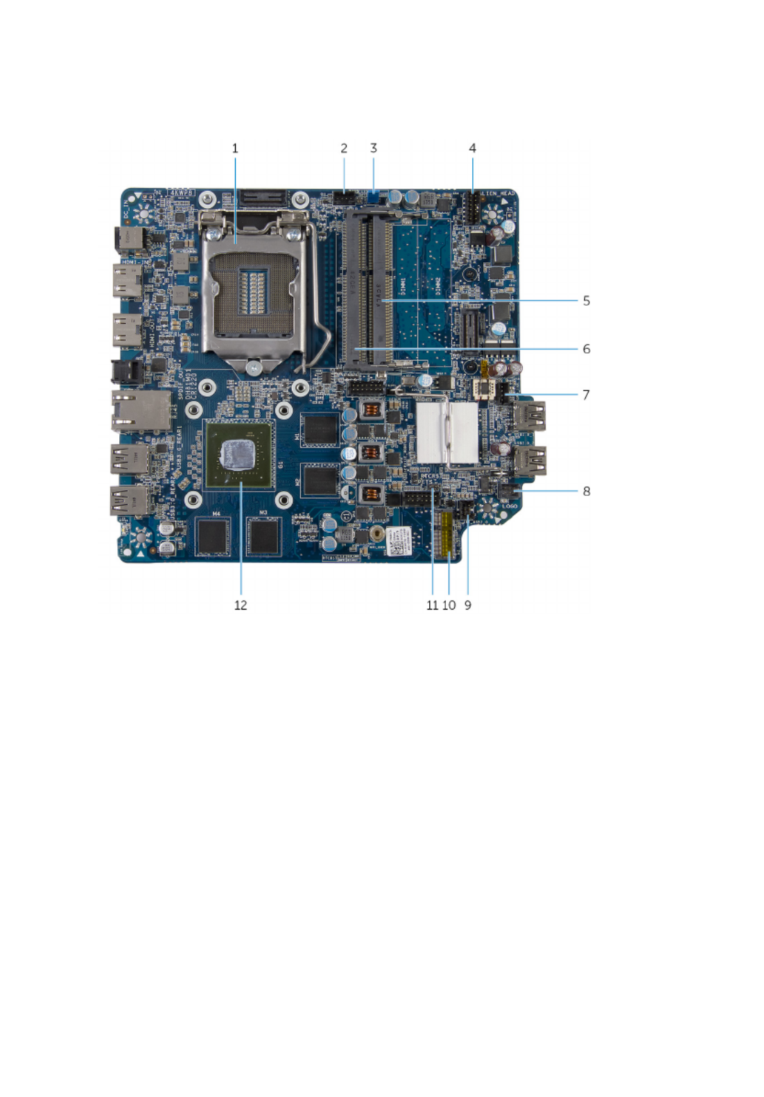
System-Board Components
1 processor socket 2 processor-fan cable connector
(CPU_FAN)
3 clear password jumper
(CLEAR_PASSWORD)
4 power-button connector
(ALIEN_HEAD)
5 memory-module slot (DIMM2) 6 memory-module slot (DIMM1)
7 video-card fan cable connector
(GPU_FAN)
8 front-panel light board cable
connector (LOGO)
9 USB-port cable connector
(INT_USB2)
10 wireless-card slot
11 clear CMOS jumper (RTCRST) 12 video card
13

Removing the Base Cover
WARNING: Before working inside your computer, read the
safety information that shipped with your computer and
follow the steps in Before Working Inside Your Computer.
After working inside your computer, follow the instructions
in . For more safety best After Working Inside Your Computer
practices, see the Regulatory Compliance home page at
dell.com/regulatory_compliance.
Procedure
1 Turn the computer over.
2 Remove the screws that secure the base cover to the top cover.
1 screws (4) 2 base cover
14

3 Using a plastic scribe, pry the base cover off the top cover.
1 plastic scribe 2 base cover
15

Replacing the Base Cover
WARNING: Before working inside your computer, read the
safety information that shipped with your computer and
follow the steps in Before Working Inside Your Computer.
After working inside your computer, follow the instructions
in . For more safety best After Working Inside Your Computer
practices, see the Regulatory Compliance home page at
dell.com/regulatory_compliance.
Procedure
1 Align the screw holes on the base cover with the screw holes on the top
cover and snap the base cover over the top cover.
2 Replace the screws that secure the base cover to the top cover.
16

Removing the Top Cover
WARNING: Before working inside your computer, read the
safety information that shipped with your computer and
follow the steps in Before Working Inside Your Computer.
After working inside your computer, follow the instructions
in . For more safety best After Working Inside Your Computer
practices, see the Regulatory Compliance home page at
dell.com/regulatory_compliance.
Prerequisites
Remove the .base cover
Procedure
1 Hold the chassis along with the top cover and then turn the computer
over.
17
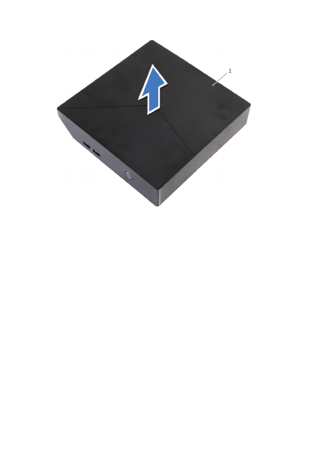
2 Lift the top cover off the chassis.
1 top cover
18

Replacing the Top Cover
WARNING: Before working inside your computer, read the
safety information that shipped with your computer and
follow the steps in Before Working Inside Your Computer.
After working inside your computer, follow the instructions
in . For more safety best After Working Inside Your Computer
practices, see the Regulatory Compliance home page at
dell.com/regulatory_compliance.
Procedure
1 Align the slots on the top cover with the ports on the chassis and place the
top cover on the chassis.
2 Hold the chassis along with the top cover and then turn the computer
over.
Post-requisites
Replace the .base cover
19

Removing the Hard Drive
WARNING: Before working inside your computer, read the
safety information that shipped with your computer and
follow the steps in Before Working Inside Your Computer.
After working inside your computer, follow the instructions
in . For more safety best After Working Inside Your Computer
practices, see the Regulatory Compliance home page at
dell.com/regulatory_compliance.
CAUTION: Hard drives are fragile. Exercise care when
handling the hard drive.
CAUTION: To avoid data loss, do not remove the hard drive
while the computer is in sleep or on state.
Prerequisites
Remove the .base cover
Procedure
1 Remove the screw that secures the hard-drive assembly to the chassis.
2 Slide the hard-drive assembly towards the back of the computer to
disconnect the hard drive from the system board.
20

3 Lift the hard-drive assembly off the chassis.
1 screw 2 hard-drive assembly
4 Remove the screws that secure the hard-drive bracket to the hard drive.
21

5 Lift the hard drive off the hard-drive bracket.
1 hard-drive bracket 2 hard drive
3 screws (4)
22

Replacing the Hard Drive
WARNING: Before working inside your computer, read the
safety information that shipped with your computer and
follow the steps in Before Working Inside Your Computer.
After working inside your computer, follow the instructions
in . For more safety best After Working Inside Your Computer
practices, see the Regulatory Compliance home page at
dell.com/regulatory_compliance.
CAUTION: Hard drives are fragile. Exercise care when
handling the hard drive.
Procedure
1 Align the screw holes on the hard drive with the screw holes on the hard-
drive bracket.
2 Replace the screws that secure the hard-drive bracket to the hard drive.
3 Align the slots on the hard-drive assembly with the tabs on the chassis.
4 Slide the hard-drive assembly towards the front of the computer to
connect the hard drive to the system board.
5 Replace the screw that secures the hard-drive assembly to the chassis.
Post-requisites
1 Replace the .top cover
2 Replace the .base cover
23

Removing the Bottom USB
Port
WARNING: Before working inside your computer, read the
safety information that shipped with your computer and
follow the steps in Before Working Inside Your Computer.
After working inside your computer, follow the instructions
in . For more safety best After Working Inside Your Computer
practices, see the Regulatory Compliance home page at
dell.com/regulatory_compliance.
Prerequisites
1 Remove the .base cover
2 Remove the .top cover
Procedure
1 Disconnect the USB-port cable from the system board.
24
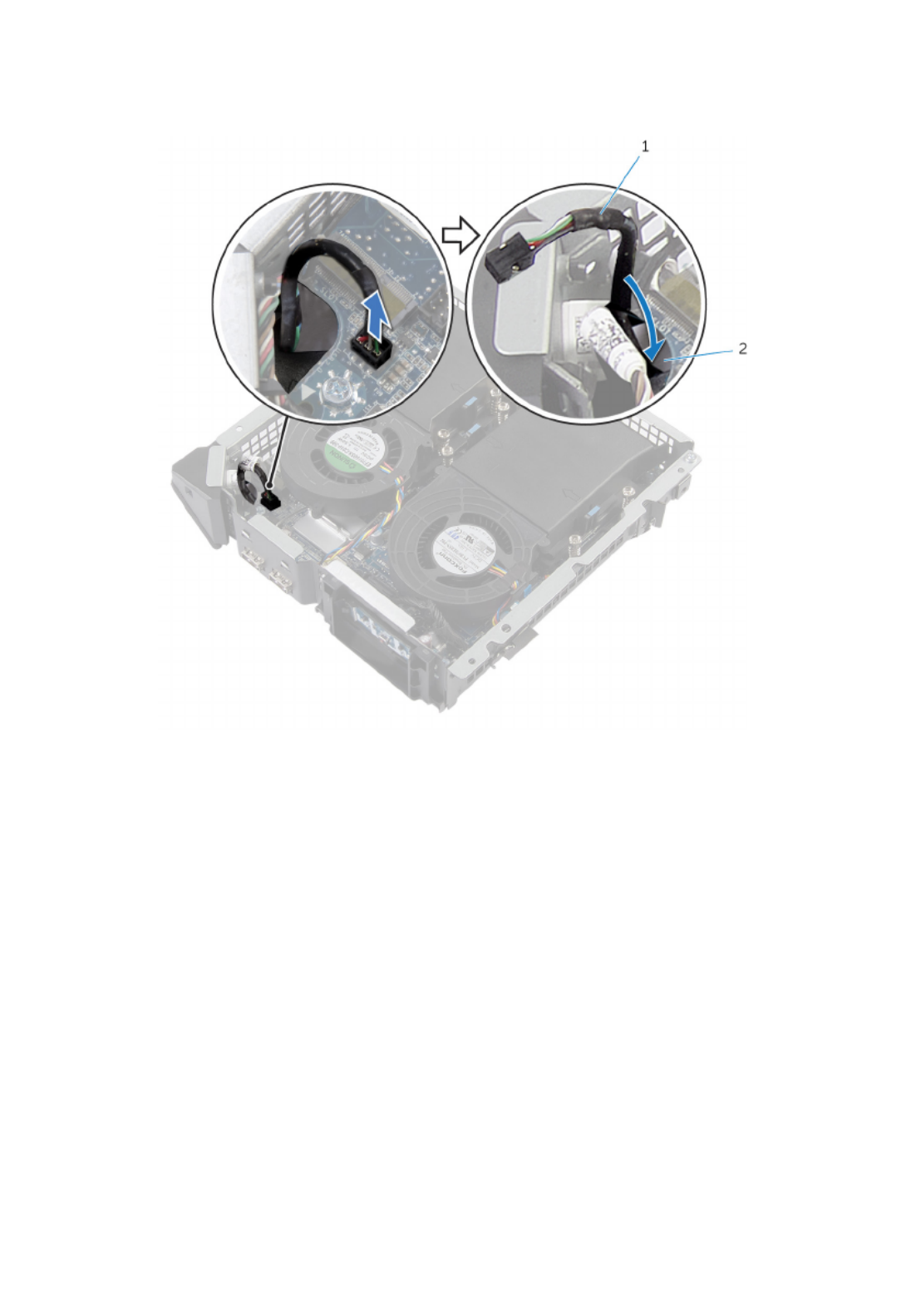
2 Push down the USB-port cable through the cable-routing hole on the
chassis.
1 USB-port cable 2 routing hole
3 Turn the computer over.
4 Remove the USB-port cable from the routing guides on the chassis.
5 Remove the screw that secures the USB-port bracket to the chassis.
6 Lift the USB-port bracket at an angle to release the tabs on the USB-port
bracket from the slots on the chassis.
25
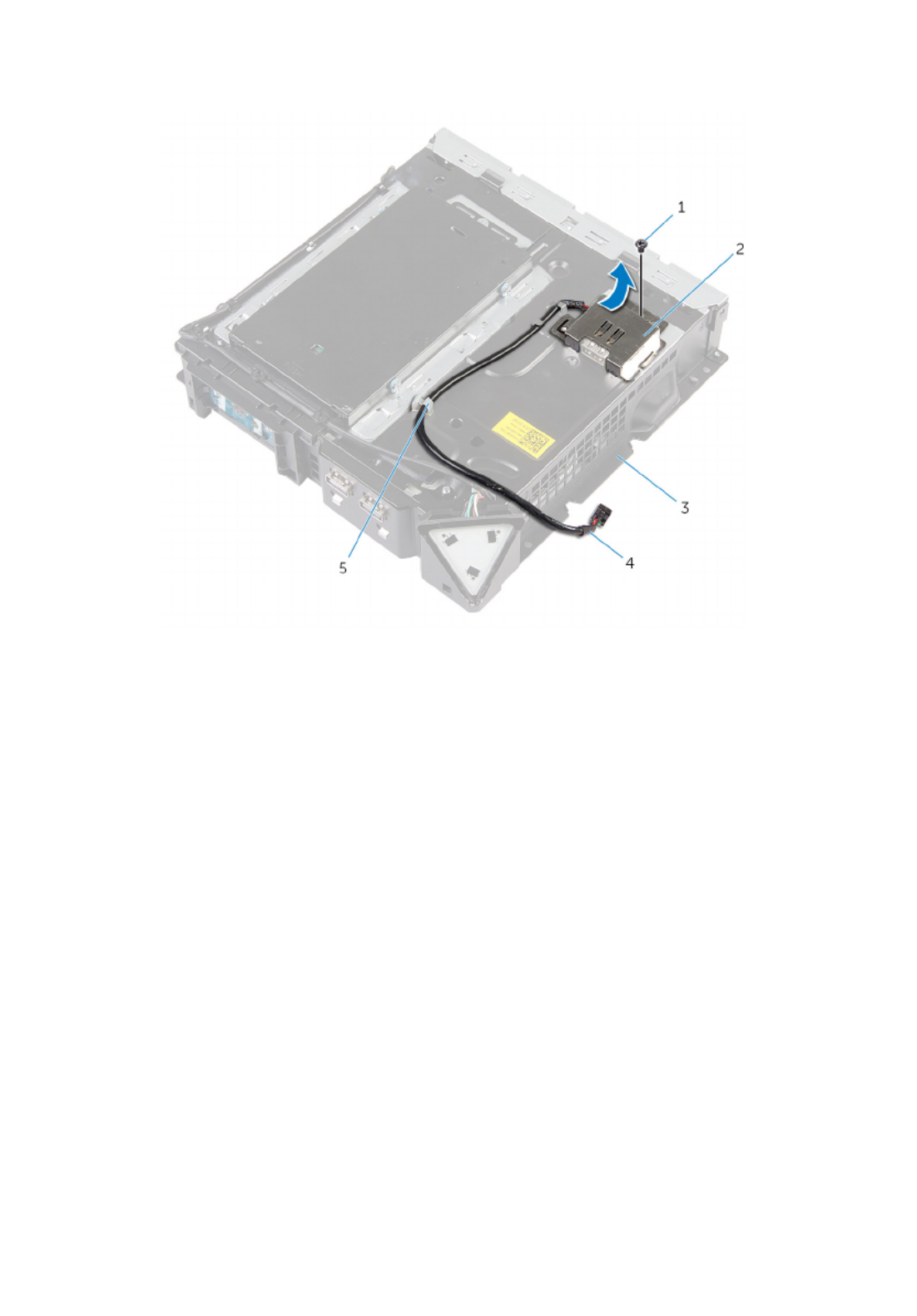
7 Lift the USB-port bracket off the chassis.
1 screw 2 USB-port bracket
3 chassis 4 USB-port cable
5 routing guides
8 Remove the screw that secures the USB port to the chassis.
26
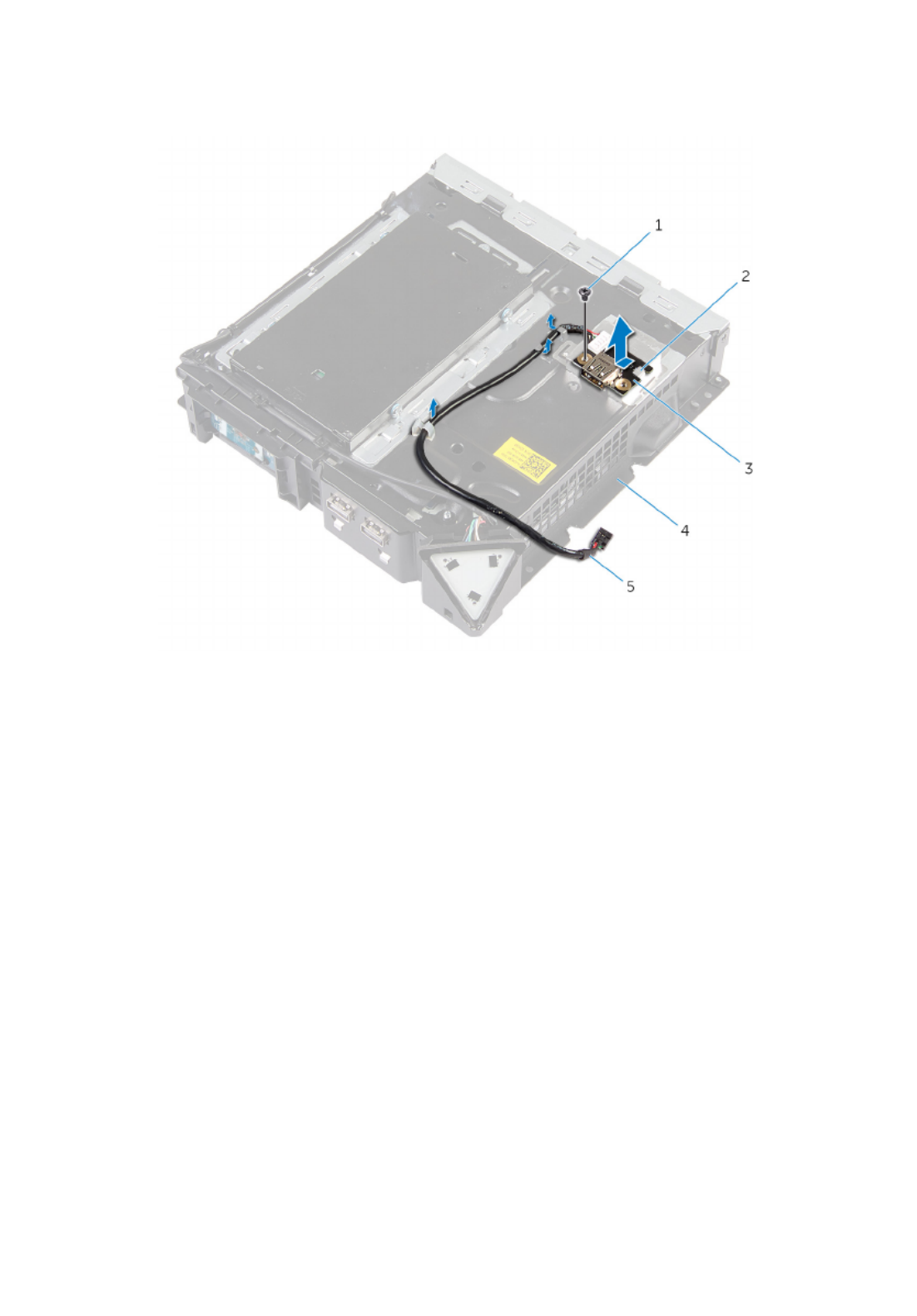
9 Slide and remove the USB port, along with the cable, from under the tab on
the chassis.
1 screw 2 tab
3 USB port 4 chassis
5 USB-port cable
27

Replacing the Bottom USB
Port
WARNING: Before working inside your computer, read the
safety information that shipped with your computer and
follow the steps in Before Working Inside Your Computer.
After working inside your computer, follow the instructions
in . For more safety best After Working Inside Your Computer
practices, see the Regulatory Compliance home page at
dell.com/regulatory_compliance.
Procedure
1 Slide the USB port under the tab on the chassis.
2 Replace the screw that secures the USB port to the chassis.
3 Align and slide the tabs on USB-port bracket in the slots on the chassis.
4 Replace the screw that secures the USB-port bracket to the chassis
5 Route the USB-port cable through the routing guides on the chassis and
slide the cable through the cable-routing hole on the chassis.
6 Turn the computer over.
7 Connect the USB-port cable to the system board.
Post-requisites
1 Replace the .top cover
2 Replace the .base cover
28

Removing the Power-Button
Board
WARNING: Before working inside your computer, read the
safety information that shipped with your computer and
follow the steps in Before Working Inside Your Computer.
After working inside your computer, follow the instructions
in . For more safety best After Working Inside Your Computer
practices, see the Regulatory Compliance home page at
dell.com/regulatory_compliance.
Prerequisites
1 Remove the .base cover
2 Remove the .top cover
Procedure
1 Disconnect the power-button board cable from the system board.
2 Turn the chassis over and remove the antenna cable from the routing
guides on the power-button module.
3 Press the tabs on the power-button module to release the module from
the front panel.
4 Release the tabs at the bottom of the power-button module from the slots
on the chassis.
29
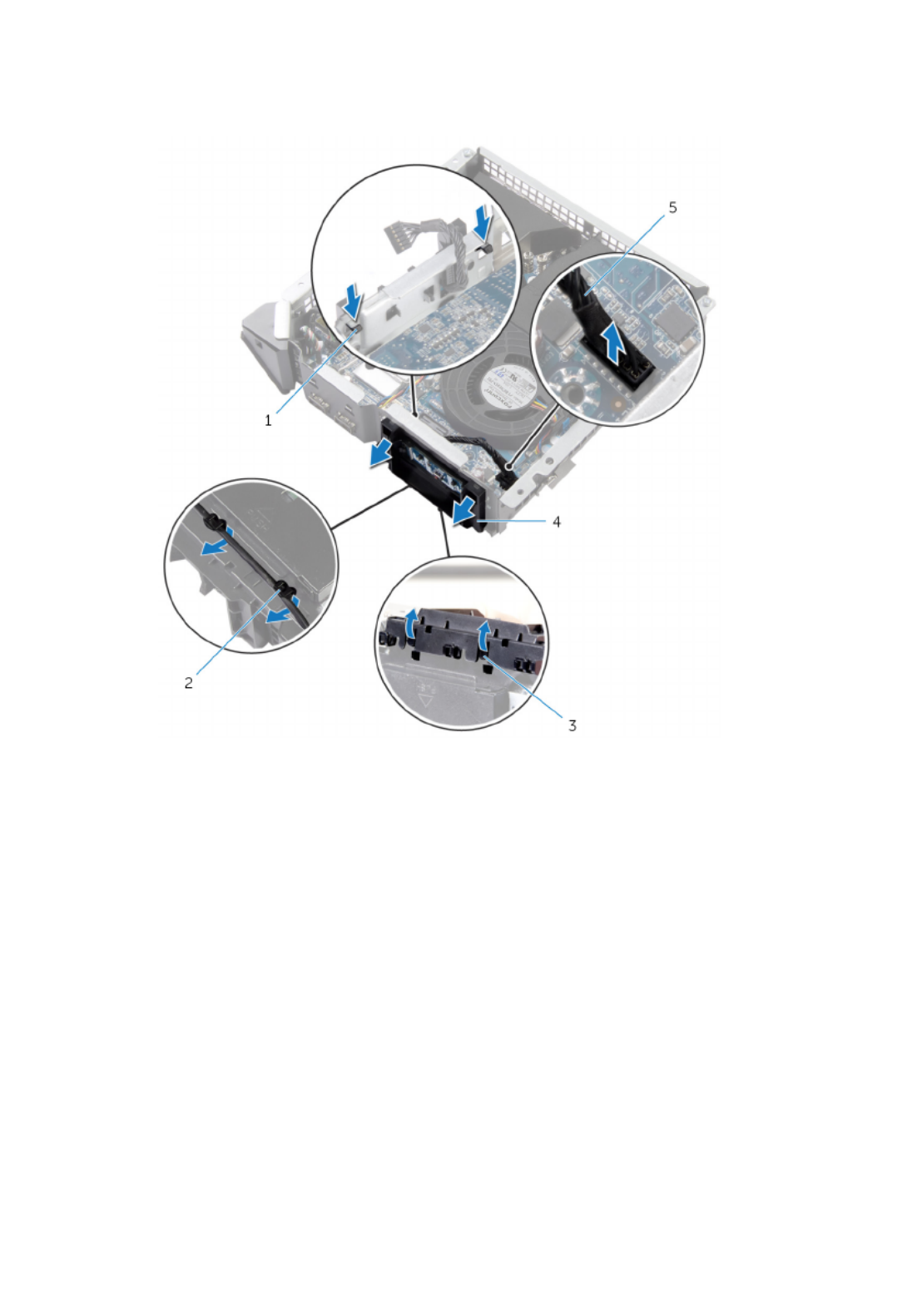
5 Remove the power-button module along with its cable through the slot on
the front panel.
1 tabs (2) 2 routing guides
3 tabs (2) 4 power-button module
5 power-button board cable
30

6 Push the tab that secures the power-button board to the power-button
board bracket.
1 tab 2 power-button board cable
3 power-button board 4 bracket
7 Lift and slide the power-button board to release it from the power-button
board bracket.
31

8 Remove the power-button board along with its cable off the power-button
board bracket.
1 power-button board cable 2 power-button board
3 bracket
32

Replacing the Power-Button
Board
WARNING: Before working inside your computer, read the
safety information that shipped with your computer and
follow the steps in Before Working Inside Your Computer.
After working inside your computer, follow the instructions
in . For more safety best After Working Inside Your Computer
practices, see the Regulatory Compliance home page at
dell.com/regulatory_compliance.
Procedure
1 Use the alignment posts on power-button board bracket to align the
power-button board into the slot on the power-button board bracket.
2 Snap the power-button board in place on the power-button board bracket.
3 Route the power-button board cable through the cable-routing hole on the
chassis.
4 Align and snap the power-button module into the slot on the front panel.
5 Connect the power-button board cable to the system board.
6 Turn over the chassis and route the antenna cable through the routing
guides on the power-button board module.
Post-requisites
1 Replace the .top cover
2 Replace the .base cover
33

Removing the Processor Fan
WARNING: Before working inside your computer, read the
safety information that shipped with your computer and
follow the steps in Before Working Inside Your Computer.
After working inside your computer, follow the instructions
in . For more safety best After Working Inside Your Computer
practices, see the Regulatory Compliance home page at
dell.com/regulatory_compliance.
Prerequisites
1 Remove the .base cover
2 Remove the .top cover
Procedure
1 Press the tabs and lift the processor fan off the system board.
1 processor fan 2 tabs (2)
34

2 Disconnect the processor-fan cable from the system board.
1 processor fan 2 processor-fan cable
35

Removing the Processor
Heat-Sink
WARNING: Before working inside your computer, read the
safety information that shipped with your computer and
follow the steps in Before Working Inside Your Computer.
After working inside your computer, follow the instructions
in . For more safety best After Working Inside Your Computer
practices, see the Regulatory Compliance home page at
dell.com/regulatory_compliance.
CAUTION: For maximum cooling of the processor, do not
touch the heat transfer areas on the heat sink. The oils in
your skin can reduce the heat transfer capability of the
thermal grease.
Prerequisites
1 Remove the .base cover
2 Remove the .top cover
3 Remove the .processor fan
Procedure
NOTE: The original thermal grease can be reused if the original processor
and heat sink are reinstalled together. If either the processor or the heat
sink is replaced, use the thermal grease provided in the kit to make sure
that thermal conductivity is achieved.
1 Loosen the captive screws that secure the processor heat sink to the
system board.
37

2 Lift the processor heat sink off system board.
1 processor heat sink 2 captive screws (4)
38

Replacing the Processor
Heat-Sink
WARNING: Before working inside your computer, read the
safety information that shipped with your computer and
follow the steps in Before Working Inside Your Computer.
After working inside your computer, follow the instructions
in . For more safety best After Working Inside Your Computer
practices, see the Regulatory Compliance home page at
dell.com/regulatory_compliance.
CAUTION: For maximum cooling of the processor, do not
touch the heat transfer areas on the heat sink. The oils in
your skin can reduce the heat transfer capability of the
thermal grease.
Procedure
CAUTION: Incorrect alignment of the heat sink may damage
the system board and processor.
NOTE: The original thermal grease can be reused if the original processor
and heat sink are reinstalled together. If either the processor or the heat
sink is replaced, use the thermal grease provided in the kit to make sure
that thermal conductivity is achieved.
1 Place the processor heat sink over the processor.
2 Align the captive screws on the processor heat sink with the screw holes
on the system board.
3 Tighten the captive screws that secure the processor heat sink to the
system board.
Post-requisites
1 Replace the .processor fan
2 Replace the .top cover
3 Replace the .base cover
39

Removing the Video-Card
Fan
WARNING: Before working inside your computer, read the
safety information that shipped with your computer and
follow the steps in Before Working Inside Your Computer.
After working inside your computer, follow the instructions
in . For more safety best After Working Inside Your Computer
practices, see the Regulatory Compliance home page at
dell.com/regulatory_compliance.
Prerequisites
1 Remove the .base cover
2 Remove the .top cover
Procedure
1 Disconnect the video-card fan cable from the system board.
40

Replacing the Video-Card
Fan
WARNING: Before working inside your computer, read the
safety information that shipped with your computer and
follow the steps in Before Working Inside Your Computer.
After working inside your computer, follow the instructions
in . For more safety best After Working Inside Your Computer
practices, see the Regulatory Compliance home page at
dell.com/regulatory_compliance.
Procedure
1 Align and snap the video-card fan over the video-card heat sink.
2 Connect the video-card fan cable to the system board.
Post-requisites
1 Replace the .top cover
2 Replace the .base cover
42

Procedure
NOTE: The original thermal grease can be reused if the original video card
and heat sink are reinstalled together. If either the video card or the heat
sink is replaced, use the thermal grease provided in the kit to make sure
that thermal conductivity is achieved.
1 In sequential order (indicated on the heat sink), loosen the captive screws
that secure the video-card heat sink to the system board.
1 video-card heat sink 2 captive screws (4)
2 Lift the video-card heat sink off the video-card heat sink.
44

Replacing the Video-Card
Heat Sink
WARNING: Before working inside your computer, read the
safety information that shipped with your computer and
follow the steps in Before Working Inside Your Computer.
After working inside your computer, follow the instructions
in . For more safety best After Working Inside Your Computer
practices, see the Regulatory Compliance home page at
dell.com/regulatory_compliance.
CAUTION: For maximum cooling of the processor, do not
touch the heat transfer areas on the heat sink. The oils in
your skin can reduce the heat transfer capability of the
thermal grease.
Procedure
CAUTION: Incorrect alignment of the heat sink may damage
the system board and video card.
NOTE: The original thermal grease can be reused if the original video card
and heat sink are reinstalled together. If either the video card or the heat
sink is replaced, use the thermal grease provided in the kit to make sure
that thermal conductivity is achieved.
1 Place the heat sink over the video card.
2 Align the captive screws on the video-card heat sink with the screw holes
on the system board.
3 In sequential order (indicated on the heat sink), tighten the captive screws
that secure the video-card heat sink to the system board.
Post-requisites
1 Replace the .video-card fan
2 Replace the .top cover
3 Replace the .base cover
45

Removing the Memory
Module(s)
WARNING: Before working inside your computer, read the
safety information that shipped with your computer and
follow the steps in Before Working Inside Your Computer.
After working inside your computer, follow the instructions
in . For more safety best After Working Inside Your Computer
practices, see the Regulatory Compliance home page at
dell.com/regulatory_compliance.
Prerequisites
1 Remove the .base cover
2 Remove the .top cover
3 Remove the .processor fan
Procedure
1 Using your fingertips, pry apart the securing clips on each end of the
memory-module slot until the memory module pops up.
46

2 Slide and remove the memory module from the memory-module slot.
1 memory-module slot 2 memory module
3 securing clips (2)
47

Replacing the Memory
Module(s)
WARNING: Before working inside your computer, read the
safety information that shipped with your computer and
follow the steps in Before Working Inside Your Computer.
After working inside your computer, follow the instructions
in . For more safety best After Working Inside Your Computer
practices, see the Regulatory Compliance home page at
dell.com/regulatory_compliance.
Procedure
1 Align the notch on the memory module with the tab on the memory-
module slot.
48

2 Slide the memory module into the memory-module slot and press the
memory module down until it clicks into place.
NOTE: If you do not hear the click, remove the memory module and
reinstall it.
1 memory module 2 notch
3 tab 4 memory-module slot
Post-requisites
1 Replace the .processor fan
2 Replace the .top cover
3 Replace the .base cover
49

Removing the Processor
WARNING: Before working inside your computer, read the
safety information that shipped with your computer and
follow the steps in Before Working Inside Your Computer.
After working inside your computer, follow the instructions
in . For more safety best After Working Inside Your Computer
practices, see the Regulatory Compliance home page at
dell.com/regulatory_compliance.
Prerequisites
1 Remove the .base cover
2 Remove the .top cover
3 Remove the .processor fan
4 Remove the .processor heat sink
Procedure
1 Press the release lever down and then push it away from the processor to
release it from the tab.
2 Extend the release lever completely and open the processor cover.
50
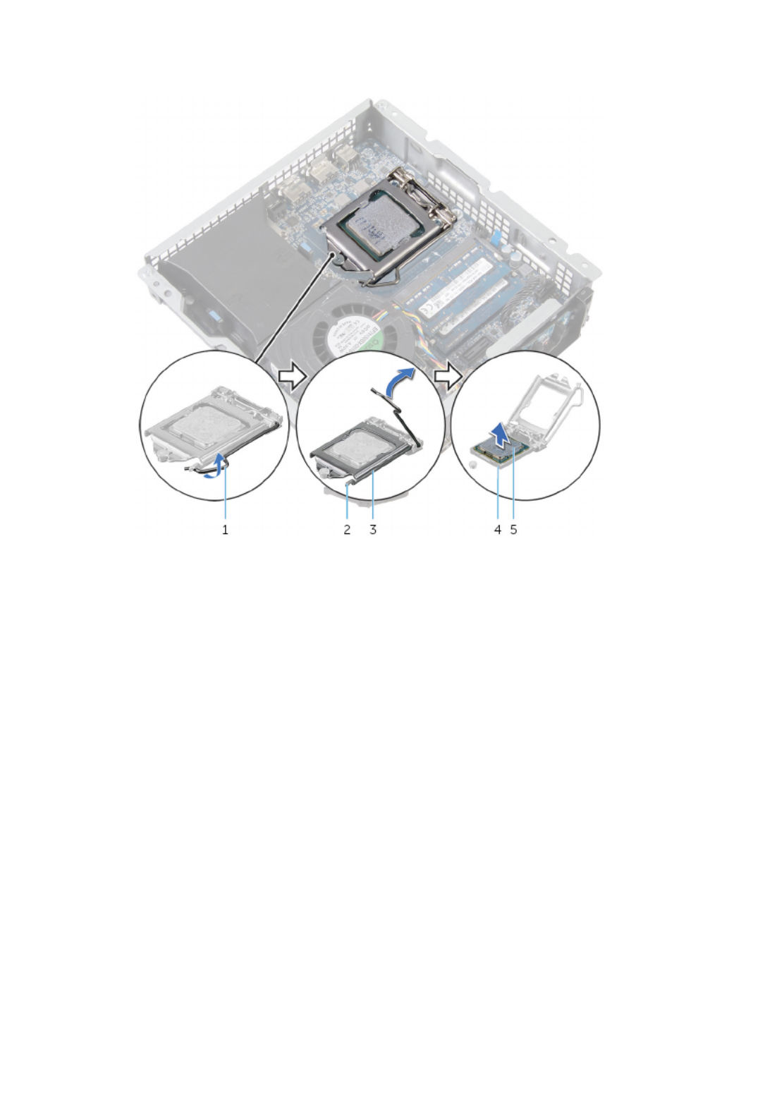
3 Lift the processor off the processor socket.
1 release lever 2 tab
3 processor cover 4 processor socket
5 processor
51

Replacing the Processor
WARNING: Before working inside your computer, read the
safety information that shipped with your computer and
follow the steps in Before Working Inside Your Computer.
After working inside your computer, follow the instructions
in . For more safety best After Working Inside Your Computer
practices, see the Regulatory Compliance home page at
dell.com/regulatory_compliance.
CAUTION: If either the processor or the heat sink is replaced,
use the thermal grease provided in the kit to make sure that
thermal conductivity is achieved.
Procedure
1 Make sure that the release lever on the processor socket is fully extended
and the processor cover is fully open.
CAUTION: Position the processor correctly in the
processor socket to avoid permanent damage to the
processor.
2 Align the notches on the processor with the tabs on the processor socket.
3 Align the pin-1 corner on the processor with the pin-1 corner on the
processor socket, and then place the processor in the processor socket.
CAUTION: Make sure that the processor-cover notch is
positioned underneath the alignment post.
4 When the processor is fully seated in the socket, close the processor cover.
52

5 Pivot the release lever down and place it under the tab on the processor
cover.
1 processor socket 2 processor
3 tab 4 processor cover
5 release lever
Post-requisites
1 Replace the .processor heat sink
2 Replace the .processor fan
3 Replace the .top cover
4 Replace the .base cover
53

Replacing the Front-Panel
Light Board
WARNING: Before working inside your computer, read the
safety information that shipped with your computer and
follow the steps in Before Working Inside Your Computer.
After working inside your computer, follow the instructions
in . For more safety best After Working Inside Your Computer
practices, see the Regulatory Compliance home page at
dell.com/regulatory_compliance.
Procedure
1 Align the tabs on the front-panel light module with the slots on the front
panel, and snap the front-panel light module onto the front panel.
2 Route the front-panel light board cable through the cable-routing hole on
the chassis.
3 Connect the front-panel light board cable to the system board.
Post-requisites
1 Replace the .video-card fan
2 Replace the .top cover
3 Replace the .base cover
57

Removing the Wireless Card
WARNING: Before working inside your computer, read the
safety information that shipped with your computer and
follow the steps in Before Working Inside Your Computer.
After working inside your computer, follow the instructions
in . For more safety best After Working Inside Your Computer
practices, see the Regulatory Compliance home page at
dell.com/regulatory_compliance.
Prerequisites
1 Remove the .base cover
2 Remove the .top cover
3 Remove the .video-card fan
Procedure
1 Remove the screw that secures the wireless card to the system board.
2 Lift the protective cover off the wireless card.
3 Disconnect the antenna cables from the wireless card.
58
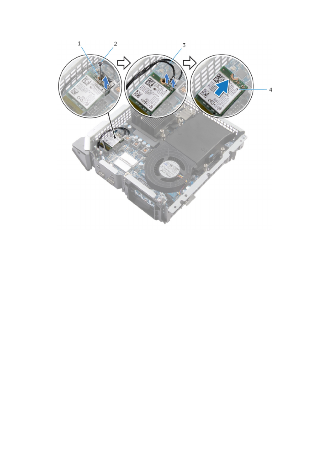
4 Slide and remove the wireless card out of the wireless-card slot.
1 protective cover 2 screw
3 antenna cables (2) 4 wireless card
59

Replacing the Wireless Card
WARNING: Before working inside your computer, read the
safety information that shipped with your computer and
follow the steps in Before Working Inside Your Computer.
After working inside your computer, follow the instructions
in . For more safety best After Working Inside Your Computer
practices, see the Regulatory Compliance home page at
dell.com/regulatory_compliance.
Procedure
CAUTION: To avoid damage to the wireless card, do not place
any cables under it.
1 Align the notch on the wireless card with the tab on the wireless-card slot.
2 Connect the antenna cables to the wireless card.
A label at the tip of the antenna cables indicates color scheme for the
wireless card supported by your computer.
Connectors on the wireless card Antenna-cable sticker
color
Auxiliary (1) White
Main (2) Black
3 Slide the wireless card at an angle into the wireless-card slot.
4 Press the other end of the wireless card down and replace the protective
cover on the wireless card.
5 Replace the screw that secures the wireless card to the system board.
Post-requisites
1 Replace the .video-card fan
2 Replace the .top cover
3 Replace the .base cover
60

Removing the Antenna
Modules
WARNING: Before working inside your computer, read the
safety information that shipped with your computer and
follow the steps in Before Working Inside Your Computer.
After working inside your computer, follow the instructions
in . For more safety best After Working Inside Your Computer
practices, see the Regulatory Compliance home page at
dell.com/regulatory_compliance.
Prerequisites
1 Remove the .base cover
2 Remove the .top cover
3 Remove the .video-card fan
4 Remove the .wireless card
61

Procedure
1 Slide the antenna cables through the cable-routing hole on the chassis.
1 antenna cables (2) 2 routing hole
2 Turn the computer over.
3 Remove the antenna cable from the routing guides on the power-button
module and chassis.
4 Remove the screws that secure the antenna modules to the chassis.
62

5 Using a plastic scribe, pry and slide the antenna modules, and release the
tabs on the antenna modules from the slots on the chassis.
1 routing guides 2 screws (2)
3 antenna modules (2) 4 antenna cable
6 Lift the antenna modules, along with the cable, off the chassis.
63

Replacing the Antenna
Modules
WARNING: Before working inside your computer, read the
safety information that shipped with your computer and
follow the steps in Before Working Inside Your Computer.
After working inside your computer, follow the instructions
in . For more safety best After Working Inside Your Computer
practices, see the Regulatory Compliance home page at
dell.com/regulatory_compliance.
Procedure
1 Align and slide the tabs on the antenna modules in the slots on the
chassis.
2 Align the screw holes on the antenna modules with the screws hole on the
chassis.
3 Replace the screws that secure the antenna modules to the chassis.
4 Route the antenna cable through the routing guides on the chassis and
power-button module.
5 Route the antenna cable through the cable-routing hole on the chassis.
Post-requisites
1 Replace the .wireless card
2 Replace the .video-card fan
3 Replace the .top cover
4 Replace the .base cover
64

Removing the System Board
WARNING: Before working inside your computer, read the
safety information that shipped with your computer and
follow the steps in Before Working Inside Your Computer.
After working inside your computer, follow the instructions
in . For more safety best After Working Inside Your Computer
practices, see the Regulatory Compliance home page at
dell.com/regulatory_compliance.
NOTE: Your computer’s Service Tag is stored in the system board. You
must enter the Service Tag in the BIOS setup program after you replace
the system board.
NOTE: Replacing the system board removes any changes you have made
to the BIOS using the BIOS setup program. You must make the desired
changes again after you replace the system board.
NOTE: Before disconnecting the cables from the system board, note the
location of the connectors so that you can reconnect them correctly after
you replace the system board.
Prerequisites
1 Remove the .base cover
2 Remove the .top cover
3 Remove the .hard drive
4 Remove the .processor fan
5 Remove the .processor heat sink
6 Remove the .processor
7 Remove the .video-card fan
8 Remove the .video-card heat sink
9 Remove the .memory modules
10 Remove the .wireless card
65

Procedure
1 Disconnect the USB-port cable, front-panel light board cable, and power-
button board cable from the system board.
For information on the location of connectors, see “System- Board
Components”.
1 power-button board cable 2 front-panel light board
cable
3 USB-port cable
2 Remove the screws that secure the back panel to the chassis.
66
Product specificaties
| Merk: | Alienware |
| Categorie: | Desktop |
| Model: | Alpha SMX2102C1AU |
| Kleur van het product: | Zwart |
| Gewicht: | 1810 g |
| Breedte: | 200 mm |
| Diepte: | 200 mm |
| Hoogte: | 55 mm |
| Gebruikershandleiding: | Ja |
| Bluetooth: | Ja |
| Frequentie van processor: | 2.9 GHz |
| Processorfamilie: | Intel® Core™ i3 |
| Processormodel: | i3-4130T |
| Aantal processorkernen: | 2 |
| Wi-Fi-standaarden: | 802.11a,Wi-Fi 5 (802.11ac),802.11b,802.11g,Wi-Fi 4 (802.11n) |
| Bluetooth-versie: | 4.0 |
| Inclusief besturingssysteem: | Windows 8.1 |
| Ondersteuning voor plaatsing: | Horizontaal |
| Ethernet LAN: | Ja |
| Meegeleverde kabels: | AC |
| Audiosysteem: | HD |
| Processor lithografie: | 22 nm |
| Inclusief AC-adapter: | Ja |
| Aantal USB 2.0-poorten: | 3 |
| Aantal HDMI-poorten: | 2 |
| DVI-poort: | Nee |
| Aantal Ethernet LAN (RJ-45)-poorten: | 1 |
| Netvoeding: | 130 W |
| Aansluiting voor netstroomadapter: | Ja |
| Intern geheugen: | 4 GB |
| Opslagmedia: | HDD |
| Intern geheugentype: | DDR3L-SDRAM |
| HDMI versie: | 1.4a |
| Wifi-standaard: | Wi-Fi 5 (802.11ac) |
| Ethernet LAN, data-overdrachtsnelheden: | 10,100,1000 Mbit/s |
| Bekabelingstechnologie: | 10/100/1000Base-T(X) |
| Temperatuur bij opslag: | -40 - 65 °C |
| Intel® Wireless Display (Intel® WiDi): | Ja |
| Aantal poorten USB 3.2 Gen 1 (3.1 Gen 1) Type A: | 2 |
| Processor socket: | LGA 1150 (Socket H3) |
| Systeembus: | 5 GT/s |
| Processor aantal threads: | 4 |
| PCI Express slots versie: | 3.0 |
| Processor operating modes: | 32-bit,64-bit |
| Processor cache: | 3 MB |
| Bus type: | DMI |
| PCI Express configuraties: | 2x8 |
| Thermal Design Power (TDP): | 35 W |
| Codenaam processor: | Haswell |
| Maximaal aantal PCI Express-lijnen: | 16 |
| Processor cache type: | Smart Cache |
| ECC ondersteund door processor: | Ja |
| Processorfabrikant: | Intel |
| Architectuur besturingssysteem: | 64-bit |
| Trial-software: | Microsoft Office |
| Maximum intern geheugen: | 16 GB |
| Totale opslagcapaciteit: | 500 GB |
| Soort optische drive: | Nee |
| Ingebouwde grafische adapter: | Ja |
| Familie ingebouwde grafische adapter: | Intel® HD Graphics |
| On-board graphics adapter model: | Intel® HD Graphics 4400 |
| Basisfrequentie ingebouwde grafische adapter: | 200 MHz |
| Graphics on-board -adapter dynamische frequentie (max): | 1150 MHz |
| On-board grafische adapter ID: | 0x41E |
| Maximaal geheugen ingebouwde grafische adapter: | 1.74 GB |
| On-board grafische adapter DirectX-versie: | 11.1 |
| Ondersteunde instructie sets: | AVX 2.0 |
| Intel® My WiFi Technology (Intel® MWT): | Nee |
| Intel® Smart Response Technology: | Nee |
| Intel® Hyper Threading Technology (Intel® HT Technology): | Ja |
| Intel® Turbo Boost Technology: | Nee |
| Intel® Quick Sync Video Technology: | Ja |
| Intel® InTru™ 3D Technology: | Ja |
| Intel® Clear Video HD Technology (Intel® CVT HD): | Ja |
| Intel® Insider™: | Nee |
| Intel® Flex Memory Access: | Nee |
| Intel® AES New Instructions (Intel® AES-NI): | Ja |
| Enhanced Intel SpeedStep Technology: | Ja |
| Execute Disable Bit: | Ja |
| Idle States: | Ja |
| Thermal Monitoring Technologies: | Ja |
| CPU configuratie (max): | 1 |
| Intel® Enhanced Halt State: | Ja |
| Intel® Clear Video Technology for Mobile Internet Devices (Intel® CVT for MID): | Nee |
| Intel® VT-x with Extended Page Tables (EPT): | Ja |
| Ingebouwde opties beschikbaar: | Nee |
| Graphics & IMC lithografie: | 22 nm |
| Intel® Small Business Advantage (Intel® SBA): | Nee |
| Intel® 64: | Ja |
| Intel® Virtualization Technology for Directed I/O (VT-d): | Nee |
| Intel® Clear Video-technologie: | Nee |
| Intel® Virtualization Technology (VT-x): | Ja |
| Verpakkingsgrootte processor: | 37.5 x 37.5 mm |
| Conflictvrije processor: | Ja |
| Intel® Identity Protection Technology (Intel® IPT): | Nee |
| ARK ID processor: | 77481 |
| Intel® Trusted Execution Technology: | Nee |
| Intel® TSX-NI: | Nee |
| Intel® Stable Image Platform Program (SIPP): | Nee |
| Versie Intel® Stable Image Platform Program (SIPP): | 0.00 |
| Versie Intel® TSX-NI: | 0.00 |
| Intel® Anti-Theft Technology (Intel® AT): | Nee |
| Intel® Rapid Start Technology: | Nee |
| Intel® Smart Connect Technology: | Nee |
| Toetsenbord inbegrepen: | Nee |
| Luchtvochtigheid bij opslag: | 0 - 95 procent |
| Inclusief muis: | Nee |
| Type behuizing: | Desktop |
| Maximaal intern geheugen ondersteund door processor: | 32 GB |
| Geheugentypen ondersteund door processor: | DDR3-SDRAM |
| Klokgeheugen-snelheden ondersteund door processor: | 1333,1600 MHz |
| Kloksnelheid geheugen: | 1600 MHz |
| Geheugenlayout: | 1 x 4 GB |
| Geheugenslots: | 2x SO-DIMM |
| Aantal displays ondersteund (door on-board grafische adapter): | 3 |
| Aantal geïnstalleerde processoren: | 1 |
| Geheugenbandbreedte ondersteund door de processor ( max): | 25.6 GB/s |
| Aantal storage drives geïnstalleerd: | 1 |
| Chipset moederbord: | Intel® H81 |
| Inclusief monitor: | Nee |
| Schaalbaarheid: | 1S |
| Thermal solution specificatie: | PCG 2013A |
| Hoogte, in bedrijf: | -15.24 - 3048 m |
| Hoogte bij opslag: | -15.24 - 10668 m |
| Specifiek grafisch geheugentype: | GDDR5 |
| Grafische geheugen: | 2048 GB |
| Aantal discrete graphics adapters: | 1 |
| Het aantal geïnstalleerde HDD's: | 1 |
| HDD capaciteit: | 500 GB |
| HDD interface: | SATA III |
| HDD rotatiesnelheid: | 5400 RPM |
| FSB Parity: | Nee |
| Front-side bus processor: | - MHz |
| Tcase: | 72 °C |
| Intel® Demand Based Switching: | Nee |
| Processorserie: | Intel Core i3-4100 Desktop series |
| S/PDIF-uitgang: | Ja |
| Intel® Dual Display Capable Technology: | Nee |
| Intel® FDI Technology: | Nee |
| Intel® Rapid Storage Technology: | Nee |
| Intel® Fast Memory Access: | Nee |
| Intel® Small Business Advantage (SBA)-versie: | 1.00 |
| Geheugen kanaal: | Dual-channel |
| HDD omvang: | 2.5 " |
| Intel® Virtualization Technology (Intel® VT): | VT-x |
| Voeding, voltage ingang: | 100 - 240 V |
| Wifi: | Ja |
| Bedrijfstemperatuur (T-T): | 5 - 35 °C |
| Relatieve vochtigheid in bedrijf (V-V): | 10 - 90 procent |
| Type product: | Mini PC |
| Ingangsfrequentie voeding: | 50 - 60 Hz |
| Waterkoelingsysteem: | Nee |
| Processorgeneratie: | Vierde generatie Intel® Core™ i3 |
| Taal besturingssysteem: | Engels |
Heb je hulp nodig?
Als je hulp nodig hebt met Alienware Alpha SMX2102C1AU stel dan hieronder een vraag en andere gebruikers zullen je antwoorden
Handleiding Desktop Alienware

29 November 2023
21 Juni 2023
20 Juni 2023
10 Juni 2023
10 Juni 2023
10 Juni 2023
8 Juni 2023
8 Juni 2023
5 Juni 2023
30 Mei 2023
Handleiding Desktop
- Desktop HP
- Desktop Sony
- Desktop Samsung
- Desktop LG
- Desktop Asus
- Desktop Medion
- Desktop Toshiba
- Desktop VTech
- Desktop Acer
- Desktop AOC
- Desktop AOpen
- Desktop Apple
- Desktop Asrock
- Desktop Axis
- Desktop BenQ
- Desktop Dell
- Desktop Emachines
- Desktop Faytech
- Desktop Fujitsu
- Desktop Gigabyte
- Desktop Haier
- Desktop Ibm
- Desktop InFocus
- Desktop Kobo
- Desktop Kogan
- Desktop Lenovo
- Desktop Maxdata
- Desktop Microsoft
- Desktop Mio
- Desktop MP
- Desktop MSI
- Desktop Nec
- Desktop Packard Bell
- Desktop Peaq
- Desktop Razer
- Desktop Seagate
- Desktop Sharkoon
- Desktop Sharp
- Desktop Targa
- Desktop Trekstor
- Desktop Viewsonic
- Desktop Wehkamp
- Desktop Woood
- Desktop ZTE
- Desktop Jysk
- Desktop ONYX
- Desktop Optoma
- Desktop Parisot
- Desktop Intel
- Desktop BDI
- Desktop Tripp Lite
- Desktop LC-Power
- Desktop Zoostorm
- Desktop ZOTAC
- Desktop Planar
- Desktop Supermicro
- Desktop ELO
- Desktop Shuttle
- Desktop VXL
- Desktop ECS
- Desktop Vorago
- Desktop Promethean
- Desktop Foxconn
- Desktop Advantech
- Desktop Moxa
- Desktop Kramer
- Desktop Elitegroup
- Desktop Smart Things
- Desktop System76
- Desktop Bestar
- Desktop Pelco
- Desktop Cybernet
- Desktop Altra
- Desktop Dell Wyse
- Desktop NComputing
- Desktop MvixUSA
- Desktop AIS
- Desktop Wyse
Nieuwste handleidingen voor Desktop

28 Maart 2025
27 Maart 2025

25 Februari 2025
25 Februari 2025
25 Februari 2025
24 Februari 2025

10 Februari 2025

30 Januari 2025

27 Januari 2025

10 Januari 2025