Vauxhall Grandland X (2019) Handleiding
Lees hieronder de 📖 handleiding in het Nederlandse voor Vauxhall Grandland X (2019) (283 pagina's) in de categorie Auto. Deze handleiding was nuttig voor 30 personen en werd door 2 gebruikers gemiddeld met 4.5 sterren beoordeeld
Pagina 1/283


Introduction .................................... 2
In brief ............................................ 6
Keys, doors and windows ............ 20
Seats, restraints ........................... 44
Storage ........................................ 68
Instruments and controls ............. 78
Lighting ...................................... 112
Climate control ........................... 122
Driving and operating ................. 133
Vehicle care ............................... 210
Service and maintenance .......... 250
Technical data ........................... 256
Customer information ................ 268
Index .......................................... 276
Contents

2 Introduction
Introduction

Introduction 3
Vehicle specific data
Please enter your vehicle's data on
the previous page to keep it easily
accessible.
Please refer to the sections "Service
and maintenance", "Technical data",
the vehicle's identification plate and
national registration documents.
Introduction
Your vehicle is a designed
combination of advanced technology,
safety, environmental friendliness
and economy.
This Owner's Manual provides you
with all the necessary information to
enable you to drive your vehicle
safely and efficiently.
Make sure your passengers are
aware of the possible risk of accident
and injury which may result from
improper use of the vehicle.
You must always comply with the
specific laws and regulations of the
country that you are in. These laws
may differ from the information in this
Owner's Manual.
Disregarding the description given in
this manual may affect your warranty.
When this Owner's Manual refers to a
workshop visit, we recommend your
Vauxhall Authorised Repairer.
All Vauxhall Authorised Repairers
provide first-class service at
reasonable prices. Experienced
mechanics trained by Vauxhall work
according to specific Vauxhall
instructions.
The customer literature pack should
always be kept ready to hand in the
vehicle.
Using this manual
● This manual describes all options
and features available for this
model. Certain descriptions,
including those for display and
menu functions, may not apply to
your vehicle due to model
variant, country specifications,
special equipment or
accessories.
● The "In brief" section will give you
an initial overview.
● The table of contents at the
beginning of this manual and
within each section shows where
the information is located.
● The index will enable you to
search for specific information.
● This Owner's Manual depicts left-
hand drive vehicles. Operation is
similar for right-hand drive
vehicles.
● The Owner's Manual uses the
engine identifier code. The
corresponding sales designation
and engineering code can be
found in the section "Technical
data".
● Directional data, e.g. left or right,
or front or back, always relate to
the direction of travel.
● Displays may not support your
specific language.
● Display messages and interior
labelling are written in bold
letters.

4 Introduction
Danger, Warnings and
Cautions
9Danger
Text marked 9 Danger provides
information on risk of fatal injury.
Disregarding this information may
endanger life.
9Warning
Text marked 9 Warning provides
information on risk of accident or
injury. Disregarding this
information may lead to injury.
Caution
Text marked Caution provides
information on possible damage to
the vehicle. Disregarding this
information may lead to vehicle
damage.
Symbols
Page references are indicated with 3.
3 means "see page".
Page references and index entries
refer to the indented headings given
in the section table of content.
Thank you for choosing a Vauxhall.
We wish you many hours of
pleasurable driving.
Your Vauxhall Team

Introduction 5

6 In brief
In brief
Initial drive information
Vehicle unlocking
Press c to unlock the vehicle. Open
the doors by pulling the handles.
Press P to unlock the tailgate only.
Tailgate
After unlocking, press the tailgate
button and open the tailgate.
Radio remote control 3 21.
Central locking system 3 23.
Electronic key system 3 22.
Load compartment 3 29.

In brief 7
Seat adjustment
Longitudinal adjustment
Pull handle, slide seat, release
handle. Try to move the seat back and
forth to ensure that the seat is locked
in place.
Seat position 3 45.
Manual seat adjustment 3 46.
Backrests inclination
Turn handwheel. Do not lean on
backrest when adjusting.
Seat position 3 45.
Manual seat adjustment 3 46.
Seat height
Lever pumping motion
up : seat higher
down : seat lower
Seat position 3 45.
Manual seat adjustment 3 46.

8 In brief
Seat inclination
Press switch
top : front end higher
bottom : front end lower
Seat position 3 45.
Manual seat adjustment 3 46.
Head restraint adjustment
Press release button, adjust height,
engage.
Head restraints 3 44.
Seat belt
Pull out the seat belt and fasten in
seat belt buckle. The seat belt must
not be twisted and must fit close
against the body. The backrest must
not be tilted back too far (maximum
approx. 25°).
To unfasten seat belt, press red
button on seat belt buckle.
Seat position 3 45.
Seat belts 3 51.
Airbag system 3 54.

In brief 9
Mirror adjustment
Interior mirror
To adjust the mirror, move the mirror
housing in the desired direction.
Manual anti-dazzle interior mirror
3 38.
Automatic anti-dazzle interior mirror
3 38.
Exterior mirrors
Select the relevant exterior mirror by
pushing the mirror button to the left or
right. Adjust respective mirror by the
four-way control.
Convex mirrors 3 36.
Electric adjustment 3 36.
Folding mirrors 3 37.
Heated mirrors 3 37.
Steering wheel adjustment
Unlock lever, adjust steering wheel,
then engage lever and ensure it is
fully locked. Do not adjust steering
wheel unless vehicle is stationary and
steering wheel lock has been
released.
Seat position 3 45.
Ignition positions 3 134.

10 In brief
Instrument panel overview

In brief 11
1Power windows ..................... 39
2Exterior mirrors ..................... 36
3Side air vents ...................... 131
4Turn lights, headlight
flash, low / high beam,
high beam assist ................. 117
Exit lighting ......................... 121
Parking lights ...................... 119
Buttons for Driver
Information Centre .............. 100
5Cruise control ..................... 159
Speed limiter ....................... 162
Heated steering wheel .......... 80
6Instruments .......................... 89
Driver Information Centre .... 100
7Infotainment controls
8Windscreen wiper and
washer, rear wiper and
washer ................................. 80
9Power button ....................... 135
10 Air vents ............................. 131
11 Hazard warning flashers .... 117
12 Info Display ........................ 102
13 Light sensor ........................ 113
Sun sensor .......................... 126
14 Central locking system .......... 23
15 Glovebox .............................. 68
16 Controls for Info Display
operation ............................. 102
17 Climate control system ........ 123
18 USB charging port ................ 84
19 Power outlet .......................... 84
20 Parking assist, advanced
parking assist ..................... 176
Lane departure warning ..... 190
Eco button for stop-start
system ................................. 138
Electronic Stability Control
and Traction Control ........... 156
Sport mode ......................... 158
21 Manual transmission .......... 150
Automatic transmission ...... 147
22 Electric parking brake ......... 153
23 Selective ride control .......... 157
24 Ignition switch ..................... 134
25 Steering wheel adjustment ..79
26 Horn ..................................... 80
27 Storage ................................. 68
28 Bonnet release lever .......... 213
29 Light switch ........................ 112
Headlight range
adjustment ......................... 114
Front / rear fog lights .......... 118
Instrument illumination ....... 119
12 In brief
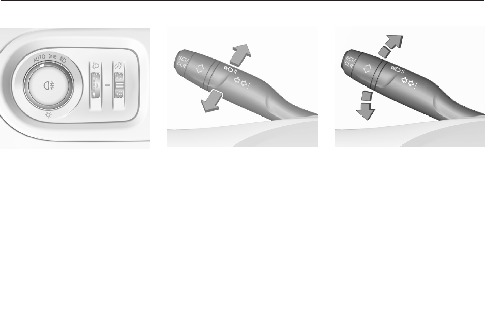
Exterior lighting
AUTO : automatic light control
switches automatically
between daytime running
light and headlight
8: sidelights
9: headlights
Automatic light control 3 113.
Front fog lights 3 118.
Rear fog light 3 118.
Headlight flash and high beam
pull : headlight flash
push : high beam
High beam 3 113.
High beam assist 3 114.
Headlight flash 3 113.
LED headlights 3 114.
Turn lights
up : right turn light
down : left turn light
Turn lights 3 117.
Parking lights 3 119.

In brief 13
Hazard warning flashers
Operated by pressing ¨.
Hazard warning flashers 3 117.
Horn
Press j.
Washer and wiper systems
Windscreen wiper
HI : fast
LO : slow
INT : interval wiping
or
AUTO : automatic wiping with rain
sensor
OFF : off
For single wipe when the wiper is off,
press down to position 1x.
Windscreen wiper 3 80.

14 In brief
Windscreen washer
Pull.
Windscreen washer system 3 80.
Washer fluid 3 215.
Wiper blade replacement 3 218.
Rear window wiper
OFF : off
INT : intermittent operation
ON : continuous operation
Rear window washer
Push.
Washer fluid is sprayed on the rear
window and the wiper wipes a few
times.
Rear window wiper / washer 3 82.

In brief 15
Climate control
Heated rear window
Heating and ventilation system, air
conditioning system
The heating is operated by pressing
b.
Electronic climate control system
The heating is operated by pressing
b.
Heated rear window 3 40.
Heated exterior mirrors
Pressing b also activates the heated
exterior mirrors.
Heated exterior mirrors 3 37.
Demisting and defrosting the
windows
Heating and ventilation system, air
conditioning system
● press à, the air distribution is
directed towards the windscreen
● set temperature controller £ to
warmest level
● switch on air conditioning A/C, if
required
● set fan speed Z to highest level
● switch on heated rear window b

16 In brief
● switch on heated windscreen ,
● open side air vents as required
and direct them towards the door
windows
Heating and ventilation system
3 122.
Air conditioning system 3 123.
Heated windscreen 3 41.
Electronic climate control system
● press à, the LED in the button
illuminates to indicate activation
● temperature and air distribution
are set automatically and the fan
runs at high speed
● switch on air conditioning by
pressing A/C, if required
● switch on heated rear window b
● switch on heated windscreen ,
● to return to previous mode, press
à again
● to return to automatic mode,
press AUTO
Electronic climate control system
3 126.

In brief 17
Transmission
Manual transmission
To engage reverse on 6-speed
transmission, depress the clutch
pedal, pull the ring under the selector
lever and move the selector lever
quite to the left and front.
Manual transmission 3 150.
Automatic transmission
P: park position
R: reverse
N: neutral mode
D: automatic mode
M: manual mode
<: upshift
]: downshift
Automatic transmission 3 147.
Starting off
Check before starting off
● tyre pressure 3 231 and
condition 3 266
● engine oil level and fluid levels
3 214
● all windows, mirrors, exterior
lighting and number plates are
free from dirt, snow and ice and
are operational
● proper position of mirrors 3 36,
seats 3 45 and seat belts
3 52
● brake function at low speed,
particularly if the brakes are wet

18 In brief
Starting the engine
Ignition switch
● turn key to position 1
● move the steering wheel slightly
to release the steering wheel lock
● manual transmission: operate
clutch and brake pedal
automatic transmission: operate
brake pedal and move selector
lever to P or N
● do not operate accelerator pedal
● Diesel engine: wait until control
indicator ! for preheating
extinguishes
● turn key to position 2 and release
after engine has been started
Starting the engine 3 136.
Start power button
● manual transmission: operate
clutch and brake pedal
automatic transmission: operate
brake pedal and move selector
lever to P or N
● do not operate accelerator pedal
● press Start/Stop button
● release button after starting
procedure begins

In brief 19
Stop-start system
If the vehicle is at a low speed or at a
standstill and certain conditions are
fulfilled, an Autostop is activated.
An Autostop is indicated by control
indicator D.
Manual transmission: to restart the
engine, depress the clutch pedal
again. Control indicator D
extinguishes.
Automatic transmission: to restart the
engine, release the brake pedal.
Control indicator D extinguishes.
Stop-start system 3 138.
Parking
9Warning
● Do not park the vehicle on an
easily ignitable surface. The
high temperature of the
exhaust system could ignite the
surface.
● Always apply the parking
brake.
● If the vehicle is on a level
surface or uphill slope, engage
first gear or set the selector
lever to position P. On an uphill
slope, turn the front wheels
away from the kerb.
If the vehicle is on a downhill
slope, engage reverse gear or
set the selector lever to position
P. Turn the front wheels
towards the kerb.
● Close the windows.
● Switch off the engine.
● Remove the ignition key from
the ignition switch or switch off
ignition on vehicles with power
button. Turn the steering wheel
until the steering wheel lock is
felt to engage.
●Lock the vehicle with e on the
radio remote control.
Activate the anti-theft alarm
system 3 34.
● The engine cooling fans may run
after the engine has been
switched off 3 213.
Caution
After running at high engine
speeds or with high engine loads,
operate the engine briefly at a low
load or run in neutral for
approx. 30 seconds before
switching off, in order to protect
the turbocharger.
Keys, locks 3 20.
Laying-up the vehicle for a long
period of time 3 212.

20 Keys, doors and windows
Keys, doors and
windows
Keys, locks ................................... 20
Keys .......................................... 20
Radio remote control ................. 21
Electronic key system ................ 22
Central locking system .............. 23
Automatic locking ...................... 27
Child locks ................................. 28
Doors ........................................... 29
Load compartment .................... 29
Vehicle security ............................ 34
Anti-theft locking system ........... 34
Anti-theft alarm system .............. 34
Immobiliser ................................ 36
Exterior mirrors ............................ 36
Convex shape ........................... 36
Electric adjustment .................... 36
Folding mirrors .......................... 37
Heated mirrors ........................... 37
Interior mirrors ............................. 38
Manual anti-dazzle .................... 38
Automatic anti-dazzle ................ 38
Windows ...................................... 38
Windscreen ............................... 38
Power windows ......................... 39
Heated rear window .................. 40
Heated windscreen .................... 41
Sun visors .................................. 42
Roller blinds ............................... 42
Roof ............................................. 42
Glass panel ............................... 42
Keys, locks
Keys
Caution
Do not attach heavy or bulky items
to the ignition key.
Replacement keys
The key number is specified on a
detachable tag.
The key number must be quoted
when ordering replacement keys as it
is a component of the immobiliser
system.
Locks 3 246.
Central locking 3 23.
Starting the engine 3 136.
Radio remote control 3 21.
Electronic key 3 22.
The code number of the adapter for
the locking wheel nuts is specified on
a card. It must be quoted when
ordering a replacement adapter.
Wheel changing 3 237.

Keys, doors and windows 21
Key with foldaway key section
Press button to extend. To fold the
key, first press the button.
Lock cylinders
Designed to free-wheel if they are
forcefully rotated without the correct
key or if the correct key is not fully
inserted. To reset, turn cylinder with
the correct key until its slot is vertical,
remove key then re-insert it. If the
cylinder still free-wheels, turn the key
through 180° and repeat operation.
Radio remote control
Enables operation of the following
functions via the use of the remote
control buttons:
● central locking system 3 23
● anti-theft locking system 3 34
● anti-theft alarm system 3 34
● tailgate unlocking and opening
● power windows 3 39
● mirrors folding 3 37
The remote control has a range of up
to 100 m, but may also be much less
due to external influences. The
hazard warning flashers confirm
operation.
Handle with care, protect from
moisture and high temperatures and
avoid unnecessary operation.
Replacing battery in radio remote
control
Replace the battery as soon as the
range reduces.
Batteries do not belong in household
waste. They must be disposed of at
an appropriate recycling collection
point.

22 Keys, doors and windows
1. Remove the back cover from the
remote control.
2. Extract the flat battery from its
location.
3. Replace battery with a battery of
the same type. Pay attention to
the installation position.
4. Clip the back cover in place.
Fault
If the central locking system cannot
be operated with the radio remote
control, the cause may be one of the
following:
● Fault in radio remote control.
● Electronic key is out of reception
range.
● The battery voltage is too low.
● Overload of the central locking
system by operating at frequent
intervals, the power supply is
interrupted for a short time.
● Interference from higher-power
radio waves from other sources.
Manual unlocking 3 23.
Electronic key system
Enables a keyless operation of the
following functions:
● central locking system 3 23
● power tailgate 3 29
● ignition switching on and starting
the engine 3 136
The electronic key simply needs to be
on the driver's person.
Additionally, the electronic key
includes the functionality of the radio
remote control 3 21.
Handle with care, protect from
moisture and high temperatures and
avoid unnecessary operation.

Keys, doors and windows 23
Notice
To save battery power, the keyless
functions are set to stand-by after 21
days of non-use. To reactivate the
functions, press a button on the
electronic key.
Replacing battery in electronic
key
Replace the battery as soon as the
system no longer operates properly
or the range is reduced. The need for
battery replacement is indicated by a
message in the Driver Information
Centre 3 106.
Batteries do not belong in household
waste. They must be disposed of at
an appropriate recycling collection
point.
1. Remove the cover.
2. Extract the flat battery from its
location.
3. Replace battery with a battery of
the same type. Pay attention to
the installation position.
4. Clip the cover in place.
Fault
If the central locking cannot be
operated or the engine cannot be
started, the cause may be one of the
following:
● Fault in electronic key.
● Electronic key is out of reception
range.
● The battery voltage is too low.
● Overload of the central locking
system by operating at frequent
intervals, the power supply is
interrupted for a short time.
● Interference from higher-power
radio waves from other sources.
To rectify the cause of the fault,
change the position of the electronic
key.
Manual unlocking 3 23.
Central locking system
Unlocks and locks doors, load
compartment and fuel filler flap.
A pull on an interior door handle
unlocks the respective door. Pulling
the handle once more opens the door.
Notice
In the event of an accident in which
airbags or belt pretensioners are
deployed, the vehicle is
automatically unlocked.
Notice
A short time after unlocking with the
remote control the doors are locked
automatically if no door has been

24 Keys, doors and windows
opened. A precondition is that the
setting is activated in the vehicle
personalisation 3 107.
Remote control operation
Unlocking
Press O.
Unlocking mode can be set in the
vehicle personalisation menu in the
Info Display. Two settings are
selectable:
● All doors, load compartment and
fuel filler flap will be unlocked by
pressing O once.
● Only the driver's door and fuel
filler flap will be unlocked by
pressing O once. To unlock all
doors, load compartment and
fuel filler flap, press O twice.
Select the relevant setting in the
Vehicle personalisation.
Vehicle personalisation 3 107.
Unlocking the tailgate
Press P longer to unlock the
tailgate only.
Unlocking and opening the tailgate
3 29.
Locking
Close doors, load compartment and
fuel filler flap.
Press N.
If the vehicle is not closed properly,
the central locking system will not
work.
Confirmation
Operation of the central locking
system is confirmed by the hazard
warning flashers. A precondition is
that the setting is activated in the
vehicle personalisation 3 107.

Keys, doors and windows 25
Electronic key system operation
The electronic key must be outside
the vehicle, within a range of approx.
1 m of the relevant door side.
Unlocking
Pass a hand behind the door handle
of a front door to unlock the vehicle or
press the tailgate button.
Unlocking mode can be set in the
vehicle personalisation menu in the
Info Display. Two settings are
selectable:
● Only the driver's door and fuel
filler flap will be unlocked by
passing a hand behind the
driver's door handle.
● All doors, load compartment and
fuel filler flap will be unlocked by
passing a hand behind the
passenger's door handle or by
pressing the tailgate button.
● Only the tailgate will be unlocked
by pressing the tailgate button.
Vehicle personalisation 3 107.
Locking
Press marking of the front door
handles.
Entire vehicle will be locked.

26 Keys, doors and windows
If the vehicle is not closed properly,
the electronic key remains in the
vehicle or the ignition is not off,
locking will not be permitted and a
warning chime sounds.
Keep the hand behind the door
handle or keep the tailgate button
pressed to close the windows.
Unlocking and opening the tailgate
The tailgate can be unlocked and
opened hands-free by pushing the
touchpad under the tailgate moulding
when the electronic key is in range.
The doors remain locked.
Load compartment 3 29.
Operation with buttons on the
electronic key
The central locking system can also
be operated with the buttons on the
electronic key.
Press O to unlock.
Press N to lock.
Press P longer to unlock and open
only the power tailgate.
Remote control operation 3 23.
Confirmation
Operation of central locking system is
confirmed by the hazard warning
flashers. A precondition is that the
setting is activated in the vehicle
personalisation 3 107.
Central locking button
Locks or unlocks all doors, the load
compartment and fuel filler flap from
inside the passenger compartment.
Press Q to lock. The LED in the button
illuminates.
Press Q again to unlock. The LED in
the button extinguishes.

Keys, doors and windows 27
Operation with the key in case of
a central locking system fault
In case of a fault, e.g. vehicle battery
or remote control / electronic key
battery is discharged, the driver's
door can be locked or unlocked with
the mechanical key.
Manual unlocking
Electronic key: press and hold the
latch to extract the integral key.
Manually unlock the driver's door by
inserting and turning the key in the
lock cylinder.
The other doors can be opened by
pulling the interior handle. The load
compartment and fuel filler flap will
possibly not be unlocked.
By switching on the ignition, the anti-
theft locking system is deactivated.
Manual locking
Manually lock the driver's door by
inserting and turning the key in the
lock cylinder.
To lock the other doors, remove the
black cover by using a key.
Insert key carefully and move to the
inner side of the door without turning
the key.
Remove key and attach black cover.
The fuel filler flap and tailgate are
possibly not locked.
Automatic locking
Automatic locking after driving off
This system allows automatic locking
of the doors and tailgate as soon as
the speed of the vehicle exceeds a
certain speed.

28 Keys, doors and windows
If one of the doors or the tailgate is
open, the automatic central locking
does not take place. This is signalled
by the sound of the locks rebounding,
accompanied by illumination of h in
the instrument cluster, an audible
signal and the display of an alert
message.
This function can be activated or
deactivated at any time. With the
ignition on, press Q until an audible
signal starts and a corresponding
message is displayed.
The state of the system stays in
memory when switching off the
ignition.
Automatic relock after unlocking
This feature automatically locks all
doors, load compartment and fuel
filler flap a short time after unlocking
with the remote control or electronic
key, provided no door has been
opened.
Child locks
9Warning
Use the child locks whenever
children are occupying the rear
seats.
Mechanical child locks
Turn the red child lock in the rear door
to the horizontal position by using a
key. The door cannot be opened from
the inside.
To deactivate, turn the child lock to
the vertical position.

Keys, doors and windows 29
Electric child locks
Remotely operated system to prevent
opening of the rear doors via the
interior door handles and the use of
the rear power windows.
Switching on
Press R. The indicator light in the
button comes on, accompanied by a
confirmation message. This indicator
light remains on until the child lock is
switched off.
Switching off
Press R again. The indicator light on
button goes off, accompanied by a
confirmation message.
Doors
Load compartment
Tailgate
Opening
After unlocking, press the tailgate
button and open the tailgate.
Closing
Use the interior handle.
Do not push the touchpad whilst
closing as this will unlock the tailgate
again.
Central locking system 3 23.

30 Keys, doors and windows
Power tailgate
9Warning
Take care when operating the
power tailgate. Risk of injury,
particularly to children.
Keep a close watch on the
movable tailgate when operating.
Ensure that nothing becomes
trapped during operating and no
one is standing within the moving
area.
The power tailgate can be operated
by:
● Pressing P longer on the
electronic key.
● Hands-free operation with motion
sensor below the rear bumper.
● The tailgate button and T in the
open tailgate.
On vehicles with automatic
transmission, the tailgate can only be
operated when the vehicle is
stationary and automatic
transmission in P.
The turn lights flash and a chime
sounds when the power tailgate is
operating.
Notice
Operating the power tailgate does
not operate the central locking
system. To open the tailgate with the
button on the electronic key, or with
the tailgate button or via hands-free
operation, it is not necessary to
unlock the vehicle. A precondition is
that the electronic key is outside the
vehicle, within a range of approx.
1 m of the tailgate.
Do not leave the electronic key in the
load compartment.
Lock the vehicle after closing if it was
unlocked previously.
Central locking system 3 23.
Operation with the electronic key
Press P longer to open or close the
tailgate.

Keys, doors and windows 31
Hands-free operation
To open or close the tailgate move the
foot below the rear bumper back and
forth in the area below the number
plate. Do not hold the foot longer or
move too slow below the bumper. The
electronic key must be outside the
vehicle, within a range of approx.
1 m of the tailgate.
Activation or deactivation of hands-
free operation can be set in the menu
Settings I Vehicle in the Info Display.
Info Display 3 102.
Vehicle personalisation 3 107.
9Danger
Do not touch any vehicle parts
below the vehicle during hands-
free operation. There is a risk of
injury from hot engine parts.
Automatic locking after hands-free
operation
Press button S in the open tailgate,
the whole vehicle will be locked after
hands-free closing of the tailgate.
Operation with the tailgate button
To open the tailgate, press the
tailgate button until the tailgate starts
to move. If the vehicle is locked, the
electronic key must be outside the
vehicle, within a range of approx.
1 m of the tailgate.

32 Keys, doors and windows
To close, press T in the open
tailgate until the tailgate starts to
move.
Stop or change direction of
movement
Stop movement of the tailgate
immediately:
● press P longer on the
electronic key, or
● press the tailgate button, or
● press T on the open tailgate
Pressing one of the switches again
will reverse the direction of
movement.
Adjust reduced opening height
1. Open power tailgate with any
operation switch.
2. Stop movement at the desired
height by pressing T. If
required, manually move the
stopped tailgate to the desired
position.
3. Press and hold the button T on
the inside of the open tailgate for
3 seconds.
Notice
Adjusting opening height should be
programmed at ground level.
A chime sound indicates the new
setting and the turn lights will flash.
The reduced height can only set at an
opening angle of above 30°.
To delete reduced height position,
open tailgate in half position and
press T for 3 seconds.
The tailgate can only be held open if
a minimum height is exceeded
(minimum opening angle from 30°).
The opening height cannot be
programmed below that height.
Safety function
If the power tailgate encounters an
obstacle during opening or closing,
the direction of movement will
automatically be reversed slightly.
Multiple obstacles in one power cycle
will deactivate the function. In this
case, close or open the tailgate
manually.
The power tailgate has pinch sensors
on the side edges. If the sensors
detect obstacles between tailgate and
chassis, the tailgate will open, until it
is activated again or closed manually.
The safety function is indicated by a
warning chime.

Keys, doors and windows 33
Remove all obstacles before
resuming normal power operation.
If the vehicle is equipped with factory-
fitted towing equipment and a trailer
is electrically connected, the power
tailgate can only be opened with the
tailgate button or closed with T in
the open tailgate. Ensure that there
are no obstacles in the moving area.
Overload
If the power tailgate is repeatedly
operated at short intervals, the
function is disabled for some time.
Move tailgate manually into end
position to reset the system.
Initialising power tailgate
If the power tailgate cannot be
operated automatically (e.g. after
disconnecting the vehicle battery), a
warning message is displayed in the
Driver Information Centre.
Activate electronics as follows:
1. Open tailgate manually.
2. Close tailgate manually.
3. Switch on ignition.
Seek the assistance of a workshop if
the problem is not solved.
General hints for operating
tailgate
9Danger
Do not drive with the tailgate open
or ajar, e.g. when transporting
bulky objects, since toxic exhaust
gases, which cannot be seen or
smelled, could enter the vehicle.
This can cause unconsciousness
and even death.
Caution
Before opening the tailgate, check
overhead obstructions, e.g. a
garage door, to avoid damage to
the tailgate. Always check the
moving area above and behind the
tailgate.
Notice
The installation of certain heavy
accessories onto the tailgate may
affect its ability to remain open.
Notice
The operation of the power tailgate
is disabled under low vehicle battery
conditions. In this case, the tailgate
may not even by manually operable.
Notice
With the power tailgate disabled and
all doors unlocked, the tailgate can
only be operated manually. In this
event, manually closing the tailgate
requires significantly greater force.
Notice
At low outside temperatures the
tailgate may not open fully by itself.
In this case lift the tailgate manually
to its normal end position.

34 Keys, doors and windows
Vehicle security
Anti-theft locking system
9Warning
Do not use the system if there are
people in the vehicle! The doors
cannot be unlocked from the
inside.
The system deadlocks all the doors.
All doors must be closed otherwise
the system cannot be activated.
Unlocking the vehicle disables the
mechanical anti-theft locking system.
This is not possible with the central
locking button.
Activating
Press N on the radio remote control
twice within 5 seconds.
Anti-theft alarm system
The anti-theft alarm system is
combined with the central locking
system.
It monitors:
● doors, tailgate, bonnet
● passenger compartment
including adjoining load
compartment
● vehicle inclination, e.g. if it is
raised
● ignition
Activation
All doors, the load compartment and
the engine compartment must be
closed and the electronic key must
not remain in the vehicle.
● Radio remote control: activated
45 seconds after locking the
vehicle by pressing e once.
● Electronic key system: activated
45 seconds after locking the
vehicle by pressing with a finger
or thumb on one of the front door
handles at the markings.
If a door, the tailgate or the bonnet is
not properly closed, the vehicle is not
locked. However, the anti-theft alarm
is self-activated after 45 seconds.
Notice
Changes to the vehicle interior such
as the use of seat covers and open
windows, could impair the function
of passenger compartment
monitoring.

Keys, doors and windows 35
Activation without monitoring of
passenger compartment and
vehicle inclination
Switch off the monitoring of
passenger compartment and vehicle
inclination when animals are being
left in the vehicle, because of high
volume ultrasonic signals or
movements triggering the alarm. Also
switch off when the vehicle is on a
ferry or train.
1. Close tailgate, bonnet, windows.
2. Switch off ignition and press o
within 10 seconds until the LED in
the button o illuminates.
3. Close doors.
4. Activate the anti-theft alarm
system.
Indication
LED in the o button flashes if the
anti-theft alarm system is activated.
The hazard warning lights illuminates
for a few seconds.
Deactivation
Radio remote control: Unlocking the
vehicle by pressing c deactivates the
anti-theft alarm system.
Electronic key system: Unlocking the
vehicle by pressing on one of the front
door handles at the markings
deactivates the anti-theft alarm
system.
The electronic key must be outside
the vehicle, within a range of approx.
1 m of the relevant door side.
The system is not deactivated by
unlocking the driver's door with the
key or with the central locking button
in the passenger compartment.
The hazard warning lights flash for a
few seconds.
Alarm
When triggered, the alarm siren
sounds and the hazard warning lights
flash simultaneously. The number
and duration of alarm signals are
stipulated by legislation.
The anti-theft alarm system can be
deactivated by pressing c, by
pressing on one of the front door
handles at the markings with
electronic key system or switching on
the ignition.

36 Keys, doors and windows
A triggered alarm, which has not been
interrupted by the driver, will be
indicated by the LED in the button
o. The LED will flash quickly the
next time the vehicle is unlocked with
the radio remote control.
If the battery has been reconnected
(e.g. after maintenance work), wait for
10 minutes to restart the engine.
Fault
If the LED in the button o
illuminates permanently when
switching on the ignition, seek the
assistance of a workshop.
Locking the vehicle without
activation of the anti-theft alarm
Lock the vehicle by locking the
driver's door with the integral key.
Immobiliser
The system is part of the ignition
switch and checks whether the
vehicle is allowed to be started with
the key being used.
The immobiliser is activated
automatically after the key has been
removed from the ignition switch.
Notice
Radio Frequency Identification
(RFID) tags may cause interference
with the key. Do not have it placed
near the key when starting the
vehicle.
Notice
The immobiliser does not lock the
doors. Always lock the vehicle after
leaving it 3 23.
Switch on the anti-theft alarm
system 3 34.
Emergency operation of electronic
key 3 135.
Exterior mirrors
Convex shape
The shape of the mirror makes
objects appear smaller, which will
affect the ability to estimate
distances.
Side blind spot alert 3 184.
Electric adjustment
Select the relevant exterior mirror by
pushing the mirror button to the left or
right.
Then swivel the control to adjust the
mirror.

Keys, doors and windows 37
Folding mirrors
For pedestrian safety, the exterior
mirrors will swing out of their normal
mounting position if they are struck
with sufficient force. Reposition the
mirror by applying slight pressure to
the mirror housing.
Electric folding
Pull mirror button rearwards. Both
exterior mirrors will fold.
Pull mirror button rearwards again to
return both exterior mirrors to their
original position.
If an electrically folded mirror is
manually extended, pulling mirror
button rearwards will only electrically
extend the other mirror.
Automatic folding
When the vehicle is unlocked, the
mirrors swing to their normal
mounting position. When the vehicle
is locked, the mirrors are folded down.
To enable or disable automatic
folding of the exterior mirrors, consult
a workshop.
Heated mirrors
Operated by pressing b.
Heating works with the engine
running and is switched off
automatically after a short time.
Heated rear window 3 40.

38 Keys, doors and windows
Interior mirrors
Manual anti-dazzle
To reduce dazzle, adjust the lever on
the underside of the mirror housing.
Automatic anti-dazzle
Dazzle from following vehicles is
automatically reduced, when driving
in the dark.
Windows
Windscreen
Windscreen stickers
Do not attach stickers such as toll
road stickers or similar on the
windscreen in the area of the interior
mirror. Keep the sensor free from
dust, dirt and ice. Otherwise the
detection zone of the rain sensor /
light sensor and the view area of the
camera in the mirror housing could be
restricted.
Sensors 3 80, 3 113

Keys, doors and windows 39
Windscreen replacement
Caution
If the vehicle has a front-looking
camera sensor for the driver
assistance systems, it is very
important that any windscreen
replacement is performed
accurately according to Vauxhall
specifications. Otherwise, these
systems may not work properly
and there is a risk of unexpected
behaviour and / or messages from
these systems.
Power windows
9Warning
Take care when operating the
power windows. Risk of injury,
particularly to children.
If there are children on the rear
seats, switch on the child safety
system for the power windows.
Keep a close watch on the
windows when closing them.
Ensure that nothing becomes
trapped in them as they move.
Switch on ignition to operate power
windows.
Operate the switch for the respective
window by pushing to open or pulling
to close.
Pushing or pulling gently to the first
detent: window moves up or down as
long as the switch is operated.
Pushing or pulling firmly to the second
detent then releasing: window moves
up or down automatically with safety
function enabled. To stop movement,
operate the switch once more in the
same direction.
Safety function
If the window glass encounters
resistance above the middle of the
window during automatic closing, it is
immediately stopped and opened
again.
Override safety function
In the event of closing difficulties due
to frost or the like, switch on the
ignition, then pull the switch to the first
detent and hold. The window moves
up without safety function enabled.
To stop movement, release the
switch.

40 Keys, doors and windows
Child safety system for rear
windows
Press V to deactivate rear door
power windows; the LED illuminates.
To activate, press V again.
Operating windows from outside
The windows can be operated
remotely from outside the vehicle.
Press and hold e to close windows.
Release button to stop window
movement.
If the windows are fully closed, the
hazard warning lights will flash twice.
Overload
If the windows are repeatedly
operated within short intervals, the
window operation is disabled for
some time.
Initialising the power windows
If the windows cannot be closed
automatically (e.g. after
disconnecting the vehicle battery), a
warning message is displayed in the
Driver Information Centre.
Vehicle messages 3 106.
Activate the window electronics as
follows:
1. Close doors.
2. Switch on ignition.
3. Pull switch until the window is
closed and keep pulling for
additional 2 seconds.
4. Push switch until the window is
completely open and keep
pushing for additional 2 seconds.
5. Repeat for each window.
Heated rear window
Operated by pressing b together with
heated exterior mirrors.
Heating works with the engine
running and is switched off
automatically after a short time.

Keys, doors and windows 41
Depending on climate control system,
b is located at a different position.
Vehicles with heating and
ventilation system or air
conditioning system
Vehicles with electronic climate
control system
Heated windscreen
Operated by pressing ,. LED in
button illuminates.
Heating works with the engine
running and is switched off
automatically after a short time.
Depending on climate control
system, , is located at a different
position.
Vehicles with electronic climate
control system
Vehicles with air conditioning
system

42 Keys, doors and windows
Sun visors
The sun visors can be folded down or
swivelled to the side to prevent
dazzling.
If the sun visors have integral mirrors,
the mirror covers should be closed
when driving.
A ticket holder is located on the
backside of the sun visor.
Roller blinds
To reduce sunlight at the second row
seats, pull the blind upwards using
the grip and engage it at the top of the
door frame.
Roof
Glass panel
Sunblind
Press N gently to the first detent at
the rear: the sunblind is opened as
long as the switch is operated.
Press N firmly to the second detent
and then release at the rear: the
sunblind is opened as long as the
switch is operated.
Press N gently to the first detent at
the front: the sunblind is closed as
long as the switch is operated.
Press N firmly to the second detent
and then release at the front: the
sunblind is closed as long as the
switch is operated.
Safety function
If the sunblind encounters resistance
during automatic closing, it is
immediately stopped and opened
again.
Function standby
In ignition switch position 1 the
sunblind is operational 3 134.
Initialising after a power failure
After a power failure, it may only be
possible to operate the sunblind to a
limited extent. Initialise the system as
follows:
1. Turn key in ignition switch to
position 1.
2. Press N twice gently to the first
detent at the rear, the sunblind
opens slightly.
3. Immediately press N twice gently
to the first detent at the front, the
sunblind closes slightly.

Keys, doors and windows 43
After step 3 the sunblind is in
initialising mode without safety
function.
4. Press N gently to the first detent
at the rear until the sunblind is
completely opened.
5. Press N gently to the first detent
at the front until the sunblind is
completely closed.
After this procedure, the sunblind is
initialised with safety function
activated.
When N is pressed firmly to the
second detent during initialising, the
procedure is cancelled.

44 Seats, restraints
Seats, restraints
Head restraints ............................ 44
Front seats ................................... 45
Seat position .............................. 45
Manual seat adjustment ............ 46
Power seat adjustment .............. 48
Armrest ...................................... 50
Heating ...................................... 50
Ventilating .................................. 50
Rear seats ................................... 51
Armrest ...................................... 51
Heating ...................................... 51
Seat belts ..................................... 51
Three-point seat belt ................. 52
Airbag system .............................. 54
Front airbag system ................... 58
Side airbag system .................... 58
Curtain airbag system ............... 59
Airbag deactivation .................... 59
Child restraints ............................. 61
Child restraint systems .............. 61
Child restraint installation
locations ................................... 64
Head restraints
Position
9Warning
Only drive with the head restraint
set to the proper position.
The upper edge of the head restraint
should be at upper head level. If this
is not possible for extremely tall
people, set to highest position, and
set to lowest position for small people.
Adjustment
Head restraints on front seats
Height adjustment
Pull the head restraint upwards or
press the catch to release and push
the head restraint downwards.

Seats, restraints 45
Head restraints on rear seats
Height adjustment
Pull the head restraint upwards or
press the catch to release and push
the head restraint downwards.
Removal
Press catch, pull the respective head
restraint upwards and remove.
Front seats
Seat position
9Warning
Only drive with the seat correctly
adjusted.
9Warning
Never adjust seats while driving as
they could move uncontrollably.
9Danger
Do not sit closer than 25 cm to the
steering wheel, to permit safe
airbag deployment.
9Warning
Never store any objects under the
seats.
● Sit with buttocks as far back
against the backrest as possible.
Adjust the distance between the
seat and the pedals so that legs
are slightly angled when pressing
the pedals. Slide the front
passenger seat as far back as
possible.
● Set seat height high enough to
have a clear field of vision on all
sides and of all display
instruments. There should be at
least one hand of clearance
between head and the roof
frame. Your thighs should rest
lightly on the seat without
pressing into it.

46 Seats, restraints
● Sit with shoulders as far back
against the backrest as possible.
Set the backrest rake so that it is
possible to easily reach the
steering wheel with arms slightly
bent. Maintain contact between
shoulders and the backrest when
turning the steering wheel. Do
not angle the backrest too far
back. We recommend a
maximum rake of approx. 25°.
● Adjust seat and steering wheel in
a way that the wrist rests on top
of the steering wheel while the
arm is fully extended and
shoulders are on the backrest.
● Adjust the steering wheel 3 79.
● Adjust the head restraint 3 44.
● Adjust the height of the seat belt
3 52.
● Adjust the thigh support so that
there is a space approx. two
fingers wide between the edge of
the seat and the hollow of the
knee.
● Adjust the lumbar support so that
it supports the natural shape of
the spine.
Manual seat adjustment
Drive only with engaged seats and
backrests.
Longitudinal adjustment
Pull handle, slide seat, release
handle. Try to move the seat back and
forth to ensure that the seat is locked
in place.
Backrest inclination
Turn handwheel. Do not lean on
backrest when adjusting.

Seats, restraints 47
Seat height
Lever pumping motion
up : seat higher
down : seat lower
Seat inclination
Press switch
at the rear : front end higher
at the front : front end lower
Lumbar support
Adjust lumbar support using the four-
way switch to suit personal
requirements.
Moving support up and down: push
switch up or down.
Increasing and decreasing support:
push switch forwards or backwards.

48 Seats, restraints
Adjustable thigh support
Pull the lever and slide the thigh
support.
Power seat adjustment
9Warning
Care must be taken when
operating the power seats. There
is a risk of injury, particularly for
children. Objects could become
trapped.
Keep a close watch on the seats
when adjusting them. Vehicle
passengers should be informed
accordingly.
Longitudinal adjustment
Move switch forwards / backwards.
Seat height
Move switch upwards / downwards.
Seat inclination

Seats, restraints 49
Move front of switch upwards /
downwards.
Backrest inclination
Turn switch forwards / backwards.
Lumbar support, adjustable thigh
support, see manual seat adjustment
3 46.
Memory function for power seat
adjustment
Two different driver's seat settings
can be stored.
Vehicle personalisation 3 107.
Storing memory position
● Adjust driver's seat to desired
position.
● Press and hold M and 1 or 2
simultaneously until a chime
sounds.
Recall of memory positions
Press and hold 1 or 2 until the stored
seat position has been reached.
Releasing the button during seat
movement cancels the recall.
Safety function
If the driver's seat encounters
resistance during movement, the
recall may stop. After removing the
obstruction, press and hold the
appropriate memory position button
for 2 seconds. Try recalling the
memory position again. If the recall
does not operate, consult a
workshop.
Overload
If the seat setting is electrically
overloaded, the power supply is
automatically cut-off for a short time.
Notice
After an accident in which airbags
have been deployed, the memory
function for each position button will
be deactivated.

50 Seats, restraints
Armrest
The armrest can be slid forwards by
10 cm. Pull the handle to slide the
armrest. Under the armrest there is a
storage compartment.
Heating
Adjust heating to the desired setting
by pressing ß for the respective seat
one or more times. The control
indicator in the button indicates the
setting.
Prolonged use of the highest setting
for people with sensitive skin is not
recommended.
Seat heating is operational when
engine is running and during an
Autostop.
Stop-start system 3 138.
Ventilating
Activate ventilation by pressing A for
the respective front seat.
Ventilated seats are operational when
engine is running and during an
Autostop.
Stop-start system 3 138.

Seats, restraints 51
Rear seats
Armrest
Fold armrest down. The armrest
contains cupholders.
Heating
Adjust seat heating by turning thumb
wheel ß for the respective rear outer
seat to the desired setting.
Prolonged use of the highest setting
for people with sensitive skin is not
recommended.
Seat heating is operational when
engine is running and during an
Autostop.
Seat belts
The seat belts are locked during
heavy acceleration or deceleration of
the vehicle, holding the occupants in
the seat position. Therefore the risk of
injury is considerably reduced.
9Warning
Fasten seat belt before each trip.
In the event of an accident, people
not wearing seat belts endanger
their fellow occupants and
themselves.

52 Seats, restraints
Seat belts are designed to be used by
only one person at a time.
Child restraint system 3 61.
Periodically check all parts of the seat
belt system for damage, soiling and
proper functionality.
Have damaged components
replaced. After an accident, have the
seat belts and triggered seat belt
pretensioners replaced by a
workshop.
Notice
Make sure that the seat belts are
neither damaged by shoes or sharp-
edged objects nor trapped. Prevent
dirt from getting into the seat belt
retractors.
Seat belt reminder
Each seat is equipped with a seat belt
reminder, indicated by a control
indicator X for the respective seat in
the overhead console.
Seat belt reminder 3 93.
Seat belt force limiters
Stress on the body is reduced by the
gradual release of the seat belt during
a collision.
Seat belt pretensioners
In the event of a head-on, rear-end or
side-on collision of a certain severity,
the front seat belts and the outer rear
seat belts are tightened by seat belt
pretensioners.
9Warning
Incorrect handling (e.g. removal or
fitting of seat belts) can trigger the
seat belt pretensioners.
Deployment of the seat belt
pretensioners is indicated by
continuous illumination of control
indicator v.
Airbag and seat belt
pretensioners3 93
Triggered seat belt pretensioners
must be replaced by a workshop.
Seat belt pretensioners can only be
triggered once.
Notice
Do not affix or install accessories or
other objects that may interfere with
the operation of the seat belt
pretensioners. Do not make any
modifications to seat belt
pretensioner components as this will
invalidate the vehicle operating
permit.
Three-point seat belt
Fasten
Withdraw the seat belt from the
retractor, guide it untwisted across
the body and insert the latch plate into

Seats, restraints 53
the buckle. Tighten the lap belt
regularly whilst driving by pulling the
shoulder belt.
Loose or bulky clothing prevents the
seat belt from fitting snugly. Do not
place objects such as handbags or
mobile phones between the seat belt
and your body.
9Warning
The seat belt must not rest against
hard or fragile objects in the
pockets of your clothing.
Seat belt reminder X 3 93.
Height adjustment
1. Pull seat belt out slightly.
2. Press the button to disengage the
height adjuster and push it
upwards or downwards.
Adjust the height so that the seat belt
lies across the shoulder. It must not
lie across the throat or upper arm.
Do not adjust while driving.

54 Seats, restraints
Unfasten
To release seat belt, press red button
on seat belt buckle.
Using seat belts while pregnant
9Warning
The lap belt must be positioned as
low as possible across the pelvis
to prevent pressure on the
abdomen.
Airbag system
The airbag system consists of a
number of individual systems
depending on the scope of
equipment.
When triggered the airbags inflate
within milliseconds. They also deflate
so quickly that it is often unnoticeable
during the collision.
9Warning
The airbag system deploys in an
explosive manner, repairs must be
performed by skilled personnel
only.
9Warning
Adding accessories that change
the vehicle's frame, bumper
system, height, front end or side
sheet metal, may keep the airbag
system from working properly. The
operation of the airbag system can
also be affected by changing any
parts of the front seats, seat belts,

Seats, restraints 55
airbag sensing and diagnostic
module, steering wheel,
instrument panel, inner door seals
including the speakers, any of the
airbag modules, ceiling or pillar
trim, front sensors, side impact
sensors or airbag wiring.
Notice
The airbag systems and belt
pretensioner control electronics are
located in the centre console. Do not
put any magnetic objects in this
area.
Do not affix any objects onto the
airbag covers and do not cover them
with other materials. Have damaged
covers replaced by a workshop.
Each airbag is triggered only once.
Have deployed airbags replaced by
a workshop. Furthermore, it may be
necessary to have the steering
wheel, the instrument panel, parts of
the panelling, the door seals,
handles and the seats replaced.
Do not make any modifications to
the airbag system as this will
invalidate the vehicle operating
permit.
Control indicator v for airbag systems
3 93.
Child restraint systems on front
passenger seat with airbag
systems
Warning according to ECE R94.02:
EN: NEVER use a rearward-facing
child restraint on a seat protected by
an ACTIVE AIRBAG in front of it;
DEATH or SERIOUS INJURY to the
CHILD can occur.
DE: Nach hinten gerichtete
Kindersitze NIEMALS auf einem Sitz
verwenden, der durch einen davor
befindlichen AKTIVEN AIRBAG
geschützt ist, da dies den TOD oder
SCHWERE VERLETZUNGEN DES
KINDES zur Folge haben kann.
FR: NE JAMAIS utiliser un siège
d'enfant orienté vers l'arrière sur un
siège protégé par un COUSSIN
GONFLABLE ACTIF placé devant lui,
sous peine d'infliger des
BLESSURES GRAVES, voire
MORTELLES à l'ENFANT.
ES: NUNCA utilice un sistema de
retención infantil orientado hacia
atrás en un asiento protegido por un
AIRBAG FRONTAL ACTIVO. Peligro
de MUERTE o LESIONES GRAVES
para el NIÑO.
RU: ЗАПРЕЩАЕТСЯ
устанавливать детское
удерживающее устройство лицом
назад на сиденье автомобиля,
оборудованном фронтальной
подушкой безопасности, если
ПОДУШКА НЕ ОТКЛЮЧЕНА! Это
может привести к СМЕРТИ или
СЕРЬЕЗНЫМ ТРАВМАМ
РЕБЕНКА.

56 Seats, restraints
NL: Gebruik NOOIT een achterwaarts
gericht kinderzitje op een stoel met
een ACTIEVE AIRBAG ervoor, om
DODELIJK of ERNSTIG LETSEL van
het KIND te voorkomen.
DA: Brug ALDRIG en bagudvendt
autostol på et forsæde med AKTIV
AIRBAG, BARNET kan komme i
LIVSFARE eller komme ALVORLIGT
TIL SKADE.
SV: Använd ALDRIG en bakåtvänd
barnstol på ett säte som skyddas med
en framförvarande AKTIV AIRBAG.
DÖDSFALL eller ALLVARLIGA
SKADOR kan drabba BARNET.
FI: ÄLÄ KOSKAAN sijoita taaksepäin
suunnattua lasten turvaistuinta
istuimelle, jonka edessä on
AKTIIVINEN TURVATYYNY, LAPSI
VOI KUOLLA tai VAMMAUTUA
VAKAVASTI.
NO: Bakovervendt
barnesikringsutstyr må ALDRI brukes
på et sete med AKTIV
KOLLISJONSPUTE foran, da det kan
føre til at BARNET utsettes for
LIVSFARE og fare for ALVORLIGE
SKADER.
PT: NUNCA use um sistema de
retenção para crianças voltado para
trás num banco protegido com um
AIRBAG ACTIVO na frente do
mesmo, poderá ocorrer a PERDA DE
VIDA ou FERIMENTOS GRAVES na
CRIANÇA.
IT: Non usare mai un sistema di
sicurezza per bambini rivolto
all'indietro su un sedile protetto da
AIRBAG ATTIVO di fronte ad esso:
pericolo di MORTE o LESIONI
GRAVI per il BAMBINO!
EL: ΠΟΤΕ μη χρησιμοποιείτε παιδικό
κάθισμα ασφαλείας με φορά προς τα
πίσω σε κάθισμα που προστατεύεται
από μετωπικό ΕΝΕΡΓΟ ΑΕΡΟΣΑΚΟ,
διότι το παιδί μπορεί να υποστεί
ΘΑΝΑΣΙΜΟ ή ΣΟΒΑΡΟ
ΤΡΑΥΜΑΤΙΣΜΟ.
PL: NIE WOLNO montować fotelika
dziecięcego zwróconego tyłem do
kierunku jazdy na fotelu, przed
którym znajduje się WŁĄCZONA
PODUSZKA POWIETRZNA.
Niezastosowanie się do tego
zalecenia może być przyczyną
ŚMIERCI lub POWAŻNYCH
OBRAŻEŃ u DZIECKA.
TR: Arkaya bakan bir çocuk emniyet
sistemini KESİNLİKLE önünde bir
AKTİF HAVA YASTIĞI ile
korunmakta olan bir koltukta
kullanmayınız. ÇOCUK ÖLEBİLİR
veya AĞIR ŞEKİLDE
YARALANABİLİR.
UK: НІКОЛИ не використовуйте
систему безпеки для дітей, що
встановлюється обличчям назад,
на сидінні з УВІМКНЕНОЮ
ПОДУШКОЮ БЕЗПЕКИ, інакше це
може призвести до СМЕРТІ чи
СЕРЙОЗНОГО ТРАВМУВАННЯ
ДИТИНИ.
HU: SOHA ne használjon hátrafelé
néző biztonsági gyerekülést előlről
AKTÍV LÉGZSÁKKAL védett ülésen,
mert a GYERMEK HALÁLÁT vagy
KOMOLY SÉRÜLÉSÉT okozhatja.
HR: NIKADA nemojte koristiti sustav
zadržavanja za djecu okrenut prema
natrag na sjedalu s AKTIVNIM
ZRAČNIM JASTUKOM ispred njega,
to bi moglo dovesti do SMRTI ili
OZBILJNJIH OZLJEDA za DIJETE.
SL: NIKOLI ne nameščajte otroškega
varnostnega sedeža, obrnjenega v
nasprotni smeri vožnje, na sedež z

Seats, restraints 57
AKTIVNO ČELNO ZRAČNO
BLAZINO, saj pri tem obstaja
nevarnost RESNIH ali SMRTNIH
POŠKODB za OTROKA.
SR: NIKADA ne koristiti bezbednosni
sistem za decu u kome su deca
okrenuta unazad na sedištu sa
AKTIVNIM VAZDUŠNIM
JASTUKOM ispred sedišta zato što
DETE može da NASTRADA ili da se
TEŠKO POVREDI.
MK: НИКОГАШ не користете детско
седиште свртено наназад на
седиште заштитено со АКТИВНО
ВОЗДУШНО ПЕРНИЧЕ пред него,
затоа што детето може ДА ЗАГИНЕ
или да биде ТЕШКО ПОВРЕДЕНО.
BG: НИКОГА не използвайте
детска седалка, гледаща назад,
върху седалка, която е защитена
чрез АКТИВНА ВЪЗДУШНА
ВЪЗГЛАВНИЦА пред нея - може да
се стигне до СМЪРТ или
СЕРИОЗНО НАРАНЯВАНЕ на
ДЕТЕТО.
RO: Nu utilizaţi NICIODATĂ un scaun
pentru copil îndreptat spre partea din
spate a maşinii pe un scaun protejat
de un AIRBAG ACTIV în faţa sa;
acest lucru poate duce la DECESUL
sau VĂTĂMAREA GRAVĂ a
COPILULUI.
CS: NIKDY nepoužívejte dětský
zádržný systém instalovaný proti
směru jízdy na sedadle, které je
chráněno před sedadlem AKTIVNÍM
AIRBAGEM. Mohlo by dojít k
VÁŽNÉMU PORANĚNÍ nebo ÚMRTÍ
DÍTĚTE.
SK: NIKDY nepoužívajte detskú
sedačku otočenú vzad na sedadle
chránenom AKTÍVNYM AIRBAGOM,
pretože môže dôjsť k SMRTI alebo
VÁŽNYM ZRANENIAM DIEŤAŤA.
LT: JOKIU BŪDU nemontuokite atgal
atgręžtos vaiko tvirtinimo sistemos
sėdynėje, prieš kurią įrengta AKTYVI
ORO PAGALVĖ, nes VAIKAS GALI
ŽŪTI arba RIMTAI SUSIŽALOTI.
LV: NEKĀDĀ GADĪJUMĀ
neizmantojiet uz aizmuguri vērstu
bērnu sēdeklīti sēdvietā, kas tiek
aizsargāta ar tās priekšā uzstādītu
AKTĪVU DROŠĪBAS SPILVENU, jo
pretējā gadījumā BĒRNS var gūt
SMAGAS TRAUMAS vai IET BOJĀ.
ET: ÄRGE kasutage tahapoole
suunatud lapseturvaistet istmel, mille
ees on AKTIIVSE TURVAPADJAGA
kaitstud iste, sest see võib
põhjustada LAPSE SURMA või
TÕSISE VIGASTUSE.
MT: QATT tuża trażżin għat-tfal li
jħares lejn in-naħa ta’ wara fuq sit
protett b’AIRBAG ATTIV quddiemu;
dan jista’ jikkawża l-MEWT jew
ĠRIEĦI SERJI lit-TFAL.
GA: Ná húsáid srian sábháilteachta
linbh cúil RIAMH ar shuíochán a
bhfuil mála aeir ag feidhmiú os a
chomhair. Tá baol BÁIS nó GORTÚ
DONA don PHÁISTE ag baint leis.
Beyond the warning required by
ECE R94.02, for safety reasons a
forward-facing child restraint system
must only be used subject to the
instructions and restrictions in the
table 3 64.
The airbag label is located on both
sides of the front passenger sun visor.
Airbag deactivation 3 59.

58 Seats, restraints
Front airbag system
The front airbag system consists of
one airbag in the steering wheel and
one in the instrument panel on the
front passenger side. These can be
identified by the word AIRBAG.
The front airbag system is triggered in
the event of a front-end impact of a
certain severity. The ignition must be
switched on.
The inflated airbags cushion the
impact, thereby reducing the risk of
injury to the upper body and head of
the front seat occupants
considerably.
9Warning
Optimum protection is only
provided when the seat is in the
proper position.
Seat position 3 45.
Keep the area in which the airbag
inflates clear of obstructions.
Fit the seat belt correctly and
engage securely. Only then is the
airbag able to protect.
Side airbag system
The side airbag system consists of an
airbag in each front seat backrest.
This can be identified by the word
AIRBAG.
The side airbag system is triggered in
the event of a side impact of a certain
severity. The ignition must be
switched on.
The inflated airbags cushion the
impact, thereby reducing the risk of
injury to the upper body and pelvis in
the event of a side-on collision
considerably.

Seats, restraints 59
9Warning
Keep the area in which the airbag
inflates clear of obstructions.
Notice
Only use protective seat covers that
have been approved for the vehicle.
Be careful not to cover the airbags.
Curtain airbag system
The curtain airbag system consists of
an airbag in the roof frame on each
side. This can be identified by the
word AIRBAG on the roof pillars.
The curtain airbag system is triggered
in the event of a side-on impact of a
certain severity. The ignition must be
switched on.
The inflated airbags cushion the
impact, thereby reducing the risk of
injury to the head in the event of a
side-on impact considerably.
9Warning
Keep the area in which the airbag
inflates clear of obstructions.
The hooks on the handles in the
roof frame are only suitable for
hanging up light articles of
clothing, without coat hangers. Do
not keep any items in these
clothes.
Airbag deactivation
The front passenger airbag system
must be deactivated for child restraint
system on the passenger seat
according to the instructions in the
table 3 64. The side airbag and
curtain airbag systems, the belt
pretensioners and all driver airbag
systems will remain active.
The front passenger airbag system
can be deactivated via a key-
operated switch in the glovebox.

60 Seats, restraints
Use the ignition key to choose the
position:
OFF*: front passenger airbag is
deactivated and will not
inflate in the event of a
collision, control indicator
OFF* illuminates
continuously in the centre
console
ONÓ: front passenger airbag is
active
9Danger
Deactivate passenger airbag only
in combination with the use of a
child restraint system, subject to
the instructions and restrictions in
the table 3 64.
Otherwise, there is a risk of fatal
injury for a person occupying a
seat with a deactivated front
passenger airbag.
If the control indicator Ó illuminates
for approx. 60 seconds after the
ignition is switched on, the front
passenger airbag system will inflate
in the event of a collision.
If the control indicator * illuminates
after the ignition is switched on, the
front passenger airbag system is
deactivated. It stays on while the
airbag is deactivated.
If both control indicators are
illuminated at the same time, there is
a system failure. The status of the
system is not discernible, therefore
no person is allowed to occupy the
front passenger seat. Contact a
workshop immediately.
Consult a workshop immediately if
neither of the two control indicators
are illuminated.
Change status only when the vehicle
is stopped with the ignition off.
Status remains until the next change.
Control indicator for airbag
deactivation 3 94.

Seats, restraints 61
Child restraints
Child restraint systems
9Danger
If using a rear-facing child restraint
system on the front passenger
seat, the airbag system for the
front passenger seat must be
deactivated. This also applies to
certain forward-facing child
restraint systems as indicated in
the tables 3 64.
Airbag deactivation 3 59.
Airbag label 3 54.
We recommend a child restraint
system which is tailored specifically to
the vehicle. For further information,
contact your workshop.
Before fastening a child seat adjust
the head restraint 3 44.
When a child restraint system is being
used, pay attention to the following
usage and installation instructions
and also those supplied with the child
restraint system.
Always comply with local or national
regulations. In some countries, the
use of child restraint systems is
forbidden on certain seats.
Child restraint systems can be
fastened with:
● Three-point seat belt
● ISOFIX brackets
● Top-tether
Three-point seat belt
Child restraint systems can be
fastened by using a three-point seat
belt. After fastening the child restraint
system the seat belt has to be
tightened 3 64.
ISOFIX brackets
Fasten vehicle-approved ISOFIX
child restraint systems to the ISOFIX
brackets. Specific vehicle ISOFIX
child restraint system positions are
marked in the ISOFIX table 3 64.
ISOFIX brackets are indicated by a
label on the backrest.
An i-Size child restraint system is an
universal ISOFIX child restraint
system according UN Regulation No.
129.
All i-Size child restraint systems can
be used on any vehicle seat suitable
for i-Size, i-Size table 3 64.

62 Seats, restraints
Either a Top-tether strap or a support
leg must be used in addition to the
ISOFIX brackets.
i-Size child seats and vehicle seats
with i-Size approval are marked with
i-Size symbol, see illustration.
Top-tether anchors
Top-tether anchors are marked with
the symbol : for a child seat.
In addition to the ISOFIX brackets,
fasten the Top-tether strap to the
Top-tether anchors.
ISOFIX child restraint systems of
universal category positions are
marked in the table by IUF 3 64.
Selecting the right system
The rear seats are the most
convenient location to fasten a child
restraint system.
Children should travel facing
rearwards in the vehicle as long as
possible. This makes sure that the
child's backbone, which is still very
weak, is under less strain in the event
of an accident.
Suitable are child restraint systems
that comply with valid UN ECE
regulations. Check local laws and
regulations for mandatory use of child
restraint systems.
The following child restraints are
recommended for the following
weight classes:
●Group 0, Group 0+:
Maxi Cosi Cabriofix with or
without ISOFIX base for children
up to 13 kg
●Group I: Duo Plus with ISOFIX
and Top-tether for children from
9 kg to 18 kg
●Group II, Group III: Kidfix XP with
or without ISOFIX for children
from 15 kg to 36 kg
●Group III: Graco Booster for
children from 22 kg to 36 kg
Ensure that the child restraint system
to be installed is compatible with the
vehicle type.
Ensure that the mounting location of
the child restraint system within the
vehicle is correct, see following
tables.
Allow children to enter and exit the
vehicle only on the side facing away
from the traffic.
When the child restraint system is not
in use, secure the seat with a seat belt
or remove it from the vehicle.

Seats, restraints 63
Notice
Do not affix anything on the child
restraint systems and do not cover
them with any other materials.
A child restraint system which has
been subjected to stress in an
accident must be replaced.

64 Seats, restraints
Child restraint installation locations
Permissible options for fastening a child restraint system with a three-point seat belt
Weight class
On front passenger seat
On rear outer seats On rear centre seatactivated airbag deactivated airbag
Group 0: up to 10 kg XU/L1,2 U/L3U
Group 0+: up to 13 kg XU/L1,2 U/L3U
Group I: 9 to 18 kg XU/L1,2 U/L3,4 U4
Group II: 15 to 25 kg U/L1,2 XU/L3,4 U4
Group III: 22 to 36 kg U/L1,2 XU/L3,4 U4
U : universal suitability in conjunction with three-point seat belt
L : suitable for particular child restraint systems of the 'specific-vehicle', 'restricted' or 'semi-universal' categories. The
child restraint system must be approved for the specific vehicle type (refer to the vehicle type list of the child restraint
system)
X : no child restraint system permitted in this weight class
1: move seat forwards as far as necessary and adjust seat backrest inclination as far as necessary to a vertical position
to ensure that the belt runs forwards from the upper anchorage point
2: move seat height adjustment upwards as far as necessary and adjust seat backrest inclination as far as necessary
to a vertical position to ensure that the belt is tight on the buckle side
3: move the respective front seat ahead of the child restraint system forwards as far as necessary
4: adjust the respective headrest as necessary or remove if required

Seats, restraints 65
Permissible options for fitting an ISOFIX child restraint system with ISOFIX brackets
Weight class Size class Fixture
On front passenger seat
On rear outer seats On rear centre
seatactivated airbag deactivated airbag
Group 0: up to 10 kg G ISO/L2 X X X X
F ISO/L1 X X X X
E ISO/R1 X IL IL3X
Group 0+: up to 13 kg E ISO/R1 X IL IL3X
D ISO/R2 X IL IL3X
C ISO/R3 X IL IL3X
Group I: 9 to 18 kg D ISO/R2 X IL IL3,4 X
C ISO/R3 X IL IL3,4 X
B ISO/F2 X IL, IUF IL, IUF3,4 X
B1 ISO/F2X X IL, IUF IL, IUF3,4 X
A ISO/F3 X IL, IUF IL, IUF3,4 X
Group II: 15 to 25 kg X X IL3,4 X
Group III: 22 to 36 kg X X IL3,4 X

66 Seats, restraints
IL : suitable for particular ISOFIX restraint systems of the 'specific-vehicle', 'restricted' or 'semi-universal' categories.
The ISOFIX restraint system must be approved for the specific vehicle type (refer to the vehicle type list of the child
restraint system)
IUF : suitable for ISOFIX forward-facing child restraint systems of universal category approved for use in this weight class
X : no ISOFIX child restraint system approved in this weight class
1: move seat forwards as far as necessary and adjust seat backrest inclination as far as necessary to a vertical position
to ensure that the belt runs forwards from the upper anchorage point
2: move seat height adjustment upwards as far as necessary and adjust seat backrest inclination as far as necessary
to a vertical position to ensure that the belt is tight on the buckle side
3: move the respective front seat ahead of the child restraint system forwards as far as necessary
4: adjust the respective headrest as necessary or remove if required
ISOFIX size class and seat device
A – ISO/F3 : forward-facing child restraint system for children of maximum size in the weight class 9 to 18 kg
B – ISO/F2 : forward-facing child restraint system for smaller children in the weight class 9 to 18 kg
B1 – ISO/F2X : forward-facing child restraint system for smaller children in the weight class 9 to 18 kg
C – ISO/R3 : rear-facing child restraint system for children of maximum size in the weight class up to 18 kg
D – ISO/R2 : rear-facing child restraint system for smaller children in the weight class up to 18 kg
E – ISO/R1 : rear-facing child restraint system for young children in the weight class up to 13 kg
F– ISO/L1 : left lateral facing position child restraint system (carry-cot)
G – ISO/L2 : right lateral facing position child restraint system (carry-cot)
Permissible options for fitting an i-Size child restraint system with ISOFIX brackets
On front passenger seat
On rear outer seats On rear centre seatactivated airbag deactivated airbag
i-Size child restraint systems X i - U i - U X

Seats, restraints 67
i - U : suitable for i-Size 'universal' forward and rearward facing child restraint systems
X : seating position not suitable for i-Size 'universal' child restraint systems.

68 Storage
Storage
Storage compartments ................ 68
Glovebox ................................... 68
Cupholders ................................ 68
Centre console storage ............. 69
Load compartment ....................... 69
Load compartment cover ........... 71
Rear floor storage cover ............ 72
Lashing eyes ............................. 73
Safety net .................................. 73
Warning triangle ........................ 75
First aid kit ................................. 75
Roof rack system ......................... 75
Roof rack ................................... 75
Loading information ..................... 76
Storage compartments
9Warning
Do not store heavy or sharp
objects in the storage
compartments. Otherwise, the
storage compartment lid could
open and vehicle occupants could
be injured by objects being thrown
around in the event of hard
braking, a sudden change in
direction or an accident.
Glovebox
On some versions the glovebox is
ventilated. Air ventilation and
temperature depend on the settings
of the climate control system. The air
vent in the glovebox can be closed
3 131.
Other versions may have a CD player
in the glovebox.
The glovebox should be closed whilst
driving.
Cupholders
Cupholders are located in the centre
console.

Storage 69
Additional cupholders are located in
the rear armrest. Fold down armrest.
Centre console storage
The storage container can be used to
store small items.
Depending on the version, the
storage compartment is located
under a cover.
Load compartment
The rear seat backrest is divided into
2/3 to 1/3 parts. Both parts can be
folded down individually to increase
the size of the load compartment.
Before folding rear seat backrests,
execute the following if necessary:
● Move front seats forward if
necessary.
● Remove the load compartment
cover.
● Press and hold the catch to push
the head restraints down.
Load compartment cover 3 71.
Head restraints 3 44
Load compartment extension
● Check that the outer seat belts
are lying correctly on the
backrests.

70 Storage
● Pull the release lever on one or
both outer sides and fold down
the backrests onto the seat
cushion.
● Alternatively fold seat backrests
from the load compartment: pull
switch on left or right sidewall of
the load compartment to fold the
corresponding part of the rear
seat backrest.
9Warning
Take care when operating the rear
backrests from the load
compartment. The backrest is
folded with considerable power.
Risk of injury, particularly to
children.
Ensure that nothing is attached to
the rear seats or located on the
seat cushion.
● To fold up, raise the backrests
and guide them into an upright
position until they engage
audibly.
9Warning
When folding up, ensure that
backrests are securely locked in
position before driving. Failure to
do so may result in personal injury
or damage to the load or vehicle in
the event of hard braking or a
collision.

Storage 71
Opening the pass through in the
centre backrest
Fold down the rear armrest.
Pull grip and open the cover.
Suitable for loading long, narrow
objects.
Load compartment cover
Do not place any objects on the cover.
Removing cover
Unhook retaining straps from tailgate.
Lift cover at the rear and push it
upwards at the front.
Remove the cover.
Fitting cover
Engage cover in side guides and fold
downwards. Attach the retaining
straps to the tailgate.

72 Storage
Rear floor storage cover
The rear floor cover can be lifted and
removed. Raise cover at the loop and
remove.
To hold the load compartment cover
in an upright positon, lift it up past the
retractable stops.
Double load floor
The double load floor can be inserted
in the load compartment in two
positions:
● lower position above the spare
wheel well cover
● upper position interlocked with
the grab handle into back panel
trim
To remove, press the handle to
unlock the load floor and lift it up while
using the handle.
If mounted in the upper position, the
space between the load floor and the
spare wheel well cover can be used
as a storage compartment.
In this position, if the rear seat
backrests are folded forwards, an
almost completely flat load bay is
created.
In the upper position, the double load
floor is able to withstand a maximum
load of 100 kg. In the lower position,
the double load floor is able to
withstand the maximum load of
150 kg.

Storage 73
Lashing eyes
The lashing eyes are designed to
secure items against slippage, e.g.
using lashing straps or luggage net.
Safety net
The safety net can be installed behind
the rear seats or, if the rear seat
backrests are folded, behind the front
seats.
Passengers must not be transported
behind the safety net.
Installation
Behind the rear seats
● There are installation openings
on both sides in the roof frame
above the rear seats: suspend
and engage rod of net at one
side, compress rod and suspend
and engage at the other side.
● Attach the hooks of safety net
straps in the lashing eyes behind
the rear seats.
● Tension both straps by pulling at
the loose end.
● Rear seat backrests must be
raised up.
Behind the front seats
Notice
For hybrid vehicles, no safety net
can be installed behind the front
seats.

74 Storage
● There are installation openings
on both sides in the roof frame
above the front seats: suspend
and engage rod of net at one
side, compress rod and suspend
and engage at the other side.
● Attach hooks of safety net straps
to loops in the floor in front of the
rear seats. To get access to the
loops, push in the perforated
parts in the floor cover on both
sides.
● Tension both straps by pulling at
the loose end.
● Push down head restraints and
fold down rear seat backrests
3 69.
Removal
Pull the flap at the tightener on both
sides to release the straps. Detach
hooks from the loops.
Unhook the safety net rods from the
installation openings in the roof
frame.
Roll up the net and secure with a
strap.

Storage 75
Warning triangle
Stow the warning triangle in the space
on the inside of the tailgate and
secure it with the Velcro® fastener.
First aid kit
Stow the first aid kit in the storage
compartment on the right side of the
load compartment.
Roof rack system
Roof rack
For safety reasons and to avoid
damage to the roof, the vehicle-
approved roof rack system is
recommended.
Follow the installation instructions
and remove the roof rack when not in
use.
Vehicles with roof railing
Fasten the roof rack in the roof railing
above the mounting points located in
each door frame of the vehicle body.

76 Storage
Vehicles without roof railing
Open all doors.
Mounting points are located in each
door frame of the vehicle body.
Detach the cover from each mounting
point and fasten the roof rack with the
attached screws.
Loading information
● Heavy objects in the load
compartment should be placed
against the seat backrests. Make
sure that the backrests are
securely engaged. If objects can
be stacked, heavier objects
should be placed at the bottom.
● Prevent sliding of loose objects
by securing them with straps
attached to the lashing eyes
3 73.
● Do not allow the load to protrude
above the upper edge of the
backrests.
● Do not place any objects on the
load compartment cover or the
instrument panel, and do not
cover the sensor on top of the
instrument panel.
● The load must not obstruct the
operation of the pedals, parking
brake and gear selector, or
hinder the freedom of movement
of the driver. Do not place any
unsecured objects in the interior.
● Do not drive with an open load
compartment.
9Warning
Always make sure that the load in
the vehicle is securely stowed.
Otherwise objects can be thrown
around inside the vehicle and
cause personal injury or damage
to the load or car.
● The payload is the difference
between the permitted gross
vehicle weight (see identification
plate 3 256) and the EC kerb
weight.

Storage 77
To calculate the payload, enter
the data for your vehicle in the
weights table at the front of this
manual.
The EC kerb weight includes
weights for the driver (68 kg),
luggage (7 kg) and all fluids (fuel
tank 90% full).
Optional equipment and
accessories increase the kerb
weight.
● Driving with a roof load increases
the sensitivity of the vehicle to
cross-winds and has a
detrimental effect on vehicle
handling due to the vehicle's
higher centre of gravity.
Distribute the load evenly and
secure it properly with retaining
straps. Adjust the tyre pressure
and vehicle speed according to
the load conditions. Check and
retighten the straps frequently.
Do not drive faster than 75 mph.
The permissible roof load is
85 kg. The roof load is the
combined weight of the roof rack
and the load.

78 Instruments and controls
Instruments and
controls
Controls ....................................... 79
Steering wheel adjustment ........ 79
Steering wheel controls ............. 79
Heated steering wheel ............... 80
Horn ........................................... 80
Pedestrian safety alert ............... 80
Windscreen wiper and washer ..80
Rear window wiper and
washer ...................................... 82
Outside temperature .................. 83
Clock ......................................... 83
Power outlets ............................. 84
Inductive charging ..................... 86
Cigarette lighter ......................... 87
Ashtrays .................................... 87
Warning lights, gauges and indi‐
cators ........................................... 87
Instrument cluster ...................... 87
Speedometer ............................. 89
Odometer .................................. 89
Trip odometer ............................ 89
Tachometer ............................... 89
Fuel gauge ................................ 90
Battery gauge ............................ 90
Power indicator gauge ............... 90
Engine coolant temperature
gauge ....................................... 91
Engine oil level monitor ............. 91
Service display .......................... 91
Control indicators ...................... 92
Turn lights .................................. 92
Seat belt reminder ..................... 93
Airbag and belt tensioners ......... 93
Airbag deactivation .................... 94
Charging system ....................... 94
Malfunction indicator light .......... 94
Service vehicle soon ................. 94
Stop engine ............................... 94
System check ............................ 95
Hybrid system active ................. 95
Hybrid system fault .................... 95
Brake and clutch system ........... 95
Electric parking brake ................ 95
Electric parking brake fault ........ 95
Automatic operation of electric
parking brake off ....................... 96
Antilock brake system (ABS) ..... 96
Gear shifting .............................. 96
Lane departure warning ............ 96
Lane keep assist ....................... 96
Electronic Stability Control and
Traction Control system ........... 96
Electronic Stability Control and
Traction Control system off ...... 97
Engine coolant temperature ...... 97
Preheating ................................. 97
Exhaust filter .............................. 97
AdBlue ....................................... 97
Deflation detection system ........ 98
Engine oil pressure .................... 98
Low fuel ..................................... 98
Charge cord connected ............. 98
Autostop .................................... 98
Exterior light .............................. 98
Low beam .................................. 99
High beam ................................. 99
High beam assist ....................... 99
LED headlights .......................... 99
Front fog lights ........................... 99
Rear fog light ............................. 99
Rain sensor ............................... 99
Cruise control ............................ 99
Adaptive cruise control .............. 99
Vehicle detected ahead ............. 99
Side blind spot alert ................... 99
Active emergency braking ....... 100
Speed limiter ........................... 100
Door open ................................ 100
Displays ..................................... 100
Driver Information Centre ........ 100
Info Display .............................. 102
Vehicle messages ...................... 106
Warning chimes ....................... 106

Instruments and controls 79
Vehicle personalisation .............. 107
Telematics services ................... 110
Vauxhall Connect .................... 110
Controls
Steering wheel adjustment
Unlock lever, adjust steering wheel,
then engage lever and ensure it is
fully locked.
Do not adjust steering wheel unless
vehicle is stationary and steering
wheel lock has been released.
Steering wheel controls
Cruise control and speed limiter are
operated via the controls on the left
side of the steering wheel.
Additionally, adaptive cruise control
can be set by using the controls on the
left side of the steering wheel.
Infotainment system can be operated
via the controls on the right side of the
steering wheel.
Driver assistance systems 3 159.
Further information is available in the
Infotainment manual.

80 Instruments and controls
Heated steering wheel
Activate heating by pressing *.
Activation is indicated by the LED in
the button.
Heating is operational when the
engine is running and during an
Autostop.
Stop-start system 3 138.
Horn
Press j.
Pedestrian safety alert
The sound of the pedestrian safety
alert is generated to indicate the
vehicle presence to pedestrians when
combustion engine is off. It is active
up to 12 mph.
Windscreen wiper and
washer
Windscreen wiper with adjustable
wiper interval
HI : fast
LO : slow
INT : interval wiping
OFF : off
For a single wipe when the
windscreen wiper is off, press the
lever down to position 1x.
Do not use if the windscreen is frozen.
Switch off in car washes.

Instruments and controls 81
To activate interval wiping mode the
next time ignition is switched on,
press the lever downwards to position
OFF and back to INT.
Adjustable wiper interval
Wiper lever in position INT.
Turn the adjuster wheel to adjust the
desired wipe interval.
Windscreen wiper with rain sensor
HI : fast
LO : slow
AUTO : automatic wiping with rain
sensor
OFF : off
In AUTO position, the rain sensor
detects the amount of water on the
windscreen and automatically
regulates the frequency of the
windscreen wiper. If ignition is
switched off, automatic wiping mode
is deactivated. To activate automatic
wiping mode the next time ignition is
switched on, press the lever
downwards to position OFF and back
to AUTO.
For a single wipe when the
windscreen wiper is off, press the
lever downwards to position 1x.
Do not use if the windscreen is frozen.
Switch off in car washes.
Adjustable sensitivity of the rain
sensor
Turn the adjuster wheel to adjust the
sensitivity.
Make sure the sensor is not blocked
3 38, 3 10.
Control indicator < 3 80.

82 Instruments and controls
Windscreen washer
Pull lever. Washer fluid is sprayed
onto the windscreen and the wiper
wipes a few times.
Washer fluid 3 215.
Rear window wiper and
washer
Rear window wiper
OFF : off
INT : intermittent operation
ON : continuous operation
Do not use if the rear window is
frozen.
Switch off in car washes.
The rear window wiper comes on
automatically when the windscreen
wiper is switched on and reverse gear
is engaged.
Activation or deactivation of this
function can be changed in the
Vehicle personalisation menu 3 107.
Rear window washer
Push lever.
Washer fluid is sprayed onto the rear
window and the wiper wipes a few
times.
The rear window washer system is
deactivated when the fluid level is
low.
Washer fluid 3 215.

Instruments and controls 83
Outside temperature
A drop in temperature is indicated
immediately and a rise in temperature
after a time delay.
Illustration shows an example.
If outside temperature drops to 3 °C,
a warning message is displayed in the
Driver Information Centre.
9Warning
The road surface may already be
icy even though the display
indicates a few degrees above 0
°C.
Clock
Date and time are shown in the Info
Display.
Info Display 3 102.
Graphic Info Display
Press MENU to open the menu page.
Select ˆ.
Select Display configuration.
Select Date and time adjustment.
Set successively the respective
values for date and time by using the
four way switch. Confirm with OK.
7'' Colour Info Display
Press ; and then select Settings.
Select Time and Date to display the
respective submenu.
Set Time Format
To select the desired time format,
touch 12h or 24h.
Set Date Format
To select the desired date format,
select Set Date Format and choose
between the available options in the
submenu.

84 Instruments and controls
Auto Set
To choose whether time and date are
to be set automatically or manually,
select Auto Set.
For time and date to be set
automatically, select On - RDS.
For time and date to be set manually,
select Off - Manual. If Auto Set is set
to Off - Manual, the submenu items
Set Time and Set Date become
available.
Set time and date
To adjust the time and date settings,
select Set Time or Set Date.
Touch + or - to adjust the settings.
8'' Colour Info Display
Press SET and then select
OPTIONS.
Select Setting the time-date.
To change the time and date formats,
select the respective tabs and then
select the desired formats.
By default the displayed time and
date are automatically adjusted by
the system.
To manually adjust the displayed time
and date:
Select the Time tab.
Set Synchronization with GPS (UTC)
to Off and then select the Time field
to set the desired time.
Select the Date tab and then select
the Date: field to set the desired date.
Power outlets
A 12 V power outlet is located behind
the storage cover. Press cover to
open.

Instruments and controls 85
A 12 V power outlets is also located
in the rear console.
At the left sidewall in the load
compartment, another 12 V power
outlet is located.
Do not exceed the maximum power
consumption of 120 W.
A 230 V power outlet may also be
located in the rear console.
Do not exceed the maximum power
consumption of 150 W.
With ignition off, the power outlets are
deactivated. Additionally the power
outlets are deactivated in the event of
low vehicle battery voltage.
Electrical accessories that are
connected must comply with the
electromagnetic compatibility
requirements laid down in
DIN VDE 40 839.
Do not connect any current-delivering
accessories, e.g. electrical charging
devices or batteries.
Do not damage the outlet by using
unsuitable plugs.
Stop-start system 3 138.
USB ports
A USB port is located behind the
storage cover. Press cover to open.

86 Instruments and controls
A further USB port may be located in
the rear console.
The USB ports are prepared for
charging external devices and
provide a data connection to the
Infotainment system. For further
information, see Infotainment
manual.
Notice
The sockets must always be kept
clean and dry.
Inductive charging
9Warning
Inductive charging can affect the
operation of implanted
pacemakers or other medical
devices. If applicable, seek
medical advice before using the
inductive charging device.
9Warning
Remove any metal objects from
the charging device before
charging a mobile device, as these
objects could become very hot.
To charge a device, the ignition must
be switched on.
To charge a mobile device:
1. Remove all objects from the
charging device.
2. Place the mobile device with the
display facing upwards on the
charging device in the storage.
Use the elastic band to secure the
mobile device.
Charging status is indicated in the
LED: illuminates green, when mobile
device is charging.
PMA or Qi compatible mobile devices
can be charged inductively.

Instruments and controls 87
On some mobile devices, a back
cover with an integrated coil or a
jacket may be required to use
inductive charging.
Protective cover for the mobile device
could have impact on the inductive
charging.
In the event that the mobile device is
not charging properly, rotate it 180°
and place it on the charging device
again.
Cigarette lighter
The cigarette lighter is located behind
the storage cover. Press cover to
open.
Press in cigarette lighter. It switches
off automatically once the element is
glowing. Pull out cigarette lighter.
Ashtrays
Caution
To be used only for ash and not for
combustible rubbish.
A portable ashtray can be placed in
the cupholders.
Warning lights, gauges
and indicators
Instrument cluster
The following instrument cluster is
available:
Overview
OTurn lights 3 92
XSeat belt reminder 3 93
vAirbag and belt tensioners
3 93
VAirbag deactivation 3 94

88 Instruments and controls
pCharging system 3 94
ZMalfunction indicator light
3 94
CService vehicle soon
3 94
STOP Stop engine 3 94
JSystem check 3 95
RBrake and clutch system
3 95
m,
o
Electric parking brake
3 95, automatic operation
of electric parking brake off
3 96
EElectric parking brake fault
3 95
uAntilock brake system
(ABS) 3 96
RGear shifting 3 96
)Lane departure warning
3 96
LLane keep assist 3 96
bElectronic Stability Control
and Traction Control
system 3 96
W oEngine coolant tempera‐
ture high 3 97
!Preheating 3 97
%Exhaust filter 3 97
YAdBlue 3 97
wDeflation detection system
3 98
IEngine oil pressure 3 98
Y oLow fuel 3 98
DAutostop 3 98
8Exterior light 3 98
9Low beam 3 99
CHigh beam 3 99
fHigh beam assist 3 99
>Front fog lights 3 99
øRear fog light 3 99
<Rain sensor 3 99
mCruise control 3 99
BSide blind spot alert 3 99
ØActive emergency braking
3 100
ßSpeed limiter 3 100
hDoor open 3 100
iHybrid system fault 3 95
READY Hybrid system active
3 95
jCharge cord connected
3 98
99 Electronic Stability Control
and Traction Control
system off 3 97

Instruments and controls 89
Speedometer
Indicates vehicle speed.
Odometer
The total recorded distance is
displayed in miles.
Driver Information Centre
Trip odometer
The recorded distance since the last
reset is displayed in the Driver
Information Centre.
Trip odometer counts up to
9,999 miles.
Press L for 2 seconds to reset trip
odometer.
Two trip odometer pages are
selectable in the trip / fuel information
menu for different trips 3 100.
Tachometer
Displays the engine speed.
Drive in a low engine speed range for
each gear as much as possible.

90 Instruments and controls
A red marker indicates the beginning
of the warning zone of excessive
revolutions. For Diesel engines, the
warning zone starts at 5000
revolutions per minute. For petrol
engines, the warning zone starts at
7000 revolutions per minute.
Caution
If the needle is in the red warning
zone, the maximum permitted
engine speed is exceeded. Engine
at risk.
Fuel gauge
Displays the fuel level.
Control indicator o illuminates if the
fuel level is low.
Never run the fuel tank dry.
Because of the fuel remaining in the
tank, the top-up quantity may be less
than the specified fuel tank capacity.
Battery gauge
The battery gauge displays the high
voltage battery state of charge.
Power indicator gauge
The power indicator gauge informs
about the current energy situation of
the vehicle.
Charge : Battery is being charged
with energy resulting from
braking or deceleration of
the vehicle
Eco : An optimum in energy is
accessible in all driving
modes
Power : Vehicle is driven in a
dynamic driving style with
focus on performance

Instruments and controls 91
Engine coolant temperature
gauge
Displays the coolant temperature.
50 : engine operating temperature
not yet reached
90 : normal operating temperature
130 : temperature too high
Control indicator o illuminates if
coolant temperature is too high.
Switch off engine immediately.
Caution
If engine coolant temperature is
too high, stop vehicle, switch off
engine. Danger to engine. Check
coolant level.
Engine oil level monitor
The state of the engine oil level is
displayed in the Driver Information
Centre for a few seconds following
the service information after switching
on the ignition.
A proper state of engine oil level is
indicated by a message.
If engine oil level is low, I flashes
and a message is indicated,
accompanied by the C indicator.
Confirm engine oil level by using the
dipstick and top up engine oil
respectively.
Engine oil 3 214.
A fault of measurement is indicated
by a message. Check engine oil level
manually by using the dipstick.
Service display
The service system informs when to
change the engine oil and filter or a
vehicle service is required. Based on
driving conditions, the interval at
which an engine oil and filter change
is required can vary considerably.
Service information 3 250.
A required service due is displayed in
the Driver Information Centre for
7 seconds after switching on the
ignition.
If no service is required for the next
1800 miles or more no service
information appears in the display.
If service is required within the next
1800 miles, the remaining distance or
time duration is indicated for several
seconds. Simultaneously C
illuminates permanently as reminder.
If service is required in less than
600 miles, C flashes and then
illuminates permanently. Remaining
distance or time duration is indicated
for several seconds.

92 Instruments and controls
Overdued service is indicated by a
message in the Driver Information
Centre which indicates the overdued
distance. C flashes and then
illuminates permanently until service
is executed.
Reset of service interval
After each service, the service
indicator must be reset to ensure
proper functionality. It is
recommended to seek the assistance
of a workshop.
If service is executed by yourself,
operate as following:
● switch off ignition
● press and hold button CHECK
● switch on ignition, the distance
indication begins a countdown
● when the display indicates =0,
release the button
The symbol C disappears.
Retrieving service information
To retrieve the status of the service
information at any time press button
CHECK. The service information is
displayed for a few seconds.
Service information 3 250.
Control indicators
The control indicators described are
not present in all vehicles. The
description applies to all instrument
versions. Depending on the
equipment, the position of the control
indicators may vary. When the
ignition is switched on, most control
indicators will illuminate briefly as a
functionality test.
The control indicator colours mean:
red : danger, important reminder
yellow : warning, information, fault
green : confirmation of activation
blue : confirmation of activation
white : confirmation of activation
See all control indicators on different
instrument clusters 3 87.
Turn lights
O illuminates or flashes green.
Illuminates briefly
The parking lights are switched on.
Flashes
Turn lights or the hazard warning
flashers are activated.
Rapid flashing: failure of a turn light or
associated fuse, failure of turn light on
trailer.
Bulb replacement 3 219.
Turn lights 3 117.
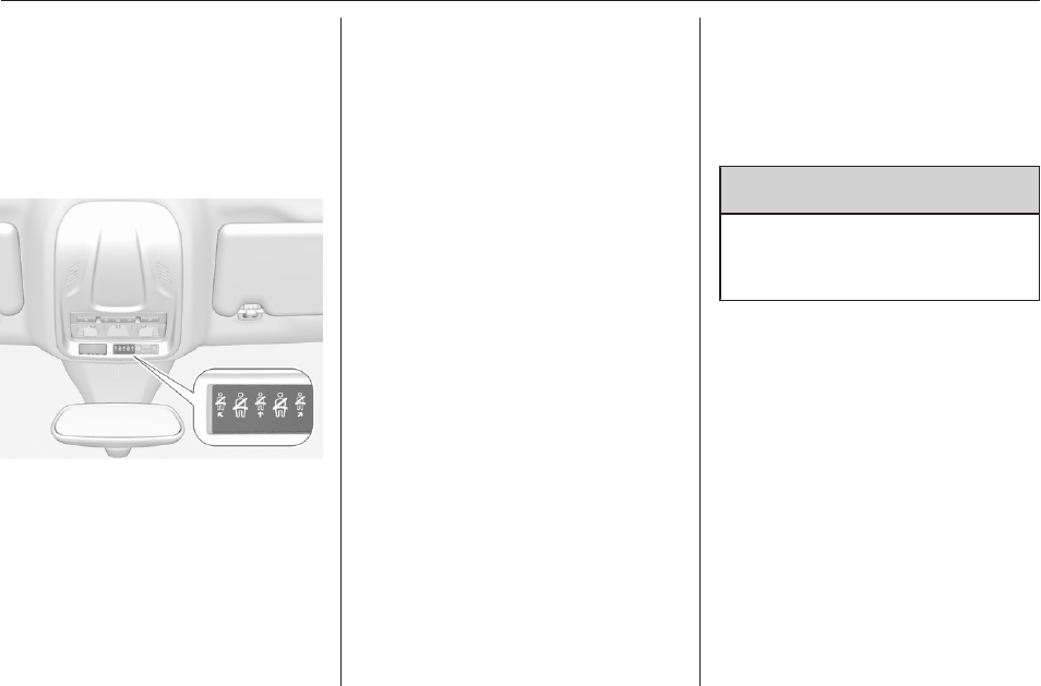
Instruments and controls 93
Seat belt reminder
Seat belt reminder on all seats
X illuminates or flashes red in the
instrument cluster together with the
indication in the roof console for each
seat belt.
● When the ignition is switched on,
X in the instrument cluster and
the symbol for the respective
seat in the roof console comes
on, if the seat belt of any
occupied seat has not been
fastened.
●After driving off, X in the
instrument cluster and the
symbol for the respective seat in
the roof console flashes for a
certain time together with a
chime. After a certain time of
driving X illuminates constantly
until the seat belt of the
respective seat has been
fastened or if any passenger has
unfastened the seat belt.
Seat belts 3 51.
Airbag and belt tensioners
v illuminates red.
When the ignition is switched on, the
control indicator illuminates for
approx. 4 seconds.
If it does not illuminate, does not
extinguish after 4 seconds or
illuminates whilst driving, there is a
fault in the airbag system. Seek the
assistance of a workshop. The
airbags and belt pretensioners may
fail to trigger in the event of an
accident.
Deployment of the belt pretensioners
or airbags is indicated by continuous
illumination of v.
9Warning
Have the cause of the fault
remedied immediately by a
workshop.
Belt pretensioners 3 51.
Airbag system 3 54.

94 Instruments and controls
Airbag deactivation
ÓON illuminates yellow.
The front passenger airbag is
activated.
*OFF illuminates yellow.
The front passenger airbag is
deactivated.
Airbag deactivation 3 59.
Charging system
p illuminates red.
Illuminates when the ignition is
switched on and extinguishes shortly
after the engine starts.
Illuminates when the engine is
running
Stop, switch off engine. Vehicle
battery is not charging. Engine
cooling may be interrupted. The
brake servo unit may cease to be
effective. Seek the assistance of a
workshop.
Malfunction indicator light
Z illuminates or flashes yellow.
Illuminates when the ignition is
switched on and extinguishes shortly
after the engine starts.
Illuminates when the engine is
running
Fault in the emission control system.
The permitted emission limits may be
exceeded. Seek the assistance of a
workshop immediately.
Flashes when the engine is
running
Fault that could lead to catalytic
converter damage. Ease up on the
accelerator until the flashing stops.
Seek the assistance of a workshop
immediately.
Service vehicle soon
C illuminates yellow.
Illuminates briefly when the ignition is
switched on.
May illuminate together with other
control indicators and a
corresponding message in the Driver
Information Centre.
Seek the assistance of a workshop
immediately.
Stop engine
Y illuminates red.
Illuminates briefly when the ignition is
switched on.

Instruments and controls 95
Illuminates together with other control
indicators, accompanied by a warning
chime and a corresponding message
in the Driver Information Centre.
Stop engine immediately and seek
the assistance of a workshop.
System check
J illuminates yellow or red.
Illuminates yellow
A minor engine fault has been
detected.
Illuminates red
A major engine fault has been
detected.
Stop engine as soon as possible and
seek the assistance of a workshop.
Hybrid system active
READY illuminates green. The hybrid
system ist active.
Hybrid system fault
i illuminates red.
The hybrid system has a fault.
Switch off ignition and seek the
assistance of a workshop.
Brake and clutch system
R illuminates red.
The brake and clutch fluid level is too
low.
9Warning
Stop. Do not continue your
journey. Consult a workshop.
Brake fluid 3 216.
Electric parking brake
m illuminates or flashes red.
Illuminates
Electric parking brake is applied
3 153.
Flashes
Electric parking brake is not applied
automatically. The application or the
release are faulty.
9Warning
Have the cause of the fault
remedied immediately by a
workshop.
o illuminates yellow.
Illuminates
Automatic operation is deactivated or
faulty. Activate automatic operation
again or have the cause remedied by
a workshop in the event of a fault.
Automatic operation 3 153.
Electric parking brake fault
E illuminates yellow.
Illuminates
Electric parking brake has a fault
3 153.
9Warning
Have the cause of the fault
remedied immediately by a
workshop.

96 Instruments and controls
Automatic operation of
electric parking brake off
o illuminates yellow.
Illuminates
Automatic operation is deactivated or
faulty. In the event of a fault, o
illuminates together with other control
indicators or it is accompanied by a
corresponding message in the Driver
Information Centre.
Activate automatic operation again or
have the cause remedied by a
workshop in the event of a fault.
Automatic operation 3 153.
Antilock brake system
(ABS)
u illuminates yellow.
Illuminates for a few seconds after the
ignition is switched on. The system is
ready for operation when the control
indicator extinguishes.
If the control indicator does not
extinguish after a few seconds, or if it
illuminates while driving, there is a
fault in the ABS. The brake system
remains operational but without ABS
regulation.
Antilock brake system 3 152.
Gear shifting
R with the number of a higher gear is
indicated, when upshifting is
recommended for fuel saving
reasons.
Lane departure warning
) illuminates green or flashes yellow.
Illuminates green
System is switched on and ready to
operate.
Flashes yellow
System recognises an unintended
lane change.
Lane departure warning 3 190.
Lane keep assist
a illuminates green or yellow, or
flashes yellow.
Illuminates green
The system is switched on and ready
to operate.
Illuminates yellow
The system approaches a detected
lane marking without using the turn
light in that direction.
Flashes yellow
The system recognizes that the lane
is departed significantly.
Lane keep assist 3 191.
Electronic Stability Control
and Traction Control system
b illuminates or flashes yellow.
Illuminates
A fault in the system is present.
Continued driving is possible. Driving
stability, however, may deteriorate
depending on road surface
conditions.
Have the cause of the fault remedied
by a workshop.

Instruments and controls 97
Flashes
The system is actively engaged.
Engine output may be reduced and
the vehicle may be braked
automatically to a small degree.
Electronic Stability Control and
Traction Control system 3 156.
Selective ride control 3 157.
Electronic Stability Control
and Traction Control system
off
9 illuminates yellow. The system has
been deactivated.
Electronic Stability Control and
Traction Control system 3 156.
Selective ride control 3 157.
Engine coolant temperature
o illuminates red.
Illuminates when the engine is
running
Stop, switch off engine.
Caution
Coolant temperature too high.
Check coolant level immediately
3 215.
If there is sufficient coolant, consult a
workshop.
Preheating
! illuminates yellow.
Preheating of diesel engine is
activated. Only activates when
outside temperature is low. Start the
engine when control indicator
extinguishes.
Starting the engine 3 136.
Exhaust filter
% or C illuminates yellow.
The exhaust filter requires cleaning.
Continue driving until the control
indicator extinguishes.
Illuminates temporarily
Start of saturation of the exhaust filter.
Start cleaning process as soon as
possible by driving at a vehicle speed
of at least 40 mph.
Illuminates constantly
Indication of a low additive level. Seek
the assistance of a workshop.
Exhaust filter 3 141.
AdBlue
Y flashes or illuminates yellow.
Illuminates yellow
The remaining driving range is
between 370 miles and 1500 miles.
Flashes yellow
The remaining driving range is
between 0 and 370 miles.
AdBlue level is low. Refill AdBlue
soon to avoid prevention of the
engine start. Up to 10 l of AdBlue can
be added.
AdBlue 3 142.

98 Instruments and controls
Deflation detection system
w illuminates or flashes yellow.
Illuminates
Tyre pressure loss in one or more
wheels. Stop immediately and check
tyre pressure.
Flashes
Fault in system. Consult a workshop.
Deflation detection system 3 232.
Engine oil pressure
I illuminates red.
Illuminates when the ignition is
switched on and extinguishes shortly
after the engine starts.
Illuminates when the engine is
running
Caution
Engine lubrication may be
interrupted. This may result in
damage to the engine and / or
locking of the drive wheels.
1. Select neutral gear.
2. Move out of the flow of traffic as
quickly as possible without
impeding other vehicles.
3. Switch off ignition.
9Warning
When the engine is off,
considerably more force is needed
to brake and steer. During an
Autostop the brake servo unit will
still be operational.
Do not remove key until vehicle is
stationary, otherwise the steering
wheel lock could engage
unexpectedly.
Keep engine turned off and let the
vehicle be towed to a workshop.
Low fuel
o illuminates yellow.
Level in fuel tank is too low.
Refuelling 3 203.
Bleeding the diesel fuel system
3 218.
Charge cord connected
j illuminates red.
The vehicle plug of the charge cord is
still connected to the charge port. The
vehicle cannot be started.
Disconnect the vehicle plug from the
charge port and close the charge port
door.
Autostop
D illuminates or flashes green.
Illuminates green
Engine is in an Autostop.
Flashes green
Autostop is temporarily unavailable,
or Autostop mode is invoked
automatically.
Stop-start system 3 138.
Exterior light
8 illuminates green.
The exterior lights are on 3 112.

Instruments and controls 99
Low beam
9 illuminates green.
Illuminated when low beam is on.
High beam
C illuminates blue.
Illuminates when high beam is on,
during headlight flash 3 113.
High beam assist
f illuminates green.
The high beam assist is activated
3 114.
LED headlights
C illuminates and a warning
message is displayed in the Driver
Information Centre.
Seek the assistance of a workshop.
Front fog lights
> illuminates green.
The front fog lights are on 3 118.
Rear fog light
r illuminates yellow.
The rear fog light is on 3 118.
Rain sensor
< illuminates green.
Illuminated when rain sensor position
on wiper lever is selected.
Windscreen wiper and washer 3 80.
Cruise control
m illuminates white or green.
Illuminates white
The system is on.
Illuminates green
Cruise control is active. Set speed is
indicated in the Driver Information
Centre.
Cruise control 3 159.
Adaptive cruise control
m illuminates white or green.
C illuminates in the Driver
Information Centre.
m illuminates white
The system is on.
m illuminates green
Adaptive cruise control is active.
When adaptive cruise control is on or
active, C with the set speed is
indicated in the Driver Information
Centre.
Adaptive cruise control 3 164.
Vehicle detected ahead
A illuminates green.
Illuminates green
A vehicle ahead is detected in the
same lane.
Adaptive cruise control 3 164.
Forward collision alert 3 170.
Side blind spot alert
B illuminates green.
The system is active 3 184.

100 Instruments and controls
Active emergency braking
m illuminates or flashes yellow.
Illuminates
The system has been deactivated or
a fault has been detected.
Additionally, a warning message is
displayed in the Driver Information
Centre.
Check the reason of the deactivation
3 172 and in case of a system fault,
seek the assistance of a workshop.
Notice
m also illuminates if the seat belts
of the front passengers are not
fastened. In this case, active
emergency braking is deactivated.
Flashes
The system is actively engaged.
Depending on the situation, the
vehicle may automatically brake
moderately or hard.
Forward collision alert 3 170.
Front pedestrian protection 3 175.
Speed limiter
ß illuminates in the Driver
Information Centre when speed
limiter is active. Set speed is indicated
alongside ß symbol.
Speed limiter 3 162.
Door open
h illuminates red.
A door or the tailgate is open.
Displays
Driver Information Centre
The Driver Information Centre is
located in the instrument cluster.
Driver Information Centre indicates:
● overall and trip odometer
● digital speed indication
● trip / fuel information menu
● gear shift indication
● service information
● vehicle and warning messages
● driver assistance messages
● pop-up messages
● AdBlue information
● powerflow
● range autonomy
Selecting menus and functions
The menus and functions can be
selected via the buttons on the
indicator lever.

Instruments and controls 101
Turn the adjuster wheel to select a
page in the trip / fuel information
menu.
Press SET / CLR to confirm or reset
a function.
Vehicle and service messages are
popped up in the Driver Information
Centre if required. Scroll messages
by turning the adjuster wheel.
Confirm messages by pressing
SET / CLR.
Additionally, some menus can be
selected via the CHECK button.
Press CHECK to switch between the
respective menus.
Vehicle messages 3 106.
Trip / fuel information menu
Differerent pages with combined
information can be selected.
Turn the adjuster wheel to select a
page.
Information page:
Fuel range
Range is calculated from current fuel
level and current consumption. The
display shows average values.
After refuelling, the range is updated
automatically after a brief delay.
When the fuel level is low, a message
appears on the display and the
control indicator o in the fuel gauge
illuminates 3 98.
Instantaneous Fuel Consumption
Display of the instantaneous
consumption.
Trip 1 page:
Average speed
Display of average speed. The
measurement can be reset at any
time.
Average fuel consumption

102 Instruments and controls
Display of average consumption. The
measurement can be reset at any
time and starts with a default value.
Distance travelled
Displays the current distance for trip
1 since the reset.
The values of trip 1 page can be reset
by pressing SET / CLR for a few
seconds.
Trip 2 page:
Average speed
Display of average speed. The
measurement can be reset at any
time.
Average fuel consumption
Display of average consumption. The
measurement can be reset at any
time and starts with a default value.
Distance travelled
Displays the current distance for trip
2 since a certain reset.
The values of trip 2 page can be reset
by pressing SET / CLR for a few
seconds.
Digital speed page
Digital display of the instantaneous
speed.
Autostop time counter
A time counter calculates the time
spent in Autostop during a journey. It
resets to zero every time the ignition
is switched on.
Compass page
Displays the geographic direction of
driving.
Blank page
No trip / fuel information is displayed.
AdBlue
Press CHECK repeatedly until the
AdBlue menu is shown.
AdBlue range
Indicates an estimate of the AdBlue
level. A message indicates whether
the level is sufficient or low.
3 142.
Powerflow
Displays the current powerflow in the
hybrid system, e.g., when the vehicle
is operating in electric mode or when
energy is regenerated.
Range autonomy
Displays the selected drive mode, the
range of the high voltage battery and
the combined range, i.e., the range of
the high voltage battery and the fuel
tank.
Info Display
The Info Display is located in the
instrument panel near the instrument
cluster.
Depending on the vehicle
configuration the vehicle has a
●Graphic Info Display
or
●7'' Colour Info Display with
touchscreen functionality
or
●8'' Colour Info Display with
touchscreen functionality

Instruments and controls 103
The Info Displays can indicate:
● time 3 83
● outside temperature 3 83
● date 3 83
● Infotainment system, see
description in the Infotainment
manual
● indication of rear view camera
3 188
● indication of panoramic view
system 3 185
● indication of parking assist
instructions 3 176
● navigation, see description in the
Infotainment manual
● vehicle and system messages
3 106
● settings for vehicle
personalisation 3 107
● indication of the current
powerflow within the hybrid
system
● indication of the average fuel and
power consumption
● settings for programmable
charging 3 197
● settings for eSave function
Graphic Info Display
Press X to switch on the display.
Press MENU to select main menu
page.
Press èäåé to select a menu page.
Press OK to confirm a selection.
Press BACK to exit a menu without
changing a setting.
7'' Colour Info Display
Selecting menus and settings
Menus and settings are accessed via
the display.
Press X to switch on the display.
Press ; to display the homepage.
Touch required menu display icon
with the finger.
Touch a respective icon to confirm a
selection.
Touch 9 to return to the next higher
menu level.
Press ; to return to the homepage.

104 Instruments and controls
For further information, see
Infotainment manual.
Vehicle personalisation 3 107.
8'' Colour Info Display
Selecting menus and settings
There are three options to operate the
display:
● via buttons below the display
● by touching the touchscreen with
the finger
● via speech recognition
Button and touch operation
Press X to switch on the display.
Press SET to select system settings
(units, language, time and date).
Press Í to select vehicle settings or
driving functions.
Touch required menu display icon or
a function with the finger.
Confirm a required function or
selection by touching.
Touch r on the display to exit a
menu without changing a setting.
For further information, see
Infotainment manual.
Speech recognition
Description see Infotainment manual.
Vehicle personalisation 3 107.
Powerflow
This menu displays the current
energy flow within the hybrid system.
The components will be highlighted
when they are active.
1. Press m.
2. Select Flow.
Different colours show which engine
is used and whether energy is
regenerated.
● green: electric engine operating
● orange: combustion engine
operating
● blue: regenerating energy
Average consumption
This menu displays the average
power and fuel consumption during
the current trip. The current trip is
subdivided into time steps. For each

Instruments and controls 105
time step, the average consumption
is displayed. The time steps can be
modified.
1. Press m.
2. Select Statistics.
3. Press + and - to modify the time
steps.
Power consumption
The consumption of electrial power is
displayed in kWh/100 miles.
● The green bars show the electric
energy comsumed from the
battery.
● The blue bars show the electric
energy generated from the
braking and deceleration phases
of the vehicle. This energy is
partially used to recharge the
battery.
Fuel consumption
The orange bars show the average
fuel consumption in litre per 100
miles.
eSave function
This function allows to provide
electrical energy of the high voltage
battery for a later use, e.g. for driving
in areas restricted to electrical
vehicles. It is possible to reserve the
complete electrical energy of the
battery or a part of it.
Notice
If the energy requested exceeds the
energy of the high voltage battery,
the combustion engine charges the
battery. This results in a loss of
performance and a higher fuel
consumption.
The function can be activated in the
Colour Info Display.
1. Press m.
2. Select eSave.
3. Select the distance for which
electrical is to be reserved or
reserve the whole capacity of the
high voltage battery.
4. Press ON.

106 Instruments and controls
5. To use the reserved electrical
energy change to electric mode.
The setting of this function is not
stored when the ignition is switched
off.
Smartphone app
With the myVauxhall smartphone
app, some vehicle functions can be
operated / displayed.
To operate these functions, download
the app from Apple App Store or
Google Play Store.
Vehicle messages
Messages are indicated in the Driver
Information Centre, in some cases
together with a warning chime.
Press SET / CLR to confirm a
message.
Vehicle and service messages
The vehicle messages are displayed
as text. Follow the instructions given
in the messages.
Messages in the
Colour Info Display
Some important messages may
appear additionally in the
Info Display. Some messages only
pop-up for a few seconds.
Warning chimes
The warning chime regarding not
fastened seat belts has priority over
any other warning chime.
When starting the engine or whilst
driving
A warning chime will sound when
● a seat belt is not fastened
● a door or the tailgate is not fully
closed
● a certain speed is exceeded with
parking brake applied
● cruise control deactivates
automatically
● a programmed speed or speed
limit is exceeded
● Ia warning message appears in
the Driver Information Centre

Instruments and controls 107
● the electronic key is not in the
passenger compartment
● the parking assist detects an
object
● an unintended lane change
occurs
● the exhaust filter has reached the
maximum filling level
If several warnings appear at the
same time, only one warning chime
will sound
When the vehicle is parked and /
or the driver's door is opened
● With exterior lights on.
During an Autostop
● If the driver's door is opened.
● If any condition for a restart of the
engine is not fulfilled.
Vehicle personalisation
The vehicle's behaviour can be
personalised by changing the settings
in the Info Display.
Depending on vehicle equipment and
country-specific regulations some of
the functions described below may
not be available.
Some functions are only displayed or
active when the engine is running.
Graphic Info Display
Press MENU to open the menu page.
Use four-way button to operate the
display:
Select ˆ Personalisation-
configuration I OK.
Unit settings
Select Display configuration I OK.
Select Choise of units I OK.
Select desired settings I OK.
Language settings
Select Display configuration I OK.
Select Choise of language I OK.
Select desired language I OK.
Vehicle settings
Select Define vehicle parameters I
OK.
In the corresponding submenus the
following settings can be changed:
●Lighting
Follow me home headlamps:
Activation and setting duration
time.
Welcome lighting: Activation and
setting duration time.
●Comfort
Ambient lighting: Activation /
deactivation.

108 Instruments and controls
Rear wiper in reverse gear:
Activation / deactivation.
●Vehicle
Unlocking boot only: Activation /
deactivation.
Plip action: Driver / all doors.
●Driving assistance
Fatigue Detection system:
Activation / deactivation.
Speed recommendation:
Activation / deactivation.
7" Colour Info Display
Unit settings
Select Units.
Change units for Consumption and
Distance and Temperature.
Language settings
Select Language.
Change language by touching the
respective entry.
Vehicle settings
Select Vehicle.
In the corresponding submenus the
following settings can be changed:
●Collision / Detection Systems
Side Blind Spot Alert: Activates
or deactivates side blind spot
alert.
Drowsy Driver Alert: Activates or
deactivates the driver
drowsiness system.
Speed Limit Information:
Activates or deactivates the
speed limit information by traffic
sign recognition.
Rear View Camera Guidelines:
Activates or deactivates the rear
view camera guidelines on the
Info Display.
Forward Collision Alert: Activates
or deactivates the forward
collision alert auto brake, adjusts
the sensitivity of the forward
collision alert.
●Comfort and Convenience
Auto Wipe in Reverse Gear:
Activates or deactivates
automatic switching on of the
rear window wiper when reverse
gear is engaged.
●Lighting
Ambient Lighting: Activates or
deactivates the ambient lighting
and adjusts its brightness.
Welcome Lighting: Activates or
deactivates and changes the
duration of welcome lighting.
Exit Lighting: Activates or
deactivates and changes the
duration of exit lighting.
●Remote Lock, Unlock, Start
Remote Door Unlock: Changes
the configuration to unlock the
driver's door only or all doors
when pressing O on the remote
control.

Instruments and controls 109
Unlock boot only: Activates or
deactivates unlocking the tailgate
only when pressing T on the
remote control.
8" Colour Info Display
Press SET to open settings menu.
Use touch buttons to operate the
display.
Unit settings
Select System settings.
Change units for Distance and fuel
consumption and Temperature.
Confirm with G.
Language settings
Select Languages.
Change language by touching the
respective entry.
Confirm with G.
Vehicle settings
Press Í.
Select Vehicle settings.
In the corresponding submenus the
following settings can be changed:
●Vehicle access
Door unlock: Driver only:
Changes the configuration to
unlock the driver's door only or all
doors when pressing O on the
remote control.
Door unlock: Boot only: Activates
or deactivates unlocking the
tailgate only when pressing T
on the remote control.
Motorised tailgate/door:
Activates or deactivates the
opening or closing of the power
tailgate.
Hands-Free opening: Activates
or deactivates the function.
●Safety
Recommended speed display:
Activates or deactivates the
speed limit information by traffic
sign recognition.
Active safety brake: Activates or
deactivates active emergency
braking and the forward collision
alert, the alert sensitivity can be
selected.
Mirror adaptation in reverse:
Adjusts the exterior mirrors if
reverse gear is engaged to
facilitate sidewalks visibility.

110 Instruments and controls
Driver's attention warning:
Activates or deactivates the
driver drowsiness system.
Rear wiper in reverse: Activates
or deactivates automatic
switching on of the rear window
wiper when reverse gear is
engaged.
●Driving lighting
Directional headlamps: Activates
or deactivates the function.
●Comfort lighting
Guide-me-home lighting:
Activates or deactivates the
function and adjusts its duration.
Welcome lighting: Activates or
deactivates the function and
adjusts its duration.
Mood lighting: Adjusts the
brightness of the ambient
lighting.
Driving functions
Press Í.
Select Driving functions.
In the corresponding submenus the
following settings can be changed:
●Park Assist: Activates advanced
park assist, a parking maneuver
can be selected.
●Blind spot sensors: Activates or
deactivates side blind spot alert.
●Panoramic view system:
Activation / deactivation of the
function.
Telematics services
Vauxhall Connect
Vauxhall Connect comprises multiple
connected services accessible via
app, online or within the vehicle.
Notice
Full functionality of
Vauxhall Connect is subject to
registration and proper activation.
Connected services may include live
navigation such as online traffic
information and vehicle status and
information such as maintenance
alerts.
Services accessible within the vehicle
also include emergency call and
breakdown call. These functions are
automatically activated. Terms and
conditions apply.
Emergency call function and
breakdown call function are operated
by the buttons in the overhead
console.

Instruments and controls 111
Status LED in the overhead
console
Illuminates green and red and
extinguishes after a short time, when
the ignition is switched on: the system
works properly.
Illuminates red: fault in the system.
Contact a workshop.
Flashes red: backup battery needs
replacement. Contact a workshop.
Emergency call
The emergency call function will
establish a connection to the nearest
public safety answering point (PSAP).
A minimum set of data including
vehicle and location information will
be sent to the PSAP.
Notice
Establishing an emergency call may
not be possible in areas without
sufficient network availability or due
to hardware damage during an
accident.
In case of an emergency, press the
red SOS button for more than
2 seconds. The LED flashes green to
confirm that a connection to the
nearest PSAP is being established.
The LED illuminates steadily as long
as the call is active.
Pressing the SOS button immediately
a second time will terminate the call.
The LED switches off.
Automatic crash notification
In case of an accident with airbag
deployment, an automatic
emergency call is established and an
automatic crash notification will be
transmitted to the next PSAP.
Breakdown call
Pressing the . button for more than
2 seconds connects you to a roadside
assistance service provider.
For information about coverage and
scope of services of the roadside
assistance, please refer to the
Service and warranty booklet.
Privacy settings
Privacy settings of Vauxhall Connect
can be configured in your vehicle.
This will impact the set of data being
sent, e.g., in case a breakdown call is
triggered.The emergency call
function will not be impacted.
Change the privacy settings in the
vehicle by simultaneously pressing
the . button and the SOS button.
Versions with navigation system:
privacy settings can also be changed
in the system settings menu.

112 Lighting
Lighting
Exterior lighting .......................... 112
Light switch .............................. 112
Automatic light control ............. 113
High beam ............................... 113
Headlight flash ......................... 113
Headlight range adjustment ....114
Headlights when driving
abroad .................................... 114
Daytime running lights ............. 114
LED headlights ........................ 114
Hazard warning flashers .......... 117
Turn lights ................................ 117
Front fog lights ......................... 118
Rear fog light ........................... 118
Parking lights ........................... 119
Reversing lights ....................... 119
Misted light covers ................... 119
Interior lighting ........................... 119
Instrument panel illumination
control ..................................... 119
Interior lights ............................ 120
Reading lights .......................... 120
Sunvisor lights ......................... 120
Lighting features ........................ 121
Centre console lighting ............ 121
Entry lighting ............................ 121
Exit lighting .............................. 121
Battery discharge protection .... 121
Exterior lighting
Light switch
Turn light switch:
AUTO : automatic light control
switches automatically
between daytime running
light and headlight
8: sidelights
9: headlights
When switching on the ignition,
automatic light control is active.
Control indicator 8 3 98.

Lighting 113
Tail lights
Tail lights are illuminated together
with low / high beam and sidelights.
Automatic light control
When the automatic light control
function is switched on and the
engine is running, the system
switches between daytime running
lights and headlights automatically
depending on the external lighting
conditions and information given by
the wiper system.
Make sure the sensor is not blocked
3 10, 3 38.
Daytime running light 3 114.
Automatic headlight activation
During poor lighting conditions the
headlights are switched on.
Additionally, headlights are switched
on if the windscreen wipers have
been activated for several wipes.
Tunnel detection
When a tunnel is entered, headlights
are switched on immediately.
High beam
Push to switch from low to high beam.
Pull to deactivate high beam.
High beam assist 3 114.
Headlight flash
Pull to activate the headlight flash.
Pull to deactivate high beam.

114 Lighting
Headlight range adjustment
Manual headlight range
adjustment
To adapt headlight range to the
vehicle load to prevent dazzling, turn
thumb wheel ? to required position.
0 : front seats occupied
1 : all seats occupied
2 : all seats occupied and load
compartment laden
3 : driver's seat occupied and load
compartment laden
Headlights when driving
abroad
When driving in countries where
traffic drives on the opposite side of
the road, the headlights have to be
adjusted.
1. With the engine switched off, pull
the indicator lever and hold.
2. Start the engine.
3. Hold the indicator lever for
another 5 seconds.
4. Release the indicator lever.
If the headlights are adjusted, a
message is displayed in the Driver
Information Centre each time the
engine is started.
To reverse the adjustment of the
headlights, repeat the steps
described above.
Daytime running lights
Daytime running lights increase
visibility of the vehicle during daylight.
They are switched on automatically
when the engine is running.
The system switches between
daytime running lights and low beam
automatically, depending on the
lighting conditions.
LED headlights
LED headlight system contains a
variety of particular LEDs in each
headlight which enables the control of
the adaptive forward lighting
functions.
Light distribution and intensity of light
are variably triggered depending on
the lighting conditions, road type and
driving situation. The vehicle adapts
the headlights automatically to the
situation to enable optimal light
performance for the driver.
Some adaptive forward lighting
functions of the LED headlights can
be deactivated or activated in the
vehicle personalisation menu. Select
the relevant setting in Settings I
Vehicle in the Info Display.
Vehicle personalisation 3 107.
The lighting functions are only
available with light switch in position
AUTO.

Lighting 115
Country light
Activated automatically at a speed
between 34 mph and 71 mph when
driving in rural areas. The illumination
of the current lane and the side of the
road is improved. Oncoming and
preceding vehicles are not dazzled.
Motorway light
Activated automatically at a speed
above 71 mph. Illumination is
adapted to the higher speed driven on
motorways. If there is no oncoming
traffic, the visibility on the side of the
vehicle is increased. The visibility
range raises from 70 m to 140 m
allowing distant objects to be
recognised across the entire width of
the road.
Town light
Activated automatically at a speed up
to approx. 34 mph and in situations
with exterior ambient light. The light is
wide and symmetrical. If the speed is
below 19 mph, the headlamps are
slightly swiveled to the outside to
allow an earlier recognition of
pedestrians and objects on each side
of the road. A special beam pattern is
designed to avoid glare for other road
users.
Corner light
Activated at a speed of up to 25 mph
when turning off. The light consists of
particular LEDs which illuminate the
direction of travel. These LEDs are
triggered depending on the steering
angle or the activation of the turn
lights.
Adverse weather light
Controlled by wiper or rain sensor.
The wide light distribution – slightly
swiveled to the outside – enables
improved orientation at the edge of
the road. The intensity of the light in
the far distance is increased in order

116 Lighting
to recognise objects and markings on
the right road side and obstacles on
the lane despite the weather
condition. By lowering the reflection
on wet roads the oncoming traffic is
less dazzled. Adverse weather light is
activated up to a speed to 43 mph.
Curve light
Particular LEDs, based on steering
angle and speed, are additionally
triggered to improve lighting in
curves. This function is activated at
speeds from 25 mph to 43 mph.
High beam assist
This feature activates the high beam
at night when the vehicle speed is
faster than 15 mph.
The camera in the windscreen
detects the lights of oncoming or
preceding vehicles. Each LED on
right or left side can be triggered or
faded out particularly according to the
traffic situation. This gives the best
light distribution without dazzling
other road users. Once activated,
high beam assist remains active and
switches high beam on and off
depending on surrounding
conditions. The latest setting of the
high beam assist will remain after the
ignition is switched on again.
High beam assist includes a special
motorway mode. When driving faster
than 71 mph on motorways, the light
beam becomes smaller to avoid
dazzling of oncoming traffic. When
following vehicles ahead or passing,
dazzling for these vehicles is
reduced.
Activation
Activate the high beam assist by
pressing f. The LED of the button
illuminates if the high beam assist is
activated. High beam is switched on
automatically at a speed above
15 mph. High beam is switched off at
a speed below 9 mph, but high beam
assist remains active.
The green control indicator f
illuminates continuously when the
high beam assist is activated, the blue
7 illuminates when high beam is on.
Control indicator f 3 99, 7 3 99.

Lighting 117
Pushing left indicator lever once
switches on manual high beam
without high beam assist.
High beam assist switches
automatically to low beam when:
● Driving in urban areas.
● Camera detects heavy fog.
● Front or rear fog lights are
switched on.
If there are no restrictions detected,
the system switches back to high
beam.
Deactivation
Deactivate the high beam assist by
pressing f.
If a headlight flash is activated when
the high beam assist is activated and
low beam is on, the high beam assist
will be deactivated. The system
changes to high beam.
If a headlight flash is activated when
the high beam assist is activated and
high beam is on, the high beam assist
will be deactivated. The system
changes to low beam.
To reactivate the high beam assist,
flash the headlights again.
Fault in LED headlight system
When the system detects a failure in
the LED headlight system, it selects a
preset position to avoid dazzling of
oncoming traffic. A warning is
displayed in the Driver Information
Centre.
Hazard warning flashers
Operated by pressing ¨.
When braking in an emergency, the
hazard warning flashers are switched
on automatically depending on the
force of deceleration. They are
switched off automatically the first
time you accelerate.
Turn lights
up : right turn lights
down : left turn lights
A resistance point can be felt when
moving the indicator lever.
Constant flashing is activated when
the indicator lever is being moved
beyond the resistance point. It is
deactivated when the steering wheel

118 Lighting
is moved in the opposite direction or
indicator lever is manually moved
back to its neutral position.
Activate temporary flashing by
holding the indicator lever just before
the resistance point. Turn lights will
flash until indicator lever is being
released.
To activate three flashes, tap the
indicator lever briefly without passing
the resistance point.
If you forget to cancel the turn lights
for more than 20 seconds, the volume
of the audible signal will increase if
the speed is above 40 mph.
Front fog lights
Operated by pressing >.
Light switch in position AUTO:
switching on front fog lights will switch
headlights on automatically.
Rear fog light
Operated by pressing r.
Light switch in position AUTO:
switching on rear fog light will switch
headlights on automatically.
Light switch in position 8: rear fog
light can only be switched on with
front fog lights.
The vehicle rear fog light is
deactivated when towing a trailer or a
plug is connected with the socket,
e.g. when a bicycle carrier is used.

Lighting 119
Parking lights
When the vehicle is parked, the
parking lights on one side can be
activated:
1. Switch off ignition.
2. Move the lever all the way up
(right parking lights) or down (left
parking lights).
Confirmed by a signal and the
corresponding turn lights control
indicator.
Reversing lights
The reversing light comes on when
the ignition is on and reverse gear is
selected.
Misted light covers
The inside of the light housing may
mist up briefly in poor, wet and cold
weather conditions, in heavy rain or
after washing. The mist disappears
quickly by itself. To help, switch on the
headlights.
Interior lighting
Instrument panel
illumination control
Brightness of the following lights can
be adjusted when the exterior lights
are on:
● instrument panel illumination
● Info Display
● illuminated switches and
operation elements
Turn thumb wheel A and hold until
the desired brightness is obtained.

120 Lighting
Interior lights
During entry and exit of the vehicle,
the front and rear courtesy lights
automatically switch on and then off
after a delay.
Notice
In the event of an accident with
airbag deployment the courtesy
lights are turned on automatically.
Front courtesy light
w: automatic switching on
and off
press u: on
press v: off
Rear courtesy lights
Illuminate in conjunction with the front
courtesy light.
Reading lights
Operated by pressing s and t in the
courtesy lights.
Illustration shows rear courtesy lights.
Sunvisor lights
Illuminates when the cover is opened.

Lighting 121
Lighting features
Centre console lighting
A spotlight integrated in the overhead
console illuminates the centre
console when headlights are
switched on.
Entry lighting
Welcome lighting
Some or all of the following lights are
switched on for a short time by
unlocking the vehicle with the radio
remote control:
● headlights
● puddle lights
● interior lights
The number of activated lights
depends on the surrounding light
conditions.
The lighting switches off immediately
when the ignition is switched on.
Starting off 3 17.
This function can be activated or
deactivated in the vehicle
personalisation.
Vehicle personalisation 3 107.
The following lights will additionally
switch on when the driver's door is
opened:
● illumination of some switches
● Driver Information Centre
● door pocket lights
Exit lighting
The following lights are switched on
when the ignition is switched off:
● headlights
● interior lights
● centre console lighting
They will switch off automatically after
a delay. This function works only in
the dark.
Battery discharge protection
To prevent discharge of the vehicle
battery when the ignition is switched
off, some interior lights are switched
off automatically after some time.

122 Climate control
Climate control
Climate control systems ............. 122
Heating and ventilation system 122
Air conditioning system ........... 123
Electronic climate control
system .................................... 126
Auxiliary heater ........................ 130
Parking heater ......................... 130
Air vents ..................................... 131
Adjustable air vents ................. 131
Fixed air vents ......................... 132
Glovebox cooler ...................... 132
Maintenance .............................. 132
Air intake ................................. 132
Air conditioning regular
operation ................................ 132
Service .................................... 132
Climate control systems
Heating and ventilation
system
Controls for:
● temperature £
●air distribution l, M and K
● fan speed Z
● demisting and defrosting à
● heated rear window and exterior
mirrors b
●heated seats ß
Heated rear window b 3 40.
Heated exterior mirrors b 3 37.
Heated seats ß 3 50.
Temperature
Adjust the temperature by turning
£ to the desired temperature.
red area : warmer
blue area : colder
Heating will not be fully effective until
the engine has reached normal
operating temperature.
Air distribution
l: to windscreen and front door
windows
M: to head area via adjustable air
vents
K: to foot well and windscreen
All combinations are possible.
Fan speed
Adjust the air flow by turning Z to the
desired speed.
clockwise : increase
anticlockwise : decrease

Climate control 123
Demisting and defrosting
● Press à: the air distribution is
directed towards the windscreen.
● Set temperature controller £ to
warmest level.
● Set fan speed Z to highest level.
● Switch on heated rear window b.
● Open side air vents as required
and direct them towards the door
windows.
Heated rear window, windscreen and
exterior mirrors b 3 40.
Heated seats ß 3 50.
Air conditioning system
Controls for:
● temperature £
●air distribution l, M and K
● fan speed Z
● demisting and defrosting à
● cooling A/C
●air recirculation 4
● heated rear window and exterior
mirrors b
● heated windscreen ,
●heated seats ß
Heated rear windowb3 40.
Heated exterior mirrors b3 37.
Heated windscreen , 3 41.
Heated seats ß 3 50.
Some setting changes are indicated
briefly in the Info Display. Activated
functions are indicated by the LED in
the respective button.
Temperature
Adjust the temperature by turning
£ to the desired temperature.
red area : warmer
blue area : colder

124 Climate control
Heating will not be fully effective until
the engine has reached normal
operating temperature.
Air distribution
l: to windscreen and front door
windows
M: to head area via adjustable air
vents
K: to foot well and windscreen
All combinations are possible.
Fan speed
Adjust the air flow by turning Z to the
desired speed.
clockwise : increase
anticlockwise : decrease
Cooling A/C
Press A/C to switch on cooling. The
LED in the button illuminates to
indicate activation. Cooling is only
functional when the engine is running
and fan is switched on.
Press A/C again to switch off cooling.
The air conditioning system cools and
dehumidifies (dries) as soon as the
outside temperature is slightly above
the freezing point. Therefore,
condensation may form and drip from
under the vehicle.
If no cooling or drying is required,
switch off the cooling system for fuel
saving reasons.
Activated cooling may inhibit
Autostops.
Stop-start system 3 138.
Air recirculation system
Press 4 to activate air recirculation
mode. The LED in the button
illuminates to indicate activation.
Press 4 again to deactivate air
recirculation mode.
9Warning
The exchange of fresh air is
reduced in air recirculation mode.
In operation without cooling the air

Climate control 125
humidity increases, so the
windows may mist up from inside.
The quality of the passenger
compartment air deteriorates,
which may cause the vehicle
occupants to feel drowsy.
In warm and very humid ambient air
conditions, the windscreen may mist
up from outside when cold air is
directed towards it. If windscreen
mists up from outside, activate
windscreen wiper and deactivate l.
Maximum cooling
Briefly open the windows so that hot
air can disperse quickly.
● Switch on cooling A/C.
●Press 4 for air recirculation
system on.
●Press M for air distribution.
● Set temperature control £ to
coldest level.
● Set fan speed Z to highest level.
● Open all vents.
Heated rear window, windscreen and
exterior mirrors b 3 40.
Heated seats ß 3 50.
Demisting and defrosting the
windows
● Press à: the air distribution is
directed towards the windscreen.
● Set temperature controller £ to
warmest level.
● Switch on cooling A/C, if
required.
● Set fan speed Z to highest level.
● Switch on heated rear window b.
● Switch on heated
windscreen ,.
● Open side air vents as required
and direct them towards the door
windows.
Notice
If à is pressed while the engine is
running, an Autostop will be inhibited
until à is pressed again.
If à is pressed while the engine is in
an Autostop, the engine will restart
automatically.
Stop-start system 3 138.

126 Climate control
Electronic climate control
system
The dual zone climate control allows
different temperatures for driver side
and front passenger side.
In automatic mode, temperature, fan
speed and air distribution are
regulated automatically.
Controls for:
● temperature on driver side £
●MENU enters the Climate setting
menu in the Info Display
● fan speed Z
● automatic mode AUTO
● temperature on front passenger
side £
● cooling A/C
●manual air recirculation 4
● demisting and defrosting à
● heated rear window and exterior
mirrors b
● heated windscreen ,
●heated seats ß
●ventilated seats A
Heated rear window Ü 3 40.
Heated exterior mirrors Ü 3 37.
Heated seats ß 3 50.
Ventilated seats A 3 50.
Activated functions are indicated by
the LED in the respective control.
The electronic climate control system
is only fully operational when the
engine is running.
Make sure the sun sensor used by the
electronic climate control system is
not covered 3 10.
Climate control settings menu
Press MENU to manually set the
following climate control functions:
●air distribution l, M, K
● fan speed Z
● temperature for driver and
passenger side
● dual zone temperature
synchronisation MONO
● cooling A/C
● automatic mode AUTO

Climate control 127
Climate setting menu can also be
displayed:
● by selecting Climate on the
7'' Colour Info Display or
● by pressing Í and then selecting
Climate from the menu on the
8'' Colour Info Display.
Automatic mode AUTO
Basic setting for maximum comfort:
● Press AUTO, the air distribution
and fan speed are regulated
automatically.
● Open all air vents to allow
optimised air distribution in
automatic mode.
● Air conditioning must be
activated for optimal cooling and
demisting. Press A/C to switch on
air conditioning. The LED in the
button indicates activation.
● Set the preselected
temperatures for driver and front
passenger using the left and right
rotary ring. Recommended
temperature is 22 °C.
Manual settings
Climate control system settings can
be changed by activating the
following functions:
Fan speed Z
Adjust the air flow by turning rotary
ring to the desired speed. Turn
anticlockwise to decrease or turn
clockwise to increase. Fan speed can
also be changed in the climate
settings menu. Press MENU to enter
the menu.
Turn rotary ring anticlockwise as far
as it will go: fan and cooling are
switched off.
To return to automatic mode, press
AUTO.
Air distribution l, M, K
Press MENU to enter the menu.

128 Climate control
Touch in the Colour Info Display:
l: to windscreen and front door
windows
M: to head area and rear seats via
adjustable air vents
K: to front and rear foot well and
windscreen
To return to automatic air distribution,
press AUTO.
Temperature preselection £
Set the preselected temperatures
separately for the driver and the front
passenger to the desired value using
the left and right rotary ring. The
rotary ring on the passenger side
changes the temperature of the
passenger side. The rotary ring on the
driver's side changes the temperature
of the driver's side or of both sides,
depending on activation of
synchronisation MONO in the climate
settings menu. Press MENU to enter
the menu.
Recommended temperature is 22 °C.
Temperature is indicated in displays
beside the rotary rings and in the
climate settings menu.
If the minimum temperature Lo is set,
the climate control system runs at
maximum cooling, if cooling A/C is
switched on.
If the maximum temperature Hi is set,
the climate control system runs at
maximum heating.
Notice
If A/C is switched on, reducing the
set cabin temperature can cause the
engine to restart from an Autostop or
inhibit an Autostop.
Stop-start system 3 138.
Dual zone temperature
synchronisation MONO or SYNC
Press MENU to enter the menu.
Touch MONO or SYNC to link
passenger side temperature setting
to the driver side.
When passenger side control dial will
be adjusted, synchronisation is
deactivated.
Air conditioning A/C
Press A/C to switch on cooling. The
LED in the button illuminates to
indicate activation. Cooling is only
functional when the engine is running
and climate control fan is switched on.

Climate control 129
Press A/C again to switch off cooling.
The air conditioning system cools and
dehumidifies (dries) when outside
temperature is above a specific level.
Therefore condensation may form
and drip from under the vehicle.
If no cooling or drying is required,
switch off the cooling system for fuel
saving reasons.
Manual air recirculation 4
Press 4 to activate the air
recirculation mode. The LED in the
button illuminates to indicate
activation.
Press 4 again to deactivate
recirculation mode.
9Warning
The exchange of fresh air is
reduced in air recirculation mode.
In operation without cooling, the
air humidity increases, so the
windows may mist up from inside.
The quality of the passenger
compartment air deteriorates,
which may cause the occupants to
feel drowsy.
In warm and very humid ambient air
conditions, the windscreen may mist
up from outside, when cold air is
directed towards it. If windscreen
mists up from outside, activate
windscreen wiper and deactivate l.
Demisting and defrosting the
windows à
● Press à. The LED in the button
illuminates to indicate activation.
● Temperature and air distribution
are set automatically and the fan
runs at high speed.
● Switch on air conditioning by
pressing A/C, if required.
● Switch on heated rear window b.
● Switch on heated
windscreen ,.
● To return to previous mode,
press à again. To return to
automatic mode, press AUTO.

130 Climate control
Notice
If à is pressed while the engine is
running, an Autostop will be inhibited
until à is pressed again.
If à is pressed while the engine is in
an Autostop, the engine will restart
automatically.
Stop-start system 3 138.
Deactivation of electronic climate
control system
Cooling, fan and automatic mode can
be switched off by turning the rotary
ring around the AUTO button
anticlockwise.
Activation by switching on the fan or
pressing AUTO.
Heated rear window, windscreen and
exterior mirrors b 3 40.
Heated seats ß 3 50.
Auxiliary heater
Air heater
Quickheat is an electric auxiliary air
heater which automatically warms up
the passenger compartment more
quickly.
Parking heater
The parking heater allows to heat the
vehicle's interior and to ventilate the
vehicle's interior with ambient air.
The operating status of the parking
heater is shown by an indicator with a
LED.
● LED illuminates: A timer has
been set.
● LED flashes: The system is
operating.
The LED is extinguished at the end of
the heating operation or when the
parking heater is stopped using the
remote control.
The parking heater can be
programmed using the Graphic Info
Display / Colour Info Display.
Additionally, the parking heater can
be switched on and off using a remote
control.
Notice
The programmed heating /
ventilation is only activated if the
ignition is off and the vehicle is
locked.
If the charging level of the high
voltage battery is below 50%, the
programmed heating / ventilation is
not activated.
If a recurrent heating / ventilation is
programmed and two heating /
ventilation procedures are carried
out without operating the vehicle, the
programmation is deactivated.

Climate control 131
Colour Info Display
Press MENU to enter the menu.
Select Temperature conditioning.
Select heating or ventilation.
Define a timer.
Save the timer settings.
Activate the timer.
Air vents
Adjustable air vents
Air vents in the instrument panel
Direct the flow of air by tilting and
swivelling the slats.
To close the vent, swivel the slats
inwards.
Outer air vents in the instrument
panel
Direct the flow of air by tilting and
swivelling the slats.
To close the vent, swivel the slats
outwards.
At least two air vents must be open
while cooling is on.
9Warning
Do not attach any objects to the
slats of the air vents. Risk of
damage and injury in case of an
accident.

132 Climate control
Fixed air vents
Additional air vents are located
beneath the windscreen and door
windows and in the foot wells.
Glovebox cooler
The air conditioning system draws
cooled air into the glovebox through a
noozle.
Move the slider back or forth in order
to enable or disable glovebox cooling.
Maintenance
Air intake
The air intake in front of the
windscreen in the engine
compartment must be kept clear to
allow air intake. Remove any leaves,
dirt or snow.
Air conditioning regular
operation
In order to ensure continuously
efficient performance, cooling must
be operated for a few minutes once a
month, irrespective of the weather
and time of year. Operation with
cooling is not possible when the
outside temperature is too low.
Service
For optimal cooling performance, it is
recommended to annually check the
climate control system, starting
three years after initial vehicle
registration, including:
● functionality and pressure test
● heating functionality
● leakage check
● check of drive belts
● cleaning of condenser and
evaporator drainage
● performance check

Driving and operating 133
Driving and
operating
Driving hints ............................... 134
Control of the vehicle ............... 134
Steering ................................... 134
Starting and operating ............... 134
New vehicle running-in ............ 134
Ignition switch positions ........... 134
Power button ........................... 135
Starting the engine .................. 136
Overrun cut-off ........................ 138
Stop-start system .................... 138
Parking .................................... 140
Engine exhaust .......................... 141
Exhaust filter ............................ 141
Catalytic converter ................... 142
AdBlue ..................................... 142
Automatic transmission electri‐
fied ............................................. 146
Automatic transmission .............. 147
Transmission display ............... 147
Gear selection ......................... 147
Manual mode ........................... 148
Electronic driving programmes 149
Fault ........................................ 149
Interruption of power supply .... 149
Manual transmission .................. 150
Drive systems ............................ 151
Drive modes ............................ 151
All-wheel drive ......................... 151
Brakes ........................................ 152
Antilock brake system ............. 152
Parking brake .......................... 153
Brake assist ............................. 155
Hill start assist ......................... 155
Regenerative braking .............. 155
Ride control systems ................. 156
Electronic Stability Control and
Traction Control system ......... 156
Selective ride control ............... 157
Sport mode .............................. 158
Driver assistance systems ......... 159
Cruise control .......................... 159
Speed limiter ........................... 162
Adaptive cruise control ............ 164
Forward collision alert ............. 170
Active emergency braking ....... 172
Front pedestrian protection ..... 175
Parking assist .......................... 176
Advanced parking assist ......... 179
Side blind spot alert ................. 184
Panoramic view system ........... 185
Rear view camera ................... 188
Lane departure warning .......... 190
Lane keep assist ..................... 191
Driver alert ............................... 193
Charging .................................... 194
Programmable charging .......... 197
Charging status ....................... 198
Charge cord ............................. 198
Fuel ............................................ 201
Fuel for petrol engines ............. 201
Fuel for diesel engines ............ 202
Refuelling ................................ 203
Trailer hitch ................................ 205
General information ................. 205
Driving characteristics and
towing tips .............................. 205
Trailer towing ........................... 205
Towing equipment ................... 206
Trailer stability assist ............... 208

134 Driving and operating
Driving hints
Control of the vehicle
Never coast with engine not
running
Many systems will not function in this
situation (e.g. brake servo unit, power
steering). Driving in this manner is a
danger to yourself and others.
All systems function during an
Autostop.
Stop-start system 3 138.
Pedals
To ensure the pedal travel is
uninhibited, there must be no mats in
the area of the pedals.
Use only floor mats, which fit properly
and are fixed by the retainers on the
driver side.
Steering
If power steering assist is lost
because the engine stops or due to a
system malfunction, the vehicle can
be steered but may require increased
effort.
Starting and operating
New vehicle running-in
Do not brake unnecessarily hard for
the first few journeys.
During the first drive, smoke may
occur because of wax and enginge oil
evaporating off the exhaust system.
Park the vehicle in the open for a
while after the first drive and avoid
inhaling the fumes.
During the running-in period, fuel and
engine oil consumption may be
higher.
Additionally, the cleaning process of
the exhaust filter may take place more
often.
Exhaust filter 3 141.
Ignition switch positions
Turn key:

Driving and operating 135
0: ignition off: some functions
remain active until key is
removed or driver's door is
opened, provided the ignition was
on previously
1: ignition on power mode: ignition
is on, diesel engine is preheating,
control indicators illuminate and
most electrical functions are
operable
2: engine start: release key after
engine has been started
Steering wheel lock
Remove key from ignition switch and
turn steering wheel until it engages.
9Danger
Never remove the key from
ignition switch during driving as
this will cause steering wheel lock.
Power button
The electronic key must be inside the
vehicle.
Engine start
Operate the clutch pedal (manual
transmission), the brake pedal and
press Start/Stop.
Ignition on power mode without
starting the engine
Press Start/Stop without operating
clutch or brake pedal. Control
indicators illuminate and most
electrical functions are operable.
Engine and ignition off
Press Start/Stop briefly in each mode
or when engine is running and vehicle
is stationary. Some functions remain
active until driver's door is opened,
provided the ignition was on
previously.
Emergency shut off during driving
Press Start/Stop for 5 seconds
3 136. Steering wheel locks as soon
as vehicle is stationary.
Steering wheel lock
The steering wheel lock activates
automatically when:
● The vehicle is stationary.
● The ignition has been switched
off.
To release steering wheel lock, open
and close driver's door and switch the
ignition on power mode or start the
engine directly.

136 Driving and operating
9Warning
If the vehicle battery is discharged,
the vehicle must not be towed,
tow-started or jump-started as the
steering wheel lock cannot be
disengaged.
Operation on vehicles with
electronic key system in case of
failure
If either the electronic key fails or the
battery of the electronic key is weak,
a message may be displayed in the
Driver Information Centre.
Hold the electronic key with buttons
outside at the marking on the steering
column cover as shown in the
illustration.
Operate the clutch pedal (manual
transmission), the brake pedal and
press Start/Stop.
This option is intended for
emergencies only. Replace the
electronic key battery as soon as
possible 3 22.
For unlocking or locking the doors,
see fault in radio remote control unit
or electronic key system 3 23.
Starting the engine
Vehicles with ignition switch
Turn key to position 1 to release the
steering wheel lock.
Manual transmission: operate clutch
and brake pedal.
Automatic transmission: operate
brake pedal and move selector lever
to P or N.
Do not operate accelerator pedal.
Diesel engines: wait until control
indicator ! extinguishes.

Driving and operating 137
Turn key briefly to position 2 and
release after engine has been
started.
Manual transmission: during an
Autostop, the engine can be started
by depressing the clutch pedal
3 138.
Automatic transmission: during an
Autostop, the engine can be started
by releasing the brake pedal 3 138.
Vehicles with power button
● Manual transmission: operate
clutch and brake pedal.
● Automatic transmission: operate
brake pedal and move selector
lever to P or N.
● Do not operate accelerator pedal.
● Press Start/Stop button.
● Release button after starting
procedure begins. Diesel engine
starts after control indicator ! for
preheating extinguishes.
● Before restarting or to switch off
the engine when vehicle is
stationary, press Start/Stop once
more briefly.
To start the engine during an
Autostop:
● Manual transmission: during an
Autostop, the engine can be
started by depressing the clutch
pedal 3 138.
● Automatic transmission: during
an Autostop, the engine can be
started by releasing the brake
pedal 3 138.
Hybrid vehicles
● Press Start/Stop button.
● Depress brake pedal.
● Press Start/Stop button.
● Keep the brake pedal depressed
until the activation of the hybrid
system is confirmed by the
illumination of READY in the
instrument cluster and an
accoustic signal.
Emergency shut off during driving
If the engine needs to be switched off
during driving in case of emergency,
press Start/Stop for 5 seconds.
9Danger
Switching off the engine during
driving may cause loss of power
support for brake and steering
systems. Assistance systems and
airbag systems are disabled.
Lighting and brake lights will
extinguish. Therefore power down
the engine and ignition while
driving only when required in case
of emergency.

138 Driving and operating
Starting the vehicle at low
temperatures
Starting the engine without additional
heaters is possible down to -25 °С for
diesel engines and -30 °C for petrol
engines. Required is an engine oil
with the correct viscosity, the correct
fuel, performed services and a
sufficiently charged vehicle battery.
With temperatures below -30 °C the
automatic transmission requires a
warming phase of approx. 5 minutes.
The selector lever must be in position
P.
Turbo engine warm-up
Upon start-up, engine available
torque may be limited for a short time,
especially when the engine
temperature is cold. The limitation is
to allow the lubrication system to fully
protect the engine.
Overrun cut-off
The fuel supply is automatically cut off
during overrun, i.e. when the vehicle
is driven with a gear engaged but
accelerator pedal is released.
Depending on driving conditions, the
overrun cut-off may be deactivated.
Stop-start system
The stop-start system helps to save
fuel and to reduce the exhaust
emissions. When conditions allow, it
switches off the engine as soon as the
vehicle is at a low speed or at a
standstill, e.g. at a traffic light or in a
traffic jam.
Activation
The stop-start system is available as
soon as the engine is started, the
vehicle starts-off and the conditions
as stated below in this section are
fulfilled.
The system is ready to operate when
the LED in the button Ò is not
illuminated. To activate the system
when the system is deactivated,
press Ó.
If the stop-start system is temporarily
not available and the button Ò is
pressed, the LED in the button
flashes.
Deactivation
Deactivate the stop-start system
manually by pressing Ò. The
deactivation is indicated when the
LED in the button illuminates.
Autostop
Vehicles with manual transmission
An Autostop can be activated at a
standstill.
Activate an Autostop as follows:
● Depress the clutch pedal.
● Set the selector lever to neutral.
● Release the clutch pedal.

Driving and operating 139
The engine will be switched off while
the ignition stays on.
Vehicles with automatic transmission
If the vehicle is at a standstill with
depressed brake pedal, Autostop is
activated automatically.
The engine will be switched off while
the ignition stays on.
The stop-start system will be disabled
on inclines of 12% or more.
Indication
An Autostop is indicated by control
indicator D.
During an Autostop, the heating and
brake performance will be
maintained.
Conditions for an Autostop
The stop-start system checks if each
of the following conditions is fulfilled.
● The stop-start system is not
manually deactivated.
● The driver's door is closed or the
driver's seat belt is fastened.
● The vehicle battery is sufficiently
charged and in good condition.
● The engine is warmed up.
● The engine coolant temperature
is not too high.
● The engine exhaust temperature
is not too high, e.g. after driving
with high engine load.
● The ambient temperature is not
too low or too high.
● The climate control system
allows an Autostop.
● The brake vacuum is sufficient.
● The self-cleaning function of the
exhaust filter is not active.
● The vehicle was driven at least at
walking speed since the last
Autostop.
Otherwise an Autostop will be
inhibited.
Notice
The Autostop may be inhibited for
several hours after a battery
replacement or reconnection.
Certain settings of the climate control
system may inhibit an Autostop.
Climate control 3 123.
Immediately after higher speed
driving an Autostop may be inhibited.
New vehicle running-in 3 134.
Vehicle battery discharge protection
To ensure reliable engine restarts,
several vehicle battery discharge
protection features are implemented
as part of the stop-start system.
Power saving measures
During an Autostop, several electrical
features such as auxiliary electric
heater or rear window heating are
disabled or switched to a power
saving mode. The fan speed of the
climate control system is reduced to
save power.

140 Driving and operating
Restart of the engine by the driver
Vehicles with manual transmission
Depress the clutch pedal without
depressing the brake pedal to restart
the engine.
Vehicles with automatic transmission
The engine is restarted in the
following cases:
● brake pedal released while the
selector lever in position D or M
● brake pedal released or selector
lever in position N when selector
lever is moved to position D or
M
● selector lever moved to position
R
Restart of the engine by the stop-
start system
The selector lever must be in neutral
to enable an automatic restart.
If one of the following conditions
occurs during an Autostop, the
engine will be restarted automatically
by the stop-start system:
● stop-start system manually
deactivated
● driver's seat belt unfastened and
driver's door opened
● engine temperature too low
● charging level of vehicle battery
below a defined level
● brake vacuum not sufficient
● vehicle driven at least at walking
speed
● climate control system requests
engine start
● air conditioning manually
switched on
If an electrical accessory, e.g. a
portable CD player, is connected to
the power outlet, a brief power drop
during the restart might be noticeable.
Parking
9Warning
● Do not park the vehicle on an
easily ignitable surface. The
high temperature of the
exhaust system could ignite the
surface.
● Apply the parking brake.
● If the vehicle is on a level
surface or uphill slope, engage
first gear or set the selector
lever to position P. On an uphill
slope, turn the front wheels
away from the kerb.
If the vehicle is on a downhill
slope, engage reverse gear or
set the selector lever to position
P. Turn the front wheels
towards the kerb.
● Close the windows.
● Switch off the engine.
● Remove the ignition key from
the ignition switch or switch off
ignition on vehicles with power

Driving and operating 141
button. Turn the steering wheel
until the steering wheel lock is
felt to engage.
● For hybrid vehicles, make sure
READY is not illuminated in the
instrument cluster.
● Lock the vehicle.
● Activate the anti-theft alarm
system.
● The engine cooling fans may run
after the engine has been
switched off 3 213.
Caution
After running at high engine
speeds or with high engine loads,
operate the engine briefly at a low
load or run in neutral for
approx. 30 seconds before
switching off, in order to protect
the turbocharger.
Notice
In the event of an accident with
airbag deployment, the engine is
switched off automatically if the
vehicle comes to a standstill within a
certain time.
In countries with extreme low
temperatures it may be necessary to
park the vehicle without applied
parking brake. Make sure to park the
vehicle on a level surface.
Engine exhaust
9Danger
Engine exhaust gases contain
poisonous carbon monoxide,
which is colourless and odourless
and could be fatal if inhaled.
If exhaust gases enter the interior
of the vehicle, open the windows.
Have the cause of the fault
rectified by a workshop.
Avoid driving with an open load
compartment, otherwise exhaust
gases could enter the vehicle.
Exhaust filter
Automatic cleaning process
The exhaust filter system filters soot
particles out of the exhaust gases.
The start of saturation of the exhaust
filter is indicated by the temporary
illumination of % or C,
accompanied by a message in the
Driver Information Centre.

142 Driving and operating
As soon as the traffic conditions
permit, regenerate the filter by driving
at a vehicle speed of at least 40 mph
until the control indicator
extinguishes.
Notice
On a new vehicle, the first exhaust
filter regeneration operations may
be accompanied by a burning smell,
which is normal. Following
prolonged operation of the vehicle at
very low speed or at idle, water
vapour can be emitted at the
exhaust on acceleration. This does
not affect the behaviour of the
vehicle or the environment.
Cleaning process not possible
If % or C stays on, accompanied
by an audible signal and a message,
this indicates that the exhaust filter
additive level is too low.
The reservoir must be topped-up
without delay. Seek the assistance of
a workshop.
Catalytic converter
The catalytic converter reduces the
amount of harmful substances in the
exhaust gases.
Caution
Fuel grades other than those listed
on pages 3 201, 3 260 could
damage the catalytic converter or
electronic components.
Unburnt petrol will overheat and
damage the catalytic converter.
Therefore avoid excessive use of
the starter, running the fuel tank
dry and starting the engine by
pushing or towing.
In the event of misfiring, uneven
engine running, a reduction in engine
performance or other unusual
problems, have the cause of the fault
rectified by a workshop as soon as
possible. In an emergency, driving
can be continued for a short period,
keeping vehicle speed and engine
speed low.
AdBlue
General information
The selective catalytic reduction
(BlueInjection) is a method to
substantially reduce the nitrogen
oxides in the exhaust emission. This
is achieved by injecting a Diesel
Exhaust Fluid (DEF) into the exhaust
system. The ammonia released by
the fluid reacts with nitrous gases
(NOx) from the exhaust and turns it
into nitrogen and water.
The designation of this fluid is
AdBlue®. It is a non-toxic, non-
flammable, colourless and odourless
fluid which consists of 32% urea and
68% water.
9Warning
Avoid contact of your eyes or skin
with AdBlue.
In case of eye or skin contact,
rinse off with water.

144 Driving and operating
chime will sound. Driving is
possible without any restrictions.
If it is a temporary fault, the alert
disappears during the next
journey, after self-diagnosis of the
emissions control system.
2. If the fault is confirmed by the
emission control system, the
following message will be
displayed:
Emissions fault: Starting
prevented in 650 miles.
Additionally, control indicators u,
C and Z will illuminate and a
chime will sound.
When driving, the message is
displayed every 30 seconds while
the fault persists.
3. If the last warning level is entered,
the following warning message
will be displayed:
Emissions fault: Starting
prevented
Additionally, control indicators u,
C and Z will illuminate and a
chime will sound.
Consult a workshop for
assistance.
Refilling AdBlue
Caution
Only use AdBlue that complies
with European standards
DIN 70 070 and ISO 22241-1.
Do not use additives.
Do not dilute AdBlue.
Otherwise the selective catalytic
reduction system could be
damaged.
Notice
Whenever a filling pump with a
nozzle for passenger cars is not
available at a filling station, use only
AdBlue bottles or canisters with a
sealed refill adapter for refilling, to
prevent splashback and overspill,
and in order to ensure that the fumes
from the tank are captured and do
not emerge. AdBlue in bottles or
canisters is available in many filling
stations and can be purchased e.g.
at Vauxhall dealers and other retail
outlets.
Since AdBlue has a limited
durability, check the date of expiry
before refilling.
Notice
Refill the tank to a level of at least
5 l to ensure that the new AdBlue
level is being detected.
In case AdBlue refill is not
successfully detected:
1. Continuously drive the vehicle
for 10 min making sure that
vehicle speed is always higher
than 12 mph.
2. If AdBlue refill is detected
successfully, AdBlue supply-
driven warnings or limitations will
disappear.
If AdBlue refill is still not detected,
seek the assistance of a workshop.
If AdBlue must be refilled at
temperatures below -11 °C, the
refilling of AdBlue may not be
detected by the system. In this

Driving and operating 145
event, park the vehicle in a space
with a higher ambient temperature
until AdBlue is liquified.
Notice
When unscrewing the protective cap
from the filler neck, ammonia fumes
may emerge. Do not inhale as the
fumes have a pungent smell. The
fumes are not harmful by inhalation.
The AdBlue tank should be filled
completely. This must be done if the
warning message regarding
prevention of an engine restart is
already displayed.
The vehicle must be parked on a level
surface.
The filler neck for AdBlue is located
behind the fuel filler flap, which is
located at right rear side of the
vehicle.
The fuel filler flap can only be opened
if the vehicle is unlocked.
1. Remove key from ignition switch.
2. Close all doors to avoid ammonia
fumes entering the interior of the
vehicle.
3. Release the fuel filler flap by
pushing the flap 3 203.
4. Unscrew protective cap from the
filler neck.
5. Open AdBlue canister.
6. Mount one end of the hose on the
canister and screw the other end
on the filler neck.
7. Lift the canister until it is empty, or
until the flow from the canister has
stopped. This can take up to
5 minutes.
8. Place the canister on the ground
to empty the hose, wait
15 seconds.
9. Unscrew the hose from the filler
neck.
10. Mount the protective cap and turn
clockwise until it engages.
Notice
Dispose of AdBlue canister
according to environmental
requirements. Hose can be reused
after flushing with clear water before
AdBlue dries out.

146 Driving and operating
Automatic transmission
electrified
This vehicle is a plug-in hybrid
vehicle. It has a combustion engine
and an automatic transmission with
integrated electrical engine which
enables electrical driving and
charging of the battery during the
deceleration and the braking of the
vehicle. Additionally, the battery can
be charged using a cable, e.g., at
domestic electric outlets or public
charging stations. The all-wheel drive
version has a second electrical
engine for the rear axle.
Gear selection
P: park position, front wheels are
locked, engage only when the
vehicle is stationary and the
parking brake is applied
R: reverse gear, engage only
when the vehicle is stationary
N/P : neutral
D/B : automatic mode / automatic
mode with one-pedal driving
Do not accelerate while engaging a
gear. Never depress the accelerator
pedal and brake pedal at the same
time.
When a gear is engaged, the vehicle
slowly begins to creep when the
brake is released.
Shifting in / out of P
To shift into P, press P on the selector
lever.
To shift out of P:
1. Depress brake pedal and press
the release button.
2. To shift into R, push the selector
forwards beyond the point of
resistance.
To shift into D, push the selector
backwards beyond the point of
resistance.
To shift into N, push the selector
forwards or backwards without
passing the point of resistance.
Shifting into R
1. Depress the brake pedal and
press the release button.
2. Shift into R using the gear
selector.
Shifting into / out of B
B can only be activated if D is
selected.

Driving and operating 147
To shift into B:
1. Shift into D.
2. Push the selector backwards
without passing the point of
resistance.
To shift from B to D, push the selector
backwards without passing the point
of resistance.
One-pedal driving
With one-pedal driving, the
accelerator pedal can be used to
control the deceleration of the vehicle
down to a complete stop.
Quick releasing of the accelerator
pedal will result in aggressive
deceleration. Slow releasing of the
accelerator pedal will allow the
deceleration of the vehicle to be
adjusted as desired.
To use one-pedal driving, shift into B.
B is only selectable when the vehicle
is in D. Press the accelerator pedal to
achieve the desired speed. The
deceleration provided by one-pedal
driving provides full regenerative
braking by charging the high voltage
battery.
Automatic transmission
The automatic transmission permits
automatic gearshifting (automatic
mode) or manual gearshifting
(manual mode).
Manual shifting is possible in manual
mode by tapping the selector lever to
+ or - 3 148.
Transmission display
The mode or selected gear is shown
in the Driver Information Centre.
In automatic mode, the driving
programme is indicated by D.
In manual mode, M and the number
of the selected gear is indicated.
R indicates reverse gear.
N indicates neutral position.
P indicates park position.
Gear selection
Move the selector lever in the shifting
gate as shown in the illustration
above.

148 Driving and operating
P: park position, front wheels are
locked, engage only when the
vehicle is stationary and the
parking brake is applied
R: reverse gear, engage only when
the vehicle is stationary
N: neutral
D: automatic mode
M: manual mode
+: upshift in manual mode
-: downshift in manual mode
The selector lever is locked in P and
can only be moved when the ignition
is on and the brake pedal is applied.
The engine can only be started with
the selector lever in position P or N.
When position N is selected, press
the brake pedal or apply the parking
brake before starting.
Do not accelerate while engaging a
gear. Never depress the accelerator
pedal and brake pedal at the same
time.
When a gear is engaged, the vehicle
slowly begins to creep when the
brake is released.
Engine braking
To utilise the engine braking effect,
select a lower gear in good time when
driving downhill, see manual mode.
Rocking the vehicle
Rocking the vehicle is only
permissible if the vehicle is stuck in
sand, mud or snow. Move the selector
lever between D and R in a repeat
pattern. Do not race the engine and
avoid sudden acceleration.
Parking
Apply the parking brake and engage
P.
Manual mode
Move selector lever out of position D
towards the left in position M.
Tap the selector lever to the front + to
shift to a higher gear.
Tap the selector lever to the rear - to
shift to a lower gear.
If a higher gear is selected when
vehicle speed is too low, or a lower
gear when vehicle speed is too high,
the shift is not executed. This can
cause a message in the Driver
Information Centre.

Driving and operating 149
In manual mode, no automatic
shifting to a higher gear takes place
at high engine revolutions.
Gear shift indication
The symbol R or S with a number
beside it is indicated when
gearshifting is recommended for fuel
saving reasons.
Shift indication appears only in
manual mode.
Electronic driving
programmes
● Following a cold start, the
operating temperature
programme increases engine
speed to quickly bring the
catalytic converter to the required
temperature.
● Special programmes
automatically adapt the shifting
points when driving up inclines or
down hills.
● In snowy or icy conditions or on
other slippery surfaces, the
electronic transmission control
enables the driver to select
manually first, second or third
gear for starting off.
Kickdown
Pressing down the accelerator pedal
beyond the kickdown detent will lead
to maximum acceleration
independent of selected driving
mode. The transmission shifts to a
lower gear depending on engine
speed.
Fault
In the event of a fault a message is
displayed in the Driver Information
Centre.
Vehicle messages 3 106.
Electronic transmission control
enables only third gear. The
transmission no longer shifts
automatically.
Do not drive faster than 62 mph.
Have the cause of the fault remedied
by a workshop.
Interruption of power supply
In the event of an interruption of
power supply, the selector lever
cannot be moved out of the P
position.
If the vehicle battery is discharged,
start the vehicle using jump leads
3 242.
If the vehicle battery is not the cause
of the fault, release the selector lever.
1. Apply the parking brake.
2. Release the selector lever trim
from the centre console. Poke
with a finger into the leather
socket below the selector lever
and push the trim upwards.

150 Driving and operating
3. Push down the button and move
the selector lever out of P. Have
the cause of the power supply
interruption remedied by a
workshop.
4. Mount the selector lever trim onto
the centre console and refit.
Manual transmission
To engage reverse on 6-speed
transmission, depress the clutch
pedal, pull the ring under the selector
lever and move the selector lever
quite to the left and front.
If the gear does not engage, set the
selector lever to neutral, release the
clutch pedal and depress again. Then
repeat gear selection.
Do not slip the clutch unnecessarily.
When operating, depress the clutch
pedal completely. Do not use the
pedal as a foot rest.
When clutch slip is detected for a
specific time, the engine power will be
reduced. A warning is displayed in the
Driver Information Centre. Release
the clutch.
Caution
It is not advisable to drive with the
hand resting on the selector lever.
Gear shift indication 3 96.
Stop-start system 3 138.

Driving and operating 151
Drive systems
Drive modes
The plug-in hybrid vehicle provides
several drive modes.
The drive modes can be selected via
the drive mode selector. The selected
drive mode is indicated in the Driver
Information Centre and in the Driver
Info Display. Selecting a drive mode
is only possible if READY is displayed
in the instrument cluster.
Hybrid system active 3 95.
AWD
The all-wheel drive mode improves
the grip of the vehicle. The vehicle is
driven by front and rear axle.
Depending on the driving situation
and the charge level of the high
voltage battery, the vehicle can be
driven 100% electrically.
All-wheel drive 3 151
Sport
This mode combines the power of the
combustion engine and the electrical
engine for a dynamic driving style.
Hybrid
Hybrid mode focuses on optimising
the vehicle's fuel consumption.
Combustion engine and electrical
engine operate together or in
alternation depending on driving
conditions and driving style.
Electric
In this mode, the vehicle is driven by
the electric engine only. Electric
mode is the default mode.
Electric propulsion is available for
speeds below 84 mph.
All-wheel drive
The all-wheel drive system enhances
driving characteristics and stability,
and helps to achieve the best
possible driveability.
In all-wheel drive mode, the front axle
is driven by the combustion engine or
the electrical engine, the rear axle is
driven by a second electrical engine.

152 Driving and operating
All-wheel drive mode can be
activated using the driving mode
switch. Activation is shown in the
Driver Information Centre and the Info
Display.
Driver Information Centre 3 100
Info Display 3 102
All-wheel drive is available for speeds
below 84 mph.
Brakes
The brake system comprises two
independent brake circuits.
If a brake circuit fails, the vehicle can
still be braked using the other brake
circuit. However, braking effect is
achieved only when the brake pedal
is depressed firmly. Considerably
more force is needed for this. The
braking distance is extended. Seek
the assistance of a workshop before
continuing the journey.
When the engine is not running, the
support of the brake servo unit
disappears once the brake pedal has
been depressed once or twice.
Braking effect is not reduced, but
braking requires significantly greater
force. It is especially important to bear
this in mind when being towed.
Control indicator m 3 95.
Antilock brake system
Antilock brake system (ABS)
prevents the wheels from locking.
ABS starts to regulate brake pressure
as soon as a wheel shows a tendency
to lock. The vehicle remains
steerable, even during hard braking.
ABS control is made apparent
through a pulse in the brake pedal
and the noise of the regulation
process.
For optimum braking, keep the brake
pedal fully depressed throughout the
braking process, despite the fact that
the pedal is pulsating. Do not reduce
the pressure on the pedal.
When braking in an emergency, the
hazard warning flashers are switched
on automatically depending on the
force of deceleration. They are
switched off automatically the first
time you accelerate.
After starting off, the system performs
a self-test which may be audible.
Control indicator u 3 96.

Driving and operating 153
Fault
9Warning
If there is a fault in the ABS, the
wheels may be liable to lock due
to braking that is heavier than
normal. The advantages of ABS
are no longer available. During
hard braking, the vehicle can no
longer be steered and may
swerve.
Have the cause of the fault remedied
by a workshop.
Parking brake
9Warning
Before leaving the vehicle, check
parking brake status. Control
indicator j illuminate constantly
when electric parking brake is
applied.
Electric parking brake
Applying when vehicle is stationary
9Warning
Pull switch m for a minimum of
1 second until control indicator m
illuminates constantly and electric
parking brake is applied 3 95. The
electric parking brake operates
automatically with adequate force.
Before leaving the vehicle, check
the electric parking brake status.
Control indicator m 3 95.
The electric parking brake can always
be activated, even if the ignition is off.
Do not operate electric parking brake
system too often without engine
running as this will discharge the
vehicle battery.
Releasing
Switch on ignition. Keep foot brake
pedal depressed and then push
switch j.
Drive away function
Vehicles with manual transmission:
Depressing the clutch pedal and then
slightly releasing the clutch pedal and
slightly depressing the accelerator
pedal releases the electric parking
brake automatically. This is only
possible if the automatic operation of
the electric parking brake is activated.
It is not possible when switch m is
pulled at the same time.
Vehicles with automatic transmission:
Engaging D and then depressing the
accelerator pedal releases the
electric parking brake automatically.
This is only possible if the automatic

154 Driving and operating
operation of the electric parking brake
is activated. It is not possible when
switch m is pulled at the same time.
Braking when vehicle is moving
When the vehicle is moving and the
switch j is kept pulled, the electric
parking brake system will decelerate
the vehicle. As soon as the switch
j is released, braking will be
stopped.
The antilock brake system and the
Electronic Stability Control stabilise
the vehicle while the switch j is kept
pulled. If an error of the electric
parking brake occurs, a warning
message is displayed in the driver
information centre. If the antilock
brake system and the Electronic
Stability Control fail, one or both
indicators i and J illuminate in the
instrument cluster. In this case,
stability can only be provided by
repeatedly pulling and pushing the
switch j until the vehicle is
immobilised.
Automatic operation
Automatic operation includes
automatic application and automatic
release of the electric parking brake.
The electric parking brake can also be
applied or released manually by using
the switch j.
Automatic application:
● The electric parking brake is
automatically applied when the
vehicle is stationary and the
ignition is switched off.
●j illuminates in the instrument
cluster and a display message
pops up to confirm the
application.
Automatic release:
● Parking brake releases
automatically after moving off.
●j extinguishes in the
instrument cluster and a display
message pops up to confirm the
release.
If the vehicle is equipped with an
automatic transmission and the brake
is not released automatically, make
sure the front doors are correctly
closed.
Deactivation of automatic operation
1. Start the engine.
2. If the parking brake is released,
apply the parking brake pulling the
switch j.
3. Take your foot off the brake pedal.
4. Press the switch j for at least
10 seconds and maximum
15 seconds.
5. Release the switch m.
6. Press and hold the brake pedal.
7. Pull the switch j for 2 seconds.
The deactivation of the automatic
operation of the electric parking brake
is confirmed by o illuminating in the
instrument cluster 3 95. The electric
parking brake can only be applied and
released manually.
To reactivate the automatic
operation, repeat the steps described
above.

Driving and operating 155
Functionality check
When the vehicle is not moving, the
electric parking brake might be
applied automatically. This is done to
check the system.
Fault
Failure mode of electric parking brake
is indicated by a control indicator j
and by a vehicle message which is
displayed in the Driver Information
Centre.
Vehicle messages 3 106.
Control indicator j flashes: electric
parking brake is not fully applied or
released. When continuously
flashing, release electric parking
brake and retry applying.
Brake assist
If brake pedal is depressed quickly
and forcefully, maximum brake force
is automatically applied.
Operation of brake assist might
become apparent by a pulse in the
brake pedal and a greater resistance
when depressing the brake pedal.
Maintain steady pressure on the
brake pedal as long as full braking is
required. Maximum brake force is
automatically reduced when brake
pedal is released.
Hill start assist
The system helps prevent unintended
movement when driving away on
inclines.
When releasing the brake pedal after
stopping on an incline, brakes remain
on for further 2 seconds. The brakes
release automatically as soon as the
vehicle begins to accelerate.
Regenerative braking
Regenerative braking generates
electrical energy resulting from
braking to charge the high voltage
battery. Regenerative power may be
limited when the high voltage battery
is fully charged.
If the selector lever is in D, energy is
recuperated when the brake pedal is
depressed.
If the selector lever is in B, energy is
recuperated when the accelerator
pedal is lifted.
Automatic transmission electrified
3 146

156 Driving and operating
Ride control systems
Electronic Stability Control
and Traction Control system
Electronic Stability Control (ESC)
improves driving stability when
necessary, regardless of the type of
road surface or tyre grip.
As soon as the vehicle starts to
swerve (understeer / oversteer),
engine output is reduced and the
wheels are braked individually.
ESC operates in combination with the
traction control system. It prevents
the driven wheels from spinning.
The traction control system is a
component of the ESC.
The traction control system improves
driving stability when necessary,
regardless of the type of road surface
or tyre grip, by preventing the driven
wheels from spinning.
As soon as the driven wheels starts to
spin, engine output is reduced and
the wheel spinning the most is braked
individually. This considerably
improves the driving stability of the
vehicle on slippery road surfaces.
ESC and traction control system are
operational after each engine start as
soon as the control indicator b
extinguishes.
When ESC and traction control
system operate, b flashes.
9Warning
Do not let this special safety
feature tempt you into taking risks
when driving.
Adapt speed to the road
conditions.
Control indicator b 3 96.
Deactivation
ESC and traction control system can
be deactivated, everytime it is
required: press a.
The LED in the button a illuminates.
A status message appears in the
Driver Information Centre when ESC
and traction control system are
deactivated.
ESC and traction control system are
reactivated by pressing the a button
again, by applying the brake or in the
case that the vehicle is driven faster
than 30 mph.

Driving and operating 157
The LED in the button a extinguishes
when ESC and traction control
system are reactivated.
ESC and traction control system are
also reactivated the next time the
ignition is switched on.
Fault
If there is a fault in the system, the
control indicator b illuminates
continuously and a message appears
in the Driver Information Centre. The
system is not operational.
Have the cause of the fault remedied
by a workshop.
Selective ride control
Caution
The vehicle is designed to drive
principally on-road, but it also
enables driving off-road
occasionally.
However, do not drive on terrain
where the vehicle could be
damaged due to obstacles, such
as stones among others and on
terrain with steep inclines and
poor grip.
Do not cross waters.
Caution
When driving off-road, sudden
motion and manoeuvres can
cause a collision or losing control.
Selective ride control is designed to
optimise traction in low-grip
conditions (snow, mud and sand).
It adapts to the terrain by acting on the
front wheels, in doing so this saves
the weight normally associated with a
more conventional four wheel drive
system.
Selective ride control allows to
choose between five driving modes:
●ESC off mode 9
●standard mode 2
●snow mode 3
●mud mode 4
●sand mode 1
The several modes can be activated
by turning the control.
A LED illuminates and a status
message appears in the Driver
Information Centre to confirm the
chosen mode.

158 Driving and operating
ESC off mode 9
The ESC and Traction Control are
deactivated in this mode.
A LED in the button a illuminates.
ESC and Traction Control are
reactivated automatically from
30 mph or everytime the ignition is
switched on.
Standard mode 2
This mode is calibrated for a low level
of wheel spin, based on the different
types of grip generally encountered in
normal day to day driving.
Everytime the ignition is switched off,
the system is automatically reset to
this mode.
Snow mode 3
This mode adapts to the grip
conditions encountered by each
wheel when starting.
When advancing, the system
optimises wheel spin to guarantee the
best acceleration based on the
available traction. Recommended in
cases of deep snow and steep
inclines.
This mode is active up to a speed of
30 mph.
Mud mode 4
This mode allows considerable wheel
spin at start-up for the wheel with the
least grip, this removes mud and re-
establishes traction.
Simultaneously, the wheel with the
most grip is provided with the most
torque possible.
This mode is active up to a speed of
50 mph.
Sand mode 1
This mode allows a small amount of
simultaneous wheel spin on the two
drive wheels, enabling the vehicle to
advance and reduce the risk of
sinking.
This mode is active up to a speed of
75 mph.
Caution
Do not use the other modes on
sand as the vehicle may become
stuck.
Sport mode
Sport mode adapts the settings of
some vehicle systems to a sportier
driving style.
Activation
Press SPORT when engine is
running.

Driving and operating 159
LED in the button illuminates when
sport mode is active and a status
message appears in the Driver
Information Centre.
Deactivation
Briefly press SPORT. Sport mode is
deactivated the next time the ignition
is switched on.
Driver assistance
systems
9Warning
Driver assistance systems are
developed to support the driver
and not to replace the driver's
attention.
The driver accepts full
responsibility when driving the
vehicle.
When using driver assistance
systems, always take care
regarding the current traffic
situation.
Cruise control
The cruise control can store and
maintain speeds above 25 mph.
Additionally at least the third gear
must be engaged on manual
transmission, on automatic
transmission position D or the second
or a higher gear in position M must be
selected.
The cruise control can store and
maintain speeds above 40 km/h.
Additionally at least the third gear
must be engaged on manual
transmission, on automatic
transmission position D or the second
or a higher gear in position M must be
selected.
Deviations from the stored speeds
may occur when driving uphill or
downhill.
The system maintains the vehicle
speed at the preset speed by the
driver, without any action on the
accelerator pedal.
The preset speed can be exceeded
temporarily by pressing the
accelerator pedal firmly.
The status and preset speed is
displayed in the Driver Information
Centre.
Do not use the cruise control if it is not
advisable to maintain a constant
speed.
Control indicator m 3 99.

160 Driving and operating
Switching on the system
Press m, symbol m and a message
are displayed in the Driver
Information Centre. The system is still
not active.
Activation of the functionality
Setting speed by the driver
Accelerate to the desired speed and
move thumb wheel once briefly to
SET/-. The current speed is stored
and maintained. Accelerator pedal
can be released.
The preset speed can then be
changed by moving thumb wheel to
RES/+ to increase or SET/- to
decrease the speed. Move thumb
wheel repeatedly to change speed in
small steps, move and hold to change
speed in large steps.
Speed value is indicated in the Driver
Information Centre.

Driving and operating 161
Adopting speed by the speed limit
recognition
The intelligent speed adaptation
informs the driver when a speed limit
is detected by the speed limit
recognition. The detected speed limit
can be used as new value for the
cruise control.
Using the camera at the top of the
windscreen, this system detects and
reads speed limit and end of speed
limit signs.
If the cruise control is active, the
recognised speed limit will be
displayed in the Driver Information
Centre and MEM illuminates.
Press MEM on the steering wheel to
request saving of the suggested
speed.
Press MEM on the steering wheel
once more to confirm and save the
new speed setting.
This speed is the new value for the
cruise control.
The function can be deactivated or
activated in the personalisation menu
3 107.
Exceeding the set speed
Vehicle speed can be increased by
depressing the accelerator pedal.
When the accelerator pedal is
released, the previously stored speed
is resumed.
Deactivation of the functionality
Press Ñ, cruise control is in pause
mode and a message is displayed.
The vehicle is driven without cruise
control.
Cruise control is deactivated, but not
switched off. Last stored speed
remains in memory for later speed
resume.
Cruise control is deactivated
automatically:
● The brake pedal is depressed.
● Vehicle speed is below 25 mph.
● The Traction Control system or
Electronic Stability Control is
operating.
● The selector lever is in N
(automatic transmission), first or
second gear (manual
transmission).
Resume stored speed
Move thumb wheel to RES/+ at a
speed above 25 mph. The stored
speed will be obtained.
Switching off the system
Press m, the cruise control mode is
deselected and the cruise control
indication extinguishes in the Driver
Information Centre.
Pressing ß to activate the speed
limiter deactivates cruise control.
Switching off the ignition cancels any
programmed speed value.
Fault
In the event of a cruise control fault,
the speed is cleared resulting in
flashing of the dashes.
The speed limit recognition may not
operate correctly if traffic signs do not
comply with the Vienna Convention
on Road Signs and Signals.

162 Driving and operating
Speed limiter
The speed limiter prevents the
vehicle from exceeding a preset
maximum speed.
The maximum speed can be set at
speeds above 18 mph.
The driver can accelerate the vehicle
up to the preset speed. Deviations
from the limited speed may occur
when driving downhill.
The preset speed can be exceeded
temporarily by pressing the
accelerator pedal fully.
The status and preset speed limit are
displayed in the Driver Information
Centre.
Switching on the system
Press ß, symbol ß and a message
are displayed in the Driver
Information Centre. The system is still
not active.
Activation of the functionality
Setting speed by the driver

Driving and operating 163
Accelerate to the desired speed and
move thumb wheel once briefly to
SET/-. The current speed is stored as
maximum speed.
The preset maximum speed can be
set by pressing thumb wheel to
RES/+ to increase or SET/- to
decrease the desired maximum
speed. Move thumb wheel repeatedly
to change speed in small steps, move
and hold to change speed in large
steps.
Speed value is indicated in the Driver
Information Centre.
Press Ñ to activate speed limiter.
Adopting speed by the speed limit
recognition
The intelligent speed adaptation
informs the driver when a speed limit
is detected by the speed limit
recognition. The detected speed limit
can be used as new value for the
speed limiter.
Using the camera at the top of the
windscreen, this system detects and
reads speed limit and end of speed
limit signs.
If the speed limiter is active, the
recognised speed limit will be
displayed in the Driver Information
Centre and MEM illuminates.
Press MEM on the steering wheel to
request saving of the suggested
speed limit.
Press MEM on the steering wheel
once more to confirm and save the
new speed setting.
This speed is the new value for the
speed limiter.
The function can be activated or
deactivated in the personalisation
menu 3 107.
Exceeding the speed limit
In the event of an emergency, it is
possible to exceed the speed limit by
depressing the accelerator pedal
fully. In this case the preset speed
value flashes.
Release the accelerator pedal and
the speed limiter function is
reactivated once a speed lower than
the limit speed is obtained.

Driving and operating 165
9Warning
The complete driver attention is
always required while driving with
adaptive cruise control. The driver
stays fully in control of the vehicle
because the brake pedal, the
accelerator pedal and the button
Ñ have priority over any adaptive
cruise control operation.
Switching on the system
Press C, the symbol C is indicated in
the Driver Information Centre. The
system is still not active.
Activation of the functionality
Setting speed by the driver
The adaptive cruise control has to be
switched on manually at a speed
between 19 mph and 112 mph. For
vehicles with automatic transmission,
the automatic selector lever must be
in position D or M.
Accelerate to the desired speed and
move the thumb wheel to SET/-. The
current speed is stored and
maintained.
The speed value is indicated in the
Driver Information Centre.
The preset speed can then be
changed by moving thumb wheel to
RES/+ to increase or SET/- to
decrease the speed. Move thumb
wheel repeatedly to change speed in
small steps, move and hold to change
speed in large steps.
When the adaptive cruise control is
operating, the stop-start system is
automatically deactivated.

166 Driving and operating
Adopting speed by the speed limit
recognition
The intelligent speed adaptation
informs the driver when a speed limit
is detected by the speed limit
recognition. The detected speed limit
can be taken over as new set speed
for the adaptive cruise control.
Using the camera at the top of the
windscreen, this system detects and
reads speed limit and end of speed
limit signs.
If the adaptive cruise control is active,
the recognised speed limit will be
displayed in the Driver Information
Centre and MEM illuminates.
Press MEM on the steering wheel to
request saving of the suggested
speed.
Press MEM on the steering wheel
once more to confirm and save the
new speed setting.
This speed limit is now the new set
speed of the adaptive cruise control.
The function can be activated or
deactivated in the personalisation
menu 3 107.
Overriding set speed
It is always possible to drive faster
than the selected set speed by
depressing the accelerator pedal.
When the accelerator pedal is
released, the vehicle returns to the
stored speed. If a slower moving
vehicle is ahead, the following
distance selected by the driver is
restored.
If the set speed is exceeded, the
indicated speed setting flashes in the
Driver Information Centre and a
warning message appears.
9Warning
Accelerating by the driver
deactivates automatic braking by
the system. This is indicated as a
pop-up warning in the Driver
Information Centre.
Resuming stored speed
Move the thumb wheel to RES/+ at a
speed above 19 mph. The adaptive
cruise control is activated with the
stored set speed.
Adaptive cruise control on
vehicles with automatic
transmission
For vehicles with automatic
transmission, adaptive cruise control
allows to maintain the selected
distance behind a stopping vehicle
until a complete stop is reached.
If the system has stopped your
vehicle behind another vehicle, then
the set speed is replaced by a green
control indicator .. This symbol
notifies, that the vehicle is hold
automatically in stop position.
If the stopped vehicle ahead was
stopped for a longer time and then
begins to move forward, the green
illuminated vehicle ahead control
indicator . will flash and a warning
chime will sound as a reminder to
check traffic before resuming.
When the vehicle ahead drives away,
press the accelerator pedal until
19 mph and then move the thumb
wheel to SET- or RES+ to resume
adaptive cruise control. If the vehicle
stays stopped for more than
5 minutes or if the driver's door is

Driving and operating 167
opened and the driver's seat belt is
unfastened, then the electric parking
brake is applied automatically to hold
the vehicle. Control indicator m will
illuminate. To release electric parking
brake, press the accelerator pedal.
Electric parking brake 3 153.
9Warning
When the system is deactivated or
cancelled, the vehicle will no
longer be held at a stop and can
start moving. Be always prepared
to manually apply the brake to hold
the vehicle stationary.
Do not leave the vehicle while it is
being held at a stop by adaptive
cruise control. Always move
selector lever to park position P
and switch off the ignition before
leaving the vehicle.
Setting the following distance
When adaptive cruise control detects
a slower moving vehicle in the driving
path, it will adjust the vehicle speed to
maintain the following distance
selected by the driver.
The following distance can be set to
close (1 bar), normal (2 bars) or far (3
bars).
If the engine is running and the
adaptive cruise control is enabled
(grey), you can modify the following
distance setting:
Press Ö, the current setting is shown
in the Driver Information Centre.
Press Ö again to change the following
distance: The new setting is
displayed in the Driver Information
Centre.
The selected following distance is
indicated by full bars in the adaptive
cruise control page.
9Warning
The driver accepts full
responsibility for the appropriate
following distance based on traffic,
weather and visibility conditions.
Following distance must be
adjusted or the system switched
off when required by the prevailing
conditions.
Detecting the vehicle ahead
If the system detects a vehicle in the
driving path, the adaptive cruise
control symbol displayed in the Driver
Information Centre changes: - is
changed to w.
Deactivation of the functionality
Press Ñ, the adaptive cruise control
is in pause mode and a message is
displayed. The vehicle is driven
without adaptive cruise control.
The adaptive cruise control is
deactivated, but not disabled. The
last stored set speed remains in
memory for later usage.

168 Driving and operating
The adaptive cruise control is
deactivated automatically when:
● The brake pedal is depressed.
● The vehicle accelerates above
112 mph or slows down below
19 mph.
● The electric parking brake is
applied.
● The Traction Control system or
Electronic Stability Control is
deactivated or operating.
● The selector lever of automatic
transmissions is neither in D nor
in M.
● A fault is detected in the
Electronic Stability Control or the
radar system.
Switching off the system
Press C, the adaptive cruise control
mode is disabled and the adaptive
cruise control indication extinguishes
in the Driver Information Centre.
Pressing ß to activate the speed
limiter deactivates adaptive cruise
control.
Switching off the ignition deletes the
stored set speed.
Driver's attention
● Use the adaptive cruise control
carefully on bends or mountain
roads, as it can lose the vehicle
ahead and needs time to detect it
again.
● Do not use the system on
slippery roads as it can create
rapid changes in tyre traction
(wheel spinning), so that you
could lose control of the vehicle.
● Do not use the adaptive cruise
control during rain, snow or
heavy dirt, as the radar sensor
can be covered by a water film,
dust, ice or snow. This reduces or
suppresses completely the
visibility. In case of sensor
blockage, clean the sensor
cover.
● Do not use the system when the
spare wheel is in use.
System limits
9Warning
The system's automatic brake
force does not permit hard braking
and the braking level may not be
sufficient to avoid a collision.
● After a sudden lane change, the
system needs a certain time to
detect the next preceding
vehicle. So if a new vehicle is
detected, the system may
accelerate instead of braking.
● The adaptive cruise control does
ignore the oncoming traffic.
● The adaptive cruise control does
not consider pedestrians and
animals for braking and driving
off.
● The adaptive cruise control
considers stopped vehicles only
at low speed.

Driving and operating 169
● Do not use the adaptive cruise
control when towing a trailer.
● Do not use the adaptive cruise
control on roads with an incline of
more than 10%.
As the radar's field of detection is
quite narrow, it is possible that the
system may not detect:
● vehicles of reduced width, e.g.
motorcycles, scooters
● vehicles not running in the middle
of the lane
● vehicles entering a corner
● vehicles suddenly pulling out
Bends
The adaptive cruise control calculates
a predicted path based on the
centrifugal force. This predicted path
considers the current bend
characteristic, but cannot consider a
future bend change. The system may
lose the current vehicle ahead or
consider a vehicle which is not in the
actual lane. This can happen when
entering or exiting a bend or if the
bend gets stronger or weaker. If it no
longer detects any vehicle ahead,
then control indicator A will
extinguish.
If the centrifugal force is too high in a
bend, the system slows down the
vehicle slightly. This braking level is
not designed to avoid spinning-off the
bend. The driver is responsible for
reducing the selected speed before
entering a bend and in general to
adapt the speed to the road type and
to existing speed limits.
Motorways
On motorways, adapt the set speed
to the situation and the weather.
Always consider that adaptive cruise
control has a limited visibility range, a
limited braking level and a certain
reaction time to verify if a vehicle is on
the driving path or not. Adaptive
cruise control may not be able to
brake the vehicle in time to avoid a
collision with a much slower vehicle or
after a lane change. This is
particularly true while driving fast or if
the visibility is reduced due to weather
conditions.
While entering or exiting a motorway,
adaptive cruise control may lose the
vehicle ahead and accelerate up to
the set speed. For this reason,
decrease the set speed before the
exit or before the entry.
Vehicle path changes
If another vehicle enters your driving
path, adaptive cruise control will first
consider the vehicle when it is
completely in your path. Be ready to

170 Driving and operating
take action and depress the brake
pedal, if you need to brake more
quickly.
Hill considerations
9Warning
Do not use the adaptive cruise
control on steep hill roads.
System performance on hills depends
on vehicle speed, vehicle load, traffic
conditions and the road incline. It may
not detect a vehicle in your path while
driving on hills. On steep hills, you
may have to use the accelerator
pedal to maintain your vehicle speed.
When going downhill you may have to
brake to maintain or reduce your
speed.
Note that applying the brake
deactivates the system.
Radar unit
The radar unit is located in the middle
of the front bumper.
9Warning
The radar unit was aligned
carefully during manufacture.
Therefore, in the event of a front-
end impact, do not use the system.
The front bumper may appear to
be intact, however the sensor
behind may be affected and react
incorrectly. After an accident,
consult a workshop to verify and
adjust the radar unit position.
Fault
In the event of a fault with the adaptive
cruise control, you are alerted by the
illumination of a warning light and the
display of a message in the
instrument panel, accompanied by an
audible signal.
The adaptive cruise control may not
operate correctly if traffic signs do not
comply with the Vienna Convention
on Road Signs and Signals.
Have the system checked by a dealer
or a qualified workshop.
As a safety measure, do not use the
system if the brake lights are faulty.
Do not use the system if the front
bumper is damaged.
Forward collision alert
The forward collision alert may help to
avoid or reduce the harm caused by
front-end crashes.
The forward collision alert uses the
front camera in the windscreen and a
radar unit located behind the front
bumper of the vehicle to detect a
vehicle directly ahead, in your path.

Driving and operating 171
If a vehicle directly ahead is
approached too quickly, a warning
chime and alert in the Driver
Information Centre is provided.
9Warning
Forward collision alert is just a
warning system and does not
apply the brakes. When
approaching a vehicle ahead too
rapidly, it may not provide you
enough time to avoid a collision.
The driver accepts full
responsibility for the appropriate
following distance based on traffic,
weather and visibility conditions.
The complete attention of the
driver is always required while
driving. The driver must always be
ready to take action and apply the
brakes.
Activation
If equipped only with front camera
forward collision alert detects
vehicles in forward gear in the range
between walking speed and 53 mph.
With radar sensor and front camera
forward collision alert detects
vehicles in forward gear in the range
between walking speed and 87 mph.
Alerting the driver
The driver is warned by following
alerts:
●Symbol , illuminates and a
warning message is displayed in
the Driver Information Center,
when the distance to the vehicle
ahead gets to small.
●Symbol , illuminates, a warning
message is displayed in the
Driver Information Center and a
warning chime sounds, when a
collision is imminent and
immediate driver's action is
required.
9Warning
Forward collision alert is just a
warning system and does not
apply the brakes. When
approaching a vehicle ahead too
rapidly, it may not provide you
enough time to avoid a collision.
The driver accepts full
responsibility for the appropriate
following distance based on traffic,
weather and visibility conditions.
The complete attention of the
driver is always required while
driving. The driver must always be
ready to take action and apply the
brakes.
Caution
The colour lighting of this control
indicator does not correspond to
local traffic laws on following
distance. The driver bears full
responsibility for maintaining safe
following distance according to
applicable traffic rules, weather
and road conditions etc. at all
times.

172 Driving and operating
Selecting the alert sensitivity
7'' Colour Info Display: Adjust the alert
sensitivity in the vehicle
personalisation 3 107.
8'' Colour Info Display: Adjust the alert
sensitivity in the settings of the active
safety brake in the vehicle
personalisation 3 107.
The chosen setting will remain until it
is changed. The alert timing will vary
based on vehicle speed. The faster
the vehicle speed, the farther away
the alert will occur. Consider traffic
and weather conditions when
selecting the alert timing.
Deactivation
The system can only be deactivated
by deactivating the active emergency
braking in the vehicle personalisation
3 107.
System limitations
Forward collision alert is designed to
warn on vehicles only, but may react
also to other objects.
In the following cases, forward
collision alert may not detect a vehicle
ahead or sensor performance is
limited:
● driving on winding or hilly roads
● driving during nighttime
● weather limits visibility, such as
fog, rain, or snow
● the sensor in the windscreen or
the radar unit behind the front
bumper are blocked by snow, ice,
slush, mud, dirt etc.
● the windscreen is damaged or
affected by foreign objects, e.g.
stickers
Active emergency braking
Active emergency braking can help to
reduce the damage and injury from
crashes with vehicles, pedestrians
and obstacles directly ahead, when a
collision can no longer be avoided
either by manual braking or by
steering. Before the active
emergency braking applies, the driver
is warned by the forward collision
alert or the front pedestrian protection
alert.
Forward collision alert 3 170
Front pedestrian protection 3 175
Active emergency braking can be
deactivated in the personalisation
menu 3 107. If deactivated, m
illuminates in the instrument cluster
and a warning message is displayed
in the Driver Information Centre.
The feature uses various inputs (e.g.
camera sensor, radar sensor, brake
pressure, vehicle speed) to calculate
the probability of a frontal collision.
9Warning
This system is not intended to
replace the driver responsibility for
driving the vehicle and looking
ahead. Its function is limited to
supplemental use only to reduce
the vehicle speed before a
collision.
The system may not react to
animals. After a sudden lane
change, the system needs a
certain time to detect the next
preceding vehicle.

Driving and operating 173
The driver must always be ready
to take action and apply the brakes
and steer to avoid collisions.
Functionality
If equipped only with front camera the
active emergency braking operates in
forward gear in the range between
3 mph and 53 mph. With radar sensor
and front camera active emergency
braking operates in forward gear in
the range between 3 mph and
87 mph.
A precondition is that forward collision
alert with front camera system is not
deactivated in the vehicle
personalisation menu and the seat
belts of the front passengers are
fastened 3 107.
The system includes:
● brake preparation system
● emergency automatic braking
● forward looking brake assist
● intelligent brake assist (only with
radar sensor)
● forward collision alert
● front pedestrian protection
Brake preparation system
When approaching a vehicle ahead
or a pedestrian so quickly that a
collision is likely, the brake
preparation system slightly
pressurises the brakes. This reduces
the response time, when braking is
requested.
Emergency automatic braking
After activation of brake preparation
system and just before the imminent
collision, this function automatically
applies limited braking to reduce the
impact speed of the collision or
prohibit a crash. If active emergency
braking is applied, m flashes in the
instrument cluster. Depending on the
situation, the vehicle may
automatically brake moderately or
hard. Front automatic braking can
only occur if a vehicle ahead is
detected. On vehicles with front
pedestrian protection, front automatic
braking can also occur when a
pedestrian ahead is detected.
Forward collision alert 3 170
Front pedestrian protection 3 175
Emergency automatic braking may
slow the vehicle to a complete stop to
try to avoid a potential crash. If this
happens, emergency automatic
braking may engage the electric
parking brake to hold the vehicle at a
stop. To release press the electric
parking brake button or firmly press
the accelerator pedal.
9Warning
Emergency automatic braking is
an emergency crash preparation
feature and is not designed to
avoid crashes. Do not rely on the
system to brake the vehicle.
Emergency automatic braking will
not brake outside of its operating
speed range and only responds to
detected vehicles and
pedestrians.
Forward looking brake assist
In addition to the brake preparation
system and emergency automatic
braking, the forward looking brake
assist function makes the brake assist
more sensitive. Therefore, pressing

Driving and operating 175
● the sensor in the windscreen or
the radar unit behind the front
bumper are blocked by snow, ice,
slush, mud, dirt etc.
● the windscreen is damaged or
affected by foreign objects, e.g.
stickers
Complete attention is always required
while driving, and you should be
ready to take action and apply the
brakes and / or steer the vehicle to
avoid crashes.
We recommend to deactivate the
system in the vehicle personalisation
in the following cases:
● when towing a trailer or caravan
● when carrying long objects on
roof bars or a roof rack
● when the vehicle is being towed
with the engine running
● when a spare wheel is fitted that
is smaller than the other wheels
● before using an automatic car
wash with the engine running
● before placing the vehicle on a
rolling road in a workshop
● if the windscreen has been
damaged close to the camera
● if the front bumper has been
damaged
● if the brake lights are not working
Fault
In case the system requires a service,
a message is displayed in the Driver
Information Centre.
If the system does not work as it
should do, vehicle messages are
displayed in the Driver Information
Centre.
Vehicle messages 3 106.
Front pedestrian protection
Front pedestrian protection may help
to avoid or reduce the harm caused
by front-end crashes with pedestrians
when driving forward.
The system uses the front camera in
the windscreen and a radar unit in the
front bumper to detect a pedestrian
directly ahead in your path.
Front pedestrian protection can
detect and alert to pedestrians in a
forward gear at speeds between
3 mph and 37 mph. Additionally front
pedestrian protection can provide a
boost to braking or automatically
brake the vehicle.
During nighttime driving, system
performance is limited.
9Danger
Front pedestrian braking does not
provide an alert or automatically
brake the vehicle, unless it detects
a pedestrian.
The system may not detect
pedestrians, including children,
when the pedestrian is not directly
ahead, not fully visible, not
standing upright, or when part of a
group.
Front pedestrian protection includes:
● detecting front pedestrian ahead
● front pedestrian alert
Front pedestrian protection is
activated together with forward
collision alert.

176 Driving and operating
Forward collision alert 3 170.
Detecting front pedestrian ahead
A pedestrian ahead up to a distance
of approx. 40 m is indicated by a
symbol in the instrument cluster.
Front pedestrian alert
When approaching a detected
pedestrian too quickly, a warning
message is displayed in the Driver
Information Centre. A warning chime
is provided.
Cruise control or adaptive cruise
control may be disengaged when the
front pedestrian alert occurs.
System limitations
In the following cases, front
pedestrian protection may not detect
a pedestrian ahead or sensor
performance is limited:
● vehicle speed is out of range from
3 mph to 37 mph in forward gear
● the distance to an pedestrian
ahead is more than 40 m
● driving on winding or hilly roads
● driving during nighttime
● weather limits visibility, such as
fog, rain, or snow
● the sensor in the windscreen or
the radar unit behind the front
bumper are blocked by snow, ice,
slush, mud, dirt etc.
● the windscreen is damaged or
affected by foreign objects, e.g.
stickers
Parking assist
General information
When attaching a trailer or bicycle
carrier to the trailer hitch, the parking
assist is deactivated.
9Warning
The driver bears full responsibility
for the parking manoeuvre.
Always check the surrounding
area when driving backwards or
forwards while using parking
assist system.
Rear parking assist
The system warns the driver with
acoustic signals and display
indication against potentially
hazardous obstacles behind the
vehicle in a distance range up to
50 cm while reverse gear is engaged.
The system operates with ultrasonic
parking sensors in the rear bumper.
Activation
Rear parking assist is activated when
reverse gear is engaged and ignition
is switched on.

Driving and operating 177
The system is ready to operate when
the LED in the parking assist button
¼ is not illuminated.
Indication
Depending on which side of the
vehicle is closer to an obstacle, you
will hear acoustic warning signals in
the vehicle on the respective side.
The interval between the sounds
becomes shorter as the vehicle gets
closer to that obstacle. When the
distance is less than approx. 30 cm,
the sound is continuous.
Additionally, the distance to rear
obstacles is displayed by changing
distance lines in the Info Display
3 102. When the obstacle is very
close, 9 for danger is displayed.
Deactivation
The system is switched off when
reverse gear is disengaged. Press ¼
to deactivate the system manually.
The LED in the button illuminates
when the system is deactivated. If the
system has been deactivated
manually, it is not reactivated
automatically the next time the
ignition is switched on.
Front-rear parking assist
The front-rear parking assist
measures the distance between the
vehicle and obstacles in front and
behind the vehicle. It informs and
warns the driver by giving acoustic
signals and display indication.
It uses two different acoustic warning
signals for the front and rear
monitoring areas, each with a
different tone frequency.
The system operates with ultrasonic
parking sensors in the rear and front
bumper.

178 Driving and operating
Activation
In addition to the rear parking assist,
the front parking assist is triggered
when an obstacle is detected in front
and the speed of the vehicle is below
6 mph.
The system is ready to operate when
the LED in the parking assist button
¼ is not illuminated.
When the system is deactivated, the
LED in the button illuminates.
Indication
The system warns the driver with
acoustic signals against potentially
hazardous obstacles in front of the
vehicle and behind the vehicle.
Depending on which side of the
vehicle is closer to an obstacle, you
will hear acoustic warning signals in
the vehicle on the respective side.
The interval between the sounds
becomes shorter as the vehicle gets
closer to that obstacle. When the
distance is less than approx. 30 cm,
the sound is continuous.
Additionally, the distance to rear and
front obstacles is displayed by
changing distance lines in the Info
Display 3 102.
If the vehicle stops for more than
3 seconds in a forward gear, if
automatic transmission is in P or if no
further obstacles are detected, no
acoustic warning signals are given.
Deactivation
The system is deactivated
automatically when vehicle speed
exceeds 6 mph, by applying the
electric parking brake or by pressing
the parking assist button ¼.
When the system is deactivated
manually, the LED in the button
illuminates.
If the system has been deactivated
manually, it is not reactivated
automatically the next time the
ignition is switched on.
System limitations
In the event of a fault or if the system
does not work temporarily, e.g.
because of high external noise level
or other interference factors, C
illuminates in the instrument cluster.
A message is displayed in the Driver
Information Centre.

Driving and operating 179
9Warning
Under certain circumstances,
various reflective surfaces on
objects or clothing as well as
external noise sources may cause
the system to fail to detect
obstacles.
Special attention must be paid to
low obstacles which can damage
the lower part of the bumper.
Caution
Performance of the system can be
reduced when sensors are
covered, e.g. by ice or snow.
Performance of the parking assist
system can be reduced due to
heavy loading.
Special conditions apply if there
are taller vehicles in the vicinity
(e.g. off-road vehicles, mini vans,
vans). Object identification and
correct distance indication in the
upper part of these vehicles
cannot be guaranteed.
Objects with a very small reflection
cross-section, e.g. objects of
narrow size or soft materials, may
not be detected by the system.
Parking assist systems do not
detect objects outside the
detection range.
Advanced parking assist
9Warning
The driver bears full responsibility
for accepting the parking slot
suggested by the system and the
parking manoeuvre.
Always check the surrounding
area in all directions when using
the advanced parking assist.
The advanced parking assist
measures a suitable parking slot
while passing, calculates the
trajectory and automatically steers
the vehicle while parking.
Advanced parking assist provides
assistance for the following
manoeuvres:
● entry into a parallel parking slot
● entry into a perpendicular parking
slot
● exit from a parallel parking slot
The driver must control acceleration,
braking and gear shifting, while
steering is done automatically. The
driver can take control at any time by
gripping the steering wheel.
It may be necessary to move forwards
and backwards more than once.
Instructions are given in the Info
Display 3 102.
Advanced parking assist can only be
activated when driving forwards.

180 Driving and operating
Advanced parking assist is always
combined with front-rear parking
assist.
The system has six ultrasonic parking
sensors each in both the rear and
front bumper.
Entry into a parallel parking slot
Activation
Slow down the vehicle speed below
12 mph.
7'' Colour Info Display: to search for a
parking slot, activate the system by
selecting Park Assist on the Info
Display. Then select Enter parallel
parking space.
8'' Colour Info Display: to search for a
parking slot, activate the system by
pressing Í. Select Driving functions
on the Info Display and then Park
Assist. Select Enter parallel parking
space.
Select parking side by switching on
the turn light on the respective side.
The allowed parallel distance
between the vehicle and a row of
parked cars is between 0.5 m and
1.5 m.
The system will not identify slots that
are clearly smaller or larger than the
vehicle.
When a free slot is detected, a visual
feedback on the Info Display and a
first acoustic signal are given. Drive
slowly forwards. When the second
acoustic signal is given, stop the
vehicle, select reverse gear, release
the steering wheel and start moving
slowly. A visual feedback is given on
the Info Display.
Move forwards and backwards while
observing the warnings of the Parking
assist until the end of manoeuvre is
indicated.

Driving and operating 181
Entry into a perpendicular parking
slot
Activation
7'' Colour Info Display: to search for a
parking slot, activate the system by
selecting Park Assist on the Info
Display. Then select Enter
perpendicular parking space.
8'' Colour Info Display: when search
for a parking slot, activate the system
by pressing Í. Select Driving
functions on the Info Display and then
Park Assist. Select Enter bay parking
space.
Slow down the vehicle speed below
12 mph.
Select parking side by switching on
the turn light on the respective side.
The allowed parallel distance
between the vehicle and a row of
parked cars is between 0.5 m and
1.5 m.
When several successive slots are
found, the vehicle will be directed
towards the last one.
When a free slot is detected, a visual
feedback on the Info Display and an
acoustic signal are given. Stop the
vehicle, select reverse gear, release
the steering wheel and start moving
without exceeding 4 mph.
Move forwards and backwards as
instructed by observing the warnings
of the parking assist and paying
attention to the acoustic signals until
the end of manoeuvre is indicated.
When finished, $ extinguishes in the
instrument cluster.
During the parking manoeuvre, the
system is automatically deactivated
once the rear of the vehicle is within
50 cm of an obstacle.

182 Driving and operating
Exiting a parallel parking slot
Activation
7'' Colour Info Display: when exiting a
parallel parking slot, activate the
system by selecting Park Assist on
the Info Display. Then select Exit
parallel parking space.
8'' Colour Info Display: when exiting a
parallel parking slot, activate the
system by pressing Í. Select Driving
functions on the Info Display and then
Park Assist. Select Exit parallel
parking space.
Select exit side by switching on the
respective turn light.
Engage reverse or forward gear,
release the steering wheel and start
moving without exceeding 3 mph.
Move forwards and backwards while
observing the warnings of the Parking
assist until the end of manoeuvre is
indicated. The manoeuvre is
complete when the vehicle's front
wheels are out of the parking slot.
After deactivation check control over
the vehicle.
Display indication
The instructions on the display show:
● general hints and warning
messages
● the demand to stop the vehicle,
when a parking slot is detected
● the direction of driving during the
parking manoeuvre
● the demand to shift into reverse
or first gear
● the demand to stop or to drive
slowly
● the successful completion of the
parking manoeuvre indicated by
a pop-up symbol and a chime
● the cancelling of a parking
manoeuvre
Deactivation
The current park assist manoeuvre is
cancelled via the button to return to
the previous screen in the Info
Display. To deactivate the system
completely, press ¼ in the centre
console.
The system is deactivated
automatically:
● if the ignition is switched off
● if stalling the engine
● if no manoeuvre is started within
5 minutes of selection of the type
of manoeuvre

Driving and operating 183
● after a prolonged stop of the
vehicle during a manoeuvre
● if the Electronic Stability Control
is triggered
● if the speed of the vehicle
exceeds the stated limit
● when the driver interrupts
movement of the steering wheel
● after four manoeuvre cycles (a
manoeuvre cycle consists of one
rear move and one forward
move)
● on opening the driver's door
● if one of the front wheels
encounters an obstacle
● parking manoeuvre successfully
ended
Deactivation by the driver or by the
system during manoeuvring will be
indicated on the display. Additionally,
an acoustic signal sounds.
The system is switched off
automatically when towing an
electrically connected trailer, bicycle
carrier, etc.
Contact your dealer to switch off the
system for a prolonged period.
Fault
In the event of a fault, a message is
displayed in the Colour Info Display,
accompanied by an acoustic signal.
In the event of a fault in the power
steering, C illuminates and a
message is displayed in the Driver
Information Centre.
9Warning
Under certain circumstances,
various reflective surfaces on
objects or clothing as well as
external noise sources may cause
the system to fail to detect
obstacles.
Special attention must be paid to
low obstacles which can damage
the lower part of the bumper.
Caution
Performance of the system can be
reduced when sensors are
covered, e.g. by ice or snow.
Performance of the parking assist
system can be reduced due to
heavy loading.
Special conditions apply if there
are taller vehicles in the vicinity
(e.g. off-road vehicles, mini vans,
vans). Object identification and
correct distance indication in the
upper part of these vehicles
cannot be guaranteed.
Objects with a very small reflection
cross-section, e.g. objects of
narrow size or soft materials, may
not be detected by the system.
Parking assist systems do not
detect objects outside the
detection range.
Notice
It is possible that the sensor detects
a non-existing object caused by
echo disturbance from external

184 Driving and operating
acoustic noise or mechanical
misalignments (sporadic false
warnings may occur).
Make sure that the front number
plate is properly mounted (not bent
and no gaps to the bumper on the left
or right side) and the sensors are
firmly in place.
Advanced parking assist system
may not respond to changes in the
available parking space after
initiating a parking manoeuvre. The
system may recognize an entry, a
gateway, a courtyard or even a
crossing as a parking slot. After
selecting reverse gear the system
will start a parking manoeuvre. Take
care regarding the availability of the
suggested parking slot.
Surface irregularities, e.g. on
construction zones, are not detected
by the system. The driver accepts
responsibility.
Side blind spot alert
The side blind spot alert system
detects and reports objects on either
side of the vehicle, within a specified
blind spot zone. The system displays
a visual alert in each exterior mirror,
when detecting objects that may not
be visible in the interior and exterior
mirrors.
Side blind spot alert uses some of the
advanced parking assist sensors
which are located in the front and rear
bumper on both sides of the vehicle.
9Warning
Side blind spot alert does not
replace driver vision.
The system does not detect:
● vehicles outside the side blind
zones which may be rapidly
approaching
● pedestrians, cyclists or animals
Before changing a lane, always
check all mirrors, look over the
shoulder and use the turn light.
Activation
7'' Colour Info Display: select Blind
spot monitoring on the Info Display
and activate the function.
8'' Colour Info Display: press Í.
Select Driving functions on the Info
Display and then Blind spot sensors.
Activate the function.
B illuminates continously green in the
instrument cluster to confirm the
function.
Functionality
When the system detects a vehicle in
the side blind zone while driving
forwards, an LED will illuminate in the
relevant exterior mirror.
The LED comes on immediately when
being passed.

Driving and operating 185
The LED comes on after a delay when
passing another vehicle slowly.
Operation conditions
The following conditions must be
fulfilled for proper operation:
● all vehicles are moving in the
same direction and in adjacent
lanes
● the speed of your vehicle is
between 7 and 87 mph
● passing a vehicle with a speed
difference of less than 6 mph
● another vehicle is passing with a
speed difference of less than
15 mph
● the traffic flow is normal
● driving on a straight or slightly
curved road
● the vehicle is not pulling a trailer
No alert will be given in the following
situations:
● in the presence of non-moving
objects, e.g. parked vehicles,
barriers, street lights, road signs
● with vehicles moving in the
opposite direction
● driving on a winding road or a
sharp corner
● when passing or being passed by
a very long vehicle, e.g. lorry,
coach, which is at the same time
detected at the rear in the blind
spot angle and present in the
driver's forward field of vision
● in very heavy traffic, vehicles
detected in front and behind are
confused with a lorry or a
stationary object
● when passing too quickly
Deactivation
The system is deactivated in the
vehicle personalisation 3 107. B
extinguishes in the instrument cluster.
Additionally, an acoustic signal
sounds.
The state of the system is stored
when switching off the ignition.
The system is automatically
deactivated when towing an
electrically connected trailer.
Due to adverse weather conditions
such as heavy rain, false detections
may occur.
Fault
In the event of a fault, B flashes for a
few moments in the instrument panel,
accompanied by C and a display
message. Contact a dealer or a
qualified workshop to have the
system checked.
Panoramic view system
This system allows views of the
vehicle's surroundings to be
displayed as a nearly 360° picture in
the Info Display, like a bird's eye view.
The system uses:
● rear camera, installed in the
tailgate
● ultrasonic parking sensors in the
rear bumper
● front camera, installed in the front
grill below the enblem
● ultrasonic parking sensors in the
front bumper

186 Driving and operating
The screen in the Info Display is
divided into two parts. On the right
there is a view from above the vehicle
and on the left there is the view from
the rear or the front displayed. The
parking sensors complete the
information on the view from above
the vehicle.
Activation
The panoramic view system is
activated by:
● engaging a gear or gearbox in a
neutral position (front view)
● engaging reverse gear (rear
view)
● manual activation in the Info
Display when driving not more
than 12 mph
Functionality
Different views can be selected in the
left part of the display. Change the
type of view at any time during a
manoeuvre by pressing the touch
field in the left lower zone of the
display and selecting a view from the
view selection menu:
● Standard view
● Auto mode
● Zoom view
● 180° view
The display is immediately updated
with the type of view selected.
Auto mode is activated by default. In
this mode, the system selects the
best view, standard, or zoom, to
display according to the information
from the parking sensors.
The state of the system is not kept in
memory when the ignition is switched
off.
Standard view
The standard view consists of a rear
view and a front view.
Rear view
The area behind the vehicle is
displayed in the screen. The vertical
lines represent the width of the

188 Driving and operating
Deactivation
Panoramic view system is
deactivated when:
● driving faster than 12 mph
● 7 seconds after disengaging
reverse gear
● by pressing the icon q in the left
upper corner of the touch screen
● opening the tailgate
General information
9Warning
The panoramic view system does
not replace driver vision. It will not
display children, pedestrians,
cyclists, crossing traffic, animals,
or any other objects outside of the
camera view area, e. g. below the
bumper, or underneath the
vehicle.
Do not drive or park the vehicle
using only the panoramic view
system.
Always check the surrounding of
the vehicle before driving.
Displayed images may be further
or closer than they appear. The
area displayed is limited and
objects that are close to either
edge of the bumper or under the
bumper are not displayed on the
screen.
System limitations
Caution
For optimal operation of the
system, it is important to keep the
lense of the camera in the tailgate
between the number plate lights
and the lense in the front grill
below the emblem always clean.
Rinse the lenses with water and
wipe with a soft cloth.
Do not clean the lenses with a
steam-jet or high-pressure jet
cleaner.
The panoramic view system may not
operate properly when:
● The surrounding is dark.
● The sun or the beam of
headlights is shining directly into
the camera lenses.
● Weather limits visibility, such as
fog, rain, or snow.
● The camera lenses are blocked
by snow, ice, slush, mud, dirt.
● The vehicle is towing a trailer.
● The vehicle had an accident.
● There are extreme temperature
changes.
Rear view camera
The rear view camera assists the
driver when reversing by displaying a
view of the area behind the vehicle.
The view of the camera is displayed
in the Info Display.

Driving and operating 189
9Warning
The rear view camera does not
replace driver vision. Note that
objects that are outside the
camera's field of view and the
parking assist sensors, e.g. below
the bumper or underneath the
vehicle, are not displayed.
Do not reverse or park the vehicle
using only the rear view camera.
Always check the surrounding of
the vehicle before driving.
Switching on
Rear view camera is automatically
activated when reverse gear is
engaged.
Functionality
The camera is mounted in the
tailgate.
The area displayed by the camera is
limited. The distance of the image that
appears on the display differs from
the actual distance.
Guidelines
Dynamic guidelines are horizontal
lines at 1 m intervals projected onto
the picture to define the distance to
displayed objects.
Trajectory lane of the vehicle is
shown in accordance with the
steering angle.
Deactivation of guidelines
Guidelines can be deactivated in the
Info Display. Select Settings I Vehicle
I Collision / Detection Systems I Rear
View Camera Guidelines I §.
Info Display 3 102.
Vehicle personalisation 3 107.
Switching off
The camera is switched off when a
forward gear is engaged.

190 Driving and operating
System limitations
The rear view camera may not
operate properly when:
● the surrounding is dark
● the beam of headlights is shining
directly into the camera lenses
● weather limits visibility, such as
fog, rain, or snow
● the camera lenses are blocked
by snow, ice, slush, mud, dirt.
Clean the lense, rinse with water,
and wipe with a soft cloth
● the tailgate will be opened
● the vehicle is towing an
electrically connected trailer,
bicycle carrier, etc.
● the vehicle had a rear end
accident
● there are extreme temperature
changes
Lane departure warning
The lane departure warning system
observes the lane markings between
which the vehicle is driving via a front
camera located at the top of the
windscreen. The system warns the
driver in the event of an unintendend
lane departure via visual and acoustic
signals.
There is no lane departure warning
when the turn lights are operated and
during 20 seconds after turn lights
have been switched off.
9Warning
This system is a driving aid that
cannot, in any circumstances,
replace the need for vigilance on
the part of the driver.
Activation
After ignition is switched on, the lane
departure warning system is
activated. If the system is activated,
the LED in the button ½ is not
illuminated. To activate the system
when the system is deactivated,
press ½.
The system is only operable at
vehicle speeds above 37 mph and if
lane markings are available.
When the system recognises an
unintended lane departure, the
control indicator ) flashes yellow.
Simultaneously a chime sound is
activated.
Deactivation
To deactivate the system, press and
hold ½. The LED in the button is
illuminated and ½ illuminates yellow in
the instrument cluster.

Driving and operating 191
At speeds below 37 mph the system
is inoperable.
Fault
In the event of a fault, C appears in
the instrument panel, accompanied
by a display message and a warning
chime. Contact a dealer or a qualified
workshop to have the system
checked.
System limitations
The system performance may not
operate properly when:
● Vehicle speed is below 37 mph.
● Windscreen is not clean or
affected by foreign objects, e.g.
stickers.
● Driving on winding or hilly roads.
● During nighttime driving.
● Adverse environmental
conditions like heavy rain, snow,
direct sunlight or shadows.
● The sensor in the windscreen is
blocked by snow, ice, slush, mud,
dirt, windscreen damage or
affected by foreign objects, e.g.
stickers.
● The sun is shining directly into
the camera lens.
● Close vehicles ahead.
● Driving on banked roads.
● Driving on road edges.
● Driving on roads with poor lane
markings.
● Sudden lighting changes.
The system can not operate when no
lane marking is detected.
Lane keep assist
Lane keep assist helps to avoid
crashes due to unintentional lane
departures. The front camera
observes the lane markings between
which the vehicle is driving. If the
vehicle approaches a lane marking,
the steering wheel is gently turned to
position the vehicle back into the lane.
The driver will then notice a turning
movement of the steering wheel. Turn
steering wheel in same direction, if
system steers not sufficient. Turn
steering wheel gently into opposite
direction, if lane change is intended.
When the system steers to correct the
trajectory of the vehicle, a flashes
yellow in the instrument cluster.
A warning message in the Driver
Information Centre accompanied by a
warning chime alerts the driver when
immediate driver´s action is required.
Unintended lane departure is not
assumed by the system when the turn
lights are operated and during
20 seconds after turn lights have
been switched off.
Notice
The system may be switched off if it
detects lanes which are too narrow,
too wide or too curved.
Following preconditions have to be
fullfilled:
● vehicle speed must be between
40 mph and 112 mph
● the driver must hold the steering
wheel with both hands
● the change of trajectory is not
accompanied by operation of the
turn lights
● the Electronic Stability Control is
activated and not in operation

192 Driving and operating
● the vehicle is not connected to a
trailer or an electric bicycle carrier
● normal driving behaviour (system
detects dynamic driving style, i.e.
pressure on the brake or
accelerator pedal)
● roads with poor lane markings
● no spare wheel is used
● the driver needs to be active
during the correction
● the vehicle is not driven in a tight
corner
Activation
If the system is activated, the LED in
the button Ó is not illuminated. To
activate the system when the system
is deactivated, press Ó.
The system is operational at vehicle
speeds between 40 mph and
112 mph and if lane markings are
detectable. The driver must hold the
steering wheel with both hands. The
Electronic Stability Control system
must be activated.
The control indicator a flashes
yellow during trajectory correction.
If the driver wishes to maintain the
trajectory of the vehicle, he can
prevent the correction by keeping a
firm grip on the steering wheel, e.g.
during an avoiding manoeuvre. The
correction is interrupted if the turn
lights are operated.
There is no correction triggered when
the turn lights are operated and
during 20 seconds after turn lights
have been switched off.
If the system detects that the driver is
not holding the steering wheel firmly
enough during an automatic
correction of trajectory, it interrupts
the correction. A warning message in
the Driver Information Centre
accompanied by a warning chime
alerts the driver when immediate
driver´s action is required.
Deactivation
To deactivate the system, press and
hold Ó. Deactivation of the system is
confirmed by the illuminated LED in
the button. In the Driver Information
Centre solid grey lines are displayed.
Fault
In the event of a fault, a and C
appear in the instrument panel,
accompanied by a display message
and a warning chime. Contact a
dealer or a qualified workshop to have
the system checked.
System limitations
The system performance may be
affected by:
● windscreen not clean or affected
by foreign objects, e.g. stickers
● close vehicles ahead
● banked roads

Driving and operating 193
● winding or hilly roads
● road edges
● sudden lighting changes
● adverse environmental
conditions, e.g. heavy rain or
snow
● vehicle modifications, e.g. tyres
Switch off the system if the system is
disturbed by tar marks, shadows,
road cracks, temporary or
construction lane markings, or other
road imperfections.
9Warning
Always keep your attention on the
road and maintain proper vehicle
position within the lane, otherwise
vehicle damage, injury or death
could occur.
Lane keep assist does not
continuously steer the vehicle.
The system may not keep the
vehicle in the lane or give an alert,
even if a lane marking is detected.
The steering of the lane keep
assist may not be sufficient to
avoid a lane departure.
The system may not detect hands-
off driving due to external
influences like road condition and
surface and weather. The driver
has full responsibility to control the
vehicle and is always required to
keep the hands on the steering
wheel while driving.
Using the system while towing a
trailer or on slippery roads could
cause loss of control of the vehicle
and a crash. Switch the system off.
Driver alert
The driver alert system monitores the
driving time and the vigilance of the
driver. Monitoring the vigilance of the
driver is based on the trajectory
variations of the vehicle compared to
the lane markings.
9Warning
The system cannot replace the
need for vigilance on the part of
the driver. Taking a break is
recommended as soon as feeling
tired or at least every two hours.
Do not take the steering wheel
when feeling tired.
Activation or Deactivation
The system can be activated or
deactivated in the vehicle
personalisation 3 107.
The state of the system stays in
memory when the ignition is switched
off.
Driving time alert
The driver gets notified by a pop-up
reminder symbol € in the Driver
Information Centre simultaneously
with an acoustic alert if the driver has
not taken a break after 2 hours of
driving at a speed above 40 mph. The
alert is repeated hourly until the
vehicle is stopped, no matter how
vehicle speed evolves.

194 Driving and operating
The counting of driving time alert is
reset when the ignition has been
switched off for a few minutes.
Driver drowsiness detection
The system monitors the driver's level
of vigilance. A camera at the top of the
windscreen detects variations in
trajectory compared to the lane
markings. This system is particularly
suited to fast roads (speed higher
than 40 mph).
If the trajectory of the vehicle
suggests a certain level of
drowsiness or inattention by the
driver, the system triggers the first
level of alert. The driver is notified by
a message and an audible signal is
given.
After three first level alerts, the
system triggers a new alert with a
message, accompanied by a more
pronounced audible signal.
In certain driving conditions (poor
road surface or strong winds), the
system may give alerts independent
of the driver's level of vigilance.
The driver drowsiness detection is
reinitialised when the ignition has
been switched off for a few minutes or
the speed remains below 40 mph for
a few minutes.
System limitations
In the following situations, the system
may not operate properly or even not
operate at all:
● poor visibility caused by
inadequate lighting of the
roadway, falling snow, heavy
rain, dense fog etc.
● dazzle caused by headlamps of
an oncoming vehicles, low sun,
reflections on damp roads,
leaving a tunnel, alternating
shade and light etc.
● windscreen area in front of the
camera covered by dirt, snow,
stickers etc.
● no lane markings detected or
multiple lane markings due to
roadworks
● close vehicles ahead
● winding roads or narrow roads
Charging
9Warning
Persons with a pacemaker should
consult a doctor for possible
precautions.
This section explains the process of
charging the vehicle's high voltage
battery.
While the charge cord is plugged into
the vehicle, the vehicle cannot be
driven.

Driving and operating 195
Charging at domestic electrical
outlets
Start charging
9Warning
Only use a domestic electrical
outlet which is properly grounded
and protected by a 30 mA
differential switch.
Only use a domestic electrical
outlet protected by a circuit
breaker adapted to the amperage
of the electrical circuit.
Have a qualified electrician check
the electrical installation to be
used. The installation has to be in
compliance with national
standards and compatible with the
vehicle.
When using a dedicated domestic
electrical outlet, have it installed
by a qualified electrician.
Make sure that the electrical
outlet, the plug and the cable do
not support the weight of the
control box.
9Warning
Do not carry out any works in the
engine compartment during
charging.
The vehicle can be charged at
domestic electrical outlets. Charging
an empty high voltage battery at a
domestic electrical outlet takes
approx. 7 hours.
A portable charge cord used to
charge the vehicle high voltage
battery is stored under the rear floor
storage cover in the load
compartment.
1. Shift into P and switch off the
vehicle.
2. Push the rearward edge of the
charge port door in and release to
open the door.

196 Driving and operating
3. Open the tailgate. Lift the rear
floor storage cover and remove
the charge cord.
4. Plug the charge cord into the
domestic electrical outlet.
Verify the charge cord status.
Charge cord 3 198.
5. Plug in the vehicle plug of the
charge cord into the charge port
on the vehicle.
Charging status 3 198.
The start of charging is indicated by
the green flashing of the status
indicator at the charge port and at the
control box of the charge chord.
Once charging, the vehicle plug will
be locked to the charge port and
cannot be disconnected while
charging is active. - indicator
illuminates.
Stop charging
9Warning
After the end of the charging
progress:
● Make sure the charge port door
is closed.
● Always disconnect the charge
cord from the domestic
electrical outlet.
● Avoid any entry of water into
the charge port of the vehicle,
the vehicle plug of the charge
cord and the domestic
electrical outlet.
The battery is fully charged if the
status indicator on the charge port
illuminates green.
1. Unlock the vehicle before
removing the vehicle plug from
the charge port.

Driving and operating 197
If the vehicle is already unlocked,
lock the vehicle and unlock it
again.
2. Disconnect the vehicle plug from
the charge port within 30 seconds.
3. Close the charge port door by
pressing firmly in the centre to
latch properly.
4. Disconnect the charging cord
from the domestic electrical
outlet.
Charging at wallboxes and public
charging stations
When charging at a wallbox / public
charging station, follow the
instructions for the use of the wallbox /
public charging station.
Programmable charging
By default, charging starts as soon as
the vehicle plug of the charge cord is
plugged into the charge port of the
vehicle. It is also possible to schedule
charging using the Colour Info
Display.
1. Press m.
2. Select Charge.
3. Press /.
4. Enter a start time for loading.
5. Press OK.
6. Plug in the vehicle.
Charging 3 194.
7. Within 1 minute, press b to
activate programmable charging.

198 Driving and operating
The status indicator illuminates blue
indicating that programmable
charging is active.
Charging status
If the vehicle is plugged in and the
ignition is switched off, the charging
status indicator indicates the
following:
● Illuminates white: welcome
lighting when charge port door is
opened
● Illuminates green: charging
complete
● Flashes green: high voltage
battery charging
● Illuminates red: charging fault
● Illuminates blue: programmable
charging active
Programmable charging 3 197.
A charging fault has occured if the
vehicle is plugged in and the charging
status indicator is off.
Further charging status indicators are
located on the control box of the
charge cord.3 198.
Charge cord
9Danger
There is a risk of electric shock
that may cause personal injury or
death.
Do not use the charge cord if any
part of the charge cord is
damaged.
Do not open or remove the charge
cord cover.
Service by qualified personnel
only. Connect the charge cord to a
properly grounded outlet with
cords that are not damaged.

Driving and operating 199
A portable charge cord used to
charge the vehicle high voltage
battery is stored under the rear floor
storage cover in the load
compartment 3 194. The charge cord
is compatible with the domestic
electrical outlet of the respective
country. It includes a control box with
charging status indicators.
If the vehicle is to be used abroad,
check whether the wall plug of the
charge cord is compatible with the
local electrical outlets. If a different
charge cord is needed, consult a
workshop.
Important information about
portable electric vehicle charging
● Charging an electric vehicle can
stress a building's electrical
system more than a typical
household appliance.
● Before you plug in to any
electrical outlet, have a qualified
electrician inspect and verify the
electrical system (electrical
outlet, wiring, junctions and
protection devices) for heavy-
duty service at a 10 A continuous
load.
● Electrical outlets may wear out
with normal usage or be
damaged over time, making them
unsuitable for electric vehicle
charging.
● Check the electrical outlet / plug
while charging and discontinue
use if the electrical outlet / plug is
hot, then have the electrical
outlet serviced by a qualified
electrician.
● When outdoors, plug into an
electrical outlet that is weather-
proof while in use.
● Mount the charging cord to
reduce strain on the electrical
outlet / plug.
9Warning
Improper use of portable electric
vehicle charge cords may cause a
fire, electrical shock, or burns, and
may result in damage to property,
serious injury, or death.
● Do not use extension cords,
multi-outlet power strips,
splitters, grounding adaptors,
surge protectors, or similar
devices.
● Do not use an electrical socket
that is worn or damaged, or one
that will not hold the plug firmly
in place.
● Do not immerse the charging
chord into any liquid.

200 Driving and operating
● Do not use an electrical socket
that is not properly grounded.
● Do not use an electrical socket
that is on a circuit with other
electrical loads.
9Warning
Read all the safety warnings and
instructions before using this
product. Failure to follow the
warnings and the instructions may
result in electric shock, fire, and /
or serious injury.
Never leave children unattended
near the vehicle while the vehicle
is charging and never allow
children to play with the charge
cord.
If the plug provided does not fit the
electrical outlet, do not modify the
plug. Arrange for a qualified
electrician to inspect the electrical
outlet.
Do not put fingers into the electric
vehicle connector.
1. Vehicle plug
2. Status indicators
3. Wall plug
Charge cord status indicators
After plugging in the charge cord, it
will perform a quick self test and all
status indicators come on for a
moment. Verify the status:
●! Power
Illuminates yellow: Connection
has been established. The
charge cord is ready to charge
the vehicle.
●7 Charge
Illuminates green: Charging is
complete.
Flashes green: High voltage
battery is not fully charged.
Charging process is going on or
programmable charging is active.
●+ Fault
Illuminates red: Fault.
Check whether the connections
to the charge port and to the
electrical outlet are correct. Make
sure that the electrical installation
and the charge cord are not
damaged.
If no status indicator comes on, verify
the circuit breaker of the electrical
outlet:
● If the circuit breaker has broken,
contact a qualified electrician to
verify the compatibility of the
electrical installation and repair it.
● If the circuit breaker has not
broken, the charge chord may be
defective. Do not use the charge
chord and contact a workshop.

Driving and operating 201
Grounding instructions
This product must be grounded. If this
product should malfunction or break
down, grounding provides a path of
least resistance for electric current to
reduce the risk of electric shock. This
product is equipped with a cord that
has a grounding conductor. The plug
must be plugged into an appropriate
outlet that is properly installed and
grounded in accordance with all local
codes and ordinances.
9Warning
Improper connection of the charge
cord ground may cause electrical
shock. Check with a qualified
electrician if there is doubt as to
whether the charge circuit is
properly grounded. Do not modify
the plug provided with the product.
If it will not fit the electrical outlet,
have a proper electrical outlet
installed by a qualified electrician.
Fuel
Fuel for petrol engines
Only use unleaded fuel that complies
with European standard EN 228 or
E DIN 51626-1 or equivalent.
The engine is capable of running with
fuel that contains up to 10% ethanol
(e.g. named E10).
Use fuel with the recommended
octane rating. A lower octane rating
can reduce engine power and torque
and slightly increases fuel
consumption.
Caution
Do not use fuel or fuel additives
that contain metallic compounds
such as manganese-based
additives. This may cause engine
damage.
Caution
Use of fuel with a lower octane
rating than the lowest possible
rating could lead to uncontrolled
combustion and engine damage.
The engine specific requirements
regarding octane rating are given in
the engine data overview 3 260. A
country-specific label at the fuel filler
flap can supersede the requirement.
In certain countries, the use of a
particular fuel, e.g. a specific octane
rating, may be required to ensure
proper engine operation.

202 Driving and operating
Fuel for diesel engines
The Diesel engines are compatible
with bio-fuels that conform to current
and future European standards and
and can be obtained from filling
stations:
Diesel fuel that meets standard
EN590 mixed with a biofuel that
meets standard EN14214 (possibly
containing up to 7% Fatty Acid Methyl
Ester).
Diesel fuel that meets standard
EN16734 mixed with a biofuel that
meets standard EN14214 (possibly
containing up to 10% Fatty Acid
Methyl Ester).
Paraffinic Diesel fuel that meets
standard EN15940 mixed with a
biofuel that meets standard
EN14214 (possibly containing up to
7% Fatty Acid Methyl Ester).
The use of B20 or B30 fuel meeting
standard EN16709 is possible in your
Diesel engines. However, this use,
even occasional, requires strict
application of the special servicing
conditions referred to as "Arduous
conditions".
For more information, contact a
dealer or a qualified workshop.
Caution
The use of any other type of (bio)
fuel (vegetable or animal oils, pure
or diluted, domestic fuel etc.) is
strictly prohibited (risk of damage
to the engine and fuel system).
Notice
The only Diesel additives authorised
for use are those that meet the
B715000 standard.
Low temperature operation
At temperatures below 0 °C, some
diesel products with biodiesel blends
may clog, freeze or gel, which may
affect the fuel supply system. Starting
and engine operation may not work
properly. Make sure to fill winter
grade diesel fuel at ambient
temperatures below 0 °C.

Driving and operating 203
Arctic grade diesel fuel can be used
in extreme cold temperatures below
-20 °C. Using this fuel grade in warm
or hot climates is not recommended
and may cause engine stalling, poor
starting or damage on the fuel
injection system.
Refuelling
9Danger
Before refuelling, switch off
ignition and any external heaters
with combustion chambers.
Follow the operating and safety
instructions of the filling station
when refuelling.
9Danger
Fuel is flammable and explosive.
No smoking. No naked flames or
sparks.
If you can smell fuel in your
vehicle, have the cause of this
remedied immediately by a
workshop.
A label with symbols at the fuel filler
flap is indicating the allowed fuel
types. In Europe the pump nozzles of
the filling stations are marked with
these symbols. Refuel only the
allowed fuel type.
Caution
In case of misfuelling, do not
switch on ignition.
Fuel filler flap is located at right rear
side of vehicle.
The fuel filler flap can only be opened
if the vehicle is unlocked. Open the
fuel filler flap by pushing the flap.
To open the fuel filler flap of a hybrid
vehicle, a depressurisation phase is
required to avoid the emission of fuel
vapour.

206 Driving and operating
reduced when driving on roads with
slight inclines (less than 8%, e.g.
motorways).
The permissible gross train weight
must not be exceeded. This weight is
specified on the identification plate
3 256.
Vertical coupling load
The vertical coupling load is the load
exerted by the trailer on the coupling
ball. It can be varied by changing the
weight distribution when loading the
trailer.
The maximum permissible vertical
coupling load (70 kg) is specified on
the towing equipment identification
plate and in the vehicle documents.
Always aim for the maximum vertical
coupling load, especially in the case
of heavy trailers. The vertical coupling
load should never fall below 25 kg.
Rear axle load
When the trailer is coupled and the
towing vehicle fully loaded, the
permissible rear axle load (see
identification plate or vehicle
documents) may be exceeded by
60 kg, the gross vehicle weight rating
must not be exceeded. If the
permissible rear axle load is
exceeded, a maximum speed of
60 mph applies.
Towing equipment
Caution
When operating without a trailer,
remove the coupling ball bar.
Fitting the coupling ball bar
Disengage and fold down the socket.
Remove the sealing plug from the
opening for the coupling ball bar and
stow it.

Driving and operating 207
Checking the tensioning of the
coupling ball bar
● Red marking on rotary knob must
point towards green marking on
coupling ball bar.
● The gap between the rotary knob
and the coupling ball bar must be
approx. 6 mm.
● Remove the cover from the lock
of the rotary knob and verify
whether the rotary knob is
locked. If the rotary knob cannot
be turned, it is locked.
Otherwise, the coupling ball bar must
be tensioned before being inserted:
● Unlock coupling ball bar by
turning key to position c.
● Pull out rotary knob and turn
clockwise as far as it will go.
Inserting the coupling ball bar

208 Driving and operating
Insert the tensioned coupling ball bar
in the opening and push firmly
upwards until it audibly engages.
The rotary handle snaps back into its
original position resting against the
coupling ball bar without a gap.
9Warning
Do not touch rotary handle during
insertion.
Lock the coupling ball bar by turning
the key to position e. Remove the key
and close the protective flap.
Eye for break-away stopping cable
Attach breakaway stopping cable to
eye.
Check that the coupling ball bar is
correctly installed
● Green marking on rotary knob
must point towards green
marking on coupling ball bar.
● There must be no gap between
the rotary handle and the
coupling ball bar.
● The coupling ball bar must be
firmly engaged in the opening.
● The coupling ball bar must be
locked and the key removed.
9Warning
Towing a trailer is permitted only
when a coupling ball bar is fitted
correctly. If the coupling ball bar
does not engage correctly, seek
the assistance of a workshop.
Dismounting the coupling ball bar
Open the protective flap and turn the
key to position c to unlock the
coupling ball bar.
Pull out rotary handle and turn
clockwise as far as it will go. Pull out
coupling ball bar downwards.
Insert sealing plug in opening. Fold
away socket.
Trailer stability assist
If the system detects snaking
movements, engine power is reduced
and the vehicle / trailer combination is


210 Vehicle care
Vehicle care
General Information ................... 210
Accessories and vehicle
modifications .......................... 210
Vehicle storage ........................ 212
End-of-life vehicle recovery ..... 212
Vehicle checks ........................... 213
Performing work ...................... 213
Bonnet ..................................... 213
Engine oil ................................. 214
Engine coolant ......................... 215
Washer fluid ............................ 215
Brakes ..................................... 216
Brake fluid ............................... 216
Vehicle battery ......................... 216
Diesel fuel system bleeding ..... 218
Wiper blade replacement ........ 218
Bulb replacement ....................... 219
Halogen headlights .................. 219
LED headlights ........................ 221
Front fog lights ......................... 221
Tail lights ................................. 221
Side turn lights ......................... 224
Number plate light ................... 225
Interior lights ............................ 225
Electrical system ........................ 225
Fuses ....................................... 225
Engine compartment fuse box . 226
Instrument panel fuse box ....... 227
Vehicle tools .............................. 229
Tools ........................................ 229
Wheels and tyres ....................... 230
Winter tyres ............................. 230
Tyre designations .................... 230
Tyre pressure .......................... 231
Tyre deflation detection
system .................................... 232
Tread depth ............................. 233
Changing tyre and wheel size . 233
Wheel covers ........................... 234
Tyre chains .............................. 234
Tyre repair kit .......................... 234
Wheel changing ....................... 237
Spare wheel ............................ 239
Jump starting ............................. 242
Towing ....................................... 244
Towing the vehicle ................... 244
Towing another vehicle ........... 245
Appearance care ....................... 246
Exterior care ............................ 246
Interior care ............................. 248
Floor mats ............................... 248
General Information
Accessories and vehicle
modifications
We recommend the use of genuine
parts and accessories and factory
approved parts specific for your
vehicle type. We cannot assess or
guarantee reliability of other products
- even if they have a regulatory or
otherwise granted approval.
Any modification, conversion or other
changes made to standard vehicle
specifications (including, without
limitation, software modifications,
modifications of the electronic control
units) may invalidate the warranty
offered by Vauxhall. Furthermore,
such changes may affect driver
assistance systems, may impact fuel
consumption, CO2 emissions and
other emissions of the vehicle and
cause the vehicle to no longer
conform to the operating permit,
impacting the validity of your vehicle
registration.

Vehicle care 211
Caution
When transporting the vehicle on
a train or on a recovery vehicle, the
mud flaps might be damaged.
Cold protection covers
It is recommended to have the
protection covers installed by a
workshop.
Caution
The protection covers must be
removed when one of the
following conditions occurs:
● The ambient temperature is
above 10 °C.
● When the vehicle is towed.
● The vehicle is driven at speeds
above 75 mph.
Installation
1. Install the protection cover as
shown.
2. Press the lower part of the
protection cover against the slat of
the grille. Ensure that the
protection cover is fixed securely.
3. Repeat the procedure for the
other protection covers.
Deinstallation
1. With your hand behind the grille,
push the brackets of the
protection cover upwards to
release the protection cover.
2. Pull the protection cover upwards
and remove it.
3. Repeat the procedure for the
other protection covers.

Vehicle care 213
Vehicle checks
Performing work
9Warning
Only perform engine compartment
checks when the ignition is off.
The cooling fan may start
operating even if the ignition is off.
9Danger
The ignition system uses
extremely high voltage. Do not
touch.
Bonnet
Opening
Open the driver's door.
Pull the release lever and return it to
its original position.
Push the safety catch upwards and
open the bonnet.
Secure the bonnet support.

214 Vehicle care
Closing
Before closing the bonnet, press the
support into the holder.
Lower the bonnet and let it fall into the
latch from a low height (20-25 cm).
Check that the bonnet is engaged.
Caution
Do not press the bonnet into the
latch to avoid dents.
Engine oil
Check the engine oil level manually
on a regular basis to prevent damage
to the engine. Ensure that the correct
specification of engine oil is used.
Recommended fluids and lubricants
3 254.
The maximum engine oil
consumption is 0.6 l per 600 miles.
Check with the vehicle on a level
surface. The engine must be at
operating temperature and switched
off for at least 5 min.
Caution
It is the owner's responsibility to
maintain the proper level of an
appropriate quality engine oil in
the engine.
Pull out the dipstick, wipe it clean,
reinsert it fully, pull out and read the
engine oil level.
When the engine oil level has
dropped to the MIN mark, top up the
engine oil.
Different dipsticks are used
depending on engine variant.
We recommend the use of the same
grade of engine oil that was used at
last change.
The engine oil level must not exceed
the MAX mark on the dipstick.
Caution
Overfilled engine oil must be
drained or suctioned out. If the
engine oil exceeds the maximum
level, do not start the vehicle and
contact a workshop.
Capacities 3 265.
Fit the cap on straight and tighten it.

Vehicle care 215
Engine coolant
The factory filled coolant provides
freeze protection down to approx.
-37 °C.
Caution
Only use approved antifreeze.
Coolant and antifreeze 3 254.
Coolant level
Caution
Too low a coolant level can cause
engine damage.
If the cooling system is cold, the
coolant level should be above the
MIN mark. Top up if the level is low.
9Warning
Allow the engine to cool before
opening the cap. Carefully open
the cap, relieving the pressure
slowly.
To top up, use a 1:1 mixture of
released coolant concentrate mixed
with clean tap water. If no coolant
concentrate is available, use clean
tap water. Install the cap tightly. Have
the coolant concentration checked
and have the cause of the coolant
loss remedied by a workshop.
Washer fluid
Fill with clean water mixed with a
suitable quantity of approved
windscreen washer fluid which
contains antifreeze.

216 Vehicle care
Caution
Only washer fluid with a sufficient
antifreeze concentration provides
protection at low temperatures or
a sudden drop in temperature.
Washer fluid 3 254.
Brakes
In the event of minimum thickness of
the brake lining, a squealing noise
sounds during braking.
Continued driving is possible but
have the brake lining replaced as
soon as possible.
Once new brake linings are installed,
do not brake unnecessarily hard for
the first few journeys.
Brake fluid
9Warning
Brake fluid is poisonous and
corrosive. Avoid contact with eyes,
skin, fabrics and painted surfaces.
The brake fluid level must be between
the DANGER and MAX marks.
If fluid level is below DANGER seek
the assistance of a workshop.
Brake and clutch fluid 3 254.
Vehicle battery
The vehicle battery is maintenance-
free provided that the driving profile
allows sufficient charging of the
battery. Short-distance-driving and
frequent engine starts can discharge
the battery. Avoid the use of
unnecessary electrical consumers.
Batteries do not belong in household
waste. They must be disposed of at
an appropriate recycling collection
point.
Laying up the vehicle for more than
four weeks can lead to battery
discharge. Disconnect the clamp from
the negative terminal of the vehicle
battery.
Ensure the ignition is switched off
before connecting or disconnecting
the vehicle battery.
Battery discharge protection 3 121.
Replacing the vehicle battery
Notice
Any deviation from the instructions
given in this section may lead to
temporary deactivation or
disturbance of the stop-start system.

218 Vehicle care
● See the Owner's Manual for
further information.
● Explosive gas may be present in
the vicinity of the vehicle battery.
Power saving mode
This mode deactivates electrical
consumers to avoid excessive
discharging of the vehicle battery.
These consumers, such as the
Infotainment system, windscreen
wipers, low beam headlights,
courtesy light, etc. can be used for a
total maximum time of about
40 minutes after ignition is switched
off.
Changing into power saving mode
When power saving mode is
activated, a message appears in the
Driver Information Centre.
An active telephone call using the
hands-free option will be maintained
for around 10 minutes longer.
Deactivating power saving mode
Power saving mode is deactivated
automatically when the engine is
restarted. Run the engine for a
sufficient charge:
● for less than 10 minutes to use
the consumers for approx.
5 minutes
● for more than 10 minutes to use
the consumers for up to approx.
30 minutes
Heating functionalities
Notice
Individual heating functionalities,
such as heated seats or heated
steering wheel, may be temporarily
unavailable in the event of electrical
loading constraints. Functions will
be resumed after some minutes.
Diesel fuel system bleeding
If the tank has been run dry, the diesel
fuel system must be bled. Switch on
the ignition three times for
15 seconds at a time. Then crank the
engine for a maximum of
40 seconds. Repeat this process after
no less than 5 seconds. If the engine
fails to start, seek the assistance of a
workshop.
Wiper blade replacement
Windscreen
Switch off ignition.

Vehicle care 219
Within one minute after switching off
ignition, operate the wiper lever to
position the wiper blades vertically on
the windscreen.
Lift the wiper arm until it stays in the
raised position, press button to
disengage the wiper blade and
remove.
Attach the wiper blade slightly angled
to the wiper arm and push until it
engages.
Lower wiper arm carefully.
Rear window
Lift wiper arm. Disengage wiper blade
as shown in illustration and remove.
Attach the wiper blade slightly angled
to the wiper arm and push until it
engages.
Lower wiper arm carefully.
Bulb replacement
Switch off the ignition and switch off
the relevant switch or close the doors.
Only hold a new bulb at the base. Do
not touch the bulb glass with bare
hands.
Use only the same bulb type for
replacement.
Replace headlight bulbs from within
the engine compartment.
Bulb check
After a bulb replacement switch on
the ignition, operate and check the
lights.
Halogen headlights
Halogen headlights with separate
bulbs for low beam and high beam.

220 Vehicle care
High beam (1) inner bulb.
Low beam (2) outer bulb.
High beam (1)
1. Remove the protective cover by
pulling.
2. Press retaining clip downwards
and pull the bulb socket toward
the rear.
3. Detach the bulb from the bulb
socket and replace the bulb.
4. Insert the bulb socket into the
reflector housing.
5. Fit the protective cover on.
Low beam (2)
1. Remove the protective cover by
pulling.

Vehicle care 221
2. Press retaining clip upwards and
pull the bulb socket toward the
rear.
3. Detach the bulb from the bulb
socket and replace the bulb.
4. Insert the bulb socket into the
reflector housing.
5. Fit the protective cover on.
Front turn lights
In case of defective LEDs, have them
replaced by a workshop.
Side light
In case of defective LEDs, have them
replaced by a workshop.
Daytime running light
In case of defective LEDs, have them
replaced by a workshop.
LED headlights
Headlights for low and high beam,
sidelights, daytime running lights and
turn lights are designed as LEDs and
cannot be changed.
Have lights repaired by a workshop in
case of failure.
Front fog lights
Have bulbs replaced by a workshop.
Tail lights
Tail lights, daytime running lights and
3rd-brake light are designed as LEDs.
In case of failure, have LEDs replaced
by a workshop.
Light assembly in the body
1. Open the tailgate then unclip the
access cover on the relevant side.

Vehicle care 223
Turn light (2)
8. Insert the bulb socket into the light
assembly. Fit the light assembly in
the recess and tighten the light
fixing nut from the inside. Attach
the cover.
Light assembly in the tailgate
1. Open the tailgate and remove the
cover.
2. Slacken the light fixing nut using a
box spanner or socket.
3. Manually unscrew and remove
the light fixing nut.
4. Disengage the retaining clip,
while pushing the light assembly
out slightly.
5. From the outside, carefully
withdraw light assembly from
recess and remove. Take care
that the cable duct remains in
position.
6. Turn the bulb socket
anticlockwise and remove it from
the light assembly.

224 Vehicle care
7. Detach the bulb from the bulb
socket and replace the bulb:
Reverse light (1)
Rear fog light (2)
8. Insert the bulb socket into the light
assembly. Fit the light assembly in
the recess and tighten the light
fixing nut from the inside. Attach
the cover.
3rd-brake light
The 3rd-brake light is designed as
LED and can not be changed.
Have lights repaired by a workshop in
case of failure.
Bulb check
Switch on the ignition, operate and
check all lights.
Side turn lights
To replace bulb, remove light
assembly:
1. Slide the light assembly forward
and remove it at the back.

Vehicle care 225
2. Turn bulb socket clockwise and
remove from light assembly.
3. Detach the bulb from the bulb
socket and replace the bulb.
4. Insert bulb socket and turn
anticlockwise.
5. Insert left end of the light
assembly, slide to the left and
insert right end.
Number plate light
Number plate lights are designed as
LEDs and can not be changed.
Have lights repaired by a workshop in
case of failure.
Interior lights
Have the following bulbs replaced by
a workshop:
● courtesy light, reading lights
● load compartment light
● instrument panel illumination
Electrical system
Fuses
Data on the replacement fuse must
match the data on the defective fuse.
There are two fuse boxes in the
vehicle:
● engine compartment
● instrument panel
Before replacing a fuse, turn off the
respective switch and the ignition.
A blown fuse can be recognised by its
melted wire.
Caution
Do not replace the fuse until the
cause of the fault has been
remedied.
Some functions are protected by
several fuses.
Fuses may also be inserted without
existence of a function.

226 Vehicle care
Fuse extractor
A fuse extractor may be located in the
fuse box in the engine compartment.
The extractor has two sides, each
side is designed for a different type of
fuses.
Grab the fuse with the fuse extractor
and withdraw the fuse.
Engine compartment fuse
box
The fuse box is in the front left of the
engine compartment.
Disengage the cover and remove it.
Depending on the version, different
engine compartment fuse boxes are
available:
No. Circuit
9Anti-theft alarm system
10 Stop-start system
11 Diesel exhaust system
13 Stop-start system
15 Electric power steering / Radar
22 Horn
29 Starter

Vehicle care 227
No. Circuit
1Climate control
2Steering wheel
4Electric parking brake
6Air vent
16 Front fog lights
18 Right high beam (Halogen) /
Right headlight (LED)
19 Left high beam (Halogen) /
Right headlight (LED)
21 Starter
No. Circuit
22 Heated windscreen
26 Additional Heater / Heated
windscreen
After having changed defective fuses,
close the fuse box cover and lock it.
If the fuse box cover is not closed
correctly, malfunction may occur.
Instrument panel fuse box
In right-hand drive vehicles, the fuse
box is located behind a cover in the
glovebox. Open the glovebox and
remove the cover.
Depending on the version, different
instrument panel fuse boxes are
available:
No. Circuit
1Electronic key system / Anti-
theft alarm system
4Stop-start system
5Advanced parking assist /
Camera / Transmission control
module
7Amplifier
8Rear wiper

228 Vehicle care
No. Circuit
10 Central locking system
11 Central locking system
13 Anti-theft alarm system
16 Electrical power steering wheel
18 BTA module
21 Interior lights
22 Glovebox light
23 Blind spot alert system / Exterior
mirror adjustment / Inductive
charging
24 Column electrical assembly
25 Interior mirror
26 Seat belt reminder
27 Camera / Rain sensor / Auto‐
matic light control
28 USB / Infotainment
31 Airbag
No. Circuit
33 Power outlet front
36 Infotainment
No. Circuit
1Interior mirror / Electrical power
steering wheel / Selective ride
control / Radar / Diesel exhaust
system
3Trailer provisions control
module
4Horn
No. Circuit
5Windscreen washer
6Windscreen washer
7Power outlet rear
10 Doors lock / Tailgate lock
11 Doors lock / Tailgate lock
12 Stop-start system / Diagnostic
connector module / Brake
system
13 Infotainment / Climate control
system
14 Alarm siren
15 Climate control system
16 Stop-start system / Brake
system
17 Instrument cluster
19 Column electrical assembly /
Steering wheel controls
21 Anti-theft alarm system

Vehicle care 229
No. Circuit
22 Camera / Rain sensor / Auto‐
matic light control
23 Seat belt reminder
24 Automatic transmission /
Advanced parking assist /
Panoramic view system
25 Airbag
26 Electronic Stability Control
27 Alarm
28 BTA module
29 Infotainment
32 Cigarette lighter / Power outlet
front
34 Heated rear window / Heated
windscreen / Inductive charging
35 Light switch / Diagnostic
connector module
36 Lighting
Vehicle tools
Tools
Vehicles with spare wheel
Open the floor cover of the load
compartment 3 72.
Remove the cover of the tool box.
The jack, the towing eye, chocks and
the tools are located in the tool box.
Vehicles without spare wheel
The towing eye and the chocks are
located in a box below the floor cover
in the load compartment.
Tyre repair kit 3 234.

232 Vehicle care
information label and tyre pressure
chart are valid for cold tyres, which
means at 20 °C.
The pressure increases by nearly
1.5 psi for a 10 °C temperature
increase. This must be considered
when warm tyres are checked.
Tyre deflation detection
system
The tyre deflation detection system
continually checks the rotation speed
of all four wheels and warns on low
tyre pressure condition once vehicle
is driving. This is achieved by
comparing tyre rolling circumference
with reference values and further
signals.
If a tyre loses pressure the control
indicator w illuminates and a warning
message is displayed in the Driver
Information Centre.
In this case reduce speed, avoid
sharp cornering and strong braking.
Stop at next safe opportunity and
check tyre pressure.
Control indicator w 3 98.
After adjusting tyre pressure initialise
system to extinguish the control
indicator and restart system.
Caution
Deflation detection system warns
just about low tyre pressure
condition and does not replace
regular tyre maintenance by the
driver.
In case of a system malfunction a
message is displayed in the Driver
Information Centre. Set correct tyre
pressure and reinitialise system. If the
failure continues to be displayed,
contact a workshop. The system is
inoperable when ABS or ESC has a
malfunction or a temporary spare
wheel is used. Once the road tyre has
been refitted, check the tyre pressure
with cold tyres and initialise the
system.
System initialisation
After tyre pressure correction or
wheel change, the system must be
initialised to learn new circumference
reference values:
1. Always ensure that all four tyres
have correct tyre pressure
3 266.
2. Apply parking brake.
3. Press w to reset deflation
detection system.
4. Reset is confirmed by pop-up
indication.
Product specificaties
| Merk: | Vauxhall |
| Categorie: | Auto |
| Model: | Grandland X (2019) |
Heb je hulp nodig?
Als je hulp nodig hebt met Vauxhall Grandland X (2019) stel dan hieronder een vraag en andere gebruikers zullen je antwoorden
Handleiding Auto Vauxhall

4 Maart 2025
8 December 2024
8 Juni 2024
1 Juni 2023
29 Mei 2023
25 Mei 2023
17 Mei 2023
6 Mei 2023
5 Mei 2023
22 April 2023
Handleiding Auto
- Auto Ford
- Auto Fiat
- Auto Opel
- Auto Pioneer
- Auto Renault
- Auto Volvo
- Auto ACME
- Auto Alfa Romeo
- Auto Audi
- Auto Audio-Technica
- Auto BMW
- Auto Dacia
- Auto Dodge
- Auto DS
- Auto Honda
- Auto Hyundai
- Auto Infiniti
- Auto Kia
- Auto Lancia
- Auto Land Rover
- Auto Lexus
- Auto Marklin
- Auto Maserati
- Auto Mazda
- Auto Mercedes-Benz
- Auto Mercury
- Auto Mini
- Auto Mitsubishi
- Auto Nissan
- Auto Peugeot
- Auto POLARIS
- Auto Porsche
- Auto Saab
- Auto Saturn
- Auto Seat
- Auto Sharper Image
- Auto Skoda
- Auto Smart
- Auto Subaru
- Auto Suzuki
- Auto Tesla
- Auto Toyota
- Auto Volkswagen
- Auto Jaguar
- Auto Jeep
- Auto Abarth
- Auto Acura
- Auto Aston Martin
- Auto Buick
- Auto Cadillac
- Auto Chevrolet
- Auto Chrysler
- Auto Citroën
- Auto Genesis
- Auto GMC
- Auto Lincoln
- Auto Mahindra
- Auto MG
- Auto Polestar
- Auto Pontiac
- Auto Rover
- Auto Scion
- Auto Tata
- Auto VDL
- Auto RAM
- Auto GEM
- Auto Aguilar
- Auto Chery
- Auto Lada
- Auto McLaren
Nieuwste handleidingen voor Auto

25 Maart 2025

13 Maart 2025

10 Maart 2025
10 Maart 2025
9 Maart 2025
9 Maart 2025
9 Maart 2025
4 Maart 2025
3 Maart 2025
3 Maart 2025