Unitech MS210 Handleiding
Unitech
Barcode lezer
MS210
Lees hieronder de 📖 handleiding in het Nederlandse voor Unitech MS210 (55 pagina's) in de categorie Barcode lezer . Deze handleiding was nuttig voor 39 personen en werd door 2 gebruikers gemiddeld met 4.5 sterren beoordeeld
Pagina 1/55

Hand Held Scanner
User’s Manual
Date : January, 2000
Version : .03

CHAPTER 1 OVERVIEW ............................................................... 3
CHAPTER 2 KEYBOARD INTERFACE ....................................... 4
2.1 INSTALLATION ................................................................................... 4
2.2 INSTALLED ON PC/AT WITHOUT KEYBOARD........................................ 5
2.3 INSTALLED ON MACINTOSH ................................................................ 5
2.4 INSTALLED A AS N USB INTERFACE .................................................... 6
2.5 UNDERSTANDING THE OPERATING PARAMETERS.................................. 6
CHAPTER 3 RS232 SERIAL INTERFACE.................................... 8
3.1 INSTALLATION ................................................................................... 8
3.2 UNDERSTANDING THE OPERATING PARAMETERS.................................. 9
3.3 SERIAL TTL..................................................................................... 10
CHAPTER 4 TERMINAL INTERFACE ...................................... 11
4.1 INSTALLATION ................................................................................. 11
4.2 UNDERSTANDING THE OPERATING PARAMETERS................................ 12
CHAPTER 5 WAND EMULATION.............................................. 13
5.1 INSTALLATION ................................................................................. 13
5.2 UNDERSTANDING THE OPERATING PARAMETERS................................ 13
CHAPTER 6 SETUP ...................................................................... 15
6.1 BAR CODE MENU SETUP ................................................................... 15
6.1.1 Setup Procedures :.................................................................... 15
6.1.2 Bar Code Length Setting: ......................................................... 16
6.1.3 Code ID Setting:....................................................................... 16
6.1.4 Preamble and Postamble:......................................................... 17
6.1.5 Predefined Labels..................................................................... 17
6.2 QUICK SETUP ................................................................................... 18
6.3 BATCH SETUP................................................................................... 18
CHAPTER 7 OUTPUT DATA EDITING...................................... 21
7.1. GENERAL ........................................................................................ 21
7.2. FORMULA........................................................................................ 21
7.2.1. Original Data Structure........................................................... 21
7.2.2. Formula Structure:.................................................................. 21
7.2.3. Execution Sequence................................................................. 21
7.3. PROGRAMMING ............................................................................... 22
7.3.1. Programming Sequence:.......................................................... 22
7.3.2. Preparation ............................................................................. 22

Page 2
7.3.3. Programming Sheet ................................................................. 23
7.3.4. Parameter Entry ...................................................................... 23
7.4. QUALIFIER ...................................................................................... 24
7.4.1. Input ID................................................................................... 24
7.4.2. Length:.................................................................................... 25
7.4.3. Match ...................................................................................... 25
7.5. MODIFIER ....................................................................................... 26
7.5.1. A-String................................................................................... 26
7.5.2. O-String................................................................................... 26
7.6. EXAMPLES ...................................................................................... 27
7.6.1. Example 1................................................................................ 27
7.6.2. Example 2................................................................................ 27
7.7. ADVANCED FEATURES ..................................................................... 27
CHAPTER 8 PIN ASSIGNMENT AND SPECIFICATION ......... 29
8.1 PIN ASSIGNMENTS ............................................................................ 29
8.1.1. Keyboard Interface.................................................................. 29
8.1.2. RS232 Interface ....................................................................... 29
8.1.3. Terminal Interface ................................................................... 31
8.1.4. Wand Emulation ...................................................................... 32
8.2 SPECIFICATION ................................................................................. 33
APPENDIX A. QUICK SETUP SHEET ......................................A.1
APPENDIX B. FUNCTION CODES FOR PC..............................B.1
APPENDIX C. FUNCTION CODES FOR IBM TERMINALS...C.1
APPENDIX D. SETUP MENU ......................................................D.1
APPENDIX E. FULL ASCII CHART...........................................E.1
APPENDIX F. BAR CODE TEST CHART.................................. F.1

Page 4
Chapter 2 Keyboard Interface
As a keyboard Interface, the scanner is actually installed between PC
(or terminal) and keyboard. See Figure 1 for reference. The scanner
sends data to the host device by emulating the keyboard signals input
and acts like an extension of the keyboard.
2.1 Installation
This scanner can be installed easily by following the installation guide
illustrated below. Before you start the installation, locate a “Y” type
cable in the package.
Installation procedures:
1) Plug the modular (RJ45) connector of the “Y” cable into the bottom
of the scanner until you hear a click sound.
PC or Terminal
Keyboard
Figure 1. Installed as a Keyboard Interface
Interface Cable ("Y" Cable)
Modular Connector
SCANNER
2) Turn off your PC or terminal.
3) Unplug the keyboard from the PC or terminal.
4) Plug the keyboard into a connector of the Y cable that mates with it.
5) Plug the remaining connector of the “Y” cable into the keyboard
port of your PC or terminal.
6) Power up your PC or terminal you press the switch the beam should
be out from the scanner.

Page 6
2.4 Installed as an USB Interface
You can install the scanner with the USB interface cable to work with
either PC or iMac USB port. See Figure 1.1 for reference. Your
operating system may require the original setup CD to install the driver
with initial setup.
PC or iMAC
Keyboard
Figure 1.1. Installed as an USB Interface
USB Interface Cable
Modular Connector
SCANNER
USB Connector
The factory default setting should work with either PC or iMac USB
Interface, you may also scan the following label to make sure you get
the right device setting.
USB
2.5 Understanding the Operating Parameters
There are some operating parameters that can be configured to work
for different applications. It will be described as follow;
Intercharacter Delay
Intercharacter delay is the time period that the scanner will wait before
transmitting the next character after the first character was sent. If data
sent by the scanner was incorrect or missing characters, a longer
intercharacter delay may solve the problem.
Interblock Delay
Interblock delay is the minimum time interval between two adjacent
scanning. If the processing speed of your host device is slower than

Page 7
your scanning speed, a longer interblock delay may ensure the data
integrity.
Function Code
The scanner can emulate function and other special keys on the
keyboard by scanning some pre-defined labels. Appendix B includes
those labels for special keys on PC, Macintosh, and IBM terminals. As
an option, you may also print these labels by printing their
corresponding Code 39 characters (in brackets) to work with scanner.
Caps-Lock
This parameter tells the scanner the current Caps-Lock status of the
keyboard so that the character transmitted by the scanner is in correct
case.
* Auto Trace (For PC AT/XT only):
In Auto Trace mode, the scanner will keep track of the Caps-Lock
status automatically. For some PCs, the scanning performance
may be compromised because of the auto tracing. If the scanning
performance is poor (or can not scan) or the scanner can not
output the upper/lower case characters correctly, try to select one
of the next two choices instead of auto tracing.
* Lower Case:
When the keyboard is in the unshifted state (CapLock is not
pressed), select "Lower Case".
* Upper Case:
When keyboard has the CapLock key on, select "Upper Case".
Alt Key Mode
“ALT Key Mode” is a choice in the language selection. Sending
characters by ALT key plus keys on the numeric keypad is a feature in
MS-DOS. When selecting "ALT Key Mode", the scanner sends out the
native ASCII combination codes to represent each character of the bar
code scanned. If your system accepts ALT key sending, you can enable
this mode and ignore selections of the "Upper/Lower Case" and
"Language".
You may find these settings on the Appendix D page D2 and D3.

Page 8
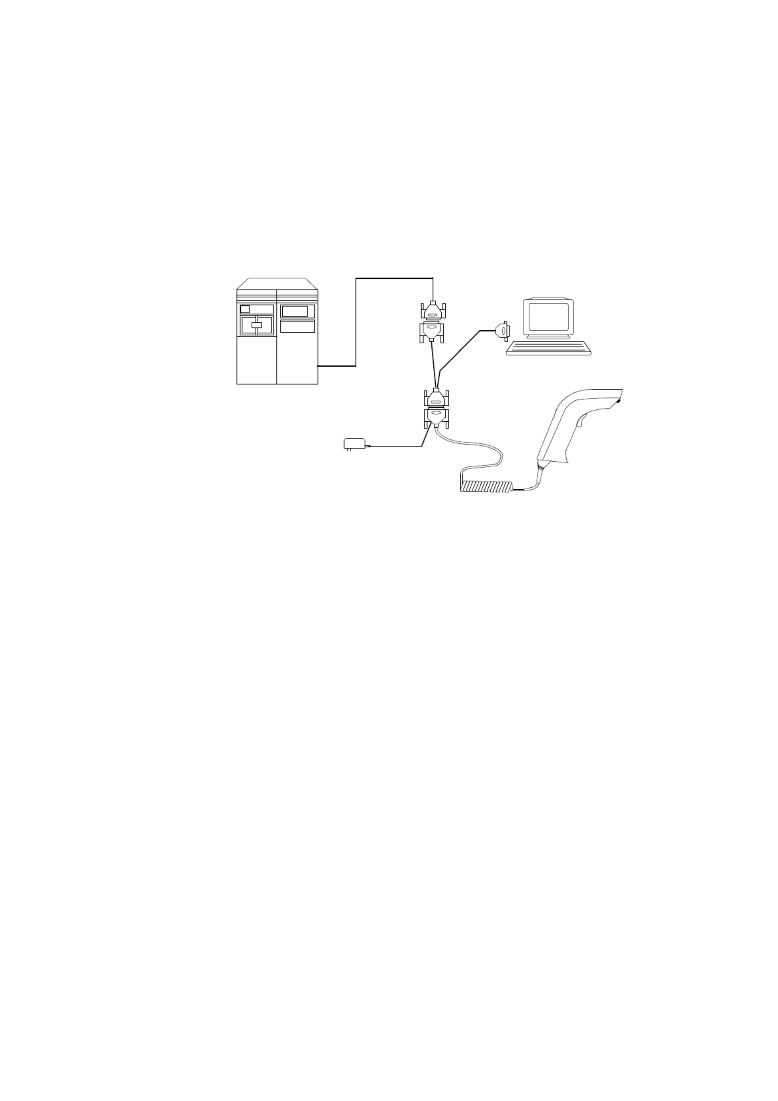
Chapter 3 RS232 Serial Interface
3.1 Installation
To use the scanner as a RS232 serial interface, a RS232 interface cable
and a power adapter are required. See Chapter 8 for cable pinout and
adapter specification. Figure 2 shows an installation diagram for your
reference.
Installation procedures:
1) Make sure the scanner’s cable has the right connector and pinout for
the RS232 port of the host device. If the pinout is different from
device, swapping pins is necessary to achieve proper communication.
2) If the host device has power output at RS232 interface port, the
scanner can be powered by connecting that power line to pin 9 of the
scanner connector. If there is no power at RS232 port, An AC
adapter is needed. Plug the adapter into the DB type connector at the
end of the interface cable.
Cash Register,
PC or other device.
Figure 2. Installed as a Serial Interface
AC adaptor
SCANNER
RS232 Connector
3) Plug the DB type connector of the interface cable into host’s RS232
port and power up the device.
4) When the scanner is powered, a long beep sound indicates the
scanner is ready to use.

Page 9
3.2 Understanding the Operating Parameters
Device Type
You will need to select the device type to “Serial Interface” from
Appendix A, Group 1 of Appendix D, or the following label.
Serial Interface
Baud Rate, Parity and Data Bit:
These parameters set the scanner’s communication protocol that must
be matched by the host. The default setting for the serial interface is
9600 baud rate, none parity, and 8 data bit.
* Baud Rate can be 300, 600, 1200, 2400, 4800, 9600, 19200, or 38400
bps.
* Parity can be even, odd, space, mark, or none.
* Data Bit can be 7 or 8 bit long.
The scanner may not support settings with Data Bit as 7 and Parity as
none combination. Such combination is treated as 7 data bits with
MARK parity.
Handshaking:
The scanner supports CTS/RTS handshaking as an option. The
hardware handshaking is supported on character-by-character basis.
During the communication, the scanner will stop sending data until the
CTS is valid within time specified by the Time Out parameter. During
this time-out waiting period:
-- If CTS is valid, communication resumes.
-- If CTS is not valid, the scanner sounds an error beep and discards
the current buffered data.

Page 10
BCC Character:
BCC check character is calculated for entire data stream by using
“Exclusive OR ” method. It is sent after data stream for data
verification.
Time Out:
You can adjust the Time Out duration for handshaking and ACK/NAK
protocol to fit applications.
3.3 Serial TTL
This scanner supports serial TTL interface which follows the RS232
communication data format but with TTL voltage output ranged from
0V to 5V.
Page 11
Chapter 4 Terminal Interface
4.1 Installation
To install the scanner as a terminal interface, you need a DB25 RS232
cable, a terminal wedge “Y” cable and an AC adapter. See Figure 3 for
reference.
Figure 3. Installing as a Terminal Wedge
Host
Terminal
AC adaptor
SCANNER
RS232 Cable
"Y" Cable
Original Cable
female
male
Installation procedures:
1) Power off the terminal and unplug the communication cable at
terminal side.
2) Install the interface cable as shown in Figure 3. The “Y” cable
provided in Figure 3 is for terminals with female connector on
communication port. If there is a male connector on your terminal,
you need a converter to change that male to female and another
converter to change the female to male on host connector.
3) When the scanner is powered, a long beep sound indicates that the
scanner is ready to use.

Page 12
4) If the scanner has not been configured yet, you need to select
“Terminal Wedge” device number from Appendix A, Group 1 of
Appendix D, or the following label.
Terminal Wedge
4.2 Understanding the Operating Parameters
Baud Rate, Parity and Data Bit:
These parameters set the scanner’s communication protocol which
must be matched the same setting by the host. The default setting for
the terminal interface is 9600 baud rate, none parity, and 8 data bit.
* Baud Rate can be 300, 600, 1200, 2400, 4800, 9600, 19200, or
38400 bps.
* Parity can be even, odd, space, mark, or none.
* Data Bit can be 7 or 8 bit long.
The scanner may not support settings with Data Bit as 7 and Parity as
none combination. Such combination is treated as 7 data bits with
MARK parity.
Data Direction:
This setting is only for the terminal wedge and corresponds to the
terminal communication mode. If the terminal has:
* "Full Duplex" mode, set the data direction to "Send to Host".
* "Half Duplex" mode, set to "Send to Host and Terminal".
* "Block" mode, set to "Send to Terminal".

Page 13
Chapter 5 Wand Emulation
5.1 Installation
Figure 4 shows how a wand emulation scanner is installed to a data
collection terminal. User needs to pay attention to the scanner pinout
that should be the same as specified by the terminal.
Figure 4. Installed as a Wand Emulation Scanner
SCANNER
5.2 Understanding the Operating Parameters
Code 39 Output:
When device number “07” is selected, the scanner is set as wand
emulation with Code 39 output. In this configuration, the scanner
always outputs data with Code 39 symbology no matter what
symbology of the label it scans. You may scan the following label if
this setting matched your application.
Code39 Wand
Emulation
Native Output:
When device number “26” is selected, the scanner is set to wand
emulation with native output. That means the scanner outputs data
with both the same contents and symbology as the label represents.

Page 14
Output of Wand Emulation: (Appendix D, 3)
Select one of the two choices for the polarity of data output:
* High level for bar (black) and low level for space (white).
* High level for space (white) and low level for bar (black).
Level Duration of Minimum Width: (Appendix D, 3)
Determine the minimum time duration for bar or space either 200 us or
600 us. Longer time means slower movement of the wand scanner.
Polarity of Idle: (Appendix D, 3)
Polarity of idle (without scanning) can be selected either low or high.

Page 15
Chapter 6 Setup
The scanner interface can be configured to fit the user's specific
application. All configuration parameters are stored in a non-volatile
memory, which is retained even if power is lost.
6.1 Bar Code Menu Setup
The setup menu in Appendix D contains eight groups:
* Group 1: Device selection.
* Group 2: Beep and delay.
* Group 3: Keyboard and Wand Emulation.
* Group 4: RS-232 Settings
* Group 5: Scanner port.
* Group 7: Code 39, I 2 of 5, S 2 of 5 and Code 32.
* Group 8: Code 128, Code 93, Code 11, Codabar, and MSI.
* Group 9: UPC/EAN, and Delta Distance Code.
* Group 10: Data Editing.
* Group 11: Dump setup.
6.1.1 Setup Procedures:
For most parameters, proceed the following steps for the setting:
1) Locate a group that contains the parameter to be changed.
2) Scan the "Enter Group #" label to enter setup mode. The green
LED on the scanner will flash to indicate that setup is in progress.
3) Scan the label (on right hand side) representing the parameter to
be changed.(For example, B1 label)
4) Scan the labels (number) representing the desired parameter value.
(For example, 05, scan “0” and “5” labels.)
5) Repeat step 3 and 4, if necessary, to change the parameters in the
same group.
6) Scan "Exit" label to end the group setup. The scanner will make
two beeps to end the setup.

Page 16
6.1.2 Bar Code Length Setting:
The following example illustrates how to set Code 39 with a minimum
length of 5 and a maximum length of 20:
* Scan “Enter Group 5”.
* Scan “F1” to select Code 39.
* Scan “MIN LENGTH” to enter minimum length setting.
* Scan “0” and “5” to select length 5.
* Scan “MIN LENGTH” to end minimum length setting.
* Scan “MAX LENGTH” to enter maximum length setting.
* Scan “2” and “0” to select length 20.
* Scan “MAX LENGTH” to end maximum length setting.
* Scan “Exit” to end setup.
6.1.3 Code ID Setting:
Each bar code symbology supported by the scanner has a default ID
character defined as below: (If you don’t know what is the label that
you’re scanning, you may use this feature to identify.)
Symbology Pre-Defined
UPC-A A
UPC-E E
EAN-13 F
EAN-8 FF
I 2 of 5 I
S 2 of 5 H
Code 39 M
Codabar N
Code 93 L
Code 128 K
UCC/EAN128 ]C1
MSI O
Code 32 T
Delta Code D
Plessey Code P
Label Code IV,V B
China Postal Code C

Page 17
Those ID characters can be redefined through setup menu. The
following example shows how to set Code 93 with ID ‘O’ and Code
128 without ID:
* Scan “Enter Group 3”.
* Scan “D2” to select Code ID.
* Scan “1” for "Yes".
* Scan “D3” to define IDs.
* Scan “0” and “9” for selecting Code 93.
* Scan “O” from Full ASCII Table for new ID.
* Scan “0” and "8" to select Code 128.
* Scan “NULL” character from Full ASCII Table for none ID.
* Scan “Exit” to end setup.
6.1.4 Preamble(Prefix) and Postamble(Suffix):
Preamble, the scanner adds the start of text characters before the input
data. Postamble, the scanner adds end of text characters after the input
data. The following is an example to set ‘STX’ as preamble and ‘ETX’
as postamble:
* Scan “Enter Group 3”.
* Scan “PP” to start preamble setting.
* Scan ‘STX’ character from Full ASCII Table.
* Scan “PP” to end preamble setting.
* Scan “OO” to start postamble setting.
* Scan ‘ETX’ from Full ASCII Table.
* Scan “OO” to end postamble setting.
* Scan “Exit”.
6.1.5 Predefined Labels
The scanner provides three special labels encoded as “/FY”, “/FZ” and
“/F-” in Code 39 format. The output from these labels can be defined
through the setup menu. The definition of the labels share the same
space with “Edit Formula definition”(See “Output Data Editing”), so
you can only use either one of the function.
Label 0 Label 1 Label 2
/ F Y / FZ / F-

Page 18
Here is an example how to define the output of “Label 0” as “START”,
“Label 1” as “ACCEPT” and “Label 2” as “END”:
* Scan “Enter Group 3”
* Scan “B7”
* Scan “0” to define “Label 0”
* Scan “S”, “T”, “A”, “R” and “T” from Full ASCII chart
* Scan “B7” to end “Label 0”
* Scan “1” to define “Label 1”
* Scan “A”, “C”, “C”, “E”, “P” and “T” from FULL ASCII chart
* Scan “B7” to end “Label 1”
* Scan “2” to define “Label 2”
* Scan “E”, “N” and “D” from Full ASCII chart
* Scan “B7” to end “Label 2”
* Scan “Exit” to quit setup
After the programming, scan “Label 0”, “Label 1” and “Label 2” listed
above will have output of “START”, “ACCEPT” and “END”
respectively. The characters defined in these labels can be ASCII
characters or Function keys.
To eliminate the definition of “Label 1”, do the following:
* Scan “Enter Group 3”
* Scan “B7”
* Scan “1” to choose “Label 1”
* Scan “B7” to end
* Scan “Exit” to exit setup
There is only total 24 characters space available for defining these
three labels. If one of the labels has been defined the output with 24
characters, the other two labels can not be defined further.
6.2 Quick Setup
Appendix A has a quick setup chart which gives you one-label-for-one-
function convenience to setup the scanner. To setup the scanner, locate
the label with the function you want and scan that label.
6.3 Batch Setup
If you need to configure more than one scanner, you may duplicate the
settings of the scanner (master) to the others. You can do this by
producing a set of custom setup labels derived from the master scanner
and scanning these labels configuring the other scanners.

Page 20
The following issues should be observed:
• The sequence of the strings that the scanner dumped is important. You
have to print the bar code labels and scan them in the same sequence as
the one that the scanner dumped.
• When you scan the batch setup labels to configure a scanner, the
previous settings on that scanner are reset to default and then replaced
by the settings contained in the batch labels.
• Only the settings that are different from the default values will be
dumped. So the number of labels produced depends on how many
settings being changed compare to the factory default setting.
• The settings can be dumped to a PC or terminal only if that PC or
terminal matches the type defined by Device Type of the scanner. The
previous example of “Keyboardless Wedge” as Device Type is
equivalent to a PC/AT interface, so you can not dump that settings to a
system which dose not support a PC/AT keyboard interface.
The following label let you dump the settings to a PC/AT regardless
what kind of device has been chosen on the scanner.
Dump Settings On PC/AT
• You can adjust the length of the dumped strings by combining multiple
strings into one or breaking one string into multiple strings. The
following strings have the same effect as the dumped string listed above:
...I800C06D51DJ8080
80A0O7C005354415254.
You can not delete any character from or add any character into the
strings and the first three characters (“...”) must present in the first
string.
• All characters in dumped strings are in upper case. If you see lowercase
characters in dumped strings, change them to upper case.

Page 22
Formular
Qualifier Modifier
Input ID Input ID[Length] [Match] [Length] [Match] [Match] [Match]
...
A-String: String to be added.
O-String: Modified original data.
[] : Optional.
Figure 7.1 Formula Structure
7.3. Programming
7.3.1. Programming Sequence:
Each Formula is entered into the Reader by the following sequence:
Input_ID>>Length>>Match>>A-String>>O-String O-String>>...>>
>>Enter
A Formula starts with Input_ID and ends with “Enter”(a label in
programming sheet). If a field is optional and missing, the next one in
the sequence can be entered. But “Enter” must be the last input of a
formula.
7.3.2. Preparation
To start the data editing, the following barcode sheets are needed:
-- Programming Sheet.( Setup Sheet in Appendix D).
-- Full ASCII Sheet (Appendix E).
-- Function Code Sheet (Appendix B or C).
Before programming Data Editing, you should know the format of the
original data record that may be altered by the setup groups.

Page 24
b) String Parameters
A string is a set of characters, wild characters, or sequence of
adjacent characters enclosed in double quotation marks, which are
on the Programming Sheet. For example:
" "A* #B
Here * and # are wild characters on the setup sheet.
7.4. Qualifier
There are three conditional fields in the Qualifier:
Input ID, Length and Match.
7.4.1. Input ID
Format:
IN_ID, , ,ID1, ... IDi
Input ID is required and the original data record must correspond to
Input ID of a formula in order to be processed.
ID1 to IDi are represented by digits. The following Input IDs are
available:
0 = Code 39 Full ASCII
1 = Code 39 Standard
2 = EAN 13
3 = EAN 8
4 = UPC A
5 = UPC E
6 = I 2 of 5
7 = Codabar
8 = Code 128
9 = Code 93
10 = S 2 of 5
11 = MSI
19 = UCC/EAN128
28 = All Inputs
There is no limitation on the number of IDs to be defined.
Example:
IN_ID, , ,0 11
means the original data can be Code 39 or MSI.

Page 25
7.4.2. Length:
Format:
LEN, , ,Min Max
Length field consists of two length parameters: minimum length (Min)
and maximum length (Max). When defined, a formula will be
performed if the length of the original data falls between MIN and
MAX
When missing, the following fields of current Formula are always
processed.
Example:
LEN, , ,9 48
means the length of original data must be within 9 and 48.
7.4.3. Match
Format:
MATCH, , , , , , , , P0 " "C0 P1 " "C1 ... Pn " "Cn
a pair of Pn and Cn forms a Match field (n indicates a sequential
integer number). To define a Match field, two parameters are required.
The first is character position (Pn) and the second is a string (Cn).
Character position means the number of characters, counting from the
first character to the one to be positioned in the data record.
For example, in the following data
BARCODE
'B' has position 1.
'A' has position 2.
...
'E' has position 7.
When Match field is defined, the original data string starts at the
position specified by the first parameter P and will be compared with
string "C". If the match is identical, processing of current Formula
continues.
The position parameter P could be a wild character * for any position
or # for the last position in the original data. If # is used,
#-N
is valid. Here N is a digit parameter.
The string parameter C can include * for any digit or # for any letter.
Examples:
MATCH, , , , ,3" "AB # " "?

Page 26
Checks if the original data has 'A' at position 3, 'B' at position '4' and
last character is '?'.
MATCH , , , 10 " " *A*
Checks if the original data includes a string with a digit as first
character and "A*" followed at position 10.
7.5. Modifier
Modifier has two types of fields: A-String and O-String to define the
output contents.
7.5.1. A-String
Format:
" "abc...
'a', 'b' and 'c' in the string can be any character.
A-String defines a string of characters to be added to the output. For
example, if the original data is:
BCD
and output string is BarCoDe
"ar", 'o' and 'e' in output string are added strings and can be defined by
A-Strings.
Note: If '*' on Programming Sheet are included in A-String, one
interblock delay defined by Group 2 will be inserted.
7.5.2. O-String
Format:
O-STR , , , P N
O-String always applies to the original data. It contains two
parameters. The first is position parameter (P) that specifies the start
output position in the original data. Parameter N tells how many
characters will be included beginning from P.
Example:
Original data is:Barcode
Then
O-Str ,,, 4 4
Gives output as
code
Note:
-- N can be '#' for all remaining characters from P.
-- If P greater than the length of original data, the O-String will be
skipped.

Page 27
-- If N greater than the number of remaining characters counting from
P, the remaining characters are included as valid.
7.6. Examples
7.6.1. Example 1
If the original data is Code 39 and content is "AA", output "ABC
Company", and otherwise output the original data as it is.
IN_ID, , , , , , , , ,0LEN 2 2 MATCH 1" "AA " "ABC company Enter
IN_ID, , , , ,19 O-STR 1# Enter
7.6.2. Example 2
If the original data is Code 128 and logically divided into:
-- First six characters are personal ID,
-- Other characters are person's name.
The output will be:
-- Personal ID first,
-- A 'CR' character,
-- Two interblock delay,
-- Name,
-- A 'CR' character.
The Formula will be:
IN_ID, , , , , , , , , ,8O-STR 1 6 " "<CR>** O-STR 7# " "<CR> Enter
<CR> is a Carriage Return character scanned from Full ASCII Chart.
7.7. Advanced Features
The O-String has the format:
O-STR, , ,P N
Both parameters of O-String mentioned above are numbers. But both
parameters can be specified as strings. If N is a string, it becomes a
position and the meaning of O-String will be "Output from position P
to position N".
If P is defined as:
" "ab...ik
a, b, , i and k can be any character, the position will be evaluated as
-- Start from the first position of the original string and search
character 'a'.
-- From the position next to 'a' in original data, search for 'b'.
-- ....

Page 28
-- From the position next to 'i', search for k.
-- If above searches are all found, the result of the parameter will be the
position where 'k' is located.
If N is a string, the position evaluation of N is the same as P except that
the searching position is starting from P+1.
For both P and N, if string is defined, a value can be added to or
subtracted from the position. That following O-Strings:
" "ab...ik +M,
And
" "ab...ik -M,
Are meaningful. M is a integer number.
Example:
Suppose the following is a message to be modified:
%B012345678901234^ABEL/STEVE L MGR ^90010129999999?
in this message:
"%" is start sentinel.
"012345678901234" is account number.
"^" is a separator
6. "ABEL" is surname.
"/" is a separator.
"STEVE" is first name.
"L" is initial.
"MGR" is title
"^" is a separator.
"9001" is expiration date.
"?" is end sentinel.
The output sequence desired is:
Surname, First Name [CR] Account Number [CR] Expiration Date [CR]
The formula input will be:
IN_ID, , , , , , , , , ,0O-STR " "^ +1 " "/ -1 "," O-STR " "/ +1 " "<SP> -1 " "<CR>
O-STR O-STR, , , ,3" "^ -1 " "<CR> , , , ," "^^ +1 4 " "<CR> Enter
Here <SP> is Space character and <CR> is Carriage Return character.
The output of above input will be
ABEL,STEVE[CR]
012345678901234[CR]
9001[CR]

Page 29
Chapter 8 Pin Assignment and Specification
8.1 Pin Assignments
The modular connector
located at the bottom of
the scanner handle has
the pin numbering as
shown at the right
picture
8.1.1. Keyboard Interface
The next table shows the modular connector pinout for keyboard
interface:
Pin Number Signal
1 Not Used
2 VCC(+5V, output)
3 DET
4 GND
5 Terminal Data
6 Terminal Clock
7 Power Input (+5V)
8 Keyboard Clock
9 Keyboard Data
10 Not Used
Note: DET signal is bi-directional I/O pin and for internal use only.
As keyboard interface, there are two other connectors on the interface
cable. The connector type and pinout differ from terminal to terminal
and are not listed here.
8.1.2. RS232 Interface
The scanner supports TTL RS232 at modular connector and standard
RS232 after the interface cable is attached.
110
Modular Connector ( Front View)

Page 30
TTL RS232 Interface:
The following table shows pinout for TTL RS232 interface at modular
connector:
Pin Number Signal
1 Not Used
2 VCC(+5V, output)
3 DET
4 GND
5 RXD
6 TXD
7 Power Input (+5V)
8 CTS
9 RTS
10 Not Used
Note:
(1) DET signal is bi-directional I/O pin and for internal use only.
(2) CTS and RXD are input signals and take 0V to 5V only. If the
scanner is used to interface with a standard RS232 port, those
signals should not be connected.
Standard RS232 Interface:
To support standard RS232 interface, an RS232 adapter cable from the
manufacture must be used. This cable is a special one and can not be
replaced by the others. One end of that cable which has RS232 signal
presented is a DB25 or DB9 female connector and has following
pinout:
DB25 Female (Front View)
1
13
14
25
Pin
Number
Signal
2 RXD
3 TXD
14 CTS
16 RTS
7 GND
25 Power Input(+5V±5%)

Page 31
DB9 Female (Front View)
1
5
6
9
Pin
Number
Signal
2 TXD
3 RXD
5 GND
7 CTS
8 RTS
9 VCC
8.1.3. Terminal Interface
To use the scanner as a terminal Interface, an “Y” cable is used. One
end of this cable is connected to the standard RS232 adapter cable
shown above and the other two are for the host and terminal.
Host Side connector
The connector for the host is a DB25 female and has following pinout:
DB25 Female (Front View)
113
14
25
Pin
Number
Signal
2 TXD
3 RXD
4 RTS
5 CTS
6 DSR
7 GND
8 CD
20 DTR

Page 32
Terminal Side connector
The connector for the terminal is a DB25 male and has following
pinout:
DB25 Male (Front View)
113
14 25
Pin
Number
Signal
2 RXD
3 TXD
4 CTS
5 RTS
6 DTR
7 GND
8 CD
20 DSR
8.1.4. Wand Emulation
The pinout on modular connector at the bottom of the scanner is:
Pin Number Signal
1 Not Used
2 VCC(+5V, output)
3 Not Used
4 GND
5 Not Used
6 Bar Code Output
7Power Input(+5V±5%) DC
8 Not Used
9 Not Used
10 Not Used

Page 33
On the other end of the wand emulation cable is a squeeze released
DB9 female connector. The pinout for this connector is:
Pin Number Signal
1 Not Used
2 Bar Code Output
3 Not Used
4 Not Used
5 Not Used
6 Not Used
7 GND
8 Not Used
9 Power Input
8.2 Specification
* Power:
- Operating Voltage: +5V ±5% DC.
* Temperature:
- Operating: 0°C to 50°C (32°F to 122°F)
- Storage: -20 C (-4°C to 70° °F to 158°F)
* Humidity:
- 0% to 95% relative humidity.

Appendix A. Quick Setup Sheet
Page A.1
Device Type
PC AT[PS/2]
PS/2
Macintosh
USB
IBM Terminal
Keyboardless
Code39 Wand
Emulation
Serial Interface
Terminal Wedge
Scanner Mode
Trigger
Flash
UPC-E
Default
Cut Leading Digit
Send Check Digit
UPC-A Conversion
Beep
None
Medium
Terminator
Enter
Field Exit
Scan Code
U.S.
Alt Key

Appendix A. Quick Setup Sheet
Page A.2
EAN-8
Default
Cut Leading Digit
Cut Check Digit
EAN-13
Default
Cut Leading Digit
Cut Check Digit
ISBN Conversion
Character Delay
1 ms
20 ms
Code ID
No
Yes
UPC-A
Default
Cut Leading Digit
Cut Check Digit
Supplement Code
No
Yes
Menu Setup
Enable / Disable
Display Version
Display Version
Factory Default
Factory Default

Page B.1
Appendix B. Function Codes
Function Codes for PC
F1 (%VA)
F3 (%VC)
F5 (%VE)
F7 (%VG)
F9 (%VI)
F11 (%VK)
Cursor Right (/FC)
Cursor Up (/FE)
PgUp (/FG)
TAB (/FI)
Esc (/FK)
Right Ctrl (/FO)
Shift Make (/FP)
Ctrl Make (/FQ)
Alt Make (/FR)
Del (/FX)
F2 (%VB)
F4 (%VD)
F6 (%VF)
F8 (%VH)
F10 (%VJ)
F12 (%VL)
Cursor Left (/FD)
Cursor Down (/FF)
PgDn (/FH)
Back Tab (/FJ)
Left Enter (/FL)
Right Enter (/FM)
Ins (/FW)
Shift Break (/FS)
Ctrl Break (/FT)
Alt Break (/FU)

Page B.2
Function Codes for Macintosh
F1 (%VA)
F2 (%VB)
F3 (%VC)
F4 (%VD)
F5 (%VE)
F6 (%VF)
F7 (%VG)
F8 (%VH)
F9 (%VI)
F10 (%VJ)
F11 (%VK)
F12 (%VL)
F13 (%VM)
F14 (%VN)
F15 (%VO)
Cursor Left (/FD)
Cursor Right (/FC)
Cursor Down (/FF)
Cursor Up (/FE)
Page down (/FH)
Page up (/FG)
Ins (/FJ)
Tab (/FI)
Enter (/FL)
Esc (/FK)
Return (/FM)
Option Make (%VP)
Option Break (%VQ)
Control Make (%VR)
Control Break (%VS)
Shift Make (%VT)
Shift Break (%VU)
Apple Make (%VV)
Apple Break (%VW)

Page C.1
Appendix C. Function Codes for IBM Terminals
F1 (%VA)
F3 (%VC)
F5 (%VE)
F7 (%VG)
F9 (%VI)
F11 (%VK)
F13 (%VM)
F15 (%VO)
F17 (%VQ)
F19 (%VS)
F21 (%VU)
F23 (%VW)
Home (/FA)
TAB (/FI)
Return (/FM)
Field + (/FP)
Clear(/FR)
F2 (%VB)
F4 (%VD)
F6 (%VF)
F8 (%VH)
F10 (%VJ)
F12 (%VL)
F14 (%VN)
F16 (%VP)
F18 (%VR)
F20 (%VT)
F22 (%VV)
F24 (%VX)
End (/FB)
Enter (/FL)
Field Exit (/FO)
Field - (/FQ)
Reset (/FV)

Page D.1
Appendix D. Setup Menu
D.1 Device Selection and Default:
Enter Group 1 Group Default
Device ID Device Type .
0
1
2
3
4
5
6
7
8
9
00 – IBM PC/XT
01 – IBM PC/AT, PS/2 MOD 40, 60, 80, USB etc.
02 – IBM PS/2 MOD30(8086) 25, 56, 70, 90
08 – IBM 3196/3197
09 – IBM 3476/3477
10 – IBM 3191/3192/3270PC
11 – IBM 3486/3487/3488
13 – IBM /3471/3472(/3179)
15 – IBM 3180
17 – IBM 3151
19 – IBM 5550-5P
20 – IBM 5550-6P
06 – Keyboardless Wedge(PC/AT)
03 – Macintosh (ADB Port)
04 – Serial Wedge
35 – Serial TTL inverted
25 – Terminal Wedge
26 – Wand emulation (Native Output)
07 – Wand emulation (with Code 39 output)
Factory Default
Exit

Page D.2
D.2 Beeps and Delays
Enter Group 2 Group Default
0
1
2
3
4
5
6
7
8
9
Beep Tone:
0 -- None
1 -- Low
2 -- Medium
3 -- High
4 -- Low to High
5 -- High to Low
Interblock Delay:
0 -- 0 ms
1 -- 10 ms
2 -- 50 ms
3 -- 100 ms
4 -- 500 ms
5 -- 1 seconds
6 -- 3 seconds
7 -- 5 seconds
Intercharacter Delay:
0 -- 0 ms
1 -- 1 ms
2 -- 2 ms
3 -- 5 ms
4 -- 10 ms
5 -- 30 ms
6 -- 500 ms
7 -- 100 ms
MPU Idle Status
0 – MPU sleep mode
1 – MPU watch mode
2 – MPU stand by mode
Here1/2 selections are for power saving mode. If you
select this selection, the scanner may loss some other
benefits like Caps Lock Tracing function.
A1
A2
A3
A4
Exit

Page D.3
D.3 Keyboard Wedge Settings
Enter Group 3 Group Default
0
1
2
3
4
5
6
7
8
9
Function Code:
0 -- Off
1 -- ON
Caps-Lock:
0 – Auto Trace(PC/XT,AT)
1 – Lower Case
2 – Upper Case
Language (For PC/XT/AT):
0-U.S. 5-Norwegian :-Danish
1-U.K. 6-Italian
2-Swiss 7-German
3-Swedish 8-French
4-Spanish 9-Alt Key Mode
Output of Wand Emulation:
0—Bar with High/Space with Low
1—Bar with Low/Space with High
Level Duration of Mini Width:
0—200us
1—600us
Polarity of Idle Condition:
0—Low
1—High
Pre-define Label:
0—Label 0 1—Label 1 2—Label 2
(See “Pre-defined label” section for detail)
Use number keypad digits:
0—Disable 1—Enable
B1
B2
B3
B4
B5
B6
B7
B8
Exit
Product specificaties
| Merk: | Unitech |
| Categorie: | Barcode lezer |
| Model: | MS210 |
| Kleur van het product: | Beige |
| Gewicht: | 124.7 g |
| Bluetooth: | Nee |
| Meegeleverde kabels: | USB |
| Certificering: | EMI, FCC A, CE |
| Type beeldsensor: | CCD |
| Ingangsspanning: | 5 V |
| Temperatuur bij opslag: | -20 - 60 °C |
| Golflengte: | 660 nm |
| Stroomverbruik: | 85 mA |
| Standaard interfaces: | USB |
| Afmetingen (B x D x H): | 88 x 80 x 188 mm |
| Bedrijfstemperatuur (T-T): | 0 - 50 °C |
| Relatieve vochtigheid in bedrijf (V-V): | 20 - 85 procent |
| Lichtbron: | LED |
| Lees-snelheid (max): | 90 lezingen/s |
| Werkafstand: | 80 mm |
| Decoding standaarden: | Code 39, ASCII, Codabar, UPC/EAN, UCC/EAN 128, Interleaved 2 - 5, MSI/Plessy, Standard 2 - 5, Toshiba Code, Label code IV / V, Delta Distance, Code 93, Code 128, Code 32 |
Heb je hulp nodig?
Als je hulp nodig hebt met Unitech MS210 stel dan hieronder een vraag en andere gebruikers zullen je antwoorden
Handleiding Barcode lezer Unitech

26 Februari 2025
20 Februari 2025
20 Februari 2025
20 Februari 2025
27 Februari 2024
27 Februari 2024
27 Februari 2024
27 Februari 2024
27 Februari 2024
27 Februari 2024
Handleiding Barcode lezer
- Barcode lezer Casio
- Barcode lezer Garmin
- Barcode lezer Honeywell
- Barcode lezer Motorola
- Barcode lezer Bluebird
- Barcode lezer Datalogic
- Barcode lezer DeLock
- Barcode lezer Digitus
- Barcode lezer ID-Tech
- Barcode lezer Intermec
- Barcode lezer Konig
- Barcode lezer Manhattan
- Barcode lezer Nedis
- Barcode lezer Palm
- Barcode lezer Renkforce
- Barcode lezer Zebra
- Barcode lezer Olympia
- Barcode lezer Trimble
- Barcode lezer Steren
- Barcode lezer Argox
- Barcode lezer CipherLab
- Barcode lezer Metapace
- Barcode lezer Hamlet
- Barcode lezer Adesso
- Barcode lezer Deltaco
- Barcode lezer Nilox
- Barcode lezer Approx
- Barcode lezer Brady
- Barcode lezer GoDEX
- Barcode lezer EC Line
- Barcode lezer ELO
- Barcode lezer IFM
- Barcode lezer IC Intracom
- Barcode lezer POSline
- Barcode lezer Newland
- Barcode lezer Posiflex
- Barcode lezer Baracoda
- Barcode lezer Datamax-O'neil
- Barcode lezer Cypress
- Barcode lezer DENSO
- Barcode lezer Socket Mobile
- Barcode lezer QUIO
- Barcode lezer Tecno
- Barcode lezer ZBA
- Barcode lezer Code Corporation
- Barcode lezer Qoltec
- Barcode lezer Wasp
- Barcode lezer Vultech
- Barcode lezer Mach Power
- Barcode lezer Psion
- Barcode lezer Koamtac
- Barcode lezer Opticon
- Barcode lezer Atlantis Land
- Barcode lezer Code
- Barcode lezer Qian
- Barcode lezer Cognex
Nieuwste handleidingen voor Barcode lezer
26 Februari 2025
26 Februari 2025

25 Februari 2025
14 Februari 2025
5 Februari 2025
27 Januari 2025
14 Januari 2025
14 Januari 2025
14 Januari 2025
5 December 2024