Sony DVW-970P Handleiding
Lees hieronder de 📖 handleiding in het Nederlandse voor Sony DVW-970P (164 pagina's) in de categorie Camcorder. Deze handleiding was nuttig voor 47 personen en werd door 2 gebruikers gemiddeld met 4.5 sterren beoordeeld
Pagina 1/164

DIGITAL CAMCORDER
DVW-970/970P
OPERATION MANUAL [English]
1st Edition (Revised 2)
T M
The supplied CD-ROM includes operation manuals for the DVW-970/
970P Digital Camcorder (English, Japanese, French, German, Italian,
Spanish and Chinese versions) in PDF format.
For more details, see “1-4 Using the CD-ROM Manual” on page 15.

2
To reduce the risk of fire or electric shock,
do not expose this apparatus to rain or
moisture.
To avoid electrical shock, do not open the
cabinet. Refer servicing to qualified
personnel only.
For the customers in the USA
This equipment has been tested and found to comply with the
limits for a Class B digital device, pursuant to Part 15 of the
FCC Rules. These limits are designed to provide reasonable
protection against harmful interference in a residential
installation. This equipment generates, uses, and can radiate
radio frequency energy and, if not installed and used in
accordance with the instructions, may cause harmful
interference to radio communications. However, there is no
guarantee that interference will not occur in a particular
installation. If this equipment does cause harmful interference
to radio or television reception, which can be determined by
turning the equipment off and on, the user is encouraged to try
to correct the interference by one or more of the following
measures:
—Reorient or relocate the receiving antenna.
—Increase the separation between the equipment and
receiver.
—Connect the equipment into an outlet on a circuit different
from that to which the receiver is connected.
—Consult the dealer or an experienced radio/TV technician
for help.
You are cautioned that any changes or modifications not
expressly approved in this manual could void your authority to
operate this equipment.
All interface cables used to connect peripherals must be
shielded in order to comply with the limits for a digital device
pursuant to Subpart B of Part 15 of FCC Rules.
For the customers in the USA and Canada
RECYCLING LITHIUM-ION BATTERIES
Lithium-Ion batteries are recyclable.
You can help preserve our environment by returning your used
rechargeable batteries to the collection and recycling location
nearest you.
For more information regarding recycling of rechargeable
batteries, call toll free 1-800-822-8837, or visit
http://www.rbrc.org/
Caution: Do not handle damaged or leaking lithium-ion
batteries.
For the State of California, USA only
Perchlorate Material - special handling may apply, See
www.dtsc.ca.gov/hazardouswaste/perchlorate
Perchlorate Material : Lithium battery contains perchlorate.
For the customers in Europe
This product with the CE marking complies with the EMC
Directive (89/336/EEC) issued by the Commission of the
European Community.
Compliance with this directive implies conformity to the
following European standards:
• EN55103-1: Electromagnetic Interference (Emission)
• EN55103-2: Electromagnetic Susceptibility (Immunity)
This product is intended for use in the following
Electromagnetic Environment(s):
E1 (residential), E2 (commercial and light industrial), E3
(urban outdoors) and E4 (controlled EMC environment, ex. TV
studio).
Voor de Klanten in Nederland
• Gooi de batterij niet weg maar lever deze in als klein
chemisch afval (KCA).
• Dit apparaat bevat een vast ingebouwde batterij die niet
vervangen hoeft te worden tijdens de levensduur van het
apparaat.
• Raadpleeg uw leverancier indien de batterij toch vervangen
moet worden. De batterij mag alleen vervangen worden door
vakbekwaam servicepersoneel.
• Lever het apparaat aan het einde van de levensduur in voor
recycling, de batterij zal dan op correcte wijze verwerkt
worden.
For the customers in Taiwan only
WARNING

3
Afin de réduire les risques d’incendie ou
d’électrocution, ne pas exposer cet
appareil à la pluie ou à l’humidité.
Afin d’écarter tout risque d’électrocution,
garder le coffret fermé. Ne confier
l’entretien de l’appareil qu’à un personnel
qualifié.
Pour les utilisateurs aux Etats-Unis et au Canada.
RECYCLAGE DES ACCUMULATEURS AUX IONS DE
LITHIUM
Les accumulateurs aux ions de lithium sont recyclables.
Vous pouvez contribuer à préserver l’environnement en
rapportant les piles usées dans un point de collection et
recyclage le plus proche.
Pour plus d’informations sur le recyclage des accumulateurs,
téléphonez le numéro gratuit
1-800-822-8837 (Etats-Unis et Canada uniquement), ou
visitez http://www.rbrc.org/
Avertissment : Ne pas utiliser des accumulateurs aux ions de
lithium qui sont endommagées ou qui fuient.
Pour les clients européens
Ce produit portant la marque CE est conforme à la Directive
sur la compatibilité électromagnétique (EMC) (89/336/CEE)
émise par la Commission de la Communauté européenne.
La conformité à cette directive implique la conformité aux
normes européennes suivantes :
• EN55103-1 : Interférences électromagnétiques (émission)
• EN55103-2 : Sensibilité électromagnétique (immunité)
Ce produit est prévu pour être utilisé dans les environnements
électromagnétiques suivants :
E1 (résidentiel), E2 (commercial et industrie légère),
E3 (urbain extérieur) et E4 (environnement EMC contrôlé, ex.
studio de télévision).
Um die Gefahr von Bränden oder
elektrischen Schlägen zu verringern, darf
dieses Gerät nicht Regen oder Feuchtigkeit
ausgesetzt werden.
Um einen elektrischen Schlag zu
vermeiden, darf das Gehäuse nicht
geöffnet werden. Überlassen Sie
Wartungsarbeiten stets nur qualifiziertem
Fachpersonal.
Für Kunden in Europa
Dieses Produkt besitzt die CE-Kennzeichnung und erfüllt die
EMV-Richtlinie (89/336/EWG) der EG-Kommission.
Angewandte Normen:
• EN55103-1: Elektromagnetische Verträglichkeit
(Störaussendung)
• EN55103-2: Elektromagnetische Verträglichkeit
(Störfestigkeit),
für die folgenden elektromagnetischen Umgebungen:
E1 (Wohnbereich), E2 (kommerzieller und in beschränktem
Maße industrieller Bereich), E3 (Stadtbereich im Freien) und
E4 (kontrollierter EMV-Bereich, z.B. Fernsehstudio).
Für Kunden in Deutschland
Entsorgungshinweis: Bitte werfen Sie nur entladene Batterien
in die Sammelboxen beim Handel oder den Kommunen.
Entladen sind Batterien in der Regel dann, wenn das Gerät
abschaltet und signalisiert „Batterie leer“ oder nach längerer
Gebrauchsdauer der Batterien „nicht mehr einwandfrei
funktioniert“. Um sicherzugehen, kleben Sie die Batteriepole
z.B. mit einem Klebestreifen ab oder geben Sie die Batterien
einzeln in einen Plastikbeutel.
AVERTISSEMENT WARNUNG

4
Per ridurre il rischio di incendi o scosse
elettriche, non esporre questo apparato
alla pioggia o all’umidità.
Per evitare scosse elettriche, non aprire
l’involucro. Per l’assistenza rivolgersi
unicamente a personale qualificato.
Per i clienti in Europa
Questo prodotto recante il marchio CE è conforme sia alla
direttiva sulla compatibilità elettromagnetica (EMC) (89/336/
CEE) emesse dalla Commissione della Comunità Europea.
La conformità a queste direttive implica la conformità alle
seguenti normative europee:
• EN55103-1: Interferenza elettromagnetica (Emissione)
• EN55103-2: Sensibilità ai disturbi elettromagnetici
(Immunità)
Questo prodotto è destinato all’uso nei seguenti ambienti
elettromagnetici:
E1 (residenziali), E2 (commerciali e industriali leggeri), E3
(esterni urbani) e E4 (ambienti EMC controllati, ad esempio
studi televisivi).
Para reducir el riesgo de electrocución, no
exponga este aparato a la lluvia ni a la
humedad.
Para evitar descargas eléctricas, no abra el
aparato. Solicite asistencia técnica
únicamente a personal especializado.
Para clientes de los EE UU y CANADÁ
RECYCLADO DE BATERIAS DE IONES DE LITIO
Las baterías de iones de litio son reciclables.
Useted podrá ayudar a conservar el medio ambiente
devolviendo las baterías usadas al punto de reciclaje mas
cercano.
Para más información sobre el reciclado de baterías, llame al
número gratuito
1-800-822-8837, o visite http://www.rbrc.org/
Precaución: No utilice baterías de iones de litio dañadas o con
fugas.
Para los clientes de Europa
Este producto cumple con las directivas de compatibilidad
electromagnética (89/336/CEE) de la Comisión Europea.
El cumplimiento de estas directivas implica la conformidad
con los siguientes estándares europeos:
• EN55103-1: Interferencia electromagnética (Emisión)
• EN55103-2: Susceptibilidad electromagnética (Inmunidad)
Este producto está ha sido diseñado para utilizarse en los
entornos electromagnéticos siguientes:
E1 (zona residencial), E2 (zona comercial e industrial ligera),
E3 (exteriores urbanos), y E4 (entorno con EMC controlada,
p. ej., estudio de televisión).
ATTENZIONE ADVERTENCIA

5

6Table of Contents
Table of Contents
Chapter 1 Overview
1-1 Features ......................................................................... 11
1-1-1 Camera Features .............................................................11
1-1-2 VTR Features ..................................................................12
1-1-3 Other Features.................................................................12
1-2 Example of System Configuration .............................. 14
1-3 Precautions ................................................................... 15
1-4 Using the CD-ROM Manual .......................................... 15
1-4-1 Preparations ....................................................................15
1-4-2 Reading the CD-ROM Manual .......................................15
Chapter 2 Locations and Functions of Parts and Controls
2-1 Power Supply ................................................................ 16
2-2 Accessory Attachments ............................................... 17
2-3 Audio Functions............................................................ 18
2-4 Shooting and Recording/Playback Functions ........... 21
2-5 Menu Operating Section............................................... 26
2-6 Time Code System........................................................ 28
2-7 Warnings and Indications ............................................ 30
2-8 Warnings and Indications on the Display Panel ........ 31
2-9 Indicators in the Viewfinder ......................................... 33
Chapter 3 Recording and Playback
3-1 About Cassette.............................................................. 34
3-1-1 Loading and Unloading a Cassette .................................34
3-1-2 Preventing Accidental Erasure........................................35
3-2 Recording ...................................................................... 36
3-2-1 Basic Procedures.............................................................36
3-2-2 Continuous Recording ....................................................37
3-2-3 Recording Essence Marks...............................................38
3-2-4 Starting a Shoot with a Few Seconds of Pre-Stored Picture
Data (Picture Cache Function: with CBK-MB01) .........41
3-2-5 Shooting Picture at Intervals (Interval Rec Function: with
CBK-MB01) ...................................................................43
3-2-6 Continuous Recording on Previous Cut..........................50

8Table of Contents
5-2-3 Display Modes and Setting Change Confirmation/
Adjustment Progress Messages ......................................80
5-2-4 Setting the Marker Display .............................................81
5-2-5 Setting the Viewfinder ....................................................81
5-2-6 Recording Shot Data Superimposed on the Color Bars..82
5-2-7 Setting the Shot ID..........................................................83
5-2-8 Displaying the Status Confirmation Windows ...............84
5-2-9 Confirming the Image of the Return Video Signal in the
Viewfinder ......................................................................86
5-3 Adjustments and Settings from Menus ...................... 87
5-3-1 Setting Gain Values for the GAIN Selector Positions ....87
5-3-2 Selecting the Output Signals...........................................88
5-3-3 Setting the Color Temperature Manually .......................88
5-3-4 Specifying an Offset for the Auto White Balance
Setting.............................................................................89
5-3-5 Assigning Functions to Assignable Switches .................90
5-3-6 Setting the Date/Time of the Internal Clock...................92
5-3-7 Selecting the Lens File....................................................93
5-3-8 Selecting the Aspect Ratio ..............................................93
5-3-9 Setting the CCD Scan Mode...........................................94
5-3-10 Using UMID Data.........................................................96
5-4 Resetting USER Menu Settings to the Standard Set-
tings ............................................................................... 99
Chapter 6 Saving and Loading User Setting Data
6-1 Saving and Loading User Files.................................. 100
6-1-1 Handling the “Memory Stick” ......................................100
6-1-2 Saving USER Menu Data (User File) to the “Memory
Stick” ............................................................................101
6-1-3 Loading Saved Data from a “Memory Stick”...............103
6-2 Saving and Loading Scene Files ............................... 104
6-2-1 Saving a Scene File.......................................................104
6-2-2 Loading a Scene File.....................................................106
6-2-3 Resetting the Settings of the Camcorder to the Standard
Settings Saved in the Reference File ............................108
6-3 Jumping to a File-Related Menu Page When Inserting a
“Memory Stick”........................................................... 108
Chapter 7 Setting Up the Camcorder
7-1 Power Supply .............................................................. 110

9
Table of Contents
7-1-1 Using a Battery Pack.....................................................110
7-1-2 Avoiding Breaks in Operation Due to an Exhausted
Battery...........................................................................110
7-1-3 Using an AC Adaptor....................................................111
7-1-4 Using the Anton Bauer Ultralight System ....................111
7-2 Adjusting the Viewfinder.............................................112
7-2-1 Adjusting the Viewfinder Position................................112
7-2-2 Adjusting the Viewfinder Focus and Screen.................112
7-2-3 Detaching the Viewfinder .............................................113
7-2-4 Detaching the Eyepiece.................................................113
7-3 Mounting the Lens.......................................................114
7-4 Adjusting the Flange Focal Length............................115
7-5 Audio Input System .....................................................115
7-5-1 Using the Supplied Microphone....................................115
7-5-2 Using an External Microphone .....................................116
7-5-3 Attaching a UHF Portable Tuner (for a UHF Wireless
Microphone System).....................................................117
7-5-4 Connecting Line Input Audio Equipment .....................119
7-6 Tripod Mounting ..........................................................119
7-7 Attaching/Detaching the Shoulder Strap...................120
7-8 Adjusting the Shoulder Pad Position ........................121
7-9 Putting on the Rain Cover (Not Supplied).................121
7-10 Connecting the Remote Control Unit.......................122
Chapter 8 Maintenance
8-1 Testing the Camcorder Before Shooting...................124
8-1-1 Preparations for Testing ................................................124
8-1-2 Testing the Camera .......................................................124
8-1-3 Testing the VTR............................................................126
8-2 Maintenance .................................................................128
8-2-1 Cleaning the Video Heads.............................................128
8-2-2 Cleaning the Viewfinder ...............................................128
8-3 Operation Warnings ....................................................129
Appendixes
Specifications .....................................................................131
General.....................................................................................131
Video Camera Section .............................................................131
VTR Section ............................................................................132
Recommended Additional Equipment.....................................132

10 Table of Contents
Menu List ............................................................................ 134
OPERATION Menu ................................................................134
PAINT Menu ...........................................................................140
MAINTENANCE Menu .........................................................145
FILE Menu ..............................................................................154
DIAGNOSIS Menu .................................................................156
About a “Memory Stick”.................................................... 157
Index.................................................................................... 159

11
Chapter 1 Overview
Chapter
Features
1
Overview
1-1 Features
The DVW-970/970P1) is a camcorder, in which a color
video camera using 2/3-inch high-definition CCDs of a
16:9 aspect ratio and a recorder of the Digital BETACAM
format are combined integrally. The camera’s CCDs have
approximately 1,000,000 picture elements (pixels) (the
number of effective pixels: approximately 500,000).
Its high imaging quality is established by the combination
of Power HAD2) EX CCDs and advanced digital signal
processing technologies. In addition to resistance to
vibration, dust, and moisture of the Betacam-series
camcorders, this unit has various functions that make it
ideal as a tool for ENG3) and EFP4).
1) The DVW-970 is for the NTSC broadcast system. The DVW-970P is for
the PAL broadcast system. The description given in this manual applies to
both models, any differences being clearly noted in the text.
2) Abbreviation of “Power Hole-Accumulated Diode.” “Power HAD” is a
registered trademark of Sony Corporation.
3) ENG: Electronic News Gathering
4) EFP: Electronic Field Production
1-1-1 Camera Features
2/3-inch Power HAD EX CCDs
The high sensitivity, low smear 2/3-inch Power HAD EX
CCDs provide high image quality which is at the top of its
class.
• The unit is switchable between a 16:9 aspect ratio wide
image and 4:3 standard aspect ratio.
• You can select an interlaced scan mode or progressive
scan mode (30 fps (frames per second)1) for the DVW-
970, 25 fps for the DVW-970P).
• With the optional CBK-FC01 Pull Down Board
installed, a 24 fps2) progressive scan video can be
recorded subjected to pull-down (24P mode), providing
imaging quality close to that of film (DVW-970 only).
1) More precisely, 29.97 fps
2) More precisely, 23.98 fps
Camera signal processing for high quality
video
• The 14-bit A/D converter provides stable high-quality
images and reliability.
• The high-performance electronic shutter allows you to
select extended clear scan mode (ECS1)) and high
vertical resolution mode (EVS2)), to obtain clear, high-
quality video.
1) ECS: Extended Clear Scan
2) EVS: Super Enhanced Vertical Definition System
Shooting functions to cope with different
shooting conditions
• A slow shutter function (up to 1/2 second) is provided as
a standard feature. This allows noiseless shooting under
very poor lighting conditions and a variety of expressive
possibilities, such as shots of moving subjects which are
smoothed out by afterimages.
• Owing to the scene file function, you can easily recall
sets of adjustment values from the built-in memory, to
match the particular lighting conditions.
• The ATW1) function provides automatic white balance
adjustment in response to changing lighting conditions.
• The TruEyeTM 2) process yields distortion-free video,
even with high intensity colors.
• The TURBO GAIN button enables an instantaneous
boost of the video gain to the maximum 48 dB.
1) ATW: Auto Tracing White balance
2) TruEye: “TruEye” is a registered trademark of Sony Corporation.
Wide range of menu settings
The menus provide the following operations, among
others:
• Status display, message, and marker display settings
• Camera adjustment settings
• Switch function assignment
• “Memory Stick” operations
You can also assign any settings to the USER menu, to
create customized menus.

12 Features
Chapter 1 Overview
Saving and recalling settings in a “Memory
Stick”
Using an optional “Memory Stick” 1), you can save menu
settings for particular shooting conditions, for recall as
required.
1) “Memory Stick” is a trademark of Sony Corporation.
High-functionality viewfinder
The 2-inch monochrome viewfinder allows accurate
focusing.
The switch settings, automatic black balance and white
balance items, status, warnings and so on appear on the
viewfinder screen.
Remote control connectors
By connecting an optional RM-B150/B750 or similar
remote control unit, you can control the camera settings of
this unit externally.
1-1-2 VTR Features
Digital BETACAM format
• Use of the Digital BETACAM format provides superior
S/N, frequency range, waveform characteristics, and
reproducibility of details for high quality video and
audio.
• A long recording time of approximately 40 minutes for
the DVW-970 and 48 minutes for the DVW-970P is
achieved.
Metadata for easier and more comfortable
operation
It is possible to record recording-start markers and good-
shot markers on the tape while shooting, and search
automatically for required cuts when editing.
Time Code operations inevitable in
broadcasting
• LTC1) and VITC2) recording and LTC playback can be
performed.
• The built-in time code generator can be synchronized
with an external generator.
• A lithium battery is the back-up power supply for the
built-in time code generator enabling the time code to be
held for approximately 5 years without being charged
(with the camcorder power supply).
• The time code can be displayed in the LCD window
screen even when the power is off. The automatic power
shut-off function allows you to set the time when the
time code display disappears.
1) LTC: Longitudinal Time Code
2) VITC: Vertical Interval Time Code
Audio functions
• A slot-in UHF portable tuner WRR-855A/855B (not
supplied) can be attached.
• Four channels of 20-bit digital audio can be recorded, as
well as four channels of 16-bit digital audio.
• When an audio cable is connected to the AUDIO IN CH-
1/CH-2 connectors (XLR 3-pin), the audio signals input
to the XLR 3-pin connectors are recorded regardless of
the AUDIO IN switch setting. This function is called the
XLR connection automatic detection function.
• The AUDIO OUT connector (XLR 5-pin) allows the
camcorder to output signals as stereo audio.
Other VTR functions
• Recording continuity from the very next frame is
ensured.
• It is possible to automatically rewind and review the last
2 seconds of the recording on the tape for a quick check
immediately after shooting.
• A 4-times-normal speed search function provides quick
positioning of the tape.
• The camcorder searches for the most recently recorded
cut and records the new cut over it. This function is
called the RE-TAKE function.
• The camcorder searches for the point most recently
recorded on the tape and automatically switches to
paused recording mode (REC pause). This function is
called the End Search function.
1-1-3 Other Features
Proper balancing design
A new shoulder-pad system that enables position
adjustment in the front-to-rear direction with no need to
use a tool ensures proper balance when using the unit.
Instant operation assignable switches
Function-assignable switches are provided on the side
panel. Assigning the functions most useful to you, by
selecting them on the menu pages, will create a smooth
shooting environment.
Function extension interface and optional
boards
• An extension connector can be attached to the battery
attachment on the rear panel, to allow various camera
adapters to be fitted.
• Use of the following optional boards permits you to
expand the functions.

14 Example of System Configuration
Chapter 1 Overview
1-2 Example of System Configuration
The diagram below shows a typical configuration of the
camcorder for ENG and EFP.
For more information about the fittings, connections, or
use of additional equipment and accessories, see “Chapter
7 Setting Up the Camcorder” as well as the operation
manuals for the connected equipment.
Control signals
RM-B150/B750 Remote Control Unit
“Memory Stick” (see page 133) Video output
Video monitor for color image check during
shooting
Extension board
1) For the DVW-970 only
Product Model name
Pull Down (24P) Board CBK-FC01 1)
SDI Output Board CBK-SD01
Picture Cache Board CBK-MB01
Viewfinder-related equipment
Name / Purpose Magnification Part No.
Fog-proof filter — 1-547-341-11
Lens assembly –2.8 D to +2.0 D A-8262-537-A
Lens assembly –3.6 D to –0.8 D A-8262-538-A
Lens assembly –3.6 D to +0.4 D A-8267-737-A
Lens assembly
(3 × magnification)
–2.4 D to +0.5 D A-8314-798-A
BKW-401 Viewfinder Rotation Bracket
AC power supply
Battery
Product Model name
AC Adaptor AC-550/550CE
AC Adaptor AC-DN10
Product Model name
Battery Charger BC-M150/M50
Battery Pack BP-GL65/GL95/L60S
Audio input signals
External microphone ECM-672 or similar microphone
CAC-12 Microphone Holder
Analog audio equipment
CCXA-53 audio cable
WRR-860/862 UHF Portable Tuner
WRR-855-series UHF Synthesized Tuner Unit
Audio output
XLR 5-pin connector for stereo microphone
(service part)
Wireless video/audio transmission
Wireless Camera
Transmitter
WLL-CA50

15
Precautions / Using the CD-ROM Manual
Chapter 1 Overview
1-3 Precautions
Use and Storage
Do not subject the unit to severe shocks
The internal mechanism may be damaged or the body
warped.
After use
Always turn off the power.
Before storing the unit for a long period
Remove the battery pack.
Use and storage locations
Store in a level, ventilated place. Avoid using or storing the
unit in the following places.
• Places subject to temperature extremes
• Very damp places
• Places subject to severe vibration
• Near strong magnetic fields
• In direct sunlight or close to heaters for extended periods
To prevent electromagnetic interference from
portable communications devices
The use of portable telephones and other communications
devices near this unit can result in malfunctions and
interference with audio and video signals.
It is recommended that the portable communications
devices near this unit be powered off.
Note on laser beams
Laser beams may damage the CCDs. If you shoot a scene
that includes a laser beam, be careful not to let the laser
beam be directed into the lens of the camera.
Use at a high temperature
If the unit is used at a high temperature, white flecks may
appear on the screen.
1-4 Using the CD-ROM
Manual
The supplied CD-ROM includes versions of the Operation
Manual for the DVW-970/970P in English, Japanese,
French, German, Italian, Spanish, and Chinese in PDF
format.
1-4-1 Preparations
The following program must be installed on your computer
in order to read the operation manuals contained on the
CD-ROM.
• Adobe Reader Version 6.0 or higher
If Adobe Reader is not installed, you can download it from
the following URL:
http://www.adobe.com/
Adobe and Adobe Reader are trademarks of Adobe Systems Incorporated in
the United States and/or other countries.
1-4-2 Reading the CD-ROM Manual
To read the operation manual contained on the CD-ROM,
do the following.
1
Insert the CD-ROM in your CD-ROM drive.
A cover page appears automatically in your browser.
If it does not appear automatically in the browser,
double-click on the index.htm file on the CD-ROM.
2
Select and click on the operation manual that you want
to read.
This opens the PDF file of the operation manual.
The files may not be displayed properly, depending on the
version of Adobe Reader. In such a case, install the latest
version you can download from the URL mentioned in “1-
4-1 Preparations” above.
If you have lost or damaged the CD-ROM, you can
purchase a new one to replace it. Contact your Sony
service representative.
Memo
Memo
Note
16 Power Supply
Chapter 2 Locations and Functions of Parts and Controls
Chapter
2
Locations and Functions
of Parts and Controls
2-1 Power Supply
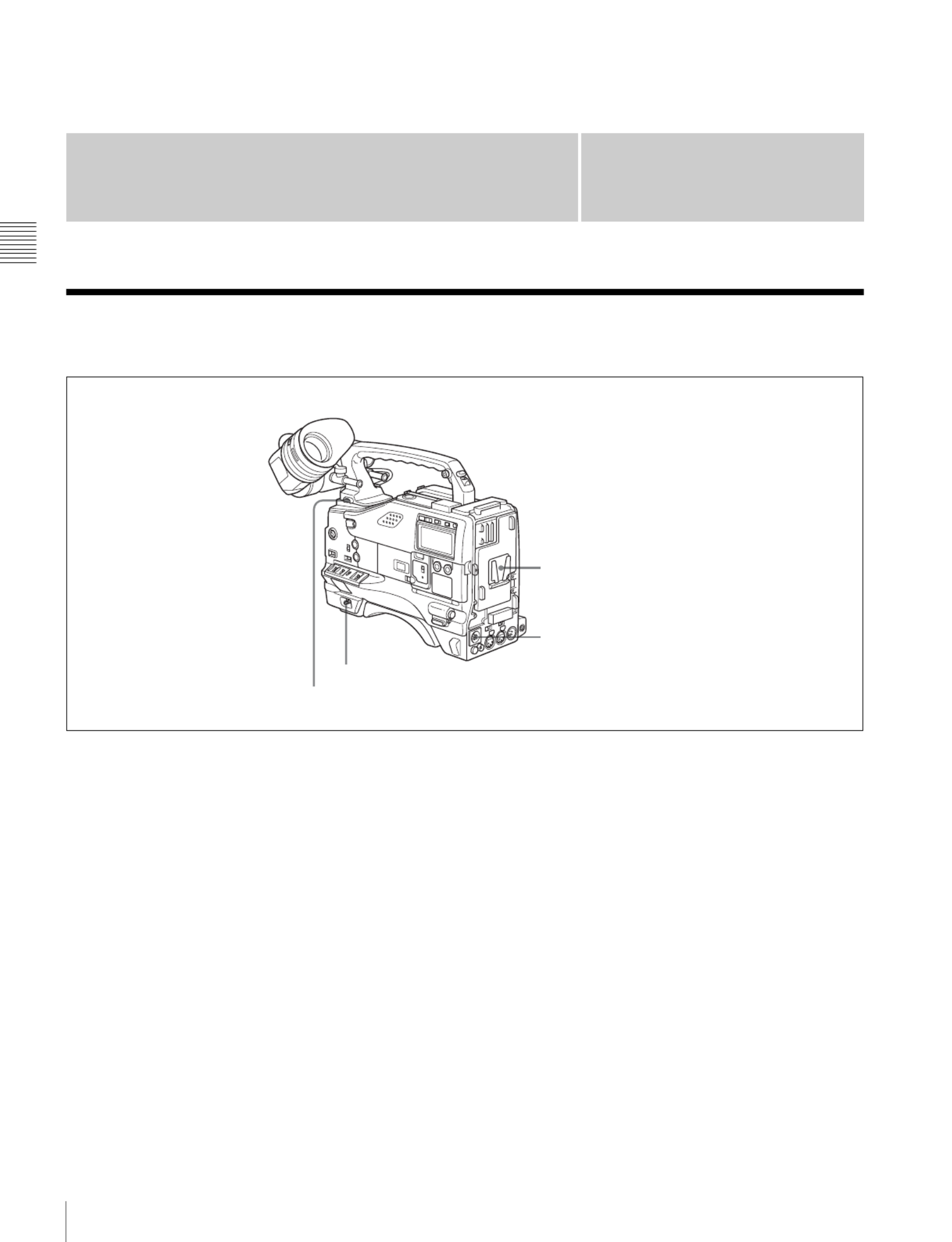
aBattery attachment
Attach a battery pack, BP-GL65, BP-GL95, or BP-L60S.
Furthermore, by attaching an AC-DN10 AC Adaptor, you
can operate the camcorder from AC power.
bDC IN connector (XLR type, 4-pin, male)
To operate the camcorder using an AC power supply,
connect an AC-550/550CE AC Adaptor with the DC
output cable supplied with the adaptor.
To use an external battery, connect its DC output cable to
the DC IN connector.
cPOWER switch
This switch turns the main power supply on and off.
dLIGHT switch
This determines how a video light connected to the LIGHT
connector is turned on and off.
AUTO: When the switch on the video light is in the on
position, putting the camcorder in recording mode
turns the video light on automatically. When using the
auto interval recording mode, the video light is
automatically turned on immediately before recording
starts.
MANUAL: You can turn the video light on or off
manually, using its own switch.
cPOWER switch
dLIGHT switch
bDC IN connector
aBattery attachment
17
Accessory Attachments
Chapter 2 Locations and Functions of Parts and Controls
2-2 Accessory Attachments
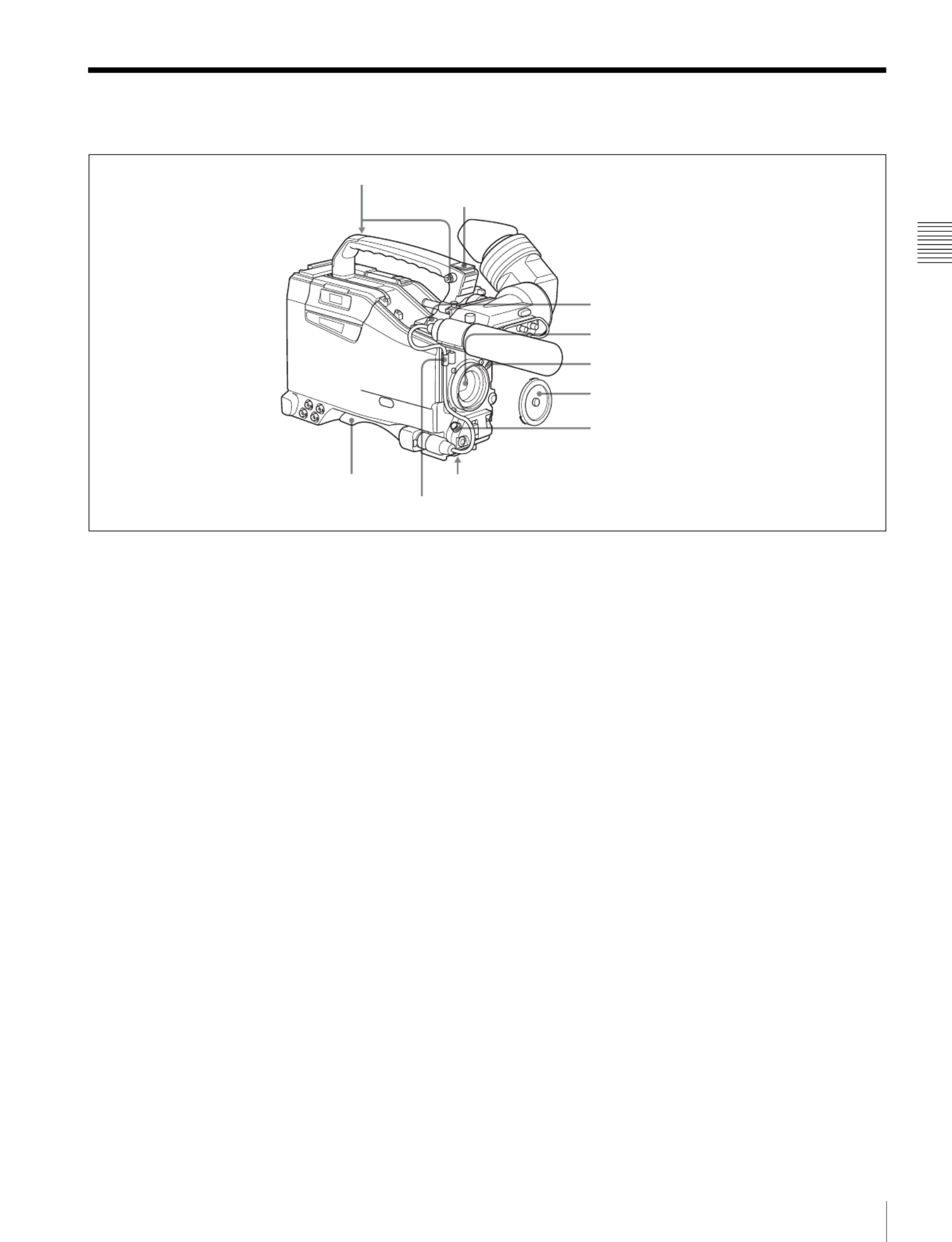
a Shoulder strap posts
Attach the supplied shoulder strap to these posts.
For details, see “7-7 Attaching/Detaching the Shoulder
Strap” on page 120.
b Light shoe
Attach an optional accessory such as a video light to this
shoe.
c LIGHT connector (2-pin, female)
Connect the cable of an Anton Bauer Ultralight System
attached to the light shoe. The system operates with lights
powered by 12 V, with a maximum power consumption of
50 W.
d Lens mount (special bayonet mount)
Use this for mounting the lens.
e Lens locking lever
After inserting the lens in the lens mount, rotate the lens
mount ring with this lever to lock the lens in position.
f Lens mount cap
Remove this cap by pushing up the lens locking lever.
When no lens is mounted, keep this cap fitted for
protection from dust.
g LENS connector (12-pin)
Fit the lens cable to this connector. Contact your Sony
representative for more information about the lens you can
use.
h Tripod mount
When using the camcorder on a tripod, attach the tripod
adaptor (optional).
i Shoulder pad
You can move the shoulder pad forwards or backwards by
raising up the shoulder pad locking lever. Do this to ensure
the best balance when shooting with the camcorder on
your shoulder.
For details, see “7-8 Adjusting the Shoulder Pad Position”
on page 121.
cLIGHT connector
dLens mount
bLight shoe
aShoulder strap posts
eLens locking lever
fLens mount cap
gLENS connector
hTripod mountiShoulder pad
Lens cable clamp

18 Audio Functions
Chapter 2 Locations and Functions of Parts and Controls
2-3 Audio Functions
Audio functions (1)
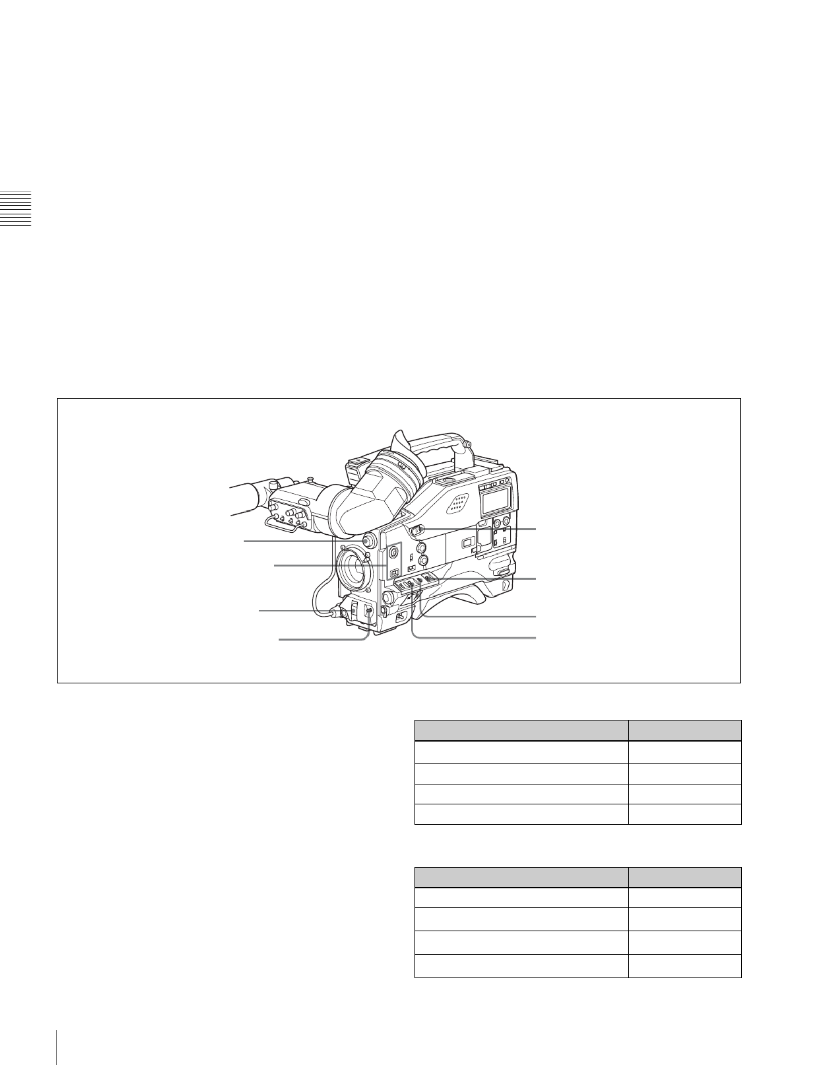
aMicrophone
This is a super-cardioid directional monaural microphone
with an external power supply (+48 V) system.
bMIC IN (microphone input) connector (XLR type,
3-pin, female)
Connect the supplied microphone to this connector. A
microphone other than the supplied one may also be
connected as long as it can operate with the power (+48 V)
supplied from this connector.
By fitting a 5-pin connector (service part number: A-1053-
453-A), you can also use a stereo microphone.
cMIC (microphone) LEVEL control
This control adjusts the audio level of the microphone
connected to the MIC IN connector.
dEARPHONE jacks (minijacks)
You can monitor the E-E sound 1) during recording and
playback sound during playback. Plugging an earphone
into the jack automatically cuts off the built-in speaker.
When an alarm is indicated, you can hear the alarm sound
through the earphone.
1) E-E: Abbreviation of “Electric-to-Electric.” In E-E mode, video and audio
signals input to the camcorder are output after passing through internal
electric circuits only. This can be used to check input signals.
eMONITOR switch and CH-1/2 / CH-3/4 switch
These switches together determine the channel selection
for audio monitor output.
MONITOR switch and CH-1/2 / CH-3/4 switch
CH-1/2 / CH-3/4 switch:
This determines the pair of audio channels selected with
the MONITOR switch.
CH-1/2 position: channels 1 and 2
CH-3/4 position: channels 3 and 4
The signals output from the AUDIO OUT connector and
EARPHONE jacks and the audio level meter in the display
window also depend on the setting of this switch.
MONITOR switch:
This selects the audio monitor channels output to the
earphone or speaker, depending on the setting of the CH-
1/2 / CH-3/4 switch.
cMIC LEVEL control
gALARM volume control
bMIC IN connector
aMicrophone
fMONITOR volume control
eMONITOR switch and CH-1/2 / CH-3/4 switch
hBuilt-in speaker
dEARPHONE jack (front)
dEARPHONE jack (rear)
MONITOR switch
CH-1/2 / CH-3/4 switch

19
Audio Functions
Chapter 2 Locations and Functions of Parts and Controls
fMONITOR volume control
This control adjusts the speaker or earphone volume for
sounds other than the alarm sound. At the minimum
position, no sound can be heard.
gALARM volume control
This control adjusts the speaker or earphone alarm volume.
At the minimum position, no sound can be heard.
ALARM volume control
hBuilt-in speaker
The speaker can be used to monitor E-E sound during
recording, and playback sound during playback. The
speaker also sounds alarms to reinforce visual warnings.
If you connect an earphone to the EARPHONE jack, the
speaker is automatically muted.
See “8-3 Operation Warnings” on page 129 for
information about alarms.
Audio functions (2)
iLEVEL (CH-1/CH-2) (audio channel-1 and
channel-2 recording level) controls
These controls adjust the audio levels of channels 1 and 2
when the AUDIO SELECT switches are set to MANUAL.
jAUDIO SELECT CH-1/CH-2 (audio channel-1 and
channel-2 adjustment method selection) switches
These switches select the audio level adjustment method
for each of audio channels 1 and 2.
AUTO: Select this setting for automatic adjustment.
MANUAL: Select this setting for manual adjustment.
CH-1/2/CH-3/4
switch
position
MONITOR
switch
position
Audio output
CH-1/2 CH-1 Audio channel 1
MIX Mix sound of channels 1 and 2
CH-2 Audio channel 2
CH-3/4 CH-3 Audio channel 3
MIX Mix sound of channels 3 and 4
CH-4 Audio channel 4
Minimum Maximum
CUE IN
CH-1
MIX
CH-2
iLEVEL (CH-1/CH-2) controls
kAUDIO IN CH-1/CH-2/CH-3/CH-4 switches
jAUDIO SELECT CH-1/CH-2 switches
mAUDIO OUT connector
oDC OUT 12V connector
nAUDIO IN CH1/CH2 connectors
and LINE/MIC/+48V ON switches
lCUE IN switch

20 Audio Functions
Chapter 2 Locations and Functions of Parts and Controls
kAUDIO IN CH-1/CH-2/CH-3/CH-4 (audio input
selection) switches
CH-1/CH-2 switches
These switches select the audio input signals to be
recorded on audio channels 1 and 2.
FRONT: The input signal source is the microphone
connected to the MIC IN connector.
REAR: The input signal source is the audio equipment
connected to the AUDIO IN CH1/CH2 connectors.
WIRELESS: The input signal source is a WRR-855A/
855B UHF Synthesized Tuner Unit (option).
CH-3/CH-4 switches
These switches select the audio input signals to be
recorded on audio channels 3 and 4.
F (front): The input signal source is the microphone
connected to the MIC IN connector.
R (rear): The input signal source is the audio equipment
connected to the AUDIO IN CH1/CH2 connectors.
W (wireless): The input signal source is a WRR-855A/
855B UHF Synthesized Tuner Unit (not supplied).
lCUE IN (cue track input) switch
This switch selects the input signal to be recorded on the
cue track.
CH-1: Signal selected by the AUDIO IN CH-1 switch
MIX: Mixed signals selected by the AUDIO IN CH-1 and
CH-2 switches
CH-2: Signal selected by the AUDIO IN CH-2 switch
mAUDIO OUT (audio output) connector (XLR type,
5-pin, male)
This connector outputs the audio signals recorded on audio
channels 1 and 2 or audio channels 3 and 4.
The MONITOR CH-1/2 / CH-3/4 switches allow you to
select the audio signal to be monitored.
nAUDIO IN CH1/CH2 (audio channel-1 and
channel-2 input) connectors (XLR type, 3-pin, female)
and LINE/MIC/+48 V ON (line input/microphone
input/external power supply +48V ON) switches
These are audio input connectors for channels 1 and 2 to
which you can connect audio equipment or a microphone.
The LINE/MIC/+48V ON switches select the audio source
of the audio input signals connected to each of these
connectors.
LINE: Line input audio equipment
MIC: Microphone with an internal power supply
+48V ON: Microphone with an external power supply
system
oDC OUT 12 V (DC power output) connector (4-pin,
female)
This connector supplies power for a WRR-860A/862A/
862B UHF Portable Tuner (option). Do not connect any
equipment other than the UHF portable tuner.

21
Shooting and Recording/Playback Functions
Chapter 2 Locations and Functions of Parts and Controls
2-4 Shooting and Recording/Playback Functions
Shooting and recording/playback functions (1)
aTALLY indicator
Setting the TALLY switch to HIGH or LOW enables this
indicator. The indicator lights during recording on the
VTR. Like the REC indicator in the viewfinder, it flashes
to indicate a problem. You can set the indicator brightness
with the TALLY switch.
bBRIGHT (brightness) control
This control adjusts the picture brightness on the
viewfinder screen. It has no effect on the camera output
signal.
cCONTRAST control
This control adjusts the picture contrast on the viewfinder
screen. It has no effect on the camera output signal.
dPEAKING control
This control adjusts the sharpness of the picture on the
viewfinder screen to make focusing easier. It has no effect
on the camera output signal.
eZEBRA switch
This switch controls the zebra pattern1) on the viewfinder
screen.
ON: The zebra pattern is displayed and stays.
OFF: No zebra pattern is displayed.
MOMENT: The zebra pattern is displayed and stays for 5
to 6 seconds.
The zebra pattern is factory set to indicate picture areas
where the video level is approximately 70%.You can use
the setup menu to change the setting so that areas where
the video level is 100% and above are also displayed at the
same time.
1) The zebra pattern aids in manual iris adjustment by indicating areas of the
picture where the video level is approximately 70% and 100% and above.
For information about how to change the zebra pattern
setting in the setup menu, see “5-2-5 Setting the
Viewfinder” on page 81.
fTALLY switch
This switch controls the TALLY indicator, setting its
brightness (HIGH or LOW) or turning it off.
HIGH: The TALLY indicator brightness is high.
OFF: The TALLY indicator is disabled.
LOW: The TALLY indicator brightness is low.
gViewfinder
hDiopter adjustment ring
aTALLY indicator Eyecup
bBRIGHT control
cCONTRAST control
dPEAKING control
eZEBRA switch
fTALLY switch
iViewfinder front-rear
positioning lever
jViewfinder left-right positioning ring
kCamera operator tally indicator
lViewfinder stopper
mLOCK knob
22 Shooting and Recording/Playback Functions
Chapter 2 Locations and Functions of Parts and Controls
gViewfinder
The viewfinder lets you view the image in black and white
while shooting, recording or playing back. It also displays
various warnings and messages related to the settings or
operating conditions of the camcorder, a zebra pattern,
safety zone marker 1), and center marker 2).
1) The safety zone marker is a rectangle indicating the effective picture area.
2) The center marker indicates the center of the picture with a crosshair.
For details, see “5-2-4 Setting the Marker Display” on
page 81.
hDiopter adjustment ring
Use this ring to adjust the viewfinder image for your
vision.
iViewfinder front-rear positioning lever
To adjust the viewfinder position in the front-rear
direction, loosen this lever and the LOCK knob. After
adjustment, retighten this lever and the LOCK knob.
jViewfinder left-right positioning ring
Loosen this ring to move the viewfinder sideways.
kCamera operator tally indicator
This indicator lights while the camcorder is recording.
Slide the window open when you shoot with your eye away
from the viewfinder. This indicator flashes when the
battery level is running low or the disc is almost full.
lViewfinder stopper
Pull up this stopper to detach the viewfinder from the
camera.
mLOCK knob
To adjust the viewfinder position in the front-rear
direction, loosen this knob and the viewfinder front-rear
positioning lever. After adjustment, retighten this knob and
the viewfinder front-rear positioning lever.
Shooting and recording/playback functions (2)
nFILTER selector
Use this selector to select the most appropriate filter to
match the light source illuminating the subject.
When this selector is used with the display mode set to 3,
the new setting appears on the viewfinder screen for about
3 seconds. (e.g.: ND: 1, CC: B)
The relationships between the selector settings and filter
selections as well as examples of filters for different
shooting conditions are as follows:
1) A type of special effect filter, which generates a cross of light on a
highlighted portion.
nFILTER selector
oASSIGN 1/2 switches
pSHUTTER selector
qAUTO W/B BAL switch
tWHITE BAL switch
sOUTPUT/DCC selector
rGAIN selector
uTURBO GAIN button
FILTER selector (outer knob) setting CC filter selection
ACross filter 1)
B 3200K
C 4300K
D 6300K
FILTER selector (inner knob) setting ND filter selection
1 Clear
21/4 ND
31/16 ND
41/64 ND

23
Shooting and Recording/Playback Functions
Chapter 2 Locations and Functions of Parts and Controls
oASSIGN 1/2 switches
You can assign the desired functions to each of the
ASSIGN 1 switch (push button) and ASSIGN 2 switch
(sliding) on the FUNCTION 1 page of the USER menu.
For details, see “5-3-5 Assigning Functions to Assignable
Switches” on page 90.
pSHUTTER selector
Set this selector to ON to use the electronic shutter. Push it
down to SELECT to switch the shutter speed or mode
setting within the range previously set with the setup
menu.
When this selector is operated, the new setting appears on
the setting change/adjustment progress message display
area for about 3 seconds.
For details about the shutter speed and mode settings, see
“4-2 Setting the Electronic Shutter” on page 58.
qAUTO W/B BAL (automatic white/black balance
adjustment) switch
This switch activates the white balance and black balance
automatic adjustment functions.
WHT: Automatic adjustment of the white balance. If the
WHITE BAL switch is set to A or B, the white balance
setting is stored in the corresponding memory. The
memory stores a separate white balance setting for each
filter setting.
BLK: Automatic adjustment of the black set and black
balance.
rGAIN selector
This selector switches the gain of the video amplifier to
match the lighting conditions during shooting. The gains
corresponding to the L, M, and H settings can be selected
from the setup menu. The factory settings are L = 0 dB, M
= 9 dB, and H = 18 dB.
When this selector is adjusted, the new setting appears on
the setting change/adjustment progress message display
area of the viewfinder screen for about 3 seconds.
For details about setting the gain values, see “5-3-1
Setting Gain Values for the GAIN Selector Positions” on
page 87.
sOUTPUT/DCC (output signal/dynamic contrast
control) selector
This selector switches the video signal that is output to the
VTR, viewfinder, and video monitor, between the
following two.
BARS: Outputs the color bar signal.
CAM: Outputs the video signal from the camera. When
this is selected, you can switch DCC1) on and off with
this selector.
1) DCC (Dynamic Contrast Control)
Against a very bright background with the iris opening adjusted to the
subject, objects in the background will be lost in the glare. The DCC
function will suppress the high intensity and restore much of the lost detail
and is particularly effective in the following cases.
•Shooting people in the shade on a sunny day
•Shooting a subject indoors, against a background through a window
•Any high contrast scene
OUTPUT/DCC selector
tWHITE BAL (white balance memory) switch
This switch controls the white balance setting.
PRST (preset): Adjusts the color temperature
corresponding to the position of the FILTER selector.
Use the PRST setting when you have no time to adjust
the white balance.
A or B: When the AUTO W/B BAL switch is pushed to
WHT, the white balance is automatically adjusted
according to the current position of the FILTER
selector, and the adjusted value is stored in either
memory A or memory B. (There are two memories for
each filter, allowing a total of eight adjustments to be
stored.) When this switch is set to A or B, the
camcorder automatically adjusts itself to the stored
value corresponding to the current settings of this
switch and the FILTER selector.
You can use the AUTO W/B BAL switch even when
AT W 1) is in use.
1) ATW (Auto Tracing White Balance)
The white balance of the picture being shot is adjusted automatically for
varying lighting conditions.
Shooting condition CC filter ND filter
Sunrise and sunset; inside
studio
B (3200K) 1 (clear)
Clear skies C (4300K) or
D (6300K) 2 (1/4 ND) or
3 (1/16 ND)
Cloudy or raining D (6300K) 1 (clear) or
2 (1/4 ND)
Very bright conditions such
as snow, at high altitudes,
or at the seashore
C (4300K) or
D (6300K) 3 (1/16 ND) or
4 (1/64 ND)
BARS, DCC OFF
A color bar signal is output and the
DCC circuit does not operate. For
example, use the setting for the
following purposes.
• Adjusting the video monitor
• Recording the color bar signal
CAM, DCC OFF
The video signal from the camera is
output, and the DCC circuit does not
operate.
CAM, DCC ON
The video signal from the camera is
output, and the DCC circuit operates.

25
Shooting and Recording/Playback Functions
Chapter 2 Locations and Functions of Parts and Controls
Shooting and recording/playback functions (4)
yVTR START button
Press this button to start recording. Press it again to stop
recording. The effect is exactly the same as that of the VTR
button on the lens.
When the REC SWITCH function is assigned to the
ASSIGN 1 switch (push button), you can use the switch as
the REC START button.
zVTR SAVE/STBY (standby) switch
This switch controls the VTR power mode during pauses
in recording.
SAVE: Power saving mode. When you press the VTR
START button, there is a short delay before recording
starts, but power consumption in this mode is less than
in standby mode, so that battery life is extended. When
the switch is set to SAVE, the SAVE indicator in the
viewfinder lights.
STBY: Standby mode. Recording starts as soon as you
press the REC START button.
• Avoid allowing the camcorder to remain in STBY
(standby) mode for a long time.
• Even if the switch is set to the STBY position, the
camcorder can automatically turn to power saving mode
if the tape does not run for a certain period. In such a
case, the VTR SAVE indicator in the viewfinder lights.
This function is effective when a setting other than OFF
is selected for the STBY OFF TIMER item on the VTR
MODE page of the MAINTENANCE menu. The STBY
OFF TIMER item also allows you to select the length of
time until the camcorder turns to power saving mode.
For detailed information, see “3-5 Setting the Stand-by off
Timer During Rec-Pause” on page 54.
wj EJECT button
Press this button to eject or load a cassette.
wk REW (rewind) button and indicator
Press this button to rewind the tape. The indicator lights
during rewinding.
wl F FWD (fast forward) button and indicator
Press this button to fast forward the tape. The indicator
lights during fast forward.
e; PLAY button and indicator
Press this button to view the recorded picture in the
viewfinder or on the color video monitor. The indicator
lights during playback.
The 4 times normal speed search function is provided to
make it far quicker to find a desired location of the tape.
Press the REW button or F FWD button during playback
to view the 4 times normal speed search picture.
ea STOP button
Press this button to stop the tape.
yVTR START button
zVTR SAVE/STBY connector
wj EJECT button
wk REW button and indicator
wl F FWD button and indicator
e; PLAY button and indicator
ea STOP button
Notes

26 Menu Operating Section
Chapter 2 Locations and Functions of Parts and Controls
2-5 Menu Operating Section
Menu operation section
a “Memory Stick” compartment
Open the cover of the “Memory Stick” compartment by
pressing the MEMORY STICK OPEN button and insert
the “Memory Stick.”
To remove, press the eject button.
During data writing/loading to/from the “Memory Stick,”
the ACCESS indicator lights or flashes.
For details, see “6-1-1 Handling the “Memory Stick”” on
page 100.
b MENU knob
Use this knob to change the page selection or a setting
within the menu.
Press: If you press this knob when the arrow ( b) is placed
at the page title on the menu, the arrow changes to a
question mark (?) and you can change the page by
turning this knob.
When the arrow mark is placed at a position other than
the page title, you can change the setting of the current
item by pressing and turning this knob.
Turn: Turn this knob to change the page or change item
settings.
c STATUS ON/SEL / OFF (menu display on/page
selection/display off) switch
To enable this switch, set the MENU ON/OFF switch to
OFF.
Closing the cover automatically sets the MENU ON/OFF
switch to OFF.
ON/SEL: Each time this switch is pushed upward, a
window to confirm the menu settings and status of the
camcorder appears on the viewfinder screen. The
window consists of three pages, which are switched
each time the switch is pushed upward. Each page is
displayed for about 10 seconds.
OFF: To clear the page immediately after display, push
this switch down to the OFF position.
You can select the pages to be displayed on the menu.
For details, see “5-2-8 Displaying the Status Confirmation
Windows” on page 84.
d MENU ON/OFF switch
To use this switch, open the cover.
e CANCEL/PRST / ESCAPE switch
b MENU knob
c STATUS ON/SEL / OFF switch
d MENU ON/OFF switch
a “Memory Stick” compartment
Cover
ACCESS indicator
MEMORY STICK OPEN button
Eject button
“Memory Stick”
f

27
Menu Operating Section
Chapter 2 Locations and Functions of Parts and Controls
This switch is used to display the menu on the viewfinder
screen or the test signal screen.
Closing the cover automatically sets this switch to OFF.
ON: Displays the menu on the viewfinder screen or the test
signal screen, at the last accessed page. When the menu
is used for the first time, the first page is displayed.
OFF: Removes the menu from the viewfinder screen or the
test signal screen.
eCANCEL/PRST (preset) / ESCAPE switch
To enable this switch, set the MENU ON/OFF switch to
ON.
Closing the cover automatically sets the MENU ON/OFF
switch to OFF.
CANCEL/PRST: Pushing this switch up to this position
displays the message to confirm whether the previous
settings are cancelled or settings are reset to their initial
values, depending on the menu operating condition.
Pushing this switch up to this position again cancels the
previous settings or resets the settings to their initial
values.
ESCAPE: Use this switch when the menu page, which has
a hierarchical structure, is opened. Each time the switch
is pushed to this position, the page returns to one stage
higher in the hierarchy.

30 Warnings and Indications
Chapter 2 Locations and Functions of Parts and Controls
2-7 Warnings and Indications
Besides the viewfinder, speaker and earphones, the
indicators and displays described in this section also
provide you with information such as the operating state of
the camcorder and warnings.
Warning and indication functions
aTALLY indicator
Setting the TALLY switch on the viewfinder to HIGH or
LOW enables this indicator. It lights when the VTR starts
recording. Like the REC indicator in the viewfinder, it also
flashes to provide warnings. The brightness of this
indicator when it is lit can be switched with the TALLY
switch.
bDISPLAY switch
This switches the indications on the viewfinder screen on
or off.
ON: The indications appear on the viewfinder screen.
OFF: The indications do not appear on the viewfinder
screen.
Setting the MENU ON/OFF switch to ON displays the
menu on the viewfinder screen even if the DISPLAY
switch is set to OFF.
cTALLY switch
This switch controls the TALLY indicator as follows:
HIGH: The TALLY indicator brightness is high.
OFF: The TALLY indicator is disabled.
LOW: The TALLY indicator brightness is low.
dBACK TALLY indicator
When the BACK TALLY switch is set to ON, this indicator
has the same function as the TALLY indicator.
eBACK TALLY switch
This switch enables or disables the BACK TALLY and
REAR TALLY indicators.
ON: The BACK TALLY and REAR TALLY indicators are
enabled.
OFF: The BACK TALLY and REAR TALLY indicators
are disabled.
fLIGHT switch
This switch turns on/off the display panel light.
aTALLY indicator
bDISPLAY switch
cTALLY switch
dBACK TALLY indicator
eBACK TALLY switch
iREAR TALLY indicator
hDisplay panel
gWARNING indicator
fLIGHT switch
Note

33
Indicators in the Viewfinder
Chapter 2 Locations and Functions of Parts and Controls
2-9 Indicators in the
Viewfinder
Several indicators are provided above and below the
viewfinder screen to indicate the current state and
adjustments of the camera.
Indicators on the viewfinder
aTALLY (green tally) indicator
This indicator lights when the camcorder is in Picture
Cache mode. Also, this indicator lights when a green tally
signal is received from the camera control unit.
It flashes in Interval Rec mode.
bREC (recording, red tally) indicator
This indicator lights red when recording starts and remains
lit during recording. It also lights when a red tally signal is
received from the camera control unit and flashes to give a
warning.
For details, see “8-3 Operation Warnings” on page 129.
cBATT (battery) indicator
This indicator starts flashing when the battery connected to
the camcorder is nearly exhausted, and stays lit when the
battery is completely exhausted.
The battery power level at which the indicator starts
flashing can be set on the BATTERY page of the
MAINTENANCE menu.
For details, refer to the Maintenance Manual.
d (warning) indicator
This indicator lights when any of the following conditions
occurs with the corresponding item set to ON on the “!”
LED page of the USER menu.
• The gain is set to other than 0 dB.
• The SHUTTER selector is set to ON.
• The WHITE BAL switch is set to PRST.
• ATW is enabled.
• The lens extender is used.
• The FILTER selector is set to other than ND:1/CC:B.
• The reference value of auto iris override is not the
standard value.
eSpare indicator
This is a spare indicator. Setting the REC TALLY item to
“BOTH” on the FUNCTION 3 page of the
MAINTENANCE menu makes it possible to use this as a
REC indicator.
fSAVE indicator
This indicator lights when the VTR SAVE/STBY switch is
set to SAVE, putting the VTR into power save mode.
aTALLY indicator
bREC indicator
cBATT indicator
d indicator
eSpare indicator
fSAVE indicator
Viewfinder screen
39
Recording
Chapter 3 Recording and Playback
4
When the CONTENTS page is displayed, turn the
MENU knob to move the b mark to ESSENCE
MARK then push the MENU knob.
When any page of the MAINTENANCE menu is
displayed, turn the MENU knob until the ESSENCE
MARK or ESSENCE MARK2 page appears, then
push the MENU knob.
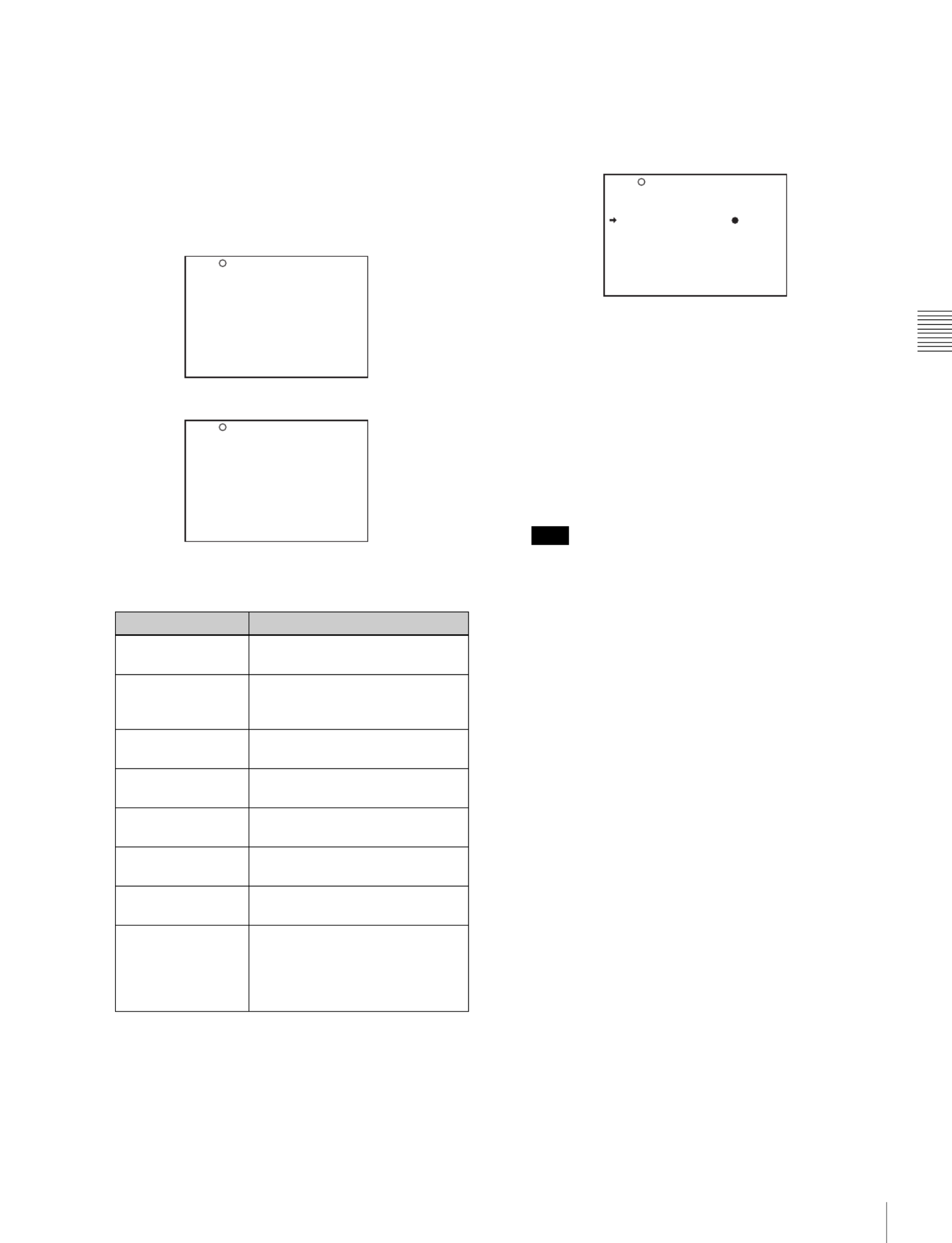
ESSENCE MARK page
ESSENCE MARK2 page
The following items on these pages are for setting the
corresponding essence marks:
You can check whether any of the essence marks that
are automatically recorded (OVER AUDIO LIMIT,
GAIN CHG MARK, FILTER CHG MARK,
SHUTTER CHG MARK, WHITE CHG MARK,
FLASH MARK) has been recorded, by setting the
display for recorded essence marks ON.
For details on the display setting, see “5-2 Status
Display on the Viewfinder Screen” (page 77).
5
Turn the MENU knob to move the b mark to the item
to be set.
6
Push the MENU knob.
The b mark to the left of the item changes to the z
mark, and the z mark to the left of the setting changes
to the ? mark.
7
Turn the MENU knob clockwise or counter clockwise
until the desired setting appears.
To record the mark on tape, select ON.
To not record the mark, select OFF.
Whether or not to record good shot marks (shot mark
1 and shot mark 2) and recording start mark in the
system area is determined by the ON/OFF settings of
the corresponding items regardless of the LTC UB-
MARKER setting on the ESSENCE MARK page.
8
Push the MENU knob.
9
Perform settings for the remaining marks, repeating
steps 5 to 8.
10
When you set FLASH MARK to ON, select the
threshold value (1 to 20) of the luminance level change
for recording the mark.
11
Set the MENU ON/OFF switch to OFF to end the
menu operation.
Settings for recording good shot marks
and recording start mark to the LTC-UBIT
area
Good shot marks (shot mark 1 and shot mark 2) and
recording start mark can also be recorded to the LTC-UBIT
area of tape.
Follow the procedures below:
Mark Condition
REC START MARK To be recorded when recording
starts.
SHOT MARK 1/2 To be recorded when the RET
button on the lens is manually
operated.
OVER AUDIO
LIMIT
To be recorded when the audio
level exceeds 0 dBFS.
GAIN CHG MARK To be recorded when the gain
value changes.
FILTER CHG
MARK
To be recorded when the filter is
changed.
SHUTTER CHG
MARK
To be recorded when the shutter
speed changes.
WHITE CHG
MARK
To be recorded when the white
balance changes.
FLASH MARK To be recorded when the
luminance suddenly changes,
such as when the flash is
exposed or the unit is moved
indoors from outdoors.
LTC UB-MARKER : SET
REC START MARK : OFF
SHOTMARK 1 : OFF
SHOTMARK 2 : OFF
SHOT TIME DISP : MD:HM
?M 1 0 ES SEN C E M A RK
OVER AUDIO LIMIT: ON
GAIN CHG MARK : ON
FILTER CHG MARK : ON
SHUTTER CHG MARK: ON
WHITE CHG MARK : ON
FLASH MARK : ON
FLASH MARK LEVEL: 10
E.MARK SD LINE : 17
?M 1 1 ES SEN C E M A RK2
Note
LTC UB-MARKER : SET
REC START MARK : OFF
SHOTMARK 1 : OFF
SHOTMARK 2 : OFF
SHOT TIME DISP : MD:HM
M 1 0 ES SEN C E M ARK
Product specificaties
| Merk: | Sony |
| Categorie: | Camcorder |
| Model: | DVW-970P |
Heb je hulp nodig?
Als je hulp nodig hebt met Sony DVW-970P stel dan hieronder een vraag en andere gebruikers zullen je antwoorden
Handleiding Camcorder Sony

28 December 2024
3 September 2024
7 April 2024
6 Januari 2024
30 September 2023
25 September 2023
14 Augustus 2023
1 Augustus 2023
2 Juli 2023
20 Juni 2023
Handleiding Camcorder
- Camcorder Braun
- Camcorder HP
- Camcorder Samsung
- Camcorder Xiaomi
- Camcorder Panasonic
- Camcorder Nikon
- Camcorder Canon
- Camcorder Garmin
- Camcorder JVC
- Camcorder Kenwood
- Camcorder Medion
- Camcorder Olympus
- Camcorder Quintezz
- Camcorder Toshiba
- Camcorder VTech
- Camcorder Abus
- Camcorder Activeon
- Camcorder AEE
- Camcorder Agfa
- Camcorder Agfaphoto
- Camcorder Aiptek
- Camcorder Airis
- Camcorder ATN
- Camcorder Bauer
- Camcorder BenQ
- Camcorder BlackVue
- Camcorder Braun Phototechnik
- Camcorder Bresser
- Camcorder Denver
- Camcorder DJI
- Camcorder Dnt
- Camcorder DOD
- Camcorder Drift
- Camcorder Easypix
- Camcorder EE
- Camcorder Elmo
- Camcorder Ematic
- Camcorder Energy Sistem
- Camcorder Envivo
- Camcorder FHD 1080P
- Camcorder Flir
- Camcorder Fujifilm
- Camcorder Gembird
- Camcorder Genius
- Camcorder Goclever
- Camcorder GoPro
- Camcorder Hama
- Camcorder Hitachi
- Camcorder Hyundai
- Camcorder Iget
- Camcorder Insignia
- Camcorder Insta360
- Camcorder Intenso
- Camcorder Ion
- Camcorder ISAW
- Camcorder Kitvision
- Camcorder Kodak
- Camcorder Kogan
- Camcorder Konica Minolta
- Camcorder Konig
- Camcorder Kyocera
- Camcorder Lamax
- Camcorder Leica
- Camcorder Lenco
- Camcorder Leotec
- Camcorder Lexibook
- Camcorder Linksys
- Camcorder Logitech
- Camcorder Magellan
- Camcorder Maginon
- Camcorder Mamiya
- Camcorder Marshall
- Camcorder Midland
- Camcorder Minolta
- Camcorder Minox
- Camcorder Mio
- Camcorder MMTC
- Camcorder Mobius
- Camcorder Mpman
- Camcorder National Geographic
- Camcorder Nedis
- Camcorder Nikkei
- Camcorder Polaroid
- Camcorder Praktica
- Camcorder Prestigio
- Camcorder Pyle
- Camcorder RCA
- Camcorder Renkforce
- Camcorder Replay
- Camcorder Ricoh
- Camcorder Rollei
- Camcorder Sakar
- Camcorder Salora
- Camcorder Samson
- Camcorder Sanyo
- Camcorder SeaLife
- Camcorder Sencor
- Camcorder Sharp
- Camcorder Silvercrest
- Camcorder SJCAM
- Camcorder Soundmaster
- Camcorder Spypoint
- Camcorder Storex
- Camcorder TacTic
- Camcorder TomTom
- Camcorder Transcend
- Camcorder Traveler
- Camcorder Trust
- Camcorder Uniden
- Camcorder Veho
- Camcorder Viewsonic
- Camcorder Vivitar
- Camcorder Zagg
- Camcorder Zoom
- Camcorder Jay-tech
- Camcorder Jobo
- Camcorder OK
- Camcorder Oregon Scientific
- Camcorder Overmax
- Camcorder Macally
- Camcorder Naxa
- Camcorder T'nB
- Camcorder Cobra
- Camcorder Tracer
- Camcorder Hamlet
- Camcorder Akaso
- Camcorder Trevi
- Camcorder Contax
- Camcorder Hamilton Buhl
- Camcorder Swann
- Camcorder Nilox
- Camcorder Cisco
- Camcorder ARRI
- Camcorder Beaulieu
- Camcorder Bolex
- Camcorder CamOne
- Camcorder Contour
- Camcorder EVOLVEO
- Camcorder RunCam
- Camcorder Whistler
- Camcorder Dragon Touch
- Camcorder Coby
- Camcorder Mediacom
- Camcorder Zorki
- Camcorder Aida
- Camcorder DataVideo
- Camcorder SBS
- Camcorder Blackmagic Design
- Camcorder Contour Design
- Camcorder Kaiser Baas
- Camcorder DXG
- Camcorder Vupoint Solutions
- Camcorder Curve
- Camcorder Kobian
- Camcorder RSC
- Camcorder Stealth Cam
- Camcorder Aqua-Vu
- Camcorder Qoltec
- Camcorder Best Buy
- Camcorder IOPLEE
- Camcorder Microtek
Nieuwste handleidingen voor Camcorder

12 Maart 2025
12 Maart 2025
12 Maart 2025
4 Februari 2025
11 December 2024
6 December 2024

6 December 2024
6 December 2024
6 December 2024

23 November 2024