HP g6-2269sa Handleiding
Lees hieronder de 📖 handleiding in het Nederlandse voor HP g6-2269sa (104 pagina's) in de categorie Laptop. Deze handleiding was nuttig voor 62 personen en werd door 2 gebruikers gemiddeld met 4.5 sterren beoordeeld
Pagina 1/104

HP Pavilion g6 Notebook PC
Maintenance and Service Guide

© Copyright 2012 Hewlett-Packard
Development Company, L.P.
AMD is a trademark of Advanced Micro
Devices, Inc. Bluetooth is a trademark
owned by its proprietor and used by
Hewlett-Packard Company under license.
Microsoft, Windows, and Windows 7 are
U.S. registered trademarks of Microsoft
Corporation. SD Logo is a trademark of its
proprietor.
The information contained herein is subject
to change without notice. The only
warranties for HP products and services are
set forth in the express warranty statements
accompanying such products and services.
Nothing herein should be construed as
constituting an additional warranty. HP shall
not be liable for technical or editorial errors
or omissions contained herein.
First Edition: April 2012
Document Part Number: 685779-001

Safety warning notice
WARNING! To reduce the possibility of heat-related injuries or of overheating the device, do not
place the device directly on your lap or obstruct the device air vents. Use the device only on a hard,
flat surface. Do not allow another hard surface, such as an adjoining optional printer, or a soft
surface, such as pillows or rugs or clothing, to block airflow. Also, do not allow the AC adapter to
contact the skin or a soft surface, such as pillows or rugs or clothing, during operation. The device
and the AC adapter comply with the user-accessible surface temperature limits defined by the
International Standard for Safety of Information Technology Equipment (IEC 60950).
iii

iv Safety warning notice

Table of contents
1 Product description ........................................................................................................................................ 1
2 External component identification ................................................................................................................ 5
Display .................................................................................................................................................. 5
Top ....................................................................................................................................................... 6
Buttons and speakers .......................................................................................................... 6
Keys ..................................................................................................................................... 7
Lights ................................................................................................................................... 8
TouchPad ............................................................................................................................ 9
Left side .............................................................................................................................................. 10
Right side ........................................................................................................................................... 11
Bottom components ........................................................................................................................... 12
3 Illustrated parts catalog ............................................................................................................................... 13
Serial number location ........................................................................................................................ 13
Computer major components ............................................................................................................. 14
Display assembly subcomponents ..................................................................................................... 18
Mass storage devices ......................................................................................................................... 19
Miscellaneous parts ............................................................................................................................ 20
Sequential part number listing ............................................................................................................ 21
4 Removal and replacement procedures ....................................................................................................... 25
Preliminary replacement requirements ............................................................................................... 25
Tools required .................................................................................................................... 25
Service considerations ....................................................................................................... 25
Plastic parts ....................................................................................................... 25
Cables and connectors ..................................................................................... 25
Drive handling ................................................................................................... 26
Grounding guidelines ......................................................................................................... 26
Electrostatic discharge damage ........................................................................ 26
Packaging and transporting guidelines ............................................. 28
Component replacement procedures ................................................................................................. 29
Service label ...................................................................................................................... 30
Computer feet .................................................................................................................... 30
Battery ............................................................................................................................... 32
Service door ....................................................................................................................... 33
v

Optical drive ....................................................................................................................... 34
Hard drive .......................................................................................................................... 36
Memory module ................................................................................................................. 38
WLAN module .................................................................................................................... 41
Keyboard ........................................................................................................................... 43
Top cover ........................................................................................................................... 47
Speakers ............................................................................................................................ 50
Power button board ........................................................................................................... 51
TouchPad button board ..................................................................................................... 53
TouchPad LED board ........................................................................................................ 54
Display assembly ............................................................................................................... 56
USB board ......................................................................................................................... 62
Power connector ................................................................................................................ 63
System board ..................................................................................................................... 64
RTC battery ....................................................................................................................... 67
Fan and heat sink .............................................................................................................. 68
PCH heat sink .................................................................................................................... 71
Processor ........................................................................................................................... 72
Optical drive cable ............................................................................................................. 73
5 Using Setup Utility (BIOS) and System Diagnostics ................................................................................. 75
Starting Setup Utility (BIOS) ............................................................................................................... 75
Updating the BIOS ............................................................................................................................. 75
Determining the BIOS version ........................................................................................... 75
Downloading a BIOS update ............................................................................................. 76
Using System Diagnostics .................................................................................................................. 76
6 Specifications ................................................................................................................................................ 78
Computer specifications ..................................................................................................................... 78
39.6-cm (15.6-in) display specifications ............................................................................................. 79
Hard drive specifications .................................................................................................................... 80
DVD±RW and CD-RW SuperMulti Double-Layer Combo Drive specifications .................................. 81
Blu-ray Disc ROM and DVD±R/RW SuperMulti Double-Layer Drive specifications ........................... 82
7 Backing up, restoring, and recovering ....................................................................................................... 83
Creating backups ............................................................................................................................... 83
Creating recovery media to recover the original system .................................................... 83
What you need to know ..................................................................................... 83
Creating the recovery media ............................................................ 84
Creating system restore points .......................................................................................... 84
vi

What you need to know ..................................................................................... 84
Creating a system restore point ........................................................................ 84
Backing up system and personal information .................................................................... 84
Tips for a successful backup ............................................................................. 85
What you need to know ..................................................................................... 85
Creating a backup using Windows Backup and Restore .................................. 85
Restore and recovery ......................................................................................................................... 86
Restoring to a previous system restore point .................................................................... 86
Restoring specific files ....................................................................................................... 86
Restoring specific files using Windows Backup and Restore ............................ 86
Recovering the original system using HP Recovery Manager ........................................... 86
What you need to know ..................................................................................... 86
Recovering using HP Recovery partition (select models only) ......................... 87
Recovering using the recovery media ............................................................... 87
Changing the computer boot order ................................................... 87
8 Power cord set requirements ...................................................................................................................... 89
Requirements for all countries ............................................................................................................ 89
Requirements for specific countries and regions ............................................................................... 90
9 Recycling ....................................................................................................................................................... 92
Index ................................................................................................................................................................... 93
vii

viii

1 Product description
Category Description
Product Name HP Pavilion g6 Notebook PC
Processors AMD® A10-4600M processor (3.2 GHz/2.3 GHz, 1600 MHz/4.0 MB L2 cache, DDR3,
quad core, 35W)
AMD A8-4500M processor (2.8 GHz/1.9 GHz, 1600 MHz/4.0 MB L2 cache, DDR3,
quad core, 35W)
AMD A6-4400M processor (3.2 GHz/2.7 GHz, 1600 MHz/1.0 MB L2 cache, DDR3,
dual core, 35W)
Chipset AMD A70M FCH
Graphics Internal Graphics (UMA):
●AMD Radeon HD 7660G graphics supporting HD decode, DX11, and HDMI for
use with computer models equipped with an AMD A10-4600M processor
●AMD Radeon HD 7640G graphics supporting HD decode, DX11, and HDMI for
use with computer models equipped with an AMD A8-4500M processor
●AMD Radeon HD 7520G graphics supporting HD decode, DX11, and HDMI for
use with computer models equipped with an AMD A6-4400M processor
Switchable Discrete Graphics:
●AMD Radeon HD 7670M with 2 GB of dedicated video memory (128 MB x 16
DDR3 @ 900 MHz x 8 pcs) 128-bit M2 package, supports HD Decode, DX11,
HDMI, and PX5
●AMD Radeon HD 7670M with 1 GB of dedicated video memory (64 MB x 16
DDR3 @ 900 MHz x 8 pcs) 128-bit M2 package, supports HD Decode, DX11,
HDMI, and PX5
Dual graphics:
●AMD Radeon HD 7660G+HD 7670M Dual Graphics for computer models
equipped with an AMD A10-4600M APU and AMD Radeon HD 7670M graphics
card
●AMD Radeon HD 7640G+HD 7670M Dual Graphics for computer models
equipped with an AMD A8-4500M APU and AMD Radeon HD 7670M graphics
card
●AMD Radeon HD 7520G+HD 7670M Dual Graphics for computer models
equipped with an AMD A6-4400M APU and AMD Radeon HD 7670M graphics
card (no support for 1 DIMM memory)
Display Panel 39.6 cm (15.6 in) high-definition (HD), light-emitting diode (LED), SVA BrightView
(1366×768) display; typical brightness: 200 cd/m2 (nits)
All display assemblies include two wireless local area network (WLAN) antenna
cables
Supports 16:9 ultra-wide aspect ratio
1

Category Description
Memory 2 customer-accessible/upgradable SODIMM slots:
DDR3-1333 MHz Dual Channel Support
Supports the following configurations up to 8 GB:
●8192 MB total system memory (4096×2) (No support for 32 bit OS)
●6144 MB total system memory (4096×1 + 2048×1) (No support for 32 bit OS)
●4096 MB total system memory (4096×1 or 2048×2)
●2048 MB total system memory (2048×1)
Hard drives Supports 6.35 cm (2.5 in) hard drives in 9.5 mm 7.0 mm (.37 in) and (.28 in)
thicknesses
Supports HP 3D Drive Guard
Customer-accessible
Serial ATA (SATA)
Supports the following single hard drive configurations:
●1 TB, 5400 rpm, 9.5 mm
●750 GB, 7200 rpm, 9.5 mm
●750 GB, 5400 rpm, 9.5 mm
●640 GB, 5400 rpm, 9.5 mm
●500 GB, 7200 rpm, 9.5 mm
●500 GB, 5400 rpm, 9.5 mm
●320 GB, 7200 rpm, 9.5 mm and 7.0 mm
●320 GB, 5400 rpm, 9.5 mm and 7.0 mm
Optical drive Fixed
Customer-accessible
SATA
12.7 mm tray load
Supports Blu-ray ROM DVD±R/RW Super Multi Double-Layer Drive
Supports DVD±RW Super Multi Double-Layer Combo Drive
Supports zero-power optical drive
Webcam VGA camera (640x480 by 24 frames per second), fixed angle (no tilt), with activity
light and single digital microphone
Audio High-definition audio supports:
Microsoft® Premium requirements with HP Altec Lansing speakers (2)
Supports Dolby Advanced Audio v2
Ethernet Integrated 10/100 network interface card (NIC)
2 Chapter 1 Product description

Category Description
Wireless Integrated wireless local area network (WLAN) options by way of wireless module
Customer-accessible
Two WLAN antennas
Support for the following WLAN formats:
●Atheros 9485GN 802.11b/g/n 1×1 WiFi Adapter and 3012 Bluetooth 4.0 Combo
Adapter (select models only)
●Atheros HB125 802.11b/g/n 1×1 WiFi Adapter (select models only)
●Broadcom 4313GN 802.11b/g/n 1×1 WiFi and 20702 Bluetooth 4.0 Combo
Adapter
●Ralink RT5390R 802.11b/g/n 1×1 WiFi Adapter
External media card HP Multi-Format Digital Media Reader supports the following digital card formats:
●MultiMediaCard (MMC)
●Secure Digital (SD) Memory Card
●Secure Digital High Capacity (SDHC) Memory Card
●Secure Digital Extended Capacity (SDXC) Memory Card
Internal card One half-size Mini Card slot for WLAN
Ports ●Audio-in (digital microphone)
●Audio-out (stereo headphone)
●RJ-45 (Ethernet, includes link and activity lights)
●USB 3.0 ports (two on left side)
●USB 2.0 port (right side)
●VGA (Dsub 15 pin) supporting:
◦1920x1200 external resolution @ 60 Hz
◦Hot plug/unplug with auto-detect for correct output to wide-aspect vs.
standard aspect video
●High-Definition Multimedia Interface (HDMI) version 1.4 supporting up to
1920x1200 @ 60 Hz
●AC Smart Pin adapter
Keyboard/pointing devices Full size island style textured keyboard with numeric keypad (Black)
TouchPad with 2 buttons
●Multitouch gestures enabled
●Taps enabled as default
Power requirements Battery:
●6 cell, 2.22 Ah, 47 Wh battery
●6 cell, 2.55 Ah, 55 Wh battery
●Supports fast charge
3

Category Description
HP Smart AC adapter:
●90 W RC V HP Smart AC adapter with localized cable plug support (3-wire plug
with ground pin, supports 3-pin DC connector) (for computer models equipped
with a graphics subsystem with switchable discrete memory only)
●65 W RC V HP Smart AC adapter with localized cable plug support (3-wire plug
with ground pin, supports 3-pin DC connector) (for computer models equipped
with a graphics subsystem with UMA memory only)
Security Security lock slot
Operating system Preinstalled:
●Windows 7® Professional (64 bit)
●Windows 7 Home Premium (64 bit)
●Windows 7 Home Basic (64 bit)
●FreeDOS
●SUSE Linux
Serviceability End-user replaceable parts:
●AC adapter
●Battery (system)
●Hard drive
●Keyboard
●Memory modules (2)
●Optical drive
●WLAN module
4 Chapter 1 Product description

2 External component identification
Display
Item Component Description
(1) WLAN antennas (2)* Send and receive wireless signals to communicate
with WLAN devices.
(2) Internal microphone Records sound.
(3) Webcam Records video and captures still photographs. To use
the webcam, select Start > All Programs >
CyberLink YouCam > CyberLink YouCam.
(4) Webcam light On: The webcam is in use.
*The antennas are not visible from the outside of the computer. For optimal transmission, keep the areas immediately
around the antennas free from obstructions. To see wireless regulatory notices, refer to the section of the Regulatory, Safety,
and Environmental Notices that applies to your country or region. These notices are located in Help and Support.
Display 5

Top
Buttons and speakers
Component Description
(1) Power button ●When the computer is off, press the button to turn on
the computer.
●When the computer is on, press the button briefly to
initiate Sleep.
●When the computer is in the Sleep state, press the
button briefly to exit Sleep.
●When the computer is in Hibernation, press the button
down briefly to exit Hibernation.
CAUTION: Pressing and holding down the power button
will result in the loss of unsaved information.
If the computer has stopped responding and the operating
system shutdown procedures are ineffective, press and
hold the power button down for at least 5 seconds to turn
off the computer.
To learn more about your power settings, select Start >
Control Panel > System and Security > Power Options,
or see the HP User Guide.
(2) Speakers (2) Produce sound.
6 Chapter 2 External component identification

Keys
Component Description
(1) esc key Displays system information when pressed in combination
with the fn key (select models only).
(2) fn key Displays system information when pressed in combination
with the esc key (select models only).
(3) Operating system logo key Displays the Start menu.
(4) Action keys Execute frequently used system functions.
(5) Operating system applications key Displays a shortcut menu for items beneath the cursor.
(6) num lock Alternates between the navigational and numeric functions
on the integrated numeric keypad.
NOTE: The keypad function that is active when the
computer is turned off remains on when the computer is
turned back on.
(7) Integrated numeric keypad Can be used like an external numeric keypad.
Top 7
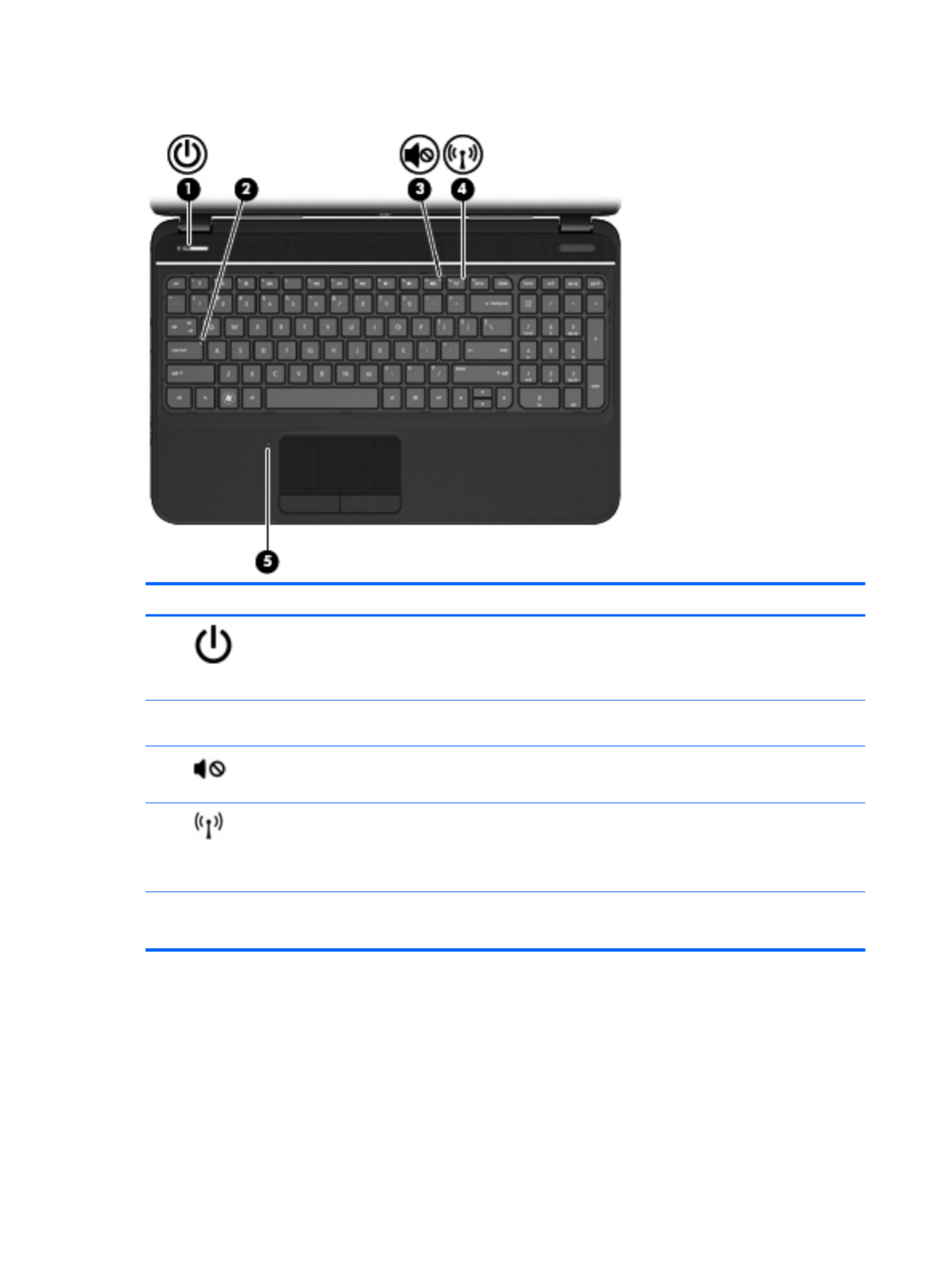
Lights
Component Description
(1) Power light ●White: The computer is on.
●Blinking: The computer is in Sleep mode.
●Off: The computer is off or in Hibernation mode.
(2) Caps lock light White: Caps lock is on, which switches the keys to all capital
letters.
(3) Mute light ●Amber: Computer sound is off.
●Off: Computer sound is on.
(4) Wireless light ●White: An integrated wireless device, such as a
wireless local area network (WLAN) device and/or a
Bluetooth® device, is on.
●Amber: All wireless devices are off.
(5) TouchPad light ●Amber: The TouchPad is off.
●Off: The TouchPad is on.
8 Chapter 2 External component identification

TouchPad
Component Description
(1) TouchPad on/off button Turns the TouchPad on or off.
(2) TouchPad light ●Amber: The TouchPad is off.
●Off: The TouchPad is on.
(3) TouchPad zone Moves the on-screen pointer and selects or activates items
on the screen.
(4) Left TouchPad button Functions like the left button on an external mouse.
(5) Right TouchPad button Functions like the right button on an external mouse.
Top 9
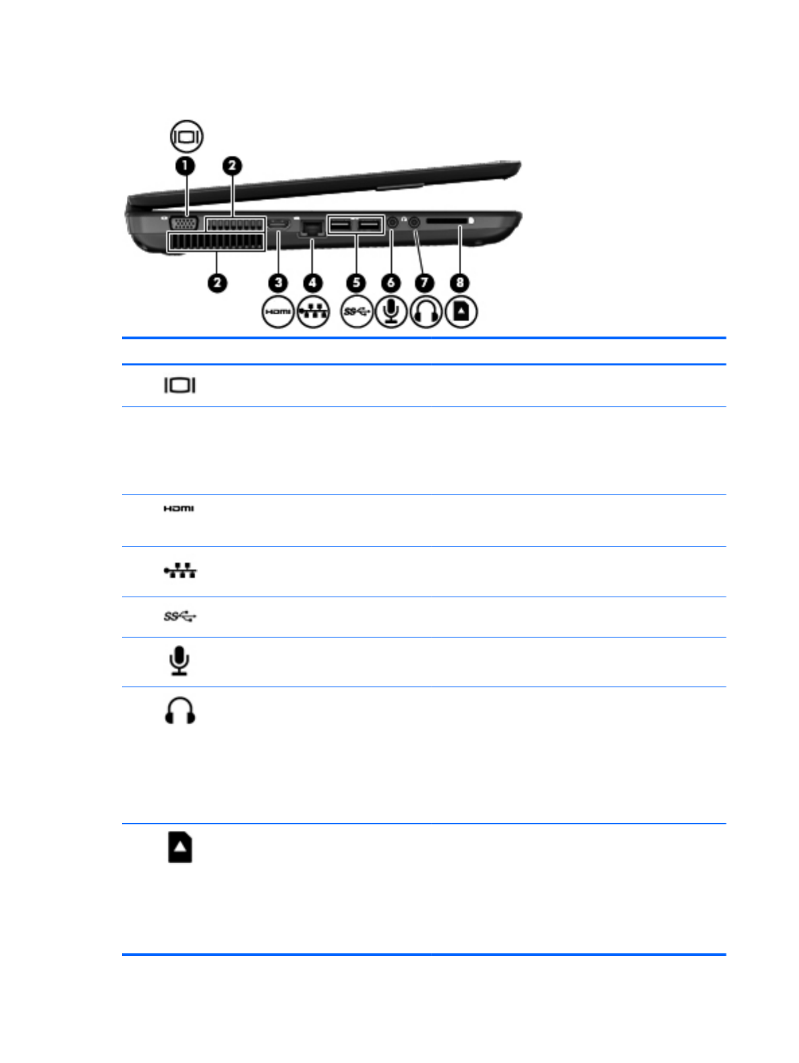
Left side
Component Description
(1) External monitor port Connects an external VGA monitor or projector.
(2) Vents (2) Enable airflow to cool internal components.
NOTE: The computer fan starts up automatically to cool
internal components and prevent overheating. It is normal
for the internal fan to cycle on and off during routine
operation.
(3) HDMI port Connects an optional video or audio device, such as a
high-definition television, or any compatible digital or audio
device.
(4) RJ-45 (network) jack Connects a network cable.
(5) USB 3.0 ports (2) Connect optional USB 3.0 compatible devices and provide
enhanced USB power performance.
(6) Audio-in (microphone) jack Connects an optional computer headset microphone,
stereo array microphone, or monaural microphone.
(7) Audio-out (headphone) jack Connects optional powered stereo speakers, headphones,
earbuds, a headset, or a television audio cable.
WARNING! To reduce the risk of personal injury, adjust
the volume before using headphones, earbuds, or a
headset. For additional safety information, see the
Regulatory, Safety and Environmental Notices.
NOTE: When a device is connected to a headphone jack,
the computer speakers are disabled.
(8) Digital media slot Supports the following digital card formats:
●Secure Digital (SD) Memory Card
●Secure Digital Extended Capacity (SDxC) Memory
Card
●Secure Digital High Capacity (SDHC) Memory Card
●MultiMediaCard (MMC)
10 Chapter 2 External component identification
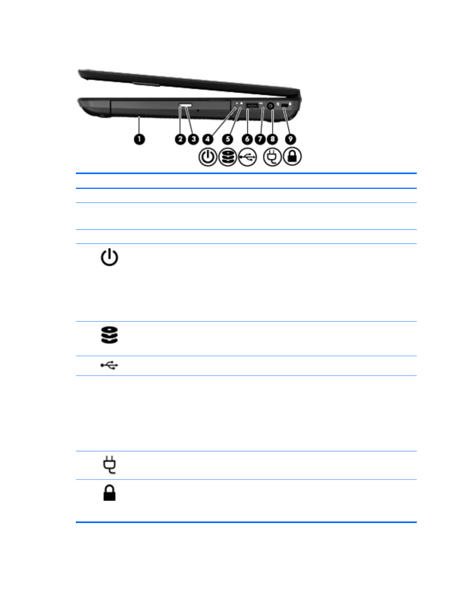
Right side
Component Description
(1) Optical drive Reads and writes to an optical disc.
(2) Optical drive light ●Green or amber: The optical drive is being accessed.
●Off: The optical drive is idle.
(3) Optical drive eject button Releases the disc tray.
(4) Power light ●White: The computer is on.
●Blinking white: The computer is in the Sleep state,
which is an energy-saving mode. The computer shuts
off power to the display and other unneeded
components.
●Off: The computer is off or in Hibernation. Hibernation
is an energy-saving mode that uses the least amount
of power.
(5) Hard drive light ●Blinking white: The hard drive is being accessed.
●Amber: HP 3D DriveGuard has temporarily parked the
hard drive.
(6) USB 2.0 port Connects an optional USB 2.0 compatible device.
(7) AC adapter light ●White: The AC adapter is connected and the battery is
charged.
●Blinking white: The battery has reached a low battery
level.
●Amber: The AC adapter is connected and the battery
is charging.
●Off: The computer is using DC power.
(8) Power connector Connects an AC adapter.
(9) Security cable lock slot Attaches an optional security cable to the computer.
NOTE: The security cable is designed to act as a
deterrent, but it may not prevent the computer from being
mishandled or stolen.
Right side 11
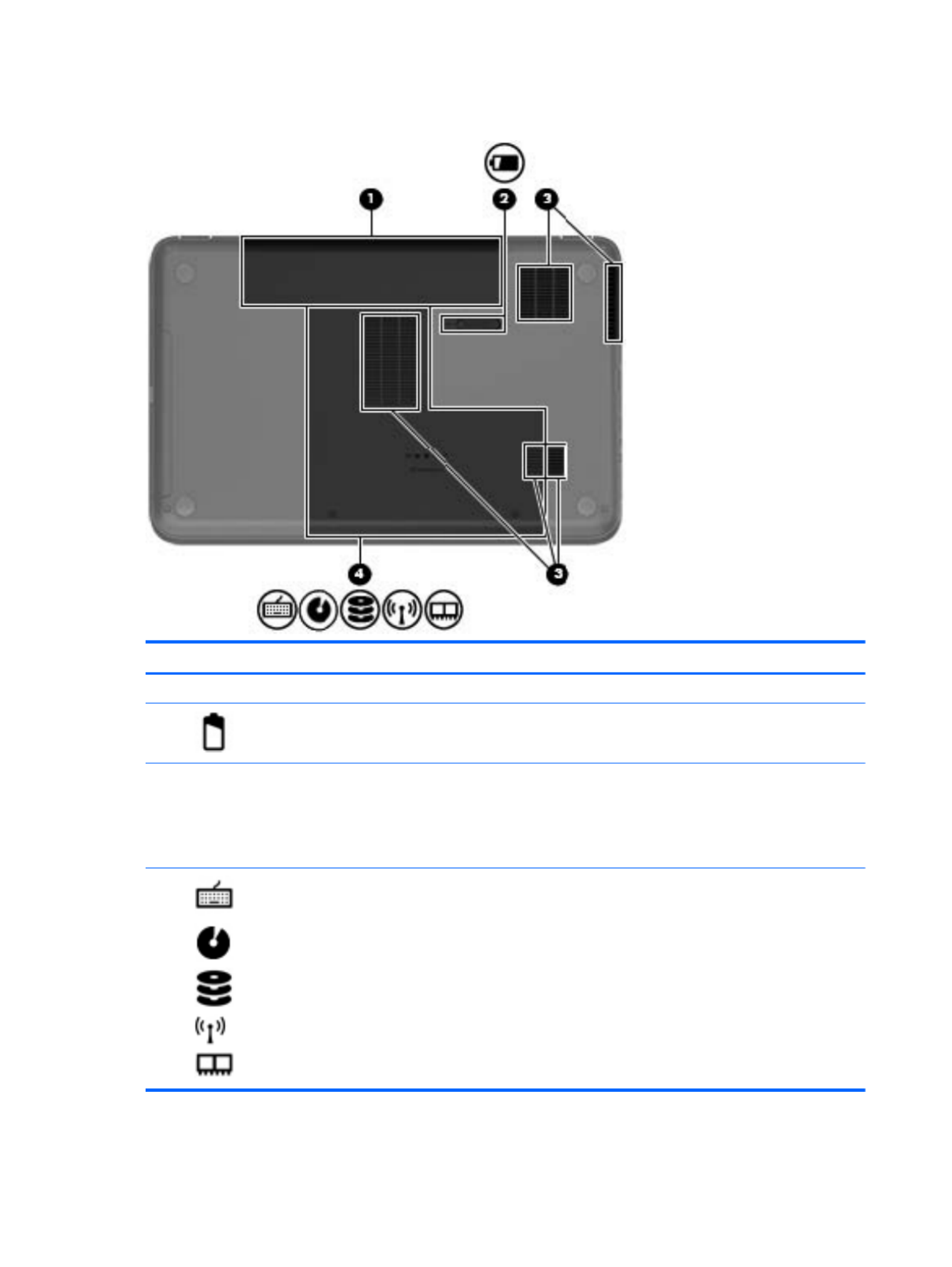
Bottom components
Component Description
(1) Battery bay Holds the battery.
(2) Battery release latch Releases the battery from the battery bay.
(3) Vents (5) Enable airflow to cool internal components.
NOTE: The computer fan starts up automatically to cool
internal components and prevent overheating. It is normal
for the internal fan to cycle on and off during routine
operation.
(4) Service door Provides access to the keyboard, optical drive, hard drive,
wireless module, and memory modules.
CAUTION: To prevent an unresponsive system, replace
the wireless module only with a wireless module authorized
for use in the computer by the governmental agency that
regulates wireless devices in your country or region. If you
replace the module and then receive a warning message,
remove the module to restore computer functionality, and
then contact customer support through Help and Support.
12 Chapter 2 External component identification

3 Illustrated parts catalog
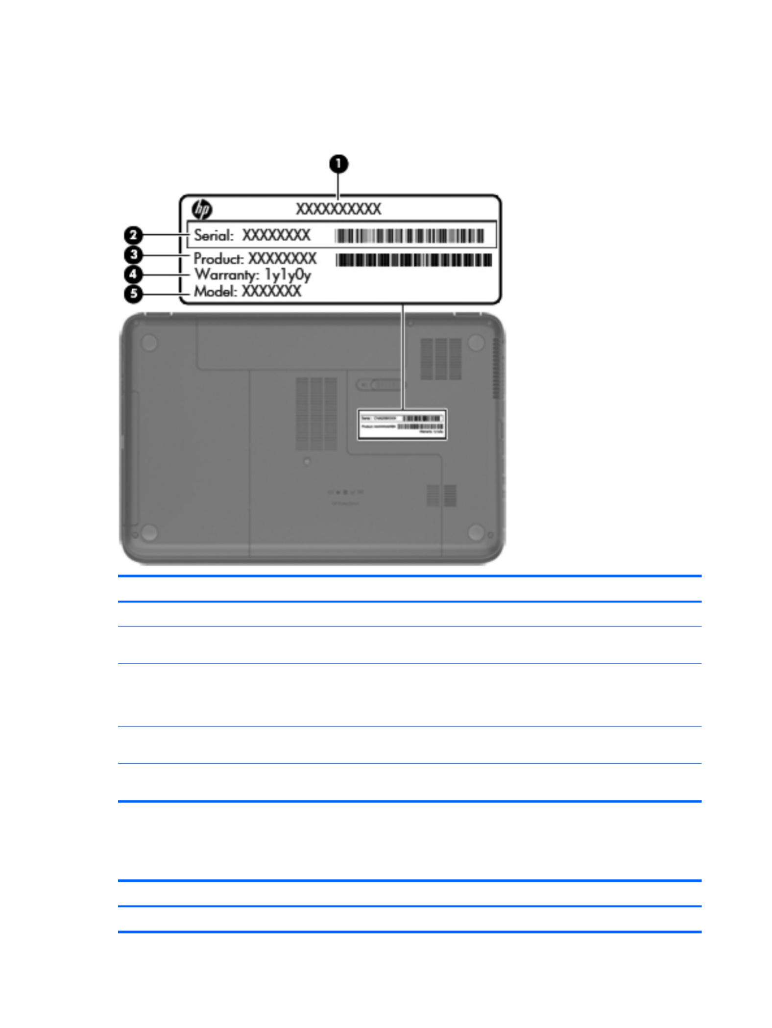
Serial number location
When ordering parts or requesting information, provide the computer serial number and model
number located in the battery bay of the computer.
Component Description
(1) Product name The name affixed to the front of the computer.
(2) Serial number (s/n) An alphanumeric identifier that is unique to each product.
(3) Product number This number provides specific information about the product’s
hardware components. The product number helps a service
technician to determine what components and parts are needed.
(4) Warranty period The duration of the warranty period for the computer.
(5) Model description (select models only) An alphanumeric identifier used to locate documents, drivers, and
support for the computer.
Serial number location 13

Computer major components
14 Chapter 3 Illustrated parts catalog

Item Description Spare part number
(1) 39.6 cm (15.6 in) High Definition (HD), LED, BrightView (1366×768) display
assembly
NOTE: For more display assembly internal component spare part information, see
Display assembly subcomponents on page 18.
(2) Keyboard (includes keyboard cable):
●For use in the United States, Black 681800-001
●For use in the United Kingdom, Black 681800-031
●For use in Germany, Black 681800-041
●For use in France, Black 681800-051
●For use in Italy, Black 681800-061
●For use in Spain, Black 681800-071
●For use in Portugal, Black 681800-131
●For use in Turkey, Black 681800-141
●For use in Greece, Black 681800-151
●For use in Saudi Arabia, Black 681800-171
●For use in Hungary, Black 681800-211
●For use in Russia, Black 681800-251
●For use in Bulgaria, Black 681800-261
●For use in Romania, Black 681800-271
●For use in Thailand, Black 681800-281
●For use in Japan, Black 681800-291
●For use in Europe, Black 681800-A41
●For use in Taiwan, Black 681800-AB1
●For use in Korea, Black 681800-AD1
●For International use, Black 681800-B31
●For use in the Adriatics, Black 681800-BA1
●For use in Israel, Black 681800-BB1
●For use in Switzerland, Black 681800-BG1
●For use in the Netherlands, Black 681800-DH1
●For use in the Adriatics, Black 681800-FL1
●For use in Canada, Black 681800-DB1
(3) Top cover (includes TouchPad board):
●For use in Ruby red computer models 681823-001
●For use in Winter blue computer models 681824-001
●For use in Sparkling black computer models 681825-001
Computer major components 15

Item Description Spare part number
(4) Power button board (includes cable) 683549-001
(5) TouchPad LED board (includes cable) 684061-001
(6) TouchPad button board (includes cable) 683548-001
(7) Speaker assembly (includes cable) 681821-001
(8) System board (includes replacement thermal material):
●For use only with computer models equipped with UMA video memory 683029-001
●For use only with computer models equipped with 1024 MB of dedicated discrete
video memory
683030-001
●For use only with computer models equipped with 2048 MB of dedicated discrete
video memory
683031-001
(9) Platform Controller Hub (PCH) heat sink 683843-001
(10) Processor (includes replacement thermal material):
●AMD A10-4600M processor (3.2 GHz/2.3 GHz, 1600 MHz/4.0 MB L2 cache, DDR3,
quad core, 35W)
683046-001
●AMD A8-4500M processor (2.8 GHz/1.9 GHz, 1600 MHz/4.0 MB L2 cache, DDR3,
quad core, 35W)
683048-001
●AMD A6-4400M processor (3.2 GHz/2.7 GHz, 1600 MHz/1.0 MB L2 cache, DDR3,
dual core, 35W)
683047-001
(11) RTC battery (includes mounting adhesive) 637193-001
(12) Heat sink assembly (includes replacement thermal material):
●For use in AMD UMA computer models 683027-001
●For use in AMD discrete computer models 683028-001
●Fan (available separately) 680551-001
(13) Power connector (includes cable) 682744-001
(14) USB board (includes cable) 683547-001
(15) Optical drive cable 682742-001
(16) Battery:
●6 cell Li-ion, 2.20 Ah, 47 Wh 593553-001
●6 cell Li-ion, 2.55 Ah, 55 Wh 593554-001
(17) Base enclosure 681805-001
(18) Hard drive:
Supports the following 9.5 mm, 6.35 cm (2.5 in) SATA hard drives:
●1 TB, 5400 rpm 676521-001
●750 GB, 7200 rpm 633252-001
●750 GB, 5400 rpm 633250-001
●640 GB, 5400 rpm 669300-001
16 Chapter 3 Illustrated parts catalog

Item Description Spare part number
●500 GB, 7200 rpm 634925-001
●500 GB, 5400 rpm 669299-001
●320 GB, 7200 rpm 641672-001
●320 GB, 5400 rpm 622643-001
Supports the following 7.0 mm, 6.35 cm (2.5 in) SATA hard drives:
●320 GB, 7200 rpm 634862-001
●320 GB, 5400 rpm 645193-001
●Hard Drive Hardware Kit (not illustrated, includes hard drive cable, hard drive
bumpers, and hard drive bracket and screws)
682745-001
(19) Memory modules (1066 MHz, DDR3):
●4 GB PC3 12800 1600 MHz shared 641369-001
●2 GB PC3 12800 1600 MHz shared 652972-001
(20) Wireless (WLAN) module:
●Atheros 9485GN 802.11b/g/n 1×1 WiFi Adapter and 3012 Bluetooth 4.0 Combo
Adapter (select models only)
655795-001
●Broadcom 4313GN 802.11b/g/n 1×1 WiFi Adapter and 20702 Bluetooth 4.0+HS
Combo Adapter
657325-001
●Ralink RT5390R 802.11b/g/n 1×1 WiFi Adapter 670691-001
●Atheros HB125 802.11b/g/n 1×1 WiFi Adapter (select models only) 675794-001
(21) Optical drive (includes optical drive bezel and bracket):
●DVD±RW and CD-RW SuperMulti Double-Layer Combo Drive 681814-001
●Blu-ray Disc ROM and DVD±R/RW SuperMulti Double-Layer Drive 681815-001
(22) Service Door (included in Plastics kit) 681816-001
Rubber Kit (not illustrated, includes rubber feet) 680563-001
Computer major components 17

Display assembly subcomponents
Item Description Spare part number
(1) Display bezel 681806-001
(2) Webcam/microphone module 680577-001
(3) Display hinge kit (includes left and right display hinges and brackets) 681812-001
(4) 39.6 cm (15.6 in) high-definition, BrightView LED display panel 681817-001
(5) Wireless antenna (includes wireless antenna transceivers and cable) 681813-001
(6) Display cable (included in the Display Cable Kit) 681808-001
(7) Display hinge covers 681811-001
(8) Display back cover (includes logo):
●For use in Ruby red computer models 681802-001
●For use in Winter blue computer models 681803-001
●For use in Sparkling black computer models 681804-001
Display Screw Kit (not illustrated) 681819-001
18 Chapter 3 Illustrated parts catalog

Mass storage devices
Item Description Spare part number
(1) Optical drive (12.7 mm, SATA, fixed, includes bezel and bracket)
●Blu-ray ROM DVD±R/RW Super Multi Double-Layer Drive 681814-001
●DVD±RW and CD-RW Super Multi Double-Layer Combo Drive 681815-001
●Optical drive cable 682742-001
(2) Hard drive
Supports the following 9.50 mm, 6.35 cm (2.50 in) SATA hard drives:
●1 TB, 5400 rpm 676521-001
●750 GB, 7200 rpm 633252-001
●750 GB, 5400 rpm 634250-001
●640 GB, 5400 rpm 669300-001
●500 GB, 7200 rpm 634925-001
●500 GB, 5400 rpm 669299-001
●320 GB, 7200 rpm 641672-001
●320 GB, 5400 rpm 622643-001
Supports the following 7.00 mm, 6.35 cm (2.50 in) SATA hard drives:
●320 GB, 7200 rpm 634862-001
●320 GB, 5400 rpm 645193-001
Hard drive hardware kit (includes hard drive cable, hard drive bumpers, and hard
drive bracket and screws)
682745-001
Mass storage devices 19

Miscellaneous parts
Description Spare part number
AC adapters
●90 W HP Smart AC adapter with Power Factor Correction (PFC) (for computer models
equipped with a graphics subsystem with discrete memory only)
609940-001
●65 W HP Smart AC adapter with PFC (for computer models equipped with a graphics
subsystem with UMA memory only)
609939-001
●90 W HP Smart AC adapter with PFC (for select computer models equipped with a graphics
subsystem with discrete memory only)
609947-001
●65 W HP Smart AC adapter (for select computer models equipped with a graphics subsystem
with UMA memory only)
609948-001
Power cord, AC, 3 wire, black, 1.83 m
●For use in North America 490371-001
●For use in Australia 490371-011
●For use in Europe 490371-021
●For use in the United Kingdom and Singapore 490371-031
●For use in Italy 490371-061
●For use in Denmark 490371-081
●For use in Switzerland 490371-111
●For use in Japan 490371-291
●For use in the People's Republic of China 490371-AA1
●For use in Taiwan 490371-AB1
●For use in South Korea 490371-AD1
●For use in South Africa 490371-AR1
●For use in Israel 490371-BB1
●For use in India 490371-D61
Thermal pad 680571-001
Display screw kit 681819-001
Screw kit 681820-001
20 Chapter 3 Illustrated parts catalog

Sequential part number listing
Spare part number Description
490371-001 Power cord, AC, 3 wire, black, 1.83 m for use in North America
490371-011 Power cord, AC, 3 wire, black, 1.83 m for use in Australia
490371-021 Power cord, AC, 3 wire, black, 1.83 m for use in Europe
490371-031 Power cord, AC, 3 wire, black, 1.83 m for use in the United Kingdom and Singapore
490371-061 Power cord, AC, 3 wire, black, 1.83 m for use in Italy
490371-081 Power cord, AC, 3 wire, black, 1.83 m for use in Denmark
490371-111 Power cord, AC, 3 wire, black, 1.83 m for use in Switzerland
490371-291 Power cord, AC, 3 wire, black, 1.83 m for use in Japan
490371-AA1 Power cord, AC, 3 wire, black, 1.83 m for use in the People's Republic of China
490371-AB1 Power cord, AC, 3 wire, black, 1.83 m for use in Taiwan
490371-AD1 Power cord, AC, 3 wire, black, 1.83 m for use in Korea
490371-AR1 Power cord, AC, 3 wire, black, 1.83 m for use in South Africa
490371-BB1 Power cord, AC, 3 wire, black, 1.83 m for use in Israel
490371-D61 Power cord, AC, 3 wire, black, 1.83 m for use in India
593553-001 Battery, 6 cell, 2.20 Ah, 47 Wh
593554-001 Battery, 6-cell, 2.55 Ah, 55 Wh
609939-001 65 W AC adapter
609940-001 90 W AC adapter
609947-001 90 W AC adapter (EM)
609948-001 65 W AC adapter (EM)
622643-001 320 GB, 5400 rpm hard drive
633252-001 750 GB, 7200 rpm hard drive
634250-001 750 GB, 5400 rpm hard drive
634862-001 320 GB, 7200 rpm hard drive
634925-001 500 GB, 7200 rpm hard drive
637193-001 RTC battery (includes mounting adhesive)
641369-001 4 GB (PC3, 12800, 1600 MHz) memory module
641672-001 320 GB, 7200 rpm hard drive
645193-001 320 GB, 5400 rpm hard drive
652972-001 2 GB (PC3, 12800, 1600 MHz) memory module
655795-001 WLAN Atheros 9485GN 802.11b/g/n 1×1 WiFi Adapter and 3012 Bluetooth 4.0 Combo Adapter
(select models only
656120-001 WLAN Ralink RT5390BC8 802.11b/g/n 1×1 WiFi and Bluetooth 3.0+HS Combo Adapter
Sequential part number listing 21

Spare part number Description
657325-001 WLAN Broadcom 4313GN 802.11b/g/n 1×1 WiFi Adapter and 20702 Bluetooth 4.0+HS Combo
Adapter
669299-001 500 GB, 5400 rpm hard drive
669300-001 640 GB, 5400 rpm hard drive
670691-001 WLAN Ralink RT5390R 802.11b/g/n 1×1 WiFi Adapter
675794-001 WLAN Atheros HB125 802.11b/g/n 1×1 WiFi Adapter (select models only)
676521-001 1 TB, 5400 rpm hard drive
680551-001 Fan
680563-001 Rubber Kit (includes rubber feet)
680571-001 Thermal Material Kit (includes replacement thermal paste and pads)
680577-001 Webcam/microphone module
681800-001 Keyboard for use in the United States, black
681800-031 Keyboard for use in the United Kingdom, black
681800-041 Keyboard for use in Germany, black
681800-051 Keyboard for use in France, black
681800-061 Keyboard for use in Italy, black
681800-071 Keyboard for use in Spain, black
681800-131 Keyboard for use in Portugal, black
681800-141 Keyboard for use in Turkey, black
681800-151 Keyboard for use in for use in Greece, Black
681800-171 Keyboard for use in Saudi Arabia, black
681800-211 Keyboard for use in Hungary, black
681800-251 Keyboard for use in Russia, black
681800-261 Keyboard for use in Bulgaria, black
681800-271 Keyboard for use Romania, black
681800-291 Keyboard for use in Japan, black
681800-A41 Keyboard for use in Europe, black
681800-AB1 Keyboard for use in Taiwan, black
681800-AD1 Keyboard for use in Korea, black
681800-B31 Keyboard for International use, black
681800-BA1 Keyboard for use in the Adriatics, black
681800-BB1 Keyboard for use in Israel, black
681800-BG1 Keyboard for use in Switzerland, black
681800-DB1 Keyboard for use in Canada, black
681800-DH1 Keyboard for use in the Netherlands, black
22 Chapter 3 Illustrated parts catalog

Spare part number Description
681800-FL1 Keyboard for use in the Adriatics, black
681802-001 Display back cover for use in Ruby red computer models
681803-001 Display back cover for use in Winter blue computer models
681804-001 Display back cover for use in Sparkling black computer models
681805-001 Base enclosure
681806-001 Display Bezel
681808-001 Display cable
681811-001 Display hinge covers
681812-001 Display bracket (with hinges)
681813-001 Wireless antenna (includes wireless antenna transceivers and cable)
681814-001 Blu-ray ROM DVD±R/RW Super Multi Double-Layer Drive
681815-001 DVD±RW and CD-RW Super Multi Double-Layer Combo Drive
681816-001 Service Door (included in Plastics kit)
681817-001 39.6 cm (15.6 in) high-definition, BrightView LED display panel
681819-001 Display screw kit
681820-001 Screw kit
681821-001 Speaker assembly (includes cable)
681823-001 Top cover for use in Ruby red computer models
681824-001 Top cover for use in Winter blue computer models
681825-001 Top cover for use in Sparkling black computer models
682742-001 Optical drive cable
682744-001 Power connector
682745-001 Hard drive hardware kit (includes hard drive cable, hard drive bumpers, and hard drive bracket and
screws)
683027-001 Heat sink for use only with computer models equipped with UMA video memory
683028-001 Heat sink for use only with computer models equipped with discrete video memory
683029-001 System board for use only with computer models equipped with UMA video memory (includes
replacement thermal material)
683030-001 System board for use only with computer models equipped with a graphics subsystem with 1 GB of
switchable discrete video memory (includes replacement thermal material)
683031-001 System board for use only with computer models equipped with a graphics subsystem with 2 GB of
switchable discrete video memory (includes replacement thermal material)
683046-001 AMD A10-4600M processor (3.2 GHz/2.3 GHz, 1600 MHz/4.0 MB L2 cache, DDR3, quad core, 35W)
683047-001 AMD A8-4500M processor (3.2 GHz/2.1 GHz, 1600 MHz/1.0 MB L2 cache, DDR3, quad core, 35W)
683048-001 AMD A6-4400M processor (3.0 GHz/2.6 GHz, 1600 MHz/4.0 MB L2 cache, DDR3, dual core, 35W)
683547-001 USB board (includes cable)
Sequential part number listing 23

Spare part number Description
683548-001 TouchPad button board
683549-001 Power button board
683843-001 PCH heat sink
684061-001 TouchPad LED board
24 Chapter 3 Illustrated parts catalog

4 Removal and replacement procedures
Preliminary replacement requirements
Tools required
You will need the following tools to complete the removal and replacement procedures:
●Flat-bladed screwdriver
●Magnetic screwdriver
●Phillips P0 and P1 screwdrivers
Service considerations
The following sections include some of the considerations that you must keep in mind during
disassembly and assembly procedures.
NOTE: As you remove each subassembly from the computer, place the subassembly (and all
accompanying screws) away from the work area to prevent damage.
Plastic parts
CAUTION: Using excessive force during disassembly and reassembly can damage plastic parts.
Use care when handling the plastic parts. Apply pressure only at the points designated in
the maintenance instructions.
Cables and connectors
CAUTION: When servicing the computer, be sure that cables are placed in their proper locations
during the reassembly process. Improper cable placement can damage the computer.
Cables must be handled with extreme care to avoid damage. Apply only the tension required to
unseat or seat the cables during removal and insertion. Handle cables by the connector whenever
possible. In all cases, avoid bending, twisting, or tearing cables. Be sure that cables are routed in
such a way that they cannot be caught or snagged by parts being removed or replaced. Handle flex
cables with extreme care; these cables tear easily.
Preliminary replacement requirements 25

Drive handling
CAUTION: Drives are fragile components that must be handled with care. To prevent damage to
the computer, damage to a drive, or loss of information, observe these precautions:
Before removing or inserting a hard drive, shut down the computer. If you are unsure whether
the computer is off or in Hibernation, turn the computer on, and then shut it down through
the operating system.
Before handling a drive, be sure that you are discharged of static electricity. While handling a drive,
avoid touching the connector.
Before removing a diskette drive or optical drive, be sure that a diskette or disc is not in the drive and
be sure that the optical drive tray is closed.
Handle drives on surfaces covered with at least one inch of shock-proof foam.
Avoid dropping drives from any height onto any surface.
After removing a hard drive, an optical drive, or a diskette drive, place it in a static-proof bag.
Avoid exposing an internal hard drive to products that have magnetic fields, such as monitors
or speakers.
Avoid exposing a drive to temperature extremes or liquids.
If a drive must be mailed, place the drive in a bubble pack mailer or other suitable form of protective
packaging and label the package “FRAGILE.”
Grounding guidelines
Electrostatic discharge damage
Electronic components are sensitive to electrostatic discharge (ESD). Circuitry design and structure
determine the degree of sensitivity. Networks built into many integrated circuits provide some
protection, but in many cases, ESD contains enough power to alter device parameters or melt
silicon junctions.
A discharge of static electricity from a finger or other conductor can destroy static-sensitive devices or
microcircuitry. Even if the spark is neither felt nor heard, damage may have occurred.
An electronic device exposed to ESD may not be affected at all and can work perfectly throughout a
normal cycle. Or the device may function normally for a while, then degrade in the internal layers,
reducing its life expectancy.
CAUTION: To prevent damage to the ng or instacomputer when you are removi lling internal
components, observe these precautions:
Keep components in their electrostatic-safe containers until you are ready to install them.
Before touching an electronic component, discharge static electricity by using the guidelines
described in this section.
Avoid touching pins, leads, and circuitry. Handle electronic components as little as possible.
If you remove a component, place it in an electrostatic-safe container.
The following table shows how humidity affects the electrostatic voltage levels generated by
different activities.
CAUTION: A product can be degraded by as little as 700 V.
26 Chapter 4 Removal and replacement procedures

Typical electrostatic voltage levels
Relative humidity
Event 10% 40% 55%
Walking across carpet 35,000 V 15,000 V 7,500 V
Walking across vinyl floor 12,000 V 5,000 V 3,000 V
Motions of bench worker 6,000 V 800 V 400 V
Removing DIPS from plastic tube 2,000 V 700 V 400 V
Removing DIPS from vinyl tray 11,500 V 4,000 V 2,000 V
Removing DIPS from Styrofoam 14,500 V 5,000 V 3,500 V
Removing bubble pack from PCB 26,500 V 20,000 V 7,000 V
Packing PCBs in foam-lined box 21,000 V 11,000 V 5,000 V
Preliminary replacement requirements 27

Packaging and transporting guidelines
Follow these grounding guidelines when packaging and transporting equipment:
●To avoid hand contact, transport products in static-safe tubes, bags, or boxes.
●Protect ESD-sensitive parts and assemblies with conductive or approved containers or
packaging.
●Keep ESD-sensitive parts in their containers until the parts arrive at static-free workstations.
●Place items on a grounded surface before removing items from their containers.
●Always be properly grounded when touching a component or assembly.
●Store reusable ESD-sensitive parts from assemblies in protective packaging or
nonconductive foam.
●Use transporters and conveyors made of antistatic belts and roller bushings. Be sure that
mechanized equipment used for moving materials is wired to ground and that proper materials
are selected to avoid static charging. When grounding is not possible, use an ionizer to dissipate
electric charges.
Workstation guidelines
Follow these grounding workstation guidelines:
●Cover the workstation with approved static-shielding material.
●Use a wrist strap connected to a properly grounded work surface and use properly grounded
tools and equipment.
●Use conductive field service tools, such as cutters, screwdrivers, and vacuums.
●When fixtures must directly contact dissipative surfaces, use fixtures made only of static-
safe materials.
●Keep the work area free of nonconductive materials, such as ordinary plastic assembly aids
and Styrofoam.
●Handle ESD-sensitive components, parts, and assemblies by the case or PCM laminate. Handle
these items only at static-free workstations.
●Avoid contact with pins, leads, or circuitry.
●Turn off power and input signals before inserting or removing connectors or test equipment.
28 Chapter 4 Removal and replacement procedures

Equipment guidelines
Grounding equipment must include either a wrist strap or a foot strap at a grounded workstation.
●When seated, wear a wrist strap connected to a grounded system. Wrist straps are flexible
straps with a minimum of one megohm ±10% resistance in the ground cords. To provide proper
ground, wear a strap snugly against the skin at all times. On grounded mats with banana-plug
connectors, use alligator clips to connect a wrist strap.
●When standing, use foot straps and a grounded floor mat. Foot straps (heel, toe, or boot straps)
can be used at standing workstations and are compatible with most types of shoes or boots. On
conductive floors or dissipative floor mats, use foot straps on both feet with a minimum of one
megohm resistance between the operator and ground. To be effective, the conductive must be
worn in contact with the skin.
The following grounding equipment is recommended to prevent electrostatic damage:
●Antistatic tape
●Antistatic smocks, aprons, and sleeve protectors
●Conductive bins and other assembly or soldering aids
●Nonconductive foam
●Conductive tabletop workstations with ground cords of one megohm resistance
●Static-dissipative tables or floor mats with hard ties to the ground
●Field service kits
●Static awareness labels
●Material-handling packages
●Nonconductive plastic bags, tubes, or boxes
●Metal tote boxes
●Electrostatic voltage levels and protective materials
The following table lists the shielding protection provided by antistatic bags and floor mats.
Material Use Voltage protection level
Antistatic plastics Bags 1,500 V
Carbon-loaded plastic Floor mats 7,500 V
Metallized laminate Floor mats 5,000 V
Component replacement procedures
This chapter provides removal and replacement procedures.
There are as many as 63 screws that must be removed, replaced, or loosened when servicing
the computer. Make special note of each screw and screw lock size and location during removal
and replacement.
Component replacement procedures 29
Service label
When ordering parts or requesting information, provide the computer serial number and model
number provided on the service label.
Item Description Function
(1) Product name The name affixed to the front of the computer.
(2) Serial number (s/n) This is an alphanumeric identifier that is unique to
each product.
(3) Part number/Product number (p/n) This number provides specific information about
the product's hardware components. The part
number helps a service technician to determine
what components and parts are needed.
(4) Warranty period This number describes the duration of the warranty
period for the computer.
(5) Model description (select models only) This is the alphanumeric identifier needed to locate
documents, drivers, and support for the computer.
Computer feet
Description Spare part number
Rubber feet kit 680563-001
30 Chapter 4 Removal and replacement procedures

The computer feet are adhesive-backed rubber pads. There are 4 rubber feet that attach to
the base enclosure in the locations illustrated below.
Component replacement procedures 31

Battery
Description Spare part number
6 cell, 55-Whr, 2.55-Ah Li-ion battery 593554-001
6 cell, 47-Whr, 2.20-Ah Li-ion battery 593553-001
Before disassembling the computer, follow these steps:
1. Shut down the computer. If you are unsure whether the computer is off or in Hibernation, turn
the computer on, and then shut it down through the operating system.
2. Disconnect all external devices connected to the computer.
3. Disconnect the power from the computer by first unplugging the power cord from the AC outlet
and then unplugging the AC adapter from the computer.
Remove the battery:
1. Slide the battery release latch (1) to release the battery.
2. Pivot the front edge of the battery (2) up and back.
3. Remove the battery (3) from the computer.
To insert the battery:
1. Align the tabs on the rear edge of the battery (1) with the notches on the rear edge of the battery
bay.
2. Pivot the front edge of the battery (2) down into the battery bay until it is seated. (The battery
release latch will automatically lock into place.)
32 Chapter 4 Removal and replacement procedures

Service door
Description Spare part number
Plastics kit (contains the service door) 681816-001
Before removing the service door, follow these steps:
1. Shut down the computer. If you are unsure whether the computer is off or in Hibernation, turn
the computer on, and then shut it down through the operating system.
2. Disconnect all external devices connected to the computer.
3. Disconnect the power from the computer by first unplugging the power cord from the AC outlet
and then unplugging the AC adapter from the computer.
4. Remove the battery (see Battery on page 32).
Remove the service door:
1. Using a small Phillips screwdriver, loosen the service door capture screw (1).
2. Slide the service door (2) forward slightly and lift the front right corner (3) to tilt the service door.
3. Remove the service door (4) at an angle.
Reverse this procedure to replace the service door.
Component replacement procedures 33

Optical drive
NOTE: The optical drive spare part kit includes a bezel and bracket.
Description Spare part number
Blu-ray ROM DVD±R/RW Super Multi Double-Layer Drive 681814-001
DVD±RW and CD-RW Super Multi Double-Layer Combo Drive 681815-001
Optical drive cable kit 682742-001
Before removing the optical drive, follow these steps:
1. Shut down the computer. If you are unsure whether the computer is off or in Hibernation, turn
the computer on, and then shut it down through the operating system.
2. Disconnect all external devices connected to the computer.
3. Disconnect the power from the computer by first unplugging the power cord from the AC outlet
and then unplugging the AC adapter from the computer.
4. Remove the battery (see Battery on page 32).
5. Remove the service door (see Service door on page 33).
Remove the optical drive:
1. Using a small Phillips screwdriver, remove the PM 2.5 x 6.5 screw (1) that secures the optical
drive to the computer.
2. Insert a screwdriver or other narrow tool through the release access hole (2) in the bottom of the
computer. Push the rear of the optical drive until it is released.
34 Chapter 4 Removal and replacement procedures
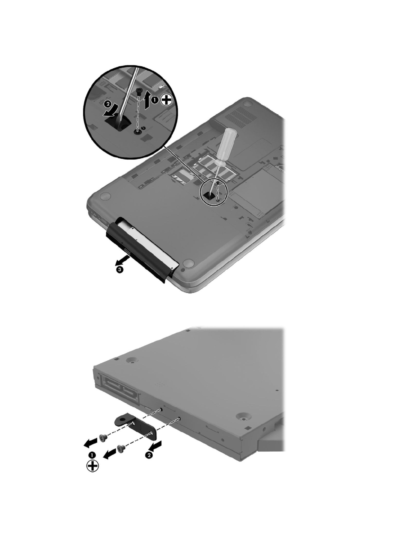
3. Pull the optical drive (3) out from the front until the optical drive is completely removed from the
computer.
4. Remove the 2 PM 2.0 x 3.0 screws (1) that secure the optical drive bracket to the optical drive
and then remove the bracket (2) from the optical drive.
5. Insert a straightened paper clip into the release access opening in the bezel.(1)
Component replacement procedures 35

6. Press the release tab (2) and remove the bezel from the tab side (3).
7. Remove the bezel (4) from the optical drive.
Reverse this procedure to reassemble and install the optical drive.
Hard drive
NOTE: The hard drive spare part kit does not include the hard drive cable, hard drive bumpers, or
hard drive bracket and screws.
Description Spare part number
Supports the following 9.50 mm, 6.35 cm (2.50 in) SATA hard drives:
1 TB, 5400 rpm 676521-001
750 GB, 7200 rpm 633252-001
750 GB, 5400 rpm 634250-001
640 GB, 5400 rpm 669300-001
500 GB, 7200 rpm 634925-001
500 GB, 5400 rpm 669299-001
320 GB, 7200 rpm 641672-001
320 GB, 5400 rpm 622643-001
Supports the following 7.00 mm, 6.35 cm (2.50 in) SATA hard drives:
320 GB, 7200 rpm 634862-001
320 GB, 5400 rpm 645193-001
Hard drive hardware kit (includes hard drive cable, hard drive bumpers, and hard drive bracket and
screws)
682745-001
36 Chapter 4 Removal and replacement procedures
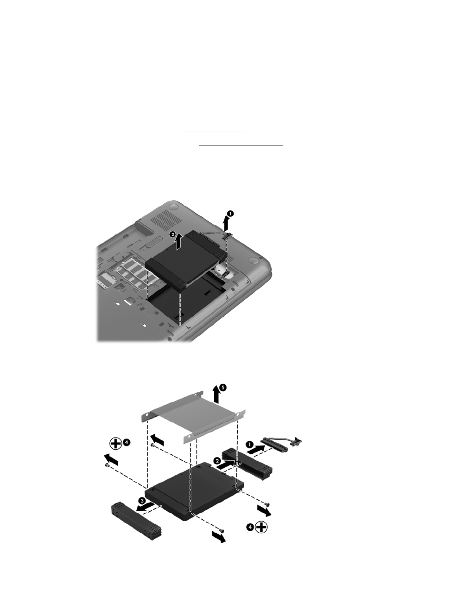
Before removing the hard drive, follow these steps:
1. Shut down the computer. If you are unsure whether the computer is off or in Hibernation, turn
the computer on, and then shut it down through the operating system.
2. Disconnect all external devices connected to the computer.
3. Disconnect the power from the computer by first unplugging the power cord from the AC outlet
and then unplugging the AC adapter from the computer.
4. Remove the battery (see Battery on page 32).
5. Remove the service door (see Service door on page 33).
Remove the hard drive:
1. Disconnect the hard drive cable (1) from the computer.
2. Lift the hard drive (2) to remove.
3. Disconnect the hard drive cable (1). Remove the front bumper (2) and back bumper (3).
4. Remove the 4 PM 3.0 x 3.5 screws (4), and then remove the bracket (5) from the hard drive.
Component replacement procedures 37

Replacing the hard drive
Reverse this procedure to reassemble and install the hard drive.
Memory module
WARNING! To reduce the risk of electric shock and damage to the equipment, unplug the power
cord and remove all batteries before installing a memory module.
CAUTION: Electrostatic discharge (ESD) can damage electronic components. Before beginning
any procedure, ensure that you are discharged of static electricity by touching a grounded metal
object.
NOTE: To use a dual-channel configuration with a second memory module, be sure that both
memory modules are identical.
Description Spare part number
4 GB (PC3, 12800, 1600 MHz) 641369-001
2 GB (PC3, 12800, 1600 MHz) 652972-001
Before removing a memory module, follow these steps:
CAUTION: To prevent information loss or an unresponsive system:
Shut down the computer before adding or replacing memory modules. Do not remove a memory
module while the computer is on, in the Sleep state, or in Hibernation.
1. Shut down the computer. If you are unsure whether the computer is off or in Hibernation, turn
the computer on, and then shut it down through the operating system.
2. Disconnect all external devices connected to the computer.
3. Disconnect the power from the computer by first unplugging the power cord from the AC outlet
and then unplugging the AC adapter from the computer.
4. Remove the battery (see Battery on page 32).
5. Remove the service door (see Service door on page 33).
To add or replace a memory module:
1. Spread the retention clips (1) on each side of the memory module slot to release the memory
module. (The memory module tilts up.)
38 Chapter 4 Removal and replacement procedures

2. Remove the memory module (2) by pulling it away from the slot at an angle.
CAUTION: To prevent damage to the memory module, hold the memory module by the edges
only. Do not touch the components on the memory module.
CAUTION: To protect a memory module after removal, place it in an electrostatic-safe
container.
3. Align the notched edge (1) of the memory module with the tab in the memory module slot.
4. With the memory module at a 45-degree angle from the surface of the memory module
compartment, press the module into the memory module slot (2) until it is seated.
Component replacement procedures 39
5. Gently press the memory module (3) down, applying pressure to both the left and right edges of
the module, until the retention clips snap into place.
40 Chapter 4 Removal and replacement procedures

WLAN module
Description Spare part number
Atheros 9485GN 802.11b/g/n 1×1 WiFi Adapter and 3012 Bluetooth 4.0 Combo Adapter (select
models only)
655795-001
Broadcom 4313GN 802.11b/g/n 1×1 WiFi Adapter and 20702 Bluetooth 4.0+HS Combo Adapter 657325-001
Ralink RT5390R 802.11b/g/n 1×1 WiFi Adapter 670691-001
Atheros HB125 802.11b/g/n 1×1 WiFi Adapter (select models only) 675794-001
CAUTION: To prevent an unresponsive system, replace the wireless module only with a wireless
module authorized for use in the computer by the governmental agency that regulates wireless
devices in your country or region. If you replace the module and then receive a warning message,
remove the module to restore device functionality, and then contact technical support.
Before removing the WLAN module, follow these steps:
1. Shut down the computer. If you are unsure whether the computer is off or in Hibernation, turn
the computer on, and then shut it down through the operating system.
2. Disconnect all external devices connected to the computer.
3. Disconnect the power from the computer by first unplugging the power cord from the AC outlet
and then unplugging the AC adapter from the computer.
4. Remove the battery (see Battery on page 32).
5. Remove the service door (see Service door on page 33).
Remove the WLAN module:
1. Disconnect the WLAN antenna cables (1) from the terminals on the WLAN module.
NOTE: The 1/black WLAN antenna cable is connected to the WLAN module 1/Main terminal.
The 2/gray WLAN antenna cable is connected to the WLAN module 2/Aux terminal.
2. Remove the PM 2.5 × 2.5 screw (2) that secures the WLAN module to the system board. (The
WLAN module tilts up.)
Component replacement procedures 41

3. Remove the WLAN module by pulling the module away from the slot at an angle (3).
NOTE: The WLAN module is designed with a notch to prevent incorrect installation into
the WLAN module socket.
Reverse this procedure to install the WLAN module.
42 Chapter 4 Removal and replacement procedures

Keyboard
NOTE: The keyboard spare part kit includes a keyboard cable.
Description Spare part number
Keyboard
●For use in the United States, Black 681800-001
●For use in the United Kingdom, Black 681800-031
●For use in Germany, Black 681800-041
●For use in France, Black 681800-051
●For use in Italy, Black 681800-061
●For use in Spain, Black 681800-071
●For use in Portugal, Black 681800-131
●For use in Turkey, Black 681800-141
●For use in Greece, Black 681800-151
●For use in Saudi Arabia, Black 681800-171
●For use in Hungary, Black 681800-211
●For use in Russia, Black 681800-251
●For use in Bulgaria, Black 681800-261
●For use in Romania, Black 681800-271
●For use in Japan, Black 681800-291
●For use in Europe, Black 681800-A41
●For use in Taiwan, Black 681800-AB1
●For use in Korea, Black 681800-AD1
●For International use, Black 681800-B31
●For use in Adriatics, Black 681800-BA1
●For use in Israel, Black 681800-BB1
●For use in Switzerland, Black 681800-BG1
●For use in Canada, Black 681800-DB1
●For use in the Netherlands, Black 681800-DH1
●For use in the Czech Republic and Slovakia, Black 681800-FL1
Before removing the keyboard, follow these steps:
1. Shut down the computer. If you are unsure whether the computer is off or in Hibernation, turn
the computer on, and then shut it down through the operating system.
2. Disconnect all external devices connected to the computer.
Component replacement procedures 43

3. Disconnect the power from the computer by first unplugging the power cord from the AC outlet
and then unplugging the AC adapter from the computer.
4. Remove the battery (see Battery on page 32).
5. Remove the service door (see Service door on page 33).
6. Remove the hard drive (see {Xref Error! Target does not exist.})
Remove the keyboard:
1. Remove the PM 2.5 × 6.5 screw that secures the keyboard to the computer.
2. Rest the computer on its left side.
3. Open the computer.
44 Chapter 4 Removal and replacement procedures

4. Using a thin, non-conductive tool, press on the back of the keyboard through the release access
hole until the keyboard disengages from the computer.
NOTE: The keyboard icon indicates the location of the keyboard release access hole.
5. Turn the computer right-side up with the front toward you.
6. Lift the rear edge of the keyboard (1), and then swing the keyboard (2) up and forward until it
rests upside down on the palm rest.
Component replacement procedures 45

7. Release the zero insertion force (ZIF) connector (1) to which the keyboard cable is attached, and
then disconnect the keyboard cable (2) from the system board.
8. Remove the keyboard.
Reverse this procedure to install the keyboard.
46 Chapter 4 Removal and replacement procedures

Top cover
NOTE: The top cover spare part kit includes the TouchPad.
Description Spare part number
Ruby red 681823-001
Winter blue 681824-001
Sparkling black 681825-001
Before removing the top cover, follow these steps:
1. Shut down the computer. If you are unsure whether the computer is off or in Hibernation, turn
the computer on, and then shut it down through the operating system.
2. Disconnect all external devices connected to the computer.
3. Disconnect the power from the computer by first unplugging the power cord from the AC outlet
and then unplugging the AC adapter from the computer.
4. Remove the battery (see Battery on page 32).
5. Remove the service door (see Service door on page 33).
6. Remove the optical drive (see Optical drive on page 34).
7. Remove the hard drive (see {Xref Error! Target does not exist.})
8. Remove the keyboard (see Keyboard on page 43).
When replacing the top cover, be sure that the following components are removed from the defective
top cover and installed on the replacement top cover:
●Power button board and cable (see Power button board on page 51).
●TouchPad button board and cable (see TouchPad button board on page 53).
●TouchPad LED board and cable (see TouchPad LED board on page 54).
●Speakers and cable (see Speakers on page 50).
Component replacement procedures 47

Remove the top cover:
1. Disconnect these cables from the system board:
(1) Power button board ZIF cable
(2) Speaker cable
(3) TouchPad button board ZIF cable
2. Remove the following screws under the keyboard:
(1) Five PM 2.5 x 4.0
(2) One PM 2.5 x 6.5
NOTE: This screw (2) also secures the speaker underneath the top cover.
3. Close the computer.
4. Turn the computer upside down, with the front toward you.
48 Chapter 4 Removal and replacement procedures
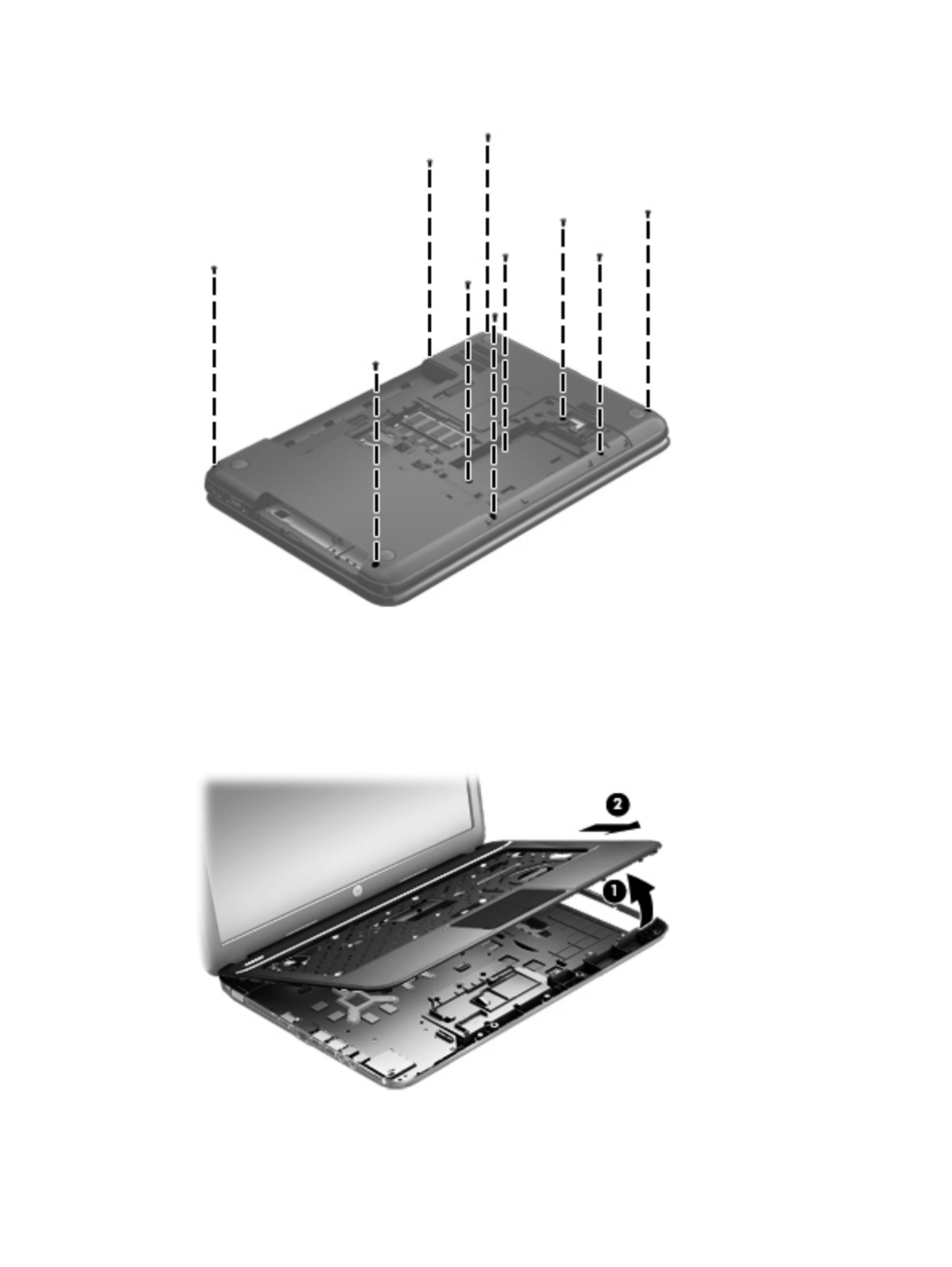
5. Remove the following ten PM 2.5 x 6.5 screws that secure the top cover to the computer.
6. Turn the computer right-side up, with the front toward you.
7. Open the computer.
8. Lift the front edge of the top cover (1) until the left and right sides disengage from
the base enclosure.
9. Remove the top cover (2).
Reverse this procedure to install the top cover.
Component replacement procedures 49

Speakers
Description Spare part number
Speaker Kit (includes left and right speakers and cable) 681821-001
Before removing the speakers, follow these steps:
1. Shut down the computer. If you are unsure whether the computer is off or in Hibernation, turn
the computer on, and then shut it down through the operating system.
2. Disconnect all external devices connected to the computer.
3. Disconnect the power from the computer by first unplugging the power cord from the AC outlet
and then unplugging the AC adapter from the computer.
4. Remove the battery (see Battery on page 32).
5. Remove the service door (see Service door on page 33).
6. Remove the optical drive (see Optical drive on page 34).
7. Remove the hard drive (see {Xref Error! Target does not exist.})
8. Remove the keyboard (see Keyboard on page 43).
9. Remove the top cover (see Top cover on page 47).
Remove the speakers:
1. There are two clips that hold the left speaker in place (1).
NOTE: A previously removed top cover screw also secures the right speaker in place.
2. Rotate and lift the left speaker from the top cover (2). Release the speaker cable from the clips
built into the top cover.
3. Remove one PM 2.5 x 3.5 screw (3) from the right speaker that secures it to the top cover (2).
NOTE: This screw also secures the power button board to the top cover.
50 Chapter 4 Removal and replacement procedures

4. Lift the speakers from the top cover (4).
Reverse this procedure to install the speakers.
Power button board
Description Spare part number
Power button board 683549–001
Before removing the power button board, follow these steps:
1. Shut down the computer. If you are unsure whether the computer is off or in Hibernation, turn
the computer on, and then shut it down through the operating system.
2. Disconnect all external devices connected to the computer.
3. Disconnect the power from the computer by first unplugging the power cord from the AC outlet
and then unplugging the AC adapter from the computer.
4. Remove the battery (see Battery on page 32).
5. Remove the service door (see Service door on page 33).
6. Remove the optical drive (see Optical drive on page 34).
7. Remove the hard drive (see {Xref Error! Target does not exist.})
8. Remove the keyboard (see Keyboard on page 43).
9. Remove the top cover (see Top cover on page 47).
10. Remove the speakers (see Speakers on page 50).
Component replacement procedures 51

Remove the power button board:
1. Turn the top cover upside down, with the front toward you.
NOTE: The power button board is secured by a screw that was previously removed when
releasing the speaker.
2. Release the tape securing the power button board cable and remove the power button board
and cable.
Reverse this procedure to install the power button board.
52 Chapter 4 Removal and replacement procedures

TouchPad button board
Description Spare part number
TouchPad button board (includes cable) 683548-001
Before removing the TouchPad button board, follow these steps:
1. Shut down the computer. If you are unsure whether the computer is off or in Hibernation, turn
the computer on, and then shut it down through the operating system.
2. Disconnect all external devices connected to the computer.
3. Disconnect the power from the computer by first unplugging the power cord from the AC outlet
and then unplugging the AC adapter from the computer.
4. Remove the battery (see Battery on page 32).
5. Remove the service door (see Service door on page 33).
6. Remove the optical drive (see Optical drive on page 34).
7. Remove the hard drive (see {Xref Error! Target does not exist.})
8. Remove the keyboard (see Keyboard on page 43).
9. Remove the top cover (see Top cover on page 47).
Remove the TouchPad button board and cable:
1. Turn the top cover upside down, with the front toward you.
2. Release the ZIF connector to which the TouchPad button board cable is connected, and then
disconnect the TouchPad button board cable (1) from the back of the TouchPad.
3. Remove the PM 2.5 x 2.5 screw (2) that secures the TouchPad button board cable to the top
cover.
4. Lift the front edge of the TouchPad button board (3) until it is released from the clips built into
the top cover.
Component replacement procedures 53
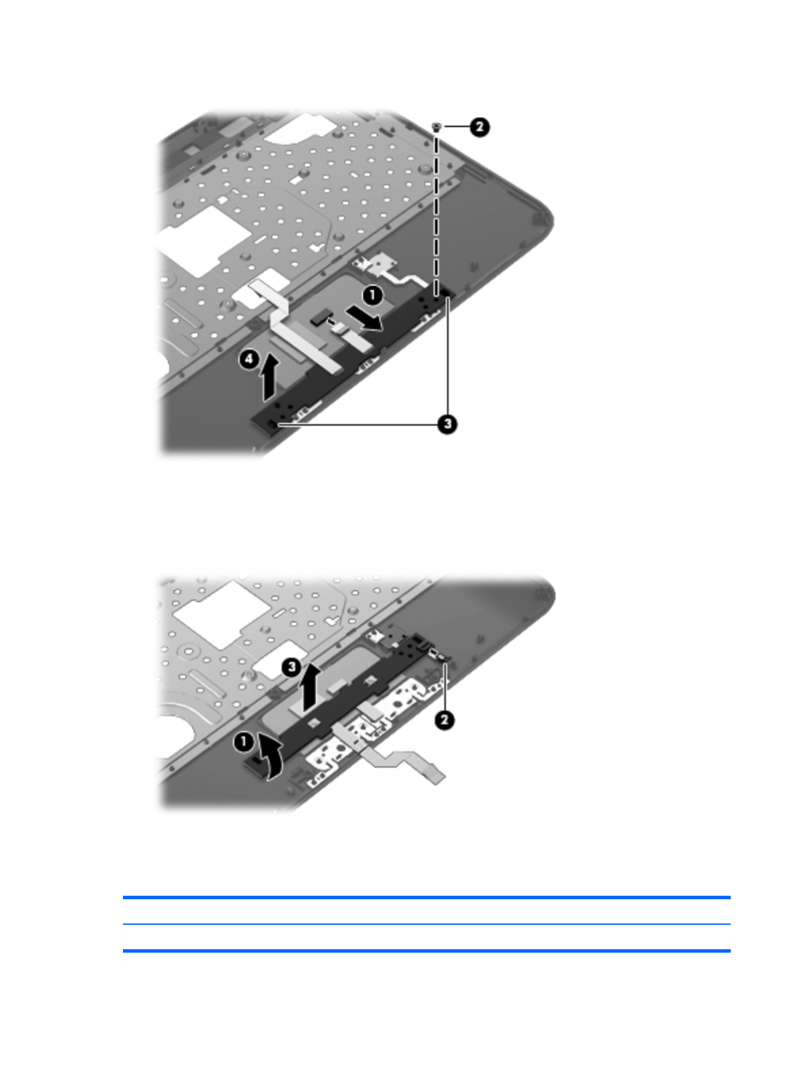
5. Lift the TouchPad button board (4) slightly to perform the next step.
6. Carefully invert the TouchPad button board (1).
7. Release the ZIF connector to which the TouchPad LED board cable is connected, and then
disconnect the TouchPad LED board cable (2) from the TouchPad button board.
8. Lift the TouchPad button board away from the top cover (3).
Reverse this procedure to install the TouchPad button board and cable.
TouchPad LED board
Description Spare part number
TouchPad LED board (includes cable) 684061-001
54 Chapter 4 Removal and replacement procedures

Before removing the TouchPad LED board, follow these steps:
1. Shut down the computer. If you are unsure whether the computer is off or in Hibernation, turn
the computer on, and then shut it down through the operating system.
2. Disconnect all external devices connected to the computer.
3. Disconnect the power from the computer by first unplugging the power cord from the AC outlet
and then unplugging the AC adapter from the computer.
4. Remove the battery (see Battery on page 32).
5. Remove the service door (see Service door on page 33).
6. Remove the optical drive (see Optical drive on page 34).
7. Remove the hard drive (see {Xref Error! Target does not exist.})
8. Remove the keyboard (see Keyboard on page 43).
9. Remove the top cover (see Top cover on page 47).
10. Remove the TouchPad button board (see TouchPad button board on page 53).
Remove the TouchPad LED board and cable:
1. Turn the top cover upside down, with the front toward you.
2. Apply slight pressure to the retention clips (1) of the top cover.
3. Lift the TouchPad LED board on the right front corner (2) up and away from the top cover.
4. Remove the TouchPad LED board and cable.
Reverse this procedure to install the TouchPad LED board and cable.
Component replacement procedures 55

Display assembly
Description Spare part number
Display back cover:
●Ruby red 681802-001
●Winter blue 681803-001
●Sparkling black 681804-001
Bezel 681806-001
Webcam/microphone module 680577-001
Hinge covers 681811-001
Display panel 681817-001
Display hinges. 681812-001
Display cable kit (includes webcam/microphone module cable) 681808-001
Antenna kit (includes the wireless antenna cables and transceivers). 681813-001
Before removing the display assembly, follow these steps:
1. Shut down the computer. If you are unsure whether the computer is off or in Hibernation, turn
the computer on, and then shut it down through the operating system.
2. Disconnect all external devices connected to the computer.
3. Disconnect the power from the computer by first unplugging the power cord from the AC outlet
and then unplugging the AC adapter from the computer.
4. Remove the battery (see Battery on page 32).
5. Remove the service door (see Service door on page 33).
6. Remove the optical drive (see Optical drive on page 34).
7. Remove the hard drive (see {Xref Error! Target does not exist.})
8. Remove the keyboard (see Keyboard on page 43).
9. Remove the top cover (see Top cover on page 47).
Remove the display assembly:
1. Disconnect the display panel cable (1) from the system board.
56 Chapter 4 Removal and replacement procedures

2. Release the wireless antenna cables (2) from the clips and the opening in the base enclosure.
NOTE: It may be necessary to release the USB board ZIF cable to remove the wireless
antenna cables.
CAUTION: Support the display assembly when removing the following screws. Failure to
support the display assembly can result in damage to the display assembly and other
computer components.
3. Remove the four PM 2.5 × 6.5 screws (1) that secure the display assembly to the computer.
4. Remove the display assembly by lifting straight up (2).
Component replacement procedures 57

5. If it is necessary to replace the display bezel or any of the display assembly subcomponents:
a. Remove the plastic screw covers (1) (2) and the two PM 2.5 × 3.5 screws that secure
the display bezel to the display assembly.
b. Flex the inside edges of the top edge (1), the left and right sides (2), and the bottom
edge (3) of the display bezel until the bezel disengages from the display enclosure.
c. Remove the display bezel (4).
6. If it is necessary to replace the webcam/microphone module:
a. Detach and release the webcam/microphone module (1) as far as the webcam/microphone
module cable allows. (The webcam/microphone module is attached to the display
enclosure with double-sided tape.)
b. Disconnect the webcam/microphone cable (2) from the webcam/microphone module.
58 Chapter 4 Removal and replacement procedures

c. Remove the webcam/microphone module.
7. If it is necessary to replace the display panel:
a. Remove the six PM 2.5 × 6.0 screws that secure the display panel to the display enclosure.
Component replacement procedures 59

b. The hinge covers are held in place by two of the same screws as the display hinges. Using
a small tool to pry, remove the hinge covers.
c. Lift the top edge of the display enclosure, (1) and then swing it up and forward until it is
perpendicular to the display panel.
d. Release the adhesive strip (2) that secures the display panel cable to the display panel,
and then disconnect the display panel cable (3) from the display panel.
e. Remove the display panel.
60 Chapter 4 Removal and replacement procedures

8. If it is necessary to replace the display hinges:
a. Remove the four PM 2.0 × 3.0 screws (1) that secure the display hinges to
the display panel.
b. Remove the display hinges (2). The display hinges include the display hinges and brackets
9. If it is necessary to replace the display panel cable:
a. Release the tabs (1) built into the display enclosure shielding that secure the display panel
cable to the display enclosure.
b. Release the display panel cable from the clips (2) built into the display enclosure.
c. Remove the display panel cable. The display panel cable includes the webcam/microphone
module cable and is available in the Display Cable Kit.
Component replacement procedures 61

10. If it is necessary to replace the wireless antenna cables and transceivers:
a. Release the wireless antenna cables from the clips (1) built into the display enclosure.
b. Release the wireless antenna transceivers (2) from the display enclosure. (The wireless
antenna transceivers are attached to the display enclosure with double-sided tape.)
c. Remove the wireless antenna cables and transceivers.
Reverse this procedure to reassemble and install the display assembly.
USB board
Description Spare part number
USB board (includes cable) 683547-001
Before removing the USB board, follow these steps:
1. Shut down the computer. If you are unsure whether the computer is off or in Hibernation, turn
the computer on, and then shut it down through the operating system.
2. Disconnect all external devices connected to the computer.
3. Disconnect the power from the computer by first unplugging the power cord from the AC outlet
and then unplugging the AC adapter from the computer.
4. Remove the battery (see Battery on page 32).
5. Remove the service door (see Service door on page 33).
6. Remove the optical drive (see Optical drive on page 34).
7. Remove the hard drive (see {Xref Error! Target does not exist.})
62 Chapter 4 Removal and replacement procedures

8. Remove the keyboard (see Keyboard on page 43).
9. Remove the top cover (see Top cover on page 47).
Remove the USB board:
1. If not released already, release the ZIF connector (1) to which the USB board cable is
connected, and then disconnect the USB board cable from the system board.
2. Pry the clip (2) that secures the USB board to the base enclosure.
3. Remove the USB board and cable by lifting straight up (3).
Reverse this procedure to install the USB board.
Power connector
Description Spare part number
Power connector (includes cable) 682744-001
Before removing the power connector, follow these steps:
1. Shut down the computer. If you are unsure whether the computer is off or in Hibernation, turn
the computer on, and then shut it down through the operating system.
2. Disconnect all external devices connected to the computer.
3. Disconnect the power from the computer by first unplugging the power cord from the AC outlet
and then unplugging the AC adapter from the computer.
4. Remove the battery (see Battery on page 32).
5. Remove the service door (see Service door on page 33).
6. Remove the optical drive (see Optical drive on page 34).
7. Remove the hard drive (see {Xref Error! Target does not exist.})
Component replacement procedures 63

8. Remove the keyboard (see Keyboard on page 43).
9. Remove the top cover (see Top cover on page 47).
Remove the power connector:
1. Disconnect the power connector cable (1) from the system board.
2. Remove the power connector from the the base enclosure (2).
Reverse this procedure to install the power connector.
System board
Description Spare part number
For use only with computer models equipped with UMA video memory 683029-001
For use only with computer models equipped with 2048 MB of dedicated discrete video memory 683031-001
For use only with computer models equipped with 1024 MB of dedicated discrete video memory 683030-001
System board thermal pad kit (includes replacement thermal material) 680571-001
Before removing the system board, follow these steps:
1. Shut down the computer. If you are unsure whether the computer is off or in Hibernation, turn
the computer on, and then shut it down through the operating system.
2. Disconnect all external devices connected to the computer.
3. Disconnect the power from the computer by first unplugging the power cord from the AC outlet
and then unplugging the AC adapter from the computer.
4. Remove the battery (see Battery on page 32).
5. Remove the service door (see Service door on page 33).
64 Chapter 4 Removal and replacement procedures

6. Remove the optical drive (see Optical drive on page 34).
7. Remove the hard drive (see {Xref Error! Target does not exist.})
8. Remove the keyboard (see Keyboard on page 43).
9. Remove the top cover (see Top cover on page 47).
When replacing the system board, be sure that the following components are removed from
the defective system board and installed on the replacement system board:
●Memory module (see Memory module on page 38)
●RTC battery (see RTC battery on page 67)
●Fan and heat sink (see Fan and heat sink on page 68)
●PCH heat sink (see PCH heat sink on page 71)
●Processor (see Processor on page 72)
Remove the system board:
1. Disconnect the following cables from the system board:
(1) Display panel cable
(2) Optical drive cable
(3) USB board cable
(4) Power connector cable
2. Remove the PM 2.5 × 4.5 screw (1) that secures the system board to the base enclosure.
3. Lift the right side of the system board (2) until it rests at an angle.
Component replacement procedures 65

4. Remove the system board (3) by sliding it up and to the right at an angle.
Reverse this procedure to install the system board.
66 Chapter 4 Removal and replacement procedures

RTC battery
Description Spare part number
RTC battery (includes cable and double-sided tape) 637193-001
Before removing the RTC battery, follow these steps:
1. Shut down the computer. If you are unsure whether the computer is off or in Hibernation, turn
the computer on, and then shut it down through the operating system.
2. Disconnect all external devices connected to the computer.
3. Disconnect the power from the computer by first unplugging the power cord from the AC outlet
and then unplugging the AC adapter from the computer.
4. Remove the battery (see Battery on page 32).
5. Remove the service door (see Service door on page 33).
6. Remove the optical drive (see Optical drive on page 34).
7. Remove the hard drive (see {Xref Error! Target does not exist.})
8. Remove the keyboard (see Keyboard on page 43).
9. Remove the top cover (see Top cover on page 47).
10. Remove the system board (see System board on page 64).
Remove the RTC battery:
1. Turn the system board upside down, with the front toward you.
2. Disconnect the RTC battery cable (1) from the system board.
3. Remove the RTC battery (2) from the system board. (The RTC battery is attached to the system
board with double-sided tape.)
Reverse this procedure to install the RTC battery.
Component replacement procedures 67

Fan and heat sink
NOTE: The fan and heat sink spare part kits include replacement thermal material.
Description Spare part number
Fan 680551-001
Heat sink for use only with computer models equipped with UMA video memory 683027-001
Heat sink for use only with computer models equipped with Discrete video memory 683028-001
NOTE: To properly ventilate the computer, allow at least 7.6 cm (3 in) of clearance on the left side
of the computer. The computer uses an electric fan for ventilation. The fan is controlled by a
temperature sensor and is designed to turn on automatically when high temperature conditions exist.
These conditions are affected by high external temperatures, system power consumption, power
management/battery conservation configurations, battery fast charging, and software requirements.
Exhaust air is displaced through the ventilation grill located on the left side of the computer.
Before removing the fan and heat sink, follow these steps:
1. Shut down the computer. If you are unsure whether the computer is off or in Hibernation, turn
the computer on, and then shut it down through the operating system.
2. Disconnect all external devices connected to the computer.
3. Disconnect the power from the computer by first unplugging the power cord from the AC outlet
and then unplugging the AC adapter from the computer.
4. Remove the battery (see Battery on page 32).
5. Remove the service door (see Service door on page 33).
6. Remove the optical drive (see Optical drive on page 34).
7. Remove the hard drive (see {Xref Error! Target does not exist.})
8. Remove the keyboard (see Keyboard on page 43).
9. Remove the top cover (see Top cover on page 47).
10. Remove the system board (see System board on page 64).
Remove the fan and heat sink:
1. Turn the system board upside down, with the front toward you.
2. Disconnect the fan cable (1) from the system board.
CAUTION: To prevent damage to heat sinks and/or processors, loosen/tighten captive screws
in sequence as numerically labeled.
NOTE: The heat sink and fan appearance and the number of screws may be different from the
heat sink and fan pictured.
3. Loosen the four Phillips captive screws (2) and the three Phillips captive screws (3) that secure
the heat sink to the system board.
68 Chapter 4 Removal and replacement procedures
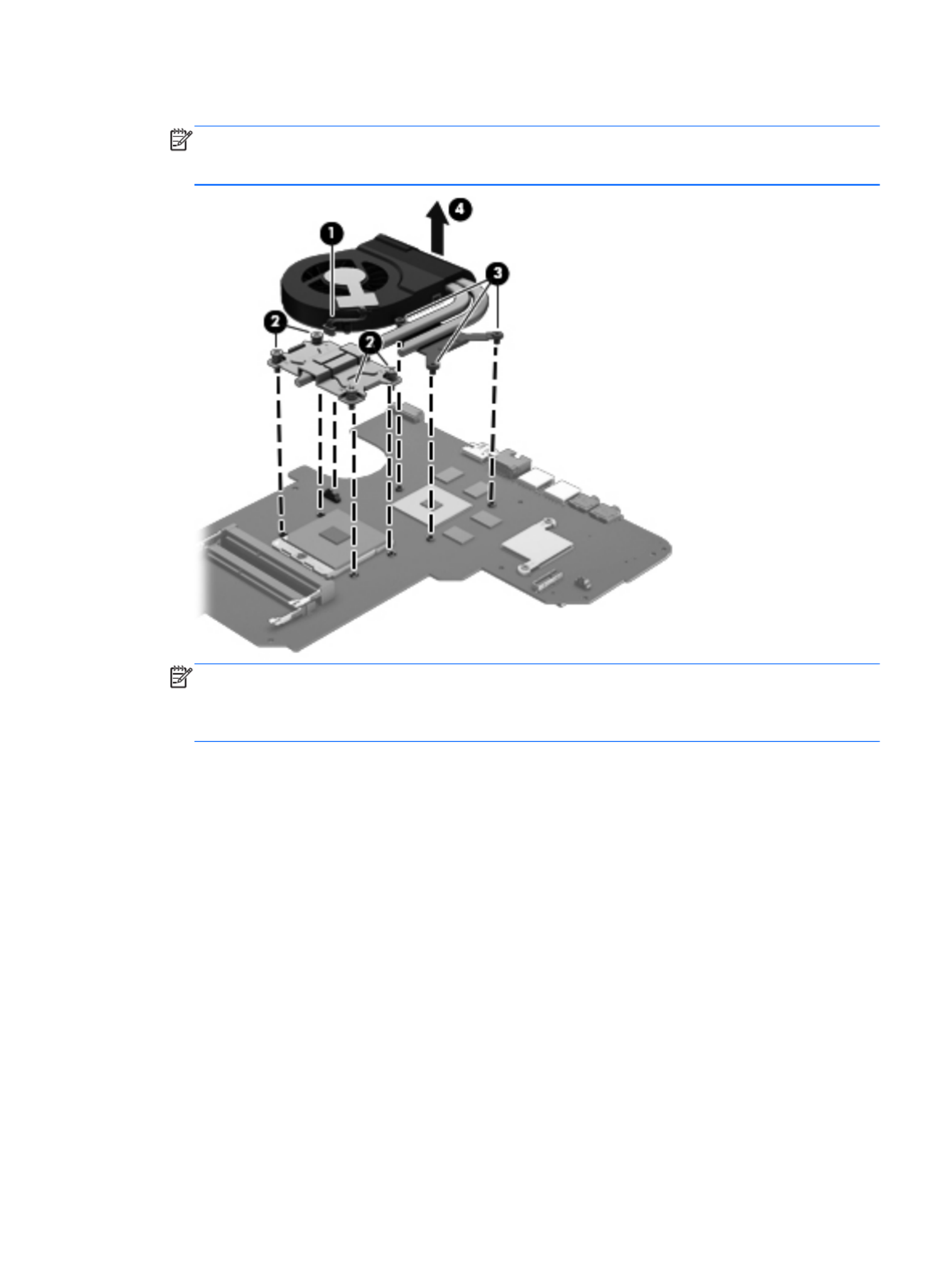
4. Remove the fan and heat sink (4).
NOTE: Due to the adhesive quality of the thermal material located between the heat sink and
system board components, it may be necessary to move the heat sink from side to side to
detach it.
NOTE: The thermal material must be thoroughly cleaned from the surfaces of the heat sink
and the system board components each time the heat sink is removed. Replacement
thermal material is included with the base enclosure, heat sink, processor, and system board
spare part kits.
●Thermal paste is used on the processor (1) and the heat sink section (2) that services it
●A thermal pad is used on the graphics subsystem chip (3) and the heat sink section (4) that
services it (only on computer models equipped with a graphics subsystem with
discrete memory)
Component replacement procedures 69

1. If it is necessary to replace the fan, turn the fan and heat sink upside down with the fan
toward you.
2. Remove the two PM 1.5 × 2.5 screws (1) that secure the fan to the heat sink and remove the two
clips that secure the fan to the heat sink.
3. Remove the heat sink (2) from the fan.
Reverse this procedure to reassemble and install the fan and heat sink.
70 Chapter 4 Removal and replacement procedures

PCH heat sink
Description Spare part number
PCH heat sink 683843-001
Before removing the PCH heat sink, follow these steps:
1. Shut down the computer. If you are unsure whether the computer is off or in Hibernation, turn
the computer on, and then shut it down through the operating system.
2. Disconnect all external devices connected to the computer.
3. Disconnect the power from the computer by first unplugging the power cord from the AC outlet
and then unplugging the AC adapter from the computer.
4. Remove the battery (see Battery on page 32).
5. Remove the service door (see Service door on page 33).
6. Remove the optical drive (see Optical drive on page 34).
7. Remove the hard drive (see {Xref Error! Target does not exist.})
8. Remove the keyboard (see Keyboard on page 43).
9. Remove the top cover (see Top cover on page 47).
10. Remove the system board (see System board on page 64).
Remove the PCH heat sink:
1. Remove the two PM 2.0 x 3.0 screws (1) that secure the PCH heat sink to the system board.
Component replacement procedures 71

2. Remove the PCH heat sink by lifting straight up (2).
NOTE: Due to the adhesive quality of the thermal material located between the heat sink and
system board components, it may be necessary to move the heat sink from side to side to
detach it.
NOTE: The thermal material must be thoroughly cleaned from the surfaces of the heat sink
and the system board components each time the heat sink is removed. Replacement
thermal material is included with the base enclosure, heat sink, processor, and system board
spare part kits.
Reverse this procedure to install the PCH heat sink.
Processor
NOTE: The processor spare part kit includes replacement thermal material.
Description Spare part number
AMD A10-4600M processor (3.2 GHz/2.3 GHz, 1600 MHz/4.0 MB L2 cache, DDR3, quad core,
35W)
683046-001
AMD A8-4500M processor (2.8 GHz/1.9 GHz, 1600 MHz/4.0 MB L2 cache, DDR3, quad core,
35W)
683048-001
AMD A6-4400M processor (3.2 GHz/2.7 GHz, 1600 MHz/1.0 MB L2 cache, DDR3, dual core, 35W) 683047-001
Before removing the processor, follow these steps:
1. Shut down the computer. If you are unsure whether the computer is off or in Hibernation, turn
the computer on, and then shut it down through the operating system.
2. Disconnect all external devices connected to the computer.
3. Disconnect the power from the computer by first unplugging the power cord from the AC outlet
and then unplugging the AC adapter from the computer.
4. Remove the battery (see Battery on page 32).
72 Chapter 4 Removal and replacement procedures

5. Remove the service door (see Service door on page 33).
6. Remove the optical drive (see Optical drive on page 34).
7. Remove the hard drive (see {Xref Error! Target does not exist.})
8. Remove the keyboard (see Keyboard on page 43).
9. Remove the top cover (see Top cover on page 47).
10. Remove the system board (see System board on page 64).
11. Remove the heat sink (see Fan and heat sink on page 68).
Remove the processor:
1. Use a flat-bladed screw driver (1) to turn the processor locking screw one-half turn
counterclockwise, until you hear a click.
2. Lift the processor (2) straight up, and remove it.
NOTE: The gold triangle on the processor (3) must be aligned with the triangle icon embossed
on the processor socket when you install the processor.
Reverse this procedure to install the processor.
Optical drive cable
Description Spare part number
Optical drive cable 682742-001
Before removing the optical drive cable, follow these steps:
1. Shut down the computer. If you are unsure whether the computer is off or in Hibernation, turn
the computer on, and then shut it down through the operating system.
2. Disconnect all external devices connected to the computer.
3. Disconnect the power from the computer by first unplugging the power cord from the AC outlet
and then unplugging the AC adapter from the computer.
4. Remove the battery (see Battery on page 32).
5. Remove the service door (see Service door on page 33).
Component replacement procedures 73
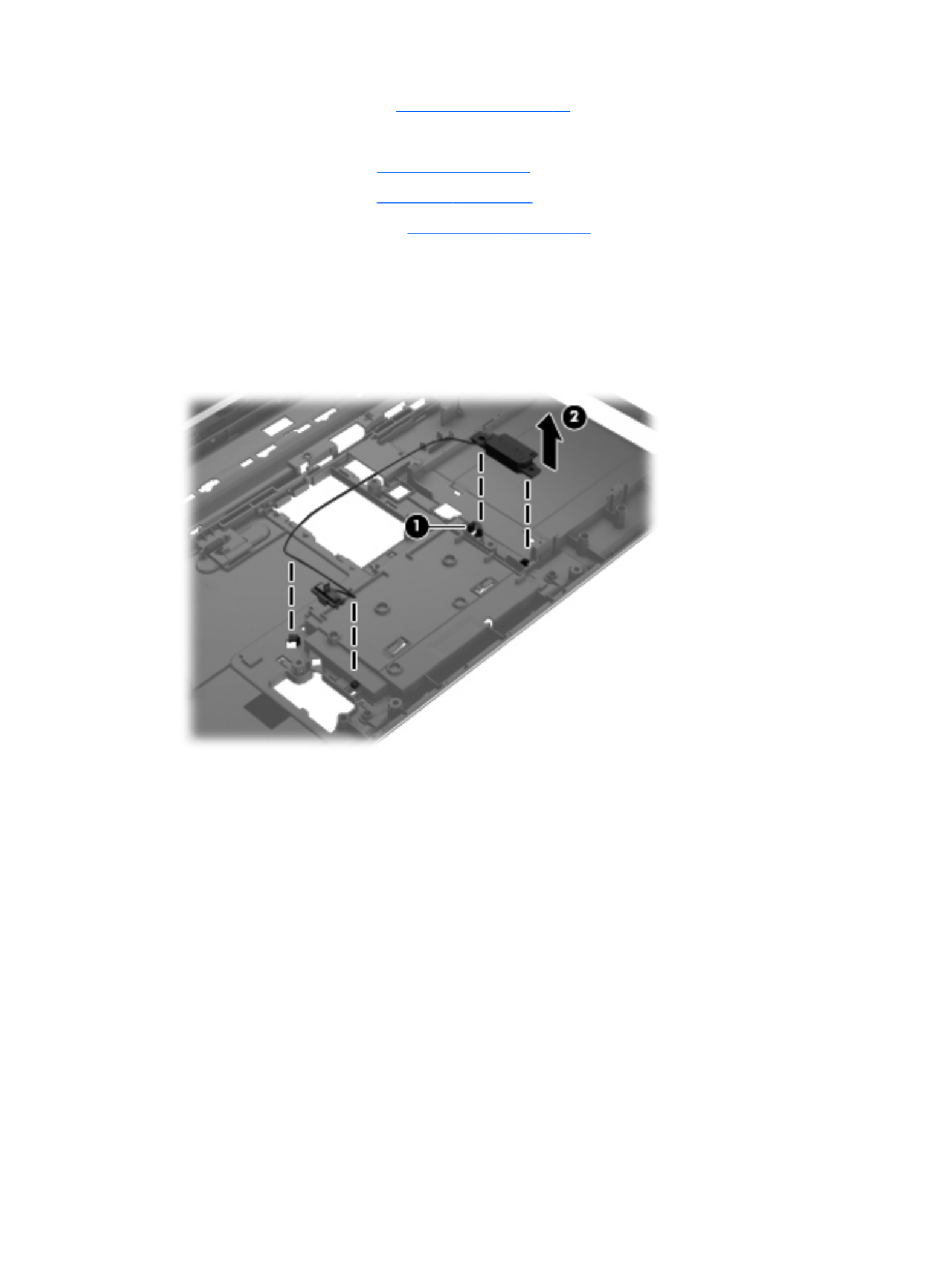
6. Remove the optical drive (see Optical drive on page 34).
7. Remove the hard drive (see {Xref Error! Target does not exist.})
8. Remove the keyboard (see Keyboard on page 43).
9. Remove the top cover (see Top cover on page 47).
10. Remove the system board (see System board on page 64).
Remove the optical drive cable:
1. Release the optical drive cable from the clips built into the base enclosure.
2. Release the optical drive connector from the base enclosure by prying the clips (1) that secure
the optical drive connector to the base enclosure.
3. Remove the optical drive cable from the base enclosure (2).
Reverse this procedure to install the optical drive cable.
74 Chapter 4 Removal and replacement procedures

5 Using Setup Utility (BIOS) and System
Diagnostics
Setup Utility, or Basic Input/Output System (BIOS), controls communication between all the input and
output devices on the system (such as disk drives, display, keyboard, mouse, and printer). Setup
Utility (BIOS) includes settings for the types of devices installed, the startup sequence of the
computer, and the amount of system and extended memory.
Starting Setup Utility (BIOS)
To start Setup Utility (BIOS), follow these steps:
1. Turn on or restart the computer, and then press esc while the “Press the ESC key for Startup
Menu” message is displayed at the bottom of the screen.
2. Press f10 to enter Setup Utility (BIOS).
Information on how to navigate in Setup Utility (BIOS) is located at the bottom of the screen.
NOTE: Use extreme care when making changes in Setup Utility (BIOS). Errors can prevent the
computer from operating properly.
Updating the BIOS
Updated versions of the BIOS may be available on the HP website.
Most BIOS updates on the HP website are packaged in compressed files called SoftPaqs.
Some download packages contain a file named Readme.txt, which contains information regarding
installing and troubleshooting the file.
Determining the BIOS version
To determine whether available BIOS updates contain later BIOS versions than those currently
installed on the computer, you need to know the version of the system BIOS currently installed.
BIOS version information (also known as ROM date and System BIOS) can be displayed by pressing
fn+esc (if you are already in Windows) or by using Setup Utility (BIOS).
1. Start Setup Utility (BIOS).
2. Use the arrow keys to select Main.
3. To exit Setup Utility (BIOS) without saving your changes, use the tab key and the arrow keys to
select Exit .> Exit Discarding Changes, and then press enter
Starting Setup Utility (BIOS) 75

Downloading a BIOS update
CAUTION: To reduce the risk of damage to the computer or an unsuccessful installation, download
and install a BIOS update only when the computer is connected to reliable external power using the
AC adapter. Do not download or install a BIOS update while the computer is running on battery
power, docked in an optional docking device, or connected to an optional power source. During the
download and installation, follow these instructions:
Do not disconnect power from the computer by unplugging the power cord from the AC outlet.
Do not shut down the computer or initiate Sleep or Hibernation.
Do not insert, remove, connect, or disconnect any device, cable, or cord.
1. Select Start .> Help and Support > Maintain
2. Follow the on-screen instructions to identify your computer and access the BIOS update you
want to download.
3. At the download area, follow these steps:
a. Identify the BIOS update that is later than the BIOS version currently installed on your
computer. Make a note of the date, name, or other identifier. You may need this information
to locate the update later, after it has been downloaded to your hard drive.
b. Follow the on-screen instructions to download your selection to the hard drive.
Make a note of the path to the location on your hard drive where the BIOS update is
downloaded. You will need to access this path when you are ready to install the update.
NOTE: If you connect your computer to a network, consult the network administrator before
installing any software updates, especially system BIOS updates.
BIOS installation procedures vary. Follow any instructions that are displayed on the screen after the
download is complete. If no instructions are displayed, follow these steps:
1. Open Windows Explorer by selecting Start > Computer.
2. Double-click your hard drive designation. The hard drive designation is typically Local Disk (C:).
3. Using the hard drive path you recorded earlier, open the folder on your hard drive that contains
the update.
4. Double-click the file that has an .exe extension (for example, filename.exe).
The BIOS installation begins.
5. Complete the installation by following the on-screen instructions.
NOTE: After a message on the screen reports a successful installation, you can delete the
downloaded file from your hard drive.
Using System Diagnostics
System Diagnostics allows you to run diagnostic tests to determine if the computer hardware is
functioning properly.
76 Chapter 5 Using Setup Utility (BIOS) and System Diagnostics

To start System Diagnostics:
1. Turn on or restart the computer. While the “Press the ESC key for Startup Menu” message is
displayed in the lower-left corner of the screen, press esc. When the Startup Menu is displayed,
press f2.
2. Click the diagnostic test you want to run, and then follow the on-screen instructions.
NOTE: If you need to stop a diagnostics test while it is running, press esc.
Using System Diagnostics 77

6 Specifications
Computer specifications
Dimensions
Depth 24.5 cm (9.6 in)
Width 37.4 cm (14.7 in)
Height (front to rear) (1.2 to 1.4 in)3.1 to 3.6 cm
Weight (lowest weight configuration) < 2.5 kg (5.5 lbs)
Input power
Operating voltage 18.5 V dc @ 3.5 A or 19.5 V dc @ 3.33 A – 65 W
19 V dc @ 4.74 A or 19.5 V dc @ 4.62 A – 90 W
Operating current 3.5 A
Temperature
Operating 5°C to 35°C (41°F to 95°F)
Nonoperating -20°C to 60°C (-4°F to 140°F)
Relative humidity
Operating 10% to 90%
Nonoperating 5% to 95%
Maximum altitude (unpressurized)
Operating -15 m to 3,048 m (-50 ft to 10,000 ft)
Nonoperating -15 m to 12,192 m (-50 ft to 40,000 ft)
Shock
Operating 125 g, 2 ms, half-sine
Nonoperating 200 g, 2 ms, half-sine
Random vibration
Operating 0.75 g zero-to-peak, 10 Hz to 500 Hz, 0.25 oct/
min sweep rate
Nonoperating 1.50 g zero-to-peak, 10 Hz to 500 Hz, 0.5 oct/min
sweep rate
NOTE: Applicable product safety standards specify thermal limits for plastic surfaces. The computer operates well within
this range of temperatures.
78 Chapter 6 Specifications

39.6-cm (15.6-in) display specifications
Dimensions
Height 21.0 cm (8.27 in)
Width 35.9 cm (14.1 in)
Diagonal 39.6 cm (15.6)
Number of colors Up to 16.8 million
Contrast ratio 300:1 (typical)
Brightness 200 cd/m² (nits) (typical)
Backlight LED
Total power consumption 4.1 W
Viewing angle ±45° horizontal, +15° up/-35° down (typical)
39.6-cm (15.6-in) display specifications 79

Hard drive specifications
1 TB* 750 GB* 640 GB* 500 GB* 320 GB*
Dimensions
Height 9.5 mm 9.5 mm 9.5 mm 9.5 mm 9.5 mm and 7.0
mm
Width 70 mm 70 mm 70 mm 70 mm 70 mm
Weight 107 g max 107 g max 107 g max 107 g max 107 g max
Interface type SATA SATA SATA SATA SATA
Transfer rate 300 MB/sec 300 MB/sec 300 MB/sec 300 MB/sec 300 MB/sec
Security ATA security ATA security ATA security ATA security ATA security
Seek times (typical read, including setting)
Single track 1.5 ms 1.0 ms 1.0 ms 1.5 ms 2.0 ms
Average 11.0 ms 14.0 ms 14.0 ms 12.0 ms 12.0 ms
Maximum 22.0 ms 24.0 ms 22.0 ms 22.0 ms 22.0 ms
Logical blocks 1,953,525,168 1,465,128,359 1,250,242,867 976,752,240 625,121,433
Disc rotational speed 5400 rpm 5400 and 7200
rpm
5400 rpm 5400 and 7200
rpm
5400 and 7200
rpm
Operating temperature 5°C to 55°C (41°F to 131°F)
*Hard drive storage capacity
When referring to hard drive storage capacity:
●1 TB = 1 trillion bytes
●1 GB = 1 billion bytes
Actual accessible capacity is less. Actual drive specifications may differ slightly.
NOTE: Certain restrictions and exclusions apply. Contact technical support for details.
80 Chapter 6 Specifications

DVD±RW and CD-RW SuperMulti Double-Layer Combo
Drive specifications
Applicable disc
Read CD-DA, CD+(E)G, CD-MIDI, CD-TEXT, CD-ROM, CD-ROM XA, MIXED
MODE CD, CD-I, CD-I Bridge (Photo-CD, Video CD), Multisession CD
(Photo-CD, CD-EXTRA, Portfolio, CD-R, CD-RW), CD-R, CD-RW, DVD-
ROM (DVD-5, DVD-9, DVD-10, DVD-18), DVD-R, DVD-RW, DVD+R, DVD
+RW, DVD-RAM
Write CD-R and CD-RW, DVD+R, DVD+RW, DVD-R, DVD-RW, DVD-RAM
Random access time
DVD < 230 ms
CD < 175 ms
Cache buffer 2 MB
Data transfer rate
24X CD-ROM 3,600 KB/sec
8X DVD-ROM 10,800 KB/sec
24X CD-R 3,600 KB/sec
16X CD-RW 2,400 KB/sec
8X DVD+R 10,800 KB/sec
4X DVD+RW 5,400 KB/sec
8X DVD-R 10,800 KB/sec
4X DVD-RW 5,400 KB/sec
2.4X DVD+R(9) 2,700 KB/sec
5X DVD-RAM 6,750 KB/sec
Transfer mode Multiword DMA Mode
DVD±RW and CD-RW SuperMulti Double-Layer Combo Drive specifications 81

Blu-ray Disc ROM and DVD±R/RW SuperMulti Double-
Layer Drive specifications
Applicable disc
Read BD-ROM, BD-ROM-DL, BD-R, BD-R-DL, BD-RE, BD-RE-DL, DVD-ROM,
DVD+R, DVD+R-DL, DVD+RW, DVD-R, DVD-R-DL, DVD-RW, DVD-RAM
(Ver.2), CD-DA, CD-ROM (mode 1 and mode 2), CD-ROM XA (mode 2,
form 1 and form 2), Photo CD (single and multiple sessions), CD Extra,
CD-R, CD-RW, and CD-TEXT
Write DVD-RAM (Ver.2), DVD+R, DVD-R, CD-R, and CD-ROM
Random access time
BD < 230 ms
DVD < 180 ms
CD < 180 ms
Cache buffer 4.5 MB
Data transfer rate
24X CD-ROM 3,600 KB/sec
8X DVD-ROM 10,800 KB/sec
4X BD 18,000 KB/sec
24X CD-R 3,600 KB/sec
16X CD-RW 2,400 KB/sec
8X DVD+R 10,800 KB/sec
4X DVD+RW 5,400 KB/sec
8X DVD-R 10,800 KB/sec
4X DVD-RW 5,400 KB/sec
2.4X DVD+R(9) 2,700 KB/sec
5X DVD-RAM 6,750 KB/sec
1X BD-ROM 4,500 KB/sec
1X BD-R read 4,500 KB/sec
1X BD-RE read 4,500 KB/sec
Transfer mode Multiword DMA Mode
82 Chapter 6 Specifications

Creating the recovery media
1. Select Start and type recovery in the search field. Select Recovery Manager from the list.
Allow the action to continue, if prompted.
2. Click Recovery Media Creation.
3. Follow the on-screen instructions to continue.
To recover, see Recovering the original system using HP Recovery Manager on page 86
Creating system restore points
A system restore point is a snapshot of certain hard drive contents saved by Windows System
Restore at a specific time. A restore point contains information such as registry settings that Windows
uses. Restoring to a previous restore point allows you to reverse changes that have been made to the
system since the restore point was created.
Restoring to an earlier system restore point does not affect data files saved or emails created since
the last restore point, but it does affect software you may have installed.
For example, if you download a photo from a digital camera and then restore the computer to the
state it was on the previous day, the photo remains on the computer.
However, if you install photo viewing software and then restore your computer to the state it was on
the previous day, the software will be uninstalled, and you won't be able to use it.
What you need to know
●If you restore to a restore point and then change your mind, you can undo the restoration.
●You should create system restore points:
◦Before you add or change software or hardware
◦Periodically, whenever the computer is running normally
●System Restore also saves shadow copies of files that have been changed since the last restore
point was created. For more information about using shadow copies to restore, see Help and
Support.
Creating a system restore point
1. Select Start > Control Panel > System and Security .> System
2. In the left pane, click System Protection.
3. Click the System Protection tab.
4. Click Create, and follow the on-screen instructions.
To restore, see Restoring to a previous system restore point on page 86.
Backing up system and personal information
Your computer stores information that is important to you, such as files, emails, and photos, and you
will want to keep that information even if you download a virus or the system stops working properly.
How completely you are able to recover your files depends on how recent your backup is. As you add
new software and data files, you should create backups on a regular basis.
84 Chapter 7 Backing up, restoring, and recovering

Tips for a successful backup
●Number backup discs before inserting them into the optical drive.
●Store personal files in the Documents, Music, Pictures, and Videos libraries, and back up these
folders periodically.
●Save customized settings in a window, toolbar, or menu bar by taking a screen shot of your
settings. The screen shot can be a time-saver if you have to re-enter your preferences.
To create a screen shot:
1. Display the screen you want to save.
2. Copy the screen image:
To copy only the active window, press alt+prt sc.
To copy the entire screen, press prt sc.
3. Open a word-processing document or graphics editing program, and then select Edit > Paste.
The screen image is added to the document.
4. Save and print the document.
What you need to know
●You can back up your information to an optional external hard drive, a flash drive, a network
drive, or discs.
●Connect the computer to AC power during backups.
●Allow enough time for the backup. Depending on files sizes, it may take more than an hour.
●Verify the amount of free space on your backup storage device before you back up.
●You should back up:
◦Before adding or changing software or hardware.
◦Before the computer is repaired or restored.
◦On a regular schedule to be sure you have recent copies of personal information.
◦After you add many files—for example, if you saved videos from a birthday party.
◦Before using antivirus software to remove a malicious program.
◦After adding information that is hard to replace, such as pictures, videos, music, project
files, or data records.
Creating a backup using Windows Backup and Restore
Windows allows you to back up files using Windows Backup and Restore. You can select the level
you want to back up, from individual folders to drives. The backups are compressed to save space.
To back up:
1. Select Start > Control Panel > System and Security > Backup and Restore.
2. Follow the on-screen instructions to schedule and create a backup.
NOTE: Windows includes the User Account Control feature to improve the security of the computer.
You may be prompted for your permission or password for tasks such as installing software, running
utilities, or changing Windows settings. See Help and Support for more information.
Creating backups 85

To restore, see Restoring specific files using Windows Backup and Restore on page 86.
Restore and recovery
Restoring to a previous system restore point
Sometimes installing a software program causes your computer or Windows to behave unpredictably.
Usually uninstalling the software fixes the problems. If uninstalling does not fix the problems, you can
restore the computer to a previous system restore point (created at an earlier date and time).
To restore to a previous system restore point, when the computer was running correctly:
1. Select Start > Control Panel > System and Security .> System
2. In the left pane, click System Protection.
3. Click the System Protection tab.
4. Click System Restore, and follow the on-screen instructions.
Restoring specific files
If files are accidentally deleted from the hard disk and they can no longer be restored from the
Recycle Bin, or if files become corrupt, restoring specific files is useful. Restoring specific files is also
useful if you ever choose to recover the original system using HP Recovery Manager. You can only
restore specific files that you have backed up before.
Restoring specific files using Windows Backup and Restore
Windows allows you to restore files that were backed up using Windows Backup and Restore:
1. Select Start > Control Panel > System and Security > Backup and Restore.
2. Follow the on-screen instructions to restore your backup.
NOTE: Windows includes the User Account Control feature to improve the security of the computer.
You may be prompted for your permission or password for tasks such as installing software, running
utilities, or changing Windows settings. See Help and Support for more information.
Recovering the original system using HP Recovery Manager
HP Recovery Manager software allows you to repair or recover the computer to its original factory
state.
What you need to know
●HP Recovery Manager recovers only software that was installed at the factory. For software not
provided with this computer, you must either download the software from the manufacturer's
website or reinstall the software from the disc provided by the manufacturer.
●A system recovery should be used as a final attempt to correct computer issues. If you have not
already tried restore points (see Restoring to a previous system restore point on page 86) and
partial restores (see Restoring specific files on page 86), try them before using HP Recovery
Manager to recover your system.
●A system recovery must be performed if the computer hard drive fails or if all attempts to correct
any functional computer issues fail.
86 Chapter 7 Backing up, restoring, and recovering

●If the recovery media do not work, you can obtain recovery discs for your system from the HP
website.
●The Minimized Image Recovery option is recommended for advanced users only. All hardware-
related drivers and software are re-installed, but other software applications are not. Do not
interrupt the process until it is complete, otherwise the recovery will fail.
Recovering using HP Recovery partition (select models only)
The HP Recovery partition (select models only), allows you to restore your system without the need
for recovery discs or a recovery flash drive. This type of recovery can only be used if the hard drive is
still working.
To check for the presence of a recovery partition, select Start, right-click Computer then select
Manage > Disk Management. If the recovery partition is present, a Recovery drive is listed in the
window.
NOTE: Recovery discs have been included if your computer did not ship with a recovery partition.
1. Access HP Recovery Manager in either of the following ways:
●Select Start and type recovery in the search field. Select Recovery Manager from the
list.
– or –
●Turn on or restart the computer, and then press esc while the “Press the ESC key for
Startup Menu” message is displayed at the bottom of the screen. Then press f11 while the
“F11 (System Recovery)” message is displayed on the screen.
2. Click System Recovery in the HP Recovery Manager window.
3. Follow the on-screen instructions.
Recovering using the recovery media
1. If possible, back up all personal files.
2. Insert the first recovery disc into the optical drive on your computer or an optional external
optical drive, and then restart the computer.
– or –
Insert the recovery flash drive into a USB port on your computer, and then restart the computer.
NOTE: If the computer does not automatically restart in HP Recovery Manager, change the
computer boot order. See Changing the computer boot order on page 87.
3. Press f9 at system bootup.
4. Select the optical drive or the flash drive.
5. Follow the on-screen instructions.
Changing the computer boot order
To change the boot order for recovery discs:
1. Restart the computer.
2. Press esc while the computer is restarting, and then press f9 for boot options.
3. Select Internal CD/DVD ROM Drive from the boot options window.
Restore and recovery 87

8 Power cord set requirements
The wide-range input feature of the computer permits it to operate from any line voltage from 100 to
120 V ac, or from 220 to 240 V ac.
The 3-conductor power cord set included with the computer meets the requirements for use in the
country or region where the equipment is purchased.
Power cord sets for use in other countries or regions must meet the requirements of the country and
region where the computer is used.
Requirements for all countries
The following requirements are applicable to all countries and regions:
●The length of the power cord set must be at least 1.5 m (5.0 ft) and no more than 2.0 m (6.5 ft).
●All power cord sets must be approved by an acceptable accredited agency responsible for
evaluation in the country or region where the power cord set will be used.
●The power cord sets must have a minimum current capacity of 10 A and a nominal voltage rating
of 125 or 250 V ac, as required by the power system of each country or region.
●The appliance coupler must meet the mechanical configuration of an EN 60 320/IEC 320
Standard Sheet C13 connector for mating with the appliance inlet on the back of the computer.
Requirements for all countries 89

9 Recycling
When a battery has reached the end of its useful life, do not dispose of the battery in general
household waste. Follow the local laws and regulations in your area for battery disposal. HP
encourages customers to recycle used electronic hardware, HP original print cartridges, and
rechargeable batteries.
For more information about recycling programs, see the HP website at www.hp.com/recycle.
92 Chapter 9 Recycling

Index
A
AC adapter
light 11
spare part numbers 20
action keys, identifying 7
antenna
locations 5
removal 62
spare part number 18, 56
audio, product description 2
audio-in (microphone) jack
identifying 10
audio-out (headphone) jack
identifying 10
B
backups 83
base enclosure, spare part
number 16
battery
removal 32
spare part numbers 16, 32
battery bay 12
battery release latch 12
bezel
spare part number 18
BIOS
determining version 75
downloading an update 76
updating 75
Blu-ray Disc ROM and DVD±R/RW
SuperMulti Double-Layer Drive
specifications 82
Blu-ray ROM DVD±R/RW Super
Multi Double-Layer Drive
precautions 26
removal 19, 34
spare part numbers 19, 34
boot order
changing 87
bottom components 12
buttons
left TouchPad 9
optical drive eject 11
power 6
right TouchPad 9
TouchPad on/off 9
buttons component 6
C
cables, service considerations 25
camera, product description 2
caps lock light, identifying 8
chipset, product description 1
components
bottom 12
button 6
display 5
keys 7
left side 10
lights 8
right side 11
speakers 6
TouchPad 9
computer feet
locations 30
spare part number 30
computer specifications 78
connector, power 11
connectors, service
considerations 25
D
deleted files
restoring 86
Digital media slot, identifying 10
display assembly
removal 56
spare part number 15
spare part numbers 56
Display back cover 56
display back cover, spare part
number 18
display bezel
illustrated 18
removal 58
spare part number 18, 56
Display Cable Kit, spare part
number 56
display cable, spare part number
18
display components 5
display enclosure, illustrated 18
Display hinge cover, spare part
number 18
Display Hinge Kit, spare part
number 56
display panel
illustrated 18
product description 1
removal 59
spare part number 18, 56
display panel cable
removal 61
spare part number 56
display specifications 79
display subcomponents
illustrated 18
spare part numbers 18
drives, preventing damage 26
DVD±RW and CD-RW Super Multi
Double-Layer Combo Drive
precautions 26
removal 19, 34
spare part numbers 19, 34
DVD±RW and CD-RW SuperMulti
Double-Layer Combo Drive
specifications 81
E
electrostatic discharge 26
equipment guidelines 29
esc key, identifying 7
Ethernet, product description 2
external media cards, product
description 3
external monitor port 10
F
fan
removal 68
spare part number 68
Index 93

power requirements, product
description 3
processor
product description 1
removal 72
spare part numbers 16, 72
product description
audio 2
camera 2
chipset 1
display panel 1
Ethernet 2
external media cards 3
graphics 1
hard drives 2
keyboard 3
memory module 2
operating system 4
optical drive 2
pointing devices 3
ports 3
power requirements 3
processors 1
product name 1
security 4
serviceability 4
wireless 3
product name 1
R
recovering from the recovery
discs 87
recovering the original system 86
recovery 86
HP Recovery Manager 86
recovery discs 83
recovery media 83
recovery, system 86
removal/replacement
preliminaries 25
procedures 29
restore points 84
restoring the original system
creating recovery media 83
right-side components 11
RJ-45 (network) jack, identifying
10
RTC battery
removal 67
spare part number 16, 67
Rubber Feet Kit, spare part
number 30
S
security cable slot, identifying 11
security, product description 4
serial number 13
service considerations
cables 25
connectors 25
plastic parts 25
service door
removal 33
service door release latch 12
service door, identifying 12
service label 30
serviceability, product
description 4
slots
Digital media 10
security cable 11
speaker assembly
spare part number 16
Speaker Kit, spare part number
50
speakers
identifying 6
removal 50
spare part number 50
specifications
Blu-ray Disc ROM and DVD±R/
RW SuperMulti Double-Layer
Drive 82
computer 78
display 79
DVD±RW and CD-RW
SuperMulti Double-Layer
Combo Drive 81
hard drive 80
optical drive 81, 82
supported discs 83
system board
removal 64
spare part numbers 16, 64
system recovery 86
system restore points 84
creating 84
T
tools required 25
top cover
removal 47
spare part number 15
spare part numbers 47
TouchPad
buttons 9
TouchPad button board
removal 53
spare part number 53
TouchPad components 9
TouchPad LED board
removal 54
spare part number 54
TouchPad light 9
TouchPad on/off button 9
TouchPad reader light 8
TouchPad zone, identifying 9
transporting guidelines 28
U
USB 2.0 ports, identifying 11
USB 3.0 ports, identifying 10
USB board
removal 62
spare part number 16
V
vents, identifying 10, 12
W
webcam light 5
webcam module, spare part
number 18
webcam, location 5
webcam/microphone module
removal 58
spare part number 56
Windows applications key,
identifying 7
Windows Backup and Restore
restoring files 86
Windows logo key, identifying 7
wireless antenna
locations 5
removal 62
spare part number 18, 56
wireless light 8
wireless, product description 3
WLAN module
removal 41
spare part numbers 17, 41
Index 95

workstation guidelines 28
96 Index
Product specificaties
| Merk: | HP |
| Categorie: | Laptop |
| Model: | g6-2269sa |
| Kleur van het product: | Black, Blue |
| Gewicht: | 2480 g |
| Breedte: | 376 mm |
| Diepte: | 244 mm |
| Hoogte: | 36.3 mm |
| Gebruikershandleiding: | Ja |
| AC-adapterfrequentie: | 50 - 60 Hz |
| AC-adapter ingangsspanning: | 100 - 240 V |
| Bluetooth: | Nee |
| Beeldschermdiagonaal: | 15.6 " |
| Resolutie: | 1366 x 768 Pixels |
| Touchscreen: | Nee |
| Oorspronkelijke beeldverhouding: | 16:9 |
| Frequentie van processor: | 2.5 GHz |
| Processorfamilie: | Intel® Core™ i5 |
| Processormodel: | i5-3210M |
| Aantal processorkernen: | 2 |
| Wi-Fi-standaarden: | 802.11b, 802.11g, Wi-Fi 4 (802.11n) |
| Vormfactor: | Clamshell |
| Inclusief besturingssysteem: | Windows 8 |
| Type aansluitplug: | 3,5 mm |
| Ethernet LAN: | Ja |
| Meegeleverde kabels: | AC |
| Geïntegreerde geheugenkaartlezer: | Ja |
| Typische contrastverhouding: | 300:1 |
| Helderheid: | 200 cd/m² |
| Processor lithografie: | 22 nm |
| Snelstartgids: | Ja |
| Inclusief AC-adapter: | Ja |
| Land van herkomst: | China |
| LED backlight: | Ja |
| Aantal USB 2.0-poorten: | 1 |
| VGA (D-Sub)poort(en): | 1 |
| Aantal HDMI-poorten: | 1 |
| Microfoon, line-in ingang: | Ja |
| DVI-poort: | Nee |
| Aantal Ethernet LAN (RJ-45)-poorten: | 1 |
| Bevestigingsmogelijkheid voor kabelslot: | Ja |
| Ingebouwde luidsprekers: | Ja |
| Aantal ingebouwde luidsprekers: | 2 |
| Hoofdtelefoonuitgangen: | 1 |
| Beeldscherm, aantal kleuren: | 16.78 miljoen kleuren |
| AC-adapter, vermogen: | 65 W |
| Ingebouwde microfoon: | Ja |
| Intern geheugen: | 6 GB |
| Opslagmedia: | HDD |
| Levensduur accu/batterij: | - uur |
| Intern geheugentype: | DDR3-SDRAM |
| Duurzaamheidscertificaten: | EPEAT Silver, ENERGY STAR |
| Ethernet LAN, data-overdrachtsnelheden: | 10, 100 Mbit/s |
| Bekabelingstechnologie: | 10/100Base-T(X) |
| Temperatuur bij opslag: | -20 - 60 °C |
| Intel® Wireless Display (Intel® WiDi): | Ja |
| Aantal poorten USB 3.2 Gen 1 (3.1 Gen 1) Type A: | 2 |
| Processor socket: | BGA 1023 |
| Stepping: | L1 |
| Systeembus: | 5 GT/s |
| Processor aantal threads: | 4 |
| PCI Express slots versie: | 3.0 |
| Processor operating modes: | 64-bit |
| Processor cache: | 3 MB |
| Tjunction: | 105 °C |
| Bus type: | DMI |
| PCI Express configuraties: | 1x16, 2x8, 1x8+2x4 |
| Thermal Design Power (TDP): | 35 W |
| Codenaam processor: | Ivy Bridge |
| Maximaal aantal PCI Express-lijnen: | 16 |
| Processor cache type: | L3 |
| ECC ondersteund door processor: | Nee |
| Processorfabrikant: | Intel |
| Architectuur besturingssysteem: | 64-bit |
| Maximum intern geheugen: | 8 GB |
| Totale opslagcapaciteit: | 1000 GB |
| Soort optische drive: | DVD Super Multi DL |
| Ingebouwde grafische adapter: | Ja |
| Aparte grafische adapter: | Nee |
| Familie ingebouwde grafische adapter: | Intel® HD Graphics |
| On-board graphics adapter model: | Intel® HD Graphics 4000 |
| Basisfrequentie ingebouwde grafische adapter: | 650 MHz |
| Graphics on-board -adapter dynamische frequentie (max): | 1100 MHz |
| On-board grafische adapter ID: | 0x166 |
| Numeriek toetsenblok: | Ja |
| Ondersteunde instructie sets: | AVX |
| Intel® My WiFi Technology (Intel® MWT): | Ja |
| Intel® Hyper Threading Technology (Intel® HT Technology): | Ja |
| Intel® Turbo Boost Technology: | 2.0 |
| Intel® Quick Sync Video Technology: | Ja |
| Intel® InTru™ 3D Technology: | Ja |
| Intel® Clear Video HD Technology (Intel® CVT HD): | Ja |
| Intel® Insider™: | Ja |
| Intel® Flex Memory Access: | Ja |
| Intel® AES New Instructions (Intel® AES-NI): | Ja |
| Enhanced Intel SpeedStep Technology: | Ja |
| Execute Disable Bit: | Ja |
| Idle States: | Ja |
| Thermal Monitoring Technologies: | Ja |
| CPU configuratie (max): | 1 |
| Intel® Enhanced Halt State: | Ja |
| Intel® Clear Video Technology for Mobile Internet Devices (Intel® CVT for MID): | Nee |
| Intel® VT-x with Extended Page Tables (EPT): | Ja |
| Ingebouwde opties beschikbaar: | Nee |
| Graphics & IMC lithografie: | 22 nm |
| Intel® Secure Key: | Ja |
| Intel® 64: | Ja |
| Intel® Virtualization Technology for Directed I/O (VT-d): | Ja |
| Intel® Clear Video-technologie: | Nee |
| Intel® Virtualization Technology (VT-x): | Ja |
| Verpakkingsgrootte processor: | 31.0 x 24.0 (BGA1023) mm |
| Conflictvrije processor: | Ja |
| Intel® Identity Protection Technology (Intel® IPT): | Ja |
| Versie Intel® Identity Protection Technology: | 1.00 |
| Versie Intel® Secure Key Technology: | 1.00 |
| ARK ID processor: | 65708 |
| Intel® Trusted Execution Technology: | Nee |
| Intel® Anti-Theft Technology (Intel® AT): | Ja |
| SmartCard-slot: | Nee |
| Luchtvochtigheid bij opslag: | 5 - 95 procent |
| Maximale turbofrequentie van processor: | 3.1 GHz |
| Processorcode: | SR0N0 |
| Discreet grafische adapter model: | Niet beschikbaar |
| Aanwijsapparaat: | Touchpad |
| Windows-toetsen: | Ja |
| Merk luidsprekers: | Altec Lansing |
| Geheugenlayout: | 1 x 2 + 1 x 4 GB |
| Geheugenslots: | 2x SO-DIMM |
| Full-size toetsenbord: | Ja |
| Eiland-stijl keyboard: | Ja |
| Chipset moederbord: | Intel HM76 Express |
| Hoogte, in bedrijf: | -15 - 3048 m |
| Hoogte bij opslag: | -15 - 12192 m |
| Het aantal geïnstalleerde HDD's: | 1 |
| HDD capaciteit: | 1000 GB |
| HDD interface: | SATA |
| HDD rotatiesnelheid: | 5400 RPM |
| CPU multiplier (bus/core ratio): | 25 |
| FSB Parity: | Nee |
| Front-side bus processor: | - MHz |
| Intel® Demand Based Switching: | Nee |
| Charging port type: | DC-in ingang |
| Meegeleverde drivers: | Ja |
| Type CardBus PCMCIA-slot: | Nee |
| Processorserie: | Intel Core i5-3200 Mobile series |
| ExpressCard slot: | Nee |
| S/PDIF-uitgang: | Nee |
| Intel® Dual Display Capable Technology: | Ja |
| Intel® FDI Technology: | Ja |
| Intel® Rapid Storage Technology: | Nee |
| Intel® Fast Memory Access: | Ja |
| L3 cache: | 3 MB |
| Intel® Smart Cache: | Ja |
| Power auto-sensing: | Ja |
| Maximaal intern geheugen (64-bit): | 8 GB |
| Geïnstalleerde processorcache: | 3 MB |
| Microfoonaansluiting: | 3,5 mm |
| Wifi: | Ja |
| Bedrijfstemperatuur (T-T): | 5 - 35 °C |
| Relatieve vochtigheid in bedrijf (V-V): | 10 - 90 procent |
| Type product: | Notebook |
| Batterijtechnologie: | Lithium-Ion (Li-Ion) |
| Aantal batterijcellen: | 6 |
| Afbeeldingentypetoewijzing: | <div><img src="https://ark.intel.com/inc/images/diagrams/diagram-18.gif" title="Block Diagram" /></div> |
| Geïntegreerde 4G WiMAX: | Ja |
| Processorgeneratie: | Derde generatie Intel® Core™ i5 |
Heb je hulp nodig?
Als je hulp nodig hebt met HP g6-2269sa stel dan hieronder een vraag en andere gebruikers zullen je antwoorden
Handleiding Laptop HP

4 Maart 2025
5 Februari 2025
27 December 2024
27 December 2024
27 December 2024
6 December 2024
24 November 2024
24 November 2024
24 November 2024
24 November 2024
Handleiding Laptop
- Laptop Sony
- Laptop Samsung
- Laptop Xiaomi
- Laptop Panasonic
- Laptop LG
- Laptop Huawei
- Laptop Asus
- Laptop Medion
- Laptop Toshiba
- Laptop Acer
- Laptop Airis
- Laptop Alienware
- Laptop Apple
- Laptop Dell
- Laptop Denver
- Laptop Emachines
- Laptop Ematic
- Laptop Evga
- Laptop Fellowes
- Laptop Fujitsu
- Laptop Gigabyte
- Laptop Goclever
- Laptop Haier
- Laptop Hannspree
- Laptop Hercules
- Laptop Honor
- Laptop Hyundai
- Laptop Ibm
- Laptop Kogan
- Laptop Lenovo
- Laptop Lexibook
- Laptop Micromax
- Laptop Microsoft
- Laptop Mpman
- Laptop MSI
- Laptop Nec
- Laptop Packard Bell
- Laptop Peaq
- Laptop Pyle
- Laptop Razer
- Laptop Ricatech
- Laptop Schneider
- Laptop Sylvania
- Laptop Targa
- Laptop Thomson
- Laptop Trekstor
- Laptop Viewsonic
- Laptop Vizio
- Laptop Zebra
- Laptop Jay-tech
- Laptop Odys
- Laptop Olidata
- Laptop Oregon Scientific
- Laptop Naxa
- Laptop Aplic
- Laptop ADATA
- Laptop Humanscale
- Laptop Hamilton Buhl
- Laptop Compaq
- Laptop SIIG
- Laptop Tripp Lite
- Laptop SPC
- Laptop Prixton
- Laptop Coby
- Laptop AORUS
- Laptop Hähnel
- Laptop XPG
- Laptop ECS
- Laptop Inovia
- Laptop Ergotron
- Laptop Atdec
- Laptop Getac
- Laptop Vulcan
- Laptop System76
- Laptop General Dynamics Itronix
- Laptop CTL
- Laptop Everex
- Laptop Dynabook
- Laptop TechBite
- Laptop Schenker
Nieuwste handleidingen voor Laptop

2 April 2025

28 Maart 2025

27 Maart 2025
26 Maart 2025
10 Februari 2025
10 Februari 2025
10 Februari 2025
5 Februari 2025
30 Januari 2025

27 Januari 2025