Hikvision DS-2TD4136T-9 Handleiding
Hikvision
Bewakingscamera
DS-2TD4136T-9
Lees hieronder de 📖 handleiding in het Nederlandse voor Hikvision DS-2TD4136T-9 (143 pagina's) in de categorie Bewakingscamera. Deze handleiding was nuttig voor 49 personen en werd door 2 gebruikers gemiddeld met 4.5 sterren beoordeeld
Pagina 1/143

Therm -spectrum Network al Bi
Speed dome
User Manual
UD05160B

User Manual of Thermal -spectrum Network Speed dome Bi
© Hikvision
i
User
User
User
UserUser M
M
M
M Manual
anual
anual
anualanual
COPYRIGHT © 2017 Hangzhou Hikvision Digital Technology Co., Ltd.
AL
AL
AL
ALALL RIGHTS RESERVED.
L RIGHTS RESERVED.
L RIGHTS RESERVED.
L RIGHTS RESERVED.L RIGHTS RESERVED.
Any and all information, including, among others, wordings, pictures, graphs are the properties
of Hangzhou Hikvision Digital Technology Co., Ltd. or its subsidiaries (hereinafter referred to be
“Hikvision”). This user manual (hereinafter referred to be “the Manual”) cannot be reproduced,
changed, translated, or distributed, partially or wholly, by any means, without the prior written
permission of Hikvision. Unless otherwise stipulated, Hikvision does not make any warranties,
guarantees or representations, express or implied, regarding to the Manual.
Ab
Ab
Ab
AbAbout
out
out
outout t
t
t
t thi
hi
hi
hihis
s
s
s s Manu
Manu
Manu
ManuManual
al
al
alal
This Manual is applicable to Thermal -spectrum Network Speed domeBi .
The Manual includes instructions for using and managing the product. Pictures, charts, images
and all other information hereinafter are for description and explanation only. The information
contained in the Manual is subject to change, without notice, due to firmware updates or other
reasons. Please find the latest version in the company website
( ). http://overseas.hikvision.com/en/
Please use this user manual under the guidance of professionals.
T
T
T
TTrademark
rademark
rademark
rademarkrademarks Ac
s Ac
s Ac
s Acs Ack
k
k
kknowl
nowl
nowl
nowlnowled
ed
ed
ededgemen
gemen
gemen
gemengement
t
t
tt
and other Hikvision’s trademarks and logos are the properties of Hikvision in
various jurisdictions. Other trademarks and logos mentioned below are the properties of their
respective owners.
Legal
Legal
Legal
LegalLegal
Di
Di
Di
DiDiscl
scl
scl
sclsclai
ai
ai
aiaim
m
m
mmer
er
er
erer
TO THE MAXIMUM EXTENT PERMITTED BY APPLICABLE LAW, THE PRODUCT DESCRIBED,
WITH ITS HARDWARE, SOFTWARE AND FIRMWARE, IS PROVIDED “AS IS”, WITH ALL FAULTS
AND ERRORS, AND HIKVISION MAKES NO WARRANTIES, EXPRESS OR IMPLIED, INCLUDING
WITHOUT LIMITATION, MERCHANTABILITY, SATISFACTORY QUALITY, FITNESS FOR A
PARTICULAR PURPOSE, AND NON-INFRINGEMENT OF THIRD PARTY. IN NO EVENT WILL
HIKVISION, ITS DIRECTORS, OFFICERS, EMPLOYEES, OR AGENTS BE LIABLE TO YOU FOR
ANY SPECIAL, CONSEQUENTIAL, INCIDENTAL, OR INDIRECT DAMAGES, INCLUDING, AMONG
OTHERS, DAMAGES FOR LOSS OF BUSINESS PROFITS, BUSINESS INTERRUPTION, OR LOSS
OF DATA OR DOCUMENTATION, IN CONNECTION WITH THE USE OF THIS PRODUCT, EVEN IF
HIKVISION HAS BEEN ADVISED OF THE POSSIBILITY OF SUCH DAMAGES.
REGARDING TO THE PRODUCT WITH INTERNET ACCESS, THE USE OF PRODUCT SHALL BE
WHOLLY AT YOUR OWN RISKS. HIKVISION SHALL NOT TAKE ANY RESPONSIBILITES FOR
ABNORMAL OPERATION, PRIVACY LEAKAGE OR OTHER DAMAGES RESULTING FROM CYBER
ATTACK, HACKER ATTACK, VIRUS INSPECTION, OR OTHER INTERNET SECURITY RISKS;
HOWEVER, HIKVISION WILL PROVIDE TIMELY TECHNICAL SUPPORT IF REQUIRED.
SURVEILLANCE LAWS VARY BY JURISDICTION. PLEASE CHECK ALL RELEVANT LAWS IN
YOUR JURISDICTION BEFORE USING THIS PRODUCT IN ORDER TO ENSURE THAT YOUR USE

User Manual of Thermal Network Speed dome
© Hikvision
ii
CONFORMS THE APPLICABLE LAW. HIKVISION SHALL NOT BE LIABLE IN THE EVENT THAT
THIS PRODUCT IS USED WITH ILLEGITIMATE PURPOSES.
IN THE EVENT OF ANY CONFLICTS BETWEEN THIS MANUAL AND THE APPLICABLE LAW,
THE LATER PREVAILS.

User Manual of Thermal Network Speed dome
© Hikvision
iii
Regul
Regul
Regul
RegulRegulat
at
at
atator
or
or
orory
y
y
y y In
In
In
InInfor
for
for
forform
m
m
mmat
at
at
atati
i
i
iio
o
o
oon
n
n
nn
FCC Informati
FCC Informati
FCC Informati
FCC InformatiFCC Information
on
on
onon
Please take attention that changes or modification not expressly approved by the party
responsible for compliance could void the user’s authority to operate the equipment.
FCC com
FCC com
FCC com
FCC comFCC compl
pl
pl
plpli
i
i
iiance:
ance:
ance:
ance:ance:
This equipment has been tested and found to comply with the limits for
a Class A digital device, pursuant to part 15 of the FCC Rules. These limits are designed to
provide reasonable protection against harmful interference when the equipment is
operated in a commercial environment. This equipment generates, uses, and can radiate
radio frequency energy and, if not installed and used in accordance with the instruction
manual, may cause harmful interference to radio communications. Operation of this
equipment in a residential area is likely to cause harmful interference in which case the
user will be required to correct the interference at his own expense.
FCC C
FCC C
FCC C
FCC CFCC Condi
ondi
ondi
ondiondit
t
t
tti
i
i
iions
ons
ons
onsons
This device complies with part 15 of the FCC Rules. Operation is subject to the following
two conditions:
1. This device may not cause harmful interference.
2. This device must accept any interference received, including interference that may
cause undesired operation.
EU Confor
EU Confor
EU Confor
EU ConforEU Conformit
mit
mit
mitmity S
y S
y S
y Sy Stat
tat
tat
tattatement
ement
ement
ement ement
This product and - if applicable - the supplied accessories too are marked
with "CE" and comply therefore with the applicable harmonized European
standards listed under the Low Voltage Directive 2006/95/EC, the EMC
Directive 2014/30 U, the RoHS Directive 2011/65/EU. /E
2012/19/EU (WEEE directive): Products marked with this symbol cannot be
disposed of as unsorted municipal waste in the European Union. For
proper recycling, return this product to your local supplier upon the
purchase of equivalent new equipment, or dispose of it at designated
collection points. For more information see: www.recyclethis.info.
2006/66/EC (battery directive): This product contains a battery that cannot
be disposed of as unsorted municipal waste in the European Union. See
the product documentation for specific battery information. The battery is
marked with this symbol, which may include lettering to indicate cadmium
(Cd), lead (Pb), or mercury (Hg). For proper recycling, return the battery to your supplier or
to a designated collection point. For more information see: www.recyclethis.info.
Ind
Ind
Ind
IndIndust
ust
ust
ustustr
r
r
rry Can
y Can
y Can
y Cany Canada
ada
ada
ada ada ICES
ICES
ICES
ICESICES-
-
-
--0
0
0
0003
03
03
03 03 Compl
Compl
Compl
ComplCompli
i
i
iiance
ance
ance
anceance
This device meets the CAN ICES-3 (A)/NMB-3(A) standards requirements.

User Manual of Thermal Network Speed dome
© Hikvision
iv
Saf
Saf
Saf
SafSafet
et
et
etety
y
y
yy In
In
In
In Inst
st
st
ststr
r
r
rruct
uct
uct
uctucti
i
i
iion
on
on
onon
These instructions are intended to ensure that the user can use the product correctly to
avoid danger or property loss.
The precaution measure is divided into ‘Warnings’ and ‘Cautions’:
W
W
W
WWarni
arni
arni
arniarning
ng
ng
ngngs
s
s
ss: Serious injury or death may be caused if any of these warnings are neglected.
Cauti
Cauti
Cauti
CautiCaution
on
on
onons
s
s
ss: Injury or equipment damage may be caused if any of these cautions are
neglected.
W
W
W
WWarni
arni
arni
arniarning
ng
ng
ngngs
s
s
ss Follow these safeguards to
prevent serious injury or death.
Cauti
Cauti
Cauti
CautiCaution
on
on
onons
s
s
ss Follow these precautions to
prevent potential injury or material damage.
Warni
Warni
Warni
WarniWarnings
ngs
ngs
ngsngs
The device should be used in compliance with local laws and electrical safety regulations. Refer to the
appropriate documentation for detailed information.
The input voltage should conform to IEC60950-1 standard: SELV (Safety Extra Low Voltage) and the
Limited Power Source (24 VAC/12 VDC). Refer to the appropriate documentation for detailed
information.
DO NOT connect multiple devices to one power adapter, to avoid over-heating or fire hazards caused
by overload.
Make sure the plug is properly connected to the power socket.
If smoke, odor, or noise arises from the device, immediately turn off the power, unplug the power cable,
and contact the service center.
The installer and user are responsible for password and security configuration and its settings.
Both internal and external grounds should be connected properly. (The cross section area of the
grounding wire must be no less than 4 mm2, and no less than that of the phase connector).
Caut
Caut
Caut
CautCauti
i
i
iions
ons
ons
onsons
Do not drop the device or subject it to physical shock.
Wipe the device gently with a clean cloth and a small quantity of ethanol, if necessary.
Do not aim the lens at the sun or any other bright light.
When any laser equipment is in use, make sure that the device lens is not exposed to the laser beam, or
it may burn out.
Do not expose the device to high electromagnetic radiation or extremely hot, cold, dusty, or damp
environments.
Place the device in a dry and well-ventilated environment.
Keep non-waterproof devices away from liquids.
Keep the device in original or similar packaging while transporting it.
A few device components (e.g., electrolytic capacitor) require regular replacement. The average lifespan
varies, so periodic checking is recommended. Contact your dealer for details.
Improper use or replacement of the battery may result in explosion hazard. Replace with the same or
equivalent type only. Dispose of used batteries in conformance with the instructions provided by the
battery manufacturer.
Never attempt to disassemble the device.
0504001070316

User Manual of Thermal Network Speed dome
© Hikvision
v
Table of Contents
Chapt
Chapt
Chapt
ChaptChapter 1
er 1
er 1
er 1er 1 Over
Over
Over
OverOverv
v
v
vvi
i
i
iiew
ew
ew
ewew ................................................................................................................... 1
1.1 Overview .................................................................................................................................. 1
1.2 System Requirement ............................................................................................................. 1
1.3 Functions ................................................................................................................................ 2
Chapter 2 Netwo
Netwo
Netwo
NetwoNetwork
rk
rk
rkrk Conn
Conn
Conn
Conn Connect
ect
ect
ectecti
i
i
iion
on
on
onon ................................................................................................ 4
2.1 Setting the Network Speed dome over the LAN................................................................. 4
2.1.1 4 Wiring over the LAN ..........................................................................................................
2.1.2 5 Activating the Speed dome ..............................................................................................
2.2 Setting the Network Speed dome over the WAN .............................................................10
2.2.1 Static IP Connection........................................................................................................ 10
2.2.2 Dynamic IP Connection .................................................................................................. 11
Chapt
Chapt
Chapt
ChaptChapter 3
er 3
er 3
er 3er 3 Ac
Ac
Ac
AcAccess
cess
cess
cess cess to
to
to
to to the
the
the
the the Net
Net
Net
NetNetwork
work
work
workwork S
S
S
S Speed
peed
peed
peedpeed dome
dome
dome
dome dome ....................................................................14
3.1 Accessing by Web Browsers .............................................................................................. 14
3.2 Accessing by Client Software ............................................................................................. 15
Chapt
Chapt
Chapt
ChaptChapter 4
er 4
er 4
er 4er 4 Bas
Bas
Bas
BasBasi
i
i
iic Op
c Op
c Op
c Opc Operat
erat
erat
eraterati
i
i
iions
ons
ons
onsons .................................................................................................... 17
4.1 Configuring Local Parameters ........................................................................................... 17
4.2 Live View Page ..................................................................................................................... 18
4.3 Starting Live View ................................................................................................................ 19
4.4 Operating PTZ Control ........................................................................................................ 21
4.4.1 PTZ Control Panel .......................................................................................................22
4.4.2 Auxiliary Functions ...................................................................................................... 23
4.4.3 Setting / Calling a Preset ............................................................................................ 25
4.4.4 Setting / Calling a Patrol ............................................................................................. 27
4.4.5 One-touch Patrol ............................................................................................................. 29
4.4.6 Setting / Calling a Pattern ..........................................................................................29
4.5 Playback ...............................................................................................................................30
4.5.1 Play Back Video Files ...................................................................................................... 31
4.5.2 Downloading Video Files ................................................................................................32
4.6 Pictures ................................................................................................................................. 33
Chapt
Chapt
Chapt
ChaptChapter
er
er
er er 5
5
5
55 Sys
Sys
Sys
SysSystem Con
tem Con
tem Con
tem Contem Confi
fi
fi
fifig
g
g
ggurat
urat
urat
uraturati
i
i
iion
on
on
onon ............................................................................................ 35
5.1 Storage Settings .................................................................................................................. 35
5.1.1 Configuring Recording Schedule ............................................................................... 35
5.1.2 Configuring Capture Schedule ................................................................................... 37
5.1.3 Configuring Net HDD ..................................................................................................39
5.2 Basic Event Configuration .................................................................................................. 41
5.2.1 Configuring Motion Detection ........................................................................................ 41
5.2.2 Configuring Video Tampering Alarm ......................................................................... 46
5.2.3 Configuring Alarm Input ............................................................................................. 47
5.2.4 Configuring Alarm Output .......................................................................................... 49

User Manual of Thermal Network Speed dome
© Hikvision
vi
5.2.5 Handling Exception ..................................................................................................... 50
5.3 Smart Event Configuration ................................................................................................. 50
5.3.1 Detecting Audio Exception ............................................................................................. 51
5.3.2 Configuring Fire and Smoke Detection ......................................................................... 52
5.3.3 Configuring Fire Source Detection Shield ................................................................. 54
5.3.4 Configuring Smoke Detection Shield ........................................................................ 55
5.3.5 Ship Detection.................................................................................................................. 57
5.4 Temperature Measurement ................................................................................................ 58
5.4.1 Temperature Measurement Configuration ............................................................... 58
5.4.2 Temperature Measurement and Alarm .................................................................... 60
Chapt
Chapt
Chapt
ChaptChapter
er
er
er er 6
6
6
66 VCA
VCA
VCA
VCAVCA Con
Con
Con
Con Confi
fi
fi
fifig
g
g
ggura
ura
ura
uraurati
ti
ti
tition
on
on
onon ................................................................................................. 65
6.1 Configuring VCA Information ............................................................................................. 65
6.2 Advanced Configuration ..................................................................................................... 66
6.3 Behavior Analysis ................................................................................................................ 67
6.4 Rule Configuration Demonstration .................................................................................... 71
6.4.1 Line Crossing ............................................................................................................... 71
6.4.2 Intrusion ....................................................................................................................... 73
6.4.3 Region Entrance .......................................................................................................... 74
6.4.4 Region Exiting .............................................................................................................. 75
Chapt
Chapt
Chapt
ChaptChapter
er
er
er er 7
7
7
77 Spe
Spe
Spe
SpeSpeed d
ed d
ed d
ed ded dome Con
ome Con
ome Con
ome Conome Confi
fi
fi
fifig
g
g
ggur
ur
ur
ururat
at
at
atati
i
i
iion
on
on
onon ................................................................................... 76
7.1 Configuring Network Settings ............................................................................................ 76
7.1.1 Basic Settings .............................................................................................................. 76
7.1.2 Advanced Settings ...................................................................................................... 82
7.2 Configuring Video and Audio Settings .............................................................................. 90
7.2.1 Configuring Video Settings............................................................................................. 90
7.2.2 Configuring Audio Settings ........................................................................................ 92
7.2.3 Configuring ROI Settings ............................................................................................ 92
7.3 PTZ Configuration ............................................................................................................... 94
7.3.1 Configuring Basic PTZ Parameters ............................................................................... 94
7.3.2 Configuring PTZ Limits ............................................................................................... 96
7.3.3 Configuring Initial Position ......................................................................................... 97
7.3.4 Configuring Park Actions ............................................................................................ 98
7.3.5 Configuring Privacy Mask .......................................................................................... 99
7.3.6 Configuring Scheduled Tasks .................................................................................. 100
7.3.7 Clearing PTZ Configurations .................................................................................... 101
7.3.8 Prioritize PTZ .............................................................................................................. 102
7.3.9 Position Settings 102.......................................................................................................
7.3.10 Configuring Linear Scan ........................................................................................... 104
7.4 Configuring Image Settings .............................................................................................. 105
7.4.1 Configuring Display Settings .................................................................................... 105
7.4.2 Configuring OSD Settings ......................................................................................... 114
7.4.3 Configuring Text Overlay Settings ........................................................................... 115
7.4.4 VCA Rule Display ....................................................................................................... 116

User Manual of Thermal Network Speed dome
© Hikvision
vii
7.4.5 Configuring DPC Settings ......................................................................................... 116
7.4.6 Picture in Picture 117.......................................................................................................
7.5 Configuring System Settings ...........................................................................................118
7.5.1 System Settings ............................................................................................................ 118
7.5.2 Maintenance .............................................................................................................. 122
7.5.3 Security ....................................................................................................................... 126
7.5.4 User Management ..................................................................................................... 128
Appen
Appen
Appen
AppenAppendi
di
di
didix
x
x
xx ....................................................................................................................................... 133
SADP Software Introduction ......................................................................................................... 133

User Manual of Thermal -spectrum Network Speed dome Bi
© Hikvision
1
Chap
Chap
Chap
ChapChapt
t
t
tter
er
er
erer 1
1
1
1 1
O
O
O
OOve
ve
ve
vever
r
r
rrv
v
v
vvi
i
i
iiew
ew
ew
ew ew
1.
1.
1.
1.1.1
1
1
11 Overview
Thermal -spectrum network speed dome (named as speed dome in the chapters below) bi
integrates the function of the decoder, thermal camera, and the high-definition zoom
camera. I performs temperature measurement, dynamic fire source detection and other t
smart detections in the remote surveillance of the power system, metallurgy system, and
petrochemical engineering, and so on.
You can get a high-quality live view via web browser or client software.
The figure below shows one type of the speed dome series.
Figure 1-1 Overview of Thermal Speed dome
1.
1.
1.
1.1.2
2
2
22 Sy
Sy
Sy
SySyst
st
st
ststem R
em R
em R
em Rem Re
e
e
eequi
qui
qui
quiquir
r
r
rrem
em
em
ememe
e
e
eent
nt
nt
ntnt
System requirement of web browser accessing is as follows:
Ope
Ope
Ope
OpeOperati
rati
rati
ratirating Sy
ng Sy
ng Sy
ng Syng System:
stem:
stem:
stem:stem:
Microsoft Windows XP SP1 and above version / Vista / Win7 / Server
2003 / Server 2008 32bits
CPU:
CPU:
CPU:
CPU:CPU: Intel Pentium IV 3.0 GHz or higher
RAM:
RAM:
RAM:
RAM:RAM: 1G or higher
Di
Di
Di
DiDispl
spl
spl
splspla
a
a
aay
y
y
yy:
:
:
::
1024× 768 resolution or higher
We
We
We
WeWeb B
b B
b B
b Bb Browser
rowser
rowser
rowserrowser:
:
:
::
Internet Explorer 8.0 and above version, Apple Safari 5.02 and above version,
Mozilla Firefox 5 and above version and Google Chrome 18 and above versions.

User Manual of Thermal Network Speed dome
© Hikvision
2
1.
1.
1.
1.1.3
3
3
33 Funct
Funct
Funct
FunctFuncti
i
i
iion
on
on
onons
s
s
ss
The functions vary depending on the models of speed dome.
Bi
Bi
Bi
BiBi-
-
-
--sp
sp
sp
spspect
ect
ect
ectectrum
rum
rum
rum rum
The speed dome has two lens, an optical one and a thermal one, and two images are
respectively provided by each lens.
PTZ Limi
PTZ Limi
PTZ Limi
PTZ LimiPTZ Limits
ts
ts
tsts
The speed dome can be programmed to move within the PTZ limits (left/right, up/down).
Scan M
Scan M
Scan M
Scan MScan Modes
odes
odes
odesodes
The speed dome provides 5 scan modes: auto scan, tilt scan, frame scan, random scan
and panorama scan.
Pre
Pre
Pre
PrePreset
set
set
setsets
s
s
s s
A preset is a predefined image position. When the preset is called, the speed dome will
automatically move to the defined position. The presets can be added, modified, deleted
and called.
Label
Label
Label
LabelLabel Di
Di
Di
Di Displ
spl
spl
splsplay
ay
ay
ay ay
The on-screen label of the preset title, azimuth/elevation, zoom, time and speed dome
name can be displayed on the monitor. The displays of time and speed dome name can be
programmed.
Au
Au
Au
AuAut
t
t
tto Fl
o Fl
o Fl
o Flo Fli
i
i
iips
ps
ps
psps
In manual tracking mode, when a target object goes directly beneath the speed dome, the
video will automatically flips 180 degrees in horizontal direction to maintain continuity of
tracking. This function can also be realized by auto mirror image depending on different
camera models.
Pr
Pr
Pr
PrPri
i
i
iivacy
vacy
vacy
vacyvacy Mas
Mas
Mas
Mas Mask
k
k
kk
This function allows you to block or mask certain area of a scene, for preventing the
personal privacy from recording or live viewing. A masked area will move with pan and tilt
functions and automatically adjust in size as the lens zooms telephoto and wide.
3D Pos
3D Pos
3D Pos
3D Pos3D Posi
i
i
iit
t
t
tti
i
i
iion
on
on
ononi
i
i
iing
ng
ng
ngng
In the client software, use the left key of mouse to click on the desired position in the video
image and drag a rectangle area in the lower right direction, then the speed dome will
move the position to the center and allow the rectangle area to zoom in. Use the left key of
mouse to drag a rectangle area in the upper left direction to move the position to the
center and allow the rectangle area to zoom out.
Pro
Pro
Pro
ProPropor
por
por
porporti
ti
ti
titiona
ona
ona
onaonal
l
l
ll P
P
P
P Pan/Ti
an/Ti
an/Ti
an/Tian/Til
l
l
llt
t
t
tt
Proportional pan/tilt automatically reduces or increases the pan and tilt speeds according
to the amount of zoom. At telephoto zoom settings, the pan and tilt speeds will be slower
than at wide zoom settings. This keeps the image from moving too fast on the live view
image when there is a large amount of zoom.
Au
Au
Au
AuAut
t
t
tto Focus
o Focus
o Focus
o Focus o Focus
The auto focus enables the camera to focus automatically to maintain clear video images.
Day/Ni
Day/Ni
Day/Ni
Day/NiDay/Night
ght
ght
ghtght Au
Au
Au
Au Aut
t
t
tto Swi
o Swi
o Swi
o Swio Swit
t
t
ttch
ch
ch
ch ch
The speed domes deliver color images during the day. And as light diminishes at night, the

User Manual of Thermal Network Speed dome
© Hikvision
3
speed domes switch to night mode and deliver black and white images with high quality.
Sl
Sl
Sl
SlSlow Shut
ow Shut
ow Shut
ow Shutow Shutter
ter
ter
terter
In slow shutter mode, the shutter speed will automatically slow down in low illumination
conditions to maintain clear video images by extending the exposure time. The feature can
be enabled or disabled.
Ba
Ba
Ba
BaBackl
ckl
ckl
cklckli
i
i
iight Compensa
ght Compensa
ght Compensa
ght Compensaght Compensatio
tio
tio
tiotion (B
n (B
n (B
n (Bn (BL
L
L
LLC)
C)
C)
C) C)
If you focus on an object against strong backlight, the object will be too dark to be seen
clearly. The BLC (Backlight Compensation) function can compensate light to the object in
the front to make it clear, but this causes the over-exposure of the background where the
light is strong.
Wide
Wide
Wide
WideWide Dynamic Range (
Dynamic Range (
Dynamic Range (
Dynamic Range ( Dynamic Range (WDR
WDR
WDR
WDRWDR)
)
)
))
The wide dynamic range (WDR) function helps the camera provide clear images even
under back light circumstances. When there are both very bright and very dark areas
simultaneously in the field of view, WDR balances the brightness level of the whole image
and provide clear images with details.
Whit
Whit
Whit
WhitWhite Ba
e Ba
e Ba
e Bae Balance
lance
lance
lancelance (
(
(
( (W
W
W
WWB)
B)
B)
B)B)
White balance can remove the unrealistic color casts. White balance is the white rendition
function of the camera to adjust the color temperature according to the environment
automatically.
Pa
Pa
Pa
PaPatrol
trol
trol
troltrol
A patrol is a memorized series of pre-defined preset function. The scanning speed
between two presets and the dwell time at the preset are programmable.
Pa
Pa
Pa
PaPatte
tte
tte
ttettern
rn
rn
rn rn
A pattern is a memorized series of pan, tilt, zoom, and preset functions. By default the
focus and iris are in auto status during the pattern is being memorized.
Power O
Power O
Power O
Power OPower Off M
ff M
ff M
ff Mff Mem
em
em
ememory
ory
ory
oryory
The speed dome supports the power off memory capability with the predefined resume
time. It allows the speed dome to resume its previous position after power is restored.
Sch
Sch
Sch
SchSchedule
edule
edule
eduleeduled T
d T
d T
d Td Task
ask
ask
askask
A time task is a preconfigured action that can be performed automatically at a specific
date and time. The programmable actions include: auto scan, random scan, patrol
1-8 ,pattern 1- preset 1-8,frame scan, panorama scan, tilt scan, day, night, reboot, PT 4,
adjust, Aux Output, etc.
Pa
Pa
Pa
PaPark A
rk A
rk A
rk Ark Acti
cti
cti
ctiction
on
on
onon
This feature allows the speed dome to start a predefined action automatically after a
period of inactivity.
3D Di
3D Di
3D Di
3D Di3D Digi
gi
gi
gigital
tal
tal
taltal Noi
Noi
Noi
Noi Noise Reduct
se Reduct
se Reduct
se Reductse Reduction
ion
ion
ionion
Comparing with the general 2D digital noise reduction, the 3D digital noise reduction
function processes the noise between two frames besides processing the noise in one
frame. The noise will be much less and the video will be clearer.

User Manual of Thermal -spectrum Network Speed dome Bi
© Hikvision
4
Chapter 2 Net
Net
Net
NetNetw
w
w
wwor
or
or
orork
k
k
kk
C
C
C
CCon
on
on
ononn
n
n
nnec
ec
ec
ecect
t
t
tti
i
i
iio
o
o
oon
n
n
nn
Be
Be
Be
BeBefore you
fore you
fore you
fore youfore you st
st
st
st start
art
art
artart:
:
:
::
If you want to set the network speed dome via a LAN (Local Area Network), please
refer to
Secti
Secti
Secti
SectiSection
on
on
onon 2.
2.
2.
2. 2.1.
1.
1.
1.1.
If you want to set the network speed dome via a WAN (Wide Area Network), please
refer to Secti
Secti
Secti
Secti Sectio
o
o
oon 2
n 2
n 2
n 2n 2.
.
.
..2.
2.
2.
2.2.
2.1 Se
Se
Se
SeSet
t
t
ttt
t
t
tti
i
i
iin
n
n
nng t
g t
g t
g tg th
h
h
hhe
e
e
e e Ne
Ne
Ne
NeNet
t
t
ttwork
work
work
workwork S
S
S
S Spe
pe
pe
pepee
e
e
eed d
d d
d d
d dd dom
om
om
omome
e
e
ee ove
ove
ove
ove over
r
r
rr t
t
t
t the
he
he
hehe LA
LA
LA
LA LAN
N
N
NN
Pu
Pu
Pu
PuPurpose
rpose
rpose
rposerpose:
:
:
::
To view and configure the speed dome via a LAN, you need to connect the network speed
dome in the same subnet with your computer, and install the SADP or client software to
search and change the IP of the network speed dome.
For the detailed introduction of SADP, please refer to Appendix.
2.1.1 Wir
Wir
Wir
WirWiri
i
i
iin
n
n
nng ov
g ov
g ov
g ovg over t
er t
er t
er ter th
h
h
hhe L
e L
e L
e Le LA
A
A
AAN
N
N
NN
The following figures show the two ways of cable connection of a network speed dome
and a computer:
Pu
Pu
Pu
PuPurpose
rpose
rpose
rposerpose:
:
:
::
To test the network eed dome, you can directly connect the network speed dome to sp
the computer with a network cable as shown in Figure 2-1.
Refer to the Figure 2-2 to set the network speed dome over the LAN via a switch or a
router.
Network Cable
Figure 2-1 Connecting Directly

User Manual of Thermal Network Speed dome
© Hikvision
5
Network
Speed Dome Switch Internet
NVR
PC
Figure 2-2 Connecting via a Switch or a Router
2.1.2 A
A
A
AAct
ct
ct
ctcti
i
i
iivat
vat
vat
vatvati
i
i
iin
n
n
nng t
g t
g t
g tg th
h
h
hhe
e
e
e e S
S
S
SSp
p
p
ppeed
eed
eed
eedeed d
d
d
d dome
ome
ome
ome ome
Pu
Pu
Pu
PuPurpose
rpose
rpose
rposerpose:
:
:
::
You are required to activate the speed dome first before you can use the speed dome.
Activation via Web Browser, Activation via SADP, and Activation via client software are
supported. In the following sections, activation via web browser and SADP will be taken as
examples. You may refer to the user manual of the eed dome for the details of sp
activation via client software.
A
A
A
AAct
ct
ct
ctcti
i
i
iiv
v
v
vvat
at
at
atati
i
i
iio
o
o
oon v
n v
n v
n vn vi
i
i
iia
a
a
aa W
W
W
W Web B
eb B
eb B
eb Beb Browse
rowse
rowse
rowserowser
r
r
rr
St
St
St
StSteps:
eps:
eps:
eps:eps:
1. Power on the speed dome, and connect the speed dome to the network.
2. Input the IP address into the address bar of the web browser, and click to enter
En
En
En
EnEnter
ter
ter
terter
the activation interface.
The default IP address of the speed dome is 192.168.1.64.
Figure 2-3 Activation Interface(Web)
3. Create a password and input the password into the password field.
STRONG
STRONG
STRONG
STRONGSTRONG
P
P
P
PPA
A
A
AASSWORD
SSWORD
SSWORD
SSWORDSSWORD
RECOMMENDED
RECOMMENDED
RECOMMENDED
RECOMMENDEDRECOMMENDED–We highly recommend you create a
strong password of your own choosing (Using a minimum of 8 characters,
User Manual of Thermal Network Speed dome
© Hikvision
6
including at least three of the following categories: upper case letters, lower
case letters, numbers, and special characters.) in order to increase the security
of your product. And we recommend you reset your password regularly,
especially in the high security system, resetting the password monthly or
weekly can better protect your product.
4. Confirm the password.
5. Click to activate the speed dome and enter the live view interface.
OK
OK
OK
OKOK
A
A
A
AAct
ct
ct
ctcti
i
i
iivat
vat
vat
vatvati
i
i
iion v
on v
on v
on von vi
i
i
iia
a
a
aa SA
SA
SA
SA SADP
DP
DP
DP DP S
S
S
SSof
of
of
ofoft
t
t
ttware
ware
ware
ware ware
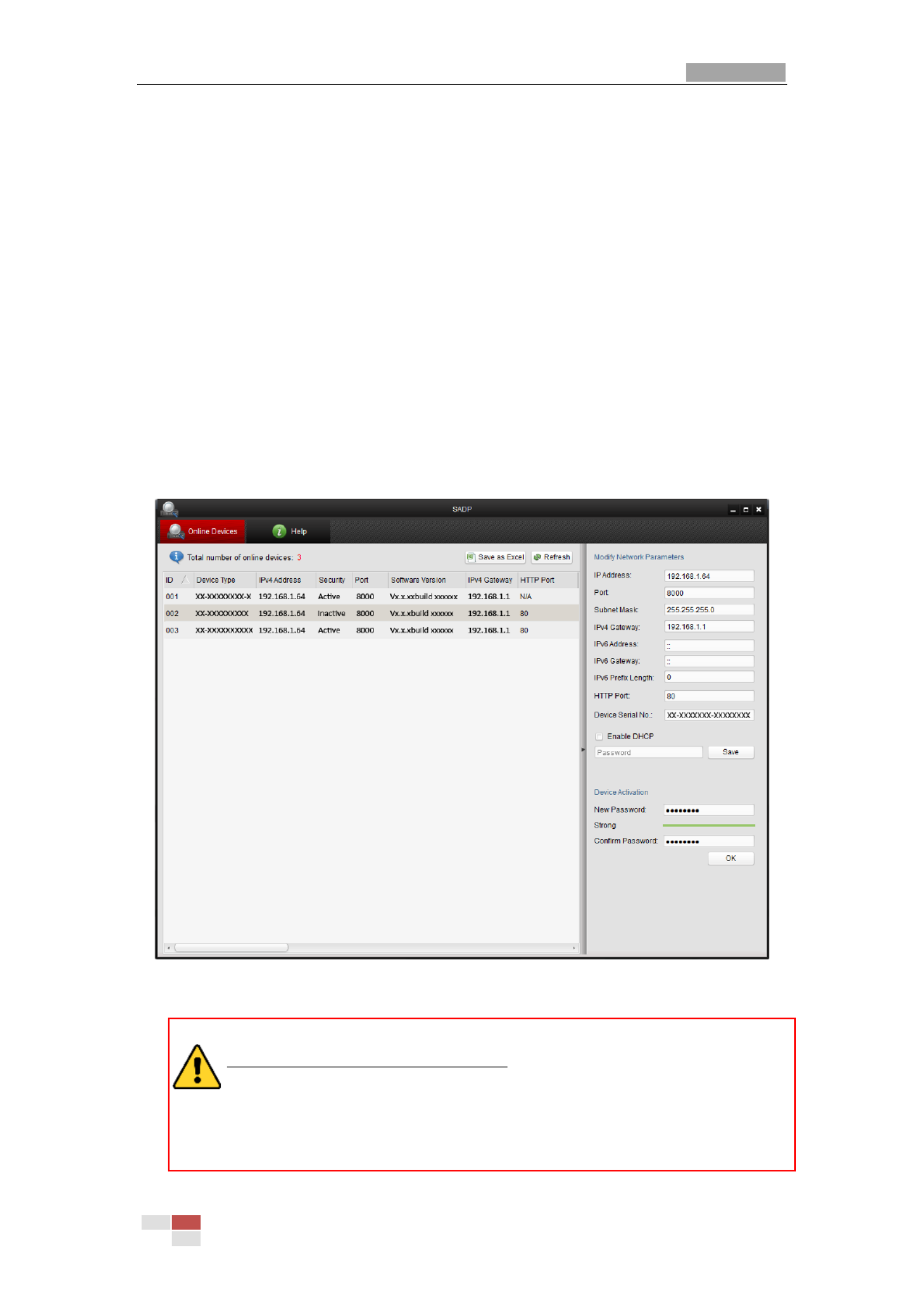
SADP software is used for detecting the online device, activating the device, and resetting
the password.
Get the SADP software from the supplied disk or the official website, and install the SADP
according to the prompts. Follow the steps to activate the speed dome.
.
.
..
St
St
St
StSteps:
eps:
eps:
eps:eps:
1. Run the SADP software to search the online devices.
2. Check the device status from the device list, and select an inactive device.
Figure 2-4 SADP Interface
3. Create a password and input the password in the password field, and confirm the
password.
STRONG
STRONG
STRONG
STRONGSTRONG
PA
PA
PA
PAPASSWORD R
SSWORD R
SSWORD R
SSWORD RSSWORD RE
E
E
EECOMMENDED
COMMENDED
COMMENDED
COMMENDEDCOMMENDED–We highly recommend you create a
strong password of your own choosing (Using a minimum of 8 characters,
including at least three of the following categories: upper case letters, lower
case letters, numbers, and special characters.) in order to increase the
security of your product. And we recommend you reset your password

User Manual of Thermal Network Speed dome
© Hikvision
7
regularly, especially in the high security system, resetting the password
monthly or weekly can better protect your product.
4. Click to save the password.
OK
OK
OK
OKOK
You can check whether the activation is completed on the popup window. If activation
failed, please make sure that the password meets the requirement and then try again.
5. Change the device IP address to the same subnet with your computer by either
modifying the IP address manually or checking the checkbox of .
Enabl
Enabl
Enabl
EnablEnable DHCP
e DHCP
e DHCP
e DHCPe DHCP
Figure 2-5 Modify the IP Address
6. Input the password and click to activate your IP address modification.
Save
Save
Save
SaveSave
A
A
A
AActi
cti
cti
ctictivat
vat
vat
vatvati
i
i
iion v
on v
on v
on von vi
i
i
iia Cl
a Cl
a Cl
a Cla Clie
ie
ie
ieient
nt
nt
ntnt Sof
Sof
Sof
Sof Software
tware
tware
twaretware
The client software is versatile video management software for multiple kinds of devices.
Get the client software from the supplied disk or the official website, and install the
software according to the prompts. Follow the steps to activate the camera.
St
St
St
StSteps:
eps:
eps:
eps:eps:
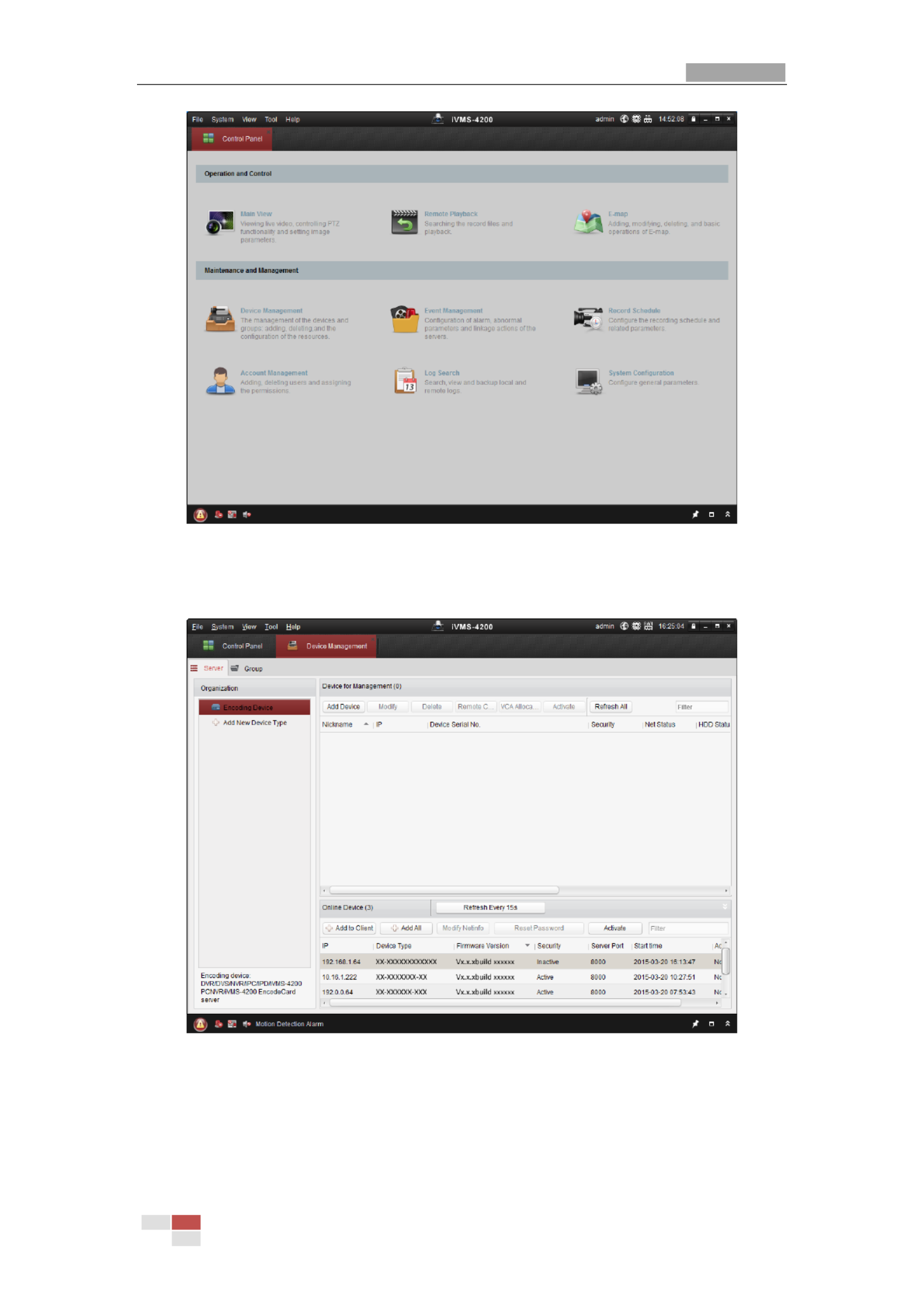
1. Run the client software and the control panel of the software pops up, as shown in the
figure below.
User Manual of Thermal Network Speed dome
© Hikvision
8
Figure 2-6 Control Panel
2. Click to enter the Device Management interface, as shown in the
Devi
Devi
Devi
DeviDevice Ma
ce Ma
ce Ma
ce Mace Management
nagement
nagement
nagementnagement
figure below.
Figure 2-7 Device Management Interface
3. Check the device status from the device list, and select an inactive device.
4. Click to pop up the Activation interface.
Act
Act
Act
ActActi
i
i
iivate
vate
vate
vatevate
5. Create a password and input the password in the password field, and confirm the
password.

User Manual of Thermal Network Speed dome
© Hikvision
9
STRONG
STRONG
STRONG
STRONGSTRONG
PA
PA
PA
PAPASSWORD
SSWORD
SSWORD
SSWORD SSWORD R
R
R
RRECOMMENDED
ECOMMENDED
ECOMMENDED
ECOMMENDEDECOMMENDED–We highly recommend you create a
strong password of your own choosing (Using a minimum of 8 characters,
including at least three of the following categories: upper case letters, lower
case letters, numbers, and special characters.) in order to increase the security
of your product. And we recommend you reset your password regularly,
especially in the high security system, resetting the password monthly or
weekly can better protect your product.
Figure 2-8 Activation Interface
6. Click to start activation.
OK
OK
OK
OKOK
7. Click to pop up the Network Parameter Modification interface, as
Mo
Mo
Mo
MoModi
di
di
didify
fy
fy
fyfy Neti
Neti
Neti
Neti Netinfo
nfo
nfo
nfo nfo
shown in the figure below.
Figure 2-9 Modifying the Network Parameters
8. Change the device IP address to the same subnet with your computer by either
modifying the IP address manually or checking the checkbox of .
Ena
Ena
Ena
EnaEnabl
bl
bl
blble DHCP
e DHCP
e DHCP
e DHCPe DHCP
9. Input the password to activate your IP address modification.

User Manual of Thermal Network Speed dome
© Hikvision
10
2.2 Se
Se
Se
SeSet
t
t
ttt
t
t
tti
i
i
iin
n
n
nng t
g t
g t
g tg th
h
h
hhe
e
e
e e Ne
Ne
Ne
NeNet
t
t
ttw
w
w
wwor
or
or
orork
k
k
kk Sp
Sp
Sp
Sp Spee
ee
ee
eeeed
d
d
d d dome o
dome o
dome o
dome odome ove
ve
ve
vever t
r t
r t
r tr th
h
h
hhe W
e W
e W
e We WAN
AN
AN
ANAN
Pu
Pu
Pu
PuPurpose
rpose
rpose
rposerpose:
:
:
::
This section explains how to connect the network speed dome to the WAN with a static IP
or a dynamic IP.
2.2.1 St
St
St
StStat
at
at
atati
i
i
iic IP
c IP
c IP
c IPc IP
Conn
Conn
Conn
ConnConnect
ect
ect
ectecti
i
i
iion
on
on
onon
Be
Be
Be
BeBefore you
fore you
fore you
fore youfore you st
st
st
st start
art
art
artart:
:
:
::
Please apply a static IP from an ISP (Internet Service Provider). With the static IP address,
you can connect the network speed dome via a router or connect it to the WAN directly.
Connec
Connec
Connec
ConnecConnecti
ti
ti
titing t
ng t
ng t
ng tng the n
he n
he n
he nhe network
etwork
etwork
etworketwork
speed
speed
speed
speedspeed dome vi
dome vi
dome vi
dome vi dome via a
a a
a a
a a a a route
route
route
routerouter
r
r
r r
St
St
St
StSteps:
eps:
eps:
eps:eps:
1. Connect the network speed dome to the router.
2. Assign a LAN IP address, the subnet mask and the gateway. Refer to for
S
S
S
SSect
ect
ect
ectecti
i
i
iion
on
on
on on 2.
2.
2.
2.2.1.
1.
1.
1.1.2
2
2
2 2
detailed IP address configuration of the speed dome.
3. Save the static IP in the router.
4. Set port mapping, E.g., 80, 8000 and 554 ports. The steps for port mapping vary
depending on different routers. Please call the router manufacturer for assistance with
port mapping.
5. Visit the network speed dome through a web browser or the client software over the
internet.
Speed Dome
Network
Cable
Router with Static IP
PC
Network
Cable
Network
Cable
Internet
Figure 2-10 Accessing the Speed dome through Router with Static IP
Connec
Connec
Connec
ConnecConnecti
ti
ti
titing t
ng t
ng t
ng tng the n
he n
he n
he nhe network
etwork
etwork
etworketwork
speed
speed
speed
speedspeed dome wit
dome wit
dome wit
dome wit dome with st
h st
h st
h sth stati
ati
ati
atiatic
c
c
cc IP d
IP d
IP d
IP d IP di
i
i
iirectl
rectl
rectl
rectlrectly
y
y
yy
You can also save the static IP in the speed dome and directly connect it to the internet
without using a router. Refer to for detailed IP address configuration of the
S
S
S
SSecti
ecti
ecti
ectiection
on
on
onon
2.
2.
2.
2.2.1
1
1
11.
.
.
..2
2
2
22
speed dome.

User Manual of Thermal Network Speed dome
© Hikvision
11
Speed Dome
PC
Network
Cable
Network
Cable
Internet
Figure 2-11 Accessing the Speed dome with Static IP Directly
2.2.2 Dyn
Dyn
Dyn
DynDynami
ami
ami
amiamic I
c I
c I
c Ic IP
P
P
PP Conn
Conn
Conn
Conn Connect
ect
ect
ectecti
i
i
iio
o
o
oon
n
n
nn
Be
Be
Be
BeBefore you
fore you
fore you
fore youfore you st
st
st
st start
art
art
artart:
:
:
::
Please apply a dynamic IP from an ISP. With the dynamic IP address, you can connect the
network speed dome to a modem or a router.
Connec
Connec
Connec
ConnecConnecti
ti
ti
titing t
ng t
ng t
ng tng the n
he n
he n
he nhe network
etwork
etwork
etworketwork
speed
speed
speed
speedspeed dome vi
dome vi
dome vi
dome vi dome via a rou
a a rou
a a rou
a a roua a route
te
te
teter
r
r
r r
St
St
St
StSteps:
eps:
eps:
eps:eps:
1. Connect the network speed dome to the router.
2. In the speed dome, assign a LAN IP address, the subnet mask and the gateway. Refer
to for detailed LAN configuration.
Sect
Sect
Sect
SectSecti
i
i
iion 2
on 2
on 2
on 2on 2.
.
.
..1.
1.
1.
1.1.2
2
2
22
3. In the router, set the PPPoE user name, password and confirm the password.
For your privacy and to better protect your system against security risks, we
strongly recommend the use of strong passwords for all functions and network
devices. The password should be something of your own choosing (using a
minimum of 8 characters, including upper case letters, lower case letters, numbers
and special characters) in order to increase the security of your product.
Proper configuration of all passwords and other security settings is the
responsibility of the installer and/or end-user.
4. Set port mapping. E.g. 80, 8000 and 554 ports. The steps for port mapping vary
depending on different routers. Please call the router manufacturer for assistance with
port mapping.
5. Apply a domain name from a domain name provider.
6. Configure the DDNS settings in the setting interface of the router.
7. Visit the speed dome via the applied domain name.
Connec
Connec
Connec
ConnecConnecti
ti
ti
titing t
ng t
ng t
ng tng the n
he n
he n
he nhe network
etwork
etwork
etworketwork
speed
speed
speed
speedspeed dome vi
dome vi
dome vi
dome vi dome via a modem
a a modem
a a modem
a a modem a a modem
Pu
Pu
Pu
PuPurpose
rpose
rpose
rposerpose:
:
:
::
This speed dome supports the PPPoE auto dial-up function. The speed dome gets a public
IP address by ADSL dial-up after the speed dome is connected to a modem. You need to
configure the PPPoE parameters of the network speed dome. Refer to Secti
Secti
Secti
SectiSection
on
on
on on 7.
7.
7.
7.7.1
1
1
11.
.
.
..1
1
1
1 1
Conf
Conf
Conf
ConfConfi
i
i
iiguri
guri
guri
guriguring P
ng P
ng P
ng Png PPP
PP
PP
PPPPoE Set
oE Set
oE Set
oE SetoE Setti
ti
ti
titings
ngs
ngs
ngs ngs for detailed configuration.

User Manual of Thermal Network Speed dome
© Hikvision
12
Figure 2-12 Accessing the Speed dome with Dynamic IP
The obtained IP address is dynamically assigned via PPPoE, so the IP address always
changes after rebooting the speed dome. To solve the inconvenience of the dynamic IP,
you need to get a domain name from the DDNS provider (E.g. DynDns.com). Please
follow below steps for normal domain name resolution and private domain name
resolution to solve the problem.
Normal Domain Name Resolution
Figure 2-13 Normal Domain Name Resolution
St
St
St
StSteps:
eps:
eps:
eps:eps:
1. Apply a domain name from a domain name provider.
2. Configure the DDNS settings in the interface of the network speed
DDNS
DDNS
DDNS
DDNS DDNS Set
Set
Set
SetSett
t
t
tti
i
i
iings
ngs
ngs
ngsngs
dome. Refer to Secti
Secti
Secti
SectiSection
on
on
onon 7.
7.
7.
7. 7.1
1
1
11.
.
.
..1
1
1
11 Conf
Conf
Conf
Conf Config
ig
ig
igiguri
uri
uri
uriuring
ng
ng
ngng DDN
DDN
DDN
DDN DDNS S
S S
S S
S SS Setti
etti
etti
ettiettings
ngs
ngs
ngsngs for detailed configuration.
3. Visit the speed dome via the applied domain name.
Private Domain Name Resolution
Figure 2-14 Private Domain Name Resolution

User Manual of Thermal Network Speed dome
© Hikvision
13
St
St
St
StSteps:
eps:
eps:
eps:eps:
1. Install and run the IP Server software in a computer with a static IP.
2. Access the network speed dome through the LAN with a web browser or the client
software.
3. Enable DDNS and select IP Server as the protocol type. Refer to S
S
S
SSecti
ecti
ecti
ectiection
on
on
on on 7
7
7
77.
.
.
..1.
1.
1.
1.1.1
1
1
1 1
Conf
Conf
Conf
ConfConfi
i
i
iiguri
guri
guri
guriguring
ng
ng
ng ng DDNS Set
DDNS Set
DDNS Set
DDNS SetDDNS Setti
ti
ti
titings
ngs
ngs
ngsngs for detailed configuration.

User Manual of Thermal -spectrum Network Speed dome Bi
© Hikvision
14
Chap
Chap
Chap
ChapChapt
t
t
tter
er
er
erer 3
3
3
3 3
A
A
A
AAcce
cce
cce
ccecces
s
s
sss
s
s
s s t
t
t
tto t
o t
o t
o to th
h
h
hhe
e
e
e e N
N
N
NNet
et
et
etetwor
wor
wor
worwork
k
k
kk
Sp
Sp
Sp
SpSpee
ee
ee
eeeed d
d d
d d
d dd dom
om
om
omome
e
e
ee
3.
3.
3.
3.3.1
1
1
11 A
A
A
AAcces
cces
cces
ccesccessi
si
si
sisin
n
n
nng b
g b
g b
g bg by
y
y
y y W
W
W
WWeb
eb
eb
ebeb B
B
B
B Browse
rowse
rowse
rowserowsers
rs
rs
rs rs
St
St
St
StSteps:
eps:
eps:
eps:eps:
1. Open the web browser.
2. In the address field, input the IP address of the network speed dome, e.g., 192.168.1.64
and press the key to enter the login interface.
Ent
Ent
Ent
EntEnter
er
er
erer
3. Activate the speed dome for the first time using, refer to the secti
secti
secti
sectisection
on
on
onon
2.
2.
2.
2.2.1.
1.
1.
1.1.2
2
2
2 2 Act
Act
Act
ActActiv
iv
iv
ivivati
ati
ati
atiating
ng
ng
ng ng
th
th
th
ththe Speed
e Speed
e Speed
e Speed e Speed dom
dom
dom
domdome
e
e
ee.
4. Select English as the interface language on the top-right of login interface.
5. Input the user name and password and click .
The admin user should configure the device accounts and user/operator permissions
properly. Delete the unnecessary accounts and user/operator permissions.
The device IP address gets locked if the admin user performs 7 failed password
attempts (5 attempts for the user/operator).
Figure 3-1 Login Interface
6. Install the plug-in before viewing the live video and operating the speed dome. Please
follow the installation prompts to install the plug- . in
You may have to close the web browser to install the plug-in. Please reopen the web
browser and log in again after installing the plug-in.

User Manual of Thermal Network Speed dome
© Hikvision
15
Figure 3-2 Download and Install Plug-in
3.
3.
3.
3.3.2
2
2
22 A
A
A
AAcce
cce
cce
ccecces
s
s
sss
s
s
ssi
i
i
iing
ng
ng
ngng b
b
b
b by
y
y
yy
Cl
Cl
Cl
ClCli
i
i
iien
en
en
enent
t
t
tt S
S
S
S Sof
of
of
ofoft
t
t
ttware
ware
ware
wareware
The product CD contains the client software. You can view the live video and manage the
speed dome with the client software.
Follow the installation prompts to install the client software and WinPcap. The
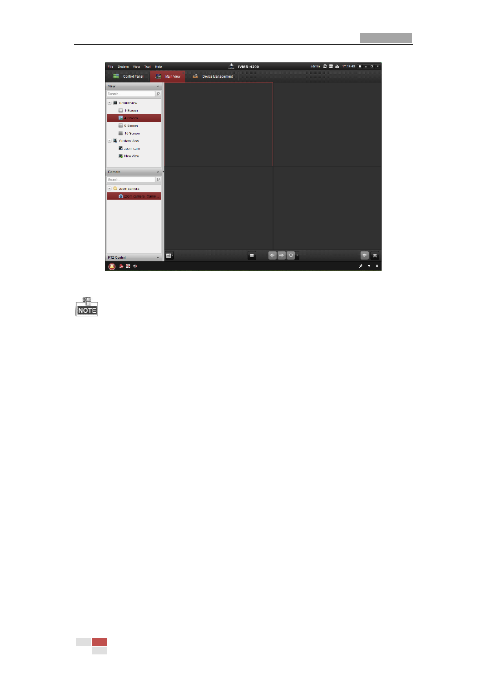
configuration interface and live view interface of client software are shown bel . ow
Figure 3-3 iVMS-4200 Control Panel
User Manual of Thermal Network Speed dome
© Hikvision
16
Figure 3-4 iVMS-4200 Live View Interface
If you use third party VMS software, please contact technical support of our branch
for camera firmware.
For detailed information about client software of our company, please refer to the
user manual of the software. This manual mainly introduces accessing to the network
speed dome by web browser.
User Manual of Thermal -spectrum Network Speed dome Bi
© Hikvision
17
Chap
Chap
Chap
ChapChapt
t
t
tter
er
er
erer 4
4
4
4 4
B
B
B
BBas
as
as
asasi
i
i
iic
c
c
c c Ope
Ope
Ope
OpeOperat
rat
rat
ratrati
i
i
iio
o
o
oons
ns
ns
nsns
In this and the following chapters, operation of the speed dome by the web browser will be
taken as an example.
4.
4.
4.
4.4.1
1
1
11 Conf
Conf
Conf
ConfConfi
i
i
iig
g
g
gguri
uri
uri
uriuring
ng
ng
ngng Local
Local
Local
Local Local P
P
P
P Para
ara
ara
araaram
m
m
mmet
et
et
eteter
er
er
erers
s
s
ss
The local configuration refers to the parameters of the live view and other operations
using the web browser.
St
St
St
StSteps:
eps:
eps:
eps:eps:
1. Enter the Local Configuration interface:
Conf
Conf
Conf
ConfConfigura
igura
igura
iguraigurati
ti
ti
tition > Local
on > Local
on > Local
on > Localon > Local
Figure 4-1 Local Configuration Interface
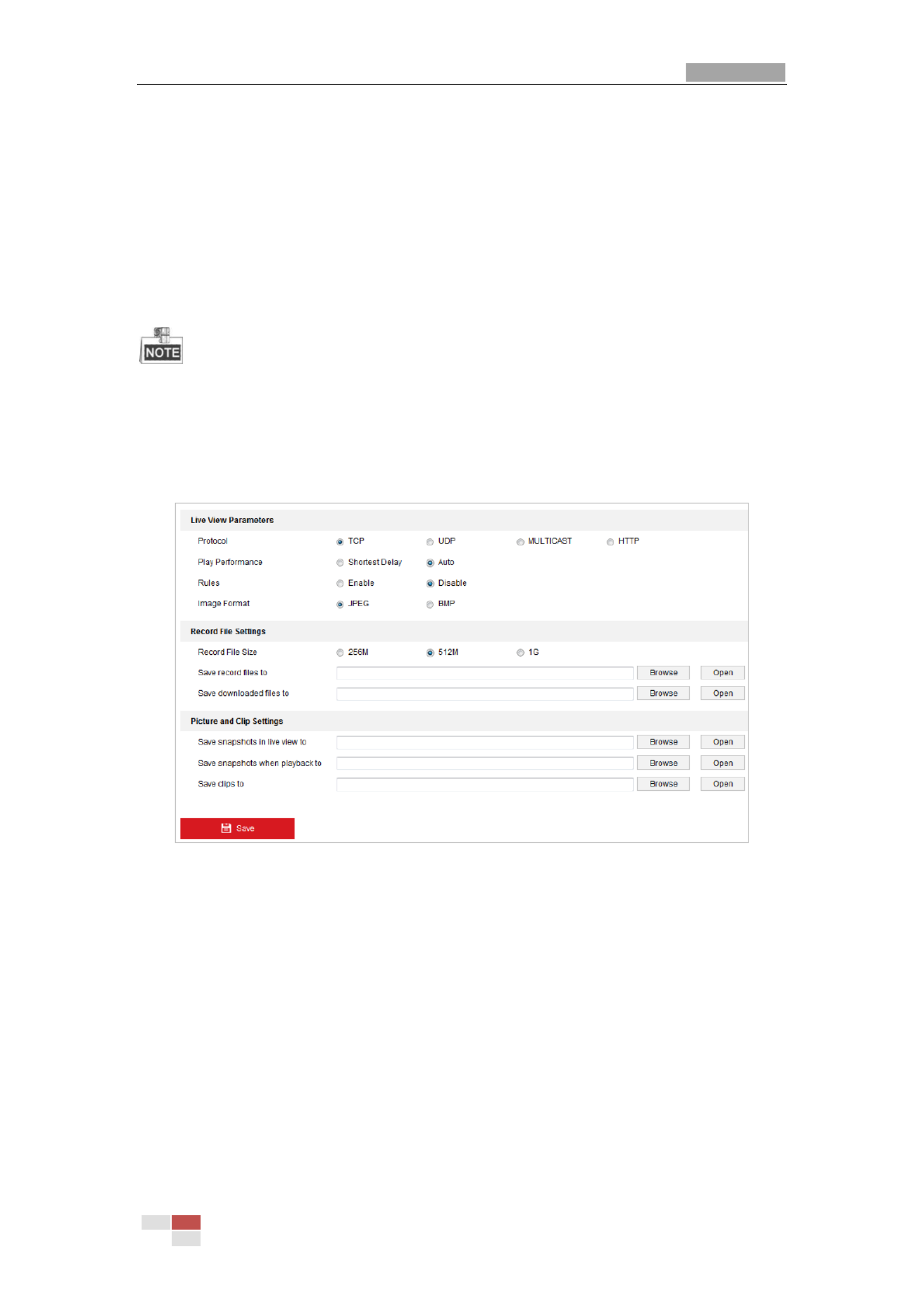
2. Configure the following settings:
Li
Li
Li
LiLive V
ve V
ve V
ve Vve Vi
i
i
iiew Pa
ew Pa
ew Pa
ew Paew Param
ram
ram
ramrame
e
e
eeters:
ters:
ters:
ters:ters:
Set the protocol type, play performance, rules and image
format.
Pro
Pro
Pro
ProProtocol
tocol
tocol
tocoltocol T
T
T
T Type:
ype:
ype:
ype:ype: TCP, UDP, MULTICAST and HTTP are selectable.
TC
TC
TC
TCTCP
P
P
PP
:
:
:
:: Ensures complete delivery of streaming data and better video quality, yet the
real-time transmission will be affected.
UDP
UDP
UDP
UDPUDP
:
:
:
:: Provides real-time audio and video streams.
MUL
MUL
MUL
MULMULTICAST
TICAST
TICAST
TICASTTICAST
:
:
:
:: It’s recommended to select the protocol type to MU
MU
MU
MUMUL
L
L
LL
TICAST
TICAST
TICAST
TICASTTICAST when
using the Multicast function.
HTT
HTT
HTT
HTTHTTP
P
P
PP
:
:
:
:: Allows the same quality as of TCP without setting specific ports for
streaming under some network environments.
Pl
Pl
Pl
PlPlay
ay
ay
ay ay Performance:
Performance:
Performance:
Performance:Performance: Set the play performance to Shortest Delay, or Auto.
User Manual of Thermal Network Speed dome
© Hikvision
18
Rul
Rul
Rul
RulRules:
es:
es:
es:es: You can enable or disable the rules of dynamic analysis for motion here.
Image Format:
Image Format:
Image Format:
Image Format:Image Format: The captured pictures can be saved as different format. JPEG and
BMP are available.
Record Fi
Record Fi
Record Fi
Record FiRecord Fil
l
l
lle S
e S
e S
e Se Set
et
et
etetti
ti
ti
titin
n
n
nngs:
gs:
gs:
gs:gs: Set the saving path of the video files.
Record
Record
Record
Record Record Fi
Fi
Fi
FiFil
l
l
lle
e
e
ee
Si
Si
Si
SiSize:
ze:
ze:
ze:ze:
Select the packed size of manually recorded and downloaded
video files. The size can be set to 256M, 512M or 1G.
Save
Save
Save
Save Save record f
record f
record f
record frecord fi
i
i
iil
l
l
lles
es
es
es es to:
to:
to:
to:to:
Set the saving path for the manually recorded video files.
Save
Save
Save
Save Save d
d
d
ddownl
ownl
ownl
ownlownloaded
oaded
oaded
oadedoaded
fi
fi
fi
fifil
l
l
lle
e
e
ees
s
s
s s to:
to:
to:
to:to:
Set the saving path for the downloaded video files in
interface.
Pi
Pi
Pi
PiPicture
cture
cture
cture cture and
and
and
and and Cl
Cl
Cl
ClClip
ip
ip
ipip
S
S
S
SSett
ett
ett
ettetti
i
i
iings:
ngs:
ngs:
ngs:ngs:
Set the saving paths of the captured pictures and clipped
video files.
Save
Save
Save
Save Save snaps
snaps
snaps
snapssnapshot
hot
hot
hothots
s
s
s s in
in
in
inin
l
l
l
lli
i
i
iive
ve
ve
ve ve vi
vi
vi
vivie
e
e
eew
w
w
w w to:
to:
to:
to:to: Set the saving path of the manually captured
pictures in interface.
Save
Save
Save
Save Save snapsh
snapsh
snapsh
snapshsnapshots
ots
ots
otsots when p
when p
when p
when p when pl
l
l
llayb
ayb
ayb
aybayback
ack
ack
ackack
to:
to:
to:
to:to:
Set the saving path of the captured pictures in
interface.
Save
Save
Save
Save Save cl
cl
cl
clcli
i
i
iips
ps
ps
ps ps to:
to:
to:
to:to:
Set the saving path of the clipped video files in
interface.
You can click to change the directory for saving video files, clips and
Browse
Browse
Browse
BrowseBrowse
pictures.
You can click directly open the video files, clips and pictures.
Open
Open
Open
OpenOpen to
3. Click to save the settings.
4.
4.
4.
4.4.2
2
2
22 Li
Li
Li
LiLive
ve
ve
ve ve V
V
V
VVi
i
i
iiew P
ew P
ew P
ew Pew Page
age
age
ageage
Pu
Pu
Pu
PuPurpose
rpose
rpose
rposerpose:
:
:
::
The live video page allows you to view live video, capture images, realize PTZ control,
set/call presets and configure video parameters.
Log in the network speed dome to enter the live view page, or you can click on
the menu bar of the main page to enter the live view page.

User Manual of Thermal Network Speed dome
© Hikvision
19
Descri
Descri
Descri
DescriDescript
pt
pt
ptption
ion
ion
ionions of t
s of t
s of t
s of ts of the l
he l
he l
he lhe liv
iv
iv
ivive vi
e vi
e vi
e vie view page:
ew page:
ew page:
ew page:ew page:
Live View
Parameters
Live View Window
Toolbar
Show or hide
PTZ control
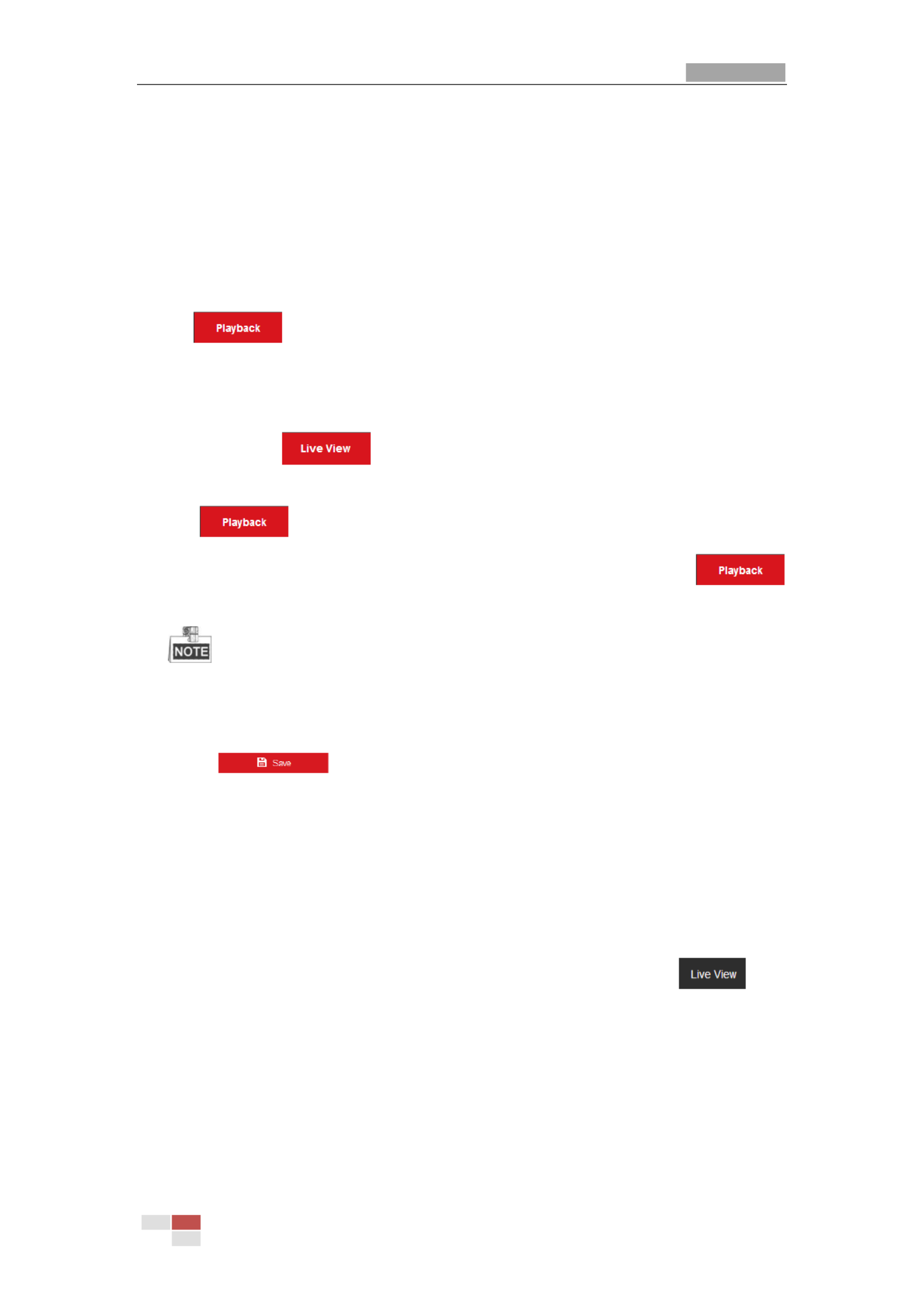
panel
PTZ Control
Preset/Patrol/Pattern
Menu Bar
Figure 4-2 Live View Page
Menu
Menu
Menu
MenuMenu Bar:
Bar:
Bar:
Bar: Bar:
Click each tab to enter Live View, Playback, Picture, and Configuration page respectively.
Click to display the help file of the speed dome.
Click to logout the system.
Li
Li
Li
LiLive V
ve V
ve V
ve Vve View Wind
iew Wind
iew Wind
iew Windiew Window
ow
ow
owow:
:
:
::
Display the live video.
Tool
Tool
Tool
ToolToolbar:
bar:
bar:
bar:bar:
Operations on the live view page, e.g., live view, capture, record, audio on/off, regional
exposure, regional focus, etc.
PTZ Contro
PTZ Contro
PTZ Contro
PTZ ControPTZ Control:
l:
l:
l:l:
Panning, tilting, focusing and zooming actions of the speed dome. The lighter, wiper,
one-touch focus and lens initialization control.
Pr
Pr
Pr
PrPreset/
eset/
eset/
eset/eset/patrol
patrol
patrol
patrolpatrol/pat
/pat
/pat
/pat/pattern
tern
tern
terntern:
:
:
::
Set and call the preset/patrol/pattern for the speed dome.
Pattern function varies depending on the models of speed dome.
Li
Li
Li
LiLive V
ve V
ve V
ve Vve View Par
iew Par
iew Par
iew Pariew Param
am
am
amamete
ete
ete
eteeters:
rs:
rs:
rs:rs:
Configure the image size, stream type, plug-in type, and two-way audio of the live video.
4.
4.
4.
4.4.3
3
3
33 St
St
St
StStar
ar
ar
arart
t
t
tti
i
i
iing
ng
ng
ng ng Li
Li
Li
LiLive
ve
ve
veve Vi
Vi
Vi
Vi View
ew
ew
ew ew
In the live view window as shown in Figure 4-3, click on the toolbar to start the live
view of the speed dome.

User Manual of Thermal Network Speed dome
© Hikvision
20
Figure 4-3 Start Live View
Table 4-1 Descriptions of the Toolbar
Ico
Ico
Ico
IcoIcon
n
n
n n
Descri
Descri
Descri
DescriDescript
pt
pt
ptpti
i
i
iion
on
on
onon
Ico
Ico
Ico
IcoIcon
n
n
n n
Descri
Descri
Descri
DescriDescript
pt
pt
ptpti
i
i
iion
on
on
onon
/
Start/Stop Live view.
Manually capture the
pictures.
/ /
/
Display in 4:3/16:9/original/
Self-adaptive window size.
/ /
Live view with the
main/sub/third stream.
/
Play via webcomponents/
quick time.
/
Start/Stop Two-way Audio.
/
Manual start/stop
recording.
/
Mute/Audio on and adjust
volume
/
Start/stop digital zoom.
/
Enable/Disable Regional
Exposure
/
Enable / Disable Regional
Focus
Double-click on the live video to switch the current live view into full-screen or return to
normal mode from the full-screen.
Click to select from and display live video in 4:3/16:9/
original/self-adaptive window size.
Click to select from and display live video with the main/
sub/third stream. The main stream is with a relatively high resolution and needs much
bandwidth. The default setting of stream type is .

User Manual of Thermal Network Speed dome
© Hikvision
21
Click to select betwee and play the live video via player n
We
We
We
WeWebcomponent
bcomponent
bcomponent
bcomponentbcomponents
s
s
s s Qui
Qui
Qui
QuiQuick Ti
ck Ti
ck Ti
ck Tick Time
me
me
memeor . The live video is played via webcomponents by default,
and other types of players are supported for the browser, such as MJPEG, and VLC. You
are required to download and install the player to play the live video.
Click and it displays . Click to enable two-way audio and the icon turns
into . Click the icon again to stop two-way audio.
Click to start live view and the icon turns into . Click the icon again to stop live
view.
Click to capture the picture.
Click to start recording and the icon turns into . Click the icon again to stop
recording.
Click to enable digital zoom function and the icon turns into . Then click and
drag the mouse towards low right direction to draw a rectangle on the image as the
desired zoom. After viewing it you can click any place of the picture to get back to
normal picture.
Click the on the toolbar to enter the regional exposure operation mode and the
icon turns into . Then click and drag the mouse to draw a rectangle on the image
as the desired exposure region.
Click the on the toolbar to enter the regional focus operation mode and the icon
turns into . Then click and drag the mouse to draw a rectangle on the image as the
desired focus region.
Click to display the . Drag the slider to adjust the volumn.
Before using the two-way audio or recording with audio functions please set the , St
St
St
StStream
ream
ream
reamream
T
T
T
TTy
y
y
yype
pe
pe
pepe Vi
Vi
Vi
ViVideo
deo
deo
deodeo & A
& A
& A
& A & Audi
udi
udi
udiudio
o
o
oo to referring to .
Secti
Secti
Secti
Secti Section
on
on
onon 7.
7.
7.
7.7.2.
2.
2.
2.2.1 Conf
1 Conf
1 Conf
1 Conf1 Configu
igu
igu
iguigurin
rin
rin
rinring Vi
g Vi
g Vi
g Vig Video S
deo S
deo S
deo Sdeo Sett
ett
ett
ettetting
ing
ing
ingings
s
s
ss
Please refer to the following sections for more information:
Configuring remote recording in Secti
Secti
Secti
SectiSection 5
on 5
on 5
on 5on 5.
.
.
..1.
1.
1.
1.1.1 Conf
1 Conf
1 Conf
1 Conf1 Configu
igu
igu
iguiguri
ri
ri
riring R
ng R
ng R
ng Rng Record
ecord
ecord
ecordecording
ing
ing
inging Schedul
Schedul
Schedul
Schedul Schedule
e
e
ee.
Setting the image quality of the live video in Sect
Sect
Sect
SectSectio
io
io
ioion 7.
n 7.
n 7.
n 7.n 7.4
4
4
44 C
C
C
C Conf
onf
onf
onfonfigu
igu
igu
iguiguring
ring
ring
ringring Image Sett
Image Sett
Image Sett
Image Sett Image Setti
i
i
iings
ngs
ngs
ngsngs.
.
.
..
and .
Secti
Secti
Secti
SectiSection
on
on
onon 7.
7.
7.
7.7.2.
2.
2.
2.2.1 Conf
1 Conf
1 Conf
1 Conf1 Config
ig
ig
igiguri
uri
uri
uriuring V
ng V
ng V
ng Vng Video
ideo
ideo
ideoideo Sett
Sett
Sett
Sett Setti
i
i
iings
ngs
ngs
ngsngs
Setting the OSD text on live video i . n Sect
Sect
Sect
SectSection
ion
ion
ionion 7.
7.
7.
7.7.4.
4.
4.
4.4.2 Con
2 Con
2 Con
2 Con2 Confi
fi
fi
fifiguri
guri
guri
guriguring OSD Se
ng OSD Se
ng OSD Se
ng OSD Seng OSD Sett
tt
tt
ttttings
ings
ings
ingsings
4.
4.
4.
4.4.4
4
4
44 Op
Op
Op
OpOpera
era
era
eraerat
t
t
tti
i
i
iing
ng
ng
ngng P
P
P
P PT
T
T
TTZ
Z
Z
Z Z Cont
Cont
Cont
ContContro
ro
ro
rorol
l
l
ll
Pu
Pu
Pu
PuPurpose:
rpose:
rpose:
rpose:rpose:
In the live view interface, you can use the PTZ control buttons to control panning, tilting
and zooming.
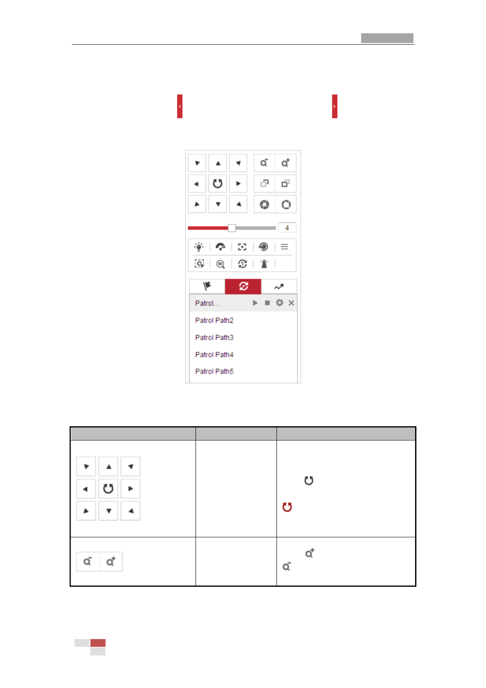
User Manual of Thermal Network Speed dome
© Hikvision
22
4.
4.
4.
4.4.4.
4.
4.
4.4.1
1
1
11 P
P
P
PPTZ
TZ
TZ
TZTZ Cont
Cont
Cont
Cont Control
rol
rol
rolrol P
P
P
P Pa
a
a
aanel
nel
nel
nelnel
On the live view page, click to show the PTZ control panel or click to hide it.
Click the direction buttons to control the pan/tilt movements.
Click the zoom/iris/focus buttons to realize lens control.
Figure 4-4 PTZ Control Panel
Table 4-2 Descriptions of PTZ Control Panel
Bu
Bu
Bu
BuButt
tt
tt
tttton
on
on
on on
Name
Name
Name
Name Name
Descri
Descri
Descri
DescriDescrip
p
p
ppti
ti
ti
tition
on
on
on on
PTZ Control Panel
Hold and press the direction
button to pan/tilt the speed . dome
Click and the speed dome
keeps panning, the icon turns into
. Click the icon again to stop
the speed dome.
Zoom out/in
Click , the lens zooms in, click
, and the lens zooms out.

User Manual of Thermal Network Speed dome
© Hikvision
23
Bu
Bu
Bu
BuButt
tt
tt
tttton
on
on
on on
Name
Name
Name
Name Name
Descri
Descri
Descri
DescriDescrip
p
p
ppti
ti
ti
tition
on
on
onon
Focus near/far
Click , the lens focus far and
the items far away gets clear. Click
, the lens focus near and the
items nearby gets clear.
Iris close/open
When the image is too dark, click
to open the iris. When the
image is too bright, click to
close the iris.
Auxiliary Functions
The auxiliary functions include
light, wiper, auxiliary focus, lens
initialization, manual tracking, 3D
positioning, one-touch patrol, and
one-touch park.
Speed Adjustment
Adjust speed of pan/tilt
movements.
Preset
Refer to for detailed
4.
4.
4.
4.4.4
4
4
44.
.
.
..3
3
3
33
information of setting preset.
Patrol
Refer to for detailed
4.
4.
4.
4.4.4
4
4
44.
.
.
..4
4
4
44
information of setting patrol.
Pattern
Refer to for detailed
4.
4.
4.
4.4.4
4
4
44.
.
.
..6
6
6
66
information of setting pattern.
Bu
Bu
Bu
BuButt
tt
tt
ttttons
ons
ons
onsons on
on
on
on on the
the
the
the the Prese
Prese
Prese
Prese Preset/
t/
t/
t/t/Pat
Pat
Pat
PatPatrol
rol
rol
rolrol/P
/P
/P
/P/Pat
at
at
atattern
tern
tern
ternterns i
s i
s i
s is in
n
n
nnter
ter
ter
terterface
face
face
faceface:
:
:
::
Table 4-3 Descriptions of Buttons
Bu
Bu
Bu
BuButt
tt
tt
ttttons
ons
ons
onsons
Descri
Descri
Descri
DescriDescrip
p
p
ppti
ti
ti
tition
on
on
onon
Start the selected patrol/pattern.
Stop current patrol/pattern.
Set the selected preset/patrol.
Delete the selected preset/patrol/pattern.
Start recording a patte rn.
Stop recording the pattern.
4.
4.
4.
4.4.4.
4.
4.
4.4.2
2
2
22 A
A
A
AAux
ux
ux
uxuxi
i
i
iil
l
l
lli
i
i
iiar
ar
ar
arary
y
y
y y Func
Func
Func
FuncFunct
t
t
tti
i
i
iio
o
o
oons
ns
ns
nsns
The Auxiliary functions panel is shown in the figure below:

User Manual of Thermal Network Speed dome
© Hikvision
24
Figure 4-5 Auxiliary Functions
Light
Click to enable/disable the light supplement of the speed dome. This function is
reserved.
Wiper
Click to move the wiper once.
Auxiliary Focus
The auxiliary focus function is reserved.
Click to enable manual -Icing function of the device. De
The de-icing function takes effect when the device inner temperature is 30° C (86≤°F).
Manual Tracking
Be
Be
Be
BeBefore yo
fore yo
fore yo
fore yofore you s
u s
u s
u su star
tar
tar
tartart
t
t
tt:
:
:
::
Please enter the Smart Tracking settings interface and enable smart tracking first.
Conf
Conf
Conf
ConfConfi
i
i
iigurat
gurat
gurat
guratgurati
i
i
iion >
on >
on >
on >on > PTZ > Smart Tracki
PTZ > Smart Tracki
PTZ > Smart Tracki
PTZ > Smart TrackiPTZ > Smart Trackin
n
n
nng
g
g
gg
St
St
St
StSteps
eps
eps
epseps:
:
:
::
1. Click on the toolbar of live view interface.
2. Click a moving object in the live video.
The speed dome will track the object automatically.
3D Positioning
St
St
St
StSteps
eps
eps
epseps:
:
:
::
1. Click on the toolbar of live view interface.
2. Operate the 3D positioning function:
3. Click a position of the live video. The corresponding position will be moved to the
center of the live video.
4. Hold down the left mouse button and drag the mouse to the lower right on the live
video. The corresponding position will be moved to the center of the live video and
zoomed in.
5. Hold down the left mouse button and drag the mouse to the upper left on the live video.
The corresponding position will be moved to the center of the live video and zoomed
out.

User Manual of Thermal Network Speed dome
© Hikvision
25
One-touch Patrol
Click to call one-touch patrol. For detailed information of setting one-touch
patrol, refer to .
4.
4.
4.
4.4.4.
4.
4.
4.4.5
5
5
55 One-
One-
One-
One- One-touch
touch
touch
touch touch Patrol
Patrol
Patrol
PatrolPatrol
One-touch Park
Click to save the current view as the preset No. 32 and start park at the the
current position.
4.
4.
4.
4.4.4.
4.
4.
4.4.3
3
3
33 Set
Set
Set
SetSett
t
t
tti
i
i
iing
ng
ng
ngng / Cal
/ Cal
/ Cal
/ Cal / Call
l
l
lli
i
i
iing
ng
ng
ngng a
a
a
a a Pre
Pre
Pre
PrePreset
set
set
setset
Pu
Pu
Pu
PuPurpose:
rpose:
rpose:
rpose:rpose:
A preset is a predefined image position. For the defined preset, you can click the calling
button to quickly view the desired image position.
Set
Set
Set
SetSetti
ti
ti
titing a
ng a
ng a
ng ang a Preset
Preset
Preset
Preset Preset:
:
:
::
St
St
St
StSteps:
eps:
eps:
eps:eps:
1. In the PTZ control panel, select a preset number from the preset list.
Figure 4-6 Setting a Preset
2. Use the PTZ control buttons to move the lens to the desired position.
• Pan the speed dome to the right or left.
• Tilt the speed dome up or down.
• Zoom in or out.
• Refocus the lens.
3. Click to finish the setting of the current preset.
4. Edit a preset name by double clicking on the default name such as preset 1. (The pre-defined presets
are named already and not configurable. Please refer to the user manual for detailed function
description.)
5. You can click to delete the preset.
You can configure up to 256 presets.
Cal
Cal
Cal
CalCalli
li
li
liling a
ng a
ng a
ng ang a Pres
Pres
Pres
Pres Pres
et:
et:
et:
et:et:
In the PTZ control panel, select a defined preset from the list and click to call the
preset.

User Manual of Thermal Network Speed dome
© Hikvision
26
Figure 4-7 Calling a Preset
For convenient preset selection, refer to the following steps to navigate to the preset you
want.
St
St
St
StSteps:
eps:
eps:
eps:eps:
1. Select any preset from the list.
2. Click the preset number you need on the keyboard.
The following presets are predefined with special commands. You can only call them
but not congure them. For instance, preset 99 is the “Start auto scan”. If you call the
preset 99, the speed dome starts auto scan function.
Pattern function varies depending on the models of speed dome .
Table 4-4 Special Presets
Pre
Pre
Pre
PrePreset
set
set
setset
Funct
Funct
Funct
FunctFunctio
io
io
ioion
n
n
n n
Pre
Pre
Pre
PrePreset
set
set
setset
Funct
Funct
Funct
FunctFunctio
io
io
ioion
n
n
n n
33
Auto flip
92
Start to set limit stops
34
Back to initial position
93
Set limit stops manually
35
Call patrol 1
94
Remote reboot
36
Call patrol 2
95
Call OSD menu
37
Call patrol 3
96
Stop a scan
38
Call patrol 4
97
Start random scan
39
Day mode (IR cut filter in)
98
Start frame scan
40
Night mode (IR cut filter out)
99
Start auto scan
41
Call pattern 1
100
Start tilt scan
42
Call pattern 2
101
Start panorama scan
43
Call pattern 3
102
Call patrol 5
44
Call pattern 4
103
Call patrol 6
45
One-touch Patrol
104
Call patrol 7
90
Wiper
105
Call patrol 8

User Manual of Thermal Network Speed dome
© Hikvision
27
Figure 4-8 Special Preset
You may need to use the OSD (On Screen Display) menu when controlling the speed
dome remotely. To display the OSD menu on the live view screen, you can call the
preset number 95.
4.
4.
4.
4.4.4.
4.
4.
4.4.4
4
4
44 Set
Set
Set
SetSett
t
t
tti
i
i
iin
n
n
nng /
g /
g /
g /g / Cal
Cal
Cal
Cal Call
l
l
lli
i
i
iing
ng
ng
ngng a P
a P
a P
a P a Pa
a
a
aatro
tro
tro
trotrol
l
l
ll
Pu
Pu
Pu
PuPurpose
rpose
rpose
rposerpose:
:
:
::
A patrol is a memorized series of preset function. It can be configured and called on the
patrol settings interface. There are up to 8 patrols for customizing. A patrol can be
configured with 32 presets.
Be
Be
Be
BeBefore you
fore you
fore you
fore youfore you st
st
st
st start
art
art
artart:
:
:
::
Please make sure that the presets you want to add into a patrol have been defined.
Set
Set
Set
SetSetti
ti
ti
titing
ng
ng
ngng a Pa
a Pa
a Pa
a Pa a Patrol
trol
trol
troltrol:
:
:
::
St
St
St
StSteps:
eps:
eps:
eps:eps:
1. In the PTZ control panel, click to enter the patrol settings interface.
2. Select a patrol number from the list and click .
3. Click to enter the adding interface of preset, as shown in Figure 4-9.

User Manual of Thermal Network Speed dome
© Hikvision
28
Figure 4-9 Adding Presets
4. Configure the preset number, patrol time and patrol speed.
Name
Name
Name
Name Name
Descr
Descr
Descr
DescrDescrip
ip
ip
ipipt
t
t
tti
i
i
iion
on
on
on on
Patrol Time
It is the duration staying on one patrol point. The speed dome
moves to another patrol point after the patrol time.
Patrol Speed
It is the speed of moving from one preset to another.
5. Click to save a preset into the patrol.
OK
OK
OK
OKOK
6. Repeat the steps from 3 to 5 to add more presets.
7. Click to save all the patrol settings.
OK
OK
OK
OKOK
Cal
Cal
Cal
CalCall
l
l
lli
i
i
iing
ng
ng
ngng a P
a P
a P
a P a Pat
at
at
atatrol
rol
rol
rolrol:
:
:
::
In the PTZ control panel, select a defined patrol from the list and click to call the patrol,
as shown in Figure 4- . 10
Figure 4-10 Calling a Preset

User Manual of Thermal Network Speed dome
© Hikvision
29
4.4.5 On
On
On
OnOne-
e-
e-
e-e-t
t
t
tto
o
o
oouch
uch
uch
uchuch Pa
Pa
Pa
Pa Patro
tro
tro
trotrol
l
l
ll
Pu
Pu
Pu
PuPurpose:
rpose:
rpose:
rpose:rpose:
One-touch patrol is an automatically created patrol. The system automatically add preset
No.1 to No.32 to the patrol path 8. You can call the one-touch patrol and the speed dome
moves as the patrol path 8 automatically.
St
St
St
StSteps:
eps:
eps:
eps:eps:
1. Set preset No.1 to No.32. Refer to for detailed
4.
4.
4.
4.4.4
4
4
44.
.
.
..3 S
3 S
3 S
3 S3 Sett
ett
ett
ettetti
i
i
iing / Cal
ng / Cal
ng / Cal
ng / Calng / Call
l
l
lli
i
i
iing a
ng a
ng a
ng a ng a Preset
Preset
Preset
PresetPreset
information of setting preset.
2. Call preset No. 45, and the speed dome moves as patrol path 8.
3. Click to enter the patrol settings interface and start/stop one-touch patrol, edit
the patrol time and the speed.
4. You can click of the PTZ control panel to start one-touch patrol.
Figure 4-11 Patrol Path 8
4.
4.
4.
4.4.4.
4.
4.
4.4.6
6
6
66 Set
Set
Set
SetSett
t
t
tti
i
i
iin
n
n
nng /
g /
g /
g /g / Cal
Cal
Cal
Cal Call
l
l
lli
i
i
iing a
ng a
ng a
ng ang a P
P
P
P Pat
at
at
atatt
t
t
ttern
ern
ern
ernern
Pu
Pu
Pu
PuPurpose:
rpose:
rpose:
rpose:rpose:
A pattern is a memorized series of pan, tilt, zoom, and preset functions. It can be called on
the pattern settings interface. There are up to 4 patterns for customizing.
Pattern function varies depending on speed dome models.
Set
Set
Set
SetSetti
ti
ti
titing
ng
ng
ngng a Pa
a Pa
a Pa
a Pa a Patt
tt
tt
ttttern:
ern:
ern:
ern:ern:
St
St
St
StSteps:
eps:
eps:
eps:eps:
1. In the PTZ control panel, click to enter the pattern settings interface.
2. Select a pattern number from the list as shown in Figure 4- . 12

User Manual of Thermal Network Speed dome
© Hikvision
30
Figure 4-12 Patterns Settings Interface
3. Click to enable recording the panning, tilting and zooming actions.
4. Use the PTZ control buttons to move the lens to the desired position after the
information of PROGR
PROGR
PROGR
PROGRPROGRAM P
AM P
AM P
AM PAM PATTER
ATTER
ATTER
ATTERATTERN REMAINNI
N REMAINNI
N REMAINNI
N REMAINNIN REMAINNING
NG
NG
NGNG MEMORY(
MEMORY(
MEMORY(
MEMORY( MEMORY(%)
%)
%)
%)%) is displayed on the
screen.
Pan the speed dome to the right or left.
Tilt the speed dome up or down.
Zoom in or out.
Refocus the lens.
5. Click to save all the pattern settings.
Bu
Bu
Bu
BuButt
tt
tt
ttttons o
ons o
ons o
ons oons on th
n th
n th
n thn the Pat
e Pat
e Pat
e Pate Patter
ter
ter
terterns i
ns i
ns i
ns ins int
nt
nt
ntnterf
erf
erf
erferface:
ace:
ace:
ace:ace:
Bu
Bu
Bu
BuButt
tt
tt
ttttons
ons
ons
onsons
Descri
Descri
Descri
DescriDescript
pt
pt
ptpti
i
i
iion
on
on
onon
Start the selected patrol/pattern.
Stop current patrol/pattern.
Set the selected preset/patrol.
Delete the selected preset/patrol/pattern.
Start recording a pattern.
Stop recording the pattern.
These 4 patterns can be operated separately and with no priority level.
When configuring and calling the pattern, proportional pan is valid; the limit stops and
auto flip will be invalid; and the 3D positioning operation is not supported.
4.
4.
4.
4.4.5
5
5
55 P
P
P
PPl
l
l
llay
ay
ay
ayayb
b
b
bback
ack
ack
ackack
Pu
Pu
Pu
PuPurpose:
rpose:
rpose:
rpose:rpose:
This section explains how to view the video files stored in the network disks or memory
cards.
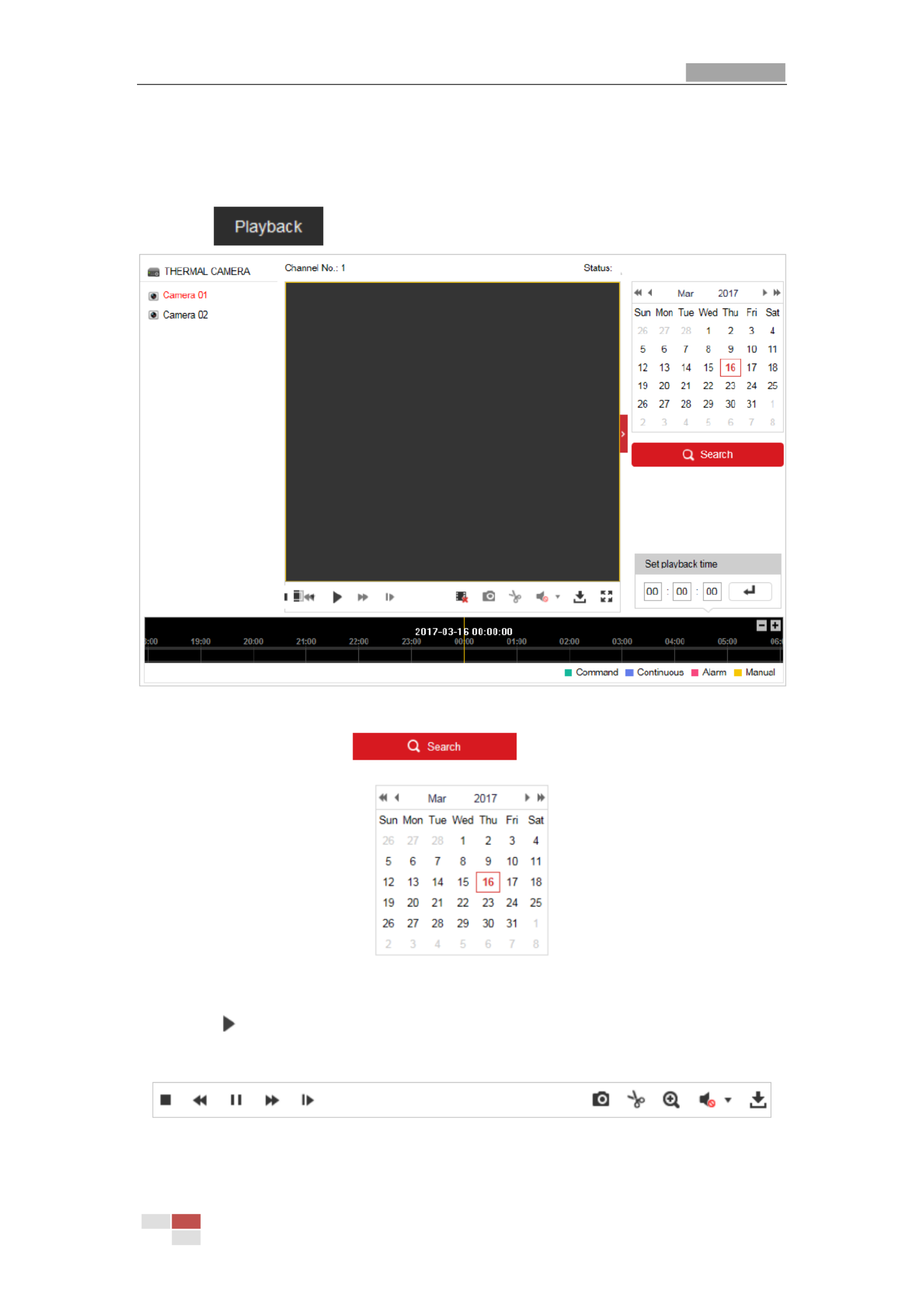
User Manual of Thermal Network Speed dome
© Hikvision
31
4.5.1 P
P
P
PPl
l
l
llay
ay
ay
ayay B
B
B
B Back
ack
ack
ackack
V
V
V
VVi
i
i
iid
d
d
ddeo F
eo F
eo F
eo Feo Fi
i
i
iil
l
l
lles
es
es
eses
St
St
St
StSteps:
eps:
eps:
eps:eps:
1. Click on the menu bar to enter playback interface.
Figure 4-13 Playback Interface
2. Select the date and click .
Figure 4-14 Search Video
3. Click to play the video files found on this date.
The toolbar on the bottom of Playback interface can be used to control playing process.
Figure 4-15 Playback Toolbar

User Manual of Thermal Network Speed dome
© Hikvision
32
Table 4-5 Description of the buttons
Bu
Bu
Bu
BuButt
tt
tt
tttton
on
on
onon
Oper
Oper
Oper
OperOperat
at
at
atati
i
i
iion
on
on
onon
Bu
Bu
Bu
BuButt
tt
tt
tttton
on
on
onon
Oper
Oper
Oper
OperOperat
at
at
atati
i
i
iion
on
on
onon
Play
Capture a picture
Pause
/
Start/Stop clipping
video files
Stop
/
Audio on and
adjust
volume/Mute
Speed down
Download
Speed up
Playback by frame
/
Enable/Disable
digital zoom
You can choose the file paths locally for downloaded playback video files and pictures in
Local Configuration interface. Please refer to Sec
Sec
Sec
SecSecti
ti
ti
titio
o
o
oon
n
n
n n 4.
4.
4.
4.4.1
1
1
1 1 Confi
Confi
Confi
ConfiConfig
g
g
gguri
uri
uri
uriuring
ng
ng
ngng
Loc
Loc
Loc
LocLocal
al
al
alal
P
P
P
PParamete
aramete
aramete
arametearameters
rs
rs
rsrs
for details.
Drag the progress bar with the mouse to locate the exact playback point. You can also
input the time and click to locate the playback point in the field.
Set p
Set p
Set p
Set pSet pl
l
l
llayb
ayb
ayb
aybayback
ack
ack
ackack ti
ti
ti
ti time
me
me
meme
You can also click to zoom out/in the progress bar.
Figure 4-16 Set Playback Time
Figure 4-17 Progress Bar
The different colors of the video on the progress bar stand for the different video types as
shown in Figure 4- . 18
Figure 4-18 Video Types
4.5.2 Downl
Downl
Downl
DownlDownlo
o
o
ooad
ad
ad
adadi
i
i
iin
n
n
nng V
g V
g V
g Vg Vi
i
i
iide
de
de
dedeo Fi
o Fi
o Fi
o Fio Fil
l
l
lles
es
es
eses
St
St
St
StSteps:
eps:
eps:
eps:eps:

User Manual of Thermal Network Speed dome
© Hikvision
33
1. Click on the playback interface. The pop-up menu is shown in Figure 4- . 19
2. Set the start time and end time. Click . The corresponding video files are listed
Searc
Searc
Searc
SearcSearch
h
h
hh
on the left.
Figure 4-19 Video Downloading interface
3. Check the checkbox in front of the video files that you need to download.
4. Click to download the video files.
4.
4.
4.
4.4.6
6
6
66 P
P
P
PPi
i
i
iict
ct
ct
ctctur
ur
ur
urures
es
es
eses
Pu
Pu
Pu
PuPurpose:
rpose:
rpose:
rpose:rpose:
This section explains how to view the captured picture files stored in the network disks or
the memory cards and download the captured pictures.
St
St
St
StSteps:
eps:
eps:
eps:eps:
1. Click on the menu bar to enter picture interface.

User Manual of Thermal Network Speed dome
© Hikvision
34
Figure 4-20 Picture Interface
2. Select the file type of capturing the pictures from the list as timing, alarm, motion, etc.
3. Set the start time and end time. Click . The corresponding picture files will be
Sea
Sea
Sea
SeaSearch
rch
rch
rchrch
listed.
4. Check the checkbox in front of the files that you need to download.
5. Click to download the files.
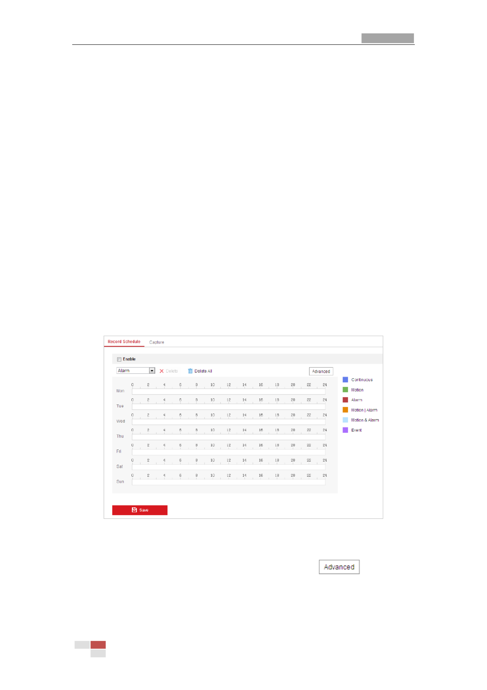
User Manual of Thermal -spectrum Network Speed dome Bi
© Hikvision
35
Chap
Chap
Chap
ChapChapt
t
t
tter
er
er
erer 5
5
5
5 5
Sy
Sy
Sy
SySys
s
s
sst
t
t
ttem C
em C
em C
em Cem Con
on
on
ononf
f
f
ffi
i
i
iig
g
g
ggur
ur
ur
ururat
at
at
atati
i
i
iion
on
on
onon
5.
5.
5.
5.5.1
1
1
11 St
St
St
StStor
or
or
ororage
age
age
ageage Se
Se
Se
Se Sett
tt
tt
tttti
i
i
iing
ng
ng
ngngs
s
s
ss
Be
Be
Be
BeBefore you s
fore you s
fore you s
fore you sfore you start
tart
tart
tarttart:
:
:
::
To configure record settings, please make sure that you have the network storage device
within the network or the memory card inserted in your speed dome.
5.
5.
5.
5.5.1.
1.
1.
1.1.1
1
1
11 Conf
Conf
Conf
ConfConfi
i
i
iigur
gur
gur
gurguri
i
i
iing Record
ng Record
ng Record
ng Recordng Recordi
i
i
iing
ng
ng
ng ng Sched
Sched
Sched
SchedSchedul
ul
ul
ulule
e
e
ee
Pu
Pu
Pu
PuPurpose:
rpose:
rpose:
rpose:rpose:
There are two kinds of recording for the speed domes: manual recording and scheduled
recording. In this section, you can follow the instructions to configure the scheduled
recording. By default, the record files of scheduled recording are stored in the memory
card (if supported) or in the network disk.
St
St
St
StSteps:
eps:
eps:
eps:eps:
1. Enter the Record Schedule settings interface:
Conf
Conf
Conf
ConfConfigura
igura
igura
iguraigurati
ti
ti
tition > St
on > St
on > St
on > Ston > Storage
orage
orage
orageorage > Schedul
> Schedul
> Schedul
> Schedul > Schedule S
e S
e S
e Se Setti
etti
etti
ettiettings
ngs
ngs
ngsngs > Record Schedu
> Record Schedu
> Record Schedu
> Record Schedu > Record Schedule
le
le
lele
Figure 5-1 Recording Schedule Interface
2. Check the checkbox of to enable scheduled recording.
Enabl
Enabl
Enabl
Enabl Enable
e
e
e e
3. To set the advanced settings of the speed dome, click to enter the
advanced settings interface.

User Manual of Thermal Network Speed dome
© Hikvision
36
Figure 5-2 Record Parameters
Pre
Pre
Pre
PrePre-re
-re
-re
-re-record:
cord:
cord:
cord:cord:
The time you set to start recording before the scheduled time or the
event. For example, if an alarm triggers recording at 10:00, and the pre-record time
is set as 5 seconds, the speed dome starts to record at 9:59:55.
The Pre-record time can be configured as No Pre-record, 5 s, 10 s, 15 s, 20 s, 25 s,
30 s or not limited.
The pre-record time changes according to the video bitrate.
Pos
Pos
Pos
PosPost
t
t
tt-rec
-rec
-rec
-rec-record:
ord:
ord:
ord:ord:
The time you set to stop recording after the scheduled time or the
event. For example, if an alarm triggered recording ends at 11:00, and the
post-record time is set as 5 seconds, the speed dome records until 11:00:05.
The Post-record time can be configured as 5 s, 10 s, 30 s, 1 min, 2 min, 5 min or
10 min.
St
St
St
StStream
ream
ream
ream ream T
T
T
TType
ype
ype
ypeype: You can select the stream type for recording; Main Stream, Sub
Stream and Third Stream are selectable. If you select the sub stream, you can
record for a longer time with the same storage capacity.
The Pre-record and Post-record parameters vary depending on the models of
speed dome.
4. Click to save the advanced setting.
OK
OK
OK
OKOK
5. Select a Record Type. The record type can be Continuous, Motion, Alarm, Motion |
Alarm, Motion & Alarm, and Event.
Normal: If you select Continuous, the video will be recorded automatically
according to the time of the schedule.
Record Triggered by Motion Detection: If you select Motion, the video will be
recorded when the motion is detected. Besides configuring the recording schedule,
you have to set the motion detection area and check the checkbox of T
T
T
TTri
ri
ri
ririgg
gg
gg
gggger
er
er
er er
Channel
Channel
Channel
ChannelChannel in the Linkage Method of Motion Detection settings interface. For detailed
information, please refer to Section .
Mot
Mot
Mot
MotMoti
i
i
iion Det
on Det
on Det
on Deton Detect
ect
ect
ectecti
i
i
iion
on
on
onon
Record Triggered by Alarm: If you select Alarm, the video will be recorded when
the alarm is triggered via the external alarm input channels. Besides configuring
the recording schedule, you have to set the Alarm Type and check the checkbox of

User Manual of Thermal Network Speed dome
© Hikvision
37
T
T
T
TTri
ri
ri
ririgger
gger
gger
ggergger
Channel
Channel
Channel
ChannelChannel in the Linkage Method of Alarm Input settings interface. For
detailed information, please refer to Section .
A
A
A
AAl
l
l
llarm Input
arm Input
arm Input
arm Inputarm Input
Record Triggered by Motion & Alarm: If you select Motion & Alarm, the video will
be recorded when the motion and alarm are triggered at the same time. Besides
configuring the recording schedule, you have to configure the settings on the
Motion Detection and Alarm Input settings interfaces.
Record Triggered by Motion | Alarm: If you select Motion | Alarm, the video will be
recorded when the external alarm is triggered or the motion is detected. Besides
configuring the recording schedule, you have to configure the settings on the
Motion Detection and Alarm Input settings interfaces.
Record Triggered by VCA events: If you select VCA, the video will be recorded
when the either of the VCA events is triggered. Besides configuring the recording
schedule, you have to configure the settings on the VCA interface.
VCA function varies depending on the models of speed dome.
Record Triggered by Event: If you select to record by event, the video will be
recorded when any of the events is triggered.
6. Click to save the settings.
5.
5.
5.
5.5.1.
1.
1.
1.1.2
2
2
22 Conf
Conf
Conf
ConfConfi
i
i
iigur
gur
gur
gurguri
i
i
iing
ng
ng
ngng Capt
Capt
Capt
Capt Capture
ure
ure
ure ure Sch
Sch
Sch
SchSchedul
edul
edul
eduledule
e
e
ee
Pu
Pu
Pu
PuPurpose:
rpose:
rpose:
rpose:rpose:
You can configure the scheduled snapshot and event-triggered snapshot. The captured
picture can be stored in the local storage or network storage.
St
St
St
StSteps:
eps:
eps:
eps:eps:
1. Enter the Snapshot settings interface:
Conf
Conf
Conf
ConfConfigu
igu
igu
iguigurati
rati
rati
ratiration > St
on > St
on > St
on > Ston > Storage > St
orage > St
orage > St
orage > Storage > Storage
orage
orage
orageorage Sett
Sett
Sett
Sett Setting
ing
ing
ingings > Captu
s > Captu
s > Captu
s > Captus > Captur
r
r
rre
e
e
ee
Figure 5-3 Snapshot Settings

User Manual of Thermal Network Speed dome
© Hikvision
38
2. Click to enter the Capture Schedule interface.
3. Select the timeline of a certain day, click and drag the left button of the mouse to
set the capture schedule (the start time and end time of the recording task).
4. After you set the scheduled task, you can click and copy the task to other
days (optional).
5. After setting the capture schedule, you can click a capture segment to display the
segment capture settings interface to edit the segment capture parameters.
(optional)
Figure 5-4 Segment Snapshot Settings
6. Click to enter the advanced setting interface. You can select the
stream type of the capture.
7. Click to enter the Capture Parameters Interface.
8. Check the checkbox to enable continuous snapshot,
En
En
En
EnEnabl
abl
abl
ablable
e
e
e e Ti
Ti
Ti
TiTiming
ming
ming
ming ming Snap
Snap
Snap
SnapSnapshot
shot
shot
shotshot
and configure the schedule of timing snapshot. Check the En
En
En
EnEnable
able
able
able able
Event
Event
Event
EventEvent-t
-t
-t
-t-tri
ri
ri
ririgge
gge
gge
ggeggered Snapsh
red Snapsh
red Snapsh
red Snapshred Snapshot
ot
ot
otot checkbox to enable event-triggered snapshot.
9. Select the format, resolution, quality of the snapshot.
10. Set the time interval between two snapshots.
11. Click to save the settings.
Upl
Upl
Upl
UplUploa
oa
oa
oaoading
ding
ding
dingding to
to
to
to to FTP
FTP
FTP
FTP FTP
Please make sure that the FTP server is online.
You can follow below configuration instructions to upload the snapshots to FTP.
Upl
Upl
Upl
UplUpload co
oad co
oad co
oad cooad conti
nti
nti
ntintinuo
nuo
nuo
nuonuous sn
us sn
us sn
us snus snapsho
apsho
apsho
apshoapshots t
ts t
ts t
ts tts to FTP
o FTP
o FTP
o FTPo FTP
St
St
St
StSteps:
eps:
eps:
eps:eps:
1) Configure the FTP settings and check checkbox in FTP Settings
Upl
Upl
Upl
UplUplo
o
o
ooad
ad
ad
ad ad P
P
P
PPic
ic
ic
icicture
ture
ture
tureture
interface. Please refer to for more details
Sect
Sect
Sect
SectSecti
i
i
iion 7
on 7
on 7
on 7on 7.
.
.
..1.
1.
1.
1.1.2
2
2
22 Confi
Confi
Confi
Confi Configu
gu
gu
guguri
ri
ri
riring FTP S
ng FTP S
ng FTP S
ng FTP Sng FTP Set
et
et
etetti
ti
ti
titings
ngs
ngs
ngsngs
to configure FTP parameters.
2) Check the checkbox.
Enabl
Enabl
Enabl
EnablEnable Timi
e Timi
e Timi
e Timie Timing S
ng S
ng S
ng Sng Snapsho
napsho
napsho
napshonapshot
t
t
tt
3) Click to set the snapshot schedule. Refer to
Edi
Edi
Edi
EdiEdit
t
t
tt S
S
S
SSecti
ecti
ecti
ectiectio
o
o
oon
n
n
n n 5.
5.
5.
5.5.2.
2.
2.
2.2.1
1
1
1 1 Conf
Conf
Conf
ConfConfi
i
i
iiguri
guri
guri
guriguring
ng
ng
ng ng
Mot
Mot
Mot
MotMoti
i
i
iion Dete
on Dete
on Dete
on Deteon Detecti
cti
cti
ctiction
on
on
onon.
Upl
Upl
Upl
UplUpload ev
oad ev
oad ev
oad evoad event
ent
ent
entent-
-
-
--tri
tri
tri
tritrigg
gg
gg
ggggered sna
ered sna
ered sna
ered snaered snapshot
pshot
pshot
pshotpshots t
s t
s t
s ts to FTP
o FTP
o FTP
o FTP o FTP
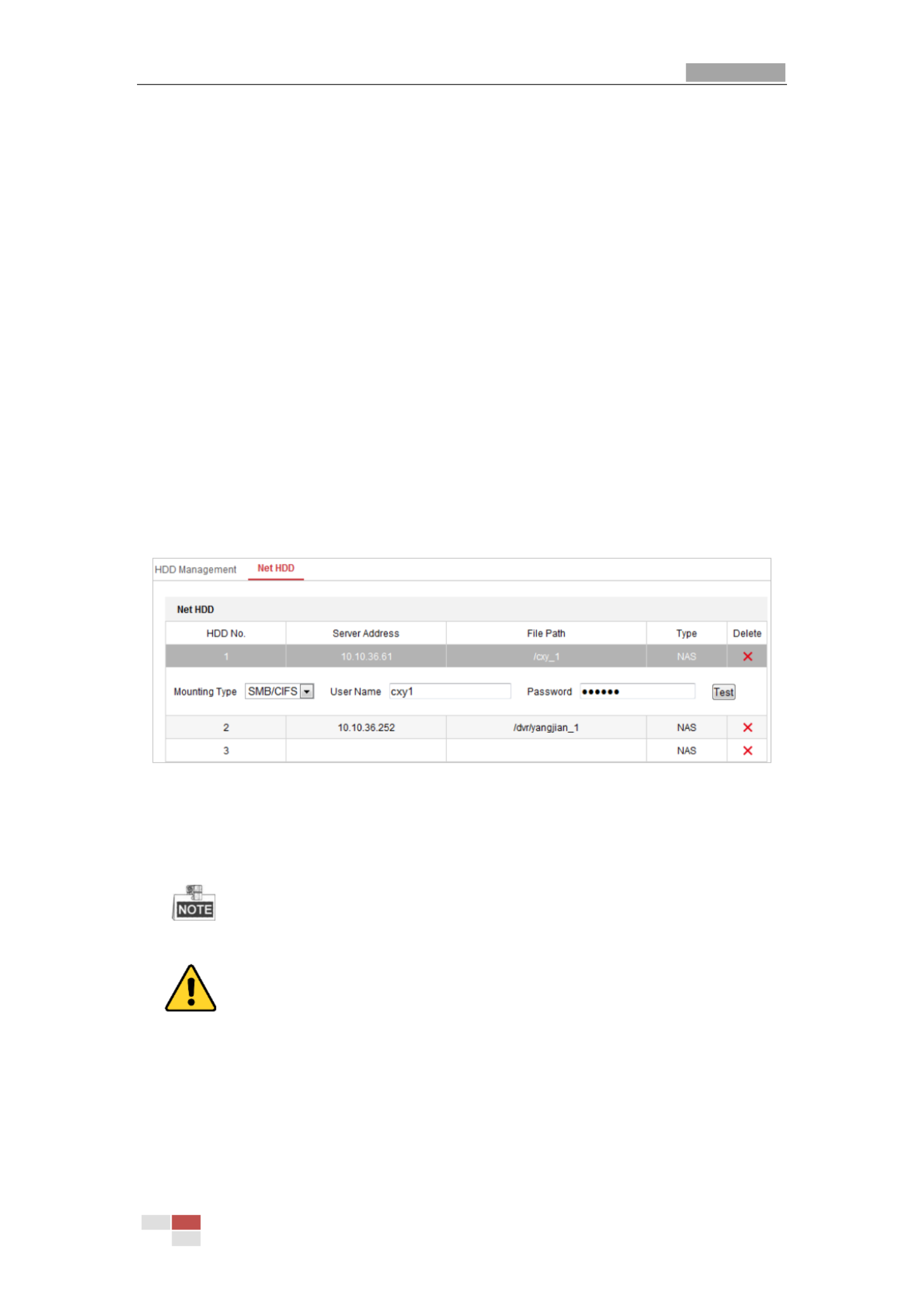
User Manual of Thermal Network Speed dome
© Hikvision
39
St
St
St
StSteps:
eps:
eps:
eps:eps:
1) Configure the FTP settings and check checkbox in FTP Settings
Upl
Upl
Upl
UplUplo
o
o
ooad
ad
ad
ad ad P
P
P
PPi
i
i
iict
ct
ct
ctcture
ure
ure
ureure
interface. Please refer to for more details
Sect
Sect
Sect
SectSecti
i
i
iion
on
on
on on 7.
7.
7.
7.7.1
1
1
11.
.
.
..2
2
2
2 2 Confi
Confi
Confi
ConfiConfigu
gu
gu
guguri
ri
ri
riring
ng
ng
ng ng FTP Se
FTP Se
FTP Se
FTP SeFTP Setti
tti
tti
ttittings
ngs
ngs
ngsngs
to configure FTP parameters.
2) Check checkbox in Motion Detection Settings or Alarm Input
Uplo
Uplo
Uplo
UploUpload to FTP
ad to FTP
ad to FTP
ad to FTPad to FTP
interface. Refer to Sect
Sect
Sect
SectSecti
i
i
iion
on
on
onon 5.
5.
5.
5. 5.2.
2.
2.
2.2.1 Conf
1 Conf
1 Conf
1 Conf1 Confi
i
i
iiguri
guri
guri
guriguring Mot
ng Mot
ng Mot
ng Motng Motio
io
io
ioion Det
n Det
n Det
n Detn Detecti
ecti
ecti
ectiection
on
on
onon.
3) Check the checkbox.
Enabl
Enabl
Enabl
EnablEnable
e
e
ee Event
Event
Event
Event Event-
-
-
--tri
tri
tri
tritrig
g
g
gggered S
gered S
gered S
gered Sgered Snapsh
napsh
napsh
napshnapshot
ot
ot
otot
5.
5.
5.
5.5.1.
1.
1.
1.1.3
3
3
33 Conf
Conf
Conf
ConfConfi
i
i
iig
g
g
ggur
ur
ur
ururi
i
i
iin
n
n
nng Net
g Net
g Net
g Netg Net
HDD
HDD
HDD
HDD HDD
Be
Be
Be
BeBefore yo
fore yo
fore yo
fore yofore you st
u st
u st
u stu start
art
art
artart:
:
:
::
The network disk should be available within the network and properly configured to store
the recorded files, log files, etc.
St
St
St
StSteps:
eps:
eps:
eps:eps:
Ad
Ad
Ad
AdAdd t
d t
d t
d td the ne
he ne
he ne
he nehe network
twork
twork
tworktwork di
di
di
di dis
s
s
ssk
k
k
kk
1. Enter the NAS (Network-Attached Storage) settings interface:
Conf
Conf
Conf
ConfConfi
i
i
iigurat
gurat
gurat
guratgurati
i
i
iion
on
on
on on >
>
>
>> Sto
Sto
Sto
StoStorage
rage
rage
ragerage > Sto
> Sto
> Sto
> Sto > Storage Ma
rage Ma
rage Ma
rage Marage Management
nagement
nagement
nagement nagement > Net HDD
> Net HDD
> Net HDD
> Net HDD > Net HDD
Figure 5-5 Select Net HDD Type
2. Enter the IP address and the file path of the network disk.
3. Select the mounting type. NFS and SMB/CIFS are selectable. You can set the user
name and password to guarantee the security if SMB/CIFS is selected.
Please refer to the NAS User Manual for creating the file path.
For your privacy and to better protect your system against security risks, we
strongly recommend the use of strong passwords for all functions and network
devices. The password should be something of your own choosing (using a
minimum of 8 characters, including upper case letters, lower case letters, numbers
and special characters) in order to increase the security of your product.
Proper configuration of all passwords and other security settings is the
responsibility of the installer and/or end-user.

User Manual of Thermal Network Speed dome
© Hikvision
40
4. Click to add the network disk.
After having saved successfully, you need to reboot the speed dome to activate the
settings.
Ini
Ini
Ini
IniIniti
ti
ti
titial
al
al
alali
i
i
iize t
ze t
ze t
ze tze the
he
he
he he added
added
added
added added net
net
net
netnetwork
work
work
workwork d
d
d
d di
i
i
iisk
sk
sk
sksk.
.
.
..
1. Enter the HDD settings interface (Confi
Confi
Confi
ConfiConfigur
gur
gur
gurgurat
at
at
atati
i
i
iion
on
on
on on >
>
>
> > Sto
Sto
Sto
StoStorage
rage
rage
ragerage
>
>
>
> > Storage
Storage
Storage
StorageStorage
Management
Management
Management
ManagementManagement
>
>
>
> >
HDD
HDD
HDD
HDD HDD Management
Management
Management
ManagementManagement), in which you can view the capacity, free space, status, type and
property of the disk.
Figure 5-6 Storage Management Interface
2. If the status of the disk is , check the corresponding checkbox to select the
Un
Un
Un
Un Unin
in
in
inini
i
i
iit
t
t
tti
i
i
iial
al
al
alali
i
i
iiz
z
z
zzed
ed
ed
eded
disk and click Format
Format
Format
FormatFormat to start initializing the disk.
3. When the initialization completed, the status of disk will become as shown in
Normal
Normal
Normal
NormalNormal
Figure 5-7
.
.
.
..
Figure 5-7 View Disk Status
Defi
Defi
Defi
DefiDefin
n
n
nne t
e t
e t
e te the Q
he Q
he Q
he Qhe Quot
uot
uot
uotuota f
a f
a f
a fa for Record an
or Record an
or Record an
or Record anor Record and Pi
d Pi
d Pi
d Pid Pictu
ctu
ctu
ctuctures
res
res
resres
1. Input the quota percentage for picture and for record.
2. Click and refresh the browser page to activate the settings.
Save
Save
Save
Save Save

User Manual of Thermal Network Speed dome
© Hikvision
41
Figure 5-8 Quota Settings
Up to 8 NAS disks can be connected to the speed dome.
To initialize and use the memory card after insert it to the speed dome, please refer to
the steps of NAS disk initialization
5.
5.
5.
5.5.2
2
2
22 B
B
B
BBa
a
a
aasi
si
si
sisic Even
c Even
c Even
c Evenc Event
t
t
tt Con
Con
Con
Con Conf
f
f
ffi
i
i
iigur
gur
gur
gurgurat
at
at
atati
i
i
iion
on
on
onon
Pu
Pu
Pu
PuPurpo
rpo
rpo
rporpose:
se:
se:
se:se:
This section explains how to configure the network speed dome to respond to alarm
events, including motion detection, video tampering alarm input, alarm output and
exception. These events can trigger the alarm actions, such as Send Email, Notify
Surveillance Center, etc.
For example, when motion detection is triggered, the network speed dome sends a
notification to an e-mail address.
On the event configuration page, click to show the PTZ control panel or click to
hide it.
Click the direction buttons to control the pan/tilt movements.
Click the zoom/iris/focus buttons to realize lens control.
The functions vary depending on the models of speed dome.
5.2.1 Conf
Conf
Conf
ConfConfi
i
i
iigu
gu
gu
guguri
ri
ri
ririn
n
n
nng M
g M
g M
g Mg Mot
ot
ot
ototi
i
i
iio
o
o
oon
n
n
n n Det
Det
Det
DetDetec
ec
ec
ecect
t
t
tti
i
i
iio
o
o
oon
n
n
nn
Pu
Pu
Pu
PuPurpo
rpo
rpo
rporpose:
se:
se:
se:se:
Motion detection is a feature which can trigger alarm actions and actions of recording
videos when the motion occurred in the surveillance scen e.
St
St
St
StSteps
eps
eps
epseps:
:
:
::
1. Enter the motion detection setting interface:
Conf
Conf
Conf
ConfConfi
i
i
iigura
gura
gura
guragurati
ti
ti
tition >
on >
on >
on > on > Event
Event
Event
EventEvent > B
> B
> B
> B > Basi
asi
asi
asiasic
c
c
cc Event
Event
Event
Event Event > Mot
> Mot
> Mot
> Mot > Moti
i
i
iion Det
on Det
on Det
on Deton Detecti
ecti
ecti
ectiection
on
on
onon
2. Select the channel to set the motion detection.
3. Check the checkbox of the to enable this function.
Enabl
Enabl
Enabl
Enabl Enable M
e M
e M
e Me Mot
ot
ot
ototi
i
i
iion De
on De
on De
on Deon Detect
tect
tect
tecttecti
i
i
iio
o
o
oon
n
n
nn
You can check the checkbox if you want the
Enab
Enab
Enab
EnabEnabl
l
l
lle
e
e
e e Dy
Dy
Dy
DyDynamic
namic
namic
namic namic Anal
Anal
Anal
AnalAnaly
y
y
yysi
si
si
sisis
s
s
ss
for
for
for
for for Mot
Mot
Mot
MotMoti
i
i
iion
on
on
onon
detected object get marked with rectangle in the live view.
4. Select the configuration mode as and set the corresponding motion
No
No
No
NoNormal
rmal
rmal
rmalrmal or Ex
Ex
Ex
ExExper
per
per
perpert
t
t
tt
detection parameters.
Normal
Normal
Normal
Normal Normal

User Manual of Thermal Network Speed dome
© Hikvision
42
Figure 5-9 Motion Detection Settings-Normal
St
St
St
StSteps:
eps:
eps:
eps:eps:
(1) Click and drag the mouse on the live video image to draw a motion
detection area.
(2) Click to finish drawing.
You can draw up to 8 motion detection areas on the same image.
You can click to clear all of the areas.
(3) Move the slider to set the
sensitivity of the detection.
Exper
Exper
Exper
ExperExpert
t
t
t t

User Manual of Thermal Network Speed dome
© Hikvision
43
Figure 5-10 Motion Detection Settings-Expert
Steps:
(1) Set the Sch
Sch
Sch
SchSchedul
edul
edul
eduledule
e
e
ee Image Sett
Image Sett
Image Sett
Image Sett Image Setti
i
i
iings
ngs
ngs
ngsngs, there are and
OFF
OFF
OFF
OFFOFF, A
A
A
AAuto
uto
uto
utouto-S
-S
-S
-S-Swit
wit
wit
witwitch
ch
ch
ch ch
Sch
Sch
Sch
SchSchedul
edul
edul
eduleduled
ed
ed
eded-Swi
-Swi
-Swi
-Swi-Switc
tc
tc
tctch
h
h
hh selectable. If the schedule image switch mode is enabled, you
can configure the detection rule for the day and night separately.
OFF
OFF
OFF
OFFOFF:
:
:
::
Disable the day and night switch.
Au
Au
Au
AuAuto
to
to
toto-S
-S
-S
-S-Sw
w
w
wwi
i
i
iit
t
t
ttch:
ch:
ch:
ch:ch:
Switch the day and night mode according to the illumination
automatically.
Sch
Sch
Sch
SchSchedul
edul
edul
eduleduled
ed
ed
eded-Swi
-Swi
-Swi
-Swi-Switc
tc
tc
tctch:
h:
h:
h:h:
Switch to the day mode at 6:00 a.m., and switch to the night
mode at 18:00 p.m..
(2) Select to configure in the dropdown list. Area No.
Area No.
Area No.
Area No.Area No.
(3) Set the values of sensitivity and proportion of object on area.
Sen
Sen
Sen
SenSensi
si
si
sisiti
ti
ti
titiv
v
v
vvi
i
i
iity
ty
ty
tyty:
:
:
::
The greater the value is, the easier the alarm will be triggered.
Pro
Pro
Pro
ProPropor
por
por
porporti
ti
ti
tition of
on of
on of
on ofon of O
O
O
O Obje
bje
bje
bjebject o
ct o
ct o
ct oct on Area
n Area
n Area
n Arean Area:
:
:
::
When the size proportion of the moving object
exceeds the predefined value, the alarm will be triggered. The less the value is,
the easier the alarm will be triggered.
5. Set the A
A
A
AArmin
rmin
rmin
rminrming Sche
g Sche
g Sche
g Scheg Schedul
dul
dul
duldule
e
e
ee for Motion Detection.
(1) Click tab to enter the arming schedule setting interface.

User Manual of Thermal Network Speed dome
© Hikvision
44
Figure 5-11 Arming Schedule
(2) Select the timeline of a certain day, click and drag the mouse to set the arming
schedule (the start time and end time of the arming task).
(3) After you set the scheduled task, you can click and copy the task to other
days (optional).
Figure 5-12 Arming Time Schedule
(4) After setting the arming schedule, you can click a segment to display the
segment arming settings interface to edit the segment record parameters
(optional).
Figure 5-13 Segment Arming Settings
(5) Click to save the settings.
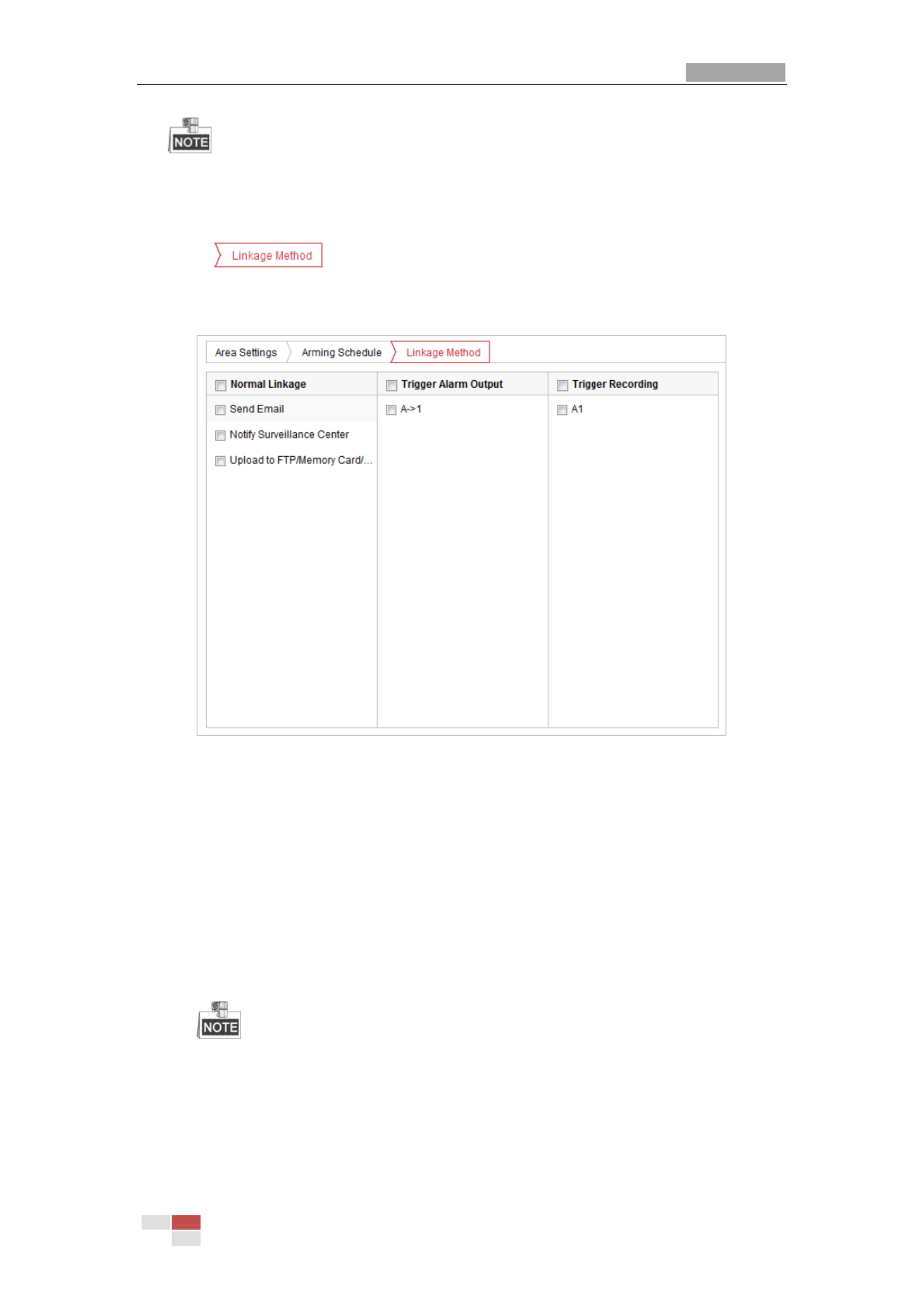
User Manual of Thermal Network Speed dome
© Hikvision
45
The time of each period cannot be overlapped. Up to 8 periods can be configured for
each day.
6. Set the Al
Al
Al
AlAlarm Act
arm Act
arm Act
arm Actarm Actio
io
io
ioions
ns
ns
nsns for Motion Detection.
Click tab to enter the interface.
Lin
Lin
Lin
LinLink
k
k
kkage Me
age Me
age Me
age Meage Method
thod
thod
thodthod
You can specify the linkage method when an event occurs. The following contents are
about how to configure the different types of linkage method.
Figure 5-14 Linkage Method
Check the checkbox to select the linkage method. Notify Surveillance Center,
Send Email, Upload to FTP/Memory/NAS, Trigger Alarm Output and Trigger
Recording are selectable.
Noti
Noti
Noti
NotiNotif
f
f
ffy
y
y
yy Surv
Surv
Surv
Surv Survei
ei
ei
eieil
l
l
lll
l
l
llance
ance
ance
anceance Cente
Cente
Cente
Cente Center
r
r
r r
Send an exception or alarm signal to remote management software when an
event occurs.
Send
Send
Send
SendSend Ema
Ema
Ema
Ema Emai
i
i
iil
l
l
ll
Send an email with alarm information to a user or users when an event occurs.
To send the Email when an event occurs, you need to refer to Se
Se
Se
SeSecti
cti
cti
ctictio
o
o
oon
n
n
nn Confi
Confi
Confi
ConfiConfigur
gur
gur
gurguri
i
i
iing
ng
ng
ng ng
Email
Email
Email
EmailEmail S
S
S
S Sett
ett
ett
ettetti
i
i
iings
ngs
ngs
ngsngs
to set the Email parameters.
Upl
Upl
Upl
UplUpload
oad
oad
oad oad to
to
to
toto FTP/M
FTP/M
FTP/M
FTP/M FTP/Memory/NA
emory/NA
emory/NA
emory/NAemory/NAS
S
S
S S
Capture the image when an alarm is triggered and upload the picture to a FTP
server.

User Manual of Thermal Network Speed dome
© Hikvision
46
You need a FTP server and set FTP parameters first. Refer to Sect
Sect
Sect
SectSecti
i
i
iion
on
on
on on Conf
Conf
Conf
ConfConfi
i
i
iiguri
guri
guri
guriguring
ng
ng
ng ng
FTP Se
FTP Se
FTP Se
FTP SeFTP Sett
tt
tt
tttti
i
i
iings
ngs
ngs
ngsngs
for setting FTP parameters.
T
T
T
TTri
ri
ri
ririgge
gge
gge
ggegger A
r A
r A
r Ar Ala
la
la
lalarm Outpu
rm Outpu
rm Outpu
rm Outpurm Output
t
t
t t
Trigger one or more external alarm outputs when an event occurs.
To trigger an alarm output when an event occurs, please refer to Secti
Secti
Secti
SectiSection
on
on
on on 5.
5.
5.
5.5.2.
2.
2.
2.2.4
4
4
4 4
Conf
Conf
Conf
ConfConfi
i
i
iiguri
guri
guri
gurigurin
n
n
nng A
g A
g A
g Ag Ala
la
la
lalarm Outpu
rm Outpu
rm Outpu
rm Outpurm Output
t
t
tt to set the alarm output parameters.
T
T
T
TTri
ri
ri
ririgge
gge
gge
ggegger Recordi
r Recordi
r Recordi
r Recordir Recording
ng
ng
ng ng
Record a video when an event occurs.
You have to set the recording schedule to realize this function. Please refer to
Sec
Sec
Sec
SecSecti
ti
ti
tition
on
on
on on 5.
5.
5.
5.5.1.
1.
1.
1.1.1
1
1
11
Conf
Conf
Conf
ConfConfig
ig
ig
igiguri
uri
uri
uriuring
ng
ng
ngng
Recordi
Recordi
Recordi
RecordiRecording
ng
ng
ng ng Sche
Sche
Sche
ScheSchedul
dul
dul
duldule
e
e
ee
for settings the recording
schedule.
5.
5.
5.
5.5.2
2
2
22.
.
.
..2
2
2
22 C
C
C
CCon
on
on
ononfi
fi
fi
fifigu
gu
gu
guguri
ri
ri
riring
ng
ng
ngng
V
V
V
VVi
i
i
iid
d
d
ddeo
eo
eo
eoeo T
T
T
T Tamp
amp
amp
ampamp i
i
i
iing
ng
ng
ngng A
A
A
A Al
l
l
lla
a
a
aarm
rm
rm
rm rm er
er
er
erer
Pu
Pu
Pu
PuPurpose
rpose
rpose
rposerpose:
:
:
::
You can configure the speed dome to trigger the alarm actions when the lens is covered.
St
St
St
StSteps:
eps:
eps:
eps:eps:
1. Enter the Video Tampering settings interface :
Conf
Conf
Conf
ConfConfi
i
i
iigurat
gurat
gurat
guratgurati
i
i
iion
on
on
on on > Event
> Event
> Event
> Event> Event > Bas
> Bas
> Bas
> Bas > Basi
i
i
iic Event
c Event
c Event
c Eventc Event >
>
>
> > V
V
V
VVid
id
id
idideo T
eo T
eo T
eo Teo Tamperi
amperi
amperi
amperiampering
ng
ng
ngng
2. Select the channel to set the video tampering alarm.

User Manual of Thermal Network Speed dome
© Hikvision
47
Figure 5-15 Tampering Alarm
3. Check checkbox to enable the tampering detection.
Enabl
Enabl
Enabl
EnablEnable
e
e
e e
4. Click tab to enter the arming schedule setting interface. The
arming schedule configuration is the same as the setting of the arming schedule for
motion detection. Refer to .
Secti
Secti
Secti
SectiSection
on
on
onon 5.
5.
5.
5.5.2.
2.
2.
2.2.1
1
1
11 Confi
Confi
Confi
Confi Config
g
g
gguri
uri
uri
uriuring
ng
ng
ngng Mo
Mo
Mo
Mo Moti
ti
ti
tition
on
on
onon Dete
Dete
Dete
Dete Detect
ct
ct
ctctio
io
io
ioion
n
n
nn
5. Click tab to select the linkage method taken for tampering, notify
surveillance center, send email and trigger alarm output are selectable. Refer to
S
S
S
SSecti
ecti
ecti
ectiectio
o
o
oon
n
n
nn
5.
5.
5.
5.5.2.
2.
2.
2.2.1 Conf
1 Conf
1 Conf
1 Conf1 Confi
i
i
iigu
gu
gu
guguri
ri
ri
riring M
ng M
ng M
ng Mng Mot
ot
ot
ototi
i
i
iion Det
on Det
on Det
on Deton Detec
ec
ec
ececti
ti
ti
tition
on
on
onon.
6. Click to save the settings.
5.
5.
5.
5.5.2
2
2
22.
.
.
..3
3
3
33 Conf
Conf
Conf
ConfConfi
i
i
iigu
gu
gu
guguri
ri
ri
riring
ng
ng
ngng A
A
A
A Al
l
l
llarm I
arm I
arm I
arm Iarm In
n
n
nnpu
pu
pu
puput
t
t
tt
St
St
St
StSteps
eps
eps
epseps:
:
:
::
1. Enter the Alarm Input settings interface:
Conf
Conf
Conf
ConfConfi
i
i
iigurat
gurat
gurat
guratgurati
i
i
iion > Event
on > Event
on > Event
on > Eventon > Event >
>
>
> > Ba
Ba
Ba
BaBasi
si
si
sisic Eve
c Eve
c Eve
c Evec Event
nt
nt
nt nt > A
> A
> A
> A> Al
l
l
llarm
arm
arm
armarm Inpu
Inpu
Inpu
InpuInput
t
t
tt
2. Choose the alarm input No. and the Alarm Type. The alarm type can be NO (Normally
Open) and NC (Normally Closed).
3. Edit the name in to set a name for the
alarm input (optional).

User Manual of Thermal Network Speed dome
© Hikvision
48
Figure 5-16 Alarm Input Settings
4. Click tab to enter the arming schedule setting interface. The
arming schedule configuration is the same as the setting of the arming schedule for
motion detection. Refer to
Secti
Secti
Secti
SectiSection
on
on
onon 5.
5.
5.
5.5.2.
2.
2.
2.2.1
1
1
11 Confi
Confi
Confi
Confi Config
g
g
gguri
uri
uri
uriuring
ng
ng
ngng Mot
Mot
Mot
Mot Moti
i
i
iion De
on De
on De
on Deon Detect
tect
tect
tecttecti
i
i
iion
on
on
onon .
5. Click tab to select the linkage method taken for alarm input, including
Notify Surveillance Center, Send Email, Upload to FTP/Memory Card/NAS, Trigger
Alarm Output and Trigger Recording. Refer to Sect
Sect
Sect
SectSecti
i
i
iion
on
on
onon 5.
5.
5.
5.5.2.
2.
2.
2.2.1
1
1
11
Confi
Confi
Confi
ConfiConfiguri
guri
guri
gurigurin
n
n
nng
g
g
g g Mot
Mot
Mot
MotMoti
i
i
iion
on
on
on on
Dete
Dete
Dete
DeteDetecti
cti
cti
ctiction
on
on
onon.
6. You can also choose the PTZ linking for the alarm input. Check the relative checkbox
and select the No. to enable Preset Calling, Patrol Calling or Pattern Calling.
7. You can copy your settings to other alarm inputs.
8. Click to save the settings.
Figure 5-17 Linkage Method

User Manual of Thermal Network Speed dome
© Hikvision
49
5.
5.
5.
5.5.2.
2.
2.
2.2.4
4
4
44 Conf
Conf
Conf
ConfConfi
i
i
iigu
gu
gu
guguri
ri
ri
riring
ng
ng
ngng A
A
A
A Al
l
l
llar
ar
ar
ararm Ou
m Ou
m Ou
m Oum Out
t
t
ttp
p
p
pput
ut
ut
utut
St
St
St
StSteps
eps
eps
epseps:
:
:
::
1. Enter the Alarm Output settings interface:
Conf
Conf
Conf
ConfConfi
i
i
iigurat
gurat
gurat
guratgurati
i
i
iion
on
on
onon> Event
> Event
> Event
> Event> Event > B
> B
> B
> B > Basi
asi
asi
asiasic Even
c Even
c Even
c Evenc Event >
t >
t >
t > t > Al
Al
Al
AlAla
a
a
aarm O
rm O
rm O
rm Orm Out
ut
ut
ututput
put
put
putput
2. Select one alarm output channel in the
A
A
A
AAl
l
l
llarm Out
arm Out
arm Out
arm Outarm Output
put
put
putput dropdown list.
3. Set a name in for the alarm output
(optional).
4. The time can be set to
Delay
Delay
Delay
DelayDelay 5sec
5sec
5sec
5sec5sec, 1
1
1
110s
0s
0s
0s0sec
ec
ec
ecec, 30s
30s
30s
30s30sec
ec
ec
ecec, 1min
1min
1min
1min1min, 2mi
2mi
2mi
2mi2min
n
n
nn, 5min
5min
5min
5min5min,
,
,
,, 10mi
10mi
10mi
10mi 10min
n
n
nn or Manual
Manual
Manual
Manual Manual.
The delay time refers to the time duration that the alarm output remains in effect after
alarm occurs.
5. Click tab to enter the arming schedule setting interface. The time
schedule configuration is the same as the settings of the arming schedule for motion
detection. Refer to .
S
S
S
S Sect
ect
ect
ectecti
i
i
iion
on
on
onon 5.
5.
5.
5.5.2
2
2
22.
.
.
..1
1
1
11 Confi
Confi
Confi
Confi Configur
gur
gur
gurgurin
in
in
ining Mo
g Mo
g Mo
g Mog Moti
ti
ti
titio
o
o
oon Det
n Det
n Det
n Detn Detecti
ecti
ecti
ectiection
on
on
onon
Figure 5-18 Alarm Output Settings
6. You can copy the settings to other alarm outputs.
7. Click to save the settings.

User Manual of Thermal Network Speed dome
© Hikvision
50
5.
5.
5.
5.5.2.
2.
2.
2.2.5
5
5
55 Hand
Hand
Hand
HandHandl
l
l
lli
i
i
iin
n
n
nng Ex
g Ex
g Ex
g Exg Excep
cep
cep
cepcept
t
t
tti
i
i
iio
o
o
oon
n
n
nn
The exception type can be HDD full, HDD error, network disconnected, IP address
conflicted and illegal login to the speed domes.
St
St
St
StSteps
eps
eps
epseps:
:
:
::
1. Enter the Exception settings interface:
Conf
Conf
Conf
ConfConfi
i
i
iigurat
gurat
gurat
guratgurati
i
i
iion
on
on
onon >
>
>
> > Event
Event
Event
EventEvent > Ba
> Ba
> Ba
> Ba > Basi
si
si
sisic Eve
c Eve
c Eve
c Evec Event
nt
nt
nt nt > Except
> Except
> Except
> Except> Excepti
i
i
iion
on
on
onon
2. Check the checkbox to set the actions taken for the Exception alarm. Refer to S
S
S
SSect
ect
ect
ectecti
i
i
iion
on
on
onon
5.
5.
5.
5.5.2.
2.
2.
2.2.1 Conf
1 Conf
1 Conf
1 Conf1 Confi
i
i
iigu
gu
gu
guguri
ri
ri
riring M
ng M
ng M
ng Mng Mot
ot
ot
ototi
i
i
iion Det
on Det
on Det
on Deton Detec
ec
ec
ececti
ti
ti
tition
on
on
onon.
Figure 5-19 Exception Settings
3. Click to save the settings.
5.
5.
5.
5.5.3
3
3
33 Smar
Smar
Smar
SmarSmart
t
t
tt Eve
Eve
Eve
Eve Event
nt
nt
ntnt
Con
Con
Con
ConConf
f
f
ffi
i
i
iig
g
g
ggu
u
u
uura
ra
ra
rarat
t
t
tti
i
i
iio
o
o
oon
n
n
nn
The functions vary depending on the models of speed dome.

User Manual of Thermal Network Speed dome
© Hikvision
51
5.3.1 Det
Det
Det
DetDetect
ect
ect
ectecti
i
i
iin
n
n
nng
g
g
g g Au
Au
Au
AuAudi
di
di
didio
o
o
oo E
E
E
E Excep
xcep
xcep
xcepxcepti
ti
ti
tition
on
on
onon
Pu
Pu
Pu
PuPurpose:
rpose:
rpose:
rpose:rpose:
When you enable this function and audio exception occurs, the alarm actions will be
triggered.
St
St
St
StSteps:
eps:
eps:
eps:eps:
1. Enter the video audio exception detection interface:
Conf
Conf
Conf
ConfConfigu
igu
igu
iguigurati
rati
rati
ratiration
on
on
onon > Event
> Event
> Event
> Event > Event > Smart
> Smart
> Smart
> Smart > Smart Event >
Event >
Event >
Event > Event > A
A
A
A Audi
udi
udi
udiudio Except
o Except
o Except
o Excepto Excepti
i
i
iion
on
on
onon Detect
Detect
Detect
Detect Detectio
io
io
ioion
n
n
nn
Figure 5-20 Audio Exception Detection
2. Check the checkbox of to enable the audio input exception
Audi
Audi
Audi
Audi Audio Loss
o Loss
o Loss
o Loss o Loss Detec
Detec
Detec
DetecDetecti
ti
ti
tition
on
on
on on
detection.
3. Check the checkbox of checkbox to
Su
Su
Su
SuSudden
dden
dden
dden dden Incre
Incre
Incre
IncreIncrease
ase
ase
ase ase o
o
o
oof
f
f
f f Sound
Sound
Sound
Sound Sound Int
Int
Int
IntIntens
ens
ens
ensensit
it
it
itity
y
y
yy
Dete
Dete
Dete
DeteDetecti
cti
cti
ctiction
on
on
onon
enable the sudden rise detection.
Sensi
Sensi
Sensi
SensiSensiti
ti
ti
titiv
v
v
vvit
it
it
itity
y
y
yy: Range [1-100], the smaller the value the more severe the sound change
will trigger the detection.
Soun
Soun
Soun
SounSound
d
d
dd I
I
I
IInten
nten
nten
ntenntensi
si
si
sisity
ty
ty
tyty Thresho
Thresho
Thresho
ThreshoThreshold
ld
ld
ldld : Range [1-100], it can filter the sound in the environment,
the louder the environment sound, the higher the value should be. You can adjust it
according to the actual environment.
4. Check the checkbox of checkbox to
Sudden
Sudden
Sudden
SuddenSudden
Decreas
Decreas
Decreas
DecreasDecrease
e
e
e e o
o
o
oof
f
f
f f Sound
Sound
Sound
Sound Sound I
I
I
IInten
nten
nten
ntenntensi
si
si
sisity
ty
ty
ty ty Det
Det
Det
DetDetecti
ecti
ecti
ectiection
on
on
on on
enable the sudden drop detection.
Sen
Sen
Sen
SenSensi
si
si
sisiti
ti
ti
titivi
vi
vi
vivit
t
t
tty
y
y
yy: Range [1-100], the smaller the value the more severe the sound change
will trigger the detection.

User Manual of Thermal Network Speed dome
© Hikvision
52
5. Click tab to enter the arming schedule setting interface. The time
schedule configuration is the same as the settings of the arming schedule for motion
detection. Refer to .
Sect
Sect
Sect
SectSectio
io
io
ioion
n
n
nn 5.
5.
5.
5.5.2.
2.
2.
2.2.1
1
1
11 Confi
Confi
Confi
Confi Configuri
guri
guri
guriguring Mo
ng Mo
ng Mo
ng Mong Moti
ti
ti
tition Det
on Det
on Det
on Deton Detecti
ecti
ecti
ectiection
on
on
onon
6. Click tab to select the linkage method taken for the audio input
exception, Notify Surveillance Center, Send Email, Trigger Alarm Output and Trigger
Recording are selectable. Refer to Secti
Secti
Secti
SectiSection
on
on
onon 5.
5.
5.
5.5.2.
2.
2.
2.2.1
1
1
1 1 C
C
C
CConf
onf
onf
onfonfigu
igu
igu
iguigurin
rin
rin
rinring Mot
g Mot
g Mot
g Motg Motion
ion
ion
ionion Detect
Detect
Detect
Detect Detection
ion
ion
ionion .
7. Click to save the settings.
5.3.2 Conf
Conf
Conf
ConfConfi
i
i
iigur
gur
gur
gurguri
i
i
iing
ng
ng
ngng Fi
Fi
Fi
Fi Fire
re
re
re re and
and
and
andand Smok
Smok
Smok
Smok Smoke
e
e
e e Dete
Dete
Dete
DeteDetecti
cti
cti
ctiction
on
on
onon
Pu
Pu
Pu
PuPurpose:
rpose:
rpose:
rpose:rpose:
When you enable this function and fire source or smoke is detected, the alarm actions will
be triggered. You can set different detection mode, fire source zoom mode, and so on.
St
St
St
StSteps:
eps:
eps:
eps:eps:
1. Enter Confi
Confi
Confi
ConfiConfigur
gur
gur
gurgurati
ati
ati
atiation>Ad
on>Ad
on>Ad
on>Adon>Advanced
vanced
vanced
vanced vanced Confi
Confi
Confi
ConfiConfigurat
gurat
gurat
guratgurati
i
i
iion>Syst
on>Syst
on>Syst
on>Syston>System>VCA
em>VCA
em>VCA
em>VCA em>VCA Resource
Resource
Resource
Resource Resource T
T
T
TTy
y
y
yype
pe
pe
pepe to select
Fi
Fi
Fi
FiFire and Smok
re and Smok
re and Smok
re and Smokre and Smoke Detec
e Detec
e Detec
e Detece Detecti
ti
ti
tition
on
on
onon as VCA Resource Type.
2. Enter the fire and smoke detection interface:
Conf
Conf
Conf
ConfConfigu
igu
igu
iguigurati
rati
rati
ratiration >
on >
on >
on > on > E
E
E
EEven
ven
ven
venvent > Smart
t > Smart
t > Smart
t > Smartt > Smart Event
Event
Event
Event Event > D
> D
> D
> D> Dyn
yn
yn
ynynam
am
am
amamic
ic
ic
icic Fi
Fi
Fi
Fi Fir
r
r
rre
e
e
e e and Smoke
and Smoke
and Smoke
and Smokeand Smoke Detec
Detec
Detec
Detec Detecti
ti
ti
tition
on
on
onon
Figure 5-21 Fire and Smoke Detection
3. Check the checkbox of to enable the fire and smoke
Enabl
Enabl
Enabl
EnablEnable Fi
e Fi
e Fi
e Fie Fire
re
re
re re and Smok
and Smok
and Smok
and Smokand Smoke Det
e Det
e Det
e Dete Detecti
ecti
ecti
ectiection
on
on
on on
detection function.

User Manual of Thermal Network Speed dome
© Hikvision
53
The function of dynamic fire source detection can only be enabled for
camera 2.
Fi
Fi
Fi
FiFire and
re and
re and
re and re and Sm
Sm
Sm
SmSmoke
oke
oke
oke oke Detecti
Detecti
Detecti
DetectiDetectio
o
o
oon Mode:
n Mode:
n Mode:
n Mode:n Mode:
1) Select Fire or Smoke, and the system alarms when device is either triggered
by Fire Source Detection or Smoke Detection.
2) Select Fire and Smoke, the system holds when device is triggered by Fire
Source Detection or Smoke Detection. When target is detected by both
rules, the system sends two alarms, otherwise, the system sends single
alarm.
3) Select Double Confirm, the system alarms when device is both triggered by
Fire Source Detection and Smoke Detection.
4) Select Specified Fire Source, and the system alarms when device is triggered
by fire source detection.
5) Select Specified Smoke, and the system alarms when device is triggered by
smoke.
Dete
Dete
Dete
DeteDetecti
cti
cti
ctiction Mode:
on Mode:
on Mode:
on Mode:on Mode: Select detection mode as by Multiple Frame, and the system
alarms with high accuracy. Select detection mode as by Single Frame, and the
system alarms with short delay.
Fi
Fi
Fi
FiFire
re
re
re re Source
Source
Source
Source Source Zoom
Zoom
Zoom
Zoom Zoom Mode:
Mode:
Mode:
Mode:Mode: In Auto mode, the system moves and locates at the fire
source, and then it zooms according to the predefined focus mode. To set the focus
mode, go to Configuration>Advanced Configuration>Image>Channel No.2>Focus
Mode.
Sen
Sen
Sen
SenSensi
si
si
sisiti
ti
ti
titivi
vi
vi
vivity
ty
ty
tyty:
:
:
:: Range [1-100], the smaller the value is, the fire source of lower
temperature can be detected.
Dwell
Dwell
Dwell
DwellDwell
T
T
T
TTime(
ime(
ime(
ime(ime(s):
s):
s):
s):s): Range [0-120]. You can set the dwell time of the speed dome
staying the position where detects the fire source when performing auto scan,
patrol, pattern, scheduled task, and park action.
Fi
Fi
Fi
FiFire
re
re
re re Sou
Sou
Sou
SouSour
r
r
rrce
ce
ce
ce ce Z
Z
Z
ZZoom
oom
oom
oom oom R
R
R
RRati
ati
ati
atiatio:
o:
o:
o:o: Set the zoom ratio of the optical channel when it detects
the fire source. In Auto mode, the optical channel changes its zoom ratio until two
channels have the same field of view. In Manual mode, you can set the optical
zoom ratio.
Smoke
Smoke
Smoke
Smoke Smoke Dete
Dete
Dete
DeteDetecti
cti
cti
ctiction:
on:
on:
on:on:
Set the sensitivity of the smoke detection. The greater the value
is, the easier the alarm will be triggered. (reserved)
4. Check the checkbox of Di
Di
Di
DiDisp
sp
sp
spsplay
lay
lay
laylay
Fi
Fi
Fi
FiFire
re
re
re re S
S
S
SSource
ource
ource
ource ource Fram
Fram
Fram
FramFrame
e
e
e e o
o
o
oon
n
n
n n S
S
S
SStream
tream
tream
treamtream to display a red frame
around the fire source on stream when fire occurs. (Optional)
5. Check the checkbox to select the linkage method taken for the alarm input. Refer to
Step 3 in Section 5.2 Configuring Motion Detection.1 . In the field of , you
O
O
O
OOther
ther
ther
ther ther Lin
Lin
Lin
LinLinkage
kage
kage
kagekage
can check the checkbox to enable the alarm output (The alarm output number varies
depending on device ability).
6. Click to save the settings.

User Manual of Thermal Network Speed dome
© Hikvision
54
5.
5.
5.
5.5.3.
3.
3.
3.3.3
3
3
33 Conf
Conf
Conf
ConfConfi
i
i
iigu
gu
gu
guguri
ri
ri
riring
ng
ng
ngng
Fi
Fi
Fi
FiFire S
re S
re S
re Sre So
o
o
oourc
urc
urc
urcurce Det
e Det
e Det
e Dete Detect
ect
ect
ectecti
i
i
iion
on
on
onon S
S
S
S Shi
hi
hi
hihiel
el
el
eleld
d
d
dd
Pu
Pu
Pu
PuPurpose
rpose
rpose
rposerpose:
:
:
::
Fire Source Shield enables you to shield certain areas from being detected in fire source
detection.
The privacy mask function is supported by the optical lens only.
St
St
St
StSteps
eps
eps
epseps:
:
:
::
1. Enter the Fire Source Detection Shield Setting interface:
Conf
Conf
Conf
ConfConfi
i
i
iigurat
gurat
gurat
guratgurati
i
i
iion
on
on
onon
Event
Event
Event
EventEvent
Smar
Smar
Smar
Smar Smart Even
t Even
t Even
t Event Event
t
t
t t
Fi
Fi
Fi
FiFire So
re So
re So
re Sore Source Det
urce Det
urce Det
urce Deturce Detect
ect
ect
ectecti
i
i
iion
on
on
on on Shi
Shi
Shi
ShiShie
e
e
eeld
ld
ld
ldld> > >
Figure 5-22 Fire Source Detection Shield
2. Click the PTZ control buttons to find the area you want to shield from the smoke
detection.
3. Click and drag the mouse in the live video window to draw the area.
Draw Area
Draw Area
Draw Area
Draw AreaDraw Area
4. You can drag the corners of the red rectangle area to change its shape and size.
5. Click to finish drawing or click to clear all of the areas you set
S
S
S
SSto
to
to
totop
p
p
p p Drawi
Drawi
Drawi
DrawiDrawing
ng
ng
ngng Cl
Cl
Cl
ClClea
ea
ea
eaear
r
r
r r Al
Al
Al
AlAll
l
l
ll
without saving them.
6. Set the value of Act
Act
Act
ActActi
i
i
iiv
v
v
vve
e
e
e e Z
Z
Z
ZZoom
oom
oom
oom oom R
R
R
RRati
ati
ati
atiatio
o
o
oo on your demand, and then the shield will only
appear when the zoom ratio is greater than the predefined value.
User Manual of Thermal Network Speed dome
© Hikvision
55
7. Click to save the smoke detection shield, and it will be listed in the
Ad
Ad
Ad
AdAdd
d
d
dd Fi
Fi
Fi
FiFire
re
re
re re Sou
Sou
Sou
SouSource
rce
rce
rce rce
Dete
Dete
Dete
DeteDetecti
cti
cti
ctiction
on
on
on on S
S
S
SShi
hi
hi
hihiel
el
el
eleld
d
d
d d Li
Li
Li
LiList
st
st
stst Del
Del
Del
DelDele
e
e
eete
te
te
tete area; you can select a region and click to delete it from
the list; you can also define the color of the regions.
8. Check the checkbox of to enable this function.
Enab
Enab
Enab
EnabEnabl
l
l
lle Fir
e Fir
e Fir
e Fire Fire Sou
e Sou
e Sou
e Soue Source Det
rce Det
rce Det
rce Detrce Detecti
ecti
ecti
ectiection
on
on
onon Shi
Shi
Shi
Shi Shiel
el
el
eleld
d
d
dd
You are allowed to draw up to 24 areas on the same image.
9. Click to save the settings.
For some models, the smoke detection function is not supported and
cannot select Fire and Smoke Detection Mode.
5.
5.
5.
5.5.3
3
3
33.
.
.
..4
4
4
44 Conf
Conf
Conf
ConfConfi
i
i
iig
g
g
gguri
uri
uri
uriuring
ng
ng
ngng S
S
S
S Smok
mok
mok
mokmoke Det
e Det
e Det
e Dete Detec
ec
ec
ececti
ti
ti
tition
on
on
onon S
S
S
S Shi
hi
hi
hihie
e
e
eel
l
l
lld
d
d
dd
Pu
Pu
Pu
PuPurpose
rpose
rpose
rposerpose:
:
:
::
Smoke Detection Shield enables you to shield certain areas from being detected in smoke
detection.
The privacy mask function is supported by the optical lens only.
The smoke detection shield function is only supported for some models.
St
St
St
StSteps:
eps:
eps:
eps:eps:
1. Enter the Smoke Detection Shield Setting interface:
Conf
Conf
Conf
ConfConfi
i
i
iigurat
gurat
gurat
guratgurati
i
i
iion
on
on
on on Event
Event
Event
EventEvent Smart Even
Smart Even
Smart Even
Smart Even Smart Event
t
t
t t
Smoke Det
Smoke Det
Smoke Det
Smoke DetSmoke Detecti
ecti
ecti
ectiection
on
on
onon Shi
Shi
Shi
Shi Shiel
el
el
eleld
d
d
dd> > >

User Manual of Thermal Network Speed dome
© Hikvision
56
Figure 5-23 Smoke Detection Shield
2. Click the PTZ control buttons to find the area you want to shield from the smoke
detection.
3. Click and drag the mouse in the live video window to draw the area.
Draw Area
Draw Area
Draw Area
Draw AreaDraw Area
4. You can drag the corners of the red rectangle area to change its shape and size.
5. Click to finish drawing or click to clear all of the areas you set
St
St
St
StStop
op
op
opop
Drawing
Drawing
Drawing
DrawingDrawing Cle
Cle
Cle
CleClear
ar
ar
ar ar A
A
A
AAl
l
l
lll
l
l
ll
without saving them.
6. Set the value of Ac
Ac
Ac
AcActi
ti
ti
titiv
v
v
vve
e
e
e e Zoom
Zoom
Zoom
Zoom Zoom R
R
R
RRat
at
at
atati
i
i
iio
o
o
oo on your demand, and then the shield will only
appear when the zoom ratio is greater than the predefined value.
7. Click to save the smoke detection shield, and it will be listed in the
Ad
Ad
Ad
AdAdd
d
d
dd S
S
S
SSmoke
moke
moke
moke moke
Dete
Dete
Dete
DeteDetecti
cti
cti
ctiction
on
on
onon
Shi
Shi
Shi
ShiShiel
el
el
eleld
d
d
d d Li
Li
Li
LiList
st
st
stst Del
Del
Del
DelDelete
ete
ete
eteete area; you can select a region and click to delete it from
the list; you can also define the color of the regions.
8. Check the checkbox of to enable this function.
Enabl
Enabl
Enabl
EnablEnable Smok
e Smok
e Smok
e Smoke Smoke Dete
e Dete
e Dete
e Detee Detecti
cti
cti
ctictio
o
o
oon Shi
n Shi
n Shi
n Shin Shiel
el
el
eleld
d
d
dd
You are allowed to draw up to 24 areas on the same image.
9. Click to save the settings.

User Manual of Thermal Network Speed dome
© Hikvision
57
5.3.5 Sh
Sh
Sh
ShShi
i
i
iip
p
p
pp Det
Det
Det
Det Detect
ect
ect
ectecti
i
i
iion
on
on
onon
Pu
Pu
Pu
PuPurpose
rpose
rpose
rposerpose:
:
:
::
When you enable this function and ship is detected, the alarm actions will be triggered.
St
St
St
StSteps:
eps:
eps:
eps:eps:
1. Enter Configuration>Advanced Configuration>System>VCA Resource Type to select
Shi
Shi
Shi
ShiShip
p
p
p p Detect
Detect
Detect
DetectDetecti
i
i
iion
on
on
onon as VCA Resource Type.
2. Enter the ship detection interface:
Conf
Conf
Conf
ConfConfi
i
i
iigurat
gurat
gurat
guratgurati
i
i
iion > A
on > A
on > A
on > Aon > Advan
dvan
dvan
dvandvanced Conf
ced Conf
ced Conf
ced Confced Config
ig
ig
igigurat
urat
urat
uraturati
i
i
iion >
on >
on >
on > on > Smart Even
Smart Even
Smart Even
Smart EvenSmart Event > S
t > S
t > S
t > St > Shi
hi
hi
hihip Det
p Det
p Det
p Detp Detecti
ecti
ecti
ectiection
on
on
onon
Figure 5-24 Ship Detection
3. Check the checkbox of to enable the ship detection function.
Enabl
Enabl
Enabl
EnablEnable
e
e
e e

User Manual of Thermal Network Speed dome
© Hikvision
58
4. Check the checkbox of to display the frame and
Di
Di
Di
DiDispl
spl
spl
splsplay
ay
ay
ay ay Detec
Detec
Detec
DetecDetecti
ti
ti
tition
on
on
on on Frame
Frame
Frame
FrameFrame on
on
on
on on V
V
V
VVi
i
i
iideo
deo
deo
deodeo
alarm line on stream. (Optional)
The function of ship detection is only supported for some models.
For better effect, make sure there is no sky in your scene.
If you moved the camera to other direction when you enabled the ship
detection function, the device will move back to the saved scene 15 s later.
5. Enter the device height in the textbox as the height of device above the water level.
6. Draw the ship detection area and the alarm lines.
(1) Click . Click the mouse on the live video image to draw a ship
Draw Area
Draw Area
Draw Area
Draw AreaDraw Area
detection area and right click to finish the drawing. The alarm will be
uploaded when ship is detected in this area.
(2) Click . Click the mouse on the live video to draw an alarm
Draw Al
Draw Al
Draw Al
Draw AlDraw Alarm Li
arm Li
arm Li
arm Liarm Line
ne
ne
nene
line and right click to finish the drawing. The device alarms and counts the
ship number when ships are detected in the area and the ship information
will be displayed on the right.
Make sure the alarm line is longer than the width of ship detection area.
7. Check the checkbox to select the linkage method taken for the alarm input. Refer to
Step 3 in Section 5.2.1 Configuring Motion Detection. In the field of , you
O
O
O
OOthe
the
the
thether Li
r Li
r Li
r Lir Lin
n
n
nnka
ka
ka
kakage
ge
ge
gege
can check the checkbox to enable the alarm output (The alarm output number varies
depending on device ability).
8. Click to save the settings.
5.4 T
T
T
TTemper
emper
emper
emperempera
a
a
aat
t
t
tture
ure
ure
ureure M
M
M
M Mea
ea
ea
eaeas
s
s
ssure
ure
ure
ureurem
m
m
mmen
en
en
enent
t
t
tt
Pu
Pu
Pu
PuPurpose
rpose
rpose
rposerpose:
:
:
::
When you enable this function, it measures the actual temperature of the spot being
monitored. The device alarms when temperature exceeds the temperature threshold
value.
Be
Be
Be
BeBefore You S
fore You S
fore You S
fore You Sfore You Star
tar
tar
tartart
t
t
tt:
:
:
::
Enter Con
Con
Con
ConConfi
fi
fi
fifig
g
g
ggurat
urat
urat
uraturati
i
i
iion
on
on
on on >
>
>
> > Ad
Ad
Ad
AdAdvan
van
van
vanvanced
ced
ced
ced ced Conf
Conf
Conf
ConfConfi
i
i
iigu
gu
gu
gugurati
rati
rati
ratiratio
o
o
oon
n
n
n n >
>
>
> > Sy
Sy
Sy
SySyst
st
st
ststem
em
em
em em >
>
>
> > VCA
VCA
VCA
VCA VCA Resource
Resource
Resource
Resource Resource T
T
T
TTy
y
y
yype
pe
pe
pepe to select
T
T
T
TTemperat
emperat
emperat
emperatemperatu
u
u
uure Measu
re Measu
re Measu
re Measure Measureme
reme
reme
remerement
nt
nt
ntnt + Beh
+ Beh
+ Beh
+ Beh + Behavi
avi
avi
aviavior
or
or
oror Anal
Anal
Anal
Anal Analy
y
y
yysi
si
si
sisis
s
s
ss as VCA Resource Type.
5.
5.
5.
5.5.4.
4.
4.
4.4.1
1
1
11 T
T
T
TTe
e
e
eempera
mpera
mpera
mperamperat
t
t
tture
ure
ure
ureure Me
Me
Me
Me Measu
asu
asu
asuasurement
rement
rement
rementrement Con
Con
Con
Con Confi
fi
fi
fifigu
gu
gu
gugur
r
r
rrat
at
at
atati
i
i
iion
on
on
onon
St
St
St
StSteps
eps
eps
epseps:
:
:
::
1. Enter Confi
Confi
Confi
ConfiConfigu
gu
gu
gugurati
rati
rati
ratiration >
on >
on >
on >on > T
T
T
T Temperat
emperat
emperat
emperatemperature M
ure M
ure M
ure Mure Measurement
easurement
easurement
easurementeasurement > B
> B
> B
> B > Basi
asi
asi
asiasic
c
c
cc Set
Set
Set
Set Setti
ti
ti
titings
ngs
ngs
ngs ngs Configuration.
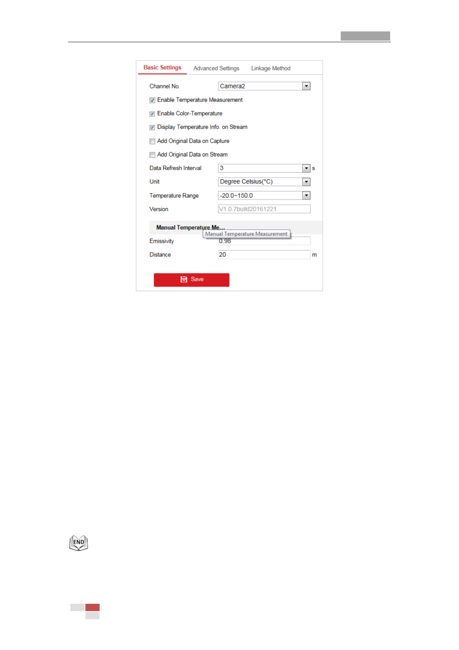
User Manual of Thermal Network Speed dome
© Hikvision
59
Figure 5-25 Dynamic Fire Source Detection
2. Check the checkboxes of the interface to set the temperature measurement
configurations.
Enabl
Enabl
Enabl
EnablEnable T
e T
e T
e Te Te
e
e
eemperat
mperat
mperat
mperatmperature M
ure M
ure M
ure Mure Measurement
easurement
easurement
easurementeasurement:
:
:
::
Check the checkbox to enable temperature
measurement function.
Enabl
Enabl
Enabl
EnablEnable
e
e
e e Col
Col
Col
ColColor
or
or
oror-T
-T
-T
-T-Temperature:
emperature:
emperature:
emperature:emperature:
Check the checkbox to display Temperature-Color
Ruler in live view.
Di
Di
Di
DiDispl
spl
spl
splsplay
ay
ay
ay ay T
T
T
TTemperat
emperat
emperat
emperatemperature
ure
ure
ure ure I
I
I
IInfo.
nfo.
nfo.
nfo.nfo.
on
on
on
on on S
S
S
SStream:
tream:
tream:
tream:tream:
Check the checkbox to display temperature
information in live view.
Ad
Ad
Ad
AdAdd Or
d Or
d Or
d Ord Ori
i
i
iigi
gi
gi
giginal
nal
nal
nalnal Data
Data
Data
Data Data on
on
on
on on Capture:
Capture:
Capture:
Capture:Capture: Check the checkbox to add original data on capture.
Ad
Ad
Ad
AdAdd Or
d Or
d Or
d Ord Ori
i
i
iigi
gi
gi
gigina
na
na
nanal
l
l
ll Data
Data
Data
Data Data on S
on S
on S
on Son Stream:
tream:
tream:
tream:tream: Check the checkbox to add original data on stream.
Data
Data
Data
DataData Refresh
Refresh
Refresh
Refresh Refresh Int
Int
Int
IntInter
er
er
ererval
val
val
valval:
:
:
:: Select the data refresh interval from 1s to 5s.
Uni
Uni
Uni
UniUnit:
t:
t:
t:t:
Display temperature with Degree Celsius (° C)/Degree Fahrenheit (° F)/Degree
Kelvin (K).
T
T
T
TTemperat
emperat
emperat
emperatemperature Range:
ure Range:
ure Range:
ure Range:ure Range: Set the temperature range.
Emiss
Emiss
Emiss
EmissEmissi
i
i
iivi
vi
vi
vivity
ty
ty
tyty:
:
:
::
Set the emissivity of your target. Note: The emissivity of each object is
different.
Di
Di
Di
DiDist
st
st
ststance
ance
ance
ance ance (m):
(m):
(m):
(m):(m):
The straight-line distance between the target and the device.
3. Clcik to save the settings .
Save
Save
Save
SaveSave

User Manual of Thermal Network Speed dome
© Hikvision
60
5.
5.
5.
5.5.4.
4.
4.
4.4.2
2
2
22 T
T
T
TTempera
empera
empera
emperaemperat
t
t
tture
ure
ure
ureure M
M
M
M Meas
eas
eas
easeasure
ure
ure
ureurement
ment
ment
mentment an
an
an
an and
d
d
d d A
A
A
AAl
l
l
llar
ar
ar
ararm
m
m
mm
Pu
Pu
Pu
PuPurpose
rpose
rpose
rposerpose:
:
:
::
This function is used for measuring the temperature of detected spot and the device
compares temperature of selected regions and alarms.
St
St
St
StSteps
eps
eps
epseps:
:
:
::
1. Enter Co
Co
Co
CoCon
n
n
nnfi
fi
fi
fifigu
gu
gu
gugurat
rat
rat
ratrati
i
i
iion
on
on
on on > T
> T
> T
> T> Tem
em
em
ememperat
perat
perat
peratperature M
ure M
ure M
ure Mure Measurement
easurement
easurement
easurementeasurement > A
> A
> A
> A > Adva
dva
dva
dvadvanced S
nced S
nced S
nced Snced Set
et
et
etetti
ti
ti
titin
n
n
nngs
gs
gs
gsgs.
2. Select the temperature measurement and alarm configuration as Norm
Norm
Norm
NormNormal
al
al
alal Exp
Exp
Exp
ExpExper
er
er
erert
t
t
tt or .
Normal
Normal
Normal
NormalNormal Mode
Mode
Mode
Mode Mode:
:
:
::
Figure 5-26 Temperature Measurement Configuration
Emiss
Emiss
Emiss
EmissEmissi
i
i
iivi
vi
vi
vivity
ty
ty
tyty:
:
:
::
Set the emissivity of your target. Note: The emissivity of each object
is different.
Di
Di
Di
DiDist
st
st
ststance
ance
ance
ance ance (m):
(m):
(m):
(m):(m):
The straight-line distance between the target and the device.
Pre
Pre
Pre
PrePre-
-
-
--Al
Al
Al
AlAla
a
a
aarm Threshol
rm Threshol
rm Threshol
rm Thresholrm Threshold
d
d
dd:
:
:
: : Set the pre-alarm temperature and the device sends
pre-alarm when its rule temperature exceeds pre-alarm temperature.
Al
Al
Al
AlAlarm
arm
arm
arm arm Thresh
Thresh
Thresh
ThreshThreshol
ol
ol
olold
d
d
dd:
:
:
: : Set the alarm temperature and the device sends alarm when
its rule temperature exceeds alarm temperature.

User Manual of Thermal Network Speed dome
© Hikvision
61
Exp
Exp
Exp
ExpExper
er
er
erert Mo
t Mo
t Mo
t Mot Mode:
de:
de:
de:de:
Figure 5-27 Temperature Measurement Configuration
1) Adjust the image to the scene for temperature measurement with the PTZ control
panel. Save current scene as certain preset.
You can set the preset in live view interface before and call the preset in the
temperature measurement and alarm interface.
You can set/ call/ clear the preset in temperature measurement interface.
2) Set the alarm rule: Select a temperature measurement rule from the rule list and
configure the parameters.
Name:
Name:
Name:
Name:Name:
You can customize the rule name.
T
T
T
TType:
ype:
ype:
ype:ype:
Poi
Poi
Poi
PoiPoint
nt
nt
ntnt Li
Li
Li
LiLine
ne
ne
nene Frame
Frame
Frame
FrameFrameSelect , , or as rule type.
Emiss
Emiss
Emiss
EmissEmissi
i
i
iiv
v
v
vvi
i
i
iity
ty
ty
tyty:
:
:
::
Set the emissivity of your target. The emissivity of each object is
different, you can refer to the Quick Start Guide Appendix for details.
Di
Di
Di
DiDist
st
st
ststance
ance
ance
ance ance (m):
(m):
(m):
(m):(m):
The straight-line distance between the target and the device.
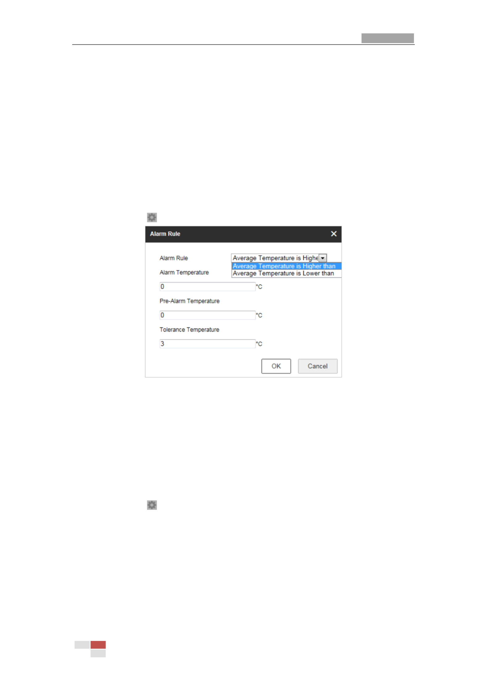
User Manual of Thermal Network Speed dome
© Hikvision
62
Refl
Refl
Refl
ReflReflecti
ecti
ecti
ectiective
ve
ve
ve ve T
T
T
TTem
em
em
ememper
per
per
perperature:
ature:
ature:
ature:ature:
If there is any target with high emissivity in the scene,
check the checkbox and set the reflective temperature to correct the
temperature. If no such target exists, uncheck the checkbox.
T
T
T
TTol
ol
ol
ololerance
erance
erance
eranceerance
T
T
T
TTem
em
em
ememper
per
per
perperature:
ature:
ature:
ature:ature:
The device judges whether the triggered alarm stops
until the device temperature/temperature difference is lower than rule
temperature by tolerance temperature. E.g., set tolerance temperature as 3° C,
set alarm temperature as 55° C, and set pre-alarm temperature as 50°C. The
device sends pre-alarm when its temperature reaches 50° C and it alarms when
its temperature reaches 55° C and only when the device temperature is lower
than 52° C will the alarm be cancelled.
3) Set the alarm rules.
For Po
For Po
For Po
For PoFor Poin
in
in
inint Rule
t Rule
t Rule
t Rulet Rule:
:
:
::
a) Click to show the Alarm Rule setting interface.
Figure 5-28 Alarm Rule Settings (Point)
b) Set the alarm rule.
c) Set the Alarm Temperature, Pre-Alarm Temperature, and Tolerance
Temperature.
E.g., select Alarm Rule as Aver
Aver
Aver
AverAverage
age
age
age age T
T
T
TTemperatu
emperatu
emperatu
emperatuemperature
re
re
re re i
i
i
iis
s
s
s s Hi
Hi
Hi
HiHigher
gher
gher
gher gher than
than
than
thanthan, and set the
Alarm Temperature to 50 ° C, and the device alarms when its average
temperature is higher than 50 °C.
For Li
For Li
For Li
For LiFor Line Rul
ne Rul
ne Rul
ne Rulne Rule:
e:
e:
e:e:
a) Click to show the Alarm Rule setting interface.

User Manual of Thermal Network Speed dome
© Hikvision
63
Figure 5-29 Alarm Rule Settings (Line)
b) Set the alarm rule.
c) Set the Alarm Temperature, Pre-Alarm Temperature, and Tolerance
Temperature.
E.g., select Alarm Rule as Min
Min
Min
MinMin.
.
.
..
T
T
T
TTemperat
emperat
emperat
emperatemperature
ure
ure
ure ure i
i
i
iis
s
s
s s Lo
Lo
Lo
LoLow
w
w
wwer
er
er
erer
t
t
t
tthan
han
han
hanhan, and set the Alarm
Temperature to 40 ° C, and the device alarms when the minimum temperature is
lower than 40 ° C.
For Frame R
For Frame R
For Frame R
For Frame RFor Frame Rul
ul
ul
ulule:
e:
e:
e:e:
T
T
T
TTas
as
as
asask
k
k
kk 1.
1.
1.
1. 1.
a) Click to show the Alarm Rule setting interface.
Figure 5-30 Alarm Rule Settings (Frame)
b) Set the alarm rule.
c) Set the Alarm Temperature, Pre-Alarm Temperature, and Tolerance
Temperature.
E.g., select Alarm Rule as T
T
T
TTemperatu
emperatu
emperatu
emperatuemperature
re
re
re re Di
Di
Di
DiDiffe
ffe
ffe
ffefference
rence
rence
rence rence i
i
i
iis
s
s
s s Hi
Hi
Hi
HiHigher
gher
gher
ghergher
than
than
than
thanthan, and set the
Alarm Temperature to 10 ° C, and the device alarms when the difference
between the minimum temperature and the maximum temperature of the
region is higher than 10 °C.

User Manual of Thermal Network Speed dome
© Hikvision
64
T
T
T
TTask
ask
ask
askask 2.
2.
2.
2. 2.
For two alarm rules of frame, you can set the alarm for region temperature
difference.
a) Set the frame alarm rules.
b) Click to show the region temperature
difference alarm interface.
Figure 5-31 Region Temperature Difference Alarm
c) Select two rules to compare the saved regions.
d) Set the alarm rules and the temperature.
E.g., select Alarm Rule as T
T
T
TTe
e
e
eemperatu
mperatu
mperatu
mperatumperature
re
re
re re Di
Di
Di
DiDif
f
f
ffference
ference
ference
ference ference i
i
i
iis
s
s
ss
Hi
Hi
Hi
HiHighe
ghe
ghe
ghegher
r
r
r r t
t
t
tthan
han
han
hanhan, and enter
10 °C, the device alarms when the difference between the minimum
temperature and the maximum temperature of the region is higher than 10 °C.
Temperature Difference Alarm only applies to the targets set by frame.
3. Set Alarm Linkage: Click Alarm Linkage to enter the alarm linkage interface and set the
linkage methods. Refer to Step 3 in Section 5.2.1 Configuring Motion Detection. In the
field of , you can check the checkbox to enable the alarm output (The
Othe
Othe
Othe
OtheOther
r
r
r r Li
Li
Li
LiLink
nk
nk
nknkag
ag
ag
agage
e
e
ee
alarm output number varies depending on device ability).
4. Click to save the settings.
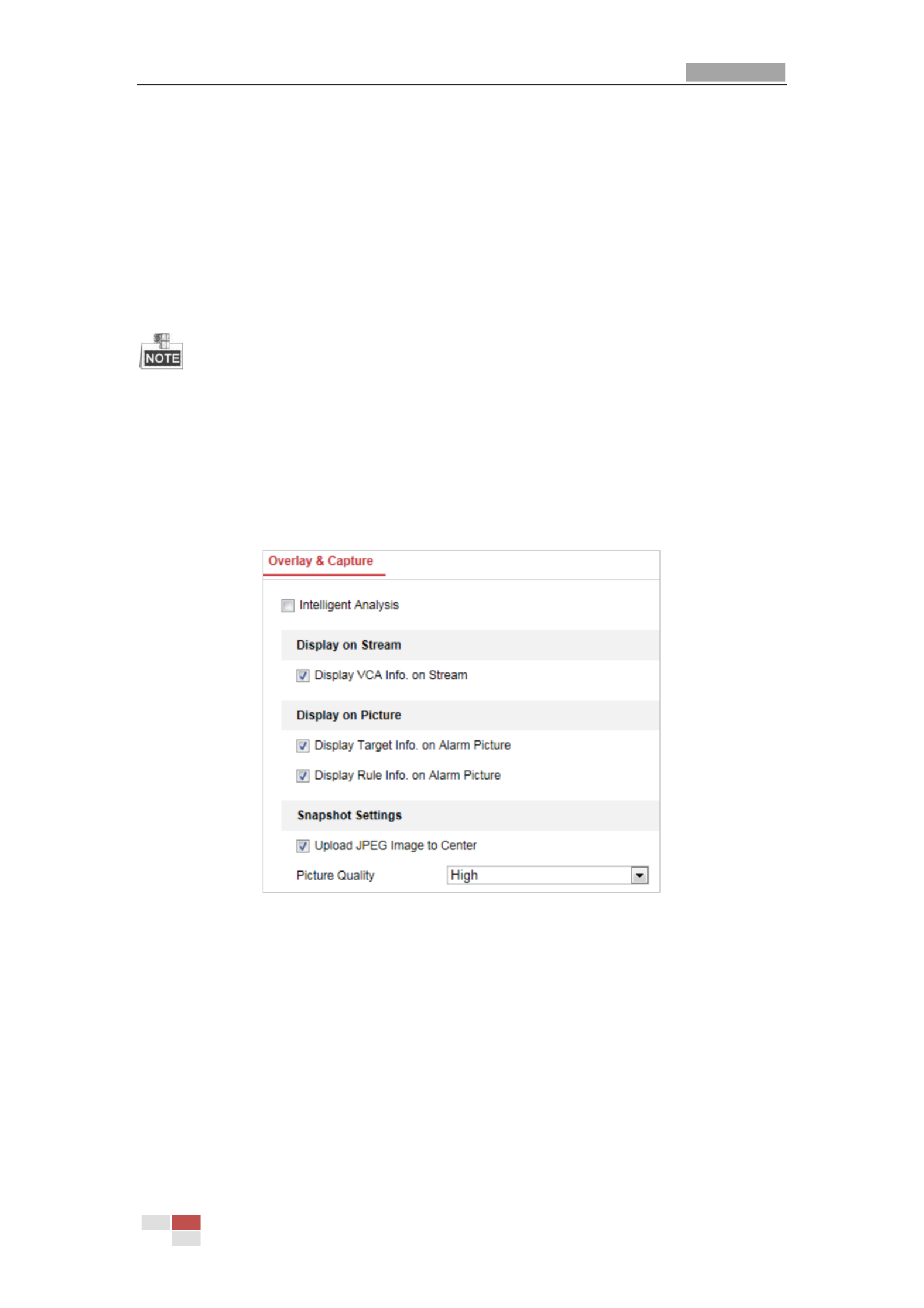
User Manual of Thermal Network Speed dome
© Hikvision
65
Chap
Chap
Chap
ChapChapt
t
t
tter
er
er
erer 6
6
6
6 6
V
V
V
VVC
C
C
CCA
A
A
AA Con
Con
Con
Con Conf
f
f
ffi
i
i
iig
g
g
ggur
ur
ur
ururat
at
at
atati
i
i
iion
on
on
onon
Be
Be
Be
BeBefore you s
fore you s
fore you s
fore you sfore you star
tar
tar
tartart:
t:
t:
t:t:
Go to Confi
Confi
Confi
ConfiConfigura
gura
gura
guraguratio
tio
tio
tiotion
n
n
n n >
>
>
> > Syst
Syst
Syst
SystSystem
em
em
em em >
>
>
> > Mai
Mai
Mai
MaiMaint
nt
nt
ntntenance
enance
enance
enance enance >
>
>
> > VCA
VCA
VCA
VCAVCA
Resource
Resource
Resource
Resource Resource T
T
T
TType
ype
ype
ypeype and select the VCA
Resource as T
T
T
TTem
em
em
ememp
p
p
pperatu
eratu
eratu
eratuerature Measurement
re Measurement
re Measurement
re Measurementre Measurement + Behavi
+ Behavi
+ Behavi
+ Behavi + Behavior Anal
or Anal
or Anal
or Analor Analys
ys
ys
ysysis
is
is
isis.
Pu
Pu
Pu
PuPurpose:
rpose:
rpose:
rpose:rpose:
You can do intelligent analysis, such as behavior analysis, with the speed dome. Multiple
rules can be configured for different requirements.
The VCA (Video Content Analysis) function only supported by the thermal channel.
6.
6.
6.
6.6.1
1
1
11 Conf
Conf
Conf
ConfConfi
i
i
iig
g
g
gguri
uri
uri
uriuring
ng
ng
ngng V
V
V
V VC
C
C
CCA
A
A
AA I
I
I
I Info
nfo
nfo
nfonformati
rmati
rmati
rmatirmation
on
on
onon
St
St
St
StSteps:
eps:
eps:
eps:eps:
1. Enter the VCA Information Configuration interface:
Conf
Conf
Conf
ConfConfigura
igura
igura
iguraigurati
ti
ti
tition > VCA
on > VCA
on > VCA
on > VCA on > VCA C
C
C
CCo
o
o
oonfi
nfi
nfi
nfinfigurat
gurat
gurat
guratguration
ion
ion
ionion > VCA In
> VCA In
> VCA In
> VCA In > VCA Info.
fo.
fo.
fo.fo.
Figure 6-1 VCA Information
2. Check the checkbox to enable the Intelligent Analysis. And you can view the current
version for the behavior analysis.
3. Set the display information:
If you select to display the target info and rule info on the alarm picture are
supported; you can enable the functions by ticking the corresponding checkbox on
your demand.
And if you tick the checkbox of display target info and rule on stream, the
information will be added to the video stream, and the overlay will be displayed if
you get live view or play back by the VS Player.
4. Set the Snapshot:

User Manual of Thermal Network Speed dome
© Hikvision
66
You can configure the function which is used for
No
No
No
NoNoti
ti
ti
titify
fy
fy
fyfy
Su
Su
Su
SuSurv
rv
rv
rvrvei
ei
ei
eieil
l
l
lll
l
l
llanc
anc
anc
ancance
e
e
e e Cent
Cent
Cent
CentCenter
er
er
er er
uploading the picture to the surveillance center when and VCA alarm occurs.
You can also set the quality and resolution of the picture separately.
5. Click to save the settings.
6.
6.
6.
6.6.2
2
2
22 A
A
A
AAd
d
d
ddva
va
va
vavan
n
n
nnce
ce
ce
ceced Con
d Con
d Con
d Cond Conf
f
f
ffi
i
i
iig
g
g
ggur
ur
ur
urura
a
a
aat
t
t
tti
i
i
iion
on
on
onon
All the parameters for both behavior analysis and face capture are collected in the
advanced configuration page. You can configure these parameters for different VCA types
on your demand.
St
St
St
StSteps
eps
eps
epseps:
:
:
::
1. Enter the Advanced Configuration interface:
Conf
Conf
Conf
ConfConfi
i
i
iigurat
gurat
gurat
guratgurati
i
i
iion > V
on > V
on > V
on > Von > VCA > A
CA > A
CA > A
CA > ACA > Adva
dva
dva
dvadvanced Con
nced Con
nced Con
nced Connced Confi
fi
fi
fifig
g
g
ggurat
urat
urat
uraturati
i
i
iion
on
on
onon
Figure 6-2 Advanced Configuration
2. Adjust the Detection Parameters.
Dete
Dete
Dete
DeteDetecti
cti
cti
ctiction S
on S
on S
on Son Sensi
ensi
ensi
ensiensiti
ti
ti
titiv
v
v
vvi
i
i
iit
t
t
tty
y
y
yy:
:
:
:: Range [0-4], the higher the sensitivity is, the easier the target will
be detected.
Ba
Ba
Ba
BaBackg
ckg
ckg
ckgckground
round
round
round round Upd
Upd
Upd
UpdUpdat
at
at
atate
e
e
e e R
R
R
RRat
at
at
atate:
e:
e:
e:e:
Range [0-4], if a detected target remains in the monitoring
scene for a certain time, the system will count the target as the background
automatically. The greater the value is, the faster the target will be counted as the
background.
Mi
Mi
Mi
MiMini
ni
ni
ninimum
mum
mum
mum mum T
T
T
TTarg
arg
arg
argarget
et
et
et et Si
Si
Si
SiSize:
ze:
ze:
ze:ze:
Range [0-4], The system will filter out the object smaller than
the minimum target size.
Product specificaties
| Merk: | Hikvision |
| Categorie: | Bewakingscamera |
| Model: | DS-2TD4136T-9 |
| Kleur van het product: | Black, White |
| Gewicht: | 8000 g |
| Hoogte: | 198.6 mm |
| Soort: | IP-beveiligingscamera |
| Internationale veiligheidscode (IP): | IP66 |
| Bluetooth: | Nee |
| Maximale capaciteit van de geheugenkaart: | 64 GB |
| Ondersteund audioformaat: | PCM |
| Stemcodecs: | G.711a, G.711u, G.722.1, G.726, MP2L2 |
| Vormfactor: | Dome |
| Automatisch scherpstellen: | Ja |
| Ondersteuning voor plaatsing: | Buiten |
| Connectiviteitstechnologie: | Bedraad |
| Ethernet LAN: | Ja |
| Montagewijze: | Plafond/muur |
| Maximum resolutie: | - Pixels |
| Totaal aantal megapixels: | - MP |
| Videocompressieformaten: | H.264, M-JPEG, MPEG4 |
| Diameter: | 266.6 mm |
| Type stroombron: | AC |
| Minimale belichting: | 0.0002 Lux |
| Aantal cameras: | 1 |
| Geïntegreerde geheugenkaartlezer: | Ja |
| Compatibele geheugenkaarten: | MicroSD (TransFlash), MicroSDHC, MicroSDXC |
| Ingebouwde HDD: | Nee |
| Nachtvisie: | Ja |
| LED-type: | IR |
| Vaste focale lengte: | 9 mm |
| Zoomcapaciteit: | Ja |
| Microfoon, line-in ingang: | Ja |
| Aantal Ethernet LAN (RJ-45)-poorten: | 1 |
| Brandpuntbereik: | 5.7 - 205.2 mm |
| Vermogensverbruik (max): | 60 W |
| Hoofdtelefoonuitgangen: | 1 |
| Formaat analoog signaal: | NTSC, PAL |
| Omvang optische sensor: | 1/1.9 " |
| Type beeldsensor: | CMOS |
| Digitale zoom: | 16 x |
| Camera sluitertijd: | 1/1-1/30000 s |
| Interface: | RJ-45 |
| Witbalans: | Auto, Daylight, Indoor, Manual, Outdoor, Sodium lamp |
| Ondersteunde grafische resoluties: | 176 x 120,176 x 144,352 x 240,352 x 288,384 x 288,704 x 480,704 x 576,1280 x 720 (HD 720),1280 x 960,1920 x 1080 (HD 1080) |
| Webbrowser: | Ja |
| Ruisonderdrukking: | Ja |
| Bekabelingstechnologie: | 10/100Base-T(X) |
| Netwerkstandaard: | IEEE 802.1x |
| Ondersteunde beveiligingsalgoritmen: | HTTPS |
| Aantal gebruikers: | 32 gebruiker(s) |
| Maximaal 30 frames per seconde: | 50 fps |
| Ondersteunde netwerkprotocollen: | IPv4/IPv6, HTTP, HTTPS, 802.1x, Qos, FTP, SMTP, UPnP, SNMP, DNS, DDNS, NTP, RTSP, RTCP, RTP, TCP, UDP, IG MP, ICMP, DHCP, PPPoE, Bonjourl |
| Web-gebaseerd management: | Ja |
| IP-adresfilter: | Ja |
| Progressive scan: | Ja |
| Ethernet interface type: | Fast Ethernet |
| Ondersteunde talen: | Engels |
| Quality of Service (QoS): | Ja |
| Dichtstbijzijnde focus afstand: | 1.5 m |
| Type sterkteregeling: | Auto |
| PTZ control: | Ja |
| Pan bereik: | 0 - 360 ° |
| Dag/nacht modus: | Ja |
| Aantal lenzen: | 1 |
| Maximum aperture number: | 4.5 |
| Minimum aperture number: | 1.5 |
| Controle camerapanning: | Ja |
| Kantelfunctie camera: | Ja |
| Draai-snelheid: | 120 °/sec |
| Pan snelheid: | 160 °/sec |
| Vooringestelde snelheid pan: | 240 °/sec |
| Aantal sensoren: | 1 |
| Videostreaming: | Ja |
| Nachtkijker afstand: | 200 m |
| Infrarood (IR)-afsluitingsfilter: | Ja |
| Alarm ingang/uitgang: | Ja |
| Wide Dynamic Range (WDR): | Ja |
| Wifi: | Nee |
| AC-ingangsspanning: | 24 V |
| Bedrijfstemperatuur (T-T): | -40 - 60 °C |
| Relatieve vochtigheid in bedrijf (V-V): | 0 - 90 procent |
| Bereik kantelhoek: | -15 - 90 ° |
| Privézone maskeren: | Ja |
| RS-485 ports: | 1 |
| Ruisonderdrukkingstechnologie: | 3D-ruisonderdrukking |
| Temperatuursensor: | Ja |
| 3D-geluidsreductie: | Ja |
| Thermische module: | Ja |
| Vooringestelde snelheid tilt: | 200 °/sec |
Heb je hulp nodig?
Als je hulp nodig hebt met Hikvision DS-2TD4136T-9 stel dan hieronder een vraag en andere gebruikers zullen je antwoorden
Handleiding Bewakingscamera Hikvision

7 Februari 2025
7 Februari 2025
7 Februari 2025
7 Februari 2025
7 Februari 2025
7 Februari 2025
5 Februari 2025
5 Februari 2025
6 Januari 2025
18 December 2024
Handleiding Bewakingscamera
- Bewakingscamera Braun
- Bewakingscamera Bosch
- Bewakingscamera Philips
- Bewakingscamera Sony
- Bewakingscamera Samsung
- Bewakingscamera Xiaomi
- Bewakingscamera Panasonic
- Bewakingscamera Asus
- Bewakingscamera Canon
- Bewakingscamera Garmin
- Bewakingscamera Grundig
- Bewakingscamera Gigaset
- Bewakingscamera Honeywell
- Bewakingscamera JVC
- Bewakingscamera Motorola
- Bewakingscamera Pioneer
- Bewakingscamera Toshiba
- Bewakingscamera VTech
- Bewakingscamera Abus
- Bewakingscamera ACME
- Bewakingscamera Acti
- Bewakingscamera Ag Neovo
- Bewakingscamera Airlive
- Bewakingscamera Aldi
- Bewakingscamera Alecto
- Bewakingscamera Allnet
- Bewakingscamera Aluratek
- Bewakingscamera Anker
- Bewakingscamera Apc
- Bewakingscamera Aqara
- Bewakingscamera Aritech
- Bewakingscamera Avanti
- Bewakingscamera AVTech
- Bewakingscamera Axis
- Bewakingscamera Beafon
- Bewakingscamera Belkin
- Bewakingscamera Blaupunkt
- Bewakingscamera Boss
- Bewakingscamera Brinno
- Bewakingscamera BRK
- Bewakingscamera Buffalo
- Bewakingscamera Burg-Wachter
- Bewakingscamera D-Link
- Bewakingscamera Dedicated Micros
- Bewakingscamera Denver
- Bewakingscamera Digitus
- Bewakingscamera DIO
- Bewakingscamera Dorr
- Bewakingscamera E-bench
- Bewakingscamera Ebode
- Bewakingscamera Edimax
- Bewakingscamera Ednet
- Bewakingscamera Elmo
- Bewakingscamera Elro
- Bewakingscamera Eminent
- Bewakingscamera Engenius
- Bewakingscamera Eufy
- Bewakingscamera EverFocus
- Bewakingscamera Extech
- Bewakingscamera Ezviz
- Bewakingscamera Ferguson
- Bewakingscamera First Alert
- Bewakingscamera Flamingo
- Bewakingscamera Flir
- Bewakingscamera Foscam
- Bewakingscamera Friedland
- Bewakingscamera Ganz
- Bewakingscamera Gembird
- Bewakingscamera Genius
- Bewakingscamera GeoVision
- Bewakingscamera Gira
- Bewakingscamera Google
- Bewakingscamera Grandstream
- Bewakingscamera Hama
- Bewakingscamera Iget
- Bewakingscamera Iiquu
- Bewakingscamera Iluv
- Bewakingscamera Indexa
- Bewakingscamera InFocus
- Bewakingscamera Interlogix
- Bewakingscamera Ion
- Bewakingscamera Kerbl
- Bewakingscamera KlikaanKlikuit
- Bewakingscamera Kodak
- Bewakingscamera Kogan
- Bewakingscamera Konig
- Bewakingscamera Laserliner
- Bewakingscamera LevelOne
- Bewakingscamera Linksys
- Bewakingscamera Logilink
- Bewakingscamera Logitech
- Bewakingscamera Lorex
- Bewakingscamera Maginon
- Bewakingscamera Manhattan
- Bewakingscamera Marmitek
- Bewakingscamera Marquant
- Bewakingscamera Marshall
- Bewakingscamera Megasat
- Bewakingscamera Minox
- Bewakingscamera Mitsubishi
- Bewakingscamera Monacor
- Bewakingscamera Nedis
- Bewakingscamera Nest
- Bewakingscamera Netatmo
- Bewakingscamera Netgear
- Bewakingscamera Netis
- Bewakingscamera Notifier
- Bewakingscamera Perel
- Bewakingscamera Powerfix
- Bewakingscamera Profile
- Bewakingscamera Provision ISR
- Bewakingscamera Pyle
- Bewakingscamera Quantum
- Bewakingscamera Raymarine
- Bewakingscamera Renkforce
- Bewakingscamera Revo
- Bewakingscamera Ricoh
- Bewakingscamera Ring
- Bewakingscamera Rollei
- Bewakingscamera Sanyo
- Bewakingscamera Satel
- Bewakingscamera Schneider
- Bewakingscamera SecurityMan
- Bewakingscamera Siedle
- Bewakingscamera Sitecom
- Bewakingscamera Smartwares
- Bewakingscamera SMC
- Bewakingscamera Somfy
- Bewakingscamera Sonic Alert
- Bewakingscamera Stabo
- Bewakingscamera Strong
- Bewakingscamera Switel
- Bewakingscamera Synology
- Bewakingscamera Technaxx
- Bewakingscamera Tenda
- Bewakingscamera Thomson
- Bewakingscamera TP Link
- Bewakingscamera Trebs
- Bewakingscamera Trendnet
- Bewakingscamera Trust
- Bewakingscamera Uniden
- Bewakingscamera V-Tac
- Bewakingscamera Velleman
- Bewakingscamera Vitek
- Bewakingscamera Vivotek
- Bewakingscamera Waeco
- Bewakingscamera Western Digital
- Bewakingscamera Withings
- Bewakingscamera Woonveilig
- Bewakingscamera Xavax
- Bewakingscamera Y-cam
- Bewakingscamera Yale
- Bewakingscamera Zebra
- Bewakingscamera ZTE
- Bewakingscamera ZyXEL
- Bewakingscamera Jung
- Bewakingscamera Olympia
- Bewakingscamera Oplink
- Bewakingscamera Orion
- Bewakingscamera Overmax
- Bewakingscamera Clas Ohlson
- Bewakingscamera Caliber
- Bewakingscamera Exibel
- Bewakingscamera Monoprice
- Bewakingscamera Naxa
- Bewakingscamera Niceboy
- Bewakingscamera Schwaiger
- Bewakingscamera Steren
- Bewakingscamera Ubiquiti Networks
- Bewakingscamera EMOS
- Bewakingscamera Conceptronic
- Bewakingscamera Miniland
- Bewakingscamera Arlo
- Bewakingscamera Atlona
- Bewakingscamera Avidsen
- Bewakingscamera Hamlet
- Bewakingscamera Hive
- Bewakingscamera Imou
- Bewakingscamera INSTAR
- Bewakingscamera SereneLife
- Bewakingscamera Defender
- Bewakingscamera Trevi
- Bewakingscamera Adesso
- Bewakingscamera Broan
- Bewakingscamera DSC
- Bewakingscamera M-e
- Bewakingscamera Blow
- Bewakingscamera Genie
- Bewakingscamera ClearOne
- Bewakingscamera Chacon
- Bewakingscamera Swann
- Bewakingscamera Approx
- Bewakingscamera SPC
- Bewakingscamera Canyon
- Bewakingscamera Cisco
- Bewakingscamera EVOLVEO
- Bewakingscamera Whistler
- Bewakingscamera Delta Dore
- Bewakingscamera Furrion
- Bewakingscamera Comtrend
- Bewakingscamera Planet
- Bewakingscamera Blink
- Bewakingscamera Intellinet
- Bewakingscamera Aida
- Bewakingscamera Lindy
- Bewakingscamera AVerMedia
- Bewakingscamera Lumens
- Bewakingscamera Mobi
- Bewakingscamera Fortinet
- Bewakingscamera DataVideo
- Bewakingscamera Hombli
- Bewakingscamera Vaddio
- Bewakingscamera Adj
- Bewakingscamera Ikan
- Bewakingscamera Dahua Technology
- Bewakingscamera UniView
- Bewakingscamera Reolink
- Bewakingscamera Valueline
- Bewakingscamera EVE
- Bewakingscamera QSC
- Bewakingscamera Marshall Electronics
- Bewakingscamera Boyo
- Bewakingscamera IC Intracom
- Bewakingscamera CRUX
- Bewakingscamera POSline
- Bewakingscamera August
- Bewakingscamera Hawking Technologies
- Bewakingscamera Lanberg
- Bewakingscamera Nexxt
- Bewakingscamera Watec
- Bewakingscamera Equip
- Bewakingscamera Crestron
- Bewakingscamera Chuango
- Bewakingscamera ORNO
- Bewakingscamera ETiger
- Bewakingscamera Videcon
- Bewakingscamera Advantech
- Bewakingscamera Moxa
- Bewakingscamera Digital Watchdog
- Bewakingscamera Brilliant
- Bewakingscamera Moen
- Bewakingscamera Kramer
- Bewakingscamera MEE Audio
- Bewakingscamera Brickcom
- Bewakingscamera Kwikset
- Bewakingscamera Linear PRO Access
- Bewakingscamera BirdDog
- Bewakingscamera AVer
- Bewakingscamera Summer Infant
- Bewakingscamera Topica
- Bewakingscamera Vimar
- Bewakingscamera Speco Technologies
- Bewakingscamera Verint
- Bewakingscamera ZKTeco
- Bewakingscamera Rostra
- Bewakingscamera Kguard
- Bewakingscamera Caddx
- Bewakingscamera Spyclops
- Bewakingscamera EKO
- Bewakingscamera Inovonics
- Bewakingscamera Surveon
- Bewakingscamera Hollyland
- Bewakingscamera Epcom
- Bewakingscamera AViPAS
- Bewakingscamera Lutec
- Bewakingscamera Hanwha
- Bewakingscamera ClearView
- Bewakingscamera VideoComm
- Bewakingscamera IMILAB
- Bewakingscamera InfiRay
- Bewakingscamera 3xLOGIC
- Bewakingscamera Pelco
- Bewakingscamera Leviton
- Bewakingscamera EtiamPro
- Bewakingscamera Inkovideo
- Bewakingscamera Pentatech
- Bewakingscamera Weldex
- Bewakingscamera CNB Technology
- Bewakingscamera Tapo
- Bewakingscamera Aigis
- Bewakingscamera Exacq
- Bewakingscamera Laxihub
- Bewakingscamera Securetech
- Bewakingscamera EFB Elektronik
- Bewakingscamera Ernitec
- Bewakingscamera NetMedia
- Bewakingscamera Videotec
- Bewakingscamera Illustra
- Bewakingscamera AVMATRIX
- Bewakingscamera Nivian
- Bewakingscamera Arenti
- Bewakingscamera Syscom
- Bewakingscamera Tecno
- Bewakingscamera Night Owl
- Bewakingscamera Guardzilla
- Bewakingscamera Astak
- Bewakingscamera Milestone Systems
- Bewakingscamera Zavio
- Bewakingscamera Campark
- Bewakingscamera IPX
- Bewakingscamera Promise Technology
- Bewakingscamera Annke
- Bewakingscamera Qoltec
- Bewakingscamera Digimerge
- Bewakingscamera Alfatron
- Bewakingscamera Feelworld
- Bewakingscamera KJB Security Products
- Bewakingscamera British Telecom
- Bewakingscamera Wisenet
- Bewakingscamera Ecobee
- Bewakingscamera BZBGear
- Bewakingscamera WyreStorm
- Bewakingscamera Infortrend
- Bewakingscamera Epiphan
- Bewakingscamera HiLook
- Bewakingscamera Mach Power
- Bewakingscamera Compro
- Bewakingscamera Ikegami
- Bewakingscamera Accsoon
- Bewakingscamera Vimtag
- Bewakingscamera Sonoff
- Bewakingscamera Gewiss
- Bewakingscamera Alula
- Bewakingscamera Insteon
- Bewakingscamera Costar
- Bewakingscamera ALC
- Bewakingscamera Security Labs
- Bewakingscamera American Dynamics
- Bewakingscamera Seneca
- Bewakingscamera Avigilon
- Bewakingscamera Vosker
- Bewakingscamera Sentry360
- Bewakingscamera Bea-fon
- Bewakingscamera Owltron
- Bewakingscamera Petcube
- Bewakingscamera Enabot
- Bewakingscamera Luis Energy
- Bewakingscamera Sir Gawain
- Bewakingscamera VisorTech
- Bewakingscamera Atlantis Land
- Bewakingscamera B & S Technology
- Bewakingscamera I3International
- Bewakingscamera IDIS
- Bewakingscamera Turing
- Bewakingscamera Qian
- Bewakingscamera Wasserstein
- Bewakingscamera Qolsys
- Bewakingscamera Control4
- Bewakingscamera Milesight
- Bewakingscamera GVI Security
- Bewakingscamera Conbrov
- Bewakingscamera HuddleCamHD
- Bewakingscamera Setti+
- Bewakingscamera Mobotix
- Bewakingscamera IOIO
- Bewakingscamera BIRDFY
- Bewakingscamera I-PRO
- Bewakingscamera DVDO
- Bewakingscamera TCP
- Bewakingscamera Bolin Technology
- Bewakingscamera Konyks
- Bewakingscamera Nextech
- Bewakingscamera Arecont Vision
- Bewakingscamera YoloLiv
Nieuwste handleidingen voor Bewakingscamera

30 Maart 2025
29 Maart 2025
29 Maart 2025
29 Maart 2025
29 Maart 2025
29 Maart 2025
27 Maart 2025
27 Maart 2025
27 Maart 2025
26 Maart 2025