Hikvision DS-2CD6944G0-IHS(/NFC) Handleiding
Hikvision
Bewakingscamera
DS-2CD6944G0-IHS(/NFC)
Lees hieronder de 📖 handleiding in het Nederlandse voor Hikvision DS-2CD6944G0-IHS(/NFC) (132 pagina's) in de categorie Bewakingscamera. Deze handleiding was nuttig voor 34 personen en werd door 2 gebruikers gemiddeld met 4.5 sterren beoordeeld
Pagina 1/132

Network Camera User Manual
0
User Manual
UD15753B
Network Camera

Network Camera User Manual
1
User Manual
© 2019 Hangzhou Hikvision Digital Technology Co., Ltd. All rights reserved.
This Manual is the property of Hangzhou Hikvision Digital Technology Co., Ltd. or its
aliates (hereinaer referred to as "Hikvision"), and it cannot be reproduced,
changed, translated, or distributed, parally or wholly, by any means, without the
prior wrien permission of Hikvision. Unless otherwise expressly stated herein,
Hikvision does not make any warranes, guarantees or representaons, express or
implied, regarding to the Manual, any informaon contained herein.
About this Manual
The Manual includes instrucons for using and managing the Product. Pictures,
charts, images and all other informaon hereinaer are for descripon and
explanaon only. The informaon contained in the Manual is subject to change,
without noce, due to rmware updates or other reasons. Please nd the latest
version of this Manual at the Hikvision website (hp://www.hikvision.com).
Please use this Manual with the guidance and assistance of professionals trained in
supporng the Product.
Trademarks Acknowledgement
and other Hikvision’s trademarks and logos are the properes of
Hikvision in various jurisdicons.
Other trademarks and logos menoned are the properes of their respecve
owners.
The terms HDMI and HDMI High Denion Mulmedia Interface, and -
the HDMI Logo are trademarks or registered trademarks of HDMI Licensing
Administrator, Inc. in the United States and other countries.
LEGAL DISCLAIMER
TO THE MAXIMUM EXTENT PERMITTED BY APPLICABLE LAW, THIS MANUAL AND
THE PRODUCT DESCRIBED, WITH ITS HARDWARE, SOFTWARE AND FIRMWARE, ARE
PROVIDED "AS IS" AND "WITH ALL FAULTS AND ERRORS". HIKVISION MAKES NO
WARRANTIES, EXPRESS OR IMPLIED, INCLUDING WITHOUT LIMITATION,
MERCHANTABILITY, SATISFACTORY QUALITY, OR FITNESS FOR A PARTICULAR

Network Camera User Manual
2
PURPOSE. THE USE OF THE PRODUCT BY YOU IS AT YOUR OWN RISK. IN NO EVENT
WILL HIKVISION BE LIABLE TO YOU FOR ANY SPECIAL, CONSEQUENTIAL, INCIDENTAL,
OR INDIRECT DAMAGES, INCLUDING, AMONG OTHERS, DAMAGES FOR LOSS OF
BUSINESS PROFITS, BUSINESS INTERRUPTION, OR LOSS OF DATA, CORRUPTION OF
SYSTEMS, OR LOSS OF DOCUMENTATION, WHETHER BASED ON BREACH OF
CONTRACT, TORT (INCLUDING NEGLIGENCE), PRODUCT LIABILITY, OR OTHERWISE,
IN CONNECTION WITH THE USE OF THE PRODUCT, EVEN IF HIKVISION HAS BEEN
ADVISED OF THE POSSIBILITY OF SUCH DAMAGES OR LOSS.
YOU ACKNOWLEDGE THAT THE NATURE OF INTERNET PROVIDES FOR INHERENT
SECURITY RISKS, AND HIKVISION SHALL NOT TAKE ANY RESPONSIBILITIES FOR
ABNORMAL OPERATION, PRIVACY LEAKAGE OR OTHER DAMAGES RESULTING FROM
CYBER-ATTACK, HACKER ATTACK, VIRUS INSPECTION, OR OTHER INTERNET SECURITY
RISKS; HOWEVER, HIKVISION WILL PROVIDE TIMELY TECHNICAL SUPPORT IF
REQUIRED.
YOU AGREE TO USE THIS PRODUCT IN COMPLIANCE WITH ALL APPLICABLE LAWS,
AND YOU ARE SOLELY RESPONSIBLE FOR ENSURING THAT YOUR USE CONFORMS TO
THE APPLICABLE LAW. ESPECIALLY, YOU ARE RESPONSIBLE, FOR USING THIS
PRODUCT IN A MANNER THAT DOES NOT INFRINGE ON THE RIGHTS OF THIRD
PARTIES, INCLUDING WITHOUT LIMITATION, RIGHTS OF PUBLICITY, INTELLECTUAL
PROPERTY RIGHTS, OR DATA PROTECTION AND OTHER PRIVACY RIGHTS. YOU SHALL
NOT USE THIS PRODUCT FOR ANY PROHIBITED END-USES, INCLUDING THE
DEVELOPMENT OR PRODUCTION OF WEAPONS OF MASS DESTRUCTION, THE
DEVELOPMENT OR PRODUCTION OF CHEMICAL OR BIOLOGICAL WEAPONS, ANY
ACTIVITIES IN THE CONTEXT RELATED TO ANY NUCLEAR EXPLOSIVE OR UNSAFE
NUCLEAR FUEL-CYCLE, OR IN SUPPORT OF HUMAN RIGHTS ABUSES.

Network Camera User Manual
3
IN THE EVENT OF ANY CONFLICTS BETWEEN THIS MANUAL AND THE APPLICABLE
LAW, THE LATER PREVAILS. Safety Instrucon
These instrucons are intended to ensure that the user can use the product correctly
to avoid danger or property loss.
The precauon measure is divided into ‘Warnings’ and ‘Cauons’:
Warnings: Serious injury or death may be caused if any of these warnings are
neglected.
Cauons: Injury or equipment damage may be caused if any of these cauons are
neglected.
Warnings Follow these safeguards to
prevent serious injury or death.
Cauons Follow these precauons to
prevent potenal injury or material
damage.
Warnings:
Please adopt the power adapter which can meet the safety extra low voltage
(SELV) standard. And source with 12 V or 24 VDC AC (depending on models)
according to the IEC60950 1 and Limited Power Source standard.-
To reduce the risk of re or electrical shock, do not expose this product to rain or
moisture.
This installaon should be made by a qualied service person and should
conform to all the local codes.
Please install blackouts equipment into the power supply circuit for convenient
Notice:
If camera fails to synchronize local time with that of the network, you need to set
up camera time manually. Visit the camera and enter system setting interface for
time setting.

Network Camera User Manual
4
supply interrupon.
Please make sure that the ceiling can support more than 50(N) Newton gravies
if the camera is xed to the ceiling.
If the product does not work properly, please contact your dealer or the nearest
service center. Never aempt to disassemble the camera yourself. (We shall not
assume any responsibility for problems caused by unauthorized repair or
maintenance.)
Cauons:
Make sure the power supply voltage is correct before using the camera.
Do not drop the camera or subject it to physical shock.
Do not touch sensor modules with fingers. If cleaning is necessary, use a clean
cloth with a bit of ethanol and wipe it gently. If the camera will not be used for
an extended period of me, put on the lens cap to protect the sensor from dirt.
Do not aim the camera lens at the strong light such as sun or incandescent lamp.
The strong light can cause fatal damage to the camera.
The sensor may be burned out by a laser beam, so when any laser equipment is
being used, make sure that the surface of the sensor not be exposed to the laser
beam.
Do not place the camera in extremely hot, cold temperatures (refer to product
specicaon for working temperature), dusty or damp environment, and do not
expose it to high electromagnec radiaon.
To avoid heat accumulaon, ensure there is good venlaon to the device.
Keep the camera away from water and any liquids.
While shipping, pack the camera in its original, or equivalent, packing materials.
Or packing the same texture.
Improper use or replacement of the baery may result in hazard of explosion.
Please use the manufacturer recommended baery type.
Notes:

Network Camera User Manual
5
For the camera supports IR, you are required to pay attenon to the following
precauons to prevent IR reecon:
Dust or grease on the dome cover will cause IR reecon. Please do not remove
the dome cover lm unl the installaon is nished. If there is dust or grease on
the dome cover, clean the dome cover with clean so cloth and isopropyl
alcohol.
Make certain the installaon locaon does not have reecve surfaces of objects
too close to the camera. The IR light from the camera may reect back into the
lens causing reecon.
The foam ring around the lens must be seated ush against the inner surface of
the bubble to isolate the lens from the IR LEDS. Fasten the dome cover to
camera body so that the foam ring and the dome cover are aached seamlessly.

Network Camera User Manual
7
Authencaon ................................................................................................................ 46
IP Address Filter .............................................................................................................. 46
Security Service............................................................................................................... 48
User Management ......................................................................................... 49
User Management .......................................................................................................... 49
Security Queson ........................................................................................................... 51
Online Users .................................................................................................................... 52
Chapter 6 Network Sengs ............................................................................... 52
Conguring Basic Setngs .............................................................................. 52
Conguring TCP/IP Sengs ............................................................................................ 52
Conguring DDNS Sengs .............................................................................................. 54
Conguring PPPoE Sengs ............................................................................................. 56
Conguring Port Sengs ................................................................................................ 56
Congure NAT (Network Address Translaon) Sengs .................................................. 58
Congure Advanced Setngs .......................................................................... 59
Conguring SNMP Sengs ............................................................................................. 59
6.2.2 Conguring FTP Sengs ................................................................................................. 62
6.2.3 Conguring Email Sengs .............................................................................................. 64
HTTPS Sengs ................................................................................................................ 66
Conguring QoS Sengs ................................................................................................ 69
Conguring 802.1X Sengs ............................................................................................ 70
Integraon Protocol ........................................................................................................ 71
Network Service .............................................................................................................. 72
6.2.9 Conguring HTTP Listening ............................................................................................. 73
Chapter 7 Video/Audio Sengs ......................................................................... 74
Conguring Video Setngs ............................................................................. 74
Conguring Audio Setngs ............................................................................. 77
Display Info. on Stream .................................................................................. 78
Conguring Target Cropping ........................................................................... 79
Chapter 8 Image Sengs .................................................................................. 80
Conguring Display Seings ........................................................................... 80
Conguring OSD Setngs ................................................................................ 84
Conguring Picture Overlay ............................................................................ 86
Chapter 9 Event Sengs ...................................................................................87
Basic Events ................................................................................................... 87
9.1.1 Conguring Alarm Input . ................................................................................................ 87
9.1.2 Conguring Alarm Output .............................................................................................. 90
9.1.3 Handling Excepon ......................................................................................................... 91

Network Camera User Manual
8
Smart Events .................................................................................................. 92
9.2.1 Conguring Audio Excepon Detecon .......................................................................... 92
Conguring Scene Change Detecon ............................................................................. 94
Conguring Intrusion Detecon ..................................................................................... 95
Conguring Line Crossing Detecon ............................................................................... 97
Conguring Region Entrance Detecon ........................................................................ 100
Conguring Region Exing Detecon ........................................................................... 102
Conguring Unaended Baggage Detecon ................................................................ 104
Conguring Object Removal Detecon ........................................................................ 106
People Density ............................................................................................. 108
9.3.1 Rule ............................................................................................................................... 108
9.3.2 Data Upload .................................................................................................................. 110
9.3.3 Advanced Conguraon ...............................................................................................111
9.3.4 Parameters .................................................................................................................... 112
Chapter 10 Storage Setngs .............................................................................. 113
Conguring Record Schedule ........................................................................ 113
Congure Capture Schedule ......................................................................... 115
Conguring Net HDD .................................................................................... 117
Chapter 11 Playback ......................................................................................... 121
Chapter 12 Picture ............................................................................................ 123
Appendix 125
Appendix 1 SADP Soware Introduction ................................................................... 125
Appendix 2 Port Mapping ......................................................................................... 128
Appendix 3 .............................................................................................................. 130
Device Communicaon Matrix 130 .................................................................................
Device Command ..................................................................................................... 130

Network Camera User Manual
9
Chapter 1 System Requirement
Operang System
Microso Windows XP and above version
Mac OS X 10.8 and above version
CPU
3.0 GHz or higher
RAM
1G or higher
Display
1024×768 resoluon or higher
Web Browser
Internet Explorer 8.0 and above version, Mozilla Firefox 30.0 51, Google Chrome -
31.0 and Apple Safari 8.0 11.0-44 -
Note:
For Google Chrome 45 and its above version or Mozilla Firefox 52 and its above
version which are plug in free, and -Picture Playback funcons are hidden.
To use menoned funcons via web browser, change to their lower version, or
change to Internet Explorer 8.0 and above version.

Network Camera User Manual
10
Chapter 2 Network Connecon
Note:
You shall acknowledge that the use of the product with Internet access might be
under network security risks. For avoidance of any network attacks and
informaon leakage, please strengthen your own protecon. If the product does
not work properly, please contact with your dealer or the nearest service center.
To ensure the network security of the network camera, we recommend you to
have the network camera assessed and maintained termly. You can contact us if
you need such service.
Before you start:
If you want to set the network camera via LAN (Local Area Network), please a
refer to Secon 2.1 Seng the Network Camera over the LAN.
If you want to set the network camera via WAN (Wide Area Network), please a
refer to Secon 2.2 Seng the Network Camera over the WAN.
Seng the Network Camera over the LAN
Purpose:
To view and congure the camera via LAN, you need to connect the network a
camera in the same subnet with your computer, and install the SADP or iVMS 4200 -
soware to search and change the IP of the network camera.
Note: For the detailed introducon of SADP, please refer to Appendix 1.
Wiring over the LAN
The following gures show the two ways of cable connecon of network camera a
and computer:a
Purpose:
To test the network camera, you can directly connect the network camera to the

Network Camera User Manual
11
computer with a network cable as shown in Figure 2-1.
Refer to the Figure 2 2 to set network camera over the LAN via a switch or a -
router.
Network Cable
or
Network Camera
Computer
Connecng Directly
Network Cable
Network Cable
or
or
Network Camera Computer
Connecng via a Switch or Routera
Acvang the Camera
You are required to acvate the camera rst by seng a strong password for it
before you can use the camera.
Acvaon via Web Browser, Acvaon via SADP, and Acvaon via Client Soware
are all supported.
Acvaon via Web Browser
Steps:
1. Power on the camera, and connect the camera to the network.
2. Input the IP address into the address bar of the web browser, and click to Enter
enter the acvaon interface.
Notes:
The default IP address of the camera is 192.168.1.64.
The computer and the camera should belong to the same subnet.
For the camera enables the DHCP by default, you need to use the SADP soware
Network Camera User Manual
12
to search the IP address.
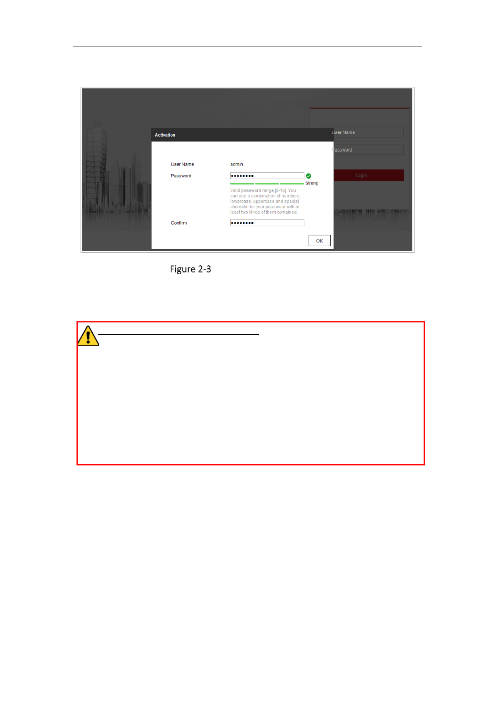
Acvaon via Web Browser
3. Create and input a password into the password eld.
A password with user name in it is not allowed.
STRONG PASSWORD RECOMMENDED–We highly recommend you create a
strong password of your own choosing (using a minimum of 8 characters,
including at least three of the following categories: upper case leers, lower
case leers, numbers, and special characters) in order to increase the security
of your product. And we recommend you reset your password regularly,
especially in the high security system, resetng the password monthly or
weekly can beer protect your product.
4. Conrm the password.
5. Click to save the password and enter the live view interface.OK
Acvaon via SADP Soware
SADP soware is used for detecng the online device, acvang the camera, and
resetng the password.
Get the SADP soware from the supplied disk or the ocial website, and install the
SADP according to the prompts. Follow the steps to acvate the camera.
Steps:

Network Camera User Manual
14
You can check whether the activation is completed on the popup window. If
activation failed, please make sure that the password meets the requirement and try
again.
5. Change the device IP address to the same subnet with your computer by either
modifying the IP address manually or checking the checkbox of Enable DHCP.
Modify the IP Address
6. Input the admin password and click to activate your IP address Modify
modification.
The batch IP address modification is supported by the SADP. Refer to the user manual
of SADP for details.
Activation via Client Software
The client software is versatile video management software for multiple kinds of
devices.
Get the client software from the supplied disk or the official website, and install the
software according to the prompts. Follow the steps to activate the camera.
Network Camera User Manual
15
Steps:
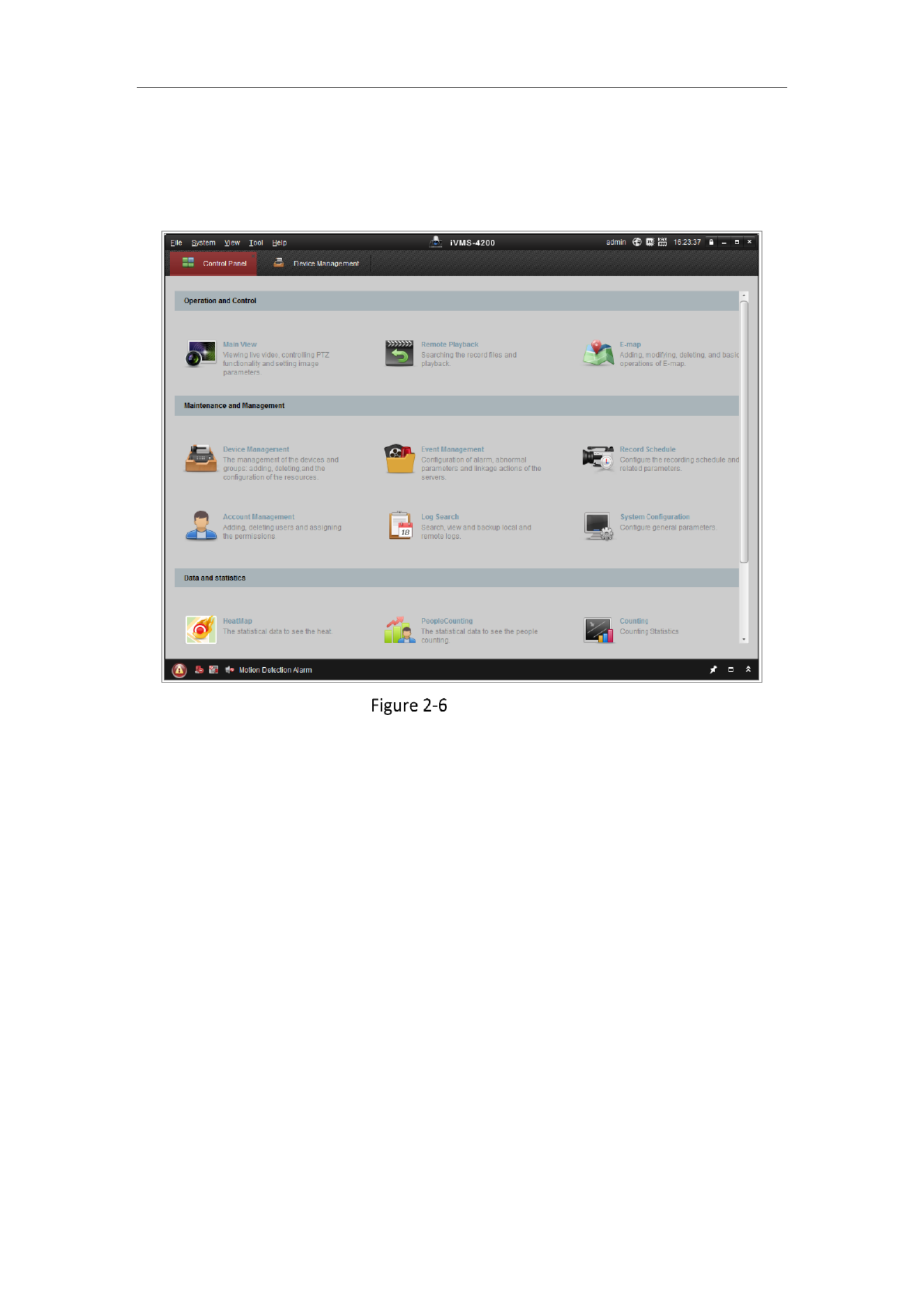
1. Run the client software and the control panel of the software pops up, as shown
in the figure below.
Control Panel
2. Click the Device Management icon to enter the Device Management interface, as
shown in the figure below.

Network Camera User Manual
16
Device Management Interface
3. Check the device status from the device list, and select an inactive device.
4. Click the Activate button to pop up the Activation interface.
5. Create a password and input the password in the password field, and confirm the
password.
A password with user name in it is not allowed.
STRONG PASSWORD RECOMMENDED–We highly recommend you
create a strong password of your own choosing (using a minimum of 8
characters, including at least three of the following categories: upper
case letters, lower case letters, numbers, and special characters) in order
to increase the security of your product. We recommend you reset your
password regularly, especially in the high security system, resetting the
password monthly or weekly can better protect your product.

Network Camera User Manual
17
Activation Interface (Client Software)
6. Click button to start activation.OK
7. Click the Modify Netinfo button to pop up the Network Parameter Modification
interface, as shown in the figure below.
Modifying the Network Parameters
8. Change the device IP address to the same subnet with your computer by either
modifying the IP address manually or checking the checkbox of Enable DHCP.
9. Input the password to activate your IP address modification.
Network Camera User Manual
19
5. Visit the network camera through a web browser or the client soware over the
internet.
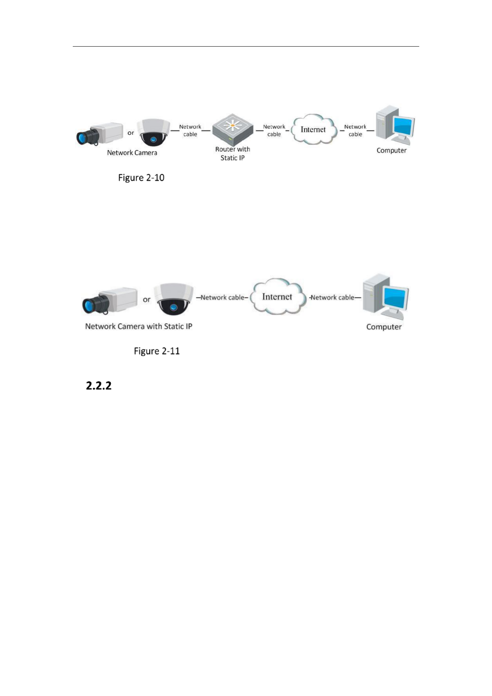
Accessing the Camera through Router with Stac IP
Connecting the network camera with static IP directly
You can also save the stac IP in the camera and directly connect it to the internet
without using a router. Refer to Secon 2.1.2 for detailed IP address conguraon of
the network camera.
Accessing the Camera with Stac IP Directly
Dynamic IP Connection
Before you start:
Please apply a dynamic IP from an ISP. With the dynamic IP address, you can connect
the network camera a modem or a router.to
Connecting the network camera via a router
Steps:
1. Connect the network camera to the router.
2. In the camera, assign a LAN IP address, the subnet mask and the gateway. Refer
to Secon 2.1.2 for detailed IP address conguraon of the network camera.
3. In the router, set the PPPoE user name, password and conrm the password.
4. Set port mapping. The steps for port mapping vary E.g. 80, 8000, and 554 ports.
depending on dierent routers. Please call the router manufacturer for assistance

Network Camera User Manual
21
1. Apply a domain name from a domain name provider.
2. Configure the DDNS settings in the interface of the network DDNS Settings
camera. Refer to Section 6.1.2 Conguring DDNS Sengs for detailed
configuration.
3. Visit the camera via the applied domain name.

Network Camera User Manual
22
Chapter 3 Access to the Network
Camera
Accessing by Web Browsers
Note:
For certain camera models, HTTPS is enabled by default and the camera creates an
unsigned cercate automacally. When you access to the camera the rst me, the
web browser prompts a nocaon about the cercate issue.
To cancel the nocaon, install a signed-cercate to the camera. For detailed
operaon, see 6.2.4 HTTPS Sengs.
Steps:
1. Open the web browser.
2. In the browser address bar, input the IP address of the network camera, and press
the key to enter the login interface.Enter
Note:
The default IP address is 192.168.1.64. You are recommended to change the IP
address to the same subnet with your computer.
3. Input the user name and password and click . Login
The admin user should congure the device accounts and user/operator
permissions properly. Delete the unnecessary accounts and user/operator
permissions.
Note:
The IP address gets locked if the admin user performs 7 failed password attempts
(5 attempts for the user/operator).

Network Camera User Manual
23
Login Interface
4. Click . Login
5. (Oponal) Install the plug-in before viewing the live video and operang the
camera. Follow the installaon prompts to install the plug-in
Note:
If you are using Google Chrome 45 and its above version or Mozilla Firefox 52 and
its above version, plug-in installaon is not required. But Picture Playback and
funcons are hidden. To use menoned funcon via web browser, change to their
lower version, or change to Internet Explorer 8.0 and above version.
Accessing by Client Soware
The product CD contains the iVMS 4200 client soware You can view the live video -.
and manage the camera with the soware.
Follow the installaon prompts to install the soware. The control panel and live
view interface of -iVMS 4200 client soware are shown as below.

Network Camera User Manual
24
iVMS 4200 Control Panel-
iVMS 4200 Main View-
Network Camera User Manual
25
Chapter 4 Live View
Live View Page
Purpose:
The live view page allows you to view the real-me video, capture images, realize
PTZ control, set/call presets and congure video parameters.
L in the network camera to enter the live view page, or you can click on og Live View
the menu bar of the main page to enter the live view page.
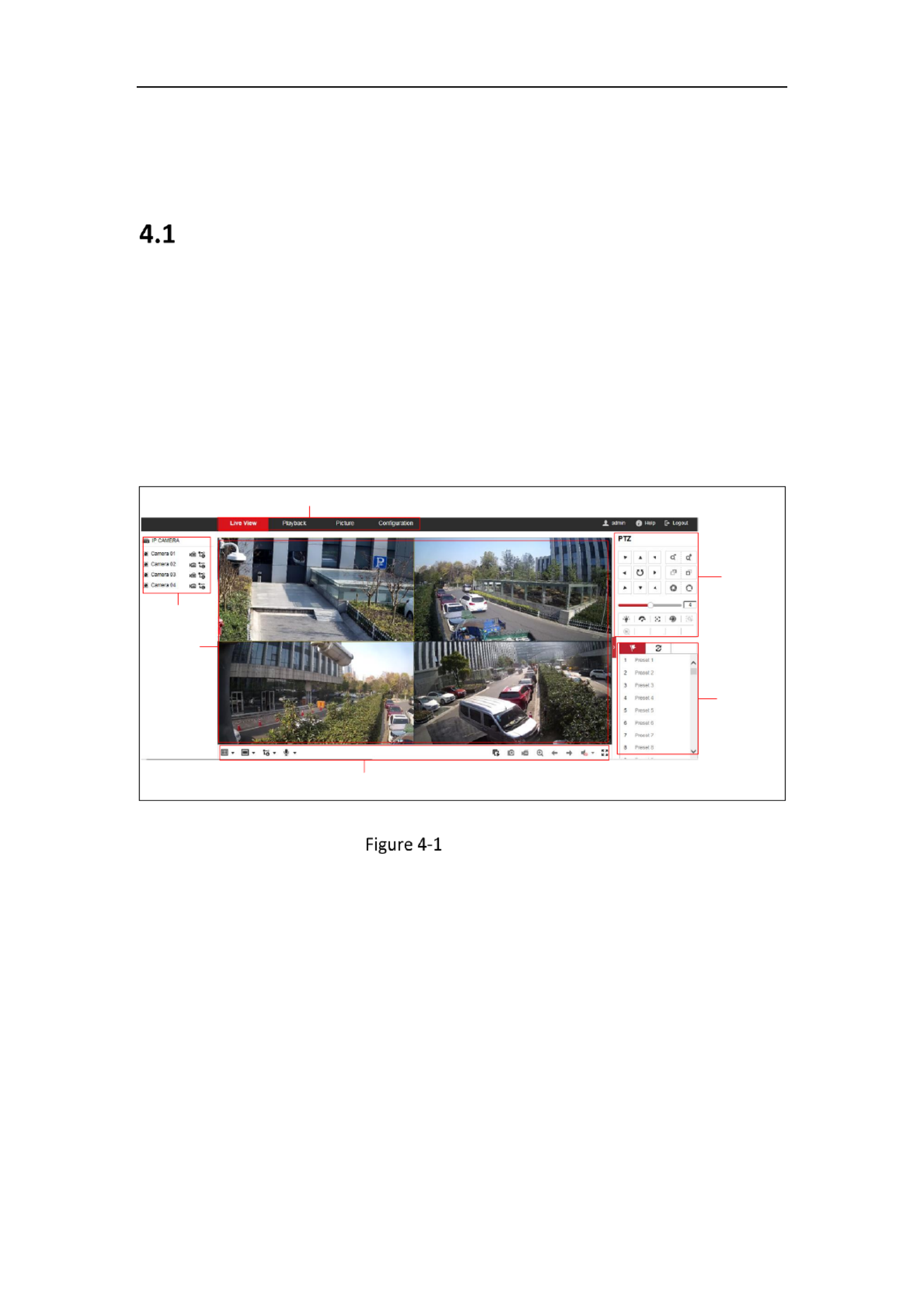
Descripons of the live view page:
Toolbar
Live View
Window
Menu Bar
PTZ Control
Panel
Preset/Patrol
Sengs
Channel
Live View Page
Menu Bar:
Click each tab to enter Live View, Playback, Picture, and Conguraon page
respecvely.
Live View Window:
Display the live video.
Toolbar:
Toolbar allows you to adjust the live view window size the stream type, and the ,
plug- s. It also allows you to process the oin peraons on the live view page, e.g.,
start/stop live view, capture, record, audio on/o, two-way audio, start/stop digital

Network Camera User Manual
26
zoom, etc.
For IE (Internet Explorer) users, plug-ins webcomponents and quick me are as
selectable. And for Non IE users, webcomponents, quick me, VLC or MJPEG are -
selectable if they are supported by the web browser.
Note:
If you are using Google Chrome 45 and its above version or Mozilla Firefox 52 and its
above version, plug-in installation is not required. But Picture Playback and funcons
are hidden. To use menoned funcon via web browser, change to their lower
version, or change to Internet Explorer 8.0 and its above version.
PTZ Control:
Perform panning, lng and zooming acons of the camera. Control the light and the
wiper (only available for cameras supporng PTZ funcon).
Preset/Patrol Sengs :
Set/call/delete the presets or patrols for PTZ cameras.
Starng Live View
In the live view window as shown in Figure 4 2, click - on the toolbar to start the
live view of the camera.
Live View Toolbar
Table 4-1 Descripons of the Toolbar
Icon
Descripon
/
Start/Stop all live view.
The window size is 4:3.
The window size is 16:9.
/
The original widow size or original rao.
Self-adapve window size.
, ,
The window division 1x1, 2x2, or 3x3.
, , , etc.
Live view with the dierent video streams.
Supported video streams vary according to camera models.

Network Camera User Manual
28
WDR: The WDR (Wide Dynamic Range) function helps the camera
provide clear images even under back light circumstances. When there
are both very bright and very dark areas simultaneously in the field of
view, WDR balances the brightness level of the whole image and provide
clear images with details. You can enable or disable the WDR function
and set the level.
HLC: High Light Compensation makes the camera identify and suppress
the strong light sources that usually flare across a scene. This makes it
possible to see the detail of the image that would normally be hidden.
OSD (On Screen Display)
Set text information displayed on screen. Alignment adjustment is available
for Text Overlay. Save the settings after configuration.
Video/Audio
Resolution and Max. Bit rate are adjustable. Click to change
stream.
Operating PTZ Control
Purpose:
In the live view interface, you can use the PTZ control buttons to realize
pan/tilt/zoom control of the camera.
Note: To realize PTZ control, the camera connected to the network must support the
PTZ function or have a pan/tilt unit installed to the camera. Please properly set the
PTZ parameters on RS485 settings page referring to Section 5.2.4 RS485 Settings.
PTZ Control Panel
On the live view page, click next to the right side of the live view window to show
the PTZ control panel and click to hide it.
Click the direction buttons to control the pan/tilt movements.
Network Camera User Manual
30
Setting/Calling a Preset
Setting a Preset:
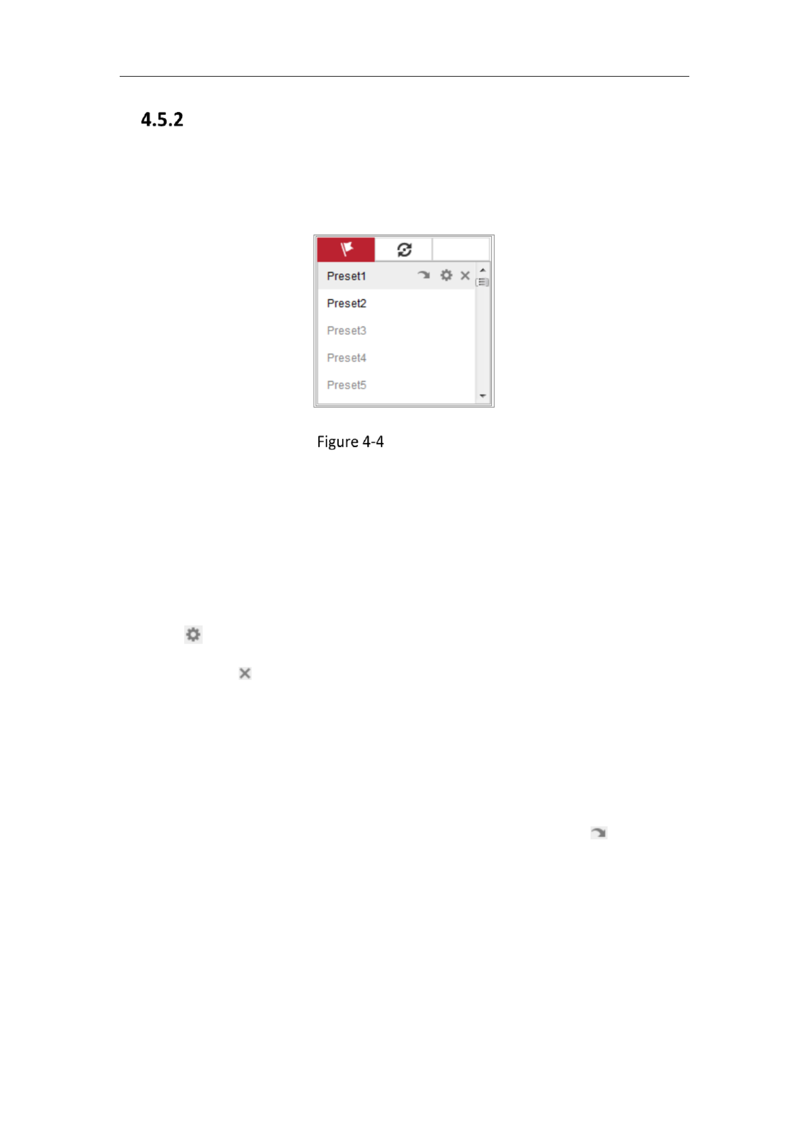
3. In the PTZ control panel, select a preset number from the preset list.
Setting a Preset
4. Use the PTZ control buttons to move the lens the desired position. to
• Pan the camera to the right or left.
• Tilt the camera up or down.
• Zoom in or out.
• Refocus the lens.
5. Click to finish the setting of the current preset.
6. You can click to delete the preset.
Calling a Preset:
This feature enables the camera to point to a specified preset scene manually or
when an event takes place.
For the defined preset, you can call it at any time to the desired preset scene.
In the PTZ control panel, select a defined preset from the list and click to call the
preset.
Or you can place the mouse on the presets interface, and call the preset by typing
the preset No. to call the corresponding presets.
Network Camera User Manual
31
Calling a Preset
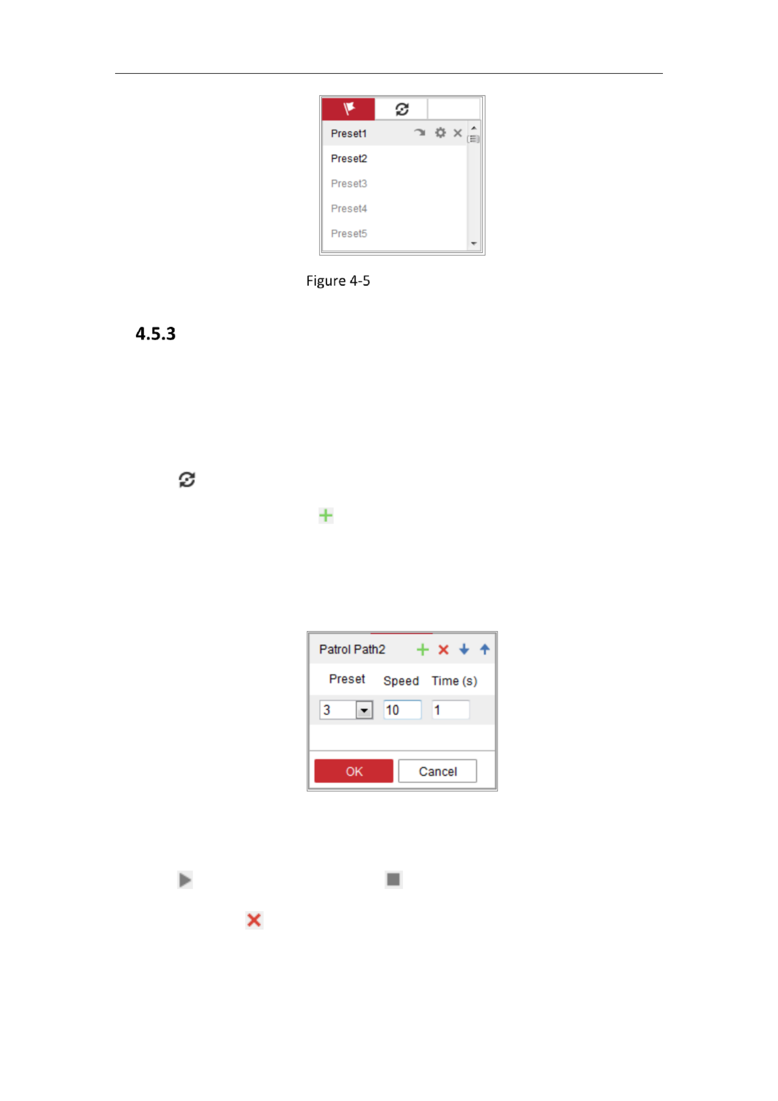
Setting/Calling a Patrol
Note:
No less than 2 presets have to be configured before you set a patrol.
Steps:
1. Click to enter the patrol configuration interface.
2. Select a path No., and click to add the configured presets.
3. Select the preset, and input the patrol duration and patrol speed.
4. Click OK to save the first preset.
5. Follow the steps above to add the other presets.
Figure 4-6 Add Patrol Path
6. Click to save a patrol. OK
7. Click to start the patrol, and click to stop it.
8. (Optional) Click to delete a patrol.

Network Camera User Manual
32
Chapter 5 Network Camera
Configuration
Configuring Local Parameters
Purpose:
The local configuration refers to the parameters of the live view, record files and
captured pictures. The record files and captured pictures are the ones you record and
capture using the web browser and thus the saving paths of them are on the PC
running the browser.
Steps:
1. Enter the Local Configuration interface: Configuration Local > .
Local Configuration Interface
2. Configure the following settings:

Network Camera User Manual
33
Live View Parameters: Set the protocol type and live view performance.
Protocol Type: TCP, UDP, MULTICAST and HTTP are selectable.
TCP: Ensures complete delivery of streaming data and better video quality,
yet the real time transmission will be affected.-
UDP: Provides real time audio and video streams.-
HTTP: Allows the same quality as of TCP without setting specific ports for
streaming under some network environments.
MULTICAST: It’s recommended to select MCAST type when using the
Multicast function. For detailed information about Multicast, refer to Section
7.1.1 Configuring TCP/IP Settings.
Play Performance: Set the play performance to Shortest Delay, Balanced or
Fluent.
Rules: It refers to the rules on your local browser, select enable or disable to
display or not display the colored marks when the motion detection, face
detection, or intrusion detection is triggered. E.g., enabled as the rules are,
and the face detection is enabled as well, when a face is detected, it will be
marked with a green rectangle on the live view.
Display POS Information: Enable the function, feature information of the
detected target is dynamically displayed near the target in the live image.
The feature information of different functions are different. For example, ID
and waiting time for Queue Management, height for People Counting, etc.
Note:
Display POS Information is only available for certain camera models.
Auto Start Live View: Enable the function to start live view automatically
when accessing the camera.
Image Format: Choose the image format for picture capture.
Record File Settings: Set the saving path of the recorded video files. Valid for the
record files you recorded with the web browser.
Record File Size: Select the packed size of the manually recorded and
downloaded video files to 256M, 512M or 1G. After the selection, the

Network Camera User Manual
36
Time Settings
2. Select the Time Zone of your location from the drop down menu.-
3. Configure the NTP settings.
(1) Click to enable the function. NTP
(2) Configure the following settings:
Server Address: IP address of NTP server.
NTP Port: Port of NTP server.
Interval: The time interval between the two synchronizing actions with NTP
server.
(3) (Optional) You can click the Test button to test the time synchronization
function via NTP server.
Time Sync by NTP Server
Note: If the camera is connected to a public network, you should use a NTP server

Network Camera User Manual
38
1. Enter RS232 Port Setting interface: Configuration System System Settings> > >
RS232.
2. Configure the Baud Rate, Data Bit, Stop Bit, Parity, Flow Control, and Usage.
RS232 Settings
Note: If you want to connect the camera by the RS232 port, the parameters of the
RS232 should be exactly the same with the parameters you configured here.
3. Click Save to save the settings.
Configuring RS485 Settings
Purpose:
The RS485 serial port is used to control the PTZ of the camera. The configuring of the
PTZ parameters should be done before you control the PTZ unit.
Steps:
1. Enter RS 485 Port Setting interface: - Configuration System System Settings> > >
RS485.

Network Camera User Manual
39
RS- 485 Settings
2. Set the RS485 parameters and click Save to save the settings.
By default, the Baud Rate is set as 9600 bps, the Data Bit is 8, the stop bit is 1 and
the Parity and Flow Control is None.
Note: The Baud Rate, PTZ Protocol and PTZ Address parameters should be exactly the
same as the PTZ camera parameters.
Conguring DST Seings
Purpose:
Daylight Saving Time (DST) is a way of making better use of the natural daylight by
setting your clock forward one hour during the summer months, and back again in
the fall.
Configure the DST according to your actual demand.
Steps:
1. Enter the DST configuration interface.
Conguraon System System Setngs DST> > >

Network Camera User Manual
40
DST Sengs
2. Select the start me and the end me.
3. Select the DST Bias.
4. Click Save to acvate the sengs.
Conguring Image Stching
Purpose:
You can switch the video output mode for the camera according to your actual
demand. There are four video output modes, including Panorama + ePTZ, Panorama,
Original and Divided Panorama.
Steps:
1. Enter the Image Stching conguraon interface.
Conguraon System System Setngs Image Stching> > >
Image Stching Setngs

Network Camera User Manual
41
2. Select the desired video output mode.
Video Output Mode: Set the desired output mode as required.
Panorama + ePTZ: One stched panoramic image (8MP) and mulple channels
ePTZ images. Channel 01 is the 8MP panoramic image, and channel 02 and the
subsequent channels are ePTZ images. You can set the number of the channels
for the ePTZ image. Ten channels are available. For example, if you set the
number of the ePTZ channels to 6, then the live view is seven channels: one 8MP
panoramic image and six ePTZ images.
Panorama: One stched panoramic image (32MP) and the panoramic image
output from 1 or 3 encoder track.
Original: Four independent original images (8MP). Take the pendent mounng as
an example, when facing the camera lens, the channel order is 01 ~ 04 from right
to le.
Divided Panorama: The stched 32MP panoramic image is divided into four 8MP
images.
Encoder Track: Stream can be divided into several tracks in order to make up for
the deciency of decoder. 1 track and 3 tracks are selectable, and it is
recommended to select 3, when the decoder is in poor performance.
Notes:
• The ePTZ channels support patrol funcon. You can click on the live
view image to enable or disable the patrol funcon for ePTZ channels.
• You can set the image sengs for each channel in the original mode.
• Only the main stream of 2400W and 1600W panorama camera support the
encoder track.
3. Enter the best stching distance.
Best Stching Distance: The distance between the lens and the stching surface
you set for the best stching image quality. The further the distance is, the worse
the stching image quality is.
For example, if you set the best stching distance to 30 meters, the stching
image of 30 meters far from the lens is the best quality. The stching image of 20
or 40 meters far from the lens is not good and the image of 10 or 50 meters far

Network Camera User Manual
42
from the lens is the worst.
Notes:
For the Original mode, Best Stching Distance are not supported.
4. Click Save.
Open Source Soware License
Informaon about the open source soware that applies to the IP camera can be
checked if required. Go to Conguraon > System Sengs > About.
Open Source Soware Licenses
Maintenance
5.3.1 Upgrade & Maintenance
Purpose:
The upgrade & maintenance interface allows you to process the operaons, including
reboot, partly restore, restore to default, export/import the conguraon les, and
upgrade the device.
Enter the Maintenance interface: Conguraon System > > Maintenance Upgrade >
& Maintenance.
Reboot: Restart the device.
Restore: Reset all the parameters, except the IP parameters and user
informaon, to the default setngs.
Default: Restore all the parameters to the factory default.
Notes:
• Aer restoring the default setngs, the IP address is also restored to the

Network Camera User Manual
43
default IP address, please be careful for this acon.
• For camera that supports Wi Fi, wireless dial, or wlan funcon, -Restore
acon does not restore the related setngs of menoned funcons to
default.
Informaon Export
Device Parameters: click to export the current conguraon le of the camera.
This operaon requires admin password to proceed.
For the exported le, you also have to create an encrypon password. The
encrypon password is required when you import the le to other cameras.
Diagnose Informaon: click to download log and system informaon.
Import Cong. File
Conguraon le is used for the batch conguraon of the camera s.
Steps:
1. Click to select the saved conguraon le.Browse
2. Click and input encrypon password to start imporng conguraon Import
le.
Note: You need to reboot the camera aer imporng conguraon le.
Upgrade: Upgrade the device to a certain version.
Steps:
1. Select rmware or rmware directory to locate the upgrade le.
Firmware: Locate the exact path of the upgrade le.
Firmware Directory: Only the directory the upgrade le belongs to is
required.
2. Click to select the local upgrade le and then click Browse Upgrade to start
remote upgrade.
Note: e upgrading process will take 1 to 10 minutes. Please don't disconnect Th
power of the camera during the process, and the camera reboots automacally
aer upgrade.

Network Camera User Manual
44
Log
Purpose:
The operaon, alarm, excepon and informaon of the camera can be stored in log
les. You can also export the log les on your demand.
Before you start:
Please congure network storage for the camera or insert a SD card in the camera.
Steps:
1. Enter log searching interface: Conguraon System Maintenance Log > > > .
Log Searching Interface
2. Set the log search condions to specify the search, including the Major Type,
Minor Type, Start Time and End Time.
3. Click to search log les. The matched log les will be displayed on the log Search
list interface.

Network Camera User Manual
45
Log Searching
4. To export the log les, click to save the log les.Export
System Service
Purpose:
System service sengs refer to the hardware service the camera supports.
Supported funcons vary according to the dierent cameras. For the cameras
support IR Light, ABF (Auto Back Focus), Auto Defog, or Status LED, you can select to
enable or disable the corresponding service according to the actual demands.
ABF: When ABF funcon is enabled, you can click on PTZ control panel to realize
auxiliary focus.
Third Stream: For some models, third stream is not enabled by default. Check Enable
Third Stream enable the funcon.to
Enable Third Stream

Network Camera User Manual
46
Security Setngs
Congure the parameters, including Authencaon, IP Address Filter, and Security
Service from security interface.
Authencaon
Purpose:
You can specically secure the stream data of live view.
Steps:
1. Enter the Authencaon interface: Conguration System Security> > >
Authencaon.
Authencaon
2. Set up authencaon method for RTSP authencaon and WEB authencaon.
Cauon:
Digest is the recommended authencaon method for better data security. You
must be aware of the risk if you adopt basic as the authencaon method.
3. Click Save to save the setngs.
IP Address Filter
Purpose:
This funcon makes it possible for access control.
Steps:
1. Enter the IP Address Filter interface: Conguraon System Security IP > > >
Address Filter

Network Camera User Manual
47
IP Address Filter Interface
2. Check the checkbox of .Enable IP Address Filter
3. Select the type of IP Address Filter in the drop down list, and -Forbidden Allowed
are selectable.
4. Set the IP Address Filter list.
Add an IP Address
Steps:
(1) Click the to add an IP.Add
(2) Input the IP Adreess.
Add an IP
(3) Click the to nish adding.OK
Modify an IP Address
Steps:
(1) - Le click an IP address from lter list and click .Modify
(2) Modify the IP address in the text led.

Network Camera User Manual
48
Modify an IP
(3) Click the to nish modifying.OK
Delete an IP Address or IP Addresses.
Select the IP address(es) and click .Delete
5. Click Save to save the setngs.
Security Service
To enable the remote login, and improve the data communicaon security, the
camera provides the security service for beer user experience.
Steps:
1. Enter the security service conguraon interface: Conguration System > >
Security Security Service > .
Security Service
2. Check the checkbox of .Enable Illegal Login Lock
Illegal Login Lock: it is used to limit the user login attempts. Login aempt from
the IP address is rejected if admin user performs 7 failed user name/password
attempts (5 mes for the operator/user).
Note: If the IP address is rejected, you can try to login the device aer 30
minutes.
Network Camera User Manual
49
User Management
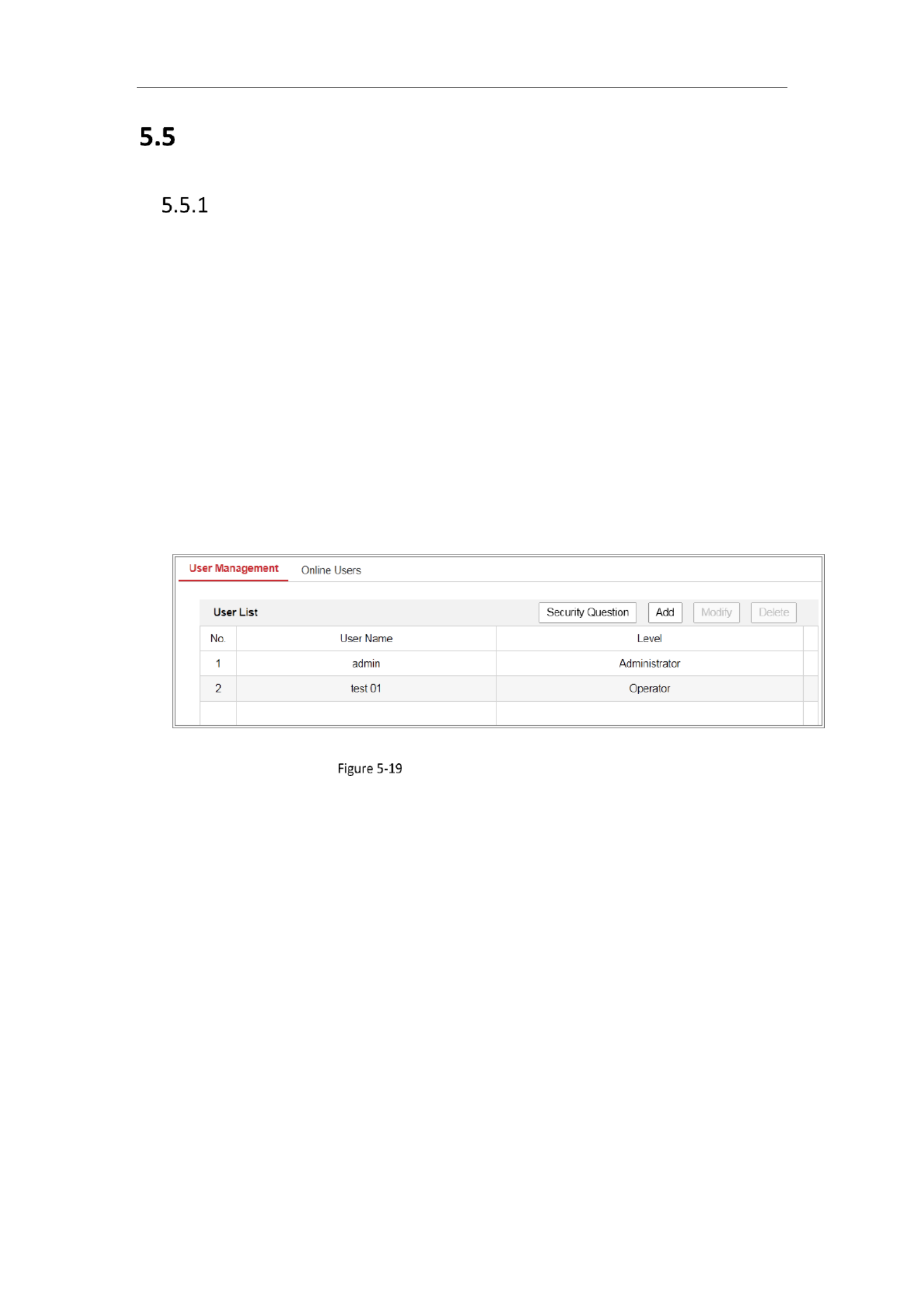
User Management
As Administrator
The admin user can add, delete or modify user accounts, and grant them
dierent permissions. We highly recommend you manage the user accounts and
permissions properly.
Enter the User Management interface: Conguraon System User > >
Management
Note:
Admin password if required for adding and modifying a user account.
User Management Interface
Adding a User
The user has all permissions by default and can create/modify/delete admin
other accounts.
The user cannot be deleted and you can only change the password.admin admin
Steps:
1. Click to add a user.Add
2. Input the Admin Password User Name Level Password., , select and input
Notes:
● Up to 31 user accounts can be created.
● Users of dierent levels own dierent default permissions. Operator and
user are selectable.

Network Camera User Manual
50
STRONG PASSWORD RECOMMENDED–We highly recommend you create
a strong password of your own choosing (using a minimum of 8 characters,
including at least three of the following categories: upper case leers,
lower case letters, numbers, and special characters) in order to increase
the security of your product. And we recommend you reset your password
regularly, especially in the high security system, resetng the password
monthly or weekly can better protect your product.
3. You can check or uncheck the permissions for the new user.
4. Click to nish the user addion.OK
Modifying a User
Steps:
1. Le click to select the user from the list and click -Modify.
2. Modify the , and User Name Level Password.
STRONG PASSWORD RECOMMENDED–We highly recommend you create a
strong password of your own choosing (using a minimum of 8 characters,
including at least three of the following categories: upper case letters, lower
case leers, numbers, and special characters) in order to increase the
security of your product. And we recommend you reset your password
regularly, especially in the high security system, reseng the password
monthly or weekly can better protect your product.
3. You can check or uncheck the permissions.
4. Click to nish the user modicaon.OK
Deleng a User
Steps:
1. Click to select the user you want to delete and click .Delete
2. Click on the pop up dialogue box to conrm the deleon.OK -
As Operator or User
Operator or user can modify password. Old password is required for this acon.

Network Camera User Manual
51
Security Question
Purpose:
Security queson is used to reset the admin password when admin user forgets the
password.
Set Security Queson:
You can set the security quesons during camera acvaon. Or you can set the
funcon at user management interface.
Security queson seng is not cleared when you restore the camera (not to default).
Steps:
1. Enter seng interface:
Conguraon > System > User Management > User Management
2. Click Security Queson.
3. Input correct admin password.
4. Select quesons and input answers.
5. Click to save the sengs. OK
Reset Admin Password:
Before you start:
The PC used to reset password and the camera should belong to the same IP address
segment of the same LAN.
Steps:
1. Enter login interface via web browser.
2. Click Forget Password.
3. Answer security queson.
4. Create new password.
Note:
User IP address is locked for 30 minutes aer 7 failed attempts of answering security
quesons.

Network Camera User Manual
52
Online Users
Purpose:
You can see the current users who are vising the device through this interface. User
informaon, such as user name, level, IP address, and operaon me, is displayed in
the User List.
Click Refresh to refresh the list.
View the Online Users
Chapter 6 Network Settings
Purpose:
Follow the instrucons in this chapter to congure the basic sengs and advanced
sengs.
Configuring Basic Settings
Purpose:
You can congure the parameters, including TCP/IP, DDNS, PPPoE, Port, and NAT, etc.,
by following the instrucons in this secon.
Configuring TCP/IP Settings
Purpose:
TCP/IP setngs must be properly congured before you operate the camera over
network. The camera supports both the IPv4 and IPv6. Both versions can be
congured simultaneously without conicng to each other, and at least one IP

Network Camera User Manual
53
version should be configured.
Steps:
1. Enter TCP/IP Settings interface: Configuration > Network > Basic Settings >
TCP/IP
TCP/IP Settings
2. Configure the basic network settings, including the NIC Type, IPv4 or IPv6 Address,
IPv4 or IPv6 Subnet Mask, IPv4 or IPv6 Default Gateway, MTU settings and
Multicast Address.
3. (Optional) Check the checkbox of , and then the online Enable Multicast Discovery
network camera can be automatically detected by client software via private
multicast protocol in the LAN.
4. Configure the DNS server. Input the preferred DNS server, and alternate DNS
server.
5. Click Save to save the above settings.

Network Camera User Manual
55
Figure 6-2 DynDNS Settings
NO-IP:
Steps:
(1) Choose the DDNS Type as NO-IP.
Figure 6-3 NO-IP DNS Settings
(2) Enter the Server Address as www.noip.com
(3) Enter the Domain name you registered.
(4) Enter the User Name and Password.
(5) Click and then you can view the camera with the domain name. Save
Note: Reboot the device to make the settings take effect.

Network Camera User Manual
56
Configuring PPPoE Settings
Steps:
1. Enter the PPPoE Settings interface: Configuration > Network > Basic Settings >
PPPoE
PPPoE Settings
2. Check the checkbox to enable this feature. Enable PPPoE
3. Enter , , and password for PPPoE access. User Name Password Confirm
Note: The User Name and Password should be assigned by your ISP.
For your privacy and to better protect your system against security risks, we
strongly recommend the use of strong passwords for all functions and network
devices. The password should be something of your own choosing (using a
minimum of 8 characters, including at least three of the following categories:
upper case letters, lower case letters, numbers and special characters) in order to
increase the security of your product.
Proper configuration of all passwords and other security settings is the
responsibility of the installer and/or end user.-
4. Click Save to save and exit the interface.
Note: A reboot is required for the settings to take effect.
Configuring Port Settings
Purpose:
Network Camera User Manual
57
You can set the port No. of the camera, e.g., HTTP port, RTSP port and HTTPS port.
Steps:
1. Enter the Port Settings interface, Configuration > Network > Basic Settings >
Port
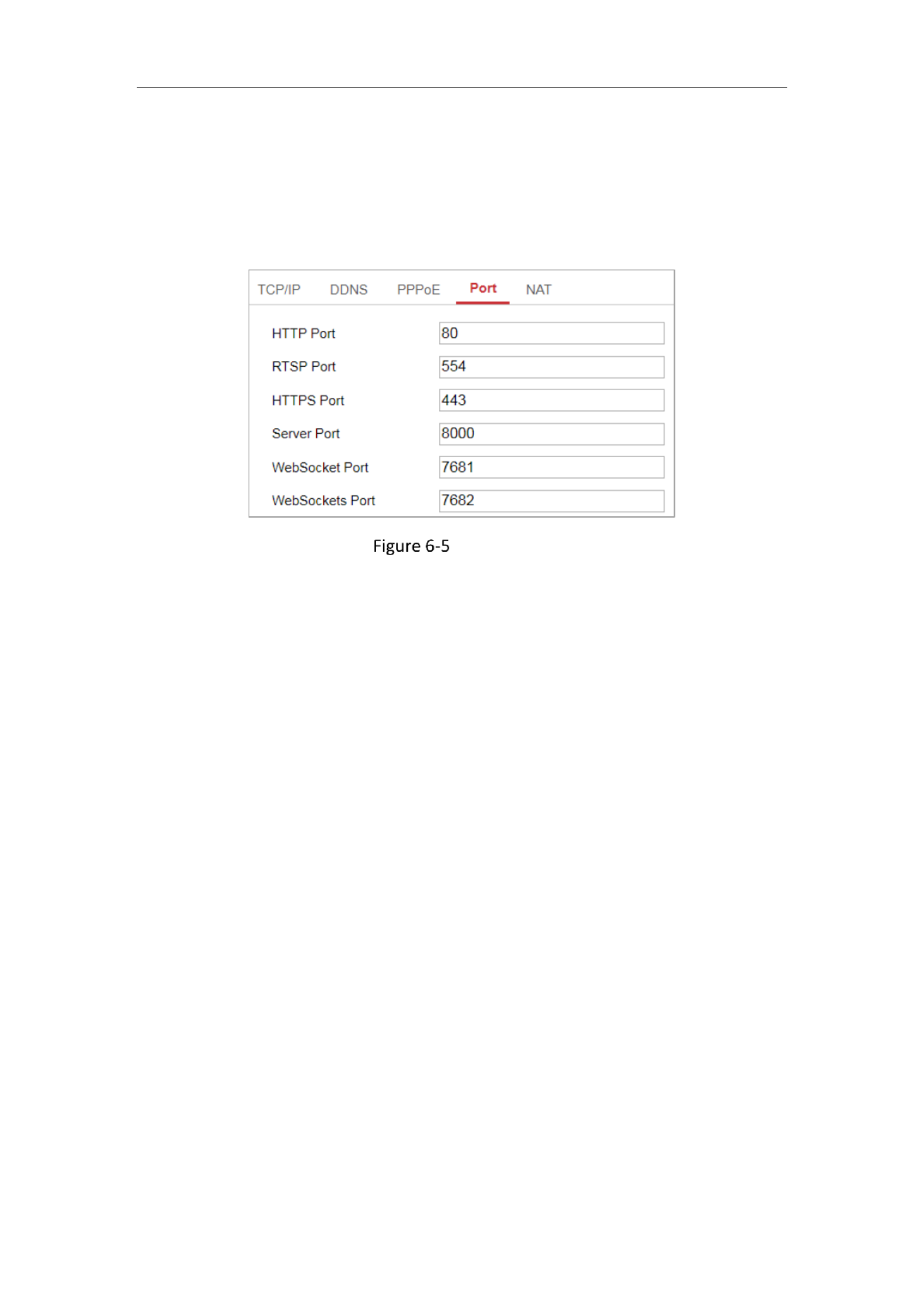
Port Settings
2. Set the ports of the camera.
HTTP Port: The default port number is 80, and it can be changed to any port No.
which is not occupied.
RTSP Port: The default port number is 554 and it can be changed to any port No.
ranges from 1 to 65535.
HTTPS Port: The default port number is 443, and it can be changed to any port
No. which is not occupied.
Server Port: The default server port number is 8000, and it can be changed to
any port No. ranges from 2000 to 65535.
Note:
When you use client software to visit the camera and you have changed the
server port number, you have to input the correct server port number in login
interface to access to the camera.
WebSocket Port: The default port number is 7681. It can be changed to any port
No. ranges from 1 to 65535.
WebSockets Port: The default server port number is 7682. It can be changed to
any port No. ranges from 1 to 65535.

Network Camera User Manual
58
Note:
WebSocket and WebSockets protocol are used for plug in free live view. -
3. Click Save to save the settings.
Note: A reboot is required for the settings to take effect.
Configure NAT (Network Address Translation) Settings
Purpose:
NAT interface allows you to configure the UPnP™ parameters.
Universal Plug and Play (UPnP™) is a networking architecture that provides
compatibility among networking equipment, software and other hardware devices.
The UPnP protocol allows devices to connect seamlessly and to simplify the
implementation of networks in the home and corporate environments.
With the function enabled, you don’t need to configure the port mapping for each
port, and the camera is connected to the Wide Area Network via the router.
UPnP Settings
Steps:
1. Enter the NAT settings interface. Configuration > Network > Basic Settings >
NAT.
2. Check the checkbox to enable the UPnP™ function.
Note:
Only when the UPnP™ function is enabled, ports of the camera are active.
3. Choose a friendly name for the camera, or you can use the default name.

Network Camera User Manual
59
4. Select the port mapping mode. Manual and Auto are selectable.
Note:
If you select Auto, you should enable UPnP™ function on the router.
If you select Manual, you can customize the value of the external port and
complete port mapping settings on router manually.
5. Click Save to save the settings.
Configure Advanced Settings
Purpose:
You can configure the parameters, including SNMP, FTP, Email, HTTPS, QoS, 802.1x,
etc., by following the instructions in this section.
Configuring SNMP Settings
Purpose:
You can set the SNMP function to get camera status, parameters and alarm related
information, and manage the camera remotely when it is connected to the network.
Before you start:
Before setting the SNMP, please download the SNMP software and manage to
receive the camera information via SNMP port. By setting the Trap Address, the
camera can send the alarm event and exception messages to the surveillance center.
Note: The SNMP version you select should be the same as that of the SNMP software.
And you also need to use the different version according to the security level you
required. SNMP v1 provides no security and SNMP v2 requires password for access.
And SNMP v3 provides encryption and if you use the third version, HTTPS protocol
must be enabled.
For your privacy and to better protect your system against security risks, we
strongly recommend the use of strong passwords for all functions and network

Network Camera User Manual
60
devices. The password should be something of your own choosing (using a
minimum of 8 characters, including at least three of the following categories:
upper case letters, lower case letters, numbers and special characters) in order to
increase the security of your product.
Proper configuration of all passwords and other security settings is the
responsibility of the installer and/or end user.-
Steps:
1. Enter the SNMP Settings interface: Configuration > Network > Advanced
Settings > SNMP.
Network Camera User Manual
61
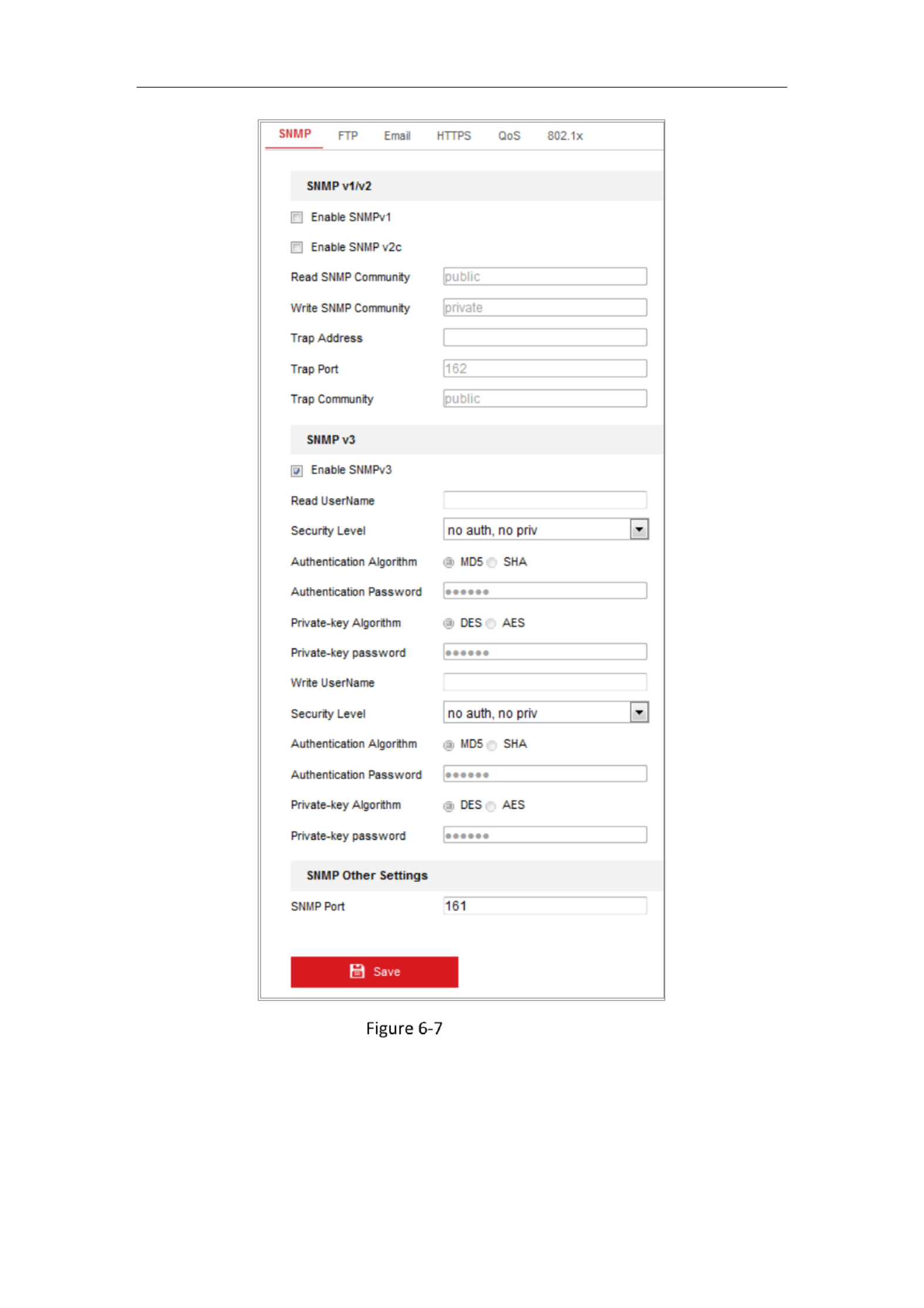
SNMP Settings
2. Check the checkbox of Enable SNMPv1, Enable SNMP v2c, Enable SNMPv3 to
enable the feature correspondingly.
3. Configure the SNMP settings.
Note: The settings of the SNMP software should be the same as the settings you
Network Camera User Manual
62
configure here.
4. Click to save and finish the settings. Save
Notes:
• A reboot is required for the settings to take effect.
• To lower the risk of information leakage, you are suggested to enable SNMP v3
instead of SNMP v1 or v2.
6.2.2 Configuring FTP Settings
Purpose:
You can configure the FTP server related information to enable the uploading of the
captured pictures to the FTP server. The captured pictures can be triggered by events
or a timing snapshot task.
Steps:
1. Enter the FTP Settings interface: Configuration > Network > Advanced Settings >
FTP.
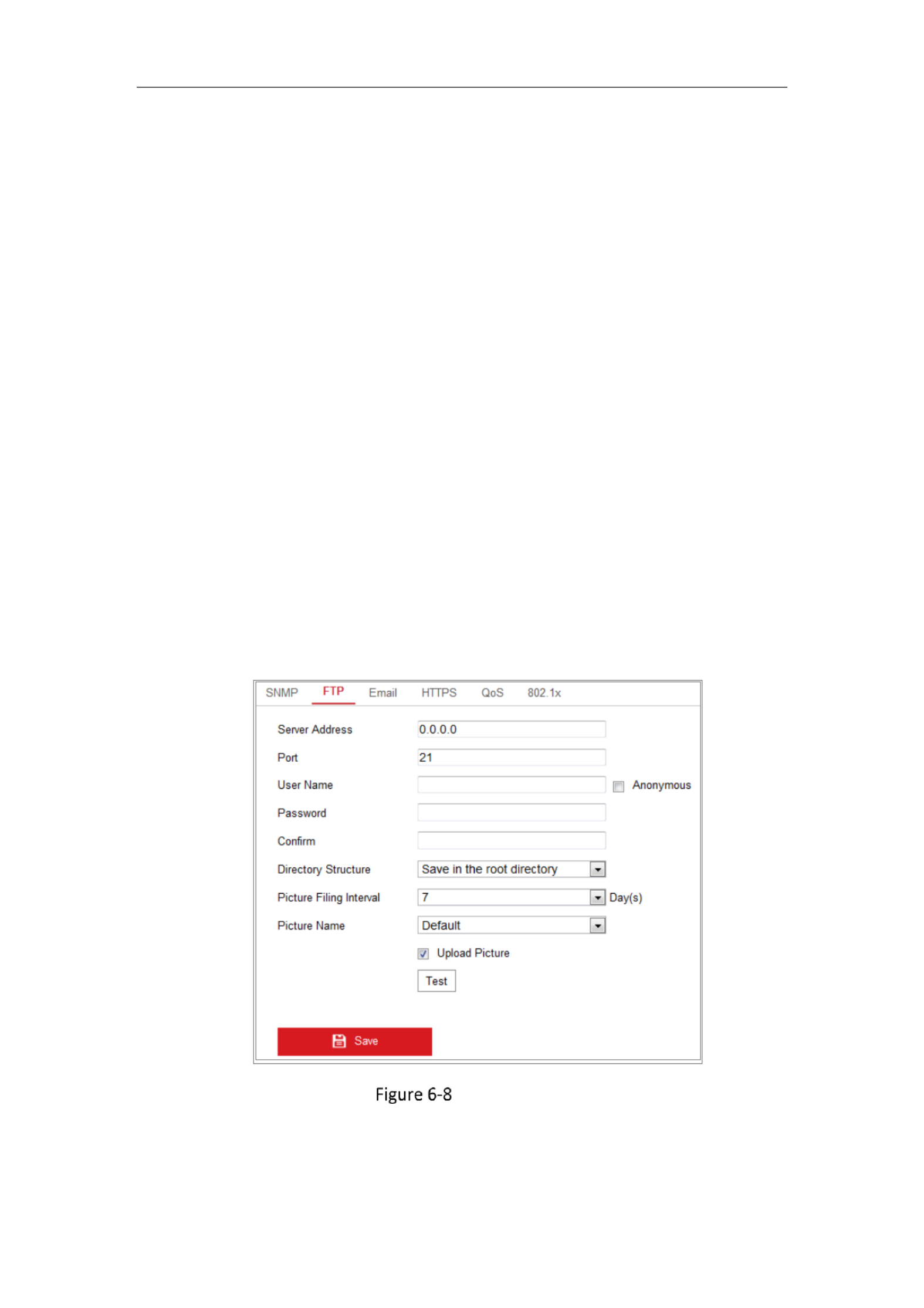
FTP Settings
2. Input the FTP address and port.
3. Configure the FTP settings; and the user name and password are required for the

Network Camera User Manual
63
FTP server login.
For your privacy and to better protect your system against security risks, we
strongly recommend the use of strong passwords for all functions and
network devices. The password should be something of your own choosing
(using a minimum of 8 characters, including at least three of the following
categories: upper case letters, lower case letters, numbers and special
characters) in order to increase the security of your product.
Proper configuration of all passwords and other security settings is the
responsibility of the installer and/or end user.-
4. Set the directory structure and picture filing interval.
Directory Directory Structure: In the field, you can select the root directory,
parent directory and child directory. When the parent directory is selected, you
have the option to use the Device Name, Device Number or Device IP for the
name of the directory; and when the Child Directory is selected, you can use the
Camera Name or Camera No. as the name of the directory.
Picture Filing Interval: For better picture management, you can set the picture
filing interval from 1 day to 30 days. Pictures captured in the same time interval
will be saved in one folder named after the beginning date and ending date of
the time interval.
Picture Name: Set the naming rule for captured picture files. You can choose
Default in the drop down list to use the default rule, that is, -
IP address_channel number_capture time_event type.jpg
(e.g., 10.11.37.189_01_20150917094425492_FACE_DETECTION.jpg).
Or you can customize it by adding a Custom Prefix to the default naming rule.
5. Check the Upload Picture checkbox to enable the function.
Upload Picture: To enable uploading the captured picture to the FTP server.
Anonymous Access to the FTP Server (in which case the user name and
password won’t be required.): AnonymousCheck the checkbox to enable the

Network Camera User Manual
64
anonymous access to the FTP server.
Note: The anonymous access function must be supported by the FTP server.
6. Click Save to save the settings.
6.2.3 Configuring Email Settings
Purpose:
The system can be configured to send an Email notification to all designated
receivers if an alarm event is detected, e.g., motion detection event, video loss,
video tampering, etc.
Before you start:
Please configure the DNS Server settings under Configuration > Network > Basic
Settings > TCP/IP before using the Email function.
Steps:
1. Enter the TCP/IP Settings (Configuration > Network > Basic Settings > TCP/IP ) to
set the IPv4 Address, IPv4 Subnet Mask, IPv4 Default Gateway and the Preferred
DNS Server.
Note: Please refer to for detailed Configuring TCP/IP SettingsSection 7.1.1
information.
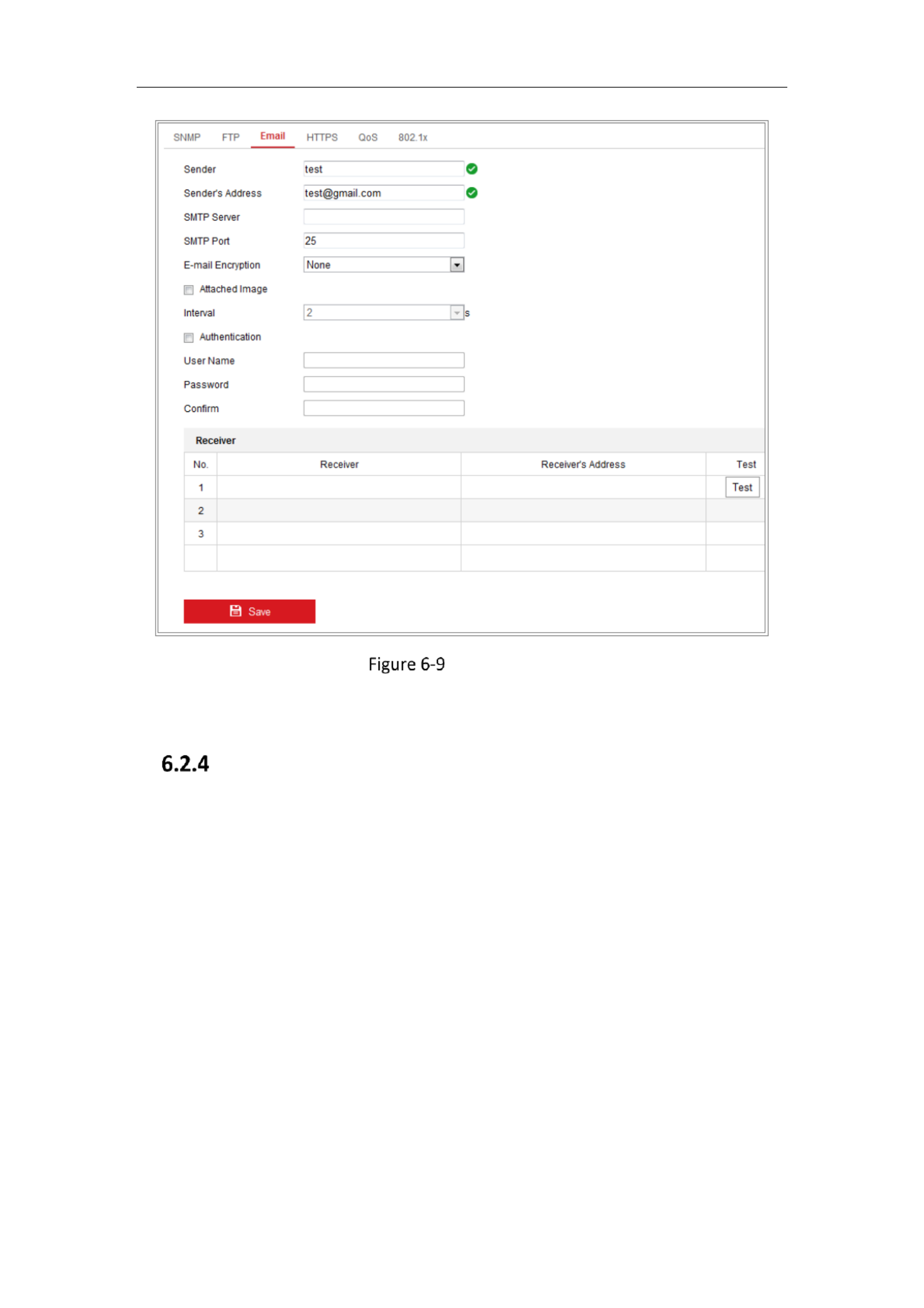
2. Enter the Email Settings interface: Configuration Network Advanced Settings > > >
Email.
3. Configure the following settings:
Sender: The name of the email sender.
Sender’s Address: The email address of the sender.
SMTP Server: IP address or host name (e.g., smtp.263xmail.com) of the SMTP
Server.
SMTP Port: The SMTP port. The default TCP/IP port for SMTP is 25 (not secured).
And the SSL SMTP port is 465.
Email Encryption: None, SSL, and TLS are selectable. When you select SSL or TLS
and disable STARTTLS, e mails will be sent after encrypted by SSL or TLS. Th- e

Network Camera User Manual
65
SMTP port should be set as 465 for this encryption method. When you select SSL
or TLS and enable STARTTLS, emails will be sent after encrypted by STARTTLS,
and the SMTP port should be set as 25.
Note: If you want to use STARTTLS, make sure that the protocol is supported by
your e mail server. If you check the Enable STARTTLS checkbox when the -
protocol is not supported by your e mail sever, your e mail will not be encrypted.- -
Attached Image: Check the checkbox of Attached Image if you want to send
emails with attached alarm images.
Interval: The interval refers to the time between two actions of sending attached
pictures.
Authentication (optional): If your email server requires authentication, check
this checkbox to use authentication to log in to this server and input the login
user name and password.
For your privacy and to better protect your system against security risks, we
strongly recommend the use of strong passwords for all functions and
network devices. The password should be something of your own choosing
(using a minimum of 8 characters, including at least three of the following
categories: upper case letters, lower case letters, numbers and special
characters) in order to increase the security of your product.
Proper configuration of all passwords and other security settings is the
responsibility of the installer and/or end user.-
The Receiver :table Select the receiver to which the email is sent. Up to 3
receivers can be configured.
Receiver: The name of the user to be notified.
Receiver’s Address: The email address of user to be notified.
Network Camera User Manual
66
Email Settings
4. Click Save to save the settings.
HTTPS Settings
Purpose:
HTTPS provides authentication of the web site and its associated web server, which
protects against Man in middle attacks.- -the-
Note:
HTTPS is enabled by default for certain camera models.
If HTTPS is enabled, the camera creates an unsigned certificate automatically.
When accessing via HTTPS, the web browser will send a prompt that installing a
signed certificate is recomme ed.nd
Steps:
1. Enter the HTTPS settings interface. Configuration > Network > Advanced

Network Camera User Manual
67
Settings > HTTPS.
2. Check to access the camera via HTTP or HTTPS protocol.Enable
HTTPS Configuration Interface
3. Create the self signed certificate or authorized certificate.-
Create Self signed Certificate-
Create the self signed certificate-
(1) Select Create Self signed Certificate- as the Installation Method.
(2) Click Create button to enter the creation interface.
(3) Enter the country, host name/IP, validity and other information.
(4) Click to save the settings. OK
Note: If you already had a certificate installed, the Create Self signed -
Certificate is grayed out.
Create the request and import the authorized certificate
(1) Select Create the certificate request first and continue the installation as

Network Camera User Manual
68
the Installation Method.
(2) Click Create button to create the certificate request. Fill in the required
information in the popup window.
(3) Click to download the certificate request and submit it to the Download
trusted certificate authority for signature.
(4) After receiving the signed valid certificate, you can import the certificate in
two ways:
a) Select Signed certificate is available, Start the installation directly. Click
Browse Install and to import the certificate to the device.
Import the Certificate (1)
b) Select Create the certificate request first and continue the installation.
Click and Browse Install to import the certificate to the device.
Import the Certificate (2)
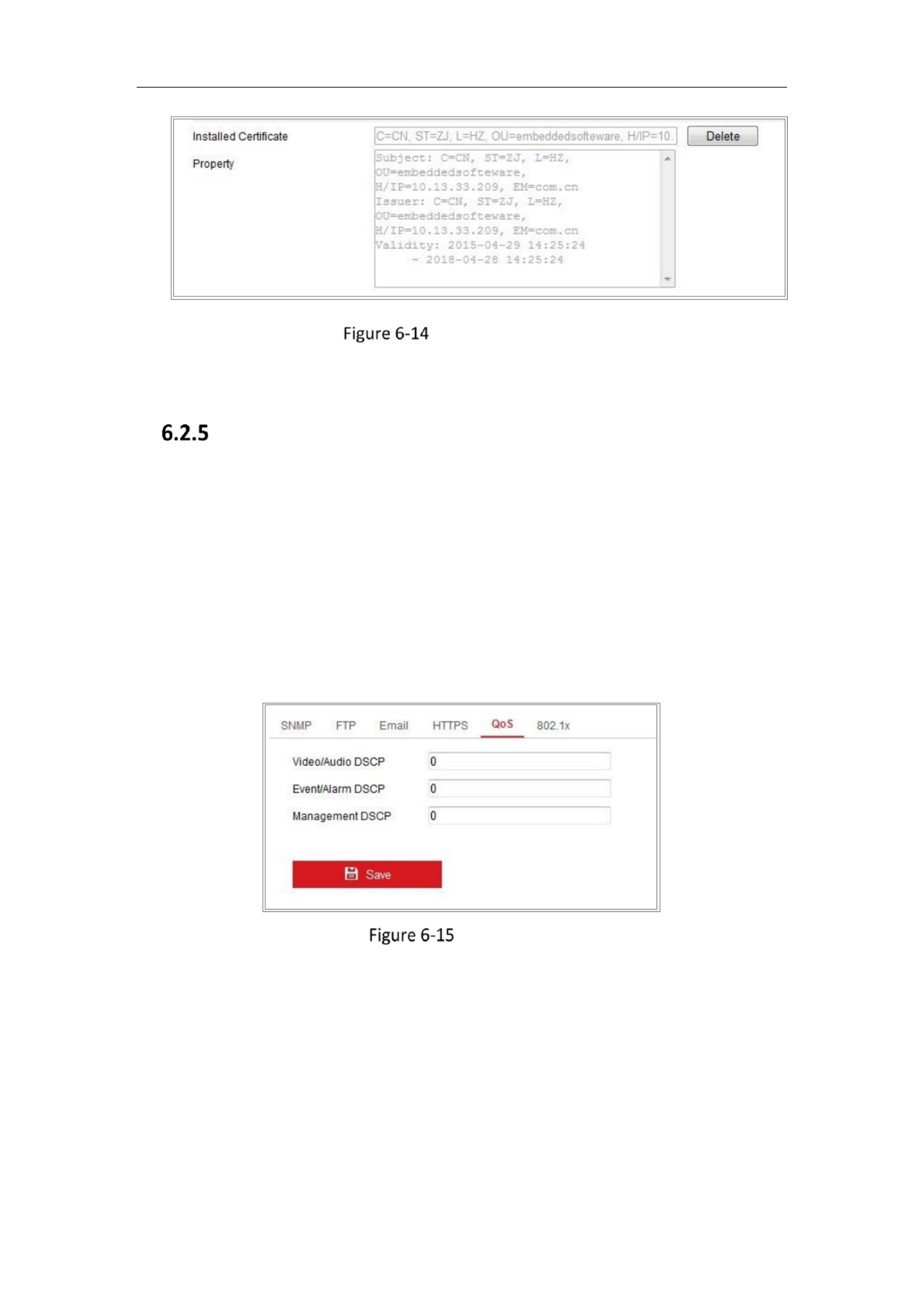
4. There will be the certificate information after your successfully creating and
installing the certificate.
Network Camera User Manual
69
Installed Certificate
5. Click the Save button to save the settings.
Configuring QoS Settings
Purpose:
QoS (Quality of Service) can help solve the network delay and network congestion by
configuring the priority of data sending.
Steps:
1. Enter the QoS Settings interface: Configuration > Network > Advanced Settings >
QoS
QoS Settings
2. Configure the QoS settings, including Video/Audio DSCP, Event/Alarm DSCP and
Management DSCP.
The valid value range of the DSCP is 0 to 63. The bigger the DSCP value is, the
higher the priority is.
Note: DSCP refers to the Differentiated Service Code Point; and the DSCP value is
used in the IP header to indicate the priority of the data.

Network Camera User Manual
70
3. Click Save to save the settings.
Note: A reboot is required for the settings to take effect.
Configuring 802.1X Settings
Purpose:
The IEEE 802.1X standard is supported by the network cameras, and when the
feature is enabled, the camera data is secured and user authentication is needed
when connecting the camera to the network protected by the IEEE 802.1X.
Before you start:
The authentication server must be configured. Please apply and register a user name
and password for 802.1X in the server.
For your privacy and to beer protect your system against security risks, we
strongly recommend the use of strong passwords for all funcons and network
devices. The password should be something of your own choosing (using a
minimum of 8 characters, including at least three of the following categories:
upper case leers, lower case leers, numbers and special characters) in order to
increase the security of your product.
Proper conguraon of all passwords and other security sengs is the
responsibility of the installer and/or end user.-
Steps:
1. Enter the 802.1X Settings interface, Configuration > Network > Advanced
Settings > 802.1X

Network Camera User Manual
71
802.1X Settings
2. Check the checkbox to enable the feature.Enable IEEE 802.1X
3. Configure the 802.1X settings, including Protocol, EAPOL version, User N , ame
Password and Confirm.
Note: The EAPOL version must be identical with that of the router or the switch.
4. Enter the user name and password to access the server.
5. Click Save to finish the settings.
Note: A reboot is required for the settings to take effect.
Integration Protocol
Purpose:
If you need to access to the camera through the third party platform, you can enable
CGI function. And if you need to access to the device through ONVIF protocol, you
can configure ONVIF user in this interface. Refer to ONVIF standard for detailed
configuration rules.
CGI
Check the Enable Hikvision_CGI checkbox and then select the authentication
from the drop down list. -
Note: Digest is the recommended authentication method.
ONVIF
Steps:

Network Camera User Manual
72
1. Check the Enable ONVIF checkbox to enable the function.
2. Add ONVIF users. Up to 32 users are allowed.
Set the user name and password, and confirm the password. You can set the
user as media user, operator, and administrator.
Note: ONVIF user account is different from the camera user account. You
have set ONVIF user account independently.
3. Save the settings.
Note: User settings of ONVIF are cleared when you restore the camera.
Network Service
Purpose:
You can control the ON/OFF status of certain protocol that the camera supports.
Notes: Supported services vary according to camera models.
Keep unused function OFF for security concern.
WebSocket WebSockets or protocol are used for plug free live view.-in-
When you use Google Chrome 57 and its above version or Mozilla Firefox 52 and
its above version to visit your camera, you should enable WebSocket or
Websokets protocol. Otherwise, live view function is not usable.
If the camera uses HTTP, enable WebSocket.
If the camera uses HTTPS, enable WebSockets.
SDK Service Enhanced SDK Service and
If you want to add the device to the client software, you should enable SDK
Service or Enhanced SDK Service.
SDK Service: SDK protocol is used.
Enhanced SDK Service: SDK over TLS protocol is used. Communication between
the device and the client software is secured by using TLS (Transport Layer
Security) protocol.
TLS (Transport Layer Security)
The device offers TLS 1.1 and TLS 1.2. Enable one or more protocol versions
Network Camera User Manual
73
according to your need.
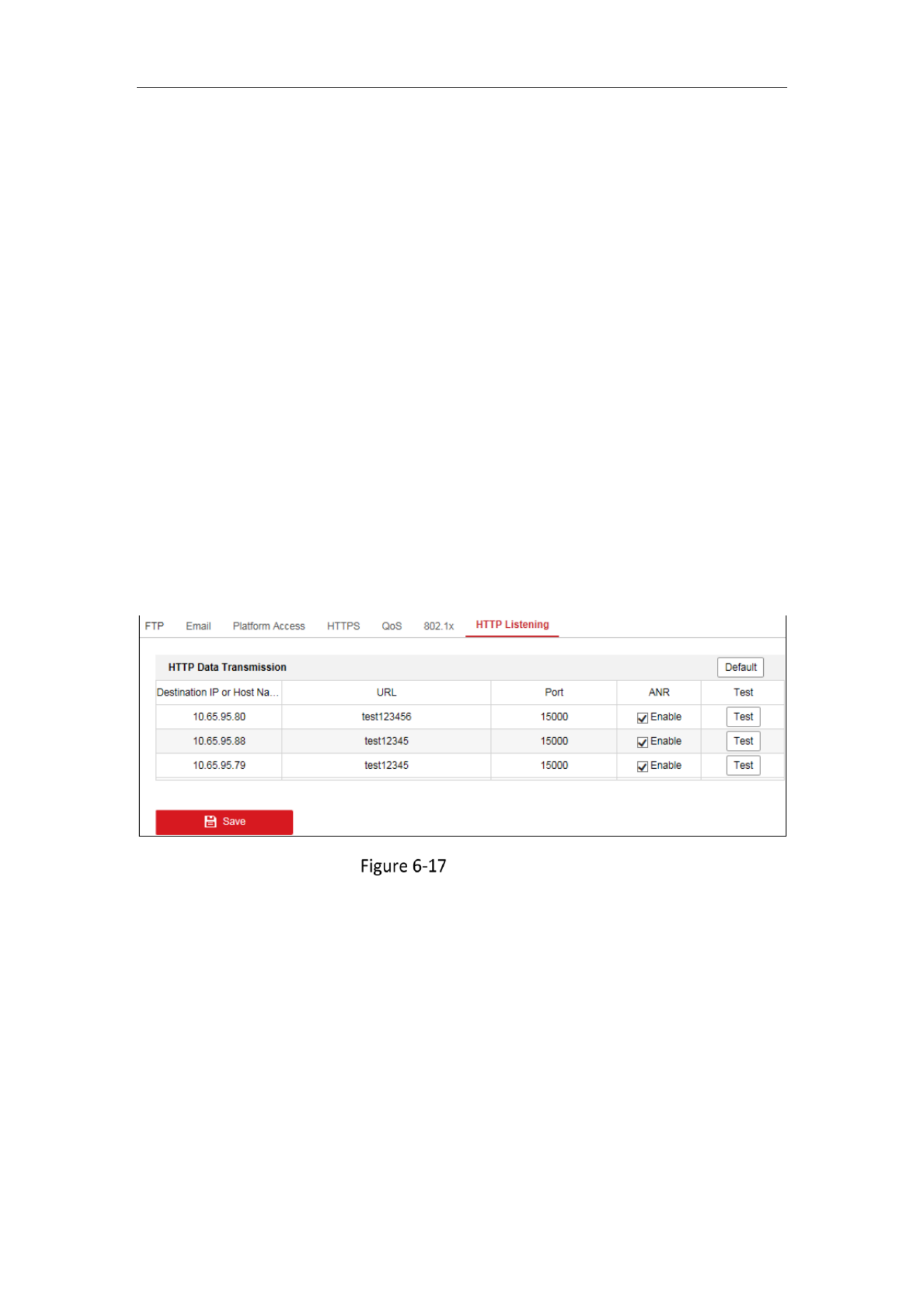
6.2.9 Configuring HTTP Listening
Purpose:
The camera can send alarm information to the destination IP or host name via HTTP
protocol. If the network is disconnected, the data can be uploaded to the destination
IP or host name after the network connection is normal.
Before you start:
The destination IP or host name should support the HTTP protocol to receive the
alarm information.
Steps:
1. Enter the HTTP Listening interface, Configuration > Network > Advanced
Settings > Listening.
HTTP Listening
2. Enter the desired destination IP or host name, URL and port.
3. You can click Test to test whether the entered IP address or host name are valid.
4. Or you can click Default to reset the destination IP or host name.

Network Camera User Manual
75
• For some models, the is not enabled by default. Go to Third Stream System >
Maintenance > System Service> Software to enable the function is required.
• The main stream is usually for recording and live view with good bandwidth,
and the sub stream can be used for live view when the bandwidth is limited.-
4. You can customize the following parameters for the selected stream type.
Video Type:
Select the stream type to video stream, or video & audio composite stream. The
audio signal will be recorded only when the Video Type Video & Audio is .
Resolution:
Select the resolution of the video output.
Bitrate Type:
Select the bitrate type to constant or variable.
Video Quality:
When bitrate type is selected as Variable, 6 levels of video quality are selectable.
Frame Rate:
Set the frame rate. The frame rate is to describe the frequency at which the video
stream is updated and it is measured by frames per second (fps). A higher frame
rate is advantageous when there is movement in the video stream, as it maintains
image quality throughout.
Max. Bitrate:
Set the max. bitrate from to 16384 Kbps. The higher value corresponds to the 32
higher video quality, but the better bandwidth is required.
Note: The maximum limit of the max. bitrate value varies according to different
camera platforms. For certain cameras, the maximum limit is 8192 Kbps or 12288
Kbps.
Video Encoding:
The camera supports multiple video encodings types, such as H.264, H.265,
MJPEG, and MPEG4. Supported encoding type for different stream types may
differ. H.265 is a new encoding technology. Compared with H.264, it reduces the
transmission bitrate under the same resolution, frame rate and image quality.

Network Camera User Manual
76
Note: Selectable video encoding types may vary according to different camera
modes.
H.264+ and H.265+:
• H.264+: If you set the main stream as the stream type, and H.264 as the video
encoding, you can see H.264+ available. H.264+ is an improved compression
coding technology based on H.264. By enabling H.264+, users can estimate
the HDD consumption by its maximum average bitrate. Compared to H.264,
H.264+ reduces storage by up to 50% with the same maximum bitrate in
most scenes.
• H.265+: If you set the main stream as the stream type, and H.265 as the video
encoding, you can see H.265+ available. H.265+ is an improved compression
coding technology based on H.265. By enabling H.265+, users can estimate
the HDD consumption by its maximum average bitrate. Compared to H.265,
H.265+ reduces storage by up to 50% with the same maximum bitrate in
most scenes.
You need to reboot the camera if you want to turn on or turn off the
H.264+/H.265+. If you switch from H.264+ to H.265+ directly, and vice versa, a
reboot is not required by the system.
Notes:
• Upgrade your video player to the latest version if live view or playback does
not work properly due to compatibility.
• With H.264+/H.265+ enabled, the parameters such as profile, I frame interval,
video quality, and SVC are greyed out.
• With H.264+/H.265+ enabled, some functions are not supported. For those
functions, corresponding interfaces will be hidden.
• H.264+/H.265+ can spontaneously adjust the bitrate distribution according
the requirements of the actual scene in order to realize the set maximum
average bitrate in the long term. The camera needs at least 24 hours to adapt
to a fixed monitoring scene.
Max. Average Bitrate:

Network Camera User Manual
77
When you set a maximum bitrate, its corresponding recommended maximum
average bitrate will be shown in the Max. Average Bitrate box. You can also set
the maximum average bitrate manually from 32 Kbps to the value of the set
maximum bitrate.
Prole:
When you select H.264 or H.265 as video encoding, you can set the prole.
Selectable proles vary according to camera models.
I Frame Interval:
Set Frame Interval from 1 to I 400.
SVC:
Scalable Video Coding is an extension of the H.264/AVC and H.265 standard.
Select OFF/ON to disable/enable the SVC funcon. Select Auto and the device will
automacally extract frames from the original video when the network
bandwidth is insucient.
Smoothing:
It refers to the smoothness of the stream. The higher value of the smoothing is,
the beer uency of the stream will be, though, the video quality may not be so
sasfactory. The lower value of the smoothing is, the higher quality of the stream
will be, though it may appear not uent.
5. Click Save to save the sengs.
Note:
The video parameters vary according to dierent camera models. Refer to the actual
display page for camera funcons.
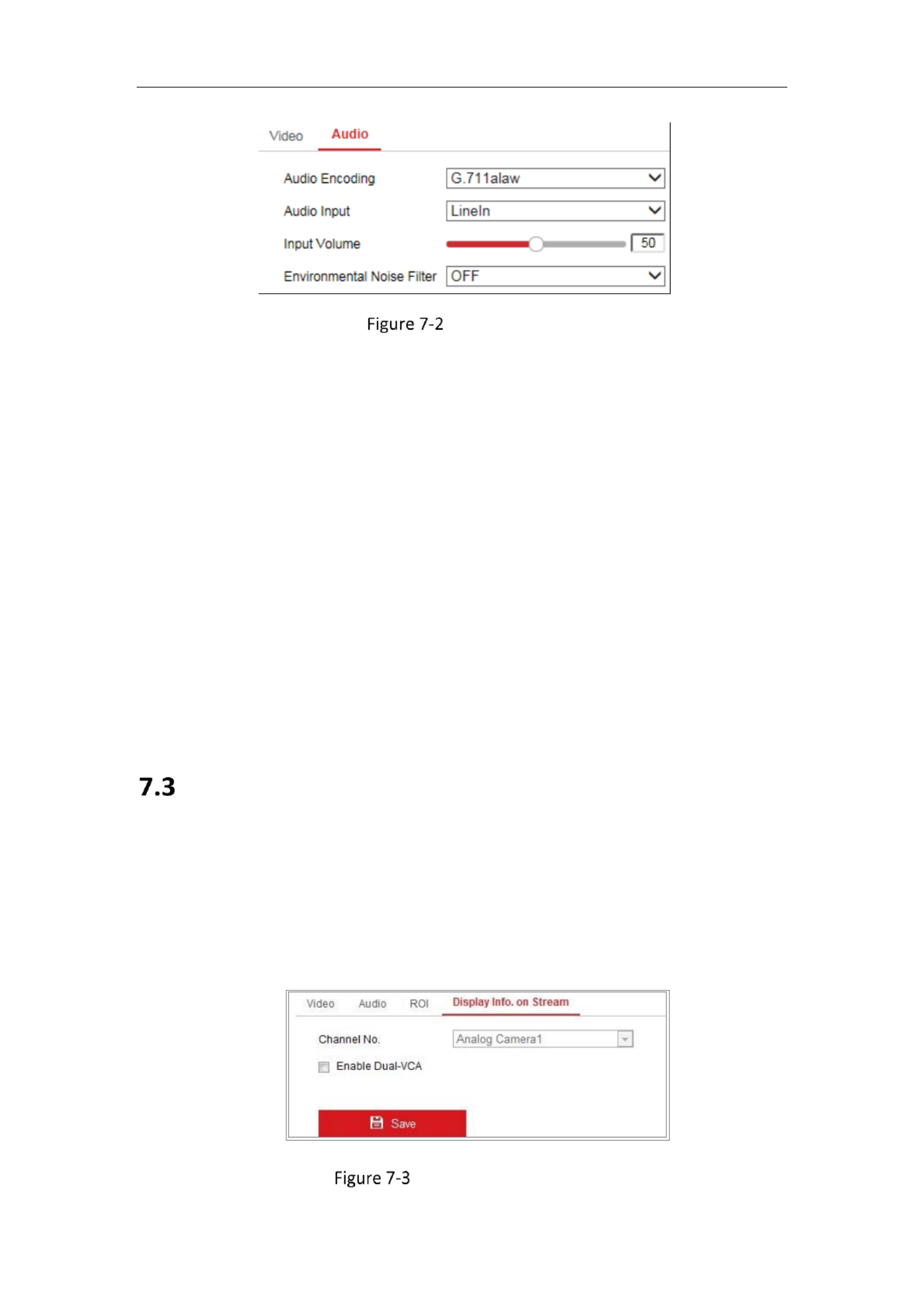
Conguring Audio Setngs
Steps:
1. Enter the Audio Seings interface: Conguraon > Video/Audio > Audio .
Network Camera User Manual
78
Audio Settings
2. Configure the following settings.
Note: Audio settings vary according to different camera models.
Audio Encoding: G.722.1, G.711 ulaw, G.711alaw, G.726, MP2L2 and PCM are
selectable. For MP2L2, the Sampling Rate and Audio Stream Bitrate are
configurable. For PCM, the Sampling Rate can be set.
Audio Input: MicIn and LineIn are selectable for the connected microphone and
pickup respectively.
Input Volume: 0 adjustable.-100
Environmental Noise Filter: Set it as OFF or ON. When the function is enabled,
the noise in the environment can be filtered to some extent.
3. Click Save to save the settings.
Display Info. on Stream
Check the checkbox of , and the information of the objects (e.g. Enable Dual VCA-
human, vehicle, etc.) will be marked in the video stream. Then, you can set rules on
the connected rear end device to detect the events including line crossing, intrusion, -
etc.
Display Info. on Stream

Network Camera User Manual
79
Conguring Target Cropping
Purpose:
You can specify a target area on the live video, and then the specied video area can
be displayed via the third stream in certain resoluon, providing more details of the
target area if needed.
Note: Target cropping funcon varies according to dierent camera models.
Steps:
1. Enter the Target Cropping sengs interface.
2. Check Enable Target Cropping checkbox to enable the funcon.
3. Set Third Stream as the stream type.
4. Select the cropping resoluon for the video display of target area. A red
rectangle is displayed on the live video to mark the target area, and you can
click and drag the rectangle to locate the target area as desired.- -
Click Save to save the setngs.

Network Camera User Manual
80
Chapter 8 Image Setngs
Purpose:
Follow the instrucons in this chapter to congure the image parameters, including
display sengs, OSD setngs, and picture overlay.
Conguring Display Setngs
Purpose:
Congure the image adjustment, exposure sengs, day/night switch, backlight
sengs, white balance, image enhancement, and video adjustment in display
sengs.
Note: The display parameters vary according to the dierent camera models. Please
refer to the actual interfa for details.ce
Steps:
1. Enter the Display Setngs interface, Conguraon > Image > Display Sengs.
Display Sengs
2. Set the image parameters of the camera.
Note: In order to guarantee the image quality in dierent illuminaon, it provides
two sets of parameters for users to congure.
Image Adjustment
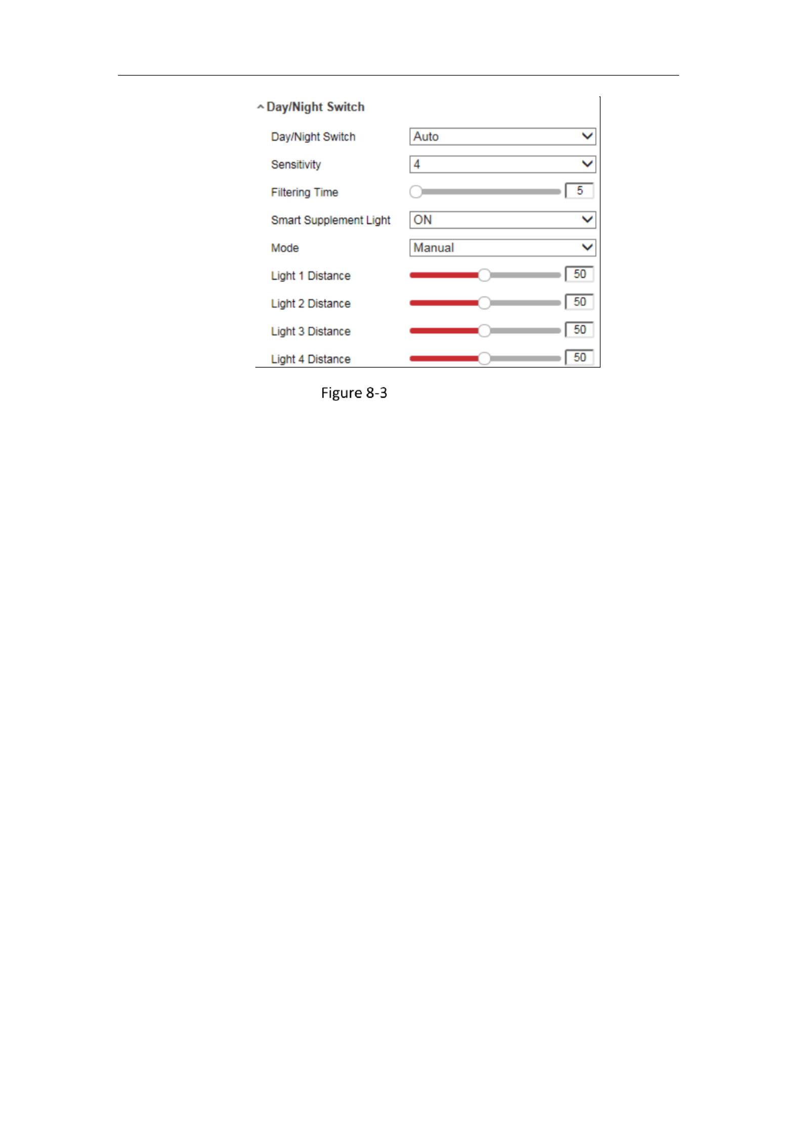
Network Camera User Manual
82
Day/Night Switch
Day: the camera stays at day mode.
Night: the camera stays at night mode.
Auto: the camera switches between the day mode and the night mode according
to the illumination automatically. The sensitivity ranges from 0 to 7, the higher
the value is, the easier the mode switches. The refers to the Filtering Time
interval time between the day/night switch. You can set it from 5s to 120s.
Scheduled Switch:- Set the start time and the end time to define the duration for
day/night mode.
Triggered by alarm input: The switch is triggered by alarm input. You can set the
triggered mode to day or night.
Smart Supplement Light: Set the supplement light to ON, and Auto and Manual
are selectable for light mode.
Select , and the supplement light changes according to the actual Auto
luminance. E.g., if the current scene is bright enough, then the supplement light
adjusts itself to lower power; and if the scene is not bright enough, the light
adjusts itself to higher power.
Select and you can adjust the distance of the supplement light. There Manual,
are four supplement lights and you can adjust the distance for the each light. If
the object is near the camera, the device adjusts the supplement light to lower
power, and the light is in higher power if the object is far away.

Network Camera User Manual
84
Grey Scale: You can choose the range of the grey scale as [0 255] or [16 235].- -
Video Adjustment
Mirror : It mirrors the image so you can see it inversed. Left/Right, Up/Down,
Center, and OFF are selectable.
Rotate : To make a complete use of the 16:9 aspect ratio, you can enable the
rotate function when you use the camera in a narrow view scene.
When installing, turn the camera to the 90 degrees or rotate the 3 axis lens to 90 -
degrees, and set the rotate mode as on, you will get a normal view of the scene
with 9:16 aspect ratio to ignore the needless information such as the wall, and
get more meaningful information of the scene.
Scene Mode: Choose the scene as indoor or outdoor according to the real
environment.
Video Standard: 50 Hz and 60 Hz are selectable. Choose according to the
different video standards; normally 50 Hz for PAL standard and 60 Hz for NTSC
standard.
Lens Distortion Correction: For cameras equipped with motor driven lens, image -
may appear distorted to some extent. Turn on this function to correct the
distortion.
Others
Some camera models support CVBS, SDI, or HDMI output. Set the local output
ON or OFF according to the actual device.
Configuring OSD Settings
Purpose:
You can customize the camera name, time/date format, display mode, and OSD size
displayed on the live view.

Network Camera User Manual
85
OSD Settings
Steps:
1. Enter the OSD Settings interface: Configuration > Image > OSD Settings.
2. Select the desired channel number from the drop down list.-
3. Check the corresponding checkbox to select the display of camera name, date or
week if required.
4. Edit the camera name in the text field of Camera Name.
5. Select from the drop down list to set the time format and date format.-
6. Select from the drop down list to set the time format, date format, display mode, -
OSD size and OSD color.
7. Configure the text overlay settings.
(1) Check the checkbox in front of the textbox to enable the on screen display.-
(2) Input the characters in the textbox.
Note: Up to 8 text overlays are configurable.
8. Adjust the position and alignment of text frames.
Left align, right align and custom are selectable. If you select custom, you can use
the mouse to click and drag text frames in the live view window to adjust their
positions.
Note: The alignment adjustment is only applicable to Text Overlay items.

Network Camera User Manual
86
9. Click Save to save the settings.
Configuring Picture Overlay
Purpose:
Picture overlay enables you to overlay a picture on the image. This function enables a
certain enterprise or users to overlay their logo on the image.
Steps:
1. Enter the Picture Overlay Settings interface, Configuration Image Picture > >
Overlay.
Picture Overlay
2. Select the desired channel number from the drop down list.-
3. Click to select a picture.Browse
4. Click to upload it.Upload
5. Check Enable Picture Overlay checkbox to enable the function.
6. Set X Coordinate and Y Coordinate values adjust the picture position on the
image. Adjust Picture Width and Picture Height to the desired size.
7. Click to save settings.Save
Note: The picture must be in RGB24 bmp format and the maximum picture size is
128*128.

Network Camera User Manual
87
Chapter 9 Event Settings
This section explains how to configure the network camera to respond to alarm
events, including basic event and smart event.
Basic Events
You can configure the basic events by following the instructions in this section,
including alarm input, alarm output, and exception. These events can trigger the
linkage methods, such as Notify Surveillance Center, Send Email, Trigger Alarm
Output, etc.
Note: Check the checkbox of Notify Surveillance Center if you want the alarm
information to be pushed to PC or mobile client software as soon as the alarm is
triggered.
9.1.1 Configuring Alarm Input
Steps:
1. Enter the Alarm Input Settings interface: Configuration > Event Basic Event > >
Alarm Input.
2. Choose the alarm input No. and the Alarm Type. The alarm type can be NO
(Normally Open) and NC (Normally Closed). Edit the name to set a name for the
alarm input (optional).
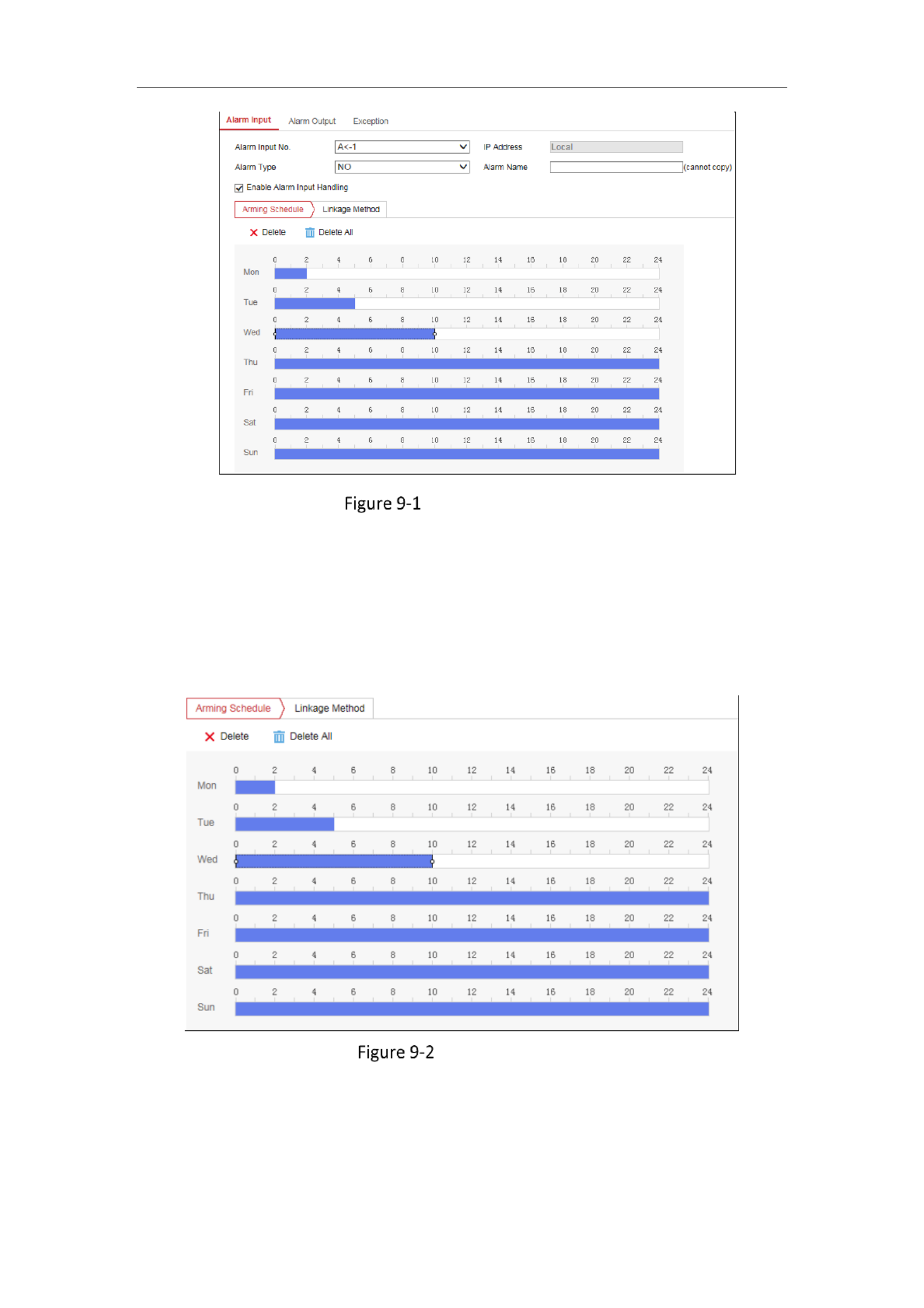
Network Camera User Manual
88
Alarm Input Settings
3. Click to set the arming schedule for the alarm input.Arming Schedule
Task 1: Set the Arming Schedule
Steps:
1) Click Arming Schedule to edit the arming schedule.
2) Click on the time bar and drag the mouse to select the time period.
Arming Schedule
Note: Click on the selected time period, you can adjust the time period to the
desired time by either moving the time bar or input the exact time period.
3) (Optional) Click Delete to delete the current arming schedule, or click Save to

Network Camera User Manual
89
save the settings.
4) Move the mouse to the end of each day, a copy dialogue box pops up, and you
can copy the current settings to other days.
5) Click Save to save the settings.
Note: The time of each period can’t be overlapped. Up to 8 periods can be
configured for each day.
4. Click Linkage Method and check the checkbox to select the linkage method for
the alarm input.
Task 2: Set the Linkage Method
Check the checkbox to select the linkage method. Audible Warning, Send Email,
Notify Surveillance Center, Upload to FTP/Memory Card/NAS, Trigger Channel and
Trigger Alarm Output are selectable. You can specify the linkage method when an
event occurs.
Linkage Method
Note: The linkage methods vary according to the different camera models.
Audible Warning
Trigger the audible warning locally. And it only supported by the device that
have the audio output.
Notify Surveillance Center
Send an exception or alarm signal to remote management software when an

Network Camera User Manual
90
event occurs.
Send Email
Send an email with alarm information to a user or users when an event occurs.
Note: To send the Email when , please refer to to an event occurs Section 7.2.3
complete Email setup in advance.
Upload to FTP/Memory Card/NAS
Capture the image when an alarm is triggered and upload the picture to a FTP
server.
Notes:
● Set the FTP address and the remote FTP server first. Refer to Section 6.2.2
Configuring FTP Settings for detailed information.
● Go to Configuration > Storage > Schedule Settings> Capture > Capture
Parameters page, enable the event triggered snapshot, and set the capture -
interval and capture number.
● The captured image can also be uploaded to the available SD card or
network disk.
Trigger Channel
The video will be recorded when the motion is detected. You have to set the
recording schedule to realize this function. Please refer to for Section 11.1
detailed information.
Trigger Alarm Output
Trigger one or more external alarm outputs when an event occurs.
Note: To trigger an alarm output when an event occurs, please refer to
Configuring Alarm Output to set the related parameters.
5. You can copy your settings to other alarm inputs.
6. Click Save to save the settings.
9.1.2 Configuring Alarm Output
Steps:

Network Camera User Manual
91
1. Enter the Alarm Output Settings interface: Configuration> Event Basic Event > >
Alarm Output.
Alarm Output Settings
2. Select one alarm output channel in the drop down list. You can Alarm Output -
also set a name for the alarm output (optional).
3. The Delay time can be set to 5sec, 10sec, 30sec, 1min, 2min, 5min, 10min or
Manual The delay time refers to the time duration that the alarm output .
remains in effect after alarm occurs.
4. Click to enter the Edit Schedule Time interface. The time Arming Schedule
schedule configuration is the same as the settings of the arming schedule for
motion detection Refer to Task 1 Set the Arming Schedule: in Section 9.1.1.
5. You can copy the settings to other alarm outputs.
6. Click Save to save the settings.
9.1.3 Handling Exception
The exception type can be HDD full, HDD error, network disconnected, IP address
conflicted and illegal login to the cameras.
Steps:
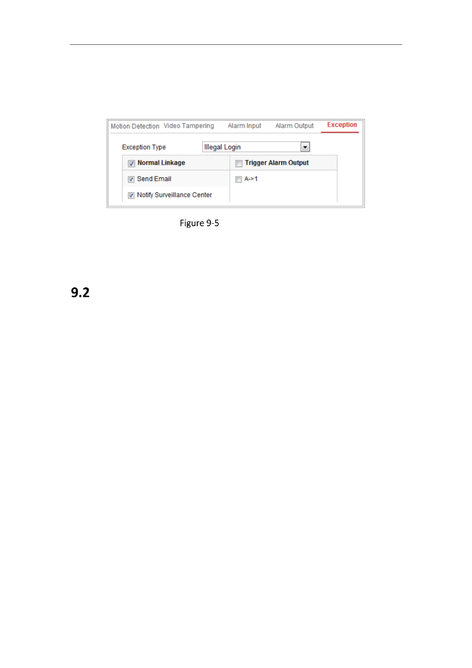
Network Camera User Manual
92
1. Enter the Excepon Sengs interface: Configuration > Event Basic Event > >
Exception .
2. Check the checkbox to set the acons taken for the Excepon alarm.
Excepon Setngs
3. Click Save to save the setngs.
Smart Events
You can congure the smart events by following the instrucons in this secon,
including audio excepon detecon, defocus detecon, scene change detecon,
intrusion detecon, and line crossing detecon, etc. These events can trigger the
linkage methods, such as Nofy Surveillance Center, Send Email, Trigger Alarm
Output, etc.
9.2.1 Configuring Audio Exception Detection
Purpose:
Audio excepon detecon funcon detects the abnormal sounds in the surveillance
scene, such as the sudden increase/decrease of the sound intensity, and some
certain acons can be taken when the alarm is triggered.
Note: Audio excepon detecon funcon varies according to dierent camera
models.
Steps:
1. Enter the Audio Excepon Detecon sengs interface, Configuration > Event >

Network Camera User Manual
93
Smart Event > Audio Excepon Detecon.
Audio Excepon Detecon
2. Check the checkbox of to enable the audio loss detecon Audio Loss Excepon
funcon.
3. Check the checkbox of to detect Sudden Increase of Sound Intensity Detecon
the sound steep rise in the surveillance scene. You can set the detecon
sensivity and threshold for sound steep rise.
4. Check the checkbox of to detect Sudden Decrease of Sound Intensity Detecon
the sound steep drop in the surveillance scene. You can set the detecon
sensivity and threshold for sound steep drop.
Notes:
Sensivity: Range [1-100], the smaller the value is, the more severe the
change should be to trigger the detecon.
Sound Intensity Threshold: Range [1-100], it can lter the sound in the
environment, the louder the environment sound, the higher the value
should be. You can adjust it according to the real environment.
You can view the real-me volume of the sound on the interface.
5. Click to set the arming schedule. Arming Schedule
6. Click and select the linkage methods for audio excepon, Linkage Method
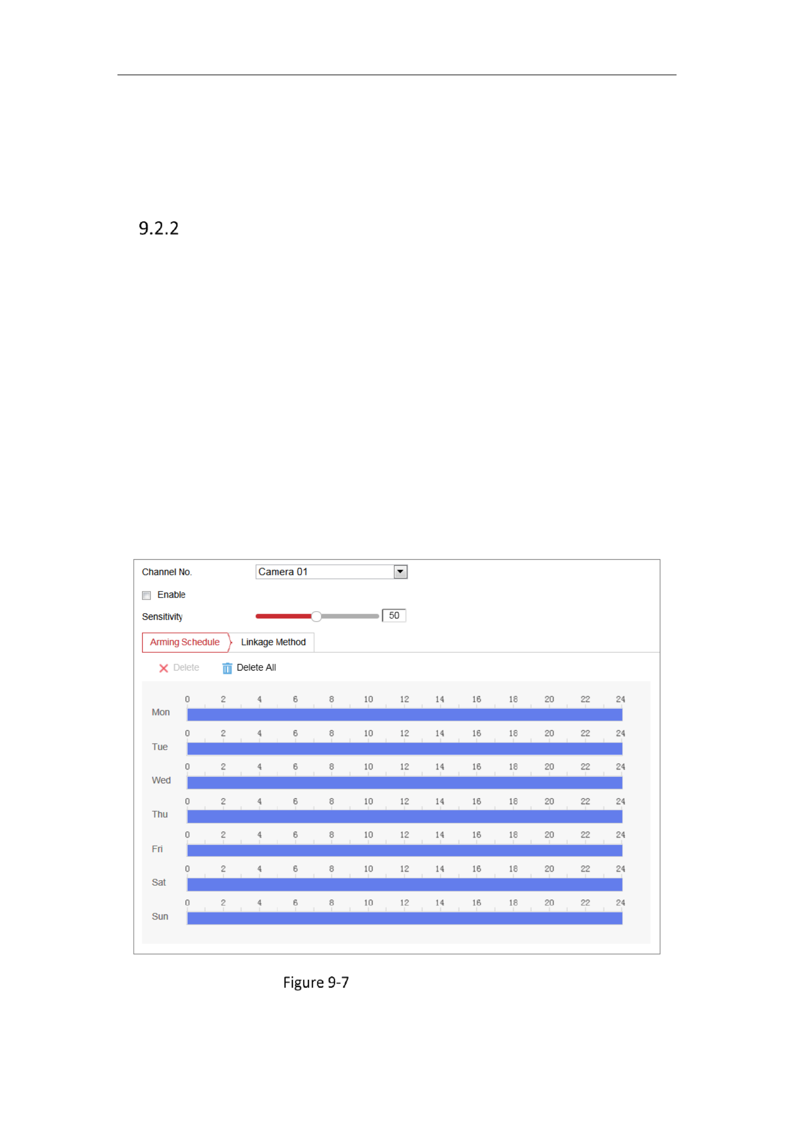
Network Camera User Manual
94
including Nofy Surveillance Center, Send Email, Upload to FTP/Memory
Card/NAS, Trigger Channel for recording and Trigger Alarm Output.
7. Click to save the sengs. Save
Conguring Scene Change Detecon
Purpose:
Scene change detecon funcon detects the change of surveillance environment
aected by the external factors, such as the intenonal rotaon of the camera.
Some certain acons can be taken when the alarm is triggered.
Note: Scene change detecon funcon varies according to dierent camera models.
Steps:
1. Enter the Scene Change Detecon sengs interface, Conguraon > Event >
Smart Event > Scene Change Detecon.
2. Select the Camera No.
Scene Change Detecon
3. Check the checkbox of to enable the funcon. Enable

Network Camera User Manual
95
4. Click-and-drag the slider to set the detecon sensivity. The sensivity value
ranges from 1 to 100, and the higher the value is, the more easily the change of
scene can trigger the alarm.
5. Click to set the arming schedule. Arming Schedule
6. Click to select the linkage methods for scene change, including Linkage Method
Nofy Surveillance Center, Send Email, Upload to FTP/Memory Card/NAS,
Trigger Channel and Trigger Alarm Output.
7. Click to save the sengs. Save
Conguring Intrusion Detecon
Purpose:
Intrusion detecon funcon detects people, vehicle or other objects which enter and
loiter in a pre-dened virtual region, and some certain acons can be taken when
the alarm is triggered.
Note: Intrusion detecon funcon varies according to dierent camera models.
Steps:
1. Enter the Intrusion Detecon sengs interface, Conguraon> Event > Smart
Event > Intrusion Detecon.
2. Select the Camera No.
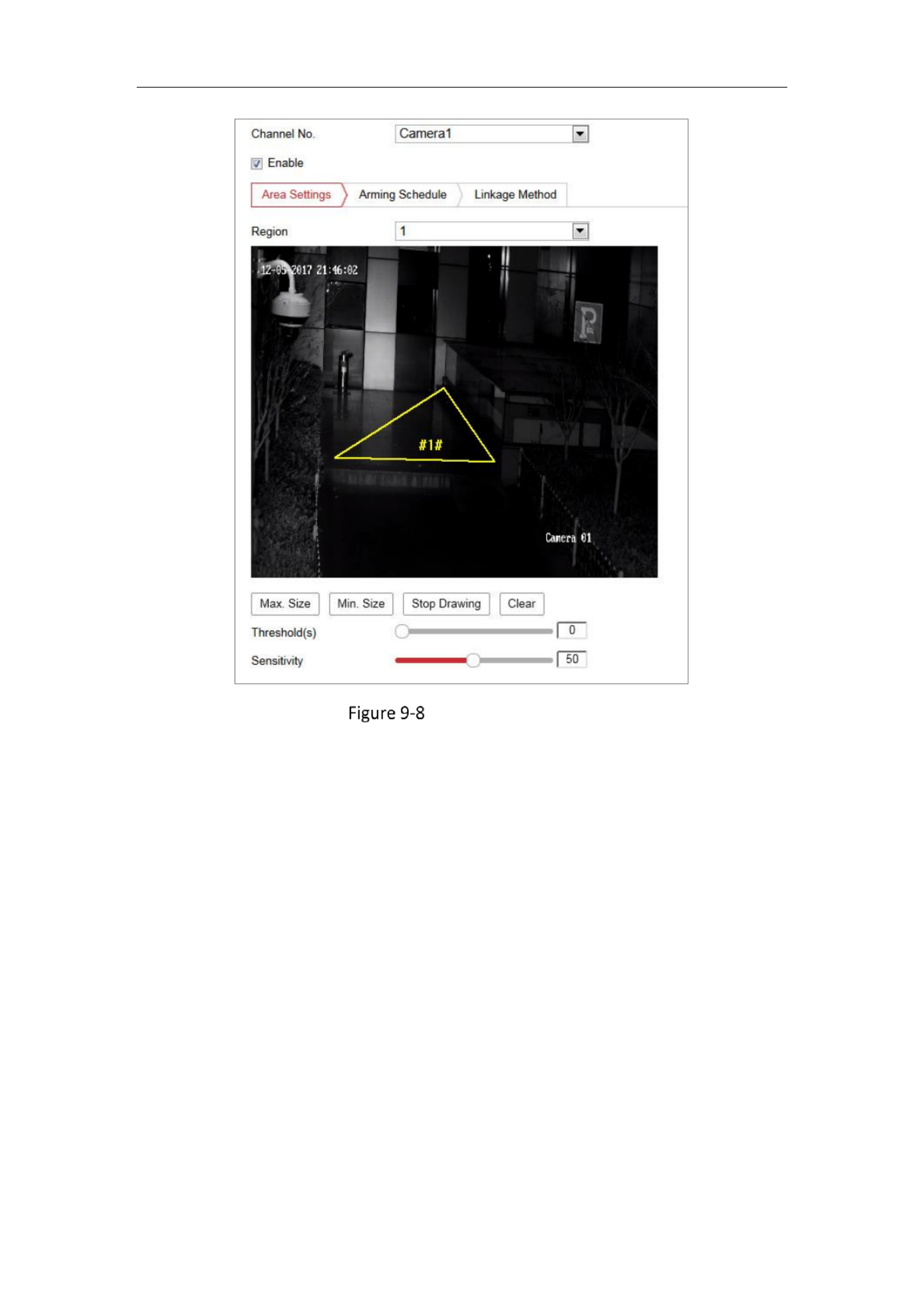
Network Camera User Manual
96
Intrusion Detecon
3. Check the checkbox of to enable the funcon. Enable
4. Select a region number from the drop-down list of . Region
Region: A pre-dened vertexes area on the live view image. Targets, such as,
people, vehicle or other objects, who enter and loiter in the region will be
detected and trigger the set alarm.
5. Click tab and click buon to start the region drawing. Area Sengs Draw Area
6. Click on the live video to specify the four vertexes of the detecon region, and
right click to complete drawing.
7. Set the Max. Size and Min. Size for valid targets. Targets smaller or larger than
the valid target size are not able to trigger detecon.
Max. Size: The maximum size of a valid target. Targets with larger sizes would
not trigger detecon.

Network Camera User Manual
97
Min. Size: The minimum size of a valid target. Targets with smaller sizes would
not trigger detecon.
8. Click when nish drawing. Stop Drawing
9. Set the me threshold for intrusion detecon.
Threshold: Range [0s-10s], the threshold for the me of the object loitering in
the region. If you set the value as 0, alarm is triggered immediately aer the
object entering the region.
10. Drag the slider to set the sensivity value.
Sensivity: Range [1-100]. Sensivity stands for the percentage of the body part
of an acceptable target that enters the pre-dened region.
Sensivity = 100 S–1/ST*100
S1 stands for the target body part that goes across the pre-dened region. S T
stands for the complete target body.
Example: if you set the value as 60, the acon can be counted as an intrusion
only when 40 percent body part enters the region.
Note: The of the detecon is supported by certain models. Refer to Sensitivity
actual display for details.
11. Repeat the above steps to congure other regions. Up to 4 regions can be set.
You can click the buon to clear all pre-dened regions. Clear
12. Click to set the arming schedule. Arming Schedule
13. Click Linkage Method to select the linkage methods for intrusion detecon,
including Nofy Surveillance Center, Send Email, Upload to FTP/Memory
Card/NAS, Trigger Channel and Trigger Alarm Outpu t.
14. Click to save the sengs. Save
Configuring Line Crossing Detection
Purpose:

Network Camera User Manual
98
Line crossing detecon funcon detects people, vehicle or other objects which cross
a pre-dened virtual line, and some certain acons can be taken when the alarm is
triggered.
Note: Line crossing detecon funcon varies according to different camera models.
Steps:
1. Enter the Line Crossing Detecon sengs interface, Configuration > Event >
Smart Event > Line Crossing Detection.
2. Select the Camera No.
Line Crossing Detecon
3. Check the checkbox of to enable the funcon. Enable
4. Select the line from the drop-down list.
5. Click tab and click buon, and a virtual line is displayed Area Settings Draw Area

Network Camera User Manual
99
on the live video.
6. Drag the line, and you can locate it on the live video as desired. Click on the line,
two red squares are displayed on each end, and you can click-and-drag one of
the red squares to define the shape and length of the line.
7. Set the Max. Size and Min. Size for valid targets. Targets smaller or larger than
the valid target size are not able to trigger detection.
Max. Size: The maximum size of a valid target. Targets with larger sizes would
not trigger detection.
Min. Size: The minimum size of a valid target. Targets with smaller sizes would
not trigger detection.
8. Select the direction for line crossing detection. And you can select the directions
as A< >B, A >B, and B >A.- - -
A<->B: The object going across the plane with both directions can be detected
and alarms are triggered.
A->B: Only the object crossing the configured line from the A side to the B side
can be detected.
B->A: Only the object crossing the configured line from the B side to the A side
can be detected.
9. Click when finish drawing. Stop Drawing
10. Drag the slider to set the sensitivity value.
Sensitivity: Range [1-100]. It stands for the percentage of the body part of an
acceptable target that goes across the pre-defined line.
Sensitivity = 100 S– 1/ST
*100
S1 stands for the target body part that goes across the pre-defined line. S T
stands
for the complete target body.
Example: if you set the value as 60, the action can be counted as a line crossing
action only when 40 percent or more body part goes across the line.
Note: The of the detection is supported by certain models. Refer to Sensitivity
actual display for details.
11. Repeat the above steps to configure other lines. Up to 4 lines can be set. You can

Network Camera User Manual
100
click the button to clear all pre-defined lines. Clear
12. Click the to set the arming schedule. Arming Schedule
13. Select the linkage methods for line crossing detection, including Notify
Surveillance Center, Send Email, Upload to FTP/Memory Card/NAS, Trigger
Channel and Trigger Alarm Output.
14. Click to save the settings. Save
Configuring Region Entrance Detection
Purpose:
Region entrance detection function detects people, vehicle or other objects which
enter a pre defined virtual region from the outside place, and some certain actions -
can be taken when the alarm is triggered.
Steps:
1. Enter the Region Entrance Detection settings interface, Configuration > Event >
Smart Event > Region Entrance Detection.
2. Select the Camera No.

Network Camera User Manual
101
Region Entrance Detection
3. Check the checkbox to enable the function.Enable
4. Select the from the drop down list for detection settings.Region -
5. Click Area Settings Draw Area and click button to start the area drawing.
6. Click on the live video to specify the four vertexes of the detection region, and
right click to complete drawing.
7. Set the Max. Size and Min. Size for valid targets. Targets smaller or larger than
the valid target size are not able to trigger detection.
Max. Size: The maximum size of a valid target. Targets with larger sizes would
not trigger detection.
Min. Size: The minimum size of a valid target. Targets with smaller sizes would
not trigger detection.
8. Click when finish drawing. Stop Drawing
9. Drag the slider to set the sensitivity value.
Product specificaties
| Merk: | Hikvision |
| Categorie: | Bewakingscamera |
| Model: | DS-2CD6944G0-IHS(/NFC) |
| Soort: | IP-beveiligingscamera |
| Gebruikershandleiding: | Ja |
| Materiaal behuizing: | Aluminium |
| Internationale veiligheidscode (IP): | IP67 |
| Maximale capaciteit van de geheugenkaart: | 256 GB |
| Stemcodecs: | G.711, G.722.1, G.726, MP2L2, PCM |
| Automatisch scherpstellen: | Ja |
| Ondersteuning voor plaatsing: | Buiten |
| Connectiviteitstechnologie: | Bedraad |
| Ethernet LAN: | Ja |
| Maximum resolutie: | 4800 x 2688 Pixels |
| Videocompressieformaten: | H.264, H.265 |
| Stroomuitvoer (volt): | 12 |
| Minimale belichting: | 0 Lux |
| Geïntegreerde geheugenkaartlezer: | Ja |
| Compatibele geheugenkaarten: | MicroSD (TransFlash), SDHC, SDXC |
| Infrarood wavelength: | 850 nm |
| HTTPS-encryptie: | Ja |
| Aantal Ethernet LAN (RJ-45)-poorten: | 1 |
| Focus: | Gemotoriseerde/handmatig |
| Omvang optische sensor: | 1/1.8 " |
| Type beeldsensor: | CMOS |
| Camera sluitertijd: | 1/100 s |
| Webbrowser: | Ja |
| Aantal gebruikers: | 32 gebruiker(s) |
| Ondersteunde netwerkprotocollen: | TCP/IP, ICMP, HTTP, HTTPS, FTP, DHCP, DNS, DDNS, RTP, RTSP, RTCP, PPPoE, NTP, UPnP, SMTP, SNMP, IGMP, 802.1X, QoS, IPv6, UDP, Bonjour |
| Audio-uitgangskanalen: | 1 kanalen |
| IP-adresfilter: | Ja |
| Progressive scan: | Ja |
| Ethernet interface type: | Fast Ethernet |
| IK code: | IK10 |
| Sample rate: | 48 kHz |
| Pan bereik: | 0 - 355 ° |
| Videostreaming: | Ja |
| Bewegingssensor: | Ja |
| Infrarood (IR)-afsluitingsfilter: | Ja |
| Achtergrondverlichting compensatie: | Ja |
| Alarm ingang/uitgang: | Ja |
| Aantal talen: | 1 |
| Highlight Compensation (HLC) (compensatie voor sterke belichting): | Ja |
| Bitrate: | 32 Kbps - 16 Mbps |
| Bedrijfstemperatuur (T-T): | -40 - 60 °C |
| Bereik kantelhoek: | 0 - 90 ° |
| Audio invoer kanalen: | 1 |
| Anti-flikkering: | Ja |
| Hartslag: | Ja |
Heb je hulp nodig?
Als je hulp nodig hebt met Hikvision DS-2CD6944G0-IHS(/NFC) stel dan hieronder een vraag en andere gebruikers zullen je antwoorden
Handleiding Bewakingscamera Hikvision

7 Februari 2025
7 Februari 2025
7 Februari 2025
7 Februari 2025
7 Februari 2025
7 Februari 2025
5 Februari 2025
5 Februari 2025
6 Januari 2025
18 December 2024
Handleiding Bewakingscamera
- Bewakingscamera Braun
- Bewakingscamera Bosch
- Bewakingscamera Philips
- Bewakingscamera Sony
- Bewakingscamera Samsung
- Bewakingscamera Xiaomi
- Bewakingscamera Panasonic
- Bewakingscamera Asus
- Bewakingscamera Canon
- Bewakingscamera Garmin
- Bewakingscamera Grundig
- Bewakingscamera Gigaset
- Bewakingscamera Honeywell
- Bewakingscamera JVC
- Bewakingscamera Motorola
- Bewakingscamera Pioneer
- Bewakingscamera Toshiba
- Bewakingscamera VTech
- Bewakingscamera Abus
- Bewakingscamera ACME
- Bewakingscamera Acti
- Bewakingscamera Ag Neovo
- Bewakingscamera Airlive
- Bewakingscamera Aldi
- Bewakingscamera Alecto
- Bewakingscamera Allnet
- Bewakingscamera Aluratek
- Bewakingscamera Anker
- Bewakingscamera Apc
- Bewakingscamera Aqara
- Bewakingscamera Aritech
- Bewakingscamera Avanti
- Bewakingscamera AVTech
- Bewakingscamera Axis
- Bewakingscamera Beafon
- Bewakingscamera Belkin
- Bewakingscamera Blaupunkt
- Bewakingscamera Boss
- Bewakingscamera Brinno
- Bewakingscamera BRK
- Bewakingscamera Buffalo
- Bewakingscamera Burg-Wachter
- Bewakingscamera D-Link
- Bewakingscamera Dedicated Micros
- Bewakingscamera Denver
- Bewakingscamera Digitus
- Bewakingscamera DIO
- Bewakingscamera Dorr
- Bewakingscamera E-bench
- Bewakingscamera Ebode
- Bewakingscamera Edimax
- Bewakingscamera Ednet
- Bewakingscamera Elmo
- Bewakingscamera Elro
- Bewakingscamera Eminent
- Bewakingscamera Engenius
- Bewakingscamera Eufy
- Bewakingscamera EverFocus
- Bewakingscamera Extech
- Bewakingscamera Ezviz
- Bewakingscamera Ferguson
- Bewakingscamera First Alert
- Bewakingscamera Flamingo
- Bewakingscamera Flir
- Bewakingscamera Foscam
- Bewakingscamera Friedland
- Bewakingscamera Ganz
- Bewakingscamera Gembird
- Bewakingscamera Genius
- Bewakingscamera GeoVision
- Bewakingscamera Gira
- Bewakingscamera Google
- Bewakingscamera Grandstream
- Bewakingscamera Hama
- Bewakingscamera Iget
- Bewakingscamera Iiquu
- Bewakingscamera Iluv
- Bewakingscamera Indexa
- Bewakingscamera InFocus
- Bewakingscamera Interlogix
- Bewakingscamera Ion
- Bewakingscamera Kerbl
- Bewakingscamera KlikaanKlikuit
- Bewakingscamera Kodak
- Bewakingscamera Kogan
- Bewakingscamera Konig
- Bewakingscamera Laserliner
- Bewakingscamera LevelOne
- Bewakingscamera Linksys
- Bewakingscamera Logilink
- Bewakingscamera Logitech
- Bewakingscamera Lorex
- Bewakingscamera Maginon
- Bewakingscamera Manhattan
- Bewakingscamera Marmitek
- Bewakingscamera Marquant
- Bewakingscamera Marshall
- Bewakingscamera Megasat
- Bewakingscamera Minox
- Bewakingscamera Mitsubishi
- Bewakingscamera Monacor
- Bewakingscamera Nedis
- Bewakingscamera Nest
- Bewakingscamera Netatmo
- Bewakingscamera Netgear
- Bewakingscamera Netis
- Bewakingscamera Notifier
- Bewakingscamera Perel
- Bewakingscamera Powerfix
- Bewakingscamera Profile
- Bewakingscamera Provision ISR
- Bewakingscamera Pyle
- Bewakingscamera Quantum
- Bewakingscamera Raymarine
- Bewakingscamera Renkforce
- Bewakingscamera Revo
- Bewakingscamera Ricoh
- Bewakingscamera Ring
- Bewakingscamera Rollei
- Bewakingscamera Sanyo
- Bewakingscamera Satel
- Bewakingscamera Schneider
- Bewakingscamera SecurityMan
- Bewakingscamera Siedle
- Bewakingscamera Sitecom
- Bewakingscamera Smartwares
- Bewakingscamera SMC
- Bewakingscamera Somfy
- Bewakingscamera Sonic Alert
- Bewakingscamera Stabo
- Bewakingscamera Strong
- Bewakingscamera Switel
- Bewakingscamera Synology
- Bewakingscamera Technaxx
- Bewakingscamera Tenda
- Bewakingscamera Thomson
- Bewakingscamera TP Link
- Bewakingscamera Trebs
- Bewakingscamera Trendnet
- Bewakingscamera Trust
- Bewakingscamera Uniden
- Bewakingscamera V-Tac
- Bewakingscamera Velleman
- Bewakingscamera Vitek
- Bewakingscamera Vivotek
- Bewakingscamera Waeco
- Bewakingscamera Western Digital
- Bewakingscamera Withings
- Bewakingscamera Woonveilig
- Bewakingscamera Xavax
- Bewakingscamera Y-cam
- Bewakingscamera Yale
- Bewakingscamera Zebra
- Bewakingscamera ZTE
- Bewakingscamera ZyXEL
- Bewakingscamera Jung
- Bewakingscamera Olympia
- Bewakingscamera Oplink
- Bewakingscamera Orion
- Bewakingscamera Overmax
- Bewakingscamera Clas Ohlson
- Bewakingscamera Caliber
- Bewakingscamera Exibel
- Bewakingscamera Monoprice
- Bewakingscamera Naxa
- Bewakingscamera Niceboy
- Bewakingscamera Schwaiger
- Bewakingscamera Steren
- Bewakingscamera Ubiquiti Networks
- Bewakingscamera EMOS
- Bewakingscamera Conceptronic
- Bewakingscamera Miniland
- Bewakingscamera Arlo
- Bewakingscamera Atlona
- Bewakingscamera Avidsen
- Bewakingscamera Hamlet
- Bewakingscamera Hive
- Bewakingscamera Imou
- Bewakingscamera INSTAR
- Bewakingscamera SereneLife
- Bewakingscamera Defender
- Bewakingscamera Trevi
- Bewakingscamera Adesso
- Bewakingscamera Broan
- Bewakingscamera DSC
- Bewakingscamera M-e
- Bewakingscamera Blow
- Bewakingscamera Genie
- Bewakingscamera ClearOne
- Bewakingscamera Chacon
- Bewakingscamera Swann
- Bewakingscamera Approx
- Bewakingscamera SPC
- Bewakingscamera Canyon
- Bewakingscamera Cisco
- Bewakingscamera EVOLVEO
- Bewakingscamera Whistler
- Bewakingscamera Delta Dore
- Bewakingscamera Furrion
- Bewakingscamera Comtrend
- Bewakingscamera Planet
- Bewakingscamera Blink
- Bewakingscamera Intellinet
- Bewakingscamera Aida
- Bewakingscamera Lindy
- Bewakingscamera AVerMedia
- Bewakingscamera Lumens
- Bewakingscamera Mobi
- Bewakingscamera Fortinet
- Bewakingscamera DataVideo
- Bewakingscamera Hombli
- Bewakingscamera Vaddio
- Bewakingscamera Adj
- Bewakingscamera Ikan
- Bewakingscamera Dahua Technology
- Bewakingscamera UniView
- Bewakingscamera Reolink
- Bewakingscamera Valueline
- Bewakingscamera EVE
- Bewakingscamera QSC
- Bewakingscamera Marshall Electronics
- Bewakingscamera Boyo
- Bewakingscamera IC Intracom
- Bewakingscamera CRUX
- Bewakingscamera POSline
- Bewakingscamera August
- Bewakingscamera Hawking Technologies
- Bewakingscamera Lanberg
- Bewakingscamera Nexxt
- Bewakingscamera Watec
- Bewakingscamera Equip
- Bewakingscamera Crestron
- Bewakingscamera Chuango
- Bewakingscamera ORNO
- Bewakingscamera ETiger
- Bewakingscamera Videcon
- Bewakingscamera Advantech
- Bewakingscamera Moxa
- Bewakingscamera Digital Watchdog
- Bewakingscamera Brilliant
- Bewakingscamera Moen
- Bewakingscamera Kramer
- Bewakingscamera MEE Audio
- Bewakingscamera Brickcom
- Bewakingscamera Kwikset
- Bewakingscamera Linear PRO Access
- Bewakingscamera BirdDog
- Bewakingscamera AVer
- Bewakingscamera Summer Infant
- Bewakingscamera Topica
- Bewakingscamera Vimar
- Bewakingscamera Speco Technologies
- Bewakingscamera Verint
- Bewakingscamera ZKTeco
- Bewakingscamera Rostra
- Bewakingscamera Kguard
- Bewakingscamera Caddx
- Bewakingscamera Spyclops
- Bewakingscamera EKO
- Bewakingscamera Inovonics
- Bewakingscamera Surveon
- Bewakingscamera Hollyland
- Bewakingscamera Epcom
- Bewakingscamera AViPAS
- Bewakingscamera Lutec
- Bewakingscamera Hanwha
- Bewakingscamera ClearView
- Bewakingscamera VideoComm
- Bewakingscamera IMILAB
- Bewakingscamera InfiRay
- Bewakingscamera 3xLOGIC
- Bewakingscamera Pelco
- Bewakingscamera Leviton
- Bewakingscamera EtiamPro
- Bewakingscamera Inkovideo
- Bewakingscamera Pentatech
- Bewakingscamera Weldex
- Bewakingscamera CNB Technology
- Bewakingscamera Tapo
- Bewakingscamera Aigis
- Bewakingscamera Exacq
- Bewakingscamera Laxihub
- Bewakingscamera Securetech
- Bewakingscamera EFB Elektronik
- Bewakingscamera Ernitec
- Bewakingscamera NetMedia
- Bewakingscamera Videotec
- Bewakingscamera Illustra
- Bewakingscamera AVMATRIX
- Bewakingscamera Nivian
- Bewakingscamera Arenti
- Bewakingscamera Syscom
- Bewakingscamera Tecno
- Bewakingscamera Night Owl
- Bewakingscamera Guardzilla
- Bewakingscamera Astak
- Bewakingscamera Milestone Systems
- Bewakingscamera Zavio
- Bewakingscamera Campark
- Bewakingscamera IPX
- Bewakingscamera Promise Technology
- Bewakingscamera Annke
- Bewakingscamera Qoltec
- Bewakingscamera Digimerge
- Bewakingscamera Alfatron
- Bewakingscamera Feelworld
- Bewakingscamera KJB Security Products
- Bewakingscamera British Telecom
- Bewakingscamera Wisenet
- Bewakingscamera Ecobee
- Bewakingscamera BZBGear
- Bewakingscamera WyreStorm
- Bewakingscamera Infortrend
- Bewakingscamera Epiphan
- Bewakingscamera HiLook
- Bewakingscamera Mach Power
- Bewakingscamera Compro
- Bewakingscamera Ikegami
- Bewakingscamera Accsoon
- Bewakingscamera Vimtag
- Bewakingscamera Sonoff
- Bewakingscamera Gewiss
- Bewakingscamera Alula
- Bewakingscamera Insteon
- Bewakingscamera Costar
- Bewakingscamera ALC
- Bewakingscamera Security Labs
- Bewakingscamera American Dynamics
- Bewakingscamera Seneca
- Bewakingscamera Avigilon
- Bewakingscamera Vosker
- Bewakingscamera Sentry360
- Bewakingscamera Bea-fon
- Bewakingscamera Owltron
- Bewakingscamera Petcube
- Bewakingscamera Enabot
- Bewakingscamera Luis Energy
- Bewakingscamera Sir Gawain
- Bewakingscamera VisorTech
- Bewakingscamera Atlantis Land
- Bewakingscamera B & S Technology
- Bewakingscamera I3International
- Bewakingscamera IDIS
- Bewakingscamera Turing
- Bewakingscamera Qian
- Bewakingscamera Wasserstein
- Bewakingscamera Qolsys
- Bewakingscamera Control4
- Bewakingscamera Milesight
- Bewakingscamera GVI Security
- Bewakingscamera Conbrov
- Bewakingscamera HuddleCamHD
- Bewakingscamera Setti+
- Bewakingscamera Mobotix
- Bewakingscamera IOIO
- Bewakingscamera BIRDFY
- Bewakingscamera I-PRO
- Bewakingscamera DVDO
- Bewakingscamera TCP
- Bewakingscamera Bolin Technology
- Bewakingscamera Konyks
- Bewakingscamera Nextech
- Bewakingscamera Arecont Vision
- Bewakingscamera YoloLiv
Nieuwste handleidingen voor Bewakingscamera

30 Maart 2025
29 Maart 2025
29 Maart 2025
29 Maart 2025
29 Maart 2025
29 Maart 2025
27 Maart 2025
27 Maart 2025
27 Maart 2025
26 Maart 2025