Hikvision DS-2CD2132F-IWS-6MM Handleiding
Hikvision
Bewakingscamera
DS-2CD2132F-IWS-6MM
Lees hieronder de 📖 handleiding in het Nederlandse voor Hikvision DS-2CD2132F-IWS-6MM (166 pagina's) in de categorie Bewakingscamera. Deze handleiding was nuttig voor 52 personen en werd door 2 gebruikers gemiddeld met 4.5 sterren beoordeeld
Pagina 1/166

User Manual of Network Camera
1
User Manual
UD.6L0201D1919A01
Network Camera

User Manual of Network Camera
2
User Manual
COPYRIGHT ©2015 Hangzhou Hikvision Digital Technology Co., Ltd.
ALL RIGHTS RESERVED.
Any and all information, including, among others, wordings, pictures, graphs are the
properties of Hangzhou Hikvision Digital Technology Co., Ltd. or its subsidiaries
(hereinafter referred to be “Hikvision”). This user manual (hereinafter referred to be
“the Manual”) cannot be reproduced, changed, translated, or distributed, partially or
wholly, by any means, without the prior written permission of Hikvision. Unless
otherwise stipulated, Hikvision does not make any warranties, guarantees or
representations, express or implied, regarding to the Manual.
About this Manual
This Manual is applicable to Network Camera (V5.3.0).
The Manual includes instructions for using and managing the product. Pictures, charts,
images and all other information hereinafter are for description and explanation only.
The information contained in the Manual is subject to change, without notice, due to
firmware updates or other reasons. Please find the latest version in the company
website ( ). http://overseas.hikvision.com/en/
Please use this user manual under the guidance of professionals.
Trademarks Acknowledgement
and other Hikvision’s trademarks and logos are the properties of
Hikvision in various jurisdictions. Other trademarks and logos mentioned below are
the properties of their respective owners.
Legal Disclaimer
TO THE MAXIMUM EXTENT PERMITTED BY APPLICABLE LAW, THE
PRODUCT DESCRIBED, WITH ITS HARDWARE, SOFTWARE AND
FIRMWARE, IS PROVIDED “AS IS”, WITH ALL FAULTS AND ERRORS, AND
HIKVISION MAKES NO WARRANTIES, EXPRESS OR IMPLIED, INCLUDING
WITHOUT LIMITATION, MERCHANTABILITY, SATISFACTORY QUALITY,

User Manual of Network Camera
3
FITNESS FOR A PARTICULAR PURPOSE, AND NON-INFRINGEMENT OF
THIRD PARTY. IN NO EVENT WILL HIKVISION, ITS DIRECTORS, OFFICERS,
EMPLOYEES, OR AGENTS BE LIABLE TO YOU FOR ANY SPECIAL,
CONSEQUENTIAL, INCIDENTAL, OR INDIRECT DAMAGES, INCLUDING,
AMONG OTHERS, DAMAGES FOR LOSS OF BUSINESS PROFITS, BUSINESS
INTERRUPTION, OR LOSS OF DATA OR DOCUMENTATION, IN
CONNECTION WITH THE USE OF THIS PRODUCT, EVEN IF HIKVISION HAS
BEEN ADVISED OF THE POSSIBILITY OF SUCH DAMAGES.
REGARDING TO THE PRODUCT WITH INTERNET ACCESS, THE USE OF
PRODUCT SHALL BE WHOLLY AT YOUR OWN RISKS. HIKVISION SHALL
NOT TAKE ANY RESPONSIBILITES FOR ABNORMAL OPERATION,
PRIVACY LEAKAGE OR OTHER DAMAGES RESULTING FROM CYBER
ATTACK, HACKER ATTACK, VIRUS INSPECTION, OR OTHER INTERNET
SECURITY RISKS; HOWEVER, HIKVISION WILL PROVIDE TIMELY
TECHNICAL SUPPORT IF REQUIRED.
SURVEILLANCE LAWS VARY BY JURISDICTION. PLEASE CHECK ALL
RELEVANT LAWS IN YOUR JURISDICTION BEFORE USING THIS PRODUCT
IN ORDER TO ENSURE THAT YOUR USE CONFORMS THE APPLICABLE
LAW. HIKVISION SHALL NOT BE LIABLE IN THE EVENT THAT THIS
PRODUCT IS USED WITH ILLEGITIMATE PURPOSES.
IN THE EVENT OF ANY CONFLICTS BETWEEN THIS MANUAL AND THE
APPLICABLE LAW, THE LATER PREVAILS.
Regulatory Information
FCC Information
FCC compliance: This equipment has been tested and found to comply with the
limits for a digital device, pursuant to part 15 of the FCC Rules. These limits are
designed to provide reasonable protection against harmful interference when the
equipment is operated in a commercial environment. This equipment generates, uses,
and can radiate radio frequency energy and, if not installed and used in accordance
User Manual of Network Camera
4
with the instruction manual, may cause harmful interference to radio communications.
Operation of this equipment in a residential area is likely to cause harmful
interference in which case the user will be required to correct the interference at his
own expense.
FCC Conditions
This device complies with part 15 of the FCC Rules. Operation is subject to the
following two conditions:
1. This device may not cause harmful interference.
2. This device must accept any interference received, including interference that may
cause undesired operation.
EU Conformity Statement
This product and - if applicable - the supplied accessories too are
marked with "CE" and comply therefore with the applicable
harmonized European standards listed under the EMC Directive
2004/108/EC, the RoHS Directive 2011/65/EU.
2012/19/EU (WEEE directive): Products marked with this symbol
cannot be disposed of as unsorted municipal waste in the European
Union. For proper recycling, return this product to your local
supplier upon the purchase of equivalent new equipment, or dispose
of it at designated collection points. For more information see:
www.recyclethis.info.
2006/66/EC (battery directive): This product contains a battery that
cannot be disposed of as unsorted municipal waste in the European
Union. See the product documentation for specific battery
information. The battery is marked with this symbol, which may
include lettering to indicate cadmium (Cd), lead (Pb), or mercury
(Hg). For proper recycling, return the battery to your supplier or to a designated
collection point. For more information see: www.recyclethis.info.
Industry Canada ICES-003 Compliance

User Manual of Network Camera
5
This device meets the CAN ICES-3 (A)/NMB- A) standards requirements. 3(
Safety Instruction
These instructions are intended to ensure that the user can use the product correctly to
avoid danger or property loss.
The precaution measure is divided into ‘Warnings’ and ‘Cautions’:
Warnings: Serious injury or death may be caused if any of these warnings are
neglected.
Cautions: Injury or equipment damage may be caused if any of these cautions are
neglected.
Warnings llow these safeguards to Fo
prevent serious injury or death.
Cautions Follow these precautions to
prevent potential injury or material
damage.
Warnings:
Please adopt the power adapter which can meet the safety extra low voltage
(SELV) standard. And source with 12 V or 24 VDC AC (depending on models)
according to the IEC60950-1 and Limited Power Source standard.
To reduce the risk of fire or electrical shock, do not expose this product to rain or
moisture.
This installation should be made by a qualified service person and should conform
to all the local codes.
Please install blackouts equipment into the power supply circuit for convenient
supply interruption.
Please make sure that the ceiling can support more than 50(N) Newton gravities if
the camera is fixed to the ceiling.
If the product does not work properly, please contact your dealer or the nearest
service center. Never attempt to disassemble the camera yourself. (We shall not
assume any responsibility for problems caused by unauthorized repair or
maintenance.)

User Manual of Network Camera
10
Chapter 1 System Requirement
Operating System: Microsoft Windows XP SP1 and above version / Vista / Win7 /
Server 2003 / Server 2008 32bits
CPU: Intel Pentium IV 3.0 GHz or higher
RAM: 1G or higher
Display: 1024×768 resolution or higher
Web Browser: Internet Explorer 6.0 and above version, Apple Safari 5.02 and above
version, Mozilla Firefox 3.5 and above version and Google Chrome8 and above
version.

User Manual of Network Camera
11
Chapter 2 Network Connection
Note:
You shall acknowledge that the use of the product with Internet access might be
under network security risks. For avoidance of any network attacks and
information leakage, please strengthen your own protection. If the product does
not work properly, please contact with your dealer or the nearest service center.
To ensure the network security of the network camera, we recommend you to
have the network camera assessed and maintained termly. You can contact us if
you need such service.
Before you start:
If you want to set the network camera via LAN (Local Area Network), please a
refer to Section 2.1 Setting the Network Camera over the LAN.
If you want to set the network camera via WAN (Wide Area Network), please a
refer to Section 2.2 Setting the Network Camera over the WAN.
2.1 Setting the Network Camera over the LAN
Purpose:
To view and configure the camera via LAN, you need to connect the network a
camera in the same subnet with your computer, and install the SADP or iVMS-4200
software to search and change the IP of the network camera.
Note: For the detailed introduction of SADP, please refer to Appendix 1.
2.1.1 Wiring over the LAN
The following figures show the two ways of cable connection of network camera a
and computer: a
Purpose:
To test the network camera, you can directly connect the network camera to the
computer with a network cable as shown in Figure 2-1.

User Manual of Network Camera
12
Refer to the Figure 2-2 to set network camera over the LAN via a switch or a
router.
Figure 2-1 Connecting Directly
Figure 2-2 Connecting via a Switch or Router a
2.1.2 Activating the Camera
You are required to activate the camera first by setting a strong password for it before
you can use the camera.
Activation via Web Browser, Activation via SADP, and Activation via Client Software
are all supported.
Activation via Web Browser
Steps:
1. Power on the camera, and connect the camera to the network.
2. Input the IP address into the address bar of the web browser, and click Enter to
enter the activation interface.
Notes:
The default IP address of the camera is 192.168.1.64.
For the camera enables the DHCP by default, you need to activate the camera
via SADP software. Please refer to the following chapter for Activation via SADP.

User Manual of Network Camera
13
Figure 2-3 Activation Interface(Web)
3. Create a password and input the password into the password field.
STRONG PASSWORD RECOMMENDED– We highly recommend you
create a strong password of your own choosing (using a minimum of 8
characters, including upper case letters, lower case letters, numbers, and special
characters) in order to increase the security of your product. And we recommend
you reset your password regularly, especially in the high security system,
resetting the password monthly or weekly can better protect your product.
4. Confirm the password.
5. Click OK to save the password and enter the live view interface.
Activation via SADP Software
SADP software is used for detecting the online device, activating the camera, and
resetting the password.
Get the SADP software from the supplied disk or the official website, and install the
SADP according to the prompts. Follow the steps to activate the camera.
Steps:
1. Run the SADP software to search the online devices.
2. Check the device status from the device list, and select the inactive device.

User Manual of Network Camera
14
Figure 2-4 SADP Interface
3. Create a password and input the password in the password field, and confirm the
password.
STRONG PASSWORD RECOMMENDED– We highly recommend
you create a strong password of your own choosing (using a minimum
of 8 characters, including upper case letters, lower case letters, numbers,
and special characters) in order to increase the security of your product.
And we recommend you reset your password regularly, especially in the
high security system, resetting the password monthly or weekly can
better protect your product.
4. Click to save the password. OK
You can check whether the activation is completed on the popup window. If activation
failed, please make sure that the password meets the requirement and try again.
5. Change the device IP address to the same subnet with your computer by either
modifying the IP address manually or checking the checkbox of Enable DHCP.

User Manual of Network Camera
15
Figure 2-5 Modify the IP Address
6. Input the password and click the button to activate your IP address Save
modification.
Activation via Client Software
The client software is versatile video management software for multiple kinds of
devices.
Get the client software from the supplied disk or the official website, and install the
software according to the prompts. Follow the steps to activate the camera.
Steps:
1. Run the client software and the control panel of the software pops up, as shown in
the figure below.

User Manual of Network Camera
16
Figure 2-6 Control Panel
2. Click the icon to enter the Device Management interface, as Device Management
shown in the figure below.
Figure 2-7 Device Management Interface

User Manual of Network Camera
17
3. Check the device status from the device list, and select an inactive device.
4. Click the button to pop up the Activation interface. Activate
5. Create a password and input the password in the password field, and confirm the
password.
STRONG PASSWORD RECOMMENDED– We highly recommend
you create a strong password of your own choosing (using a minimum of
8 characters, including upper case letters, lower case letters, numbers,
and special characters) in order to increase the security of your product.
We recommend you reset your password regularly, especially in the high
security system, resetting the password monthly or weekly can better
protect your product.
Figure 2-8 Activation Interface (Client Software)
6. Click button to start activation. OK
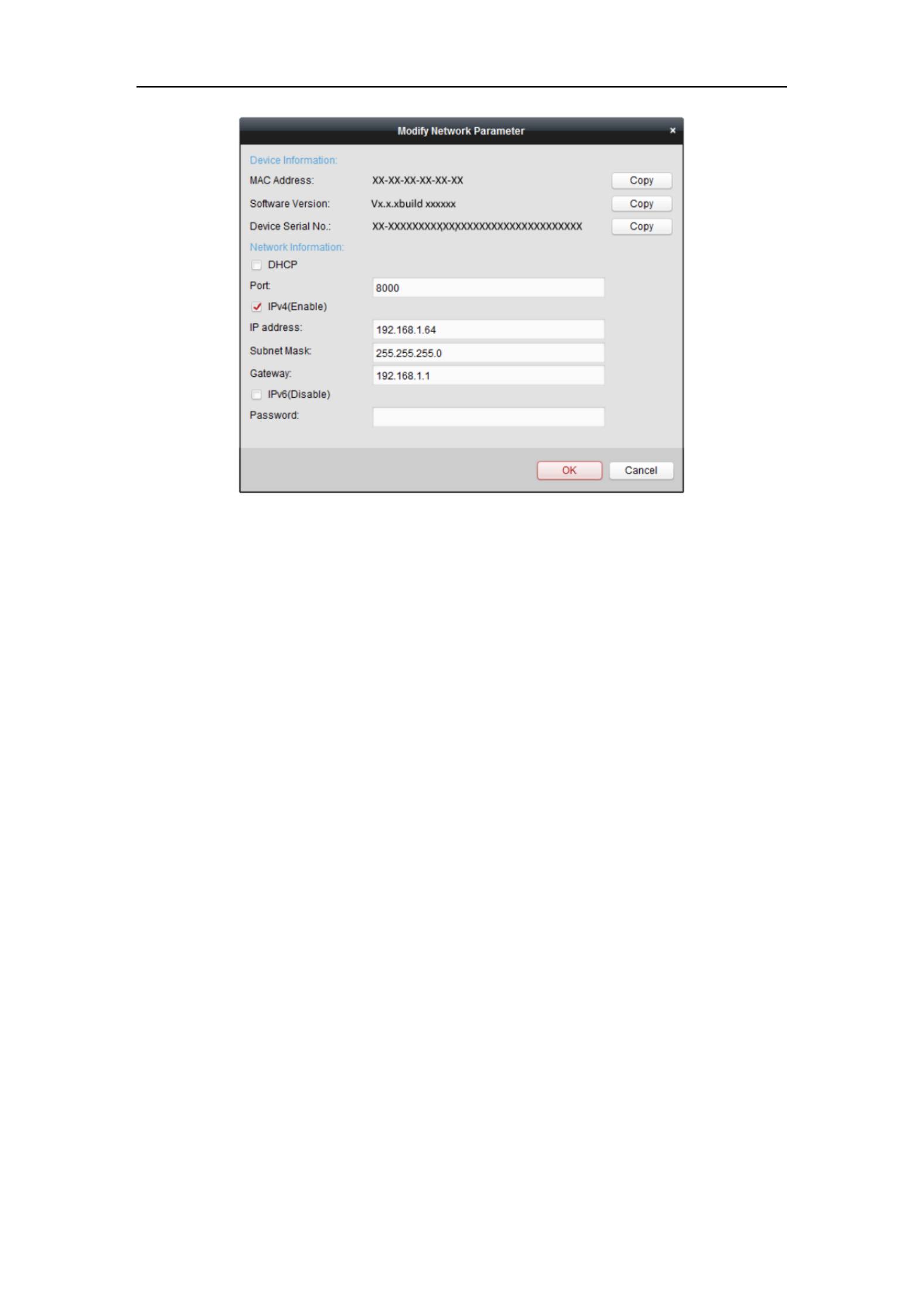
7. Click the Modify Netinfo button to pop up the Network Parameter Modification
interface, as shown in the figure below.
User Manual of Network Camera
18
Figure 2-9 Modifying the Network Parameters
8. Change the device IP address to the same subnet with your computer by either
modifying the IP address manually or checking the checkbox of Enable DHCP.
9. Input the password to activate your IP address modification.
2.2 Setting the Network Camera over the WAN
Purpose:
This section explains how to connect the network camera to the WAN with a static IP
or a dynamic IP.
2.2.1 Static IP Connection
Before you start:
Please apply a static IP from an ISP (Internet Service Provider). With the static IP
address, you can connect the network camera via a router or connect it to the WAN
directly.
Connecting the network camera via a router
Steps:
1. Connect the network camera to the router.
User Manual of Network Camera
19
2. Assign a LAN IP address, the subnet mask and the gateway. Refer to Section 2.1.2
for detailed IP address configuration of the network camera.
3. Save the static IP in the router.
4. Set port mapping, e.g., 80, 8000, and 554 ports. The steps for port mapping vary
according to the different routers. Please call the router manufacturer for
assistance with port mapping.
Note: Refer to Appendix 2 for detailed information about port mapping.
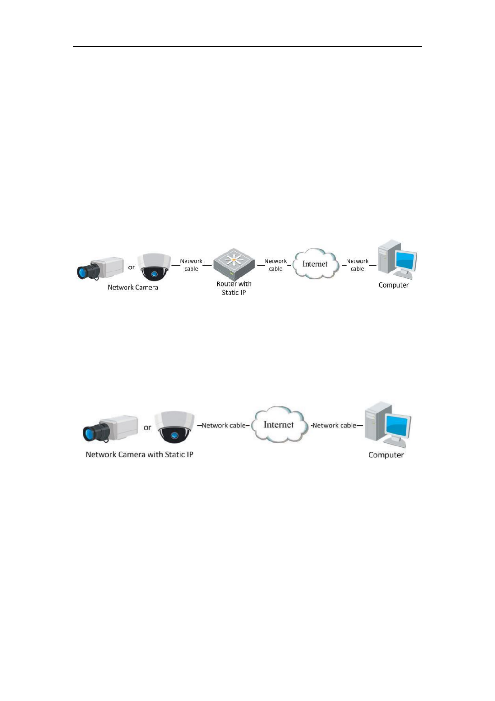
5. Visit the network camera through a web browser or the client software over the
internet.
Figure 2-10 Accessing the Camera through Router with Static IP
Connecting the network camera with static IP directly
You can also save the static IP in the camera and directly connect it to the internet
without using a route Refer to Section 2.1.2 for detailed IP address configuration of r.
the network camera.
Figure 2-11 Accessing the Camera with Static IP Directly
2.2.2 Dynamic IP Connection
Before you start:
Please apply a dynamic IP from an ISP. With the dynamic IP address, you can connect
the network camera a modem or a router. to
Connecting the network camera via a router
Steps:
User Manual of Network Camera
20
1. Connect the network camera to the router.
2. In the camera, assign a LAN IP address, the subnet mask and the gateway. Refer
to Section 2.1.2 for detailed IP address configuration of the network camera.
3. In the router, set the PPPoE user name, password and confirm the password.
4. Set port mapping. E.g. 80, 8000, and 554 ports. The steps for port mapping vary
depending on different routers. Please call the router manufacturer for assistance
with port mapping.
Note: Refer to Appendix 2 for detailed information about port mapping.
5. Apply a domain name from a domain name provider.
6. Configure the DDNS settings in the setting interface of the router.
7. Visit the camera via the applied domain name.
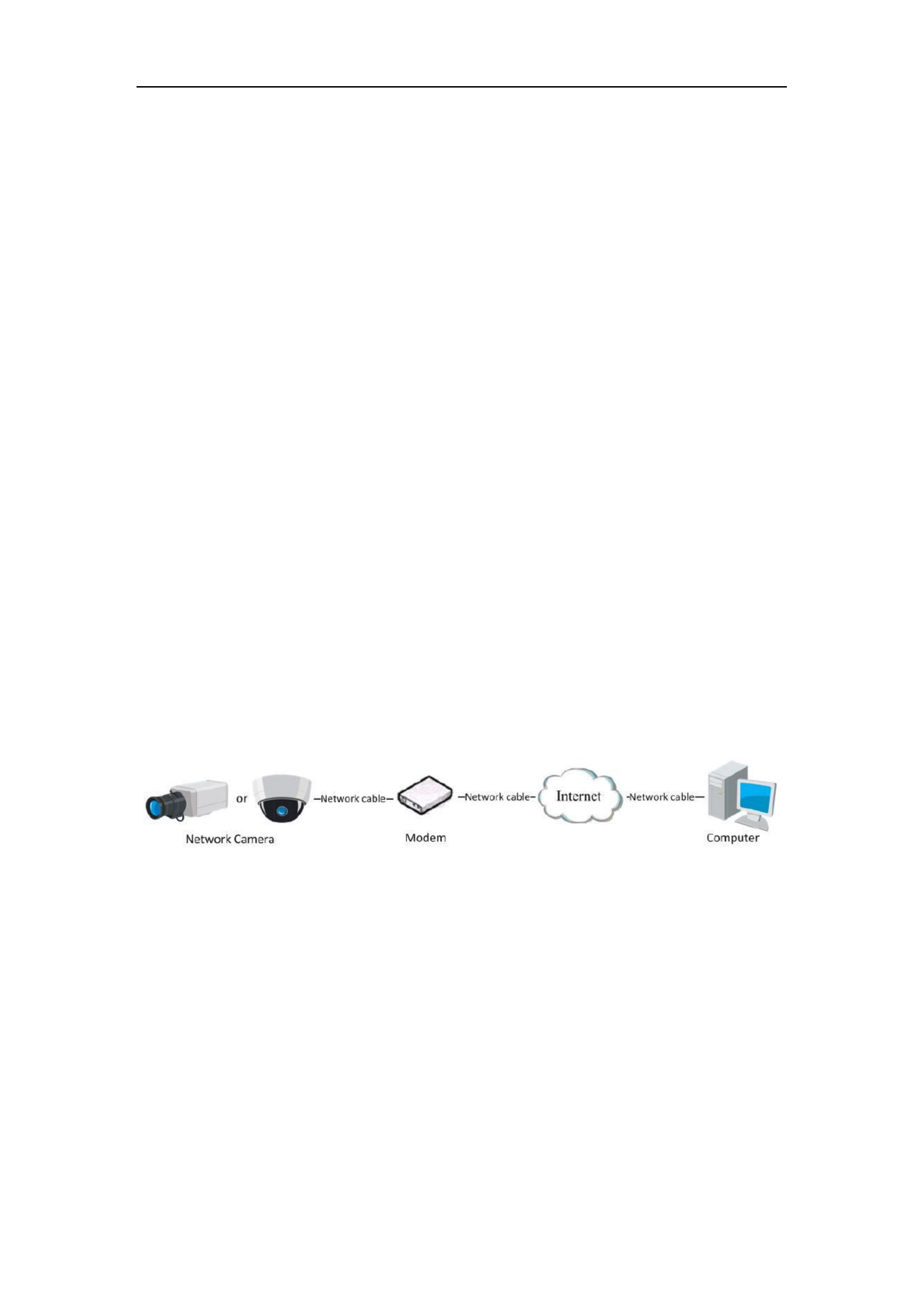
Connecting the network camera via a modem
Purpose:
This camera supports the PPPoE auto dial-up function. The camera gets a public IP
address by ADSL dial-up after the camera is connected to a modem. You need to
configure the PPPoE parameters of the network camera. Refer to Section 6.3.3
Configuring PPPoE Settings for detailed configuration.
Figure 2-12 Accessing the Camera with Dynamic IP
Note: The obtained IP address is dynamically assigned via PPPoE, so the IP address
always changes after rebooting the camera. To solve the inconvenience of the
dynamic IP, you need to get a domain name from the DDNS provider (E.g.
DynDns.com). Please follow the steps below for normal domain name resolution and
private domain name resolution to solve the problem.
Normal Domain Name Resolution
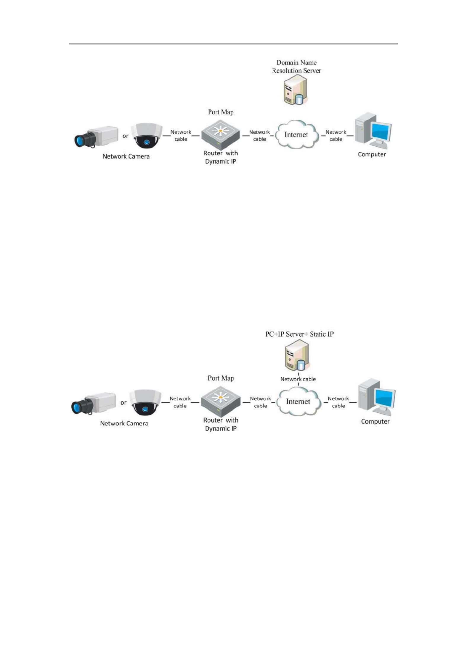
User Manual of Network Camera
21
Figure 2-13 Normal Domain Name Resolution
Steps:
1. Apply a domain name from a domain name provider.
2. Configure the DDNS settings in the interface of the network DDNS Settings
camera. Refer to for detailed Section 6.3.4 Configuring DDNS Settings
configuration.
3. Visit the camera via the applied domain name.
Private Domain Name Resolution
Figure 2-14 Private Domain Name Resolution
Steps:
1. Install and run the IP Server software in a computer with a static IP.
2. Access the network camera through the LAN with a web browser or the client
software.
3. Enable DDNS and select IP Server as the protocol type. Refer to Section 6.3.4
Configuring DDNS Settings for detailed configuration.

User Manual of Network Camera
22
Chapter 3 Access to the Network
Camera
3.1 Accessing by Web Browsers
Steps:
1. Open the web browser.
2. In the browser address bar, input the IP address of the network camera, and press
the key to enter the login interface. Enter
3. Activate the network camera for the first time using, refer to the section 2 .2 for .1
details.
Note:
The default IP address is 192.168.1.64.
If the camera is not activated, please activate the camera first according to
Chapter 3.1 or Chapter 3.2.
4. Select English as the interface language on the top-right of login interface.
5. Input the user name and password and click .
The admin user should configure the device accounts and user/operator permissions
properly. Delete the unnecessary accounts and user/operator permissions.
Note:
The device IP address gets locked if the admin user performs 7 failed password
attempts (5 attempts for the user/operator).
Figure 3-1 Login Interface

User Manual of Network Camera
23
6. Install the plug-in before viewing the live video and operating the camera. Please
follow the installation prompts to install the plug- . in
Figure 3-2 Download and Install Plug- in
Figure 3-3 Install Plug-in (1)
Figure 3-4 Install Plug-in (2)
Note: You may have to close the web browser to install the plug-in. Please reopen the

User Manual of Network Camera
24
web browser and log in again after installing the plug-in.
3.2 Accessing by Client Software
The product CD contains the iVMS-4200 client software. You can view the live video
and manage the camera with the software.
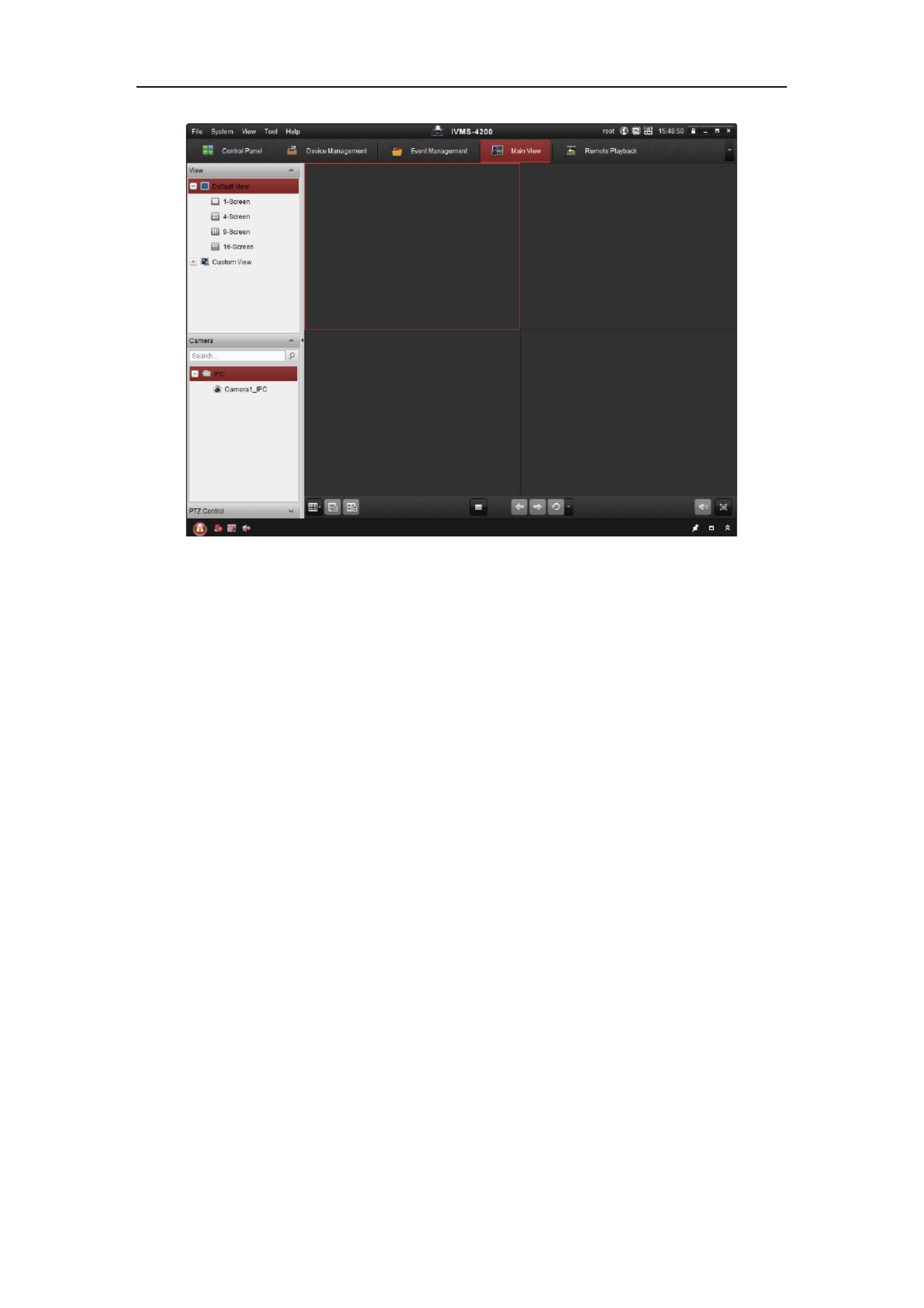
Follow the installation prompts to install the software. The control panel and live view
interface of iVMS-4200 client software are shown as below.
Figure 3-5 iVMS-4200 Control Panel
User Manual of Network Camera
25
Figure 3-6 iVMS-4200 Main View
Note: For detailed information about the software, please refer to the user manual of
the iVMS-4200.

User Manual of Network Camera
26
Chapter 4 -Fi Settings Wi
Purpose:
By connecting to the wireless network, you don’t need to use cable of any kind for
network connection, which is very convenient for the actual surveillance application.
Note: This chapter is only applicable for the cameras with the built-in Wi-Fi module.
4.1 Configuring Wi-Fi Connection in Manage and
Ad-hoc Modes
Before you start:
A wireless network must be configured.
Wireless Connection in Manage Mode
Steps:
1. Enter the Wi-Fi configuration interface.
Configuration> Advanced Configuration> Network> Wi- Fi
Figure 4-1 Wireless Network List
2. Click Search to search the online wireless connections.
3. Click to choose a wireless connection on the list.
Figure 4-2 -Fi Setting- Manage Mode Wi
User Manual of Network Camera
27
4. Check the checkbox to select the and the Network mode as Manage, Security
mode of the network is automatically shown when you select the wireless
network, please don’t change it manually.
Note: These parameters are exactly identical with those of the router.
5. Enter the key to connect the wireless network. The key should be that of the
wireless network connection you set on the router.
Wireless Connection in Ad-hoc Mode
If you choose the Ad-hoc mode, you don’t need to connect the wireless camera via a
router. The scenario is the same as you connect the camera and the PC directly with a
network cable.
Steps:
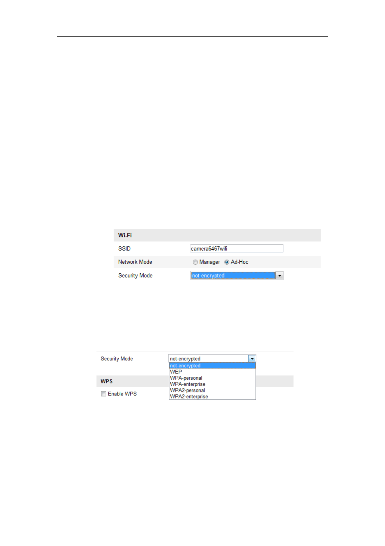
1. Choose Ad-hoc mode.
Figure 4-3 -Fi Setting- Wi Ad-hoc
2. Customize a SSID for the camera.
3. Choose the Security Mode of the wireless connection.
Figure 4-4 Security Mode- Ad-hoc Mode
4. able the wireless connection function for your PC. En
5. On the PC side, search the network and you can see the SSID of the camera
listed.

User Manual of Network Camera
28
Figure 4-5 -hoc Connection Point Ad
6. Choose the SSID and connect.
Security Mode Description:
Figure 4-6 Security Mode
You can choose the Security Mode as not-encrypted, WEP, WPA-personal,
WPA-enterprise, WPA2-personal, and WPA2-enterprise.
WEP mode:
Figure 4-7 WEP Mode
Authentication - Select Open or Shared Key System Authentication, depending on

User Manual of Network Camera
29
the method used by your access point. Not all access points have this option, in
which case they probably use Open System, which is sometimes known as SSID
Authentication.
Key length - This sets the length of the key used for the wireless encryption, 64 or
128 bit. The encryption key length can sometimes be shown as 40/64 and
104/128.
Key type - The key types available depend on the access point being used. The
following options are available:
HEX - Allows you to manually enter the hex key.
ASCII - In this method the string must be exactly 5 characters for 64-bit WEP
and 13 characters for 128-bit WEP.
WPA-personal and WPA2-personal Mode:
Enter the required Pre-shared Key for the access point, which can be a hexadecimal
number or a passphrase.
Figure 4-8 Security Mode- WPA-personal
WPA- enterprise and WPA2-enterprise Mode:
Choose the type of client/server authentication being used by the access point;
EAP-TLS or EAP-PEAP.
EAP-TLS

User Manual of Network Camera
30
Figure 4-9 EAP-TLS
Identity - Enter the user ID to present to the network.
Private key password Enter the password for your user ID. –
EAPOL version - Select the version used (1 or 2) in your access point.
CA Certificates - Upload a CA certificate to present to the access point for
authentication.
EAP-PEAP:
User Name - Enter the user name to present to the network
Password - Enter the password of the network
PEAP Version - Select the PEAP version used at the access point.
Label - Select the label used by the access point.
EAPOL version - Select version (1 or 2) depending on the version used at the
access point
CA Certificates - Upload a CA certificate to present to the access point for
authentication
For your privacy and to better protect your system against security risks, we
strongly recommend the use of strong passwords for all functions and network
devices. The password should be something of your own choosing (using a
minimum of 8 characters, including upper case letters, lower case letters,

User Manual of Network Camera
31
numbers and special characters) in order to increase the security of your product.
Proper configuration of all passwords and other security settings is the
responsibility of the installer and/or end-user.
4.2 Easy Wi-Fi Connection with WPS function
Purpose:
The setting of the wireless network connection is never easy. To avoid the complex
setting of the wireless connection you can enable the WPS function.
WPS (Wi-Fi Protected Setup) refers to the easy configuration of the encrypted
connection between the device and the wireless router. The WPS makes it easy to add
new devices to an existing network without entering long passphrases. There are two
modes of the WPS connection, the PBC mode and the PIN mode.
Note: If you enable the WPS function, you do not need to configure the parameters
such as the encryption type and you don’t need to know the key of the wireless
connection.
Steps:
Figure 4-10 -Fi Settings - WPS Wi
PBC Mode:
PBC refers to the Push-Button-Configuration, in which the user simply has to push a
button, either an actual or virtual one (as the button on the configuration
interface of the IE browser), on both the Access Point (and a registrar of the network)
and the new wireless client device.
1. Check the checkbox of to enable WPS.

User Manual of Network Camera
32
2. Choose the connection mode as PBC.
Note: Support of this mode is mandatory for both the Access Points and the
connecting devices.
3. Check on the Wi-Fi router to see if there is a WPS button. If yes push the button
and you can see the indicator near the button start flashing, which means the WPS
function of the router is enabled. For detailed operation, please see the user guide of
the router.
4. Push the WPS button to enable the function on the camera.
If there is not a WPS button on the camera, you can also click the virtual button to
enable the PBC function on the web interface.
5. Click button. Connect
When the PBC mode is both enabled in the router and the camera, the camera and the
wireless network is connected automatically.
PIN Mode:
The PIN mode requires a Personal Identification Number (PIN) to be read from either
a sticker or the display on the new wireless device. This PIN must then be entered to
connect the network, usually the Access Point of the network.
Steps:
1. Choose a wireless connection on the list and the SSID is shown.

User Manual of Network Camera
33
Figure 4-11 -Fi Settings WPS PIN Mode Wi –
2. Choose Use route PIN code.
If the PIN code is generated from the router side, you should enter the PIN code you
get from the router side in the Router PIN code field.
3. Click . Connect
Or
You can generate the PIN code on the camera side. And the expired time for the PIN
code is 120 seconds.
1. Click . Generate
2. Enter the code to the router, in the example, enter 48167581 to the route r.
4.3 IP Property Settings for Wireless Network
Connection
The default IP address of wireless network interface controller is 192.168.1.64. When
you connect the wireless network you can change the default IP.
Steps:

User Manual of Network Camera
34
1. Enter the TCP/IP configuration interface.
Configuration> Advanced Configuration> Network> TCP/IP
Or
Configuration> Basic Configuration> Network> TCP/IP
Figure 4-12 TCP/IP Settings
2. Select the NIC as wlan.
3. Customize the IPv4 address, the IPv4 Subnet Mask and the Default Gateway.
The setting procedure is the same with that of LAN.
If you want to be assigned the IP address you can check the checkbox to enable the
DHCP.
User Manual of Network Camera
35
Chapter 5 Live View
5.1 Live View Page
Purpose:
The live view page allows you to view the real-time video, capture images, realize
PTZ control, set/call presets and configure video parameters.
Log the network camera to enter the live view page, or you can click in Live View on
the menu bar of the main page to enter the live view page.
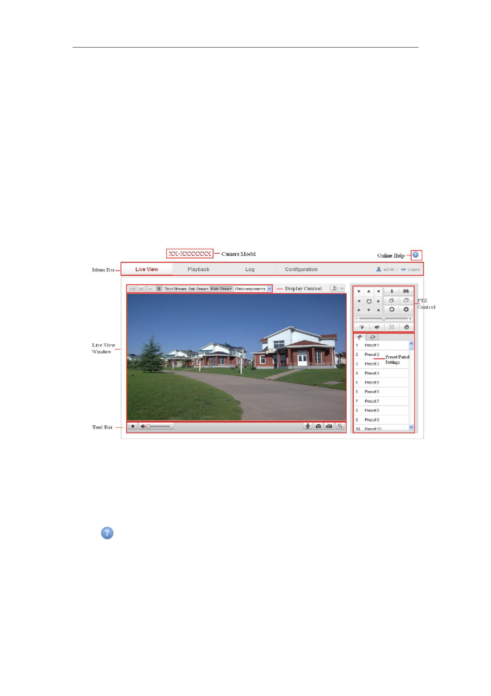
Descriptions of the live view page:
Figure 5-1 Live View Page
Camera Model:
It lists the camera model you are connecting to.
Online Help:
Click to get the online help, which will guide you through the basic operations for
each function.
Menu Bar:
Click each tab to enter Live View, Playback, Log and Configuration page
respectively.

User Manual of Network Camera
36
Display Control:
Click each tab to adjust the layout and the stream type of the live view. And you can
click the drop-down to select the plug-in. For IE (internet explorer) user,
webcomponents and quick time are selectable. And for Non-IE user, webcomponents,
quick time, VLC or MJPEG is selectable if they are supported by the web browser.
Live View Window:
Display the live video.
Toolbar:
Operations on the live view page, e.g., live view, capture, record, audio on/off,
two-way audio, etc.
PTZ Control:
Panning, tilting and zooming actions of the camera and the light and wiper control.
(only available for cameras supporting PTZ function)
Preset/Patrol Settings :
Set/call/delete the presets or patrols for PTZ cameras.
5.2 Starting Live View
In the live view window as shown in Figure 5-2, click on the toolbar to start the
live view of the camera.
Figure 5-2 Live View Toolbar
Table 5-1 Descriptions of the Toolbar
Icon
Description
/
Start/Stop live view.
The window size is 4:3.
The window size is 16:9.
The original widow size.
Self-adaptive window size.
Live view with the main stream.
Live view with the sub stream.
Live view with the third stream.

User Manual of Network Camera
37
Click to select the third-party plug-in.
Manually capture the picture.
/
Manually start/stop recording.
/
Audio on and adjust volume /Mute.
/
Turn on/off microphone.
/
Turn on/off digital zoom function.
/
Turn on/off 3D positioning function.
Note: The third stream and 3D positioning require the support of camera.
5.3 Recording and Capturing Pictures Manually
In the live view interface, click on the toolbar to capture the live pictures or
click to record the live view. The saving paths of the captured pictures and clips
can be set on the page. To configure remote Configuration > Local Configuration
scheduled recording, please refer to . Section 7.2
Note: The captured image will be saved as JPEG file or BMP file your computer. in
5.4 Operating PTZ Control
Purpose:
In the live view interface, you use the PTZ control buttons to realize pan/tilt/zoom can
control of the camera.
Note: To realize PTZ control, the camera connected to the network must support the
PTZ function or a pan/tilt unit has been installed to the camera. Please properly set the
PTZ parameters on RS-485 s tings page referring et to Section 12.9 .RS-485 Settings
5.4.1 PTZ Control Panel
On the live view page, click to show the PTZ control panel click to or
hide . it
Click the direction buttons to control the pan/tilt movements.
User Manual of Network Camera
38
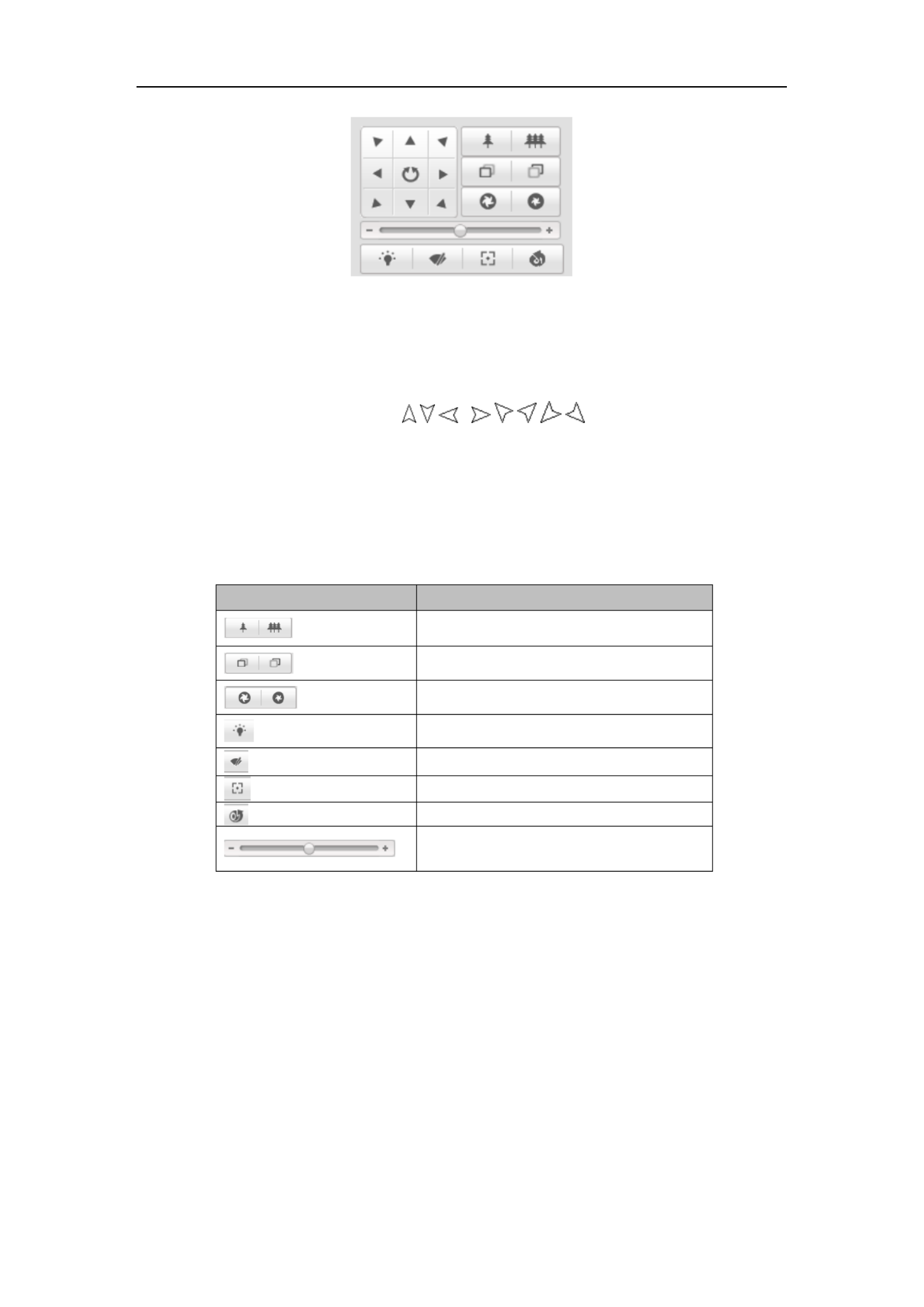
Figure 5-3 PTZ Control Panel
Click the zoom/iris/focus buttons to realize lens control.
Notes:
There are 8 direction arrows ( , , , , , , , ) in the live view window
when you click and drag the mouse in the relative positions.
For the cameras which support lens movements only, the direction buttons are
invalid.
Table 5-2 Descriptions of PTZ Control Panel
Icon
Description
Zoom in/out
Focus near/far
Iris / + -
Light on/off
Wiper on/off
Auxiliary focus
Initialize lens
Adjust speed of pan/tilt movements
5.4.2 Setting / Calling a Preset
Setting a Preset:
1. In the PTZ control panel, select a preset number from the preset list.

User Manual of Network Camera
39
Figure 5-4 Setting a Preset
2. Use the PTZ control buttons to move the lens the desired position. to
• Pan the camera to the right or left.
• Tilt the camera up or down.
• Zoom in or out.
• Refocus the lens.
3. Click to finish the setting of the current preset.
4. You can click to delete the preset.
Note: Up to 16 presets can be configured for the Network Mini PT Camera.
Calling a Preset:
This feature enables the camera to point to a specified preset scene manually or when
an event takes place.
For the defined preset, you can call it at any time to the desired preset scene.
In the PTZ control panel, select a defined preset from the list and click to call the
preset.
Or you can place the mouse on the presets interface, and call the preset by typing the
preset No. to call the corresponding presets.
Figure 5-5 Calling a Preset

User Manual of Network Camera
40
5.4.3 Setting / Calling a Patrol
Note:
No less than 2 presets have to be configured before you set a patrol.
Steps:
1. Click to enter the patrol configuration interface.
2. Select a path No., and click to add the configured presets.
3. Select the preset, and input the patrol duration and patrol speed.
4. Click OK to save the first preset.
5. Follow the steps above to add the other presets.
Figure 5-6 Add Patrol Path
6. Click to save a patrol.
7. Click to start the patrol, and click to stop it.
8. (Optional) Click to delete a patrol.

User Manual of Network Camera
41
Chapter 6 Network Camera
Configuration
6.1 Configuring Local Parameters
Note: The local configuration refers to the parameters of the live view, record files
and captured pictures. The record files and captured pictures are the ones you record
and captured using the web browser and thus the saving paths of them are on the PC
running the browser.
Steps:
1. Enter the Local Configuration interface:
Configuration > Local Configuration
Figure 6-1 Local Configuration Interface
2. Configure the following settings:
Live View Parameters: Set the protocol type and live view performance.
Protocol Type: TCP, UDP, MULTICAST and HTTP are selectable.
TCP: Ensures complete delivery of streaming data and better video quality,
yet the real-time transmission will be affected.

User Manual of Network Camera
42
UDP: Provides real-time audio and video streams.
HTTP: Allows the same quality as of TCP without setting specific ports for
streaming under some network environments.
MULTICAST: It’s recommended to select MCAST type when using the
Multicast function. For detailed information about Multicast, refer to Section
6.3.1 Configuring TCP/IP Settings.
Live View Performance: Set the live view performance to Shortest Delay or
Auto.
Rules: It refers to the rules on your local browser, select enable or disable to
display or not display the colored marks when the motion detection, face
detection, or intrusion detection is triggered. E.g.: enabled as the rules are, and
the face detection is enabled as well, when a face is detected, it will be marked
with a green rectangle on the live view.
Image Format: Choose the image format for picture capture.
Record File Settings: Set the saving path of the recorded video files. Valid for the
record files you recorded with the web browser.
Record File Size: Select the packed size of the manually recorded and
downloaded video files to 256M, 512M or 1G. After the selection, the
maximum record file size is the value you selected.
Save record files to: Set the saving path for the manually recorded video files.
Save downloaded files to: Set the saving path for the downloaded video files
in playback mode.
Picture and Clip Settings: Set the saving paths of the captured pictures and
clipped video files. Valid for the pictures you captured with the web browser.
Save snapshots in live view to: Set the saving path of the manually captured
pictures in live view mode.
Save snapshots when playback to: Set the saving path of the captured
pictures in playback mode.
Save clips to: Set the saving path of the clipped video files in playback mode.
Note: You can click Browse to change the directory for saving the clips and pictures.
User Manual of Network Camera
43
3. Click to save the settings. Save
6.2 Configuring Time Settings
Purpose:
You can follow the instructions in this section to configure the time synchronization
and DST settings.
Steps:
1. Enter the Time Settings interface:
Configuration > Basic Configuration > System > Time Settings
Or Configuration > Advanced Configuration > System > Time Settings
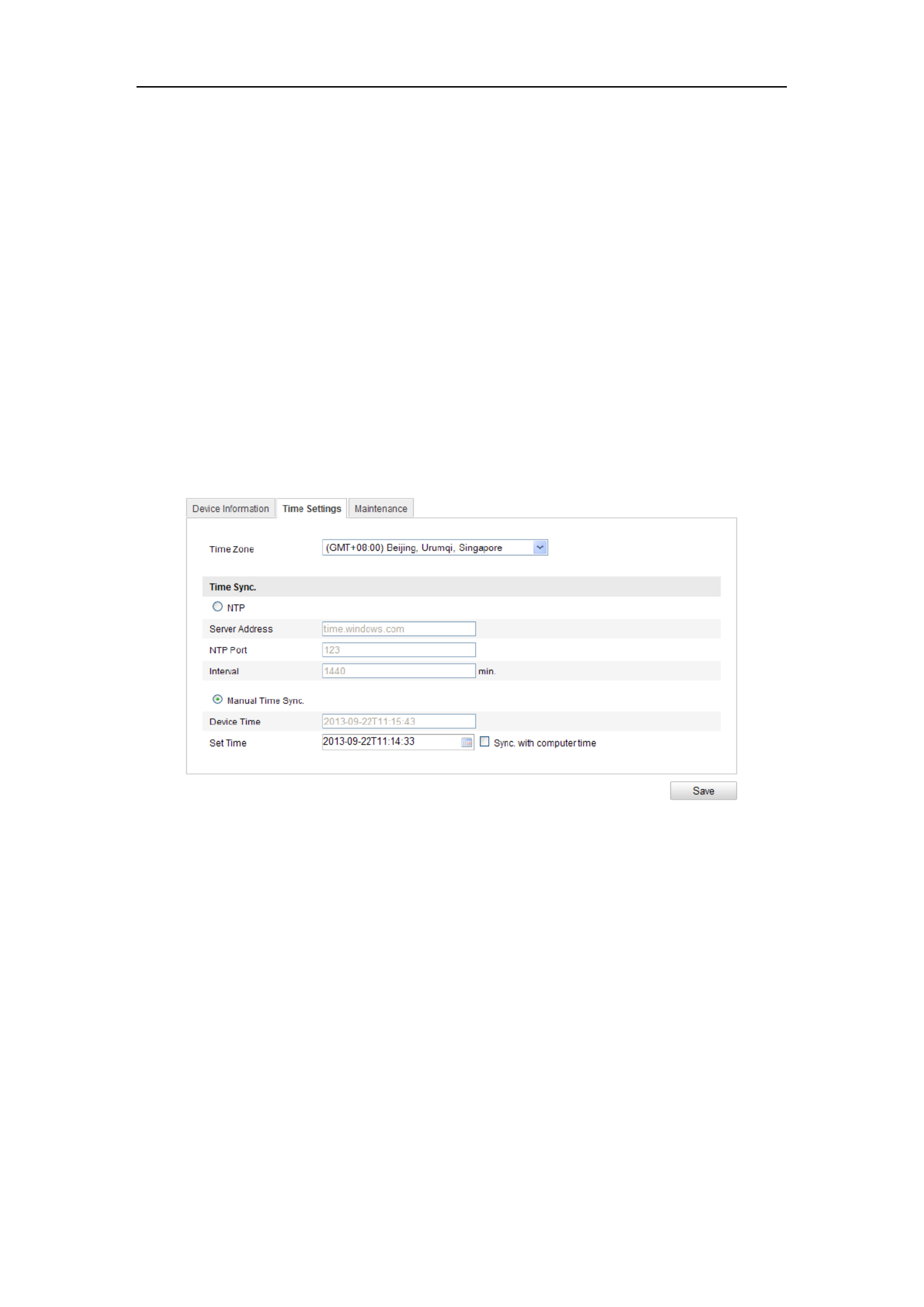
Figure 6-2 Time Settings
Select the Time Zone.
Select the Time Zone of your location from the drop-down menu.
Synchronizing Time by NTP Server.
(1) Check the checkbox to enable the function. NTP
(2) Configure the following settings:
Server Address: IP address of NTP server.
NTP Port: Port of NTP server.
Interval: The time interval between the two synchronizing actions with NTP
server.
User Manual of Network Camera
44
Figure 6-3 Time Sync by NTP Server
Note: If the camera is connected to a public network, you should use a NTP server
that has a time synchronization function, such as the server at the National Time
Center (IP Address: 210.72.145.44). If the camera is set in a customized network,
NTP software can be used to establish a NTP server for time synchronization.
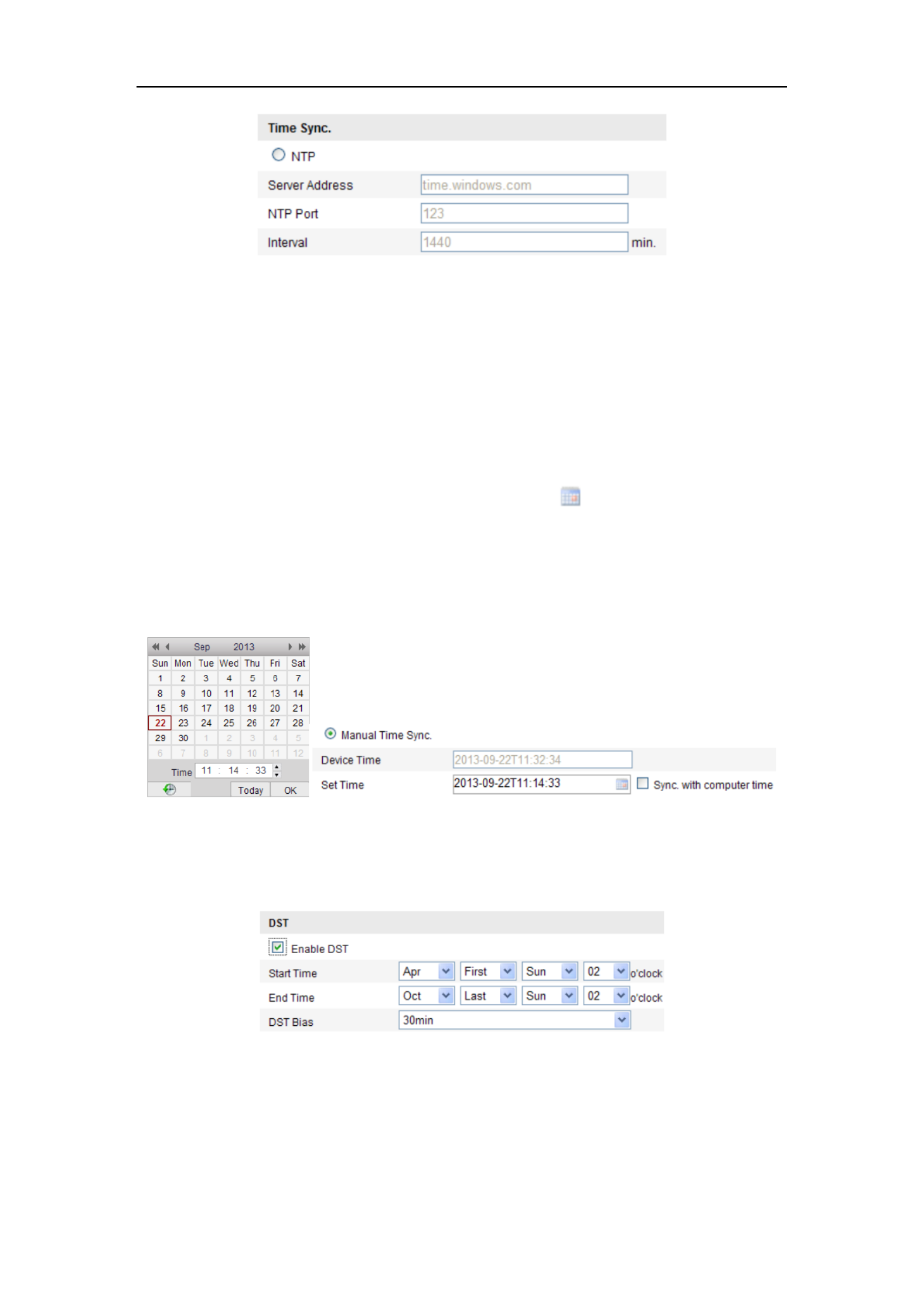
Synchronizin Time Synchronization Manually g
Enable the Manual Time Sync function and then click to set the system time
from the pop-up calendar.
Note: You can also check the Sync with computer time checkbox to synchronize the
time of the camera with that of your computer.
Figure 6-4 Time Sync Manually
Click the tab page to enable the DST function and Set the date of the DST DST
period.
Figure 6-5 DST Settings
2. Click to save the settings. Save

User Manual of Network Camera
45
6.3 Configuring Network Settings
6.3.1 Configuring TCP/IP Settings
Purpose:
TCP/IP settings must be properly configured before you operate the camera over
network. The camera supports both the IPv4 and IPv6. Both versions may be
configured simultaneously without conflicting to each other, and at least one IP
version should be configured.
Steps:
1. Enter TCP/IP Settings interface:
Configuration > Basic Configuration > Network > TCP/IP
Or Configuration > Advanced Configuration > Network > TCP/IP
Figure 6-6 TCP/IP Settings
2. Configure the basic network settings, including the NIC Type, IPv4 or IPv6
Address, IPv4 or IPv6 Subnet Mask, IPv4 or IPv6 Default Gateway, MTU settings

User Manual of Network Camera
46
and Multicast Address.
3. (Optional) Check the checkbox of , and then the Enable Multicast Discovery
online network camera can be automatically detected by client software via
private multicast protocol in the LAN.
4. Click to save the above settings Save .
Notes :
The valid value range of MTU is 1280 ~ 1500.
The Multicast sends a stream to the multicast group address and allows multiple
clients to acquire the stream at the same time by requesting a copy from the
multicast group address. Before utilizing this function, you have to enable the
Multicast function of your router.
A reboot is required for the settings to take effect.
6.3.2 Configuring Port Settings
Purpose:
You can set the port No. of the camera, e.g. HTTP port, RTSP port and HTTPS port.
Steps:
1. Enter the Port Settings interface:
Configuration > Basic Configuration > Network > Port
Or Configuration > Advanced Configuration > Network > Port
Figure 6-7 Port Settings
2. Set the HTTP port, RTSP port, HTTPS port and server port of the camera.
HTTP Port: The default port number is 80, and it can be changed to any port No.
which is not occupied.
RTSP Port: The default port number is 554 and it can be changed to any port No.

User Manual of Network Camera
47
ranges from 1024 to 65535.
HTTPS Port: The default port number is 443, and it can be changed to any port
No. which is not occupied.
Server Port: The default server port number is 8000, and it can be changed to
any port No. ranges from 2000 to 65535.
3. Click to save the settings. Save
Note: A reboot is required for the settings to take effect.
6.3.3 Configuring PPPoE Settings
Steps:
1. Enter the PPPoE Settings interface:
Configuration >Advanced Configuration > Network > PPPoE
Figure 6-8 PPPoE Settings
2. Check the checkbox to enable this feature. Enable PPPoE
3. Enter , , and password for PPPoE access. User Name Password Confirm
Note: The User Name and Password should be assigned by your ISP.
For your privacy and to better protect your system against security risks, we
strongly recommend the use of strong passwords for all functions and network
devices. The password should be something of your own choosing (using a
minimum of 8 characters, including upper case letters, lower case letters,
numbers and special characters) in order to increase the security of your product.
Proper configuration of all passwords and other security settings is the
responsibility of the installer and/or end-user.
4. Click to save and exit the interface. Save

User Manual of Network Camera
48
Note: A reboot is required for the settings to take effect.
6.3.4 Configuring DDNS Settings
Purpose:
If your camera is set to use PPPoE as its default network connection, you can use the
Dynamic DNS (DDNS) for network access.
Before you start:
Registration on the DDNS server is required before configuring the DDNS settings of
the camera.
For your privacy and to better protect your system against security risks, we
strongly recommend the use of strong passwords for all functions and network
devices. The password should be something of your own choosing (using a
minimum of 8 characters, including upper case letters, lower case letters,
numbers and special characters) in order to increase the security of your product.
Proper configuration of all passwords and other security settings is the
responsibility of the installer and/or end-user.
Steps:
1. Enter the DDNS Settings interface:
Configuration > Advanced Configuration > Network > DDNS
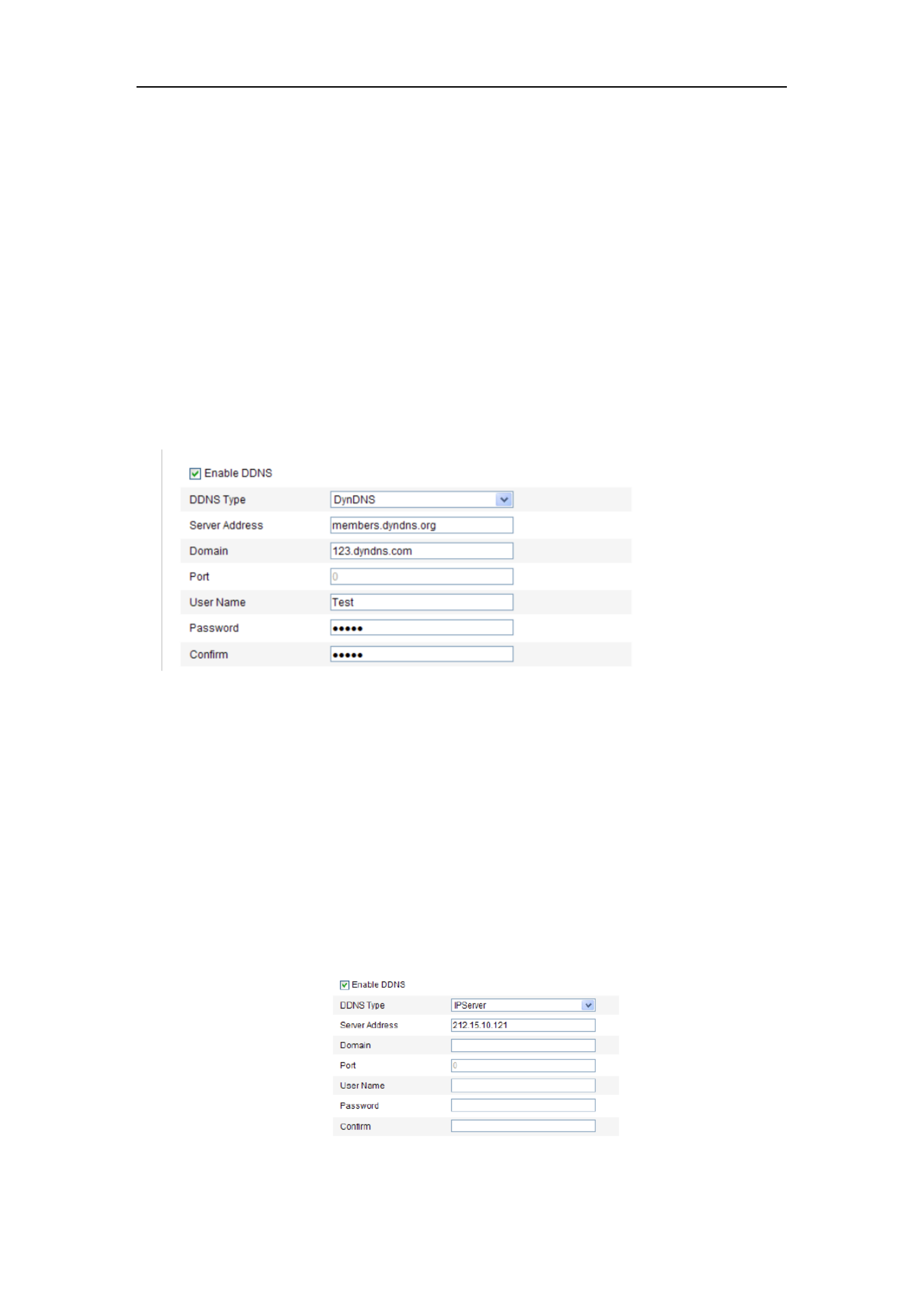
Figure 6-9 DDNS Settings
2. Check the checkbox to enable this feature. Enable DDNS
3. Select . Four DDNS types are selectable: HiDDNS, IPServer, -IP, DDNS Type NO
User Manual of Network Camera
49
and DynDNS.
DynDNS:
Steps:
(1) Enter of DynDNS (e.g. members.dyndns.org). Server Address
(2) In the text field, enter the domain name obtained from the DynDNS Domain
website.
(3) Enter the of DynDNS server. Port
(4) Enter the and registered on the DynDNS website. User Name Password
(5) Click to save the settings. Save
Figure 6-10 DynDNS Settings
IP Server:
Steps:
(1) Enter the Server Address of the IP Server.
(2) Click to save the settings. Save
Note: For the IP Server, you have to apply a static IP, subnet mask, gateway and
preferred DNS from the ISP. The should be entered with the Server Address
static IP address of the computer that runs the IP Server software.
Figure 6-11 IPServer Settings
User Manual of Network Camera
50
Note: For the US and Canada area, you can enter 173.200.91.74 as the server
address.
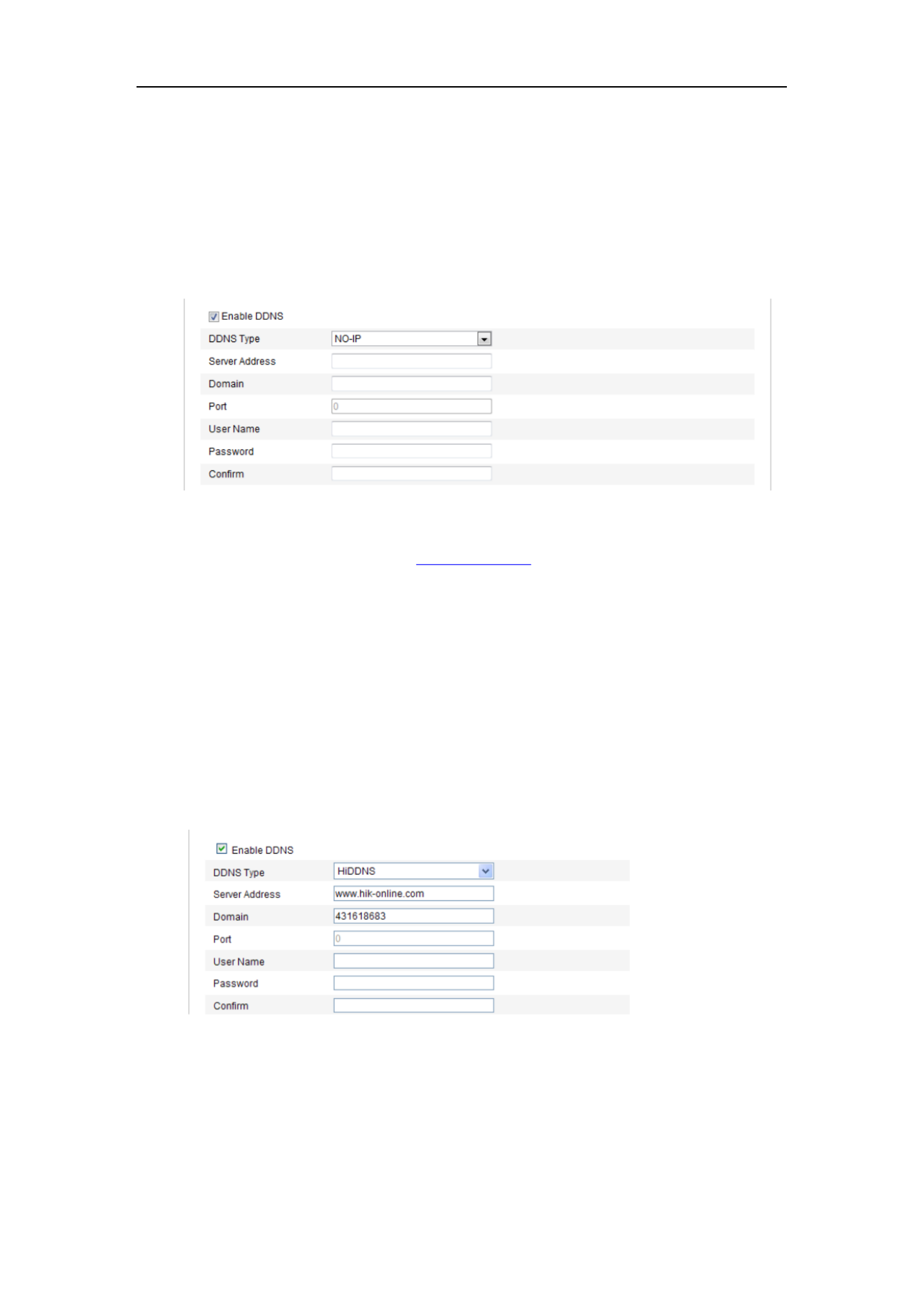
NO-IP:
Steps:
(1) Choose the DDNS Type as NO-IP.
Figure 6-12 -IP Settings NO
(2) Enter the Server Address as www.noip.com
(3) Enter the Domain name you registered.
(4) Enter the Port number, if needed.
(5) Enter the User Name and Password.
(6) Click and then you can view the camera with the domain name. Save
HiDDNS
Steps:
(1) Choose the DDNS Type as HiDDNS.
Figure 6-13 HiDDNS Settings
(2) Enter the Server Address www.hik-online.com.
(3) Enter the Domain name of the camera. The domain is the same with the
device alias in the HiDDNS server.

User Manual of Network Camera
100
1. Enter the Line Crossing Detection settings interface:
Configuration> Advanced Configuration> Sma Event> Line Crossing rt
Detection
2. Check the checkbox of to enable the function. Enable Line Crossing Detection
3. Select the line from the drop-down list for detection settings.
4. Click the button, and a virtual line is displayed on the live video. Draw Area
5. ick-and-drag the line, and you can locate it on the live video as desired. Click Cl
on the line, two red squares are displayed on each end, and you can
click-and-drag one of the red squares to define the shape and length of the line.
6. Select the direction for line crossing detection. And you can select the directions
as A<->B, A ->B, and B->A.
A<->B: Only the arrow on the B side shows; when an object going across the plane
with both direction can be detected and alarms are triggered.
A->B: Only the object crossing the configured line from the A side to the B side
can be detected.
B->A: Only the object crossing the configured line from the B side to the A side
can be detected.
7. Click-and-drag the slider to set the detection sensitivity.
Sensitivity: Range [1-100]. The higher the value is, the more easily the line
crossing action can be detected.
8. Repeat the above steps to configure other lines. Up to 4 lines can be set. You can
click the button to clear all pre-defined lines. Clear
9. Click the button to set the arming schedule. Edit
10. Select the linkage methods for line crossing detection, including Notify
Surveillance Center, Send Email, Upload to FTP, Trigger Channel and Trigger
Alarm Output.
11. Click to save the settings. Save

User Manual of Network Camera
101
Figure 6-62 Draw Crossing Line
6.6.12 Configuring Intrusion Detection
Purpose:
Intrusion detection function detects people, vehicle or other objects which enter and
loiter in a pre-defined virtual region, and some certain actions can be taken when the
alarm is triggered.
Note: Intrusion detection function varies according to different camera models.
Steps:
1. Enter the Intrusion Detection settings interface:
Configuration> Advanced Configuration> Smart Event> Intrusion Detection
2. Check the checkbox of to enable the function. Enable Intrusion Detection
3. Select the region from the drop-down list for detection settings.
4. Click the button to start the region drawing. Draw Area
5. Click on the live video to specify the four vertexes of the detection region, and
right click to complete drawing.

User Manual of Network Camera
102
6. Set the time threshold, detection sensitivity and object percentage for intrusion
detection.
Threshold: Range [0s-10s], the threshold for the time of the object loitering in
the region. If you set the value as 0, alarm is triggered immediately after the
object entering the region.
Sensitivity: Range [1-100]. The value of the sensitivity defines the size of the
object which can trigger the alarm. When the sensitivity is high, a very small
object can trigger the alarm.
Percentage: Range [1-100]. Percentage defines the ratio of the in-region part of
the object which can trigger the alarm. For example, if the percentage is set as
50%, when the object enters the region and occupies half of the whole region, the
alarm is triggered.
7. Repeat the above steps to configure other regions. Up to 4 regions can be set. You
can click the button to clear all pre-defined regions. Clear
8. Click the button to set the arming schedule. Edit
9. Select the linkage methods for intrusion detection, including Notify Surveillance
Center, Send Email, Upload to FTP, Trigger Channel and Trigger Alarm Output.
10. Click to save the settings. Save
Figure 6-63 Configuring Intrusion Area

User Manual of Network Camera
103
6.6.13 Configuring Region Entrance Detection
Purpose:
Region entrance detection function detects people, vehicle or other objects which
enter a pre-defined virtual region from the outside place, and some certain actions can
be taken when the alarm is triggered.
Note: Region entrance detection function varies according to different camera models.
Steps:
1. Enter the Region Entrance Detection settings interface:
Configuration> Advanced Configuration> Smart Event> Region Entrance
Detection
2. Check the checkbox of Enable Region Entrance Detection to enable the
function.
3. Select the region from the drop-down list for detection settings.
4. Click the button to start the region drawing. Draw Area
5. Click on the live video to specify the four vertexes of the detection region, and
right click to complete drawing.
6. Click-and-drag the slider to set the detection sensitivity.
Sensitivity: Range [1-100]. The value of the sensitivity defines the size of the
object which can trigger the alarm. When the sensitivity is high, a very small
object entering the region can trigger the alarm.
7. Repeat the above steps to configure other regions. Up to 4 regions can be set. You
can click the Clear button to clear all pre-defined regions.
8. Click the button to set the arming schedule. Edit
9. Select the linkage methods for region entrance detection, including Notify
Surveillance Center, Send Email, Upload to FTP, Trigger Channel and Trigger
Alarm Output.
10. Click to save the settings. Save

User Manual of Network Camera
105
object which can trigger the alarm. When the sensitivity is high, a very small
object exiting from the region can trigger the alarm.
7. Repeat the above steps to configure other regions. Up to 4 regions can be set. You
can click the button to clear all pre-defined regions. Clear
8. Click the button to set the arming schedule. Edit
9. Select the linkage methods for region exiting detection, including Notify
Surveillance Center, Send Email, Upload to FTP, Trigger Channel and Trigger
Alarm Output.
10. Click to save the settings. Save
Figure 6-65 Configuring Region Exiting Detection
6.6.15 Configuring Unattended Baggage Detection
Purpose:
Unattended baggage detection function detects the objects left over in the pre-defined
region such as the baggage, purse, dangerous materials, etc., and a series of actions
can be taken when the alarm is triggered.
Note: Unattended baggage detection function varies according to different camera
models.
Steps:

User Manual of Network Camera
106
1. Enter the Unattended Baggage Detection settings interface:
Configuration> Advanced Configuration> Smart Event> Unattended
Baggage Detection
2. Check the checkbox of to enable the Enable Unattended Baggage Detection
function.
3. Select the region from the drop-down list for detection settings.
4. Click the button to start the region drawing. Draw Area
5. Click on the live video to specify the four vertexes of the detection region, and
right click to complete drawing.
6. Set the time threshold and detection sensitivity for unattended baggage detection.
Threshold: Range [5s- s], the threshold for the time of the objects left over in 20
the region. If you set the value as 10, alarm is triggered after the object is left and
stay in the region for 10s.
Sensitivity: Range [1-100]. The value of sensitivity defines the similarity degree
of the background image. Usually, when the sensitivity is high, a very small
object left in the region can trigger the alarm.
7. Repeat the above steps to configure other regions. Up to 4 regions can be set. You
can click the button to clear all pre-defined regions. Clear
8. Click the button to set the arming schedule. Edit
9. Select the linkage methods for unattended baggage detection, including Notify
Surveillance Center, Send Email, Upload to FTP, Trigger Channel and Trigger
Alarm Output.
10. Click to save the settings. Save

User Manual of Network Camera
107
Figure 6-66 Configuring Unattended Baggage
6.6.16 Configuring Object Removal Detection
Purpose:
Object removal detection function detects the objects removed from the pre-defined
region, such as the exhibits on display, and a series of actions can be taken when the
alarm is triggered.
Note: Object removal detection function varies according to different camera models.
Steps:
1. Enter the Object Removal Detection settings interface:
Configuration> Advanced Configuration> Smart Event> Object Removal
Detection
2. Check the checkbox of to enable the Enable Object Removal Detection
function.
3. Select the region from the drop-down list for detection settings.
4. Click the button to start the region drawing. Draw Area
5. Click on the live video to specify the four vertexes of the detection region, and
right click to complete drawing.

User Manual of Network Camera
108
6. Set the time threshold and detection sensitivity for object removal detection.
Threshold: Range [5s-20 , the threshold for the time of the objects removed s]
from the region. If you set the value as 10, alarm is triggered after the object
disappears from the region for 10s.
Sensitivity: Range [1-100]. The value of sensitivity defines the similarity degree
of the background image. Usually, when the sensitivity is high, a very small
object taken from the region can trigger the alarm.
7. Repeat the above steps to configure other regions. Up to 4 regions can be set. You
can click the button to clear all pre-defined regions. Clear
8. Click the button to set the arming schedule. Edit
9. Select the linkage methods for object removal detection, including Notify
Surveillance Center, Send Email, Upload to FTP, Trigger Channel and Trigger
Alarm Output.
10. Click to save the settings. Save
Figure 6-67 Configuring Object Removal Detection

User Manual of Network Camera
109
6.7 VCA Configuration
6.7.1 Behavior Analysis
The behavior analysis detects a series of suspicious behavior, and certain linkage
methods will be enabled if the alarm is triggered.
Figure 6-68 Behavior Analysis
VCA Info
Behavior Analysis Version: It lists the version of the algorithms library.
Display information includes the display on picture and display on stream.
Display Target info. on Alarm Picture: There will be a fram on the target on e
the uploaded alarm picture if the checkbox is checked.
Display Rule info. on Alarm Picture: The captured target and the configured
area will be framed on the alarm picture.
Display VCA info. on Stream: The green frames will be displayed on the target
if in a live view or playback.
Note: Make sure the rules are enabled in your local settings. Go to
Configuration Local Configuration Rules > > to enable it.
Snapshot Setting: You can set the quality and resolution for the captured picture.
Upload JPEG Image to Center: Check the checkbox to upload the captured

User Manual of Network Camera
110
image to the surveillance center when a VCA alarm occurs.
Picture Quality: High, Medium and Low are selectable.
Picture Resolution: CIF, 4CIF, 720P, and 1080P are selectable.
Camera Calibration
Perform the following steps to three-dimensionally measure and quantize the image
from the camera, and then calculate the size of every target. The VCA detection will
be more accurate if the camera calibration is configured.
Steps:
1. Check the checkbox of to enable this function. Camera Calibration
2. Select the calibration mode as Input Basic Data or Draw on Live View Video.
Input Basic Data: Input the mounting height, viewing angle, and horizon
ratio of the camera manually.
Draw on Live View Video Draw Verification Line (Horizontal) : Click /
(Vertical) to draw a horizontal/vertical line in the live view, and input the
actual length in Real Length field. With the drawn reference lines and their
real length, the camera can conclude other objects appear in the live view.
3. (Optional) Check the checkbox of Enable Verification of Camera
Calibration Horizontal Verify / Vertical Verify, click the button to draw a
horizontal / vertical line on the live video, and then click the button Calibrate
to calculate the line length. Compare the calculated line length to the actual
length to verify the calibration information you set.
4. You can click to delete the drawn lines. Delete
5. Click to save the settings. Save
Note: If the live view is stopped, the camera calibration is invalid.

User Manual of Network Camera
112
3. Click to save the settings. Save
Rule
The behavior analysis supports a series of behaviors, including line crossing
detection, intrusion, region entrance, and region exiting, etc.
Note: Please refer to each chapter for detailed information of each behavior.
Figure 6-70 Configure the Rule

User Manual of Network Camera
113
Steps:
1. Click Tab to enter the rule configuration interface. Rule
2. Check the checkbox of the single rule to enable the rule for behavior analysis.
3. Select the rule type, set the filter type, and then draw the line / area on the live
video for the single rule.
Filter type: Pixels and Actual Size are selectable. If Pixels is selected, draw
the area of maximum size and minimum size on the live video for each rule.
If Actual Size is selected, input the length and width of the maximum size and
minimum size. Only the target whose size is between the minimum value and
maximum value will trigger the alarm.
Note: Make sure the camera calibration is configured if actual size is selected.
Detection Target: Select Human or Vehicle as the detection target. You can
also select All to detect all the objects as the target.
Draw line / area: For line crossing detection, you have to draw a line, and
select the crossing direction, which is bidirectional, A- -B, or B- -A. For to to
other events such as intrusion, region entrance, region exiting, etc., you have
to left click on the live video to set the end points of the area and right click to
finish the area drawing.
Note: If the live view is stopped, the detection area / line cannot be draw and
the rules cannot be set.
4. Check the checkbox of the combined rule to enable the rule for behavior
analysis.
5. Select two configured single rules as the Rule A and Rule B of the combined
rule, set the minimum and maximum time interval for the two single rules,
and then select the trigger order of the single rules for alarm filtering.
Notes:
If you select the rule type as None, the rule option is invalid, and no
behavior analysis can be configured.
The trigger order of the single rules for alarm filtering can be set as In
Ascending Order or In Ascending/Descending Order.
Up to 8 single rules and 2 combined rules are configurable. And the line
crossing, intrusion, region exiting and region entrance are supported for
the combined rules.

User Manual of Network Camera
114
6. Click to save the settings. Save
7. Click tab, click to set the schedule time for each rule, Arming Schedule Edit
and click to save the settings. Save
8. Click tab, check the checkbox of corresponding linkage Alarm Linkage
method for each rule, and click to save the settings. Save
Advanced Configuration
● Parameter
Configure the following parameters to detail the configuration.
Figure 6-71 Advanced Configuration
Detection Sensitivity [0~4]: Refers to the sensitivity of the camera detects a target.
The higher the value, the easier a target be recognized, and the higher the
misinformation is. The default value of 3 is recommended.
Background Update Rate [0~4]: It refers to the speed of the new scene replaces the
previous scene. The default value of 3 is recommended.
Single Alarm : If single alarm is selected, the target in the configured area will trigger
the alarm for only once. If it is not checked, the same target will cause the continuous
alarm in the same configured area.
Leave Interference Suppression: Check this checkbox to stop the interference
caused by the leaves in the configured area.
Output Type: Select the position of the frame. Target center, bottom center, and top
centers are selectable. E.g.: The target will be in the center of the frame if target center
is selected.

User Manual of Network Camera
115
Restore Default: Click to restore the configured parameters to the default.
Restart VCA: Restart the algorithms library of behavior analysis.
● Global Size Filter
Note: Compared with the size filter under rule, which is aiming at each
rule, the global size filter is aim at all rules.
Steps:
1. Check the checkbox of to enable the function. Global Size Filter
2. Select the Filter Type as Actual Size or Pixel.
Actual Size: Input the length and width of both the maximum size and the
minimum size. Only the target whose size is between the minimum value and
maximum value will trigger the alarm.
Notes:
● Camera calibration has to be configured if you select the filter by actual
size.
● The length of the maximum size should be longer than the length of the
minimum size, and so does the width.
Pixel: Click Minimum Size to draw the rectangle of the min. size on the live view.
And click Maximum Size to draw the rectangle of the max. size on the live view.
The target is smaller than the min. size or larger than the max. size will be
filtered.
Notes:
● The drawn area will be convert to the pixel by the background ed
algorithm.
● The global size filter cannot be configured if the live view is stopped.
● The length of the maximum size should be longer than the length of the
minimum size, and so does the width.
3. Click to save the settings. Save

User Manual of Network Camera
116
6.7.2 Face Capture
Face capture can capture the face appears in the configured area, and the face
characters information, including the age, gender, and wearing glasses or not will be
uploaded with the captured picture as well.
Figure 6-72 Face Capture
VCA Info
Face Capture Version: It lists the version of the algorithms library.
Display information includes the display on picture and display on stream.
Display Target info. on Alarm Picture: There will be a frame on the target on
the uploaded alarm picture if the checkbox is checked.
Display VCA info. on Stream: The green frames will be displayed on the target
if in a live view or playback.
Snapshot Setting: Select the picture quality for the captured picture. Good, better, and
best are selectable.
Shield Region
The shield region allows you to set the specific region in which the face capture will
not function. Up to 4 shield regions are supported.
Steps:
1. Click tab to enter the shield region configuration interface. Shield Region
2. Click Draw Area. Draw area by left click four end-points in the live view
window, and right click to finish the area drawing.

User Manual of Network Camera
118
recommended.
Capture Interval [1~255 Frame]: The frame interval to capture a picture. If you set
the value as 1, which is the default value, it means the camera captures the face in
every frame.
Capture Sensitivity [0~20]: The threshold the camera treats the target as a face. Only
when the face score generated by the algorithm is equal or higher than the value, the
camera will treat the target as a face. The default value of 2 is recommended.
Face Capture Advanced Parameters:
Face Exposure: Check the checkbox to enable the face exposure.
Reference Brightness [0~100]: The reference brightness of a face in the face
exposure mode. If a face is detected, the camera adjusts the face brightness according
to the value you set. The higher the value, the brighter the face is.
Minimum Duration [1~60min]: The minimum duration of the camera exposures the
face. The default value is 1 minute.
Note: If the face exposure is enabled, please make sure the WDR function is disabled,
and the manual iris is selected.
Enable Face ROI: If the camera captures a face, the face area will be treated as the
region of interest, and the image quality of this area will be improved.
Restore Default Restore : Click to restore all the settings in advanced configuration
to the factory default.

User Manual of Network Camera
119
Figure 6-73 Advanced Configuration
6.7.3 Heat Map
Heat map is a graphical representation of data represented by colors. The heat map
function of the camera usually be used to analyze the visit times and dwell time of
customers in a configured area.
Heat Map Configuration
Steps:
1. Enter the Heat Map configuration interface: Configuration > Advanced
Configuration > Heat Map

User Manual of Network Camera
123
Steps:
1. Enter the People Counting Configuration interface:
Configuration > Advanced Configuration > People Counting
2. Select tab to set the detailed parameters. People Counting Configuration
Figure 6-76 People Counting Configuration
3. Check the checkbox of to enable the function. Enable People Counting
4. (Optional) Check the checkbox of , and the real-time Enable OSD Overlay
number of people entered and exited is displayed on the live video.
5. t the detection line. Se
An orange line, called detection line can be set on the live video, and the
people entering or exiting through the line will be detected and counted.
1) Click , and an orange detection line will appear on the image. Draw Line
2) Click-and-drag the detection line to adjust its position.
3) Click-and-drag the two end points of the detection line to adjust its length.
4) To delete the detection line, click the button. Delete Line
Note: The detection line should cover the whole entrance / exit.
6. An arrow indicating the entering direction of people is shown after the

User Manual of Network Camera
125
Figure 6-77 Statistics Result
Note: It is recommended that you do not adjust the electronic lens after the
installation is completed, which may cause the inaccuracy of the data in some degree.

User Manual of Network Camera
126
Chapter 7 Storage Settings
Before you start:
To configure record settings, please make sure that you have the network storage
device within the network or the SD card inserted in your camera.
7.1 Configuring NAS Settings
Before you start:
The network disk should be available within the network and properly configured to
store the recorded files, log files, etc.
Steps:
1. Add the network disk
(1) Enter the NAS (Network-Attached Storage) Settings interface:
Configuration > Advanced Configuration > Storage > NAS
Figure 7-1 Add Network Disk
(2) Enter the IP address of the network disk, and enter the file path.
(3) Select the mounting type. NFS and SMB/CIFS are selectable. And you can set
the user name and password to guarantee the security if SMB/CIFS is
selected.

User Manual of Network Camera
127
Note: Please refer to the for creating the file path. User Manual of NAS
For your privacy and to better protect your system against security risks,
we strongly recommend the use of strong passwords for all functions and
network devices. The password should be something of your own
choosing (using a minimum of 8 characters, including upper case letters,
lower case letters, numbers and special characters) in order to increase
the security of your product.
Proper configuration of all passwords and other security settings is the
responsibility of the installer and/or end-user.
(4) Click to add the network disk. Save
2. Initialize the added network disk.
(1) Enter the HDD Settings interface ( Advanced Configuration > Storage >
Storage Management), in which you can view the capacity, free space, status,
type and property of the disk.
Figure 7-2 Storage Management Interface
(2) If the status of the disk is , check the corresponding checkbox to Uninitialized
select the disk and click to start initializing the disk. Format
When the initialization completed, the status of disk will become Normal.

User Manual of Network Camera
128
Figure 7-3 View Disk Status
3. Define the quota for record and pictures.
(1) Input the quota percentage for picture and for record.
(2) Click and refresh the browser page to activate the settings. Save
Figure 7-4 Quota Settings
Notes:
Up to 8 NAS disks can be connected to the camera.
To initialize and use the SD card after insert it to the camera, please refer to the
steps of NAS disk initialization.
7.2 Configuring Recording Schedule
Purpose:
There are two kinds of recording for the cameras: manual recording and scheduled
recording. For the manual recording, refer to Section 5.3 Recording and Capturing
Pictures Manually. In this section, you can follow the instructions to configure the
scheduled recording. By default, the record files of scheduled recording are stored in
the SD card (if supported) or in the network disk.
Steps:
1. Enter the Record Schedule Settings interface:

User Manual of Network Camera
129
Configuration > Advanced Configuration> Storage > Record Schedule
Figure 7-5 Recording Schedule Interface
2. Check the checkbox of to enable scheduled recording. Enable Record Schedule
3. Set the record parameters of the camera.
Figure 7-6 Record Parameters
Pre-record: The time you set to start recording before the scheduled time or
the event. For example, if an alarm triggers recording at 10:00, and the
pre-record time is set as 5 seconds, the camera starts to record at 9:59:55.
The Pre-record time can be configured as No Pre-record, 5 s, 10 s, 15 s, 20 s,
25 s, 30 s or not limited.
Post-record: The time you set to stop recording after the scheduled time or the
event. For example, if an alarm triggered recording ends at 11:00, and the
post-record time is set as 5 seconds, the camera records until 11:00:05.

User Manual of Network Camera
130
The Post-record time can be configured as 5 s, 10 s, 30 s, 1 min, 2 min, 5 min
or 10 min.
Note: The record parameter configurations vary depending on the camera model.
4. Click to edit the record schedule. Edit
Figure 7-7 Record Schedule
5. Choose the day to set the record schedule.
(1) Set all-day record or segment record:
If you want to configure the all-day recording, please check the All Day
checkbox.
If you want to record in different time sections, check the Customize
checkbox. Set the Start Time End Time. and
Note: The time of each segment can’t be overlapped. Up to 4 segments can
be configured.
(2) Select a Record Type. The record type can b Continuous, Motion Detection, e
Alarm, Motion | Alarm, Motion & Alarm, PIR Alarm, Wireless Alarm,
Emergency Alarm, or Motion | Alarm Input | PIR | Wireless | Emergency.
Continuous
If you select , the video will be recorded automatically accordinContinuous g

User Manual of Network Camera
131
to the time of the schedule.
Record Triggered by Motion Detection
If you select , the video will be recorded when the motion Motion Detection
is detected.
Besides configuring the recording schedule, you have to set the motion
detection area and check the checkbox of Trigger Channel Linkage in the
Method of Motion Detection Settings interface. For detailed information,
please refer to the Step 1 in the Section Set the Motion Detection Area
6.6.1.
Record Triggered by Alarm
If you select , the video will be recorded when the alarm is triggered Alarm
via the external alarm input channels.
Besides configuring the recording schedule, you have to set the Alarm
Type Trigger Channel Linkage Method and check the checkbox of in the
of interface. For detailed information, please refer to Alarm Input Settings
Section 6.6.3 .
Record Triggered by Motion & Alarm
If you select , the video will be recorded when the motionMotion & Alarm
and alarm are triggered at the same time.
Besides configuring the recording schedule, you have to configure the
settings on the and interfaces. Motion Detection Alarm Input Settings
Please refer to and for detailed informationSection 6.6.1 Section 6.6.3 .
Record Triggered by Motion | Alarm
If you select , the video will be recorded when the external Motion | Alarm
alarm is triggered or the motion is detected.
Besides configuring the recording schedule, you have to configure the
settings on the and interfaces. Motion Detection Alarm Input Settings
Please refer to and for detailed informationSection 6.6.1 Section 6.6.3 .

User Manual of Network Camera
132
Figure 7-8 Edit Record Schedule
(3) Check the checkbox of Select All Copyand click to copy settings of this day
to the whole week. You can also check any of the checkboxes before the date
and click . Copy
(4) Click to save the settings and exit the interface. OK Edit Record Schedule
6. Click to save the settings. Save
7.3 Configuring Snapshot Settings
Purpose:
You can configure the scheduled snapshot and event-triggered snapshot. The captured
picture can be stored in the SD card (if supported) or the netHDD (For detailed
information about netHDD, please refer to ). Section 7.1 Configuring NAS Settings
You can also upload the captured pictures to a FTP server.
Basic Settings
Steps:
1. Enter the Snapshot Settings interface:
Configuration > Advanced Configuration > Storage > Snapshot
2. Check the Enable Timing Snapshot checkbox to enable continuous snapshot.

User Manual of Network Camera
133
Check the Enable Event-triggered Snapshot checkbox to check event-triggered
snapshot.
3. Select the quality of the snapshot.
4. Set the time interval between two snapshot s.
5. Click to save the settings. Save
Uploading to FTP
You can follow below configuration instructions to upload the snapshots to FTP.
Upload continuous snapshots to FTP
Steps:
1) Configure the FTP settings and check Upload Picture checkbox in FTP Settings
interface. Please refer to Section 6.3.12 Configuring FTP Settings for more
details to configure FTP parameters.
2) Check the Enable Timing Snapshot checkbox.
Upload event-triggered snapshots to FTP
Steps:
1) Configure the FTP settings and check Upload Picture checkbox in FTP Settings
interface. Please refer to Section 6.3.12 Configuring FTP Settings for more
details to configure FTP parameters.
2) Check checkbox in Motion Detection Settings or Alarm Input Upload Picture
interface. Please refer to Step 3 Set the Alarm Actions Taken for Motion
Detection in Section 6.6.1, or Step 4 Configuring External Alarm Input in
Section 6.6.4.
3) Check the Enable Event-triggered Snapshot checkbox.

User Manual of Network Camera
134
Figure 7-9 Snapshot Settings
7.4 Configuring Lite Storage
Purpose:
When there is no moving object in the monitoring scenario, the frame rate and bitrate
of the video stream can be reduced to lengthen the storage time of the SD card.
Notes:
Lite storage function varies according to different camera models.
The video files recorded in lite storage mode will be played back in full frame
rate (25fps / 30fps), and thus the playback process is speeded up to the eye.
1. Enter the Lite Storage interface: Configuration > Advanced Configuration >
Storage > Lite Storage.
2. Check the Checkbox of to enable the lite storage function. Enable
3. Input the storage time in the text field. You can view the available space of the SD
card on the page.
4. Click to save the settings. Save

User Manual of Network Camera
135
Figure 7-10 Lite Storage Settings
7.5 Configuring Cloud Storage
Purpose:
The captured pictures can be saved on a NVR which works in the Cloud Storage
mode.
Note: Cloud storage function varies according to different camera models.
Before you start:
Make sure the NVR has been switched into the Cloud Storage working mode, refer to
the User Manual of NVR for details.
Steps:
1. Enter the Cloud Storage interface: Configuration > Advanced Configuration >
Storage > Cloud Storage.
2. Check the checkbox of Enable Cloud Storage.
3. Input the IP address and port of the storage server.
4. Input the user name, password and confirm password for the authentication of the
storage server.
For your privacy and to better protect your system against security risks, we
strongly recommend the use of strong passwords for all functions and
network devices. The password should be something of your own choosing
(using a minimum of 8 characters, including upper case letters, lower case
letters, numbers and special characters) in order to increase the security of
your product.

User Manual of Network Camera
136
Proper configuration of all passwords and other security settings is the
responsibility of the installer and/or end-user.
5. Input picture storage pool ID the server. of
6. (Optional) You can click Test to test the cloud storage settings.
7. Click to save the settings. Save
Figure 7-11 Cloud Storage Settings

User Manual of Network Camera
138
Figure 8-1 Counting Configuration
2. Select tab to set the detailed parameters. Counting Configuration
3. Check the checkbox of to enable the function. Enable Counting
4. (Optional) Check the checkbox of , and the real-time Enable OSD Overlay
number of object entered and exited is displayed on the live video.
You can also adjust the OSD position according to the actual needs.
5. Set the detection line.
An orange line, called detection line can be set on the live video, and the
object entering or exiting through the line will be detected and counted.
1) Click , and an orange detection line will appear on the image. Draw Line
2) Click-and-drag the detection line to adjust its position.
3) Click- d-drag the two end points of the detection line to adjust its length. an
4) To delete the detection line, click the button. Delete Line
Note: The detection line should cover the whole entrance / exit.
6. Click the button, and the number of the people entered and Reset Counter
exited will be cleared to zero.
7. Click to set the arming schedule. Edit
8. Check the checkbox of to set the linkage action. Notify Surveillance Center
9. Click to save the settings. Save
Counting Statistics
Steps:
1. Click Counting Statistics to enter the data statistics interface.
2. Select the report type by clicking the drop-down menu. Daily report, weekly
report, monthly report, and annual report are selectable.
3. Select the Statistics Type as People Entered or People Exited.
Note: Daily report calculates the data on the date you selected; weekly report
calculates for the week your selected date belongs to; monthly report
calculates for the month your selected date belongs to; and the annual report
calculates for the year your selected date belongs to.
4. Select the Statistics Time.
5. Click to calculate the data. Counting
6. Select to export the Statistics Result as Table, Bar Chart, or Line Chart.
Note: If you select table to display the statistics, there is an button to Export

User Manual of Network Camera
141
1) To edit the arming schedule, click button. Edit
2) Choose the day you want to set the arming schedule.
3) Click to set the time period for the arming schedule.
4) (Optional) After you set the arming schedule, you can click the button Copy
to copy the schedule to other days.
5) Click to save the settings. OK
Note: The time of each period cannot be overlapped.
8. Check the checkbox to select the linkage method. Notify surveillance center and
upload to FTP are selectable.
Notify Surveillance Center: Send an exception or alarm signal to remote
management software when an event occurs.
Upload to FTP: Capture the image when an alarm is triggered and upload the
picture to a FTP server. And save the picture on the local SD card or connected
NAS.
9. Click to save the settings. Save
Figure 9-1 Vehicle Detection Configuration
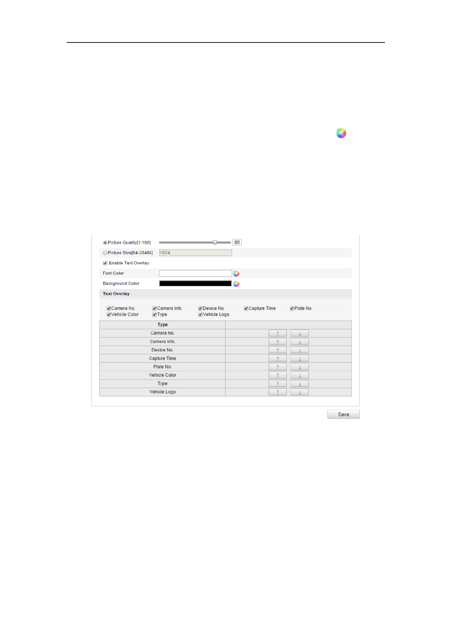
User Manual of Network Camera
142
Configuring the Upload Picture
1. Set the picture quality.
Either Picture Quality or Picture Size can be set to specify the picture quality.2.
2. (Optional) Enable and edit the text overlay on the upload picture.
You can set the font color and background color by clicking the icon , and click
the desired color in the pop-up palette.
3. Select the information for the text overlay, including camera No., camera info,
device No., capture time, plate No., vehicle color, etc. You can also click the up
and down direction buttons to adjust the sequence of the text.
4. Click the button to activate the settings. Save
Figure 9-2 Upload Picture Settings
Configuring the Overlay Content
1. Edit the content of the camera No., camera information and device information in
the corresponding text filed.
2. (Optional) Enable and edit the text overlay on the picture to upload.
3. Click the button to activate the settings. Save
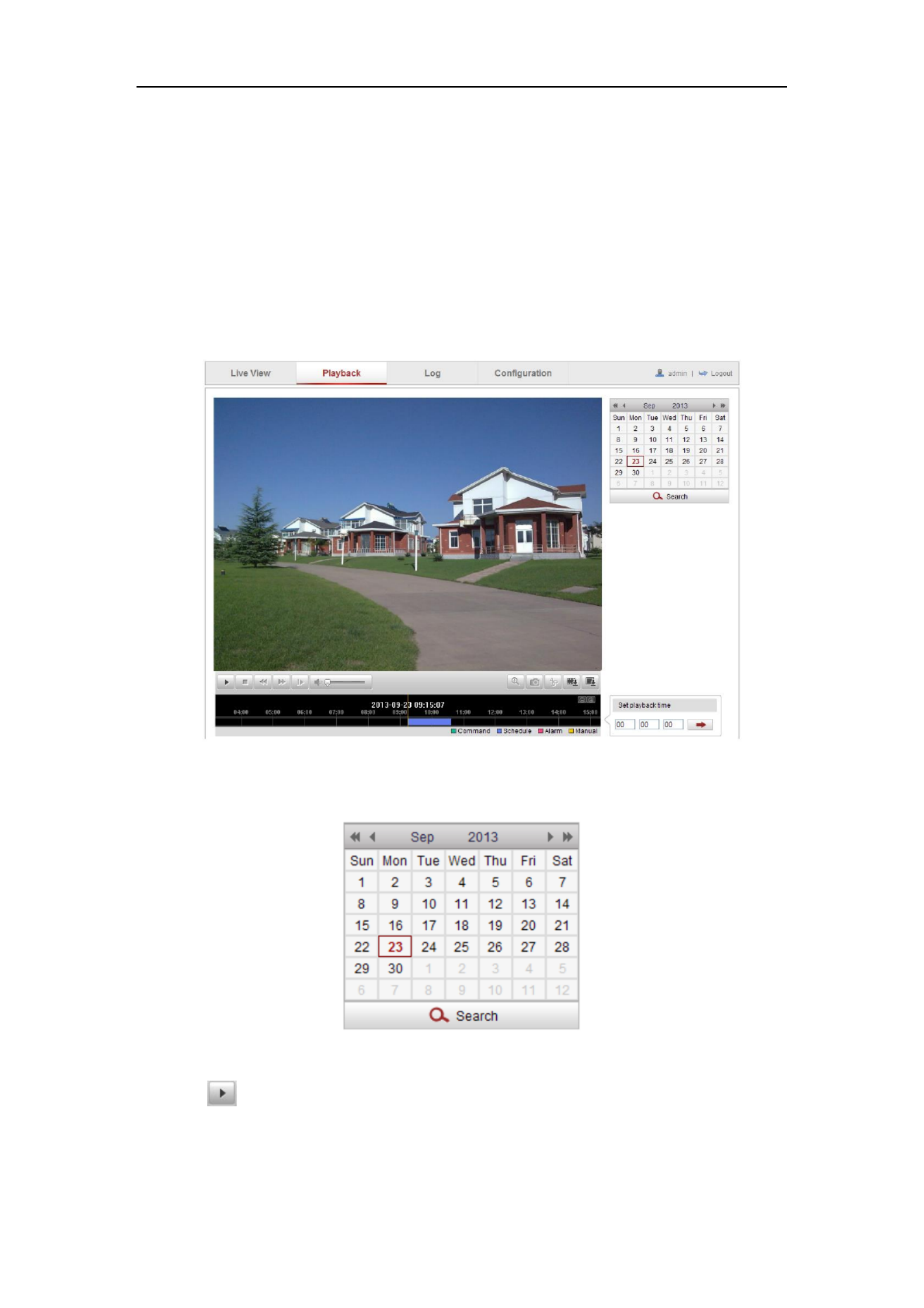
User Manual of Network Camera
144
Chapter 10 Playback
Purpose:
This section explains how to view the remotely recorded video files stored in the
network disks or SD cards.
Steps:
1. Click on the menu bar to enter playback interface. Playback
Figure 10-1 Playback Interface
2. Select the date and click Search.
Figure 10-2 Search Video
3. Click to play the video files found on this date.
The toolbar on the bottom of Playback interface can be used to control playing
process.

User Manual of Network Camera
145
Figure 10-3 Playback Toolbar
Table 10-1 Description of the buttons
Button
Operation
Button
Operation
Play
Capture a picture
Pause
/
Start/Stop clipping video
files
Stop
/
Audio on and adjust
volume/Mute
Speed down
Download video files
Speed up
Download captured
pictures
Playback by
frame
/
Enable/Disable digital
zoom
Note: You can choose the file paths locally for downloaded playback video files and
pictures in Local Configuration interface. Please refer to for details. Section 6.1
Drag the progress bar with the mouse to locate the exact playback point. You can also
input the time and click to locate the playback point in the Set playback time
field. You can also click to zoom out/in the progress bar.
Figure 10-4 Set Playback Time
Figure 10-5 Progress Bar
The different colors of the video on the progress bar stand for the different video
types.
Figure 10-6 Video Types
Product specificaties
| Merk: | Hikvision |
| Categorie: | Bewakingscamera |
| Model: | DS-2CD2132F-IWS-6MM |
| Kleur van het product: | Wit |
| Gewicht: | 500 g |
| Hoogte: | 82 mm |
| Soort: | IP-beveiligingscamera |
| Internationale veiligheidscode (IP): | IP66 |
| Wi-Fi-standaarden: | 802.11b, 802.11g, Wi-Fi 4 (802.11n) |
| Vormfactor: | Dome |
| Ondersteuning voor plaatsing: | Binnen & buiten |
| Connectiviteitstechnologie: | Bedraad en draadloos |
| Ethernet LAN: | Ja |
| Montagewijze: | Plafond/muur |
| Maximum resolutie: | 2048 x 1536 Pixels |
| Totaal aantal megapixels: | 3 MP |
| Videocompressieformaten: | H.264, M-JPEG |
| Diameter: | 111 mm |
| Stroomuitvoer (volt): | 12 |
| Minimale belichting: | 0 Lux |
| Field of view (FOV) hoek: | 43.3 ° |
| Aantal cameras: | 1 |
| Geïntegreerde geheugenkaartlezer: | Ja |
| Compatibele geheugenkaarten: | MicroSD (TransFlash), MicroSDHC, MicroSDXC |
| Ingebouwde HDD: | Nee |
| Nachtvisie: | Ja |
| Aantal Ethernet LAN (RJ-45)-poorten: | 1 |
| Vermogensverbruik (max): | 7 W |
| Omvang optische sensor: | 1/3 " |
| Type beeldsensor: | CMOS |
| Camera sluitertijd: | 1/3s ~ 1/100,100s s |
| Interface: | RJ-45 |
| Ruisonderdrukking: | Ja |
| Bekabelingstechnologie: | 10/100Base-T(X) |
| Ondersteunde beveiligingsalgoritmen: | 64-bit WEP, 128-bit WEP, WPA, WPA-PSK, WPA2, WPA2-PSK, WPS |
| Maximaal 30 frames per seconde: | 25 fps |
| Ondersteunde netwerkprotocollen: | TCP/IP, ICMP, HTTP, HTTPS, FTP, DHCP, DNS, DDNS, RTP, RTSP, RTCP, PPPoE, NTP, UPnP, SMTP, SNMP, IGMP, 802.1X, QoS, IPv6, Bonjour |
| Frequentiebereik: | 2.4 - 2.4835 Hz |
| Progressive scan: | Ja |
| Power over Ethernet (PoE): | Ja |
| PTZ control: | Ja |
| Maximale afstand: | 30 m |
| Draaihoek: | 360 ° |
| Pan bereik: | 0 - 355 ° |
| Dag/nacht modus: | Ja |
| Infrarood (IR)-afsluitingsfilter: | Ja |
| Aanpassing van de afbeeldingskwaliteit: | Brightness, Contrast, Saturation, Sharpness |
| Wide Dynamic Range (WDR): | Ja |
| Wifi: | Ja |
| Bedrijfstemperatuur (T-T): | -30 - 60 °C |
| Bereik kantelhoek: | 0 - 65 ° |
| Lens diameter: | 6 mm |
| Actieve ombevoegde demontage alarm: | Ja |
| Automatische versterking control: | Ja |
Heb je hulp nodig?
Als je hulp nodig hebt met Hikvision DS-2CD2132F-IWS-6MM stel dan hieronder een vraag en andere gebruikers zullen je antwoorden
Handleiding Bewakingscamera Hikvision

7 Februari 2025
7 Februari 2025
7 Februari 2025
7 Februari 2025
7 Februari 2025
7 Februari 2025
5 Februari 2025
5 Februari 2025
6 Januari 2025
18 December 2024
Handleiding Bewakingscamera
- Bewakingscamera Braun
- Bewakingscamera Bosch
- Bewakingscamera Philips
- Bewakingscamera Sony
- Bewakingscamera Samsung
- Bewakingscamera Xiaomi
- Bewakingscamera Panasonic
- Bewakingscamera Asus
- Bewakingscamera Canon
- Bewakingscamera Garmin
- Bewakingscamera Grundig
- Bewakingscamera Gigaset
- Bewakingscamera Honeywell
- Bewakingscamera JVC
- Bewakingscamera Motorola
- Bewakingscamera Pioneer
- Bewakingscamera Toshiba
- Bewakingscamera VTech
- Bewakingscamera Abus
- Bewakingscamera ACME
- Bewakingscamera Acti
- Bewakingscamera Ag Neovo
- Bewakingscamera Airlive
- Bewakingscamera Aldi
- Bewakingscamera Alecto
- Bewakingscamera Allnet
- Bewakingscamera Aluratek
- Bewakingscamera Anker
- Bewakingscamera Apc
- Bewakingscamera Aqara
- Bewakingscamera Aritech
- Bewakingscamera Avanti
- Bewakingscamera AVTech
- Bewakingscamera Axis
- Bewakingscamera Beafon
- Bewakingscamera Belkin
- Bewakingscamera Blaupunkt
- Bewakingscamera Boss
- Bewakingscamera Brinno
- Bewakingscamera BRK
- Bewakingscamera Buffalo
- Bewakingscamera Burg-Wachter
- Bewakingscamera D-Link
- Bewakingscamera Dedicated Micros
- Bewakingscamera Denver
- Bewakingscamera Digitus
- Bewakingscamera DIO
- Bewakingscamera Dorr
- Bewakingscamera E-bench
- Bewakingscamera Ebode
- Bewakingscamera Edimax
- Bewakingscamera Ednet
- Bewakingscamera Elmo
- Bewakingscamera Elro
- Bewakingscamera Eminent
- Bewakingscamera Engenius
- Bewakingscamera Eufy
- Bewakingscamera EverFocus
- Bewakingscamera Extech
- Bewakingscamera Ezviz
- Bewakingscamera Ferguson
- Bewakingscamera First Alert
- Bewakingscamera Flamingo
- Bewakingscamera Flir
- Bewakingscamera Foscam
- Bewakingscamera Friedland
- Bewakingscamera Ganz
- Bewakingscamera Gembird
- Bewakingscamera Genius
- Bewakingscamera GeoVision
- Bewakingscamera Gira
- Bewakingscamera Google
- Bewakingscamera Grandstream
- Bewakingscamera Hama
- Bewakingscamera Iget
- Bewakingscamera Iiquu
- Bewakingscamera Iluv
- Bewakingscamera Indexa
- Bewakingscamera InFocus
- Bewakingscamera Interlogix
- Bewakingscamera Ion
- Bewakingscamera Kerbl
- Bewakingscamera KlikaanKlikuit
- Bewakingscamera Kodak
- Bewakingscamera Kogan
- Bewakingscamera Konig
- Bewakingscamera Laserliner
- Bewakingscamera LevelOne
- Bewakingscamera Linksys
- Bewakingscamera Logilink
- Bewakingscamera Logitech
- Bewakingscamera Lorex
- Bewakingscamera Maginon
- Bewakingscamera Manhattan
- Bewakingscamera Marmitek
- Bewakingscamera Marquant
- Bewakingscamera Marshall
- Bewakingscamera Megasat
- Bewakingscamera Minox
- Bewakingscamera Mitsubishi
- Bewakingscamera Monacor
- Bewakingscamera Nedis
- Bewakingscamera Nest
- Bewakingscamera Netatmo
- Bewakingscamera Netgear
- Bewakingscamera Netis
- Bewakingscamera Notifier
- Bewakingscamera Perel
- Bewakingscamera Powerfix
- Bewakingscamera Profile
- Bewakingscamera Provision ISR
- Bewakingscamera Pyle
- Bewakingscamera Quantum
- Bewakingscamera Raymarine
- Bewakingscamera Renkforce
- Bewakingscamera Revo
- Bewakingscamera Ricoh
- Bewakingscamera Ring
- Bewakingscamera Rollei
- Bewakingscamera Sanyo
- Bewakingscamera Satel
- Bewakingscamera Schneider
- Bewakingscamera SecurityMan
- Bewakingscamera Siedle
- Bewakingscamera Sitecom
- Bewakingscamera Smartwares
- Bewakingscamera SMC
- Bewakingscamera Somfy
- Bewakingscamera Sonic Alert
- Bewakingscamera Stabo
- Bewakingscamera Strong
- Bewakingscamera Switel
- Bewakingscamera Synology
- Bewakingscamera Technaxx
- Bewakingscamera Tenda
- Bewakingscamera Thomson
- Bewakingscamera TP Link
- Bewakingscamera Trebs
- Bewakingscamera Trendnet
- Bewakingscamera Trust
- Bewakingscamera Uniden
- Bewakingscamera V-Tac
- Bewakingscamera Velleman
- Bewakingscamera Vitek
- Bewakingscamera Vivotek
- Bewakingscamera Waeco
- Bewakingscamera Western Digital
- Bewakingscamera Withings
- Bewakingscamera Woonveilig
- Bewakingscamera Xavax
- Bewakingscamera Y-cam
- Bewakingscamera Yale
- Bewakingscamera Zebra
- Bewakingscamera ZTE
- Bewakingscamera ZyXEL
- Bewakingscamera Jung
- Bewakingscamera Olympia
- Bewakingscamera Oplink
- Bewakingscamera Orion
- Bewakingscamera Overmax
- Bewakingscamera Clas Ohlson
- Bewakingscamera Caliber
- Bewakingscamera Exibel
- Bewakingscamera Monoprice
- Bewakingscamera Naxa
- Bewakingscamera Niceboy
- Bewakingscamera Schwaiger
- Bewakingscamera Steren
- Bewakingscamera Ubiquiti Networks
- Bewakingscamera EMOS
- Bewakingscamera Conceptronic
- Bewakingscamera Miniland
- Bewakingscamera Arlo
- Bewakingscamera Atlona
- Bewakingscamera Avidsen
- Bewakingscamera Hamlet
- Bewakingscamera Hive
- Bewakingscamera Imou
- Bewakingscamera INSTAR
- Bewakingscamera SereneLife
- Bewakingscamera Defender
- Bewakingscamera Trevi
- Bewakingscamera Adesso
- Bewakingscamera Broan
- Bewakingscamera DSC
- Bewakingscamera M-e
- Bewakingscamera Blow
- Bewakingscamera Genie
- Bewakingscamera ClearOne
- Bewakingscamera Chacon
- Bewakingscamera Swann
- Bewakingscamera Approx
- Bewakingscamera SPC
- Bewakingscamera Canyon
- Bewakingscamera Cisco
- Bewakingscamera EVOLVEO
- Bewakingscamera Whistler
- Bewakingscamera Delta Dore
- Bewakingscamera Furrion
- Bewakingscamera Comtrend
- Bewakingscamera Planet
- Bewakingscamera Blink
- Bewakingscamera Intellinet
- Bewakingscamera Aida
- Bewakingscamera Lindy
- Bewakingscamera AVerMedia
- Bewakingscamera Lumens
- Bewakingscamera Mobi
- Bewakingscamera Fortinet
- Bewakingscamera DataVideo
- Bewakingscamera Hombli
- Bewakingscamera Vaddio
- Bewakingscamera Adj
- Bewakingscamera Ikan
- Bewakingscamera Dahua Technology
- Bewakingscamera UniView
- Bewakingscamera Reolink
- Bewakingscamera Valueline
- Bewakingscamera EVE
- Bewakingscamera QSC
- Bewakingscamera Marshall Electronics
- Bewakingscamera Boyo
- Bewakingscamera IC Intracom
- Bewakingscamera CRUX
- Bewakingscamera POSline
- Bewakingscamera August
- Bewakingscamera Hawking Technologies
- Bewakingscamera Lanberg
- Bewakingscamera Nexxt
- Bewakingscamera Watec
- Bewakingscamera Equip
- Bewakingscamera Crestron
- Bewakingscamera Chuango
- Bewakingscamera ORNO
- Bewakingscamera ETiger
- Bewakingscamera Videcon
- Bewakingscamera Advantech
- Bewakingscamera Moxa
- Bewakingscamera Digital Watchdog
- Bewakingscamera Brilliant
- Bewakingscamera Moen
- Bewakingscamera Kramer
- Bewakingscamera MEE Audio
- Bewakingscamera Brickcom
- Bewakingscamera Kwikset
- Bewakingscamera Linear PRO Access
- Bewakingscamera BirdDog
- Bewakingscamera AVer
- Bewakingscamera Summer Infant
- Bewakingscamera Topica
- Bewakingscamera Vimar
- Bewakingscamera Speco Technologies
- Bewakingscamera Verint
- Bewakingscamera ZKTeco
- Bewakingscamera Rostra
- Bewakingscamera Kguard
- Bewakingscamera Caddx
- Bewakingscamera Spyclops
- Bewakingscamera EKO
- Bewakingscamera Inovonics
- Bewakingscamera Surveon
- Bewakingscamera Hollyland
- Bewakingscamera Epcom
- Bewakingscamera AViPAS
- Bewakingscamera Lutec
- Bewakingscamera Hanwha
- Bewakingscamera ClearView
- Bewakingscamera VideoComm
- Bewakingscamera IMILAB
- Bewakingscamera InfiRay
- Bewakingscamera 3xLOGIC
- Bewakingscamera Pelco
- Bewakingscamera Leviton
- Bewakingscamera EtiamPro
- Bewakingscamera Inkovideo
- Bewakingscamera Pentatech
- Bewakingscamera Weldex
- Bewakingscamera CNB Technology
- Bewakingscamera Tapo
- Bewakingscamera Aigis
- Bewakingscamera Exacq
- Bewakingscamera Laxihub
- Bewakingscamera Securetech
- Bewakingscamera EFB Elektronik
- Bewakingscamera Ernitec
- Bewakingscamera NetMedia
- Bewakingscamera Videotec
- Bewakingscamera Illustra
- Bewakingscamera AVMATRIX
- Bewakingscamera Nivian
- Bewakingscamera Arenti
- Bewakingscamera Syscom
- Bewakingscamera Tecno
- Bewakingscamera Night Owl
- Bewakingscamera Guardzilla
- Bewakingscamera Astak
- Bewakingscamera Milestone Systems
- Bewakingscamera Zavio
- Bewakingscamera Campark
- Bewakingscamera IPX
- Bewakingscamera Promise Technology
- Bewakingscamera Annke
- Bewakingscamera Qoltec
- Bewakingscamera Digimerge
- Bewakingscamera Alfatron
- Bewakingscamera Feelworld
- Bewakingscamera KJB Security Products
- Bewakingscamera British Telecom
- Bewakingscamera Wisenet
- Bewakingscamera Ecobee
- Bewakingscamera BZBGear
- Bewakingscamera WyreStorm
- Bewakingscamera Infortrend
- Bewakingscamera Epiphan
- Bewakingscamera HiLook
- Bewakingscamera Mach Power
- Bewakingscamera Compro
- Bewakingscamera Ikegami
- Bewakingscamera Accsoon
- Bewakingscamera Vimtag
- Bewakingscamera Sonoff
- Bewakingscamera Gewiss
- Bewakingscamera Alula
- Bewakingscamera Insteon
- Bewakingscamera Costar
- Bewakingscamera ALC
- Bewakingscamera Security Labs
- Bewakingscamera American Dynamics
- Bewakingscamera Seneca
- Bewakingscamera Avigilon
- Bewakingscamera Vosker
- Bewakingscamera Sentry360
- Bewakingscamera Bea-fon
- Bewakingscamera Owltron
- Bewakingscamera Petcube
- Bewakingscamera Enabot
- Bewakingscamera Luis Energy
- Bewakingscamera Sir Gawain
- Bewakingscamera VisorTech
- Bewakingscamera Atlantis Land
- Bewakingscamera B & S Technology
- Bewakingscamera I3International
- Bewakingscamera IDIS
- Bewakingscamera Turing
- Bewakingscamera Qian
- Bewakingscamera Wasserstein
- Bewakingscamera Qolsys
- Bewakingscamera Control4
- Bewakingscamera Milesight
- Bewakingscamera GVI Security
- Bewakingscamera Conbrov
- Bewakingscamera HuddleCamHD
- Bewakingscamera Setti+
- Bewakingscamera Mobotix
- Bewakingscamera IOIO
- Bewakingscamera BIRDFY
- Bewakingscamera I-PRO
- Bewakingscamera DVDO
- Bewakingscamera TCP
- Bewakingscamera Bolin Technology
- Bewakingscamera Konyks
- Bewakingscamera Nextech
- Bewakingscamera Arecont Vision
- Bewakingscamera YoloLiv
Nieuwste handleidingen voor Bewakingscamera

30 Maart 2025
29 Maart 2025
29 Maart 2025
29 Maart 2025
29 Maart 2025
29 Maart 2025
27 Maart 2025
27 Maart 2025
27 Maart 2025
26 Maart 2025