Dell Vostro 200 Handleiding
Lees hieronder de 📖 handleiding in het Nederlandse voor Dell Vostro 200 (210 pagina's) in de categorie Desktop. Deze handleiding was nuttig voor 46 personen en werd door 2 gebruikers gemiddeld met 4.5 sterren beoordeeld
Pagina 1/210

w w w. d e l l . c o m | s u p p o r t . d e l l . c o m
Dell™ Vostro™ 200
Owner’s Manual – Slim Tower
Model DCSLF

Notes, Notices, and Cautions
NOTE: A NOTE indicates important information that helps you make better use of
your computer.
NOTICE: A NOTICE indicates either potential damage to hardware or loss of data
and tells you how to avoid the problem.
CAUTION: A CAUTION indicates a potential for property damage, personal injury,
or death.
If you purchased a Dell™ n Series computer, any references in this document to
Microsoft
®
Windows
®
operating systems are not applicable.
Abbreviations and Acronyms
For a complete list of abbreviations and acronyms, see the "Glossary" on
page 185.
____________________
Information in this document is subject to change without notice.
© 2007 Dell Inc. All rights reserved.
Reproduction in any manner whatsoever without the written permission of Dell Inc. is strictly forbidden.
Trademarks used in this text: Dell, the DELL logo, Vostro, TravelLite, and Strike Zone are trademarks
of Dell Inc.; Bluetooth is a registered trademark owned by Bluetooth SIG, Inc. and is used by Dell
under license; Microsoft, Windows, Outlook, and Windows Vista are either trademarks or registered
trademarks of Microsoft Corporation in the United States and/or other countries. Intel, Pentium, and
Celeron are registered trademarks, SpeedStep and Core are trademarks of Intel Corporation.
Other trademarks and trade names may be used in this document to refer to either the entities claiming
the marks and names or their products. Dell Inc. disclaims any proprietary interest in trademarks and
trade names other than its own.
Model DCSLF
July 2007 P/N PK009 Rev. A01

Contents 3
Contents
1 Finding Information . . . . . . . . . . . . . . . . . 11
2 Setting Up and Using Your Computer . . . 15
Front View of the Computer . . . . . . . . . . . . . . . 15
Back View of the Computer . . . . . . . . . . . . . . . 17
Back Panel Connectors . . . . . . . . . . . . . . 18
Installing Your Computer in an Enclosure . . . . . . . 20
Setting Up a Printer . . . . . . . . . . . . . . . . . . . 22
Printer Cable . . . . . . . . . . . . . . . . . . . . 23
Connecting a USB Printer . . . . . . . . . . . . . 23
Playing CDs and DVDs . . . . . . . . . . . . . . . . . 24
Adjusting the Volume . . . . . . . . . . . . . . . . 26
Adjusting the Picture . . . . . . . . . . . . . . . . 26
Copying CDs and DVDs . . . . . . . . . . . . . . . . . 27
Using a Media Card Reader (Optional) . . . . . . . . . 30
Connecting Two Monitors . . . . . . . . . . . . . . . . 31
Connecting Two Monitors With VGA
Connectors . . . . . . . . . . . . . . . . . . . . . 31
Connecting One Monitor With a VGA Connector
and One Monitor With a DVI Connector . . . . . . 32
Connecting a TV . . . . . . . . . . . . . . . . . . 32
Changing the Display Settings . . . . . . . . . . . 33

4Contents
Power Management Options in Windows XP . . . . . 33
Standby Mode . . . . . . . . . . . . . . . . . . . 33
Hibernate Mode . . . . . . . . . . . . . . . . . . 34
Power Options Properties . . . . . . . . . . . . . 35
Power Management Options in Windows Vista . . . . 36
Standby Mode . . . . . . . . . . . . . . . . . . . 37
Hibernate Mode . . . . . . . . . . . . . . . . . . 38
Power Plan Properties . . . . . . . . . . . . . . . 38
Enabling SpeedStep™ Technology . . . . . . . . . . . 40
About RAID Configurations . . . . . . . . . . . . . . . 40
RAID Level 1 Configuration . . . . . . . . . . . . . 40
Configuring Your Hard Drives for RAID . . . . . . . 41
Configuring for RAID Using the Intel® Option
ROM Utility . . . . . . . . . . . . . . . . . . . . . 42
Configuring for RAID Using the Intel® Matrix
Storage Manager . . . . . . . . . . . . . . . . . . 43
Transferring Information to a New Computer. . . . . . 47
Setting Up a Home and Office Network . . . . . . . . . 51
Connecting to a Network Adapter . . . . . . . . . 51
Network Setup Wizard . . . . . . . . . . . . . . . 52
Connecting to the Internet . . . . . . . . . . . . . . . . 53
Setting Up Your Internet Connection . . . . . . . . 54
3 Solving Problems . . . . . . . . . . . . . . . . . . . 57
Troubleshooting Tips . . . . . . . . . . . . . . . . . . 57
Battery Problems . . . . . . . . . . . . . . . . . . . . 57

Contents 5
Drive Problems . . . . . . . . . . . . . . . . . . . . . 58
Optical drive problems . . . . . . . . . . . . . . . 59
Hard drive problems . . . . . . . . . . . . . . . . 60
E-Mail, Modem, and Internet Problems . . . . . . . . 60
Error Messages . . . . . . . . . . . . . . . . . . . . . 63
Keyboard Problems . . . . . . . . . . . . . . . . . . . 64
Lockups and Software Problems . . . . . . . . . . . . 65
The computer does not start up . . . . . . . . . . 65
The computer stops responding . . . . . . . . . . 65
A program stops responding . . . . . . . . . . . . 65
A program crashes repeatedly . . . . . . . . . . 65
A program is designed for an earlier Microsoft®
Windows® operating system . . . . . . . . . . . 66
A solid blue screen appears . . . . . . . . . . . . 66
Other software problems . . . . . . . . . . . . . 67
Media Card Reader Problems . . . . . . . . . . . . . . 68
Memory Problems . . . . . . . . . . . . . . . . . . . . 69
Mouse Problems . . . . . . . . . . . . . . . . . . . . 70
Network Problems . . . . . . . . . . . . . . . . . . . 71
Power Problems . . . . . . . . . . . . . . . . . . . . . 72
Printer Problems . . . . . . . . . . . . . . . . . . . . 73
Scanner Problems . . . . . . . . . . . . . . . . . . . . 74
Sound and Speaker Problems . . . . . . . . . . . . . 75
No sound from speakers . . . . . . . . . . . . . . 75
No sound from headphones . . . . . . . . . . . . 76

6Contents
Video and Monitor Problems . . . . . . . . . . . . . . 77
If the screen is blank . . . . . . . . . . . . . . . . 77
If the screen is difficult to read. . . . . . . . . . . 78
4 Troubleshooting Tools . . . . . . . . . . . . . . . 79
Power Lights . . . . . . . . . . . . . . . . . . . . . . . 79
Beep Codes . . . . . . . . . . . . . . . . . . . . . . . 80
System Messages . . . . . . . . . . . . . . . . . . . . 82
Dell Diagnostics . . . . . . . . . . . . . . . . . . . . . 84
When to Use the Dell Diagnostics . . . . . . . . . 84
Starting the Dell Diagnostics From Your
Hard Drive . . . . . . . . . . . . . . . . . . . . . 84
Starting the Dell Diagnostics From the Drivers
and Utilities Media . . . . . . . . . . . . . . . . . 85
Dell Diagnostics Main Menu . . . . . . . . . . . . 85
Drivers . . . . . . . . . . . . . . . . . . . . . . . . . . 87
What Is a Driver? . . . . . . . . . . . . . . . . . . 87
Identifying Drivers . . . . . . . . . . . . . . . . . 88
Reinstalling Drivers and Utilities . . . . . . . . . . 88
Restoring Your Operating System . . . . . . . . . . . . 91
Using Microsoft Windows System Restore . . . . 92
Using Dell PC Restore and Dell Factory
Image Restore . . . . . . . . . . . . . . . . . . . 93
Using the Operating System Media . . . . . . . . 96
Troubleshooting Software and Hardware
Problems . . . . . . . . . . . . . . . . . . . . . . 97

Contents 7
5 Removing and Installing Parts . . . . . . . . 99
Before You Begin . . . . . . . . . . . . . . . . . . . . 99
Recommended Tools . . . . . . . . . . . . . . . . 99
Turning Off Your Computer . . . . . . . . . . . . . 100
Before Working Inside Your Computer . . . . . . . 100
Removing the Computer Cover . . . . . . . . . . . . . 101
Removing the Support Bracket . . . . . . . . . . . . . 102
Inside View of Your Computer . . . . . . . . . . . . . 104
System Board Components . . . . . . . . . . . . . . . 105
Power Supply DC Connector Pin Assignments . . . . . 107
Memory . . . . . . . . . . . . . . . . . . . . . . . . . 111
Memory Installation Guidelines . . . . . . . . . . 111
Installing Memory . . . . . . . . . . . . . . . . . 112
Removing Memory . . . . . . . . . . . . . . . . . 114
Cards . . . . . . . . . . . . . . . . . . . . . . . . . . . 115
PCI and PCI Express Cards . . . . . . . . . . . . . 115
Bezel . . . . . . . . . . . . . . . . . . . . . . . . . . . 121
Removing the Bezel . . . . . . . . . . . . . . . . 122
Replacing the Bezel . . . . . . . . . . . . . . . . 123
Drives . . . . . . . . . . . . . . . . . . . . . . . . . . 124
Recommended Drive Cable Connections . . . . . 124
Connecting Drive Cables . . . . . . . . . . . . . . 125
Drive Interface Connectors . . . . . . . . . . . . 125
Connecting and Disconnecting Drive Cables . . . 126
Hard Drives . . . . . . . . . . . . . . . . . . . . . 126

10 Contents
Glossary . . . . . . . . . . . . . . . . . . . . . . . . . . . 185
Index . . . . . . . . . . . . . . . . . . . . . . . . . . . . . . 203
12 Finding Information
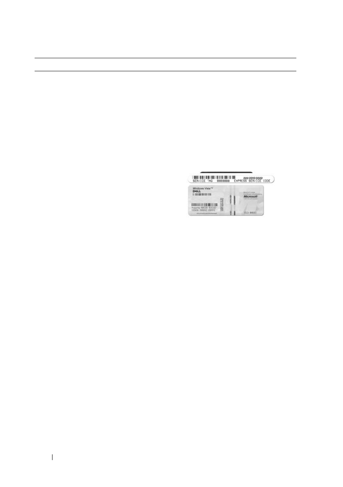
• Service Tag and Express Service Code
• Microsoft Windows License Label
Service Tag and Microsoft
®
Windows
®
License
These labels are located on your
computer.
• Use the Service Tag to identify your
computer when you use
support.dell.com
or contact support.
• Enter the Express Service Code to
direct your call when contacting
support.
NOTE: As an increased security measure,
the newly designed Microsoft Windows
license label incorporates a missing portion
or "hole" to discourage removal of the label.
What Are You Looking For? Find it Here

Finding Information 13
• Solutions — Troubleshooting hints and
tips, articles from technicians, and
online courses, frequently asked
questions
• Community — Online discussion with
other Dell customers
• Upgrades — Upgrade information for
components, such as memory, the hard
drive, and the operating system
• Customer Care — Contact information,
service call and order status, warranty,
and repair information
• Service and support — Service call
status and support history, service
contract, online discussions with
technical support
• Reference — Computer
documentation, details on my computer
configuration, product specifications,
and white papers
• Downloads — Certified drivers,
patches, and software updates
Dell Support Website — support.dell.com
NOTE: Select your region to view the
appropriate support site.
NOTE: Corporate, government, and
education customers can also use the
customized Dell Premier Support website
at premier.support.dell.com.
• Desktop System Software (DSS)— If
you reinstall the operating system for
your computer, you should also reinstall
the DSS utility. DSS provides critical
updates for your operating system and
support for Dell™ 3.5-inch USB floppy
drives, optical drives, and USB devices.
DSS is necessary for correct operation of
your Dell computer. The software
automatically detects your computer
and operating system and installs the
updates appropriate for your
configuration.
To download
Desktop
System Software:
1
Go to
support.dell.com
and click
Downloads
.
2
Enter your Service Tag or product
model.
3
In the
Download Category
drop-down
menu, click
All
.
4
Select the operating system and
operating system language for your
computer, and click
Submit.
5
Under
Select a Device
, scroll to
System
and Configuration Utilities
, and click
Dell Desktop System Software
.
What Are You Looking For? Find it Here

14 Finding Information
• How to use Windows Vista™
• How to work with programs and files
• How to personalize my desktop
Windows Help and Support Center
1
To access Windows Help and Support:
• In Windows XP, click
Start
and click
Help and Support
.
• In Windows Vista™, click the
Windows Vista Start button
and
click
Help and Support
.
2
Type a word or phrase that describes
your problem, and then click the arrow
icon.
3
Click the topic that describes your
problem.
4
Follow the instructions on the screen.
What Are You Looking For? Find it Here

Setting Up and Using Your Computer 15
Setting Up and Using Your Computer
Front View of the Computer
1
2
6
8
10
4
9
11
3
5
7

16 Setting Up and Using Your Computer
1location of Service Tag Use the Service Tag to identify your computer
when you access the Dell Support website or call
technical support.
2eject button for optical
drive
Press here to open or close the optical drive.
3FlexBay open/close Press here to open or close the floppy/media card
reader panel
4optical drive Can contain an optional optical drive.
5FlexBay drive Can contain an optional floppy drive or optional
Media Card Reader. For information on using the
Media Card Reader, see "Media Card Reader" on
page 136.
6power button Press the power button to turn on the computer.
NOTICE: To avoid losing data, do not use the
power button to turn off the computer. Instead,
perform an operating system shutdown.
7power light The light in the center of this button indicates
power state.
8USB 2.0 connectors (2) Use the front USB connectors for devices that you
connect occasionally, such as joysticks or cameras,
or for bootable USB devices (see "System Setup
Options" on page 172 for more information on
booting to a USB device).
It is recommended that you use the back USB
connectors for devices that typically remain
connected, such as printers and keyboards.
9microphone connector Use the microphone connector to attach a personal
computer microphone for voice or musical input
into a sound or telephony program.
On computers with a sound card, the microphone
connector is on the card.
10 headphone connector Use the headphone connector to attach
headphones and most kinds of speakers.
11 drive activity light The drive activity light is on when the computer
reads data from or writes data to the hard drive.
The light might also be on when a device such as a
CD player is operating.

Setting Up and Using Your Computer 17
Back View of the Computer
1back panel connectors Plug USB, audio, and other devices into the
appropriate connector. See "Back Panel Connectors"
on page 18 for more information.
2card slots Access connectors for any installed PCI and PCI
Express cards.
3power supply LED Indicates power availability for power supply.
2
3
5
4
1

18 Setting Up and Using Your Computer
Back Panel Connectors
4power connector Insert the power cable.
5padlock rings Padlock rings are for attaching a commercially
available theft-deterrent device. The padlock rings
allows you to secure the computer cover to the chassis
with a padlock to prevent unauthorized access to the
inside of the computer. To use the padlock rings,
insert a commercially available padlock through the
rings, and then lock the padlock.
1network activity
light
Flashes a yellow light when the computer is transmitting or
receiving network data. A high volume of network traffic
may make this light appear to be in a steady "on" state.
1 2
8
7
3 4
5
6
10
11 9

Setting Up and Using Your Computer 19
2network adapter
connector
To attach your computer to a network or broadband device,
connect one end of a network cable to either a network port
or your network or broadband device. Connect the other
end of the network cable to the network adapter connector
on the back panel of your computer. A click indicates that
the network cable has been securely attached.
NOTE: Do not plug a telephone cable into the network
connector.
On computers with a network connector card, use the
connector on the card.
It is recommended that you use Category 5 wiring and
connectors for your network. If you must use Category 3
wiring, force the network speed to 10 Mbps to ensure
reliable operation.
3link integrity light
• Green — A good connection exists between a
10/100-Mbps network and the computer.
• Off — The computer is not detecting a physical
connection to the network.
4center/subwoofer
connector
Use the orange connector to attach a speaker to a Low
Frequency Effects (LFE) audio channel. LFE audio
channel is found in digital surround sound audio schemes
that carries only low frequency information of 80 Hz and
below. The LFE channel drives a subwoofer to provide
extremely low bass extension. Systems not using
subwoofers can shunt the LFE information to the main
speakers in the surround sound set-up.
5line-in connector Use the blue line-in connector to attach a record/playback
device such as a cassette player, CD player, or VCR.
On computers with a sound card, use the connector on the
card.
6front L/R line-out
connector
Use the green line-out connector (available on computers
with integrated sound) to attach headphones and most
speakers with integrated amplifiers.
On computers with a sound card, use the connector on the
card.

20 Setting Up and Using Your Computer
Installing Your Computer in an Enclosure
Installing your computer in an enclosure can restrict the airflow and impact
your computer’s performance, possibly causing it to overheat. Follow the
guidelines below when installing your computer in an enclosure:
NOTICE: The operating temperature specifications in your Owner’s Manual reflect
the maximum ambient operating temperature. The room ambient temperature
needs to be a consideration when installing your computer in an enclosure. For
example, if the ambient room temperature is at 25° C (77° F), depending on your
computer’s specifications, you only have 5° to 10° C (9° to 18° F) temperature margin
before you reach your computer’s maximum operating temperature. For details
about your computer’s specifications, see "Specifications" on page 165.
• Leave a 10.2 cm (4 in) minimum clearance on all vented sides of the
computer to permit the airflow required for proper ventilation.
• If your enclosure has doors, the doors need to be of a type that allows at
least 30% airflow through the enclosure (front and back).
7microphone
connector
Use the pink connector to attach a personal computer
microphone for voice or musical input into a sound or
telephony program.
On computers with a sound card, the microphone
connector is on the card.
8side L/R surround
connector
Use the gray connector to provide enhanced surround
audio for computers with 7.1 speakers.
On computers with a sound card, the microphone
connector is on the card.
9rear L/R surround
connector
Use the black surround connector to attach multichannel-
capable speakers.
10 USB 2.0
connectors (4)
Use the back USB connectors for devices that typically
remain connected, such as printers and keyboards.
It is recommended that you use the front USB connectors
for devices that you connect occasionally, such as joysticks
or cameras.
11 VGA video
connector
Connect the monitor’s VGA cable to the VGA connector
on the computer.
On computers with a video card, use the connector on the
card.

Setting Up and Using Your Computer 21
• If your computer is installed in a corner on a desk or under a desk, leave at
least 5.1 cm (2 in) clearance from the back of the computer to the wall to
permit the airflow required for proper ventilation.

22 Setting Up and Using Your Computer
• Do not install your computer in an enclosure that does not allow airflow.
Restricting the airflow impacts your computer’s performance, possibly
causing it to overheat.
Setting Up a Printer
NOTICE: Complete the operating system setup before you connect a printer to the
computer.
See the documentation that came with the printer for setup information,
including how to:
• Obtain and install updated drivers.
• Connect the printer to the computer.
• Load paper and install the toner or ink cartridge.
For technical assistance, refer to the printer owner's manual or contact the
printer manufacturer.

Setting Up and Using Your Computer 23
Printer Cable
Your printer connects to your computer with either a USB cable or a parallel
cable. Your printer may not come with a printer cable, so if you purchase a
cable separately, ensure that it is compatible with your printer and computer.
If you purchased a printer cable at the same time you purchased your
computer, the cable may arrive in the computer’s shipping box.
Connecting a USB Printer
NOTE: You can connect USB devices while the computer is turned on.
1
Complete the operating system setup if you have not already done so.
2
Attach the USB printer cable to the USB connectors on the computer and
the printer. The USB connectors fit only one way.
1 USB connector on
computer
2 USB connector on
printer
3 USB printer cable
2
1
3

24 Setting Up and Using Your Computer
3
Turn on the printer and then turn on the computer.
4
Depending on your computer’s operating system, a printer wizard may be
available to help you install the printer driver:
In Windows
®
XP
,
click
Start
→
Printers and Faxes
→
Add a printer
to start
the Add Printer Wizard.
In Windows Vista™, click
Start
→
Network
→
Add a printer
to start
the Add Printer Wizard.
5
Install the printer driver if necessary. See "Reinstalling Drivers and
Utilities" on page 88 and the documentation that came with your printer.
Playing CDs and DVDs
NOTICE: Do not press down on the CD or DVD tray when you open or close it. Keep
the tray closed when you are not using the drive.
NOTICE: Do not move the computer when you are playing CDs or DVDs.
1
Press the eject button on the front of the drive.
2
Place the disc, label side out, in the center of the tray. Secure the edges of
the disc under the tabs along the edge of the tray.
3
Gently push in the tray.
NOTE: If you use a module that shipped with another computer, you need to install
the drivers and software necessary to play DVDs or write data. For more
information, see the Drivers and Utilities CD.

Setting Up and Using Your Computer 25
To format CDs for storing data, to create music CDs, or to copy CDs, see the
CD software that came with your computer.
NOTE: Ensure that you follow all copyright laws when you create CDs.
A CD player includes the following basic buttons:
A DVD player includes the following basic buttons:
For more information on playing CDs or DVDs, click Help on the CD or
DVD player (if available).
Play
Move backward within the current track
Pause
Move forward within the current track
Stop
Go to the previous track
Eject
Go to the next track
Stop
Restart the current chapter
Play
Fast forward
Pause
Fast reverse
Advance a single frame while in pause mode
Go to the next title or chapter
Continuously play the current title or chapter
Go to the previous title or chapter
Eject

26 Setting Up and Using Your Computer
Adjusting the Volume
NOTE: When the speakers are muted, you do not hear the CD or DVD playing.
1
Open the
Volume Control
window.
2
Click and drag the bar in the
Volume Control
column and slide it up or
down to increase or decrease the volume.
For more information on volume control options, click Help in the Volume
Control window.
Adjusting the Picture
If an error message notifies you that the current resolution and color depth
are using too much memory and preventing DVD playback, adjust the display
properties:
Windows XP
1
Click
Start
→
Control Panel
→
Appearance and Themes
.
2
Under
Pick a task...
, click
Change the screen resolution
.
3
Under
Screen resolution
, click and drag the bar to reduce the resolution
setting.
4
In the drop-down menu under
Color quality
, click
Medium (16 bit)
and
click
OK
.
Windows Vista
1
Click Start
→
Control Panel
→
Appearance and Personalization
.
2
Under
Personalization
, click
Adjust Screen Resolution
.
The
Display Properties
window appears.
3
Under
Resolution:
click and drag the bar reduce the resolution setting.
4
In the drop-down menu under
Colors:
, click
Medium (16 bit)
.
5
Click
OK
.

Setting Up and Using Your Computer 27
Copying CDs and DVDs
NOTE: Ensure that you observe all copyright laws when creating CDs or DVDs.
This section applies only to computers that have a CD-RW, DVD+/-RW, or
CD-RW/DVD (combo) drive.
NOTE: The types of CD or DVD drives offered by Dell may vary by country.
The following instructions explain how to make an exact copy of a CD or
DVD using Roxio Creator Plus - Dell Edition. You can also use Roxio Creator
Plus for other purposes, such as creating music CDs from audio files stored on
your computer or backing up important data. For help, open Roxio Creator
Plus, and then click the question mark icon in the upper-right corner of the
window.
How to Copy a CD or DVD
NOTE: CD-RW/DVD combo drives cannot write to DVD media. If you have a
CD-RW/DVD combo drive and you experience recording problems, check for
available software patches on the Sonic support website at sonic.com.
The DVD-writable drives installed in Dell™ computers can write to and read
DVD+/-R, DVD+/-RW and DVD+R DL (dual layer) media, but cannot
write to and may not read DVD-RAM or DVD-R DL media.
NOTE: Most commercial DVDs have copyright protection and cannot be copied
using Roxio Creator Plus.
1
Open Roxio Creator Plus.
2
Under the
Copy
tab, click
Disc Copy
.
3
To copy the CD or DVD:
•
If you have one CD/DVD drive
, ensure that the settings are correct, and
then click
Disc Copy
. The computer reads your source CD or DVD
and copies the data to a temporary folder on your computer hard
drive.
When prompted, insert a blank CD or DVD into the drive and
click
OK
.

28 Setting Up and Using Your Computer
•
If you have two CD/DVD drives
, select the drive into which you have
inserted your source CD or DVD, and then click
Disc
Copy
. The
computer copies the data from the source CD or DVD to the blank
CD or DVD.
Once you have finished copying the source CD or DVD, the CD or DVD
that you have created automatically ejects.
Using Blank CDs and DVDs
CD-RW drives can write to CD recording media only (including high-speed
CD-RW media), while DVD-writable drives can write to both CD and DVD
recording media.
Use blank CD-Rs to record music or permanently store data files. After the
maximum storage capacity of a CD-R is reached, you cannot write to that
CD-R again (see the Sonic documentation for more information). Use blank
CD-RWs if you plan to erase, rewrite, or update information on the CD later.
Blank DVD+/-Rs can be used to permanently store large amounts of data.
After you create a DVD+/-R disc, you may not be able to write to that disc
again if the disc is finalized or closed during the final stage of the disc creation
process. Use blank DVD+/-RWs if you plan to erase, rewrite, or update
information on the disc later.
CD-Writable Drives
DVD-Writable Drives
Media Type Read Write Rewritable
CD-R Yes Yes No
CD-RW Yes Yes Yes
Media Type Read Write Rewritable
CD-R Yes Yes No
CD-RW Yes Yes Yes
DVD+R Yes Yes No
DVD-R Yes Yes No
DVD+RW Yes Yes Yes

Setting Up and Using Your Computer 29
Helpful Tips
• After you start Roxio Creator Plus and open a Creator project, you can use
Microsoft
®
Windows
®
Explorer to drag and drop files to a CD-R or
CD-RW.
• Use CD-Rs to burn music CDs that you want to play in regular stereos.
CD-RWs may not play in many home or car stereos.
• You cannot create audio DVDs with Roxio Creator Plus.
• Music MP3 files can be played only on MP3 players or on computers that
have MP3 software installed.
• Commercially available DVD players used in home theater systems may
not support all available DVD formats. For a list of formats supported by
your DVD player, see the documentation provided with your DVD player
or contact the manufacturer.
• Do not burn a blank CD-R or CD-RW to its maximum capacity; for
example, do not copy a 650-MB file to a blank 650-MB CD. The CD-RW
drive needs 1–2 MB of blank space to finalize the recording.
• Use a blank CD-RW to practice CD recording until you are familiar with
CD recording techniques. If you make a mistake, you can erase the data on
the CD-RW and try again. You can also use blank CD-RWs to test music
file projects before you record the project permanently to a blank CD-R.
• See the Sonic website at
sonic.com
for additional information.
DVD-RW Yes Yes Yes
DVD+R DL Yes Yes No
DVD-R DL Maybe No No
DVD-RAM Maybe No No
Media Type Read Write Rewritable
30 Setting Up and Using Your Computer
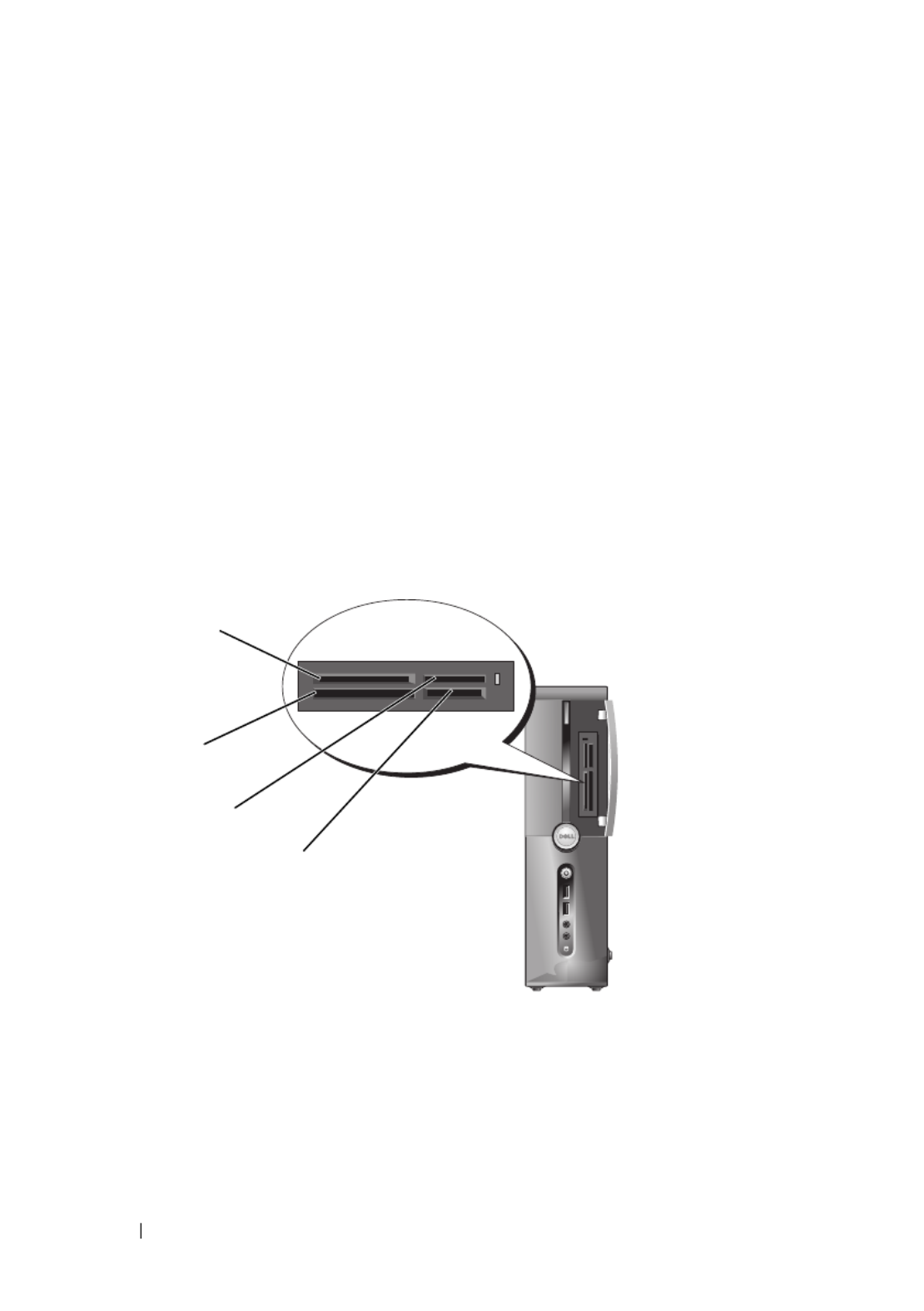
Using a Media Card Reader (Optional)
Use the Media Card Reader to transfer data directly to your computer.
The Media Card Reader supports the following memory types:
• xD-Picture Card
• SmartMedia (SMC)
• CompactFlash Type I and II (CF I/II)
• MicroDrive Card
• SecureDigital Card (SD)
• MultiMediaCard (MMC)
• Memory Stick (MS/MS Pro)
For information on installing a Media Card Reader, see "Installing a Media
Card Reader" on page 138.
1 xD-Picture Card and SmartMedia
(SMC)
2 CompactFlash Type I and II (CF I/II)
and MicroDrive Card
3 Memory Stick (MS/MS Pro) 4 SecureDigital Card (SD)/
MultiMediaCard (MMC)
1
3
4
2

Setting Up and Using Your Computer 31
To use the Media Card Reader:
1
Check the media or card to determine the proper orientation for insertion.
2
Slide the media or card into the appropriate slot until it is completely
seated in the connector.
If you encounter resistance, do not force the media or card. Check the card
orientation and try again.
Connecting Two Monitors
CAUTION: Before you begin any of the procedures in this section, follow the
safety instructions in the Product Information Guide.
If you purchased a graphics card that supports dual monitors, follow these
instructions to connect and enable your monitors. The instructions tell you
how to connect either two monitors (each with a VGA connector), one monitor
with a VGA connector and one monitor with a DVI connector, or a TV.
NOTICE: If you are connecting two monitors that have VGA connectors, you must
have the optional DVI adapter to connect the cable. If you are connecting two flat-
panel monitors, at least one of them must have a VGA connector. If you are
connecting a TV, you may connect only one monitor (VGA or DVI) in addition to
the TV.
Connecting Two Monitors With VGA Connectors
1
Follow the procedures in "Before You Begin" on page 99.
NOTE: If your computer has integrated video, do not connect either monitor to the
integrated video connector. If the integrated video connector is covered by a cap,
do not remove the cap to connect the monitor or the monitor will not function.
2
Connect one of the monitors to the VGA (blue) connector on the back of
the computer.
3
Connect the other monitor to the optional DVI adapter and connect the
DVI adapter to the DVI (white) connector on the back of the computer.

32 Setting Up and Using Your Computer
Connecting One Monitor With a VGA Connector and One Monitor With a
DVI Connector
1
Follow the procedures in "Before You Begin" on page 99.
2
Connect the VGA connector on the monitor to the VGA (blue) connector
on the back of the computer.
3
Connect the DVI connector on the other monitor to the DVI (white)
connector on the back of the computer.
Connecting a TV
NOTE: You must purchase an S-video cable, available at most consumer
electronics stores, to connect a TV to your computer. It is not included with your
computer.
1
Follow the procedures in "Before You Begin" on page 99.
2
Connect one end of the S-video cable to the optional TV-OUT connector
on the back of the computer.
1 optional DVI adapter 2 DVI (white) connector
3 TV-OUT connector 4 VGA (blue) connector
*May not be present on your computer
4
2*
1
3*

Setting Up and Using Your Computer 33
3
Connect the other end of the S-video cable to the S-video input connector
on your TV.
4
Connect the VGA or DVI monitor.
Changing the Display Settings
1
After you connect the monitor(s) or TV, turn on the computer.
The Microsoft
®
Windows
®
desktop displays on the primary monitor.
2
Enable clone mode or extended desktop mode in the display settings.
• In clone mode, both monitors display the same image.
• In extended desktop mode, you can drag objects from one screen to
the other, effectively doubling the amount of viewable work space.
For information on changing the display settings for your graphics card, go to
support.dell.com.
Power Management Options in Windows XP
The Microsoft Windows XP power management features can reduce the
amount of electricity your computer uses when it is on and you are not using
it. You can reduce power to just the monitor or the hard drive, or you can use
standby mode or hibernate mode to reduce power to the entire computer.
When the computer exits from a power conservation mode, it returns to the
operating state it was in prior to entering the mode.
NOTE: Windows XP Professional includes security and networking features not
available in Windows XP Home Edition. When a Windows XP Professional
computer is connected to a network, different options related to security and
networking appear in certain windows.
NOTE: The procedures to activate the standby and hibernate modes may vary
according to your operating system.
Standby Mode
Standby mode conserves power by turning off the display and the hard drive
after a designated period of time, known as a time-out. When the computer
exits from standby mode, it returns to the operating state it was in prior to
entering standby mode.
NOTICE: If your computer loses power while in standby mode, it may lose data.

34 Setting Up and Using Your Computer
To set standby mode to automatically activate after a defined period of
inactivity:
1
Click
Start
→
Control Panel
→
Pick a category
→
Performance and
Maintenance
.
2
Under
or pick a Control Panel icon
, click
Power Options
.
To immediately activate standby mode without a period of inactivity, click
Start
→
Turn Off Computer
→
Stand by.
To exit from standby mode, press a key on the keyboard or move the mouse.
Hibernate Mode
Hibernate mode conserves power by copying system data to a reserved area on
the hard drive, and then completely turning off the computer. When the
computer exits from hibernate mode, the desktop is restored to the state it
was in prior to entering hibernate mode.
To activate hibernate mode:
1
Click
Start
→
Control Panel
→
Pick a category
→
Performance and
Maintenance
.
2
Under
or pick a Control Panel icon
, click
Power Options
.
3
Define your hibernate settings on the
Power Schemes
tab,
Advanced
tab,
and
Hibernate
tab.
To exit hibernate mode, press the power button. The computer may take a
short time to exit hibernate mode. Because the keyboard and mouse do not
function in hibernate mode, pressing a key on the keyboard or moving the
mouse does not bring the computer out of hibernation.
Because hibernate mode requires a special file on your hard drive with enough
disk space to store the contents of the computer memory, Dell creates an
appropriately sized hibernate mode file before shipping the computer to you.
If the computer’s hard drive becomes corrupted, Windows XP recreates the
hibernate file automatically.

Setting Up and Using Your Computer 35
Power Options Properties
Define your standby mode settings, hibernate mode settings, and other power
settings in the Power Options Properties window. To access the Power
Options Properties window:
1
Click
Start
→
Control Panel
→
Pick a category
→
Performance and
Maintenance
.
2
Under
or pick a Control Panel icon
, click
Power Options
.
3
Define your power settings on the
Power Schemes
tab,
Advanced
tab, and
Hibernate
tab.
Power Schemes Tab
Each standard power setting is called a scheme. If you want to select one of
the standard Windows schemes installed on your computer, choose a scheme
from the Power schemes drop-down menu. The settings for each scheme
appear in the fields below the scheme name. Each scheme has different
settings for starting standby mode, hibernate mode, turning off the monitor,
and turning off the hard drive.
NOTICE: If you set the hard drive to time-out before the monitor does, your
computer may appear to be locked up. To recover, press any key on the keyboard or
click the mouse. To avoid this problem, always set the monitor to time-out before the
hard drive.
The Power schemes drop-down menu displays the following schemes:
•
Always On
(default) — If you want to use your computer with no power
conservation.
•
Home/Office Desk
— If you want your home or office computer to run
with little power conservation.
•
Portable/Laptop
— If your computer is a portable computer that you use
for traveling.
•
Presentation
— If you want your computer to run without interruption
(using no power conservation).
•
Minimal Power Management
— If you want your computer to run with
minimal power conservation.
•
Max Battery
— If your computer is a portable computer and you run your
computer from batteries for extended periods of time.

36 Setting Up and Using Your Computer
If you want to change the default settings for a scheme, click the drop-down
menu in the Turn off monitor, Turn off hard disks, System stand by, or
System hibernates field, and then select a time-out from the displayed list.
Changing the time-out for a scheme field permanently changes the default
settings for that scheme, unless you click and enter a new name for Save As
the changed scheme.
Advanced Tab
The Advanced tab allows you to:
• Place the power options icon in the Windows taskbar for quick
access.
• Set the computer to prompt you for your Windows password before the
computer exits from standby mode or hibernate mode.
• Program the power button to activate standby mode, activate hibernate
mode, or turn off the computer.
To program these functions, click an option from the corresponding drop-
down menu and click OK.
Hibernate Tab
The Hibernate tab allows you to enable hibernate mode. If you want to use
the hibernate settings as defined on the Power Schemes tab, click the Enable
hibernation Hibernate check box on the tab.
Additional Information
For more information on power management options:
1
Click
Start
→
Help and Support
→
Performance and maintenance
.
2
In the
Performance and maintenance
window, click
Conserving power on
your computer
.
Power Management Options in Windows Vista
The Microsoft Vista™ power management features are designed to reduce the
amount of electricity your computer uses when it is on and you are not using
it. You can reduce power to just the monitor or the hard drive. Windows Vista
sets the default "off" state to standby mode, or you can set hibernate mode to
reduce power even further.

38 Setting Up and Using Your Computer
To exit from standby mode, press a key on the keyboard or move the mouse.
NOTICE: If your computer loses power while in standby mode, it may lose data.
Windows Vista has a new feature called Hybrid Sleep mode - this saves the data
into a file and also puts the system into standby. If you lose power, the system will
have retained your data on the hard drive and resumes to the same state you left it.
Go to Help and Support and search for hybrid sleep for further information. Hybrid
Sleep provides fast wake if the system is in standby, but also keeps your data safe
by storing it to the hard drive.
Hibernate Mode
Hibernate mode conserves power by copying system data to a reserved area on
the hard drive and then completely turning off the computer. When the
computer exits from hibernate mode, the desktop is restored to the state it
was in before it entered hibernate mode. Windows Vista may mask Hibernate
from the user if Hybrid Sleep is enabled. For additional information, go to
Help and Support and search for hibernate.
To activate hibernate mode immediately (if available):
1
Click
Start
and click the
arrow
.
2
Select
Hibernate
from the list.
To exit from hibernate mode, press the power button. The computer may
take a short time to exit from hibernate mode. Pressing a key on the keyboard
or moving the mouse does not bring the computer out of hibernation,
because the keyboard and the mouse do not function when the computer is in
hibernate mode.
Because hibernate mode requires a special file on your hard drive with enough
disk space to store the contents of the computer memory, Dell creates an
appropriately sized hibernate mode file before shipping the computer to you.
If the computer's hard drive becomes corrupted, Windows Vista recreates the
hibernate file automatically.
Power Plan Properties
You can define standby mode settings, display mode settings, hibernate mode
settings (if available), and other power settings in the Power Plan Properties
window.

Setting Up and Using Your Computer 39
To access the Power Plan Properties window:
1
Click
Start
and click
Control Panel
.
2
Under
Pick a category
, click
System and Maintenance
.
3
Under
System and Maintenance
, click
Power Options
.
4
This takes you to the main
Select a Power Plan
window.
5
In the
Select A Power Plan
window, you can change or modify power
settings.
To change the default settings for a plan:
1
Click
Start
and click
Control Panel
.
2
Under
Pick a category
, click
System and Maintenance
.
3
Under
System and Maintenance
, click
Power Options
.
In the Power Options window, click Change Plan Settings to change settings
such as:
• Require a password on wakeup.
• Choose what power buttons do.
• Create a power plan (you can choose the settings you want and create a
custom power plan here).
• Choose when to turn off the display.
• Change when the computer sleeps.
Advanced Tab
The Advanced tab allows you to set many different settings beyond the basic
settings. If you do not know or are not sure what to set, leave the settings at
the default.
To access the advanced settings:
1
Choose the
Power Plan
you want to change.
2
Click
Change Plan Settings
from just below the plan name.
3
Click
Change Advanced Power Settings
.
CAUTION: There are many different settings in the Power Options, Advanced
Settings dialog box. Use care when making setting changes.
Click
Start
and go to Help and Support for more information.

40 Setting Up and Using Your Computer
Enabling SpeedStep™ Technology
SpeedStep technology controls your computer's processor performance
automatically, dynamically adjusting the operating frequency and voltage,
according to the task at hand. When an application does not require full
performance, significant amounts of power can be saved. Performance is
designed to still be responsive, with maximum processor performance being
delivered when required, and automatic power savings when possible.
Windows Vista automatically sets Intel Speedstep technologies in the Dell
Recommended, Balanced, and Power Saver power plans. It is disabled in the
High Performance power plan.
About RAID Configurations
This section provides an overview of the RAID configuration that you might
have selected when you purchased your computer. Although several RAID
configurations are available, Dell offers only RAID level 1 for its Vostro
computers. RAID level 1 configuration is recommended for the data integrity
requirements of digital photography and audio.
The Intel RAID controller on your computer can only create a RAID volume
using two physical drives. If a third drive is present, then that drive cannot be
made part of a RAID volume using the Intel RAID configuration program,
although it can be used as a spare drive in a RAID 1 configuration (see
"Creating a Spare Hard Drive" on page 46). However, if four drives are present
in your computer, then each pair of drives can be set as a RAID level 1
volume. The drives should be the same size in order to ensure that the larger
drive does not contain unallocated (and therefore unusable) space.
RAID Level 1 Configuration
RAID level 1 uses a data-redundancy storage technique known as "mirroring."
When data is written to the primary drive, it is then duplicated, or mirrored,
on the other drive. A RAID level 1 configuration sacrifices high data access
rates for its data redundancy advantages.

Setting Up and Using Your Computer 41
If a drive failure occurs, subsequent read and write operations are directed to
the surviving drive. A replacement drive can then be rebuilt using the data
from the surviving drive. Also, because data is duplicated on both drives, two
120-GB RAID level 1 drives collectively have a maximum of 120 GB on which
to store data.
NOTE: In a RAID level 1 configuration, the size of the configuration is equal to the
size of the smallest drive in the configuration.
Configuring Your Hard Drives for RAID
At some point you may want to configure your computer for RAID if you did
not select a RAID configuration when you purchased your computer. You
must have at least two hard drives installed in your computer to set up a
RAID configuration. For instructions on how to install a hard drive, see "Hard
Drives" on page 126.
You can use one of two methods to configure RAID hard drive volumes. One
method uses the Intel
®
Option ROM utility, and is performed before you
install the operating system onto the hard drive. The second method uses the
Intel Matrix Storage Manager or Intel Storage Utility, and this method is
performed after you have installed the operating system and the Intel Storage
hard drive 1
segment 1
segment 2
segment 3
hard drive 2
segment 4
segment 5
segment 6
segment 1 duplicated
segment 2 duplicated
segment 3 duplicated
segment 4 duplicated
segment 5 duplicated
segment 6 duplicated
serial ATA RAID
configured for
RAID level 1

42 Setting Up and Using Your Computer
Utility. Both methods require that you set your computer to RAID-enabled
mode before starting any of the RAID configuration procedures in this
document.
Setting Your Computer to RAID-Enabled Mode
1
Enter the system setup (see "Entering System Setup" on page 170).
2
Press the left- and right-arrow keys to highlight
Drives
tab.
3
Press the up- and down-arrow keys to highlight
Drive Controller
, then
press <Enter>.
4
Press the up- and down-arrow keys to highlight
RAID On
, and then press
<Enter>.
NOTE: For more information about RAID options, see "System Setup Options"
on page 172.
5
Press the up- and down-arrow keys to highlight
Save/Exit
, and press
<Enter> to exit system setup and resume the boot process.
Configuring for RAID Using the Intel
®
Option ROM Utility
NOTE: Although any size drives may be used to create a RAID configuration using
the Intel Option ROM utility, ideally the drives should be of equal size. In a RAID
level 1 configuration, the size of the array will be the smaller of the two disks used.
Creating a RAID Level 1 Configuration
1
Set your computer to RAID-enabled mode (see "Setting Your Computer to
RAID-Enabled Mode" on page 42).
2
Press <Ctrl><i> when you are prompted to enter Intel RAID Option
ROM.
3
Use the up- and down-arrow keys to highlight
Create RAID Volume
, and
press <Enter>.
4
Enter a RAID volume name or accept the default, and press <Enter>.
5
Use the up- and down-arrow keys to select
RAID1(Mirror)
, and press
<Enter>.
6
If there are more than two hard disks available, use the up- and down-
arrow keys and space bar to select the two disks you want to use to make up
your array, and then press <Enter>.

Setting Up and Using Your Computer 43
7
Select the desired capacity for the volume, and press <Enter>. The
default value is the maximum available size.
8
Press <Enter> to create the volume.
9
Press <y> to confirm that you want to create the RAID volume.
10
Confirm that the correct volume configuration is displayed on the main
Intel Option ROM screen.
11
Use the up- and down-arrow keys to select
Exit
, and press <Enter>.
12
Install the operating system.
Deleting a RAID Volume
NOTE: When you perform this operation, all data on the RAID drives will be lost.
NOTE: If your computer currently boots to RAID and you delete the RAID volume in
the Intel RAID Option ROM, your computer will become unbootable.
1
Press <Ctrl><i> when you are prompted to enter the Intel RAID Option
ROM utility.
2
Use the up- and down-arrow keys to highlight
Delete RAID Volume
, and
press <Enter>.
3
Use the up- and down-arrow keys to highlight the RAID volume you want
to delete, and press <Delete>.
4
Press <y> to confirm the deletion of the RAID volume.
5
Press <Esc> to exit the Intel Option ROM utility.
Configuring for RAID Using the Intel
®
Matrix Storage Manager
If you already have one hard drive with the operating system installed on it,
and you want to add a second hard drive and reconfigure both drives into a
RAID volume without losing the existing operating system and any data, you
need to use the migrating option (see "Migrating to a RAID 1 Volume" on
page 45 or "Migrating to a RAID 1 Volume" on page 45). Create a RAID 1
Volume only when:
• You are adding two new drives to an existing single-drive computer (and
the operating system is on the single drive), and you want to configure the
two new drives into a RAID volume.

Setting Up and Using Your Computer 45
Deleting a RAID Volume
NOTE: While this procedure deletes the RAID 1 volume, it also splits the RAID 1
volume into two non-RAID hard drives with a partition, and leaves any existing data
files intact. Deleting a RAID 0 volume, however, destroys all data on the volume.
1
In Windows XP, click
Start
→
All Programs
→
Intel
®
Matrix Storage
Manager
→
Intel Matrix Storage Console
to launch the Intel
®
Storage
Utility.
In Windows Vista, click
Start
→
Programs
→
Intel
®
Matrix Storage
Manager
→
Intel Matrix Storage Manager
to launch the Intel
®
Storage
Utility.
2
Right-click the
Volume
icon of the RAID volume you want to delete, and
select
Delete Volume
.
3
On the
Delete RAID Volume Wizard
screen, click
Next
.
4
Highlight the RAID volume you want to delete in the
Available
box, click
the right-arrow button to move the highlighted RAID volume into the
Selected
box, and then click
Next
.
5
Click
Finish
to delete the volume.
Migrating to a RAID 1 Volume
1
Set your computer to RAID-enabled mode (see "Setting Your Computer to
RAID-Enabled Mode" on page 42).
2
In Windows XP, click
Start
→
All Programs
→
Intel
®
Matrix Storage
Manager
→
Intel Matrix Storage Console
to launch the Intel
®
Storage
Utility.
In Windows Vista, click
Start
→
Programs
→
Intel
®
Matrix Storage
Manager
→
Intel Matrix Storage Manager
to launch the Intel
®
Storage
Utility.
NOTE: If you do not see an Actions menu option, you have not yet set your
computer to RAID-enabled mode (see "Setting Your Computer to RAID-Enabled
Mode" on page 42).
3
On the
Actions
menu, click
Create RAID Volume From Existing Hard
Drive
to launch the Migration Wizard.
4
Click
Next
on the first Migration Wizard screen.
5
Enter a RAID volume name or accept the default.

46 Setting Up and Using Your Computer
6
From the drop-down box, select
RAID 1
as the RAID level
.
NOTE: Select the hard drive that already has the data or operating system files that
you want to maintain on the RAID volume as your source hard drive.
7
On the
Select Source Hard Drive
screen, double-click the hard drive from
which you want to migrate, and click
Next
.
8
On the
Select Member Hard Drive
screen, double-click the hard drive to
select the member drive that you want to act as the mirror in the array, and
click
Next
.
9
On the
Specify Volume Size
screen, select the volume size you want, and
click
Next
.
NOTE: In the following step, you will lose all data contained on the member drive.
10
Click
Finish
to start migrating, or click
Back
to make changes. You can use
your computer normally during migration process.
Creating a Spare Hard Drive
A spare hard drive may be created with a RAID 1 array. The spare hard drive
will not be recognized by the operating system, but you will be able to see the
spare drive from within Disk Manager or the Intel Option ROM Utility.
When a member of the RAID 1 array is broken, the computer automatically
rebuilds the mirror array using the spare hard drive as the broken member’s
replacement.
To Mark a Drive as a Spare Hard Drive:
1
In Windows XP, click
Start
→
All Programs
→
Intel
®
Matrix Storage
Manager
→
Intel Matrix Storage Console
to launch the Intel
®
Storage
Utility.
In Windows Vista, click
Start
→
Programs
→
Intel
®
Matrix Storage
Manager
→
Intel Matrix Storage Manager
to launch the Intel
®
Storage
Utility.
2
Right-click the hard drive you want to mark as a spare hard drive.
3
Click
Mark as Spare
.
To Remove Spare Marking From a Spare Hard Drive:
1
Right-click the spare hard drive icon.
2
Click
Reset Hard Drive to Non-RAID.

Setting Up and Using Your Computer 47
Rebuilding a Degraded RAID 1 Volume
If your computer does not have a spare hard drive, and the computer has
reported a degraded RAID 1 volume, you can manually rebuild the
computer’s redundancy mirror to a new hard drive by performing the
following steps:
1
In Windows XP, click
Start
→
All Programs
→
Intel
®
Matrix Storage
Manager
→
Intel Matrix Storage Console
to launch the Intel
®
Storage
Utility.
In Windows Vista, click
Start
→
Programs
→
Intel
®
Matrix Storage
Manager
→
Intel Matrix Storage Manager
to launch the Intel
®
Storage
Utility.
2
Right-click the available hard drive to which you want to rebuild the
RAID 1 volume, and click
Rebuild to this Disk
.
NOTE: You can use your computer while the computer is rebuilding the RAID 1
volume.
Transferring Information to a New Computer
You can use your operating system "wizards" to help you transfer files and
other data from one computer to another—for example, from an old
computer to a new computer. For instructions, see the following section that
corresponds to the operating system your computer is running.
Transferring Information using Windows XP
The Microsoft Windows XP operating system provides the Files and Settings
Transfer Wizard to move data from a source computer to a new computer.
You can transfer data, such as:
• E-mail messages
• Toolbar settings
• Window sizes
• Internet bookmarks
You can transfer the data to the new computer over a network or serial
connection, or you can store it on removable media, such as a writable CD,
for transfer to the new computer.

48 Setting Up and Using Your Computer
NOTE: You can transfer information from an old computer to a new computer by
directly connecting a serial cable to the input/output (I/O) ports of the two
computers. To transfer data over a serial connection, you must access the Network
Connections utility from the Control Panel and perform additional configuration
steps, such as setting up an advanced connection and designating the host
computer and the guest computer.
For instructions on setting up a direct cable connection between two computers,
see Microsoft Knowledge Base Article #305621, titled How to Set Up a Direct Cable
Connection Between Two Computers in Windows XP. This information may not be
available in certain countries.
For transferring information to a new computer, you must run the Files and
Settings Transfer Wizard. You can use the optional Operating System media
for this process or you can create a wizard disk with the Files and Settings
Transfer Wizard.
Running the Files and Settings Transfer Wizard With the Operating System Media
NOTE: This procedure requires the Operating System media. This media is optional
and may not be included with certain computers.
To prepare a new computer for the file transfer:
1
Open the Files and Settings Transfer Wizard: click
Start
→
All Programs
→
Accessories
→
System Tools
→
Files and Settings Transfer Wizard
.
2
When the
Files and Settings Transfer Wizard
welcome screen appears,
click
Next
.
3
On the
Which computer is this?
screen, click
New Computer
→
Next
.
4
On the
Do you have a Windows XP CD?
screen, click
I will use the wizard
from the Windows XP CD
→
Next
.
5
When the
Now go to your old computer
screen appears, go to your old or
source computer. Do
not
click
Next
at this time.
To copy data from the old computer:
1
On the old computer, insert the Windows XP
Operating System
media.
2
On the
Welcome to Microsoft Windows XP
screen, click
Perform
additional tasks
.
3
Under
What do you want to do?
, click
Transfer files and settings
→
Next
.
4
On the
Which computer is this?
screen, click
Old Computer
→
Next
.
Product specificaties
| Merk: | Dell |
| Categorie: | Desktop |
| Model: | Vostro 200 |
Heb je hulp nodig?
Als je hulp nodig hebt met Dell Vostro 200 stel dan hieronder een vraag en andere gebruikers zullen je antwoorden
Handleiding Desktop Dell

8 Juli 2024
10 Juni 2024
28 Mei 2024
6 December 2023
29 November 2023
29 November 2023
29 November 2023
29 November 2023
29 November 2023
29 November 2023
Handleiding Desktop
- Desktop HP
- Desktop Sony
- Desktop Samsung
- Desktop LG
- Desktop Asus
- Desktop Medion
- Desktop Toshiba
- Desktop VTech
- Desktop Acer
- Desktop Alienware
- Desktop AOC
- Desktop AOpen
- Desktop Apple
- Desktop Asrock
- Desktop Axis
- Desktop BenQ
- Desktop Emachines
- Desktop Faytech
- Desktop Fujitsu
- Desktop Gigabyte
- Desktop Haier
- Desktop Ibm
- Desktop InFocus
- Desktop Kobo
- Desktop Kogan
- Desktop Lenovo
- Desktop Maxdata
- Desktop Microsoft
- Desktop Mio
- Desktop MP
- Desktop MSI
- Desktop Nec
- Desktop Packard Bell
- Desktop Peaq
- Desktop Razer
- Desktop Seagate
- Desktop Sharkoon
- Desktop Sharp
- Desktop Targa
- Desktop Trekstor
- Desktop Viewsonic
- Desktop Wehkamp
- Desktop Woood
- Desktop ZTE
- Desktop Jysk
- Desktop ONYX
- Desktop Optoma
- Desktop Parisot
- Desktop Intel
- Desktop BDI
- Desktop Tripp Lite
- Desktop LC-Power
- Desktop Zoostorm
- Desktop ZOTAC
- Desktop Planar
- Desktop Supermicro
- Desktop ELO
- Desktop Shuttle
- Desktop VXL
- Desktop ECS
- Desktop Vorago
- Desktop Promethean
- Desktop Foxconn
- Desktop Advantech
- Desktop Moxa
- Desktop Kramer
- Desktop Elitegroup
- Desktop Smart Things
- Desktop System76
- Desktop Bestar
- Desktop Pelco
- Desktop Cybernet
- Desktop Altra
- Desktop Dell Wyse
- Desktop NComputing
- Desktop MvixUSA
- Desktop AIS
- Desktop Wyse
- Desktop Kendall Howard
Nieuwste handleidingen voor Desktop

9 April 2025

1 April 2025
1 April 2025

28 Maart 2025
27 Maart 2025

25 Februari 2025
25 Februari 2025
25 Februari 2025
24 Februari 2025
10 Februari 2025