Dell OptiPlex 7050 Handleiding
Lees hieronder de 📖 handleiding in het Nederlandse voor Dell OptiPlex 7050 (81 pagina's) in de categorie Desktop. Deze handleiding was nuttig voor 32 personen en werd door 2 gebruikers gemiddeld met 4.5 sterren beoordeeld
Pagina 1/81

OptiPle
OptiPle
OptiPle
OptiPleOptiPlex 7050 T
x 7050 T
x 7050 T
x 7050 Tx 7050 T
ow
ow
ow
owower
er
er
erer
Owner's Manual
Regulatory Model: D
Regulatory Model: D
Regulatory Model: D
Regulatory Model: DRegulatory Model: D18M
18M
18M
18M18M
Regulatory T
Regulatory T
Regulatory T
Regulatory TRegulatory T
ype: D18M003
ype: D18M003
ype: D18M003
ype: D18M003ype: D18M003

Notes, cautions, and warnings
NOTE:
NOTE:
NOTE:
NOTE: NOTE: A NO
A NO
A NO
A NOA NOTE indicat
TE indicat
TE indicat
TE indicatTE indicates important inf
es important inf
es important inf
es important infes important information that helps y
ormation that helps y
ormation that helps y
ormation that helps yormation that helps you make bett
ou make bett
ou make bett
ou make bettou make better use of your pr
er use of your pr
er use of your pr
er use of your prer use of your product.
oduct.
oduct.
oduct.oduct.
CA
CA
CA
CACAUTION:
UTION:
UTION:
UTION: UTION: A CA
A CA
A CA
A CAA CAUTION indicat
UTION indicat
UTION indicat
UTION indicatUTION indicates either poten
es either poten
es either poten
es either potenes either potential damage to har
tial damage to har
tial damage to har
tial damage to hartial damage to hardwar
dwar
dwar
dwardware or loss of dat
e or loss of dat
e or loss of dat
e or loss of date or loss of data and tells you ho
a and tells you ho
a and tells you ho
a and tells you hoa and tells you how to a
w to a
w to a
w to aw to avoid the pr
void the pr
void the pr
void the prvoid the problem.
oblem.
oblem.
oblem.oblem.
W
W
W
WWARNING:
ARNING:
ARNING:
ARNING: ARNING: A WARNING indica
A WARNING indica
A WARNING indica
A WARNING indicaA WARNING indicates a pot
tes a pot
tes a pot
tes a pottes a potential f
ential f
ential f
ential fential for property damage
or property damage
or property damage
or property damageor property damage, personal injury
, personal injury
, personal injury
, personal injury, personal injury, or death.
, or death.
, or death.
, or death., or death.
© 2017 Dell Inc. or its subsidiaries
2017 Dell Inc. or its subsidiaries
2017 Dell Inc. or its subsidiaries
2017 Dell Inc. or its subsidiaries 2017 Dell Inc. or its subsidiaries. All rights r
. All rights r
. All rights r
. All rights r. All rights reserved.
eserved.
eserved.
eserved.eserved. Dell, EMC, and other trademarks are trademarks of Dell Inc. or its subsidiaries. Other trademarks
may be trademarks of their respective owners.
2017 - 02
Rev. A00

Con
Con
Con
ConCont
t
t
tten
en
en
enent
t
t
tts
s
s
ss
1 W
1 W
1 W
1 W1 Working on your comput
orking on your comput
orking on your comput
orking on your computorking on your computer............................................................................................................................. 7
er............................................................................................................................. 7
er............................................................................................................................. 7
er............................................................................................................................. 7er............................................................................................................................. 7
Safety instructions............................................................................................................................................................. 7
Before working inside your computer.............................................................................................................................. 7
Turning your computer................................................................................................................................................ 8o
Turning your computer — Windows 10...............................................................................................................8o
Turning your computer — Windows 7.................................................................................................................8o
After working inside your computer.................................................................................................................................8
2 Removing and inst
2 Removing and inst
2 Removing and inst
2 Removing and inst2 Removing and installing components.............................................................................................................
alling components.............................................................................................................
alling components.............................................................................................................
alling components.............................................................................................................alling components............................................................................................................. 9
9
9
99
Recommended tools.......................................................................................................................................................... 9
Back cover.......................................................................................................................................................................... 9
Removing cover........................................................................................................................................................... 9
Installing cover............................................................................................................................................................. 11
Front Bezel......................................................................................................................................................................... 11
Removing bezel............................................................................................................................................................11
Installing bezel............................................................................................................................................................. 12
Opening the front panel door..........................................................................................................................................12
Storage...............................................................................................................................................................................13
Removing 3.5–inch hard drive assembly................................................................................................................. 13
Removing 3.5–inch hard drive from the hard drive bracket................................................................................. 15
Installing 3.5–inch hard drive assembly....................................................................................................................16
Installing the 3.5–inch hard drive into the hard drive bracket...............................................................................16
Removing the 2.5–inch drive assembly...................................................................................................................16
Removing the 2.5–inch drive from the drive bracket............................................................................................ 17
Installing the 2.5-inch drive assembly...................................................................................................................... 18
Optical drive...................................................................................................................................................................... 18
Removing optical drive...............................................................................................................................................18
Installing optical drive................................................................................................................................................ 20
M.2 PCIe SSD ................................................................................................................................................................. 20
Removing optional M.2 PCIe SSD .......................................................................................................................... 20
Installing optional M.2 PCIe SSD ............................................................................................................................. 21
SD card reader..................................................................................................................................................................22
Removing SD card reader......................................................................................................................................... 22
Installing SD card reader............................................................................................................................................23
Memory module............................................................................................................................................................... 23
Removing memory module....................................................................................................................................... 23
Installing memory module..........................................................................................................................................23
Expansion card................................................................................................................................................................. 24
Removing PCIe expansion card................................................................................................................................24
Installing PCIe expansion card..................................................................................................................................25
Power supply unit.............................................................................................................................................................26
Removing power supply unit (PSU)........................................................................................................................ 26
Installing power supply unit (PSU)........................................................................................................................... 27
Contents 3

VGA daughter board........................................................................................................................................................28
Removing VGA daughter board............................................................................................................................... 28
Installing VGA daughter board..................................................................................................................................29
Intrusion switch................................................................................................................................................................29
Removing intrusion switch........................................................................................................................................29
Installing intrusion switch.......................................................................................................................................... 30
Power switch....................................................................................................................................................................30
Removing power switch............................................................................................................................................30
Installing power switch.............................................................................................................................................. 32
Speaker............................................................................................................................................................................. 32
Removing speaker......................................................................................................................................................32
Installing speaker........................................................................................................................................................34
Coin cell battery............................................................................................................................................................... 34
Removing coin cell battery........................................................................................................................................34
Installing the coin cell battery...................................................................................................................................35
Heat sink assembly.......................................................................................................................................................... 36
Removing heat sink assembly.................................................................................................................................. 36
Installing heat sink assembly..................................................................................................................................... 37
Processor.......................................................................................................................................................................... 37
Removing processor.................................................................................................................................................. 37
Installing processor.................................................................................................................................................... 38
System fan........................................................................................................................................................................39
Removing system fan................................................................................................................................................39
Installing system fan.................................................................................................................................................. 40
System board................................................................................................................................................................... 40
Removing system board............................................................................................................................................40
Installing the system board....................................................................................................................................... 43
3 M.2 Int
3 M.2 Int
3 M.2 Int
3 M.2 Int3 M.2 Intel Optane Memory Module 16 GB.....................................................................................................
el Optane Memory Module 16 GB.....................................................................................................
el Optane Memory Module 16 GB.....................................................................................................
el Optane Memory Module 16 GB.....................................................................................................el Optane Memory Module 16 GB..................................................................................................... 45
45
45
4545
Overview...........................................................................................................................................................................45
Intel®OptaneTM Memory Module Driver Requirements........................................................................................... 45
M.2 Intel Optane Memory Module 16 GB..................................................................................................................... 45
Product ..................................................................................................................................................... 47specications
Environmental Conditions............................................................................................................................................... 48
Troubleshooting................................................................................................................................................................49
4 T
4 T
4 T
4 T4 Technology and componen
echnology and componen
echnology and componen
echnology and componenechnology and components....................................................................................................................... 50
ts....................................................................................................................... 50
ts....................................................................................................................... 50
ts....................................................................................................................... 50ts....................................................................................................................... 50
USB features.................................................................................................................................................................... 50
USB 3.0/USB 3.1 Gen 1 (SuperSpeed USB)...........................................................................................................50
Speed.......................................................................................................................................................................... 50
Applications................................................................................................................................................................. 51
Compatibility...............................................................................................................................................................52
HDMI 1.4............................................................................................................................................................................52
HDMI 1.4 Features......................................................................................................................................................52
Advantages of HDMI.................................................................................................................................................52
5 Syst
5 Syst
5 Syst
5 Syst5 System setup...............................................................................................................................................54
em setup...............................................................................................................................................54
em setup...............................................................................................................................................54
em setup...............................................................................................................................................54em setup...............................................................................................................................................54
4 Contents

Boot Sequence.................................................................................................................................................................54
Navigation Keys................................................................................................................................................................54
System and setup password.......................................................................................................................................... 55
Assigning a system password and setup password...............................................................................................55
Deleting or changing an existing system and/or setup password....................................................................... 56
System Setup options..................................................................................................................................................... 56
Updating the BIOS in Windows .....................................................................................................................................63
Updating your system BIOS using a USB drive.................................................................................................. 63ash
Enabling smart power on................................................................................................................................................ 64
6 Softwar
6 Softwar
6 Softwar
6 Softwar6 Software......................................................................................................................................................65
e......................................................................................................................................................65
e......................................................................................................................................................65
e......................................................................................................................................................65e......................................................................................................................................................65
Supported operating systems........................................................................................................................................ 65
Downloading drivers........................................................................................................................................................ 65
Downloading the chipset driver..................................................................................................................................... 65
Intel chipset drivers....................................................................................................................................................66
Downloading graphic drivers.......................................................................................................................................... 66
Intel HD Graphics drivers...........................................................................................................................................67
Intel Wi-Fi and Bluetooth drivers....................................................................................................................................67
Downloading the Wi-Fi driver...................................................................................................................................67
Realtek HD audio drivers.................................................................................................................................................68
Downloading the audio driver...................................................................................................................................68
7 T
7 T
7 T
7 T7 Tr
r
r
rroubleshooting your comput
oubleshooting your comput
oubleshooting your comput
oubleshooting your computoubleshooting your computer................................................................................................................... 69
er................................................................................................................... 69
er................................................................................................................... 69
er................................................................................................................... 69er................................................................................................................... 69
Diagnostic power LED codes......................................................................................................................................... 69
Power LED issue.............................................................................................................................................................. 70
Dell Enhanced Pre-Boot System Assessment (ePSA) diagnostic 3.0....................................................................... 70
Running the ePSA diagnostics................................................................................................................................. 70
Diagnostic error messages...............................................................................................................................................71
System error messages................................................................................................................................................... 74
Verifying system memory in Windows 10 and Windows 7 ......................................................................................... 74
Windows 10................................................................................................................................................................. 74
Windows 7...................................................................................................................................................................74
Verifying system memory in setup...........................................................................................................................75
Testing memory using ePSA.....................................................................................................................................75
8 T
8 T
8 T
8 T8 Technical
echnical
echnical
echnical echnical specica
specica
specica
specicaspecications
tions
tions
tionstions...............................................................................................................................
...............................................................................................................................
...............................................................................................................................
.............................................................................................................................................................................................................................................................. 76
76
76
7676
Processor ..................................................................................................................................................76specications
Memory .....................................................................................................................................................77specications
Video ......................................................................................................................................................... 77specications
Audio ......................................................................................................................................................... 77specications
Communication ........................................................................................................................................77specications
Storage specications..................................................................................................................................................... 78
Ports and connectors ..............................................................................................................................78specications
Power supply ............................................................................................................................................78specications
Physical dimension .................................................................................................................................. 78specications
System board layout........................................................................................................................................................ 79
Controls and lights .................................................................................................................................. 80specications
Contents 5

Environmental specications.......................................................................................................................................... 80
9 Contac
9 Contac
9 Contac
9 Contac9 Contacting Dell.............................................................................................................................................
ting Dell.............................................................................................................................................
ting Dell.............................................................................................................................................
ting Dell.............................................................................................................................................ting Dell.............................................................................................................................................81
81
81
8181
6 Contents

W
W
W
WWorking on your comput
orking on your comput
orking on your comput
orking on your computorking on your computer
er
er
erer
Saf
Saf
Saf
SafSafety instruc
ety instruc
ety instruc
ety instrucety instructions
tions
tions
tionstions
Use the following safety guidelines to protect your computer from potential damage and to ensure your personal safety. Unless otherwise
noted, each procedure included in this document assumes that the following conditions exist:
• You have read the safety information that shipped with your computer.
• A component can be replaced or, if purchased separately, installed by performing the removal procedure in reverse order.
W
W
W
WWARNING:
ARNING:
ARNING:
ARNING: ARNING: Disconnect all power sour
Disconnect all power sour
Disconnect all power sour
Disconnect all power sourDisconnect all power sources bef
ces bef
ces bef
ces befces before opening the comput
ore opening the comput
ore opening the comput
ore opening the computore opening the computer cover or panels
er cover or panels
er cover or panels
er cover or panelser cover or panels. Aft
. Aft
. Aft
. Aft. After you
er you
er you
er you er you working inside the
working inside the
working inside the
working inside the working inside the
nish
nish
nish
nishnish
computer
computer
computer
computercomputer, r
, r
, r
, r, replace all cover
eplace all cover
eplace all cover
eplace all covereplace all covers, panels, and scr
s, panels, and scr
s, panels, and scr
s, panels, and scrs, panels, and screws bef
ews bef
ews bef
ews befews befor
or
or
orore connecting to the po
e connecting to the po
e connecting to the po
e connecting to the poe connecting to the power source
wer source
wer source
wer sourcewer source.
.
.
..
W
W
W
WWARNING:
ARNING:
ARNING:
ARNING: ARNING: Befor
Befor
Befor
BeforBefore working inside your comput
e working inside your comput
e working inside your comput
e working inside your compute working inside your computer
er
er
erer, r
, r
, r
, r, read the safe
ead the safe
ead the safe
ead the safeead the safety informa
ty informa
ty informa
ty informaty information that shipped with your computer
tion that shipped with your computer
tion that shipped with your computer
tion that shipped with your computertion that shipped with your computer
. For additional
. For additional
. For additional
. For additional . For additional
saf
saf
saf
safsafety best practices in
ety best practices in
ety best practices in
ety best practices inety best practices information, see the R
formation, see the R
formation, see the R
formation, see the Rformation, see the Regulatory Compliance Homepage a
egulatory Compliance Homepage a
egulatory Compliance Homepage a
egulatory Compliance Homepage aegulatory Compliance Homepage at www
t www
t www
t wwwt www.Dell.com/
.Dell.com/
.Dell.com/
.Dell.com/.Dell.com/r
r
r
rregulatory
egulatory
egulatory
egulatoryegulatory_
_
_
__compliance
compliance
compliance
compliance compliance
CA
CA
CA
CACAUTION:
UTION:
UTION:
UTION: UTION: Many r
Many r
Many r
Many rMany repairs may only be done b
epairs may only be done b
epairs may only be done b
epairs may only be done bepairs may only be done by a
y a
y a
y a y a service technician. Y
service technician. Y
service technician. Y
service technician. Y service technician. You should only perf
ou should only perf
ou should only perf
ou should only perfou should only perform troubleshoo
orm troubleshoo
orm troubleshoo
orm troubleshooorm troubleshooting and simple
ting and simple
ting and simple
ting and simple ting and simple
certied
certied
certied
certiedcertied
r
r
r
rrepairs as authorized in your pr
epairs as authorized in your pr
epairs as authorized in your pr
epairs as authorized in your prepairs as authorized in your product documentation, or as dir
oduct documentation, or as dir
oduct documentation, or as dir
oduct documentation, or as diroduct documentation, or as direct
ect
ect
ectected by the online or telephone service and support t
ed by the online or telephone service and support t
ed by the online or telephone service and support t
ed by the online or telephone service and support ted by the online or telephone service and support team. Damage
eam. Damage
eam. Damage
eam. Damage eam. Damage
due to servicing tha
due to servicing tha
due to servicing tha
due to servicing thadue to servicing that is not authorized by Dell is no
t is not authorized by Dell is no
t is not authorized by Dell is no
t is not authorized by Dell is not is not authorized by Dell is not cover
t cover
t cover
t covert covered by your w
ed by your w
ed by your w
ed by your wed by your warranty
arranty
arranty
arrantyarranty. Read and f
. Read and f
. Read and f
. Read and f. Read and follow the saf
ollow the saf
ollow the saf
ollow the safollow the safety instructions that came
ety instructions that came
ety instructions that came
ety instructions that came ety instructions that came
with the pr
with the pr
with the pr
with the prwith the product.
oduct.
oduct.
oduct.oduct.
CA
CA
CA
CACAUTION:
UTION:
UTION:
UTION: UTION: T
T
T
TT
o avoid electr
o avoid electr
o avoid electr
o avoid electro avoid electrostatic discharge
ostatic discharge
ostatic discharge
ostatic dischargeostatic discharge, ground y
, ground y
, ground y
, ground y, ground yourself by using a wrist gr
ourself by using a wrist gr
ourself by using a wrist gr
ourself by using a wrist grourself by using a wrist grounding strap or by periodically t
ounding strap or by periodically t
ounding strap or by periodically t
ounding strap or by periodically tounding strap or by periodically touching an
ouching an
ouching an
ouching an ouching an
unpaint
unpaint
unpaint
unpaintunpainted metal surface a
ed metal surface a
ed metal surface a
ed metal surface aed metal surface at the same time as touching a connect
t the same time as touching a connect
t the same time as touching a connect
t the same time as touching a connectt the same time as touching a connector on the back of the comput
or on the back of the comput
or on the back of the comput
or on the back of the computor on the back of the computer
er
er
erer.
.
.
..
CA
CA
CA
CACAUTION:
UTION:
UTION:
UTION: UTION: Handle components and car
Handle components and car
Handle components and car
Handle components and carHandle components and cards with car
ds with car
ds with car
ds with cards with care. Do not t
e. Do not t
e. Do not t
e. Do not te. Do not touch the components or cont
ouch the components or cont
ouch the components or cont
ouch the components or contouch the components or contacts on a car
acts on a car
acts on a car
acts on a caracts on a card. Hold a card b
d. Hold a card b
d. Hold a card b
d. Hold a card bd. Hold a card by its
y its
y its
y its y its
edges or by its me
edges or by its me
edges or by its me
edges or by its meedges or by its metal mounting brack
tal mounting brack
tal mounting brack
tal mounting bracktal mounting bracket. Hold a component such as a pr
et. Hold a component such as a pr
et. Hold a component such as a pr
et. Hold a component such as a pret. Hold a component such as a processor by its edges
ocessor by its edges
ocessor by its edges
ocessor by its edgesocessor by its edges, not by its pins
, not by its pins
, not by its pins
, not by its pins, not by its pins.
.
.
..
CA
CA
CA
CACAUTION:
UTION:
UTION:
UTION: UTION: When you disconnect a cable, pull on it
When you disconnect a cable, pull on it
When you disconnect a cable, pull on it
When you disconnect a cable, pull on itWhen you disconnect a cable, pull on its connector or on it
s connector or on it
s connector or on it
s connector or on its connector or on its pull-tab
s pull-tab
s pull-tab
s pull-tabs pull-tab, not on the cable itself
, not on the cable itself
, not on the cable itself
, not on the cable itself, not on the cable itself. Some cables have
. Some cables have
. Some cables have
. Some cables have . Some cables have
connect
connect
connect
connectconnectors with locking tabs; if you ar
ors with locking tabs; if you ar
ors with locking tabs; if you ar
ors with locking tabs; if you arors with locking tabs; if you are disconnecting this type of cable, pr
e disconnecting this type of cable, pr
e disconnecting this type of cable, pr
e disconnecting this type of cable, pre disconnecting this type of cable, press in on the locking tabs bef
ess in on the locking tabs bef
ess in on the locking tabs bef
ess in on the locking tabs befess in on the locking tabs before y
ore y
ore y
ore yore you disconnect the
ou disconnect the
ou disconnect the
ou disconnect the ou disconnect the
cable. As you pull connec
cable. As you pull connec
cable. As you pull connec
cable. As you pull conneccable. As you pull connectors apart, keep them e
tors apart, keep them e
tors apart, keep them e
tors apart, keep them etors apart, keep them evenly aligned to a
venly aligned to a
venly aligned to a
venly aligned to avenly aligned to avoid bending any connec
void bending any connec
void bending any connec
void bending any connecvoid bending any connector pins. Also
tor pins. Also
tor pins. Also
tor pins. Alsotor pins. Also, befor
, befor
, befor
, befor, before you connect a
e you connect a
e you connect a
e you connect a e you connect a
cable, ensur
cable, ensur
cable, ensur
cable, ensurcable, ensure that both connect
e that both connect
e that both connect
e that both connecte that both connectors ar
ors ar
ors ar
ors arors are corr
e corr
e corr
e corre correctly orient
ectly orient
ectly orient
ectly orientectly oriented and aligned.
ed and aligned.
ed and aligned.
ed and aligned.ed and aligned.
NOTE:
NOTE:
NOTE:
NOTE: NOTE: The color o
The color o
The color o
The color oThe color of your computer and certain componen
f your computer and certain componen
f your computer and certain componen
f your computer and certain componenf your computer and certain components may appear
ts may appear
ts may appear
ts may appear ts may appear dier
dier
dier
dierdierently
ently
ently
entlyently than shown in this document.
than shown in this document.
than shown in this document.
than shown in this document. than shown in this document.
Bef
Bef
Bef
BefBefor
or
or
orore working inside y
e working inside y
e working inside y
e working inside ye working inside your comput
our comput
our comput
our computour computer
er
er
erer
To avoid damaging your computer, perform the following steps before you begin working inside the computer.
1 Ensure that you follow the Safety instructions.
2 Ensure that your work surface is and clean to prevent the computer cover from being scratched.at
3 Ensure you follow the Turning o your computer.
4 Disconnect all network cables from the computer.
CA
CA
CA
CACAUTION
UTION
UTION
UTIONUTION:
:
:
: : T
T
T
TT
o disconnect a network cable,
o disconnect a network cable,
o disconnect a network cable,
o disconnect a network cable, o disconnect a network cable, r
r
r
rrst
st
st
stst unplug the cable from y
unplug the cable from y
unplug the cable from y
unplug the cable from y unplug the cable from your computer and then unplug the cable fr
our computer and then unplug the cable fr
our computer and then unplug the cable fr
our computer and then unplug the cable frour computer and then unplug the cable from
om
om
om om
the network de
the network de
the network de
the network dethe network device.
vice.
vice.
vice.vice.
5 Disconnect your computer and all attached devices from their electrical outlets.
6 Press and hold the power button while the computer is unplugged to ground the system board.
7 Remove the cover.
NOTE
NOTE
NOTE
NOTENOTE:
:
:
: : T
T
T
TT
o avoid electr
o avoid electr
o avoid electr
o avoid electro avoid electrostatic discharge
ostatic discharge
ostatic discharge
ostatic dischargeostatic discharge, ground y
, ground y
, ground y
, ground y, ground yourself by using a wrist gr
ourself by using a wrist gr
ourself by using a wrist gr
ourself by using a wrist grourself by using a wrist grounding strap or b
ounding strap or b
ounding strap or b
ounding strap or bounding strap or by periodically touching an
y periodically touching an
y periodically touching an
y periodically touching an y periodically touching an
unpaint
unpaint
unpaint
unpaintunpainted metal surface a
ed metal surface a
ed metal surface a
ed metal surface aed metal surface at the same time as touching a connect
t the same time as touching a connect
t the same time as touching a connect
t the same time as touching a connectt the same time as touching a connector on the back of the comput
or on the back of the comput
or on the back of the comput
or on the back of the computor on the back of the computer
er
er
erer.
.
.
..
1
1
1
11
Working on your computer 7

T
T
T
TTurning
urning
urning
urning urning y
y
y
y your comput
our comput
our comput
our computour computer
er
er
erer
o
o
o
oo
T
T
T
TTurning
urning
urning
urning urning y
y
y
y your comput
our comput
our comput
our computour computer — Windows 10
er — Windows 10
er — Windows 10
er — Windows 10er — Windows 10
o
o
o
oo
CA
CA
CA
CACAUTION:
UTION:
UTION:
UTION: UTION: T
T
T
TT
o av
o av
o av
o avo avoid losing data, sav
oid losing data, sav
oid losing data, sav
oid losing data, savoid losing data, save and close all open
e and close all open
e and close all open
e and close all open e and close all open and exit all open progr
and exit all open progr
and exit all open progr
and exit all open progr and exit all open programs befor
ams befor
ams befor
ams beforams before you turn
e you turn
e you turn
e you turn e you turn y
y
y
y your
our
our
our our
les
les
les
lesles o
o
o
oo
computer
computer
computer
computercomputer.
.
.
..
1 Click or tap .
2 Click or tap and then click or tap .
Shut down
Shut down
Shut down
Shut downShut down
NOTE:
NOTE:
NOTE:
NOTE: NOTE: Ensur
Ensur
Ensur
EnsurEnsure that the comput
e that the comput
e that the comput
e that the compute that the computer and all attached devices ar
er and all attached devices ar
er and all attached devices ar
er and all attached devices arer and all attached devices are turned
e turned
e turned
e turned e turned If your comput
If your comput
If your comput
If your comput If your computer and attached de
er and attached de
er and attached de
er and attached deer and attached devices did not
vices did not
vices did not
vices did not vices did not
o.
o.
o.
o.o.
automa
automa
automa
automaautomatically turn
tically turn
tically turn
tically turn tically turn when you shut down your oper
when you shut down your oper
when you shut down your oper
when you shut down your oper when you shut down your operating syst
ating syst
ating syst
ating systating system, press and hold the pow
em, press and hold the pow
em, press and hold the pow
em, press and hold the powem, press and hold the power button f
er button f
er button f
er button fer button for about 6 seconds
or about 6 seconds
or about 6 seconds
or about 6 seconds or about 6 seconds
o
o
o
oo
to turn them
to turn them
to turn them
to turn them to turn them o
o
o
oo.
.
.
..
T
T
T
TTurning
urning
urning
urning urning y
y
y
y your comput
our comput
our comput
our computour computer — Windows 7
er — Windows 7
er — Windows 7
er — Windows 7er — Windows 7
o
o
o
oo
CA
CA
CA
CACAUTION:
UTION:
UTION:
UTION: UTION: T
T
T
TT
o av
o av
o av
o avo avoid losing data, sav
oid losing data, sav
oid losing data, sav
oid losing data, savoid losing data, save and close all open
e and close all open
e and close all open
e and close all open e and close all open and exit all open progr
and exit all open progr
and exit all open progr
and exit all open progr and exit all open programs befor
ams befor
ams befor
ams beforams before you turn
e you turn
e you turn
e you turn e you turn y
y
y
y your
our
our
our our
les
les
les
lesles o
o
o
oo
computer
computer
computer
computercomputer.
.
.
..
1 Click .
Start
Start
Start
StartStart
2 Click .
Shut Down
Shut Down
Shut Down
Shut DownShut Down
NOTE
NOTE
NOTE
NOTENOTE:
:
:
: : Ensur
Ensur
Ensur
EnsurEnsure that the computer and all at
e that the computer and all at
e that the computer and all at
e that the computer and all ate that the computer and all attached devices ar
tached devices ar
tached devices ar
tached devices artached devices are turned
e turned
e turned
e turned e turned If your computer and a
If your computer and a
If your computer and a
If your computer and a If your computer and attached devices did not
ttached devices did not
ttached devices did not
ttached devices did not ttached devices did not
o.
o.
o.
o.o.
automa
automa
automa
automaautomatically turn
tically turn
tically turn
tically turn tically turn when you shut down your oper
when you shut down your oper
when you shut down your oper
when you shut down your oper when you shut down your operating syst
ating syst
ating syst
ating systating system, press and hold the pow
em, press and hold the pow
em, press and hold the pow
em, press and hold the powem, press and hold the power button f
er button f
er button f
er button fer button for about 6 seconds
or about 6 seconds
or about 6 seconds
or about 6 seconds or about 6 seconds
o
o
o
oo
to turn them
to turn them
to turn them
to turn them to turn them o
o
o
oo.
.
.
..
A
A
A
AAft
ft
ft
ftfter w
er w
er w
er wer working inside your comput
orking inside your comput
orking inside your comput
orking inside your computorking inside your computer
er
er
erer
After you complete any replacement procedure, ensure that you connect any external devices, cards, and cables before turning on your
computer.
1 Replace the cover.
2 Connect any telephone or network cables to your computer.
CA
CA
CA
CACAUTION
UTION
UTION
UTIONUTION:
:
:
: : T
T
T
TT
o connect a ne
o connect a ne
o connect a ne
o connect a neo connect a network cable,
twork cable,
twork cable,
twork cable, twork cable, plug the cable int
plug the cable int
plug the cable int
plug the cable int plug the cable into the network device and then plug it in
o the network device and then plug it in
o the network device and then plug it in
o the network device and then plug it ino the network device and then plug it into the
to the
to the
to the to the
rst
rst
rst
rstrst
computer
computer
computer
computercomputer.
.
.
..
3 Connect your computer and all attached devices to their electrical outlets.
4 Turn on your computer.
5 If required, verify that the computer works correctly by running .
ePSA diagnostics
ePSA diagnostics
ePSA diagnostics
ePSA diagnosticsePSA diagnostics
8 Working on your computer

Remo
Remo
Remo
RemoRemoving and installing componen
ving and installing componen
ving and installing componen
ving and installing componenving and installing components
ts
ts
tsts
This section provides detailed information on how to remove or install the components from your computer.
Recommended t
Recommended t
Recommended t
Recommended tRecommended tools
ools
ools
oolsools
The procedures in this document require the following tools:
• Small blade screwdriverat
• Phillips # 1 screwdriver
• Small plastic scribe
Back cov
Back cov
Back cov
Back covBack cover
er
er
erer
Remo
Remo
Remo
RemoRemoving cov
ving cov
ving cov
ving covving cover
er
er
erer
1 Follow the procedure in Before working inside your computer.
2 To release the cover:
a Slide the blue tab to release the cover from the computer [1].
b Slide the cover toward the back of the computer [2].
2
2
2
22
Removing and installing components 9

3 Lift the cover to remove it from the computer.
10 Removing and installing components

Installing co
Installing co
Installing co
Installing coInstalling cover
ver
ver
verver
1 Place the cover on the computer and slide the cover forward until it clicks into place.
2 Follow the procedure in After working inside your computer.
Fr
Fr
Fr
FrFront Be
ont Be
ont Be
ont Beont Bez
z
z
zzel
el
el
elel
Remo
Remo
Remo
RemoRemoving be
ving be
ving be
ving beving bez
z
z
zzel
el
el
elel
1 Follow the procedure in Before working inside your computer.
2 Remove the .cover
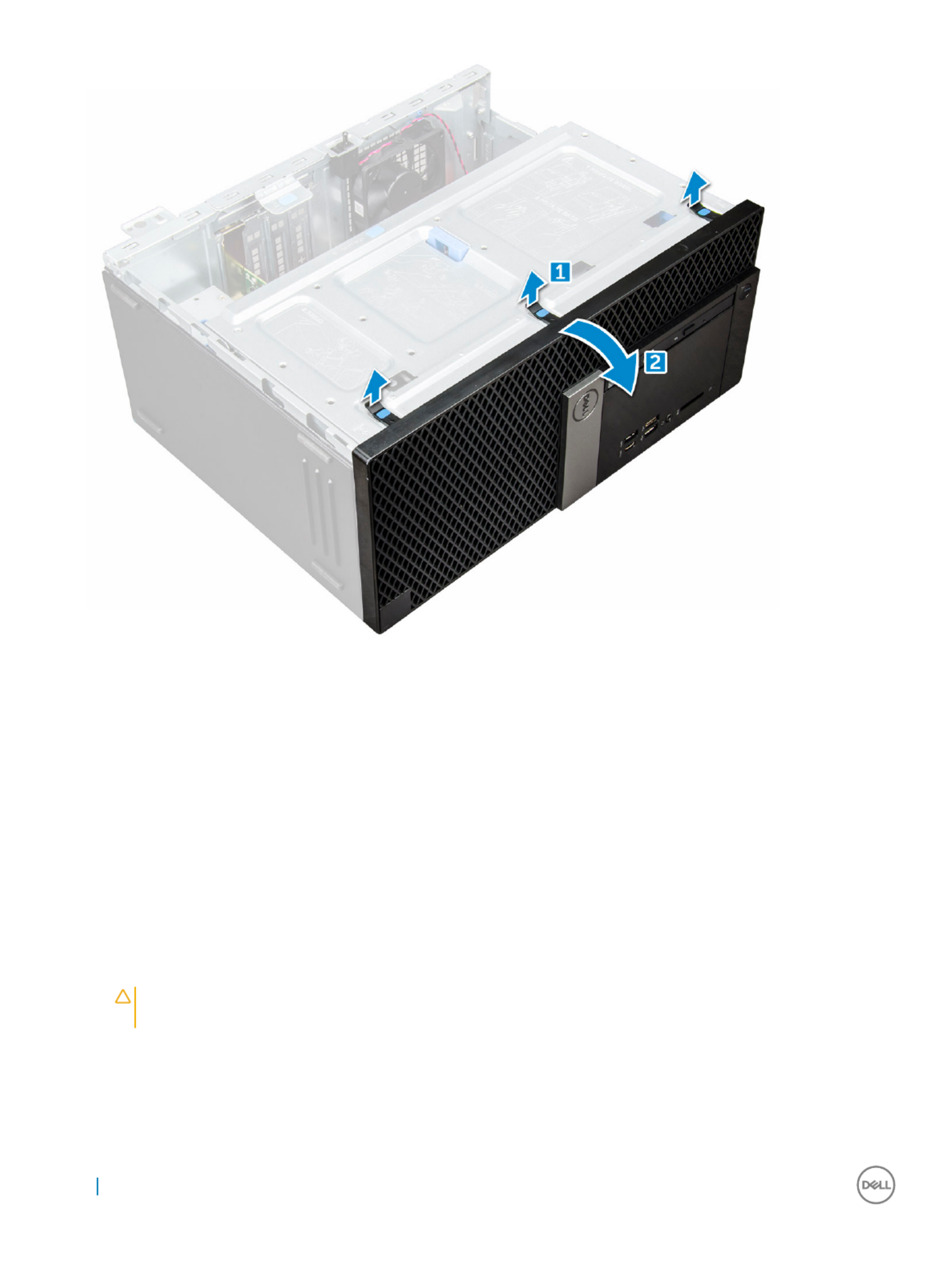
3 To remove the bezel:
a Lift the tabs to release the bezel from the chassis [1].
b Push the bezel away from the chassis [2].
Removing and installing components 11
Installing be
Installing be
Installing be
Installing beInstalling bez
z
z
zzel
el
el
elel
1 Position the bezel to align the tab holders on the chassis.
2 Press the bezel until the tabs click into place.
3 Install the cover.
4 Follow the procedure in After working inside your computer.
Opening the fr
Opening the fr
Opening the fr
Opening the frOpening the fron
on
on
onont panel door
t panel door
t panel door
t panel doort panel door
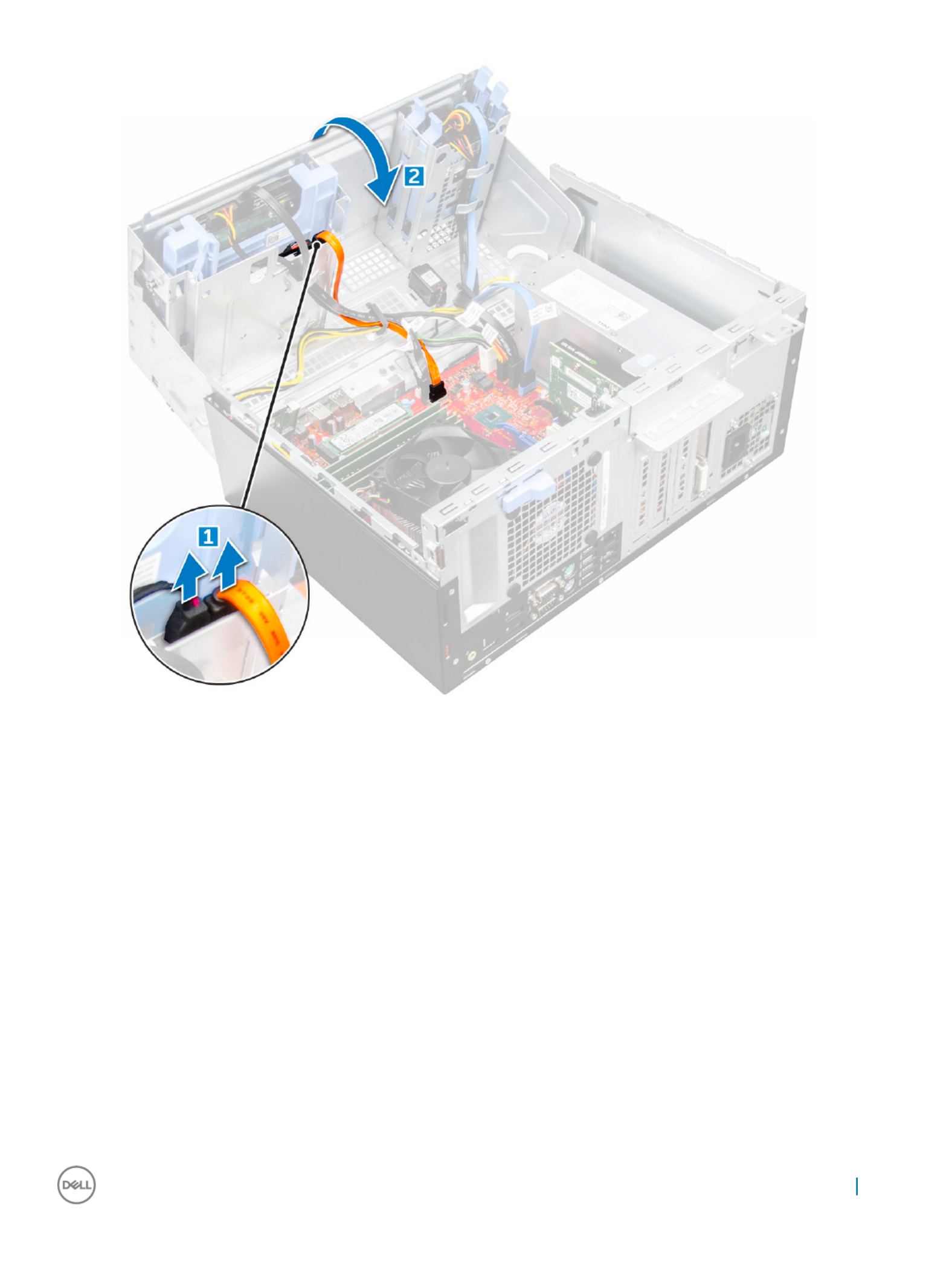
1 Follow the procedure in Before working inside your computer.
2 Remove the:
acover
bbezel
CA
CA
CA
CACAUTION
UTION
UTION
UTIONUTION:
:
:
: : The fr
The fr
The fr
The frThe front panel door opens only t
ont panel door opens only t
ont panel door opens only t
ont panel door opens only tont panel door opens only to a limited e
o a limited e
o a limited e
o a limited eo a limited exten
xten
xten
xtenxtent. See the print
t. See the print
t. See the print
t. See the printt. See the printed image on the fr
ed image on the fr
ed image on the fr
ed image on the fred image on the front panel door f
ont panel door f
ont panel door f
ont panel door font panel door for the
or the
or the
or the or the
maximum permissible lev
maximum permissible lev
maximum permissible lev
maximum permissible levmaximum permissible level.
el.
el.
el.el.
3 Pull the front panel door to open it.
12 Removing and installing components

b Press the blue tab [1] and pull the hard drive assembly out of the computer [ 2].
14 Removing and installing components

Remo
Remo
Remo
RemoRemoving 3
ving 3
ving 3
ving 3ving 3.
.
.
..5–inch har
5–inch har
5–inch har
5–inch har5–inch hard drive fr
d drive fr
d drive fr
d drive frd drive from the har
om the har
om the har
om the harom the hard drive br
d drive br
d drive br
d drive brd drive bracket
acket
acket
acketacket
1 Follow the procedure in Before working inside your computer.
2 Remove the:
acover
bbezel
chard drive assembly
3 To remove the hard drive bracket:
a Pull one side of the hard drive bracket to disengage the pins on the bracket from the slots on the hard drive [1].
b Lift the hard drive out of the hard drive bracket [2].
Removing and installing components 15

Installing 3
Installing 3
Installing 3
Installing 3Installing 3.
.
.
..5–inch har
5–inch har
5–inch har
5–inch har5–inch hard drive assembly
d drive assembly
d drive assembly
d drive assemblyd drive assembly
1 Insert the hard drive assembly into the slot on the computer until it clicks into place.
2 Close the front panel door.
3 Connect the SATA cable and the power cable to the connectors on the hard drive.
4 Install the:
abezel
bcover
5 Follow the procedure in After working inside your computer.
Installing the 3
Installing the 3
Installing the 3
Installing the 3Installing the 3.
.
.
..5–inch har
5–inch har
5–inch har
5–inch har5–inch hard drive in
d drive in
d drive in
d drive ind drive int
t
t
tto the har
o the har
o the har
o the haro the hard drive br
d drive br
d drive br
d drive brd drive bracke
acke
acke
ackeacket
t
t
tt
1 Flex the other side of the hard drive bracket, and align and insert the pins on the bracket into the hard drive.
2 Insert the hard drive into the hard drive bracket until it clicks into place.
3 Install the:
ahard drive assembly
bbezel
ccover
4 Follow the procedure in After working inside your computer.
Remo
Remo
Remo
RemoRemoving the 2.
ving the 2.
ving the 2.
ving the 2.ving the 2.5–inch drive assembly
5–inch drive assembly
5–inch drive assembly
5–inch drive assembly5–inch drive assembly
1 Follow the procedure in Before working inside your computer.
2 Remove the:
acover
bbezel
3 Open the front panel door.
4 To remove the drive assembly:
a Disconnect the drive assembly cables from the connectors on the drive [1].
b Press the blue tabs on both sides [2] and pull the drive assembly out of the computer [3].
16 Removing and installing components

Remo
Remo
Remo
RemoRemoving the 2.
ving the 2.
ving the 2.
ving the 2.ving the 2.5–inch driv
5–inch driv
5–inch driv
5–inch driv5–inch drive fr
e fr
e fr
e fre from the driv
om the driv
om the driv
om the drivom the drive br
e br
e br
e bre bracke
acke
acke
ackeacket
t
t
tt
1 Follow the procedure in Before Working Inside Your Computer.
2 Remove the:
acover
bbezel
c2.5–inch drive assembly
3 To remove the drive:
a Pull one side of the drive bracket to disengage the pins on the bracket from the slots on the drive [1].
b Lift the drive out of the drive bracket [2].
Removing and installing components 17

Installing the 2.
Installing the 2.
Installing the 2.
Installing the 2.Installing the 2.5-inch drive assembly
5-inch drive assembly
5-inch drive assembly
5-inch drive assembly5-inch drive assembly
1 Insert the drive assembly into the slot on the computer until it clicks into place.
2 Close the front panel door.
3 Connect the SATA cable and the power cable to the connectors on the drive.
4 Install the:
•bezel
•cover
5 Follow the procedure in After Working Inside Your Computer.
Optical driv
Optical driv
Optical driv
Optical drivOptical drive
e
e
ee
Remo
Remo
Remo
RemoRemoving optical driv
ving optical driv
ving optical driv
ving optical drivving optical drive
e
e
ee
1 Follow the procedure in Before working inside your computer.
2 Remove the:
acover
bbezel
3 Open the front panel door.
4 To remove the optical drive assembly:
a Disconnect the data cable and power cable from the connectors on the optical drive [1].
NOTE
NOTE
NOTE
NOTENOTE:
:
:
: : Y
Y
Y
YYou may need t
ou may need t
ou may need t
ou may need tou may need to unrout
o unrout
o unrout
o unrouto unroute the cables fr
e the cables fr
e the cables fr
e the cables fre the cables from the tabs under the drive cage t
om the tabs under the drive cage t
om the tabs under the drive cage t
om the tabs under the drive cage tom the tabs under the drive cage to allow you t
o allow you t
o allow you t
o allow you to allow you to disconnect
o disconnect
o disconnect
o disconnect o disconnect
the cables fr
the cables fr
the cables fr
the cables frthe cables from the connector
om the connector
om the connector
om the connectorom the connectors.
s.
s.
s.s.
b Close the front panel door [2].
18 Removing and installing components
c Press the blue release tab [1] and slide the optical drive out of the computer [2].
Removing and installing components 19

Installing op
Installing op
Installing op
Installing opInstalling optical drive
tical drive
tical drive
tical drivetical drive
1 Insert the optical drive into the optical drive bay until it clicks into place.
2 Open the front panel door.
3 Route the data cable and power cable under the drive cage.
4 Connect the data cable and power cable to the connectors on the optical drive.
5 Close the front panel door.
6 Install the:
abezel
bcover
7 Follow the procedure in After working inside your computer.
M.2 PCIe SSD
M.2 PCIe SSD
M.2 PCIe SSD
M.2 PCIe SSD M.2 PCIe SSD
Remo
Remo
Remo
RemoRemoving optional M.2 PCIe SSD
ving optional M.2 PCIe SSD
ving optional M.2 PCIe SSD
ving optional M.2 PCIe SSD ving optional M.2 PCIe SSD
1 Follow the procedure in Before working inside your computer.
2 Remove the:
acover
bbezel
20 Removing and installing components

3 Open the front panel door.
4 To remove the M.2 PCIe SSD:
a Pull the blue tab that secures the M.2 PCIe SSD to the system board [1].
b Disconnect the M.2 PCIe SSD from the connector on the system board [2].
Installing op
Installing op
Installing op
Installing opInstalling optional M.2 PCIe SSD
tional M.2 PCIe SSD
tional M.2 PCIe SSD
tional M.2 PCIe SSD tional M.2 PCIe SSD
1 Insert the M.2 PCIe SSD to the connector.
2 Press the blue tab to secure the M.2 PCIe SSD.
3 Close the front panel door.
4 Install the:
abezel
bcover
5 Follow the procedure in After working inside your computer.
Removing and installing components 21

SD car
SD car
SD car
SD carSD card r
d r
d r
d rd reader
eader
eader
eadereader
Remo
Remo
Remo
RemoRemoving SD car
ving SD car
ving SD car
ving SD carving SD card r
d r
d r
d rd reader
eader
eader
eadereader
1 Follow the procedure in Before working inside your computer.
2 Remove the:
acover
bbezel
3 Open the front panel door.
4 To remove the SD card reader:
a Disconnect the SD card reader cable from the connector on the system board [1].
b Remove the screw that secures the SD card reader to the front panel door [2].
c Lift the SD card reader out of the computer [3].
22 Removing and installing components

Installing SD car
Installing SD car
Installing SD car
Installing SD carInstalling SD card r
d r
d r
d rd reader
eader
eader
eadereader
1 Insert the SD card reader into the slot on the system board.
2 Tighten the screw to secure the SD card reader to the front panel door.
3 Connect the SD card reader cable to the connector on the system board.
4 Close the front panel door.
5 Install the:
abezel
bcover
6 Follow the procedure in After working inside your computer.
Memory module
Memory module
Memory module
Memory moduleMemory module
Remo
Remo
Remo
RemoRemoving memory module
ving memory module
ving memory module
ving memory moduleving memory module
1 Follow the procedure in Before working inside your computer.
2 Remove the:
acover
bbezel
3 Open the front panel door.
4 To remove the memory module:
a Push the memory module retention tabs on both sides of the memory module.
b Lift the memory module from the memory module connector on the system board.
Installing memory module
Installing memory module
Installing memory module
Installing memory moduleInstalling memory module
1 Align the notch on the memory module with the tab on the memory module connector.
2 Insert the memory module into the memory module socket.
3 Press the memory module until the memory module retention tabs click into place.
4 Close the front panel door.
5 Install the:
acover
bbezel
6 Follow the procedure in After working inside your computer.
Removing and installing components 23

Expansion car
Expansion car
Expansion car
Expansion carExpansion card
d
d
dd
Remo
Remo
Remo
RemoRemoving PCIe expansion car
ving PCIe expansion car
ving PCIe expansion car
ving PCIe expansion carving PCIe expansion card
d
d
dd
1 Follow the procedure in Before working inside your computer.
2 Remove the:
acover
bbezel
3 Open the front panel door.
4 To remove the PCIe expansion card:
a Pull the release latch to unlock the PCIe expansion card [1].
b Push the card retention latch [2], and lift the PCIe expansion card out of the computer [3].
NOTE:
NOTE:
NOTE:
NOTE: NOTE: This st
This st
This st
This stThis step is applicable only for the connect
ep is applicable only for the connect
ep is applicable only for the connect
ep is applicable only for the connectep is applicable only for the connector with card r
or with card r
or with card r
or with card ror with card reten
eten
eten
etenetention latch, o
tion latch, o
tion latch, o
tion latch, otion latch, otherwise, lift the PCIe
therwise, lift the PCIe
therwise, lift the PCIe
therwise, lift the PCIe therwise, lift the PCIe
expansion car
expansion car
expansion car
expansion carexpansion card out of the comput
d out of the comput
d out of the comput
d out of the computd out of the computer
er
er
erer.
.
.
..
5 Repeat the steps to remove any additional PCIe expansion card.
24 Removing and installing components

Installing PCIe e
Installing PCIe e
Installing PCIe e
Installing PCIe eInstalling PCIe expansion car
xpansion car
xpansion car
xpansion carxpansion card
d
d
dd
1 Pull the release latch backward to open [1].
2 To remove the PCIe brackets (1 and 3) as shown below, insert a screwdriver in the hole of a PCIe bracket and push hard to release the
bracket [2], and then lift the bracket out from your computer.
NOTE:
NOTE:
NOTE:
NOTE: NOTE: T
T
T
TT
o r
o r
o r
o ro remove the PCIe br
emove the PCIe br
emove the PCIe br
emove the PCIe bremove the PCIe bracket
acket
acket
acketackets (2 and 4), push the brack
s (2 and 4), push the brack
s (2 and 4), push the brack
s (2 and 4), push the bracks (2 and 4), push the bracket upwar
et upwar
et upwar
et upwaret upwards fr
ds fr
ds fr
ds frds from the inside of your comput
om the inside of your comput
om the inside of your comput
om the inside of your computom the inside of your computer to r
er to r
er to r
er to rer to release it
elease it
elease it
elease it elease it
and then lift the brack
and then lift the brack
and then lift the brack
and then lift the brackand then lift the bracket aw
et aw
et aw
et awet away fr
ay fr
ay fr
ay fray from your computer
om your computer
om your computer
om your computerom your computer.
.
.
..
3 Insert the PCIe expansion card to the connector on the system board.
4 Secure the PCIe expansion card by pushing the card retention latch until it clicks into place.
5 Repeat the steps to install any additional PCIe expansion card.
6 Close the release latch.
7 Close the front panel door.
8 Install the:
abezel
bcover
Removing and installing components 25

9 Follow the procedure in After working inside your computer.
P
P
P
PPow
ow
ow
owower supply unit
er supply unit
er supply unit
er supply uniter supply unit
Remo
Remo
Remo
RemoRemoving pow
ving pow
ving pow
ving powving power supply unit (PSU)
er supply unit (PSU)
er supply unit (PSU)
er supply unit (PSU)er supply unit (PSU)
1 Follow the procedure in Before working inside your computer.
2 Remove the:
acover
bbezel
3 Open the .front panel door
4 To release the PSU:
a Disconnect the PSU cables from the connectors on the system board [1] [2].
b Pull the release clip [3].
c Unroute the PSU cables from the retention clip [4].
d Remove the screws that secure the PSU to the computer [5].
5 To remove the PSU:
a Press the release tab [1].
b Slide and lift the PSU away from the computer [2].
26 Removing and installing components

Installing po
Installing po
Installing po
Installing poInstalling power supply unit (PSU
wer supply unit (PSU
wer supply unit (PSU
wer supply unit (PSUwer supply unit (PSU)
)
)
))
1 Insert the PSU into the PSU slot and slide it toward the back of the computer until it clicks into place.
2 Tighten the screws to secure the PSU to the computer.
3 Route the PSU cables through the retention clips.
4 Connect the PSU cables to the connectors on the system board.
5 Close the front panel door.
6 Install the:
abezel
bcover
7 Follow the procedure in After working inside your computer.
Removing and installing components 27

VGA daugh
VGA daugh
VGA daugh
VGA daughVGA daught
t
t
tter boar
er boar
er boar
er boarer board
d
d
dd
Remo
Remo
Remo
RemoRemoving VGA daugh
ving VGA daugh
ving VGA daugh
ving VGA daughving VGA daught
t
t
tter boar
er boar
er boar
er boarer board
d
d
dd
1 Follow the procedure in Before working inside your computer.
2 Remove the:
acover
bbezel
3 Open the front panel door
4 To remove the VGA daughter board:
a Remove the screws that secure the VGA connector to the computer [1].
b Slide the VGA connector to release it from the computer.
c Remove the screw that secures the VGA daughter board to the computer [2].
d Lift the VGA daughter board using the handle to remove it from the computer [3].
28 Removing and installing components

Installing V
Installing V
Installing V
Installing VInstalling VGA daught
GA daught
GA daught
GA daughtGA daughter boar
er boar
er boar
er boarer board
d
d
dd
1 Align the VGA daughter board with the screw holder on the system board.
2 Tighten the screw to secure the VGA daughter board to the system board.
3 Insert the VGA connector into the slot at the back of the computer.
4 Tighten the screws to secure the VGA connector to the computer.
5 Close the front panel door.
6 Install the:
abezel
bcover
7 Follow the procedure in After working inside your computer.
Intrusion s
Intrusion s
Intrusion s
Intrusion sIntrusion swit
wit
wit
witwitch
ch
ch
chch
Remo
Remo
Remo
RemoRemoving intrusion s
ving intrusion s
ving intrusion s
ving intrusion sving intrusion swit
wit
wit
witwitch
ch
ch
chch
1 Follow the procedure in Before working inside your computer.
2 Remove the:
acover
bbezel
3 Open the front panel door.
4 To remove the intrusion switch:
a Disconnect the intrusion switch cable from the connector on the system board [1] [2].
b Unroute the intrusion switch cable from the fan grommet.
c Slide the intrusion switch and push it to remove from the computer [3].
Removing and installing components 29

acover
bbezel
3 Open the front panel door.
4 To release the power switch:
a Disconnect the power switch cable from the system board [1].
b Unroute the power switch cable through the retention clip [2].
c Press the release tabs using a plastic scribe and slide the power switch out from the front of the computer [2,3].
d Close the front panel door [4].
5 Pull the power switch out from the computer.
Removing and installing components 31
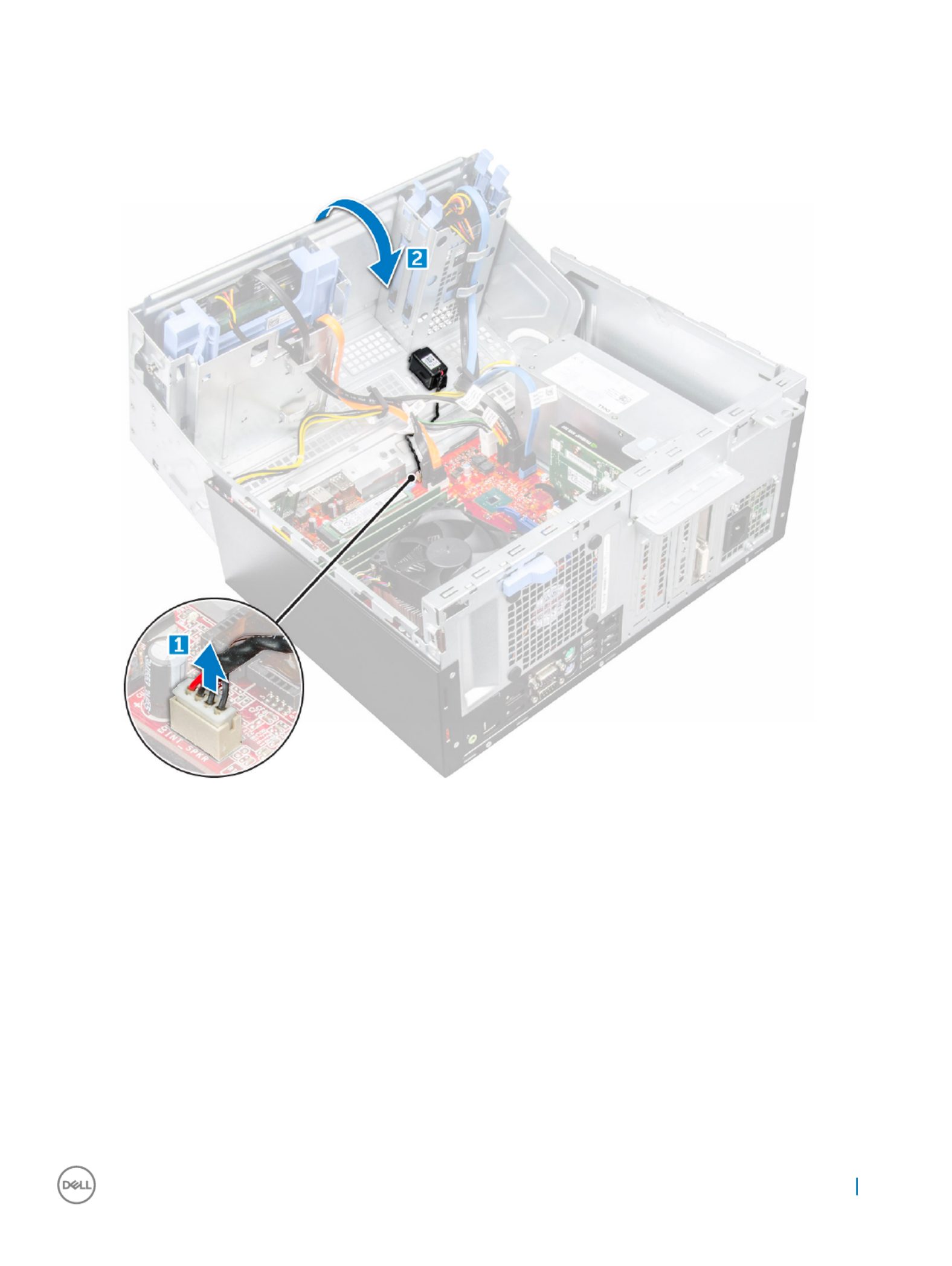
3 Open the front panel door.
4 To remove the speaker:
a Disconnect the speaker cable from the connector on the system board [1].
b Close the front panel door.
c Press the release tabs [1], and slide the speaker [2] out of the slot.
Removing and installing components 33

Installing speak
Installing speak
Installing speak
Installing speakInstalling speaker
er
er
erer
1 Insert the speaker into the slot and press it until it clicks into place.
2 Connect the speaker cable to the connector on the system board.
3 Close the front panel door.
4 Install the:
abezel
bcover
5 Follow the procedure in After working inside your computer.
Coin cell bat
Coin cell bat
Coin cell bat
Coin cell batCoin cell batt
t
t
ttery
ery
ery
eryery
Remo
Remo
Remo
RemoRemoving coin cell bat
ving coin cell bat
ving coin cell bat
ving coin cell batving coin cell batt
t
t
ttery
ery
ery
eryery
1 Follow the procedure in Before working inside your computer.
2 Remove the:
acover
bbezel
3 Open the front panel door.
34 Removing and installing components

4 To remove the coin cell battery:
a Press the release latch until the coin cell battery pops out [1].
b Remove the coin cell battery from the connector on the system board [2].
Installing the coin cell ba
Installing the coin cell ba
Installing the coin cell ba
Installing the coin cell baInstalling the coin cell bat
t
t
ttt
t
t
ttery
ery
ery
eryery
1 Hold the coin cell battery with the "+" sign facing up and slide it under the securing tabs at the positive side of the connector.
2 Press the battery into the connector until it locks into place.
3 Close the front panel door.
4 Install the:
•bezel
•cover
5 Follow the procedure in After working inside your computer.
Removing and installing components 35
Product specificaties
| Merk: | Dell |
| Categorie: | Desktop |
| Model: | OptiPlex 7050 |
| Kleur van het product: | Zwart |
| Gewicht: | 5140 g |
| Breedte: | 92.71 mm |
| Diepte: | 292.1 mm |
| Hoogte: | 290.06 mm |
| Gebruikershandleiding: | Ja |
| Frequentie van processor: | 3.4 GHz |
| Processorfamilie: | Intel® Core™ i5 |
| Processormodel: | i5-7500 |
| Aantal processorkernen: | 4 |
| Inclusief besturingssysteem: | Windows 10 Pro |
| Ondersteuning voor plaatsing: | Horizontaal/Verticaal |
| Ethernet LAN: | Ja |
| Meegeleverde kabels: | AC |
| Geïntegreerde geheugenkaartlezer: | Nee |
| Processor lithografie: | 14 nm |
| Aantal USB 2.0-poorten: | 4 |
| Aantal HDMI-poorten: | 1 |
| Microfoon, line-in ingang: | Nee |
| DVI-poort: | Nee |
| Aantal Ethernet LAN (RJ-45)-poorten: | 1 |
| Wachtwoordbeveiliging: | Ja |
| Netvoeding: | 180 W |
| Intern geheugen: | 4 GB |
| Opslagmedia: | HDD |
| Intern geheugentype: | DDR4-SDRAM |
| Password bescherming: | BIOS, Supervisor, User |
| Aantal DisplayPorts: | 2 |
| Ethernet LAN, data-overdrachtsnelheden: | 10,100,1000 Mbit/s |
| Bekabelingstechnologie: | 10/100/1000Base-T(X) |
| Temperatuur bij opslag: | -40 - 65 °C |
| Aantal poorten USB 3.2 Gen 1 (3.1 Gen 1) Type A: | 5 |
| Processor socket: | LGA 1151 (Socket H4) |
| Stepping: | B0 |
| Systeembus: | 8 GT/s |
| Processor aantal threads: | 4 |
| PCI Express slots versie: | 3.0 |
| Processor operating modes: | 64-bit |
| Processor cache: | 6 MB |
| Tjunction: | 100 °C |
| Bus type: | DMI3 |
| PCI Express configuraties: | 1x16, 1x8+2x4, 2x8 |
| Thermal Design Power (TDP): | 65 W |
| Codenaam processor: | Kaby Lake |
| Maximaal aantal PCI Express-lijnen: | 16 |
| Processor cache type: | Smart Cache |
| ECC ondersteund door processor: | Nee |
| Processorfabrikant: | Intel |
| Architectuur besturingssysteem: | 64-bit |
| Trial-software: | Microsoft Office |
| Maximum intern geheugen: | 64 GB |
| Totale opslagcapaciteit: | 500 GB |
| Soort optische drive: | DVD±RW |
| Ingebouwde grafische adapter: | Ja |
| Aparte grafische adapter: | Nee |
| On-board graphics adapter model: | Intel® HD Graphics 630 |
| Basisfrequentie ingebouwde grafische adapter: | 350 MHz |
| Graphics on-board -adapter dynamische frequentie (max): | 1100 MHz |
| On-board grafische adapter ID: | 5912 |
| Maximaal geheugen ingebouwde grafische adapter: | 64 GB |
| On-board grafische adapter DirectX-versie: | 12.0 |
| On-board grafische adapter OpenGL versie: | 4.4 |
| Ondersteunde instructie sets: | AVX 2.0, SSE4.1, SSE4.2 |
| Intel® Hyper Threading Technology (Intel® HT Technology): | Nee |
| Intel® Turbo Boost Technology: | 2.0 |
| Intel® Quick Sync Video Technology: | Ja |
| Intel® InTru™ 3D Technology: | Ja |
| Intel® Clear Video HD Technology (Intel® CVT HD): | Ja |
| Intel® AES New Instructions (Intel® AES-NI): | Ja |
| Enhanced Intel SpeedStep Technology: | Ja |
| Execute Disable Bit: | Ja |
| Idle States: | Ja |
| Thermal Monitoring Technologies: | Ja |
| CPU configuratie (max): | 1 |
| Intel® Enhanced Halt State: | Ja |
| Intel® Clear Video Technology for Mobile Internet Devices (Intel® CVT for MID): | Ja |
| Intel® VT-x with Extended Page Tables (EPT): | Ja |
| Ingebouwde opties beschikbaar: | Ja |
| Intel® Secure Key: | Ja |
| Intel® 64: | Ja |
| Intel® OS Guard: | Ja |
| Intel® Virtualization Technology for Directed I/O (VT-d): | Ja |
| Intel® Clear Video-technologie: | Ja |
| Intel® Software Guard Extensions (Intel® SGX): | Ja |
| Intel® Virtualization Technology (VT-x): | Ja |
| Verpakkingsgrootte processor: | 37.5 x 37.5 mm |
| Conflictvrije processor: | Ja |
| Intel® Identity Protection Technology (Intel® IPT): | Ja |
| Versie Intel® Identity Protection Technology: | 1.00 |
| Versie Intel® Secure Key Technology: | 1.00 |
| ARK ID processor: | 97123 |
| Intel® Trusted Execution Technology: | Ja |
| Intel® TSX-NI: | Ja |
| Intel® Stable Image Platform Program (SIPP): | Ja |
| Versie Intel® Stable Image Platform Program (SIPP): | 1.00 |
| Versie Intel® TSX-NI: | 1.00 |
| Toetsenbord inbegrepen: | Ja |
| Combo koptelefoon/microfoon port: | Ja |
| Luchtvochtigheid bij opslag: | 5 - 95 procent |
| Maximale turbofrequentie van processor: | 3.8 GHz |
| Processorcode: | SR335 |
| Discreet grafische adapter model: | Niet beschikbaar |
| Aantal poortenUSB 3.2 Gen 1 (3.1 Gen 1) Type C: | 1 |
| Inclusief muis: | Ja |
| Type behuizing: | SFF |
| Maximaal intern geheugen ondersteund door processor: | 64 GB |
| Geheugentypen ondersteund door processor: | DDR3L-SDRAM, DDR4-SDRAM |
| Klokgeheugen-snelheden ondersteund door processor: | 1333,1600,2133,2400 MHz |
| Kloksnelheid geheugen: | 2400 MHz |
| Geheugenlayout: | 1 x 4 GB |
| Geheugenslots: | 4x DIMM |
| Aantal displays ondersteund (door on-board grafische adapter): | 3 |
| Aantal geïnstalleerde processoren: | 1 |
| Aantal storage drives geïnstalleerd: | 1 |
| Lijnuitgang: | Ja |
| Inclusief monitor: | Nee |
| Schaalbaarheid: | 1S |
| Thermal solution specificatie: | PCG 2015C |
| Hoogte, in bedrijf: | -15.2 - 3048 m |
| Hoogte bij opslag: | -15.2 - 10668 m |
| Het aantal geïnstalleerde HDD's: | 1 |
| HDD capaciteit: | 500 GB |
| HDD interface: | SATA |
| HDD rotatiesnelheid: | 7200 RPM |
| Trusted Platform Module (TPM): | Ja |
| Audiochip: | Realtek ALC3234 |
| Meegeleverde drivers: | Ja |
| PCI Express x16 slots: | 1 |
| Optische drives hoeveelheid: | 1 |
| Processorserie: | Intel Core i5-7500 Desktop Series |
| Geheugen kanaal: | Dubbelkanaals |
| HDD omvang: | 3.5 " |
| PS/2 poort(en): | 2 |
| Seriële poort(en): | 1 |
| PCI Express x4 slots: | 1 |
| Voeding, voltage ingang: | 90 - 264 V |
| Wifi: | Nee |
| Bedrijfstemperatuur (T-T): | 0 - 35 °C |
| Relatieve vochtigheid in bedrijf (V-V): | 10 - 90 procent |
| Type product: | PC |
| Ingangsfrequentie voeding: | 47/63 Hz |
| Voltage geheugen ondersteund door processor: | 1.35 V |
| Processorgeneratie: | Zevende generatie Intel® Core™ i5 |
Heb je hulp nodig?
Als je hulp nodig hebt met Dell OptiPlex 7050 stel dan hieronder een vraag en andere gebruikers zullen je antwoorden
Handleiding Desktop Dell

8 Juli 2024
10 Juni 2024
28 Mei 2024
6 December 2023
29 November 2023
29 November 2023
29 November 2023
29 November 2023
29 November 2023
29 November 2023
Handleiding Desktop
- Desktop HP
- Desktop Sony
- Desktop Samsung
- Desktop LG
- Desktop Asus
- Desktop Medion
- Desktop Toshiba
- Desktop VTech
- Desktop Acer
- Desktop Alienware
- Desktop AOC
- Desktop AOpen
- Desktop Apple
- Desktop Asrock
- Desktop Axis
- Desktop BenQ
- Desktop Emachines
- Desktop Faytech
- Desktop Fujitsu
- Desktop Gigabyte
- Desktop Haier
- Desktop Ibm
- Desktop InFocus
- Desktop Kobo
- Desktop Kogan
- Desktop Lenovo
- Desktop Maxdata
- Desktop Microsoft
- Desktop Mio
- Desktop MP
- Desktop MSI
- Desktop Nec
- Desktop Packard Bell
- Desktop Peaq
- Desktop Razer
- Desktop Seagate
- Desktop Sharkoon
- Desktop Sharp
- Desktop Targa
- Desktop Trekstor
- Desktop Viewsonic
- Desktop Wehkamp
- Desktop Woood
- Desktop ZTE
- Desktop Jysk
- Desktop ONYX
- Desktop Optoma
- Desktop Parisot
- Desktop Intel
- Desktop BDI
- Desktop Tripp Lite
- Desktop LC-Power
- Desktop Zoostorm
- Desktop ZOTAC
- Desktop Planar
- Desktop Supermicro
- Desktop ELO
- Desktop Shuttle
- Desktop VXL
- Desktop ECS
- Desktop Vorago
- Desktop Promethean
- Desktop Foxconn
- Desktop Advantech
- Desktop Moxa
- Desktop Kramer
- Desktop Elitegroup
- Desktop Smart Things
- Desktop System76
- Desktop Bestar
- Desktop Pelco
- Desktop Cybernet
- Desktop Altra
- Desktop Dell Wyse
- Desktop NComputing
- Desktop MvixUSA
- Desktop AIS
- Desktop Wyse
- Desktop Kendall Howard
Nieuwste handleidingen voor Desktop

9 April 2025

1 April 2025
1 April 2025

28 Maart 2025
27 Maart 2025

25 Februari 2025
25 Februari 2025
25 Februari 2025
24 Februari 2025
10 Februari 2025