Dell Latitude 3160 Handleiding
Lees hieronder de 📖 handleiding in het Nederlandse voor Dell Latitude 3160 (51 pagina's) in de categorie Laptop. Deze handleiding was nuttig voor 42 personen en werd door 2 gebruikers gemiddeld met 4.5 sterren beoordeeld
Pagina 1/51

Dell Latitude 3160
Owner's Manual
Regulatory Model: P21T
Regulatory Type: P21T002

Notes, cautions, and warnings
NOTE:
NOTE:
NOTE:
NOTE: NOTE: A NOTE indicates important information that helps you make better use of your computer.
CAUTION: A CAUTION indicates either potential damage to hardware or loss of data and tells you
how to avoid the problem.
WARNING: A WARNING indicates a potential for property damage, personal injury, or death.
Copyright, 2009 – 2015 Dell Inc. All rights reserved. This product is protected by U.S. and international copyright and
intellectual property laws. Dell™ and the Dell logo are trademarks of Dell Inc. in the United States and/or other
jurisdictions. All other marks and names mentioned herein may be trademarks of their respective companies.
2015 - 05
Rev. A00

Contents
1 Working on Your Computer................................................................................5
Before Working Inside Your Computer................................................................................................ 5
Turning Off Your Computer..................................................................................................................6
After Working Inside Your Computer................................................................................................... 7
2 Removing and Installing Components............................................................. 8
Recommended Tools............................................................................................................................8
Removing the Base Cover.....................................................................................................................8
Installing the Base Cover.......................................................................................................................9
Removing the Battery............................................................................................................................9
Installing the Battery............................................................................................................................10
Removing the Audio Board.................................................................................................................10
Installing the Audio Board....................................................................................................................11
Removing the WLAN Card...................................................................................................................11
Installing the WLAN Card.................................................................................................................... 12
Removing the Display Assembly......................................................................................................... 12
Installing the Display Assembly...........................................................................................................14
Removing the Display Bezel................................................................................................................14
Installing the Display Bezel..................................................................................................................15
Removing the Display Panel............................................................................................................... 16
Installing the Display Panel..................................................................................................................17
Removing the Camera........................................................................................................................ 18
Installing the Camera.......................................................................................................................... 18
Removing the Power-Connector Port............................................................................................... 19
Installing the Power-Connector Port................................................................................................. 19
Removing the Hard-Drive Assembly.................................................................................................. 19
Installing the Hard-Drive Assembly.................................................................................................... 21
Removing the LED Board....................................................................................................................22
Installing the LED Board......................................................................................................................22
Removing the Memory....................................................................................................................... 23
Installing the Memory......................................................................................................................... 23
Removing the Coin-Cell Battery........................................................................................................ 23
Installing the Coin-Cell Battery.......................................................................................................... 24
Removing the Keyboard Trim.............................................................................................................24
Installing the Keyboard Trim...............................................................................................................25
Removing the Keyboard......................................................................................................................25
Installing the Keyboard........................................................................................................................27
Removing the Heatsink....................................................................................................................... 27
3

Installing the Heatsink.........................................................................................................................28
Removing the System Board.............................................................................................................. 29
Installing the System Board................................................................................................................ 30
Removing the Speaker........................................................................................................................30
Installing the Speaker.......................................................................................................................... 31
3 System Setup....................................................................................................... 32
Boot Sequence.................................................................................................................................... 32
Navigation Keys................................................................................................................................... 32
System Setup Options.........................................................................................................................33
Updating the BIOS ............................................................................................................................. 40
System and Setup Password............................................................................................................... 41
Assigning a System Password and Setup Password.....................................................................41
Deleting or Changing an Existing System and/or Setup Password.............................................42
4 Technical Specifications................................................................................... 43
5 Diagnostics.......................................................................................................... 48
Enhanced Pre-Boot System Assessment (ePSA) Diagnostics........................................................... 48
Device Status Lights............................................................................................................................49
Battery Status Lights............................................................................................................................50
6 Contacting Dell................................................................................................... 51
4

1
Working on Your Computer
Before Working Inside Your Computer
Use the following safety guidelines to help protect your computer from potential damage and to help to
ensure your personal safety. Unless otherwise noted, each procedure included in this document assumes
that the following conditions exist:
• You have read the safety information that shipped with your computer.
• A component can be replaced or--if purchased separately--installed by performing the removal
procedure in reverse order.
WARNING: Disconnect all power sources before opening the computer cover or panels. After you
finish working inside the computer, replace all covers, panels, and screws before connecting to
the power source.
WARNING: Before working inside your computer, read the safety information that shipped with
your computer. For additional safety best practices information, see the Regulatory Compliance
Homepage at www.dell.com/regulatory_compliance
CAUTION: Many repairs may only be done by a certified service technician. You should only
perform troubleshooting and simple repairs as authorized in your product documentation, or as
directed by the online or telephone service and support team. Damage due to servicing that is
not authorized by Dell is not covered by your warranty. Read and follow the safety instructions
that came with the product.
CAUTION: To avoid electrostatic discharge, ground yourself by using a wrist grounding strap or
by periodically touching an unpainted metal surface, such as a connector on the back of the
computer.
CAUTION: Handle components and cards with care. Do not touch the components or contacts
on a card. Hold a card by its edges or by its metal mounting bracket. Hold a component such as a
processor by its edges, not by its pins.
CAUTION: When you disconnect a cable, pull on its connector or on its pull-tab, not on the cable
itself. Some cables have connectors with locking tabs; if you are disconnecting this type of cable,
press in on the locking tabs before you disconnect the cable. As you pull connectors apart, keep
them evenly aligned to avoid bending any connector pins. Also, before you connect a cable,
ensure that both connectors are correctly oriented and aligned.
NOTE:
NOTE:
NOTE:
NOTE: NOTE: The color of your computer and certain components may appear differently than shown in
this document.
5

To avoid damaging your computer, perform the following steps before you begin working inside the
computer.
1. Ensure that your work surface is flat and clean to prevent the computer cover from being scratched.
2. Turn off your computer (see ).Turning off Your Computer
3. If the computer is connected to a docking device (docked), undock it.
CAUTION: To disconnect a network cable, first unplug the cable from your computer and
then unplug the cable from the network device.
4. Disconnect all network cables from the computer.
5. Disconnect your computer and all attached devices from their electrical outlets.
6. Close the display and turn the computer upside-down on a flat work surface.
NOTE:
NOTE:
NOTE:
NOTE: NOTE: To avoid damaging the system board, you must remove the main battery before you
service the computer.
7. Remove the base cover.
8. Remove the main battery.
9. Turn the computer top-side up.
10. Open the display.
11. Press and hold the power button for few seconds, to ground the system board.
CAUTION: To guard against electrical shock, always unplug your computer from the
electrical outlet before opening the display.
CAUTION: Before touching anything inside your computer, ground yourself by touching an
unpainted metal surface, such as the metal at the back of the computer. While you work,
periodically touch an unpainted metal surface to dissipate static electricity, which could
harm internal components.
12. Remove any installed ExpressCards or Smart Cards from the appropriate slots.
Turning Off Your Computer
CAUTION: To avoid losing data, save and close all open files and exit all open programs before
you turn off your computer.
1. Shut down the operating system:
• In Windows 8.1:
– Using a touch-enabled device:
a. Swipe in from the right edge of the screen, opening the Charms menu and select
Settings.
b. Select the and then select .Shut down
Or
* On the Home screen, touch the and then select .Shut down
– Using a mouse:
6

a. Point to upper-right corner of the screen and click . Settings
b. Click the and select .Shut down
Or
* On the Home screen, click and then select .Shut down
• In Windows 7:
1. Click .Start
2. Click Shut Down.
or
1. Click .Start
2. Click the arrow in the lower-right corner of the menu as shown below, and then click Start
Shut Down .
2. Ensure that the computer and all attached devices are turned off. If your computer and attached
devices did not automatically turn off when you shut down your operating system, press and hold
the power button for about 6 seconds to turn them off.
After Working Inside Your Computer
After you complete any replacement procedure, ensure you connect any external devices, cards, and
cables before turning on your computer.
CAUTION: To avoid damage to the computer, use only the battery designed for this particular
Dell computer. Do not use batteries designed for other Dell computers.
1. Connect any external devices, such as a port replicator or media base, and replace any cards, such as
an ExpressCard.
2. Connect any telephone or network cables to your computer.
CAUTION: To connect a network cable, first plug the cable into the network device and then
plug it into the computer.
3. Replace the battery.
4. Replace the base cover.
5. Connect your computer and all attached devices to their electrical outlets.
6. Turn on your computer.
7

2
Removing and Installing Components
This section provides detailed information on how to remove or install the components from your
computer.
Recommended Tools
The procedures in this document may require the following tools:
• Small flat-blade screwdriver
• #0 Phillips screwdriver
• #1 Phillips screwdriver
• Small plastic scribe
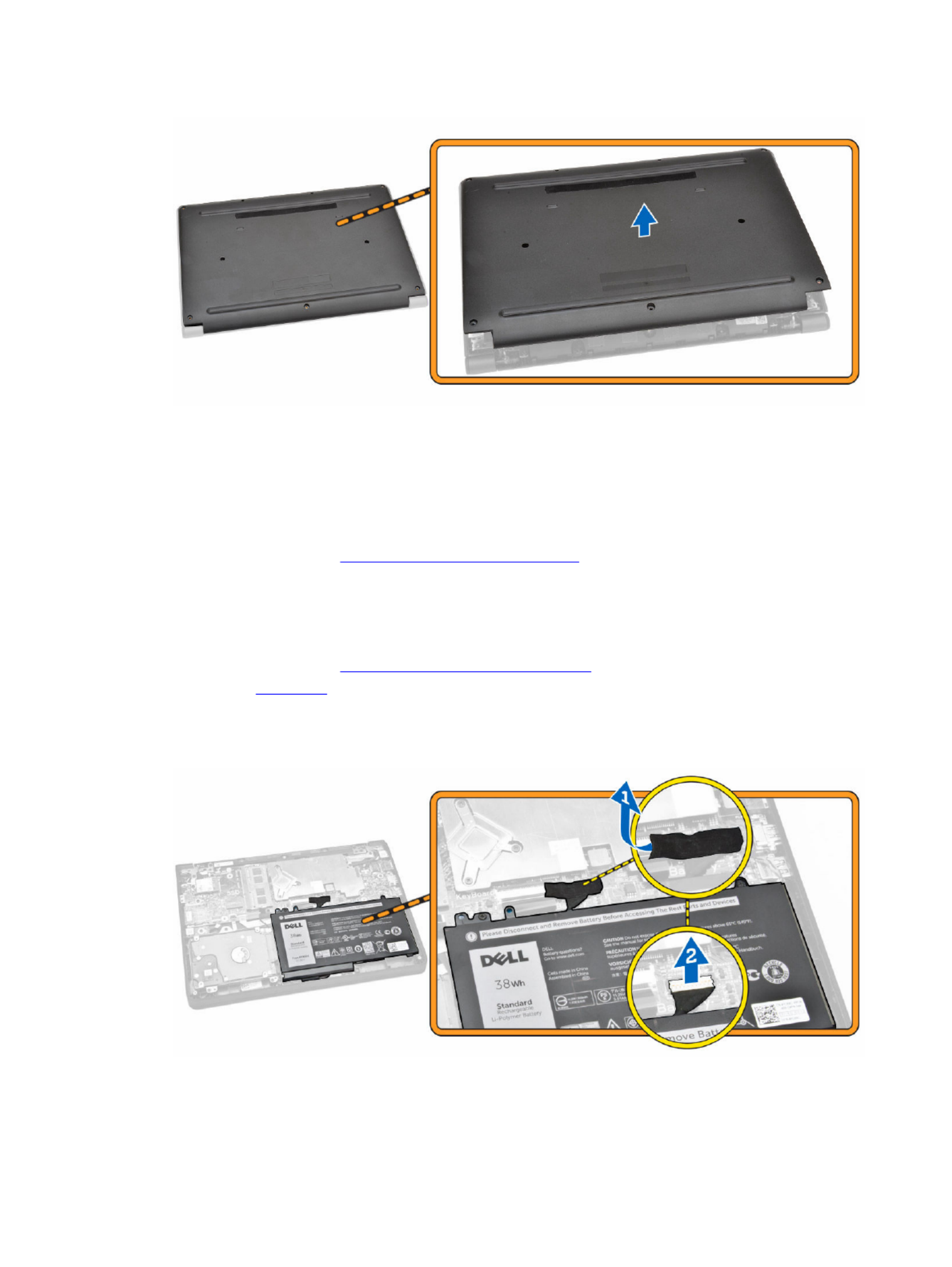
Removing the Base Cover
1. Follow the procedures in .Before Working Inside Your Computer
2. Perform the following steps to remove the base cover from the computer:
a. Remove the screws that secure the base cover to the computer.
b. Pry the base cover to release it from the computer.
NOTE:
NOTE:
NOTE:
NOTE: NOTE: You may need a sharp tool to pry the base cover around the edges.
3. Remove the base cover from the computer.
8
Installing the Base Cover
1. Place the base cover to align with the screw holders on the computer.
2. Tighten the screws to secure the base cover to the computer.
3. Follow the procedures in .After Working Inside Your Computer
Removing the Battery
1. Follow the procedures in .Before Working Inside Your Computer
2. Remove the .base cover
3. To release the battery from the computer:
a. Peel the adhesive tape that secures the battery cable [1].
b. Disconnect the battery cable from its connector on the system board [2].
4. Perform the following steps:
9
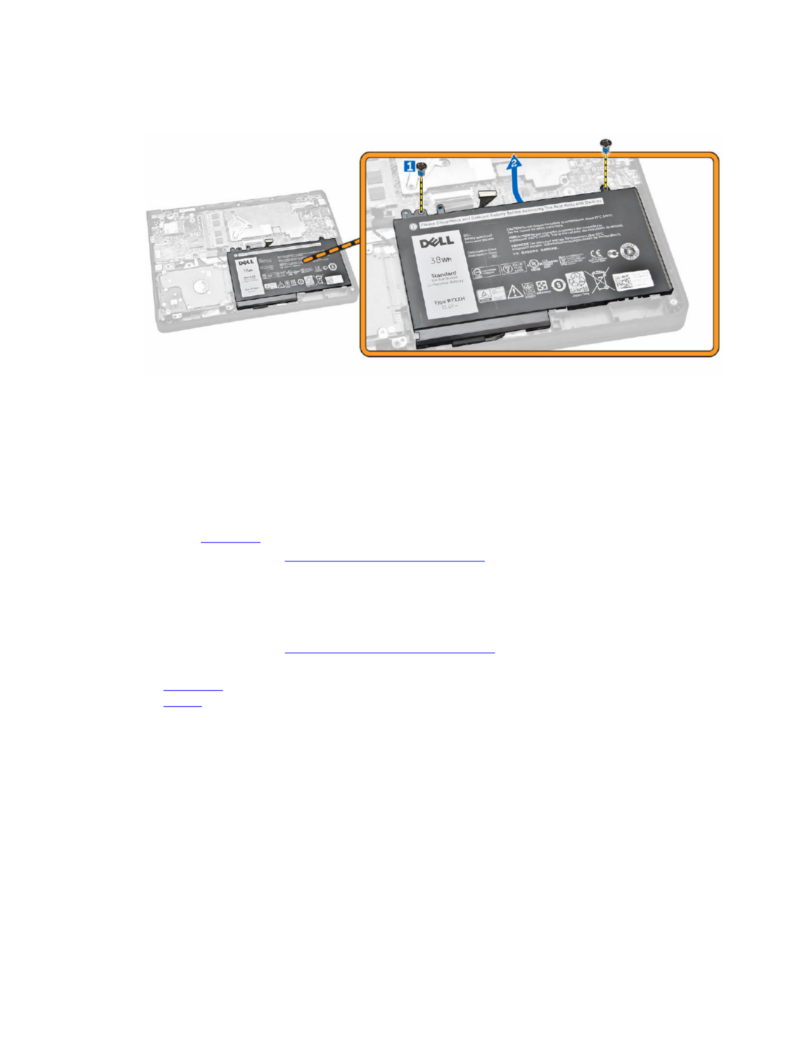
a. Remove the screws that secure the battery to the computer [1].
b. Remove the battery from the computer [2].
Installing the Battery
1. Insert the battery into its place on the computer.
2. Connect the battery cable to its connector on the system board.
3. Fix the adhesive tape to secure the battery cable.
4. Tighten the screws to secure the battery to the computer.
5. Install the .base cover
6. Follow the procedures in .After Working Inside Your Computer
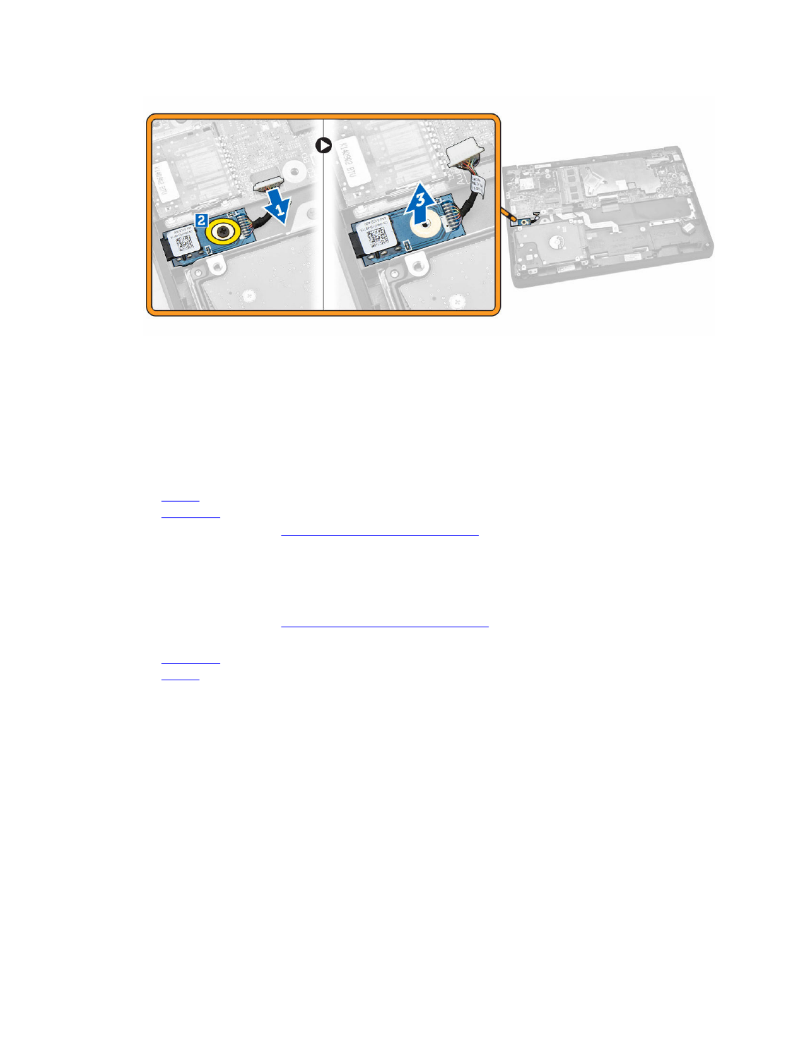
Removing the Audio Board
1. Follow the procedures in .Before Working Inside Your Computer
2. Remove the:
a. base cover
b. battery
3. Perform the following steps:
a. Disconnect the audio-board cable from its connector on the system board [1].
b. Remove the screw that secures the audio board to the computer [2].
c. Remove the audio board from the computer [3].
10
Installing the Audio Board
1. Insert the audio board into its place on the computer.
2. Tighten the screw to secure the audio board to the computer.
3. Connect the audio-board cable to its connector on the system board.
4. Install the:
a. battery
b. base cover
5. Follow the procedures in .After Working Inside Your Computer
Removing the WLAN Card
1. Follow the procedures in .Before Working Inside Your Computer
2. Remove the:
a. base cover
b. battery
3. Perform the following steps:
a. Remove the screw that secures the metal bracket to the WLAN card [1].
b. Remove the metal bracket to access the WLAN cables [2].
c. Disconnect the WLAN cables from their connectors on the WLAN card [3].
d. Remove the WLAN card from its connector on the system board [4].
11

Installing the WLAN Card
1. Insert the WLAN card to its connector on the system board.
2. Connect the WLAN cables to their connectors on the WLAN card.
3. Insert the metal bracket to secure the WLAN cables.
4. Tighten the screw to secure the WLAN card to the system board.
5. Install the:
a. battery
b. base cover
6. Follow the procedures in .After Working Inside Your Computer
Removing the Display Assembly
1. Follow the procedures in .Before Working Inside Your Computer
2. Remove the:
a. base cover
b. battery
c. WLAN
3. To release the display assembly from the computer:
a. Disconnect the network cable from its connector on the system board [1].
b. Remove the screws that secure the metal bracket to the system board [2].
c. Remove the metal bracket to access the display cable [3].
d. Disconnect the display cable from its connector on the system board [4].
12

4. Remove the screws that secure the display hinges to the computer [1] and open the display [2].
5. Pull the keyboard base assembly away from the display assembly to separate them.
13

Installing the Display Assembly
1. Place the display assembly on the computer chassis.
2. Adjust the display hinges to align with the screw holders on the computer chassis.
3. Tighten the screws to secure the display assembly to the computer.
4. Connect the display cable to its connector on the system board.
5. Place the metal bracket to secure the display cable and tighten the screws to secure the metal
bracket.
6. Connect the network cable to its connector on the system board.
7. Install the:
a. WLAN
b. battery
c. base cover
8. Follow the procedures in .After Working Inside Your Computer
Removing the Display Bezel
NOTE:
NOTE:
NOTE:
NOTE: NOTE: This task is applicable only if you have the non-touch version of the computer.
1. Follow the procedures in .Before Working Inside Your Computer
2. Remove the:
a. base cover
b. battery
c. display assembly
3. Perform the following steps:
a. Peel the plastic adhesive to access the display-bezel screws [1].
14

5. Install the:
a. display assembly
b. battery
c. base cover
6. Follow the procedures in .After Working Inside Your Computer
Removing the Display Panel
NOTE:
NOTE:
NOTE:
NOTE: NOTE: This task is applicable only if you have the non-touch version of the computer.
1. Follow the procedures in .Before Working Inside Your Computer
2. Remove the:
a. base cover
b. battery
c. display assembly
d. display bezel
3. To release the display panel from the display assembly:
a. Remove the screws that secure the display panel to the display assembly [1].
b. Lift and flip the display panel to access the eDP cable [2].
4. Peel the adhesive [1] to access the eDP cable [2].
16

5. Disconnect the eDP cable from its connector [1] and remove the display panel from the display
assembly [2].
Installing the Display Panel
1. Connect the eDP cable to its connector and fix the adhesive tape.
2. Place the display panel to align with the screw holders on the display assembly.
3. Tighten the screws to secure the display panel to the display assembly.
4. Install the:
a. display bezel
b. display assembly
17

c. battery
d. base cover
5. Follow the procedures in .After Working Inside Your Computer
Removing the Camera
NOTE:
NOTE:
NOTE:
NOTE: NOTE: This task is applicable only if you have the non-touch version of the computer.
1. Follow the procedures in .Before Working Inside Your Computer
2. Remove the:
a. base cover
b. battery
c. display assembly
d. display bezel
3. To remove the camera from the display assembly:
a. Disconnect the camera cable from its connector on the display assembly [1].
b. Pry the camera to remove it from the display assembly [2].
Installing the Camera
1. Insert the camera into its place on the display assembly.
2. Connect the camera cable to its connector on the display assembly.
3. Install the:
a. display bezel
b. display assembly
c. battery
d. base cover
4. Follow the procedures in .After Working Inside Your Computer
18
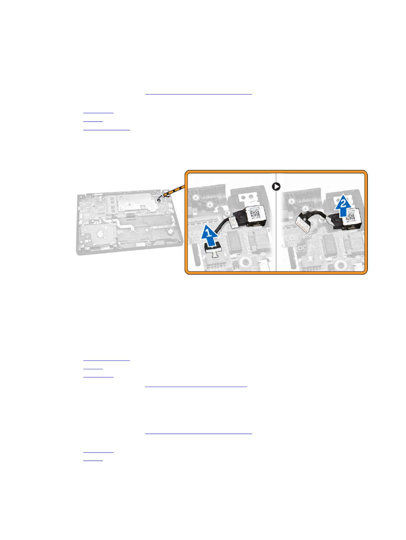
Removing the Power-Connector Port
1. Follow the procedures in .Before Working Inside Your Computer
2. Remove the:
a. base cover
b. battery
c. display assembly
3. Perform the following steps:
a. Disconnect the power-connector port cable from its connector on the system board [1].
b. Remove the power-connector port from the computer [2].
Installing the Power-Connector Port
1. Insert the power-connector port into its place on the computer.
2. Connect the power-connector port cable to its connector on the system board.
3. Install the:
a. display assembly
b. battery
c. base cover
4. Follow the procedures in .After Working Inside Your Computer
Removing the Hard-Drive Assembly
1. Follow the procedures in .Before Working Inside Your Computer
2. Remove the:
a. base cover
b. battery
19
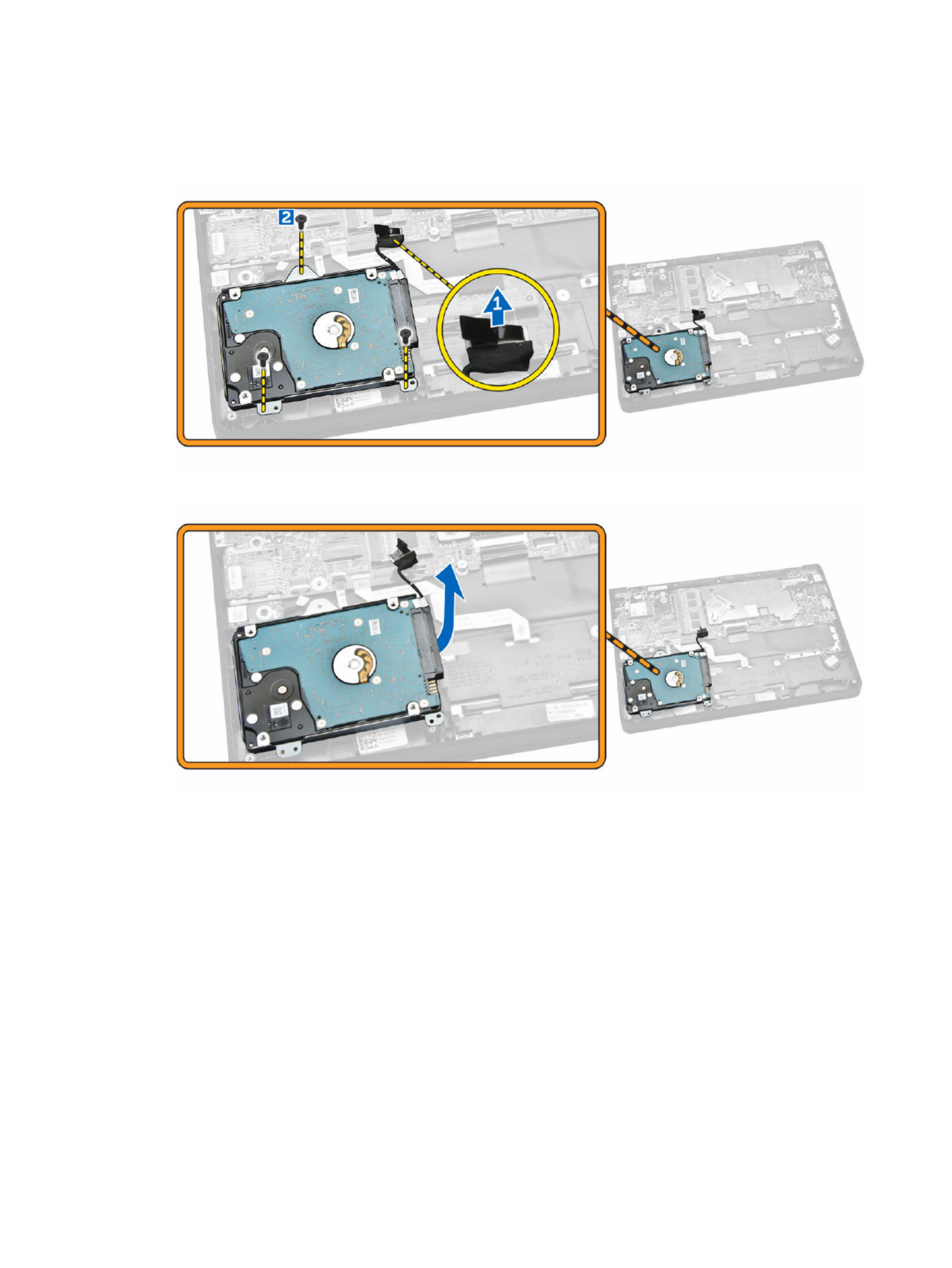
3. Perform the following steps:
a. Disconnect the hard-drive cable from its connector on the system board [1].
b. Remove the screws that secure the hard-drive assembly to the computer [2].
4. Remove the hard-drive assembly from the computer.
5. Pull to release the hard-drive cable from its connector on the hard-drive assembly.
20

6. Install the:
a. battery
b. base cover
7. Follow the procedures in .After Working Inside Your Computer
Removing the LED Board
1. Follow the procedures in .Before Working Inside Your Computer
2. Remove the:
a. base cover
b. battery
c. hard-drive assembly
3. Perform the following steps:
a. Disconnect the LED board cable from its connector on the system board [1] [2].
b. Remove the screw that secures the LED board to the computer [3].
c. Remove the LED board from the computer [4].
Installing the LED Board
1. Insert the LED board into its place on the computer.
2. Tighten the screw to secure the LED board to the computer.
3. Connect the LED board cable to its connector on the system board.
4. Install the:
a. hard-drive assembly
b. battery
c. base cover
5. Follow the procedures in .After Working Inside Your Computer
22
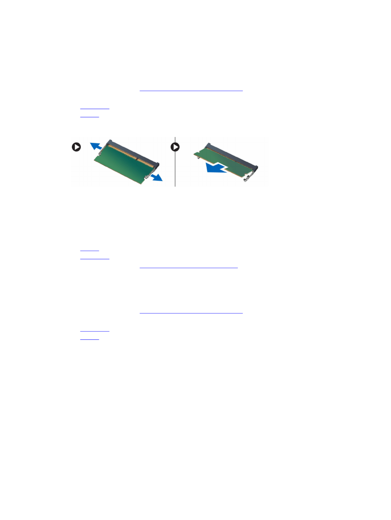
Removing the Memory
1. Follow the procedures in .Before Working Inside Your Computer
2. Remove the:
a. base cover
b. battery
3. Pry the clips securing the memory module until the memory pops-up and remove the memory from
the system board.
Installing the Memory
1. Insert the memory on the memory socket until the clips secure the memory.
2. Install the:
a. battery
b. base cover
3. Follow the procedures in .After Working Inside Your Computer
Removing the Coin-Cell Battery
1. Follow the procedures in .Before Working Inside Your Computer
2. Remove the:
a. base cover
b. battery
3. Perform the following steps:
a. Disconnect the coin-cell battery cable from its connector on the system board [1].
b. Peel the adhesive tape to release the coin-cell battery cable [2].
c. Release the coin-cell battery cable from its routing channels [3].
d. Pry the coin-cell battery to remove it from the computer [4].
23

Installing the Coin-Cell Battery
1. Insert the coin-cell battery in its place on the computer.
2. Route the coin-cell battery cable along its routing channels.
3. Fix the adhesive tape to secure the coin-cell battery cable.
4. Connect the coin-cell battery cable to its connector on the system board.
5. Install the:
a. battery
b. base cover
6. Follow the procedures in .After Working Inside Your Computer
Removing the Keyboard Trim
1. Follow the steps in .Before Working Inside Your Computer
2. Pry the keyboard trim from its edges.
24

NOTE:
NOTE:
NOTE:
NOTE: NOTE: You may need a sharp tool to pry the keyboard trim from its edges.
3. Remove the keyboard trim from the keyboard.
Installing the Keyboard Trim
1. Insert the keyboard trim to the keyboard until it snaps in its place.
2. Follow the procedures in .After Working Inside Your Computer
Removing the Keyboard
1. Follow the procedures in .Before Working Inside Your Computer
2. Remove the:
a. battery
b. base cover
25
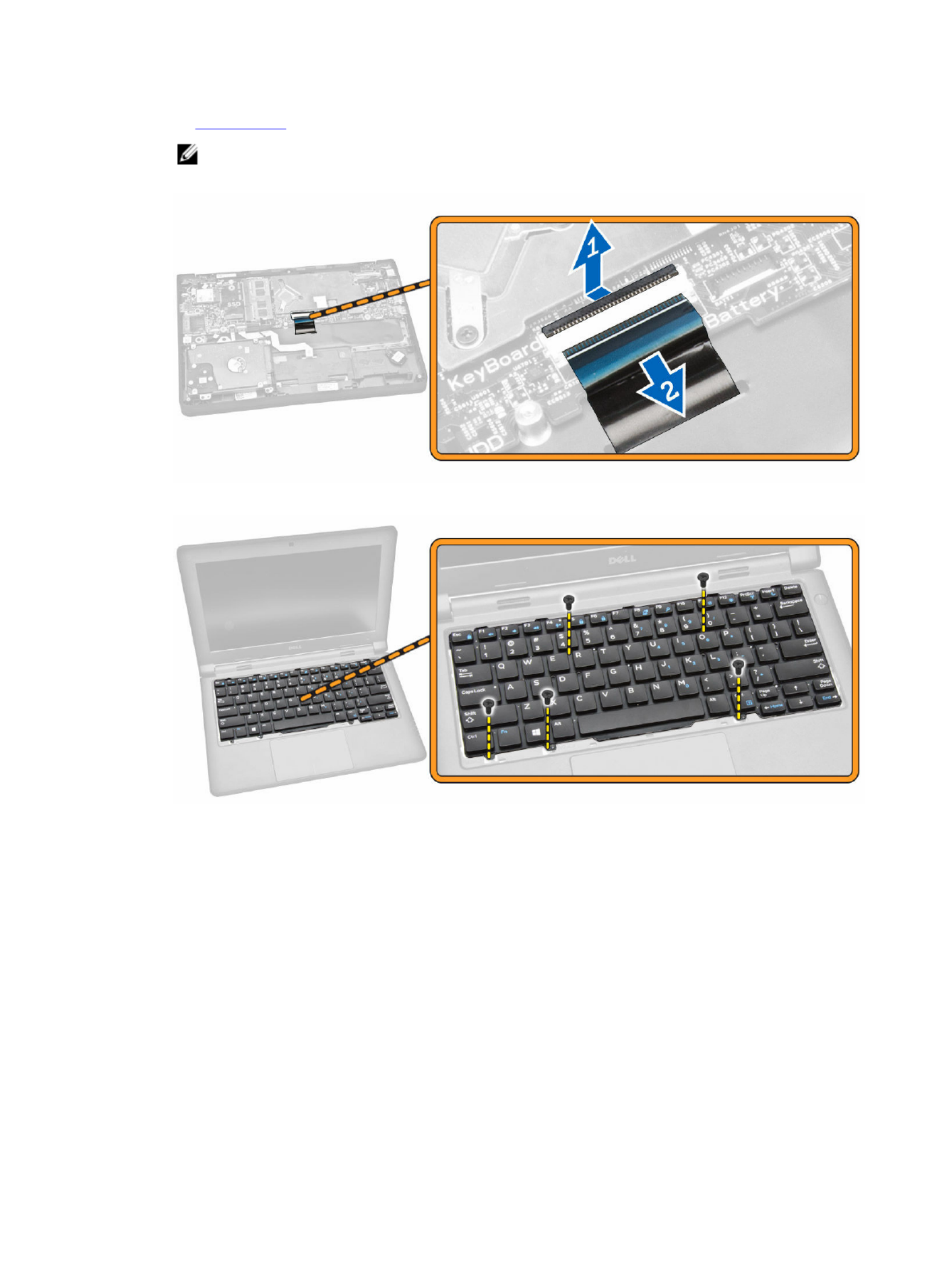
c. keyboard trim
NOTE:
NOTE:
NOTE:
NOTE: NOTE: After removing the keyboard trim, flip the computer to access the keyboard cable.
3. Disconnect the keyboard cable from its connector on the system board [1] [2].
4. Flip the computer and remove the screws that secure the keyboard to the computer.
5. Perform the following steps:
a. Pry the keyboard to release it from the computer [1].
b. Remove the keyboard from the computer [2].
26

Installing the Keyboard
1. Place the keyboard to align with the screw holders on the computer.
2. Flip the computer and connect the keyboard cable to its connector on the system board.
3. Tighten the screws to secure the keyboard to the computer.
4. Install the:
a. keyboard trim
b. battery
c. base cover
5. Follow the procedures in .After Working Inside Your Computer
Removing the Heatsink
1. Follow the procedures in .Before Working Inside Your Computer
2. Remove the:
a. base cover
b. battery
3. To release the heatsink from the system board:
a. Remove the screws that secure the heatsink from the metal bracket [1].
b. Remove the metal bracket from the system board [2].
c. Remove the screw that secures the heatsink to the system board [3].
27

4. Perform the following steps:
a. Remove the screws that secure the heatsink to the system board [1] [2] [3].
b. Remove the heatsink from the system board [4].
Installing the Heatsink
1. Insert the heatsink into its place on the system board.
2. Place the metal bracket and tighten the screws to secure the metal bracket to the system board.
3. Tighten the screws to secure the heatsink to the system board.
4. Install the:
a. battery
b. base cover
5. Follow the procedures in .After Working Inside Your Computer
28

Removing the System Board
1. Follow the procedures in .Before Working Inside Your Computer
2. Remove the:
a. base cover
b. battery
c. memory
d. heatsink
3. Disconnect the following cables from the system board [1] [2]:
a. keyboard
b. touchpad
c. LED board
d. network and speaker [3]
e. hard-drive assembly [4]
f. coin-cell battery and power-connector port [5]
g. display [6]
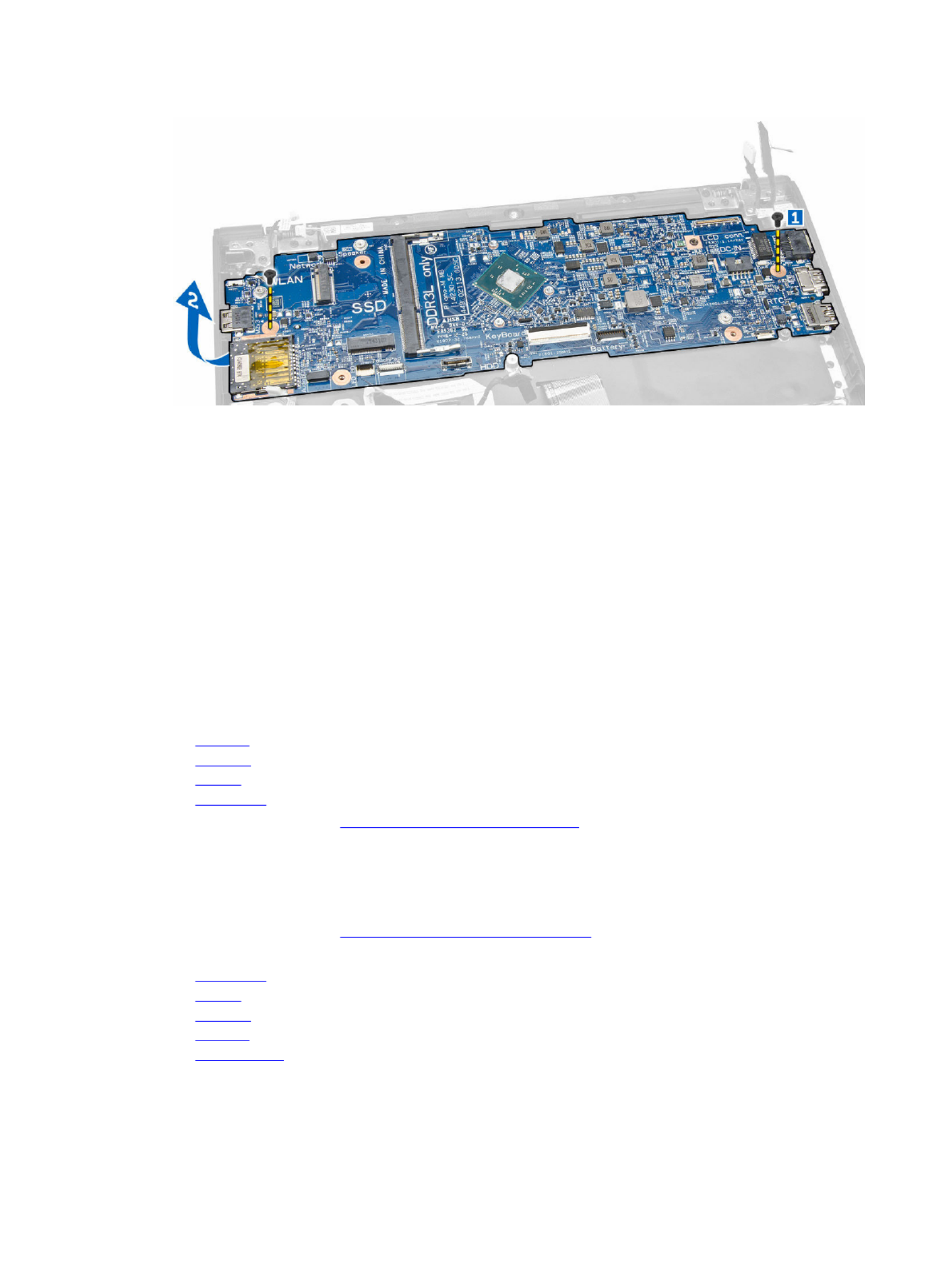
4. Perform the following steps to remove the system board from the computer:
a. Remove the screws that secure the system board to the computer [1].
b. Remove the system board from the computer [2].
29
Installing the System Board
1. Insert the system board into its place on the computer.
2. Tighten the screws to secure the system board to the computer.
3. Connect the following cables to their connectors on the system board:
a. display
b. coin-cell battery and power-connector port
c. hard-drive assembly
d. network and speaker
e. LED board
f. touchpad
g. keyboard
4. Install the:
a. heatsink
b. memory
c. battery
d. base cover
5. Follow the procedures in .After Working Inside Your Computer
Removing the Speaker
1. Follow the procedures in .Before Working Inside Your Computer
2. Remove the:
a. base cover
b. battery
c. memory
d. heatsink
e. system board
3. Perform the following steps:
30

a. Remove the screws that secure the speaker to the computer [1].
b. Remove the speaker from the computer [2].
Installing the Speaker
1. Insert the speaker into its place on the computer.
2. Tighten the screws to secure the speaker to the computer.
3. Install the:
a. system board
b. heatsink
c. memory
d. battery
e. base cover
4. Follow the procedures in .After Working Inside Your Computer
31

3
System Setup
System Setup enables you to manage your computer hardware and specify BIOS level options. From the ‐
System Setup, you can:
• Change the NVRAM settings after you add or remove hardware
• View the system hardware configuration
• Enable or disable integrated devices
• Set performance and power management thresholds
• Manage your computer security
Boot Sequence
Boot Sequence allows you to bypass the System Setup defined boot device order and boot directly to a ‐
specific device (for example: optical drive or hard drive). During the Power-on Self Test (POST), when the
Dell logo appears, you can:
• Access System Setup by pressing <F2> key
• Bring up the one-time boot menu by pressing <F12> key
The one-time boot menu displays the devices that you can boot from including the diagnostic option.
The boot-menu options are:
• Removable Drive (if available)
• STXXXX Drive
NOTE:
NOTE:
NOTE:
NOTE: NOTE: XXX denotes the SATA drive number.
• Optical Drive
• Diagnostics
NOTE:
NOTE:
NOTE:
NOTE: NOTE: Choosing Diagnostics, will display the screen.ePSA diagnostics
The boot sequence screen also displays the option to access the System Setup screen.
Navigation Keys
The following table displays the system setup navigation keys.
NOTE:
NOTE:
NOTE:
NOTE: NOTE: For most of the system setup options, changes that you make are recorded but do not take
effect until you re-start the system.
32

Table 1. Navigation Keys
Keys Navigation
Up arrow Moves to the previous field.
Down arrow Moves to the next field.
<Enter> Allows you to select a value in the selected field (if applicable) or follow the link in
the field.
Spacebar Expands or collapses a drop down list, if applicable.‐
<Tab> Moves to the next focus area.
NOTE:
NOTE:
NOTE:
NOTE: NOTE: For the standard graphics browser only.
<Esc> Moves to the previous page till you view the main screen. Pressing <Esc> in the main
screen displays a message that prompts you to save any unsaved changes and
restarts the system.
<F1> Displays the System Setup help file.
System Setup Options
NOTE:
NOTE:
NOTE:
NOTE: NOTE: Depending on your computer and its installed devices, the items listed in this section may or
may not appear.
Table 2. General
Option Description
System Information This section lists the primary hardware
features of your computer.
• System Information
• Memory Information
• Processor Information
• Device Information
Battery Information Displays the charge status of the battery.
Boot Sequence Allows you to change the order in which
the computer attempts to find an
operating system. All the options are
selected.
• Diskette Drive
• Internal HDD
• USB Storage Device
• CD/DVD/CD-RW Drive
• Onboard NIC
You can also choose the Boot List
option. The options are:
• Legacy
• UEFI
33

Option Description
Advanced Boot Options Allows you to enable the Legacy Option
ROMs during the UEFI boot mode. This
option is enabled by default.
Date/Time Allows you to set the date and time.
Table 3. System Configuration
Option Description
Integrated NIC Allows you to configure the integrated
network controller. The options are:
• Enabled UEFI Network Stack
• Disabled
• Enabled
• (Default Setting)Enabled w/PXE
NOTE:
NOTE:
NOTE:
NOTE: NOTE: If you enable this option, the
UEFI Networking Protocols that are
available are installed, allowing the
pre-OS and the OS networking
features to use the enabled NICs.
SATA Operation Allows you to configure the internal
SATA hard-drive controller. The options
are:
• Disabled
• (Default Setting)AHCI
NOTE:
NOTE:
NOTE:
NOTE: NOTE: SATA is configured to
support AHCI mode.
Drives Allows you to configure the SATA drives
on board. The option is:
• SATA-0
• SATA-1
Default Setting: Both drives are enabled.
SMART Reporting This field controls if the hard drive errors
for the integrated drives are reported
during system startup. This technology
is part of the SMART (Self Monitoring
Analysis and Reporting Technology)
specification.
• — This Enable SMART Reporting
option is disabled by default.
USB Configuration Allows you to define the USB
configuration. The options are:
• Enable Boot Support
• Enable External USB Port
34

Option Description
Default Setting: All the options are
enabled.
USB PowerShare Allows you to configure the behavior of
the USB PowerShare feature. The option
is disabled by default.
• Enable USB PowerShare
Audio Allows you to enable or disable the
integrated audio controller.
• (Default Setting)Enable Audio
Miscellaneous Devices Allows you to enable or disable the
various on board devices. The options
are:
• Enable Microphone
• Enable Hard Drive Free Fall
Protection
• Enable Camera
• Enable Media Card
• Disable Media Card
Default Setting: All devices are enabled.
Table 4. Video
Option Description
LCD Brightness Allows you to set the panel brightness when the ambient sensor is Off.
Table 5. Security
Option Description
Admin Password Allows you to set, change, or delete the administrator (admin) password.
NOTE:
NOTE:
NOTE:
NOTE: NOTE: You must set the admin password first if an admin password is
used with a system password and/or hard-drive password
NOTE:
NOTE:
NOTE:
NOTE: NOTE: Successful password changes take effect immediately.
NOTE:
NOTE:
NOTE:
NOTE: NOTE: Deleting the admin password automatically deletes the system
password and the hard-drive password.
NOTE:
NOTE:
NOTE:
NOTE: NOTE: Successful password changes take effect immediately.
Default Setting: Not set
System Password Allows you to set, change or delete the system password.
NOTE:
NOTE:
NOTE:
NOTE: NOTE: Successful password changes take effect immediately.
Default Setting: Not set
Internal HDD-0 Password Allows you to set, change, or delete the administrator (admin) password.
35

Option Description
Default Setting: Not set
Strong Password Allows you to enforce the option to always set strong passwords.
Default Setting: is disabled.Enable Strong Password
Password Configuration You can define the length of your password. Min = 4, Max = 32
Password Bypass Allows you to enable or disable the permission to bypass the System and
the Internal HDD password, when they are set. The options are:
• (Default Setting)Disabled
• Reboot bypass
Password Change Allows you to enable the disable permission to the system and hard-drive
passwords when the admin password is set.
Default Setting: is selected.Allow Non-Admin Password Changes
Non-Admin Setup
Changes
Allows you to determine whether changes to setup option are permitted
when an administrator password is set. The option is disabled.
• Allows Wireless Switch Changes
PTT Security Allows you to enable the Firmware TPM 2.0 function. The option is enabled.
Default Setting: Intel Platform Trust Security
Computrace Allows you to activate or disable the optional Computrace software The
options are:
• (Default Setting)Deactivate
• Disable
• Activate
NOTE:
NOTE:
NOTE:
NOTE: NOTE: The Activate and Disable options will permanently activate or
disable the feature and no further changes will be allowed.
CPU XD Support Allows you to enable the Execute Disable mode of the processor.
Default Setting: Enable CPU XD Support
Admin Setup Lockout Allows you to prevent users from entering Setup when an Administrator
password is set.
Default Setting: Disabled
Table 6. Secure Boot
Option Description
Secure Boot Enable Allows you to enable or disable the
secure boot. The options are:
• Disabled
• (Default Setting)Enabled
Expert Key Management Allows you to manipulate the security
key databases only if the system is in
Custom Mode. The Enable Custom
36

Option Description
Mode option is disabled by default. The
options are:
• PK
• KEK
• db
• dbx
If you enable the , the Custom Mode
relevant options for PK, KEK, db, and
dbx appear. The options are:
• –Saves the key to a user-Save to File
selected file
• – Replaces the Replace from File
current key with a key from a user-
selected file
• – Adds a key to the Append from File
current database from a user-
selected file
• – Deletes the selected keyDelete
• – Resets to default Reset All Keys
setting
• – Deletes all the keysDelete All Keys
NOTE:
NOTE:
NOTE:
NOTE: NOTE: If you disable the Custom
Mode, all the changes made will be
erased and the keys will restore to
default settings.
Table 7. Performance
Option Description
C-States Control Allows you to enable or disable the
additional processor sleep states.
Default Setting: .Enable C states
Table 8. Power Management
Option Description
AC Behavior Allows the computer to power on automatically, when AC adapter is
plugged. The option is disabled.
• Wake on AC
Auto On Time Allows you to set the time at which the computer must turn on
automatically. The options are:
• (Default Setting)Disabled
• Every Day
• Weekdays
• Select Days
37

Option Description
Numlock Enable Allows you to enable the Numlock when system boots. The option is
enabled by default.
Fn Key Emulation Allows you to match the <Scroll Lock> key feature of PS-2 keyboard with
the <Fn> key feature in an internal keyboard. The option is enabled by
default.
• Enable Fn Key Emulation
Fn Lock Options <Fn> +<Esc> This option when enabled allows the hot key combination
toggle the primary behavior of <F1> – <F12> between their standard and
secondary functions.
• (Default Setting)Fn Lock Hot Key
– (Default Setting)Standard
– Secondary
Fastboot Allows you to speed up the boot processes. The options are:
• Minimal
• - (Default Setting)Thorough
• Auto
Extend BIOS POST Time This option creates an extra pre-boot delay. This allows you to see the
POST status messages.
• (Default Setting)0 seconds
• 5 seconds
• 10 seconds
Table 10. Virtualization Support
Option Description
Virtualization This option specifies whether a Virtual Machine Monitor (VMM) can utilize
the additional hardware capabilities provided by Intel Virtualization
technology.
• (Default Setting)Enable Intel Virtualization Technology
Table 11. Wireless
Option Description
Wireless Switch Allows you to determine which wireless device can be controlled by the
wireless switch. The options are:
• Bluetooth
• WLAN
All options are enabled by default.
NOTE:
NOTE:
NOTE:
NOTE: NOTE: For Windows 8.1 Operating System, the option Wireless Switch
is directly controlled by the OS driver. So, this setting here does not
affect the .Wireless Switch Behavior
Wireless Device Enable Allows you to enable or disable the internal wireless devices. The options
are:
39

Option Description
• Bluetooth
• WLAN
All options are enabled by default.
Lid-Mounted Wireless
Activity LED
This field allows you to control the wireless activity LED mounted on the lid
of the system.
• Always Off
• (Default Setting)Led Indicates Wireless Activity
Table 12. Maintenance
Option Description
Service Tag Displays the Service Tag of your computer.
Asset Tag Allows you to create a system asset tag if an asset tag is not already set. This
option is not set by default.
BIOS Downgrade Allows you to control the flashing of the system firmware to the previous
revisions. This option is enabled by default
• Allow BIOS Downgrade
NOTE:
NOTE:
NOTE:
NOTE: NOTE: If you disable this option, the flashing of the system firmware to
a previous revision will be blocked.
Table 13. System Logs
Option Description
BIOS Events Displays the BIOS event log and allows you to clear the log.
• Clear Log
Thermal Events Displays the Thermal event log and allows you to clear the log.
• Clear Log
Power Events Displays the Power event log and allows you to clear the log.
• Clear Log
Updating the BIOS
It is recommended to update your BIOS (system setup), on replacing the system board or if an update is
available. For laptops, ensure that your computer battery is fully charged and connected to a power
outlet
1. Re-start the computer.
2. dell.com/supportGo to .
3. Service Tag Express Service Code SubmitEnter the or and click .
NOTE:
NOTE:
NOTE:
NOTE: NOTE: To locate the Service Tag, click Where is my Service Tag?
40

NOTE:
NOTE:
NOTE:
NOTE: NOTE: If you cannot find your Service Tag, click . Proceed with the Detect My Product
instructions on screen.
4. If you are unable to locate or find the Service Tag, click the Product Category of your computer.
5. Product TypeChoose the from the list.
6. Product SupportSelect your computer model and the page of your computer appears.
7. Get drivers View All DriversClick and click .
The Drivers and Downloads page opens.
8. Operating System BIOSOn the Drivers and Downloads screen, under the drop-down list, select .
9. Download FileIdentify the latest BIOS file and click .
You can also analyze which drivers need an update. To do this for your product, click Analyze
System for Updates and follow the instructions on the screen.
10. Please select your download method below Select your preferred download method in the window,
click Download File.
The window appears.File Download
11. SaveClick to save the file on your computer.
12. RunClick to install the updated BIOS settings on your computer.
Follow the instructions on the screen.
System and Setup Password
You can create a system password and a setup password to secure your computer.
Password Type
Password Type
Password Type
Password TypePassword Type Description
Description
Description
DescriptionDescription
System password
System password
System password
System passwordSystem password Password that you must enter to log on to your system.
Setup password
Setup password
Setup password
Setup passwordSetup password Password that you must enter to access and make changes to the BIOS settings of
your computer.
CAUTION: The password features provide a basic level of security for the data on your computer.
CAUTION: Anyone can access the data stored on your computer if it is not locked and left
unattended.
NOTE:
NOTE:
NOTE:
NOTE: NOTE: Your computer is shipped with the system and setup password feature disabled.
Assigning a System Password and Setup Password
You can assign a new and/or or change an existingSystem Password Setup Password System Password
and/or only when is . If the Password Status is , you Setup Password Password Status Unlocked Locked
cannot change the System Password.
NOTE:
NOTE:
NOTE:
NOTE: NOTE: If the password jumper is disabled, the existing System Password and Setup Password are
deleted and you need not provide the system password to log on to the computer.
To enter a system setup, press <F2> immediately after a power-on or re-boot.
1. System BIOS System Setup System SecurityIn the or screen, select and press <Enter>.
41

The screen appears.System Security
2. System Security Password Status UnlockedIn the screen, verify that is .
3. System Password Select , enter your system password, and press <Enter> or <Tab>.
Use the following guidelines to assign the system password:
• A password can have up to 32 characters.
• The password can contain the numbers 0 through 9.
• Only lower case letters are valid, upper case letters are not allowed.
• Only the following special characters are allowed: space, (”), (+), (,), (-), (.), (/), (;), ([), (\), (]), (`).
Re-enter the system password when prompted.
4. OKType the system password that you entered earlier and click .
5. Setup PasswordSelect , type your system password and press <Enter> or <Tab>.
A message prompts you to re-type the setup password.
6. OKType the setup password that you entered earlier and click .
7. Press <Esc> and a message prompts you to save the changes.
8. Press <Y> to save the changes.
The computer reboots.
Deleting or Changing an Existing System and/or Setup Password
Ensure that the is Unlocked (in the System Setup) before attempting to delete or change Password Status
the existing System and/or Setup password. You cannot delete or change an existing System or Setup
password, if the Password Status is Locked.
To enter the System Setup, press <F2> immediately after a power-on or reboot.
1. System BIOS System Setup System SecurityIn the or screen, select and press <Enter>.
The screen is displayed.System Security
2. System Security Password Status UnlockedIn the screen, verify that is .
3. System PasswordSelect , alter or delete the existing system password and press <Enter> or <Tab>.
4. Setup PasswordSelect , alter or delete the existing setup password and press <Enter> or <Tab>.
NOTE:
NOTE:
NOTE:
NOTE: NOTE: If you change the System and/or Setup password, re-enter the new password when
promoted. If you delete the System and/or Setup password, confirm the deletion when
promoted.
5. Press <Esc> and a message prompts you to save the changes.
6. Press <Y> to save the changes and exit from the System Setup.
The computer reboots.
42

4
Technical Specifications
NOTE:
NOTE:
NOTE:
NOTE: NOTE: Offerings may vary by region. The following specifications are only those required by law to
ship with your computer. For more information about the configuration of your computer, go to
Help and Support in your Windows operating system and select the option to view information
about your computer.
System Information
Chipset Intel Braswell (Integrated with the processor)
Processor
Type • Intel Pentium
• Intel Celeron
Video
Video type Integrated on system board
Data bus Integrated video
Video controller:
Intel Pentium Intel Integrated HD Graphics
Intel Celeron
Memory
Memory connector One SODIMM slot
Memory capacity 2 GB, 4 GB, and 8 GB
Memory type 1600 MHz DDR3L
Minimum memory 2 GB
Maximum memory 8 GB
Audio
Type Two-channel high definition audio
Controller Realtek ALC3234–CG Controller
Stereo Conversion 24-bit (analog-to-digital and digital-to-analog)
Interface:
Internal High-definition audio
External Microphone-in/stereo headphones combo connector
Speakers Two (2W per channel)
43

AC Adapter
Type 65W 65W HF-free / Non-HF
free
90W (India only)
Rated output voltage 19.50 VDC 19.50 VDC 19.5 VDC
Dimensions:
Height 22.00 mm (0.87 inch) 28.00 mm (1.10 inches) 32.00 mm (1.30 inches)
Width 66.00 mm (2.60 inches) 47.00 mm (1.90 inches) 52.00 (2.00 inches)
Depth 106.00 mm (4.17
inches)
108.00 mm (4.30
inches)
128.00 (5.00 inches)
Temperature range:
Operating 0 °C to 40 °C (32 °F to 104 °F)
Non Operating –40 °C to 70 °C (–40 °F to 158 °F)
Physical
Height (with a WLED panel) 22.90 mm (0.90 inch)
Width 301.00 mm (11.85.0 inches)
Depth 212.00 mm (8.35 inches)
Weight (Minimum) 1.68 kg (3.70 lb)
Environmental
Temperature range:
Operating 5 °C to 60 °C (41 °F to 140 °F)
Storage -40 °C to 65 °C (–40 °F to 149 °F)
Relative humidity (maximum):
Operating 10 % to 90 % (non-condensing)
Storage 5 % to 95 % (non-condensing)
Altitude (maximum):
Operating –15.2 m to 3048 m (–50 to 10,000 ft)
0° C to 35°C
Non-Operating -15.20 m to 10,668 m (-50 ft to 35,000 ft)
Maximum vibration:
Operating 0.66 Grms (2 Hz - 600 Hz)
Storage 1.30 Grms (2 Hz - 600 Hz)
Maximum shock:
Operating 110 G
Storage 160 G
Airborne contaminant level G1 or lower as defined by ISA-S71.04–1985
46
Product specificaties
| Merk: | Dell |
| Categorie: | Laptop |
| Model: | Latitude 3160 |
| Kleur van het product: | Zwart |
| Gewicht: | 1480 g |
| Breedte: | 301 mm |
| Diepte: | 212 mm |
| Gebruikershandleiding: | Ja |
| Bluetooth: | Ja |
| Beeldschermdiagonaal: | 11.6 " |
| Resolutie: | 1366 x 768 Pixels |
| Touchscreen: | Ja |
| Oorspronkelijke beeldverhouding: | 16:9 |
| Frequentie van processor: | 1.6 GHz |
| Processorfamilie: | Intel® Pentium® |
| Processormodel: | N3700 |
| Aantal processorkernen: | 4 |
| Wi-Fi-standaarden: | 802.11a,802.11g,Wi-Fi 4 (802.11n) |
| Bluetooth-versie: | 4.0 |
| Vormfactor: | Clamshell |
| Inclusief besturingssysteem: | Windows 7 Professional |
| Ethernet LAN: | Ja |
| Geïntegreerde geheugenkaartlezer: | Ja |
| Compatibele geheugenkaarten: | SD |
| Audiosysteem: | HD |
| Helderheid: | 220 cd/m² |
| Processor lithografie: | 14 nm |
| Inclusief AC-adapter: | Ja |
| Markt positionering: | Educatief |
| LED backlight: | Ja |
| Aantal HDMI-poorten: | 1 |
| Microfoon, line-in ingang: | Nee |
| DVI-poort: | Nee |
| Aantal Ethernet LAN (RJ-45)-poorten: | 1 |
| Bevestigingsmogelijkheid voor kabelslot: | Ja |
| Aantal ingebouwde luidsprekers: | 2 |
| Wachtwoordbeveiliging: | Ja |
| AC-adapter, vermogen: | 65 W |
| Inclusief netsnoer: | Ja |
| Ingebouwde microfoon: | Ja |
| Intern geheugen: | 4 GB |
| Opslagmedia: | HDD |
| Levensduur accu/batterij: | - uur |
| Intern geheugentype: | DDR3L-SDRAM |
| Duurzaamheidscertificaten: | EPEAT Gold,ENERGY STAR |
| Ethernet LAN, data-overdrachtsnelheden: | 10,100,1000 Mbit/s |
| Intel® Wireless Display (Intel® WiDi): | Ja |
| Aantal poorten USB 3.2 Gen 1 (3.1 Gen 1) Type A: | 2 |
| Processor socket: | BGA 1170 |
| Stepping: | C0 |
| Systeembus: | 2.5 GT/s |
| Processor aantal threads: | 4 |
| PCI Express slots versie: | 2.0 |
| Processor operating modes: | 64-bit |
| Processor cache: | 2 MB |
| Tjunction: | 90 °C |
| PCI Express configuraties: | 1x2,1x4,2x2,2x1,4x1 |
| Thermal Design Power (TDP): | 6 W |
| Codenaam processor: | Braswell |
| Maximaal aantal PCI Express-lijnen: | 4 |
| Processor cache type: | L2 |
| ECC ondersteund door processor: | Nee |
| Processorfabrikant: | Intel |
| Architectuur besturingssysteem: | 64-bit |
| Maximum intern geheugen: | 8 GB |
| Totale opslagcapaciteit: | 250 GB |
| Ingebouwde grafische adapter: | Ja |
| Familie ingebouwde grafische adapter: | Intel® HD Graphics |
| On-board graphics adapter model: | Intel® HD Graphics |
| Basisfrequentie ingebouwde grafische adapter: | 400 MHz |
| Maximaal geheugen ingebouwde grafische adapter: | 8 GB |
| On-board grafische adapter DirectX-versie: | Ja |
| Camera voorzijde: | Ja |
| Numeriek toetsenblok: | Nee |
| Intel® My WiFi Technology (Intel® MWT): | Nee |
| Intel® Smart Response Technology: | Nee |
| Intel® Hyper Threading Technology (Intel® HT Technology): | Nee |
| Intel® Turbo Boost Technology: | Nee |
| Intel® Quick Sync Video Technology: | Ja |
| Intel® InTru™ 3D Technology: | Nee |
| Intel® Clear Video HD Technology (Intel® CVT HD): | Ja |
| Intel® Insider™: | Nee |
| Intel® Flex Memory Access: | Nee |
| Intel® AES New Instructions (Intel® AES-NI): | Ja |
| Enhanced Intel SpeedStep Technology: | Ja |
| Execute Disable Bit: | Ja |
| Idle States: | Ja |
| Thermal Monitoring Technologies: | Ja |
| CPU configuratie (max): | 1 |
| Intel® Enhanced Halt State: | Ja |
| Intel® Clear Video Technology for Mobile Internet Devices (Intel® CVT for MID): | Ja |
| Intel® VT-x with Extended Page Tables (EPT): | Ja |
| Ingebouwde opties beschikbaar: | Nee |
| Intel® Small Business Advantage (Intel® SBA): | Nee |
| Intel® Secure Key: | Ja |
| Intel® 64: | Ja |
| Intel® OS Guard: | Nee |
| Intel® Virtualization Technology for Directed I/O (VT-d): | Nee |
| Intel® Clear Video-technologie: | Ja |
| Intel® Virtualization Technology (VT-x): | Ja |
| Verpakkingsgrootte processor: | 25 x 27 mm |
| Conflictvrije processor: | Ja |
| Intel® Identity Protection Technology (Intel® IPT): | Ja |
| Versie Intel® Identity Protection Technology: | 1.00 |
| Versie Intel® Secure Key Technology: | 1.00 |
| Versie Intel® Smart Response Technology: | 0.00 |
| ARK ID processor: | 87261 |
| Intel® Trusted Execution Technology: | Nee |
| Intel® Stable Image Platform Program (SIPP): | Nee |
| Versie Intel® Stable Image Platform Program (SIPP): | 0.00 |
| Intel® Anti-Theft Technology (Intel® AT): | Nee |
| Intel® Rapid Start Technology: | Nee |
| Intel® Smart Connect Technology: | Nee |
| Basisstationaansluiting: | Nee |
| Combo koptelefoon/microfoon port: | Ja |
| SmartCard-slot: | Nee |
| Maximale turbofrequentie van processor: | 2.4 GHz |
| Processorcode: | SR29E |
| Aanwijsapparaat: | Touchpad |
| Windows-toetsen: | Ja |
| Kloksnelheid geheugen: | 1600 MHz |
| Geheugenlayout: | 1 x 4 GB |
| Geheugen form factor: | SO-DIMM |
| Full-size toetsenbord: | Ja |
| Aantal verwerkingseenheden: | 16 |
| Het aantal geïnstalleerde HDD's: | 1 |
| HDD capaciteit: | 250 GB |
| HDD interface: | SATA |
| FSB Parity: | Nee |
| Front-side bus processor: | - MHz |
| Intel® Demand Based Switching: | Nee |
| On-board grafische adapter burst frequentie: | 700 MHz |
| UART: | Ja |
| Charging port type: | DC-in ingang |
| Type CardBus PCMCIA-slot: | Nee |
| Processorserie: | Intel® Pentium N3000 Series voor Mobile |
| ExpressCard slot: | Nee |
| S/PDIF-uitgang: | Nee |
| Hoogte (voorzijde): | 22.9 mm |
| Hoogte (achterzijde): | 23.65 mm |
| Intel® Dual Display Capable Technology: | Nee |
| Intel® FDI Technology: | Nee |
| Intel® Rapid Storage Technology: | Nee |
| Intel® Fast Memory Access: | Nee |
| Intel® Small Business Advantage (SBA)-versie: | 0.00 |
| Scenario Design Power (SDP): | 4 W |
| Intel® Veilig opstarten: | Ja |
| Versie Intel® Secure Boot Technology: | 1.00 |
| Intel® segment tagging: | Onderwijs |
| HDD omvang: | 2.5 " |
| Intel® High Definition Audio (Intel® HD Audio): | Ja |
| Versie Intel® Smart Connect Technology: | 0.00 |
| Resolutie camera voorzijde: | 1280 x 720 Pixels |
| Intel® Virtualization Technology (Intel® VT): | VT-x |
| Aantal SATA III connectors: | 2 |
| Herstel besturingssysteem: | Windows 8.1 |
| Maximaal intern geheugen (64-bit): | 8 GB |
| Wifi: | Ja |
| Type product: | Notebook |
| Intel® Matrix Storage Technology (Intel® MST): | Nee |
| Intel® Active Management Technology (Intel® AMT): | Nee |
| Batterijtechnologie: | Lithium-Polymeer (LiPo) |
| Aantal batterijcellen: | 3 |
| Geïntegreerde 4G WiMAX: | Nee |
| Totaal aantal SATA-connectoren: | 2 |
| Intel® Pro Wireless Display (Intel® Pro WiDi): | Ja |
Heb je hulp nodig?
Als je hulp nodig hebt met Dell Latitude 3160 stel dan hieronder een vraag en andere gebruikers zullen je antwoorden
Handleiding Laptop Dell

27 Januari 2025
3 December 2024
3 December 2024
3 December 2024
3 December 2024
3 December 2024
3 December 2024
3 December 2024
16 November 2024
4 September 2024
Handleiding Laptop
- Laptop HP
- Laptop Sony
- Laptop Samsung
- Laptop Xiaomi
- Laptop Panasonic
- Laptop LG
- Laptop Huawei
- Laptop Asus
- Laptop Medion
- Laptop Toshiba
- Laptop Acer
- Laptop Airis
- Laptop Alienware
- Laptop Apple
- Laptop Denver
- Laptop Emachines
- Laptop Ematic
- Laptop Evga
- Laptop Fellowes
- Laptop Fujitsu
- Laptop Gigabyte
- Laptop Goclever
- Laptop Haier
- Laptop Hannspree
- Laptop Hercules
- Laptop Honor
- Laptop Hyundai
- Laptop Ibm
- Laptop Kogan
- Laptop Lenovo
- Laptop Lexibook
- Laptop Micromax
- Laptop Microsoft
- Laptop Mpman
- Laptop MSI
- Laptop Nec
- Laptop Packard Bell
- Laptop Peaq
- Laptop Pyle
- Laptop Razer
- Laptop Ricatech
- Laptop Schneider
- Laptop Sylvania
- Laptop Targa
- Laptop Thomson
- Laptop Trekstor
- Laptop Viewsonic
- Laptop Vizio
- Laptop Zebra
- Laptop Jay-tech
- Laptop Odys
- Laptop Olidata
- Laptop Oregon Scientific
- Laptop Naxa
- Laptop Aplic
- Laptop ADATA
- Laptop Humanscale
- Laptop Hamilton Buhl
- Laptop Compaq
- Laptop SIIG
- Laptop Tripp Lite
- Laptop SPC
- Laptop Prixton
- Laptop Coby
- Laptop AORUS
- Laptop Hähnel
- Laptop XPG
- Laptop ECS
- Laptop Inovia
- Laptop Ergotron
- Laptop Atdec
- Laptop Getac
- Laptop Vulcan
- Laptop System76
- Laptop General Dynamics Itronix
- Laptop CTL
- Laptop Everex
- Laptop Dynabook
- Laptop TechBite
- Laptop Schenker
Nieuwste handleidingen voor Laptop

2 April 2025

28 Maart 2025

27 Maart 2025
26 Maart 2025

4 Maart 2025
10 Februari 2025
10 Februari 2025
10 Februari 2025
5 Februari 2025
5 Februari 2025