Axis P1344-E Handleiding
Axis
Bewakingscamera
P1344-E
Lees hieronder de 📖 handleiding in het Nederlandse voor Axis P1344-E (62 pagina's) in de categorie Bewakingscamera. Deze handleiding was nuttig voor 23 personen en werd door 2 gebruikers gemiddeld met 4.5 sterren beoordeeld
Pagina 1/62


™
)


37
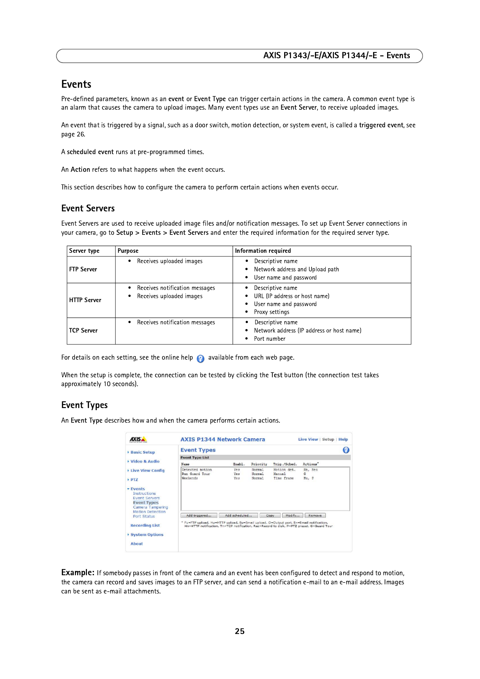
AXIS P1343/-E/AXIS P1344/-E - System Options
Traps for SNMP v1/v2
Traps are used by the camera to send messages to a management system for important events or status changes.
If Enable traps is selected, enter the email address where the trap message is to be sent as well as the Trap community that
should receive the message.
There are four types of traps available for AXIS P1343/-E/AXIS P1344/-E.
• Cold start
• Warm start
• Link up
• Authentication failed
SNMP v3
SNMP V3 - provides encryption and secure passwords. HTTPS must be enabled. To use traps with SNMP v3 an SNMP v3
management application is required.
If the option is enabled, provide the Initial user passwordEnable SNMP v3 . Note that the initial password is activated only
when HTTPS is enabled and can only be set once.
If HTTPS is enabled, SNMP v1 and SNMP v2c should be disabled.
When SNMP configuration is ready, click Save to use the new settings or Reset to return to the default values.
UPnP™
The network camera includes support for UPnP™. UPnP™ is enabled by default, and the network camera then is automatically
detected by operating systems and clients that support this protocol.
RTP/H.264
These settings are the port range, IP address, port number (video and audio), and Time-To-Live value to use for the video
stream(s) in multicast H.264 format. Only certain IP addresses and port numbers should be used for multicast streams. For
more information, please see the online help.
Bonjour
The network camera includes support for Bonjour. When enabled, the camera is automatically detected by operating systems
and clients that support this protocol.
Storage
SD Card
The Disk Management window is used to set up and manage local storage. It is used to connect memory cards for recording
video, monitoring a disk's status, enabling automatic cleanup, and preventing a memory card's memory from being
overwritten.
Storage Device - is used to identify and monitor the status of the SD card. It shows the size of the SD card and how much
free space is available for storage. It is also used to mount and format SD cards for local storage.
Device Settings - is used to configure removal of recorded video. Automatic disk cleanup can be enabled and set up
according to a schedule, and an SD card can be locked to prevent storage removal.

38
AXIS P1343/-E/AXIS P1344/-E - System Options
Ports & Devices
I/O Ports
AXIS P1343/-E/AXIS P1344/-E has one input and one output port. for connection of external devices. The ports can be given
descriptive names and their Normal states can be configured as Open circuit or Grounded circuit.
See
Unit connectors
, on page 41, for information on how to connect external devices.
LED
The Status indicator LED on the front of the camera can be set to flash at a configurable interval (or to not light up at all)
when the unit is accessed. For a listing of all LED behavior, see page 43.
Maintenance
Restart – The camera is restarted without changing any settings.
Restore – The unit is restarted and most curren ory default values. The settit settings are reset to fact ngs that do not reset are:
• the boot protocol (DHCP or static)
• the static IP address
• the default router
• the subnet mask
• the product interface language
• the system time
• the 802.1x settings
• the back focus position
Default – The default button should be used with caution. Pressing this returns the camera's settings to the factory default
values (including the IP address).
Upgrade Server – See
Upgrading the firmware
, on page 44.
Support
Support Overview
The Support Overview page provides valuable information on troubleshooting and contact information, should you require
technical assistance.
System Overview
System Overview is an overview of the camera’s status and settings. Information that can be found here includes the
camera’s firmware version, IP address, security, event and image settings and recent log items. Many of the captions are also
links to the proper Setup page to conveniently make adjustments in the camera’s settings.

39
AXIS P1343/-E/AXIS P1344/-E - System Options
Logs & Reports
When contacting Axis support, please be sure to provide a valid
Server Report with your query. The Access Log is automatically
included in the server report.
Information
The Server Report and Parameter List may prove useful when
troubleshooting a problem or when contacting the Axis support.
• System Log - Provides information about system
events.
• Access Log - By default, the Access Log lists all failed
attempts to access the camera but can be configured
to list all connections to the camera, whether
successful or not. Go to Support > Logs & Reports > Configuration and select the desired level of information
from the list. See below for more information. The Access Log is useful for various purposes such as tracking all
access to the camera, system analysis and troubleshooting.
• Server Report - Provides information about the server status and should always be included when requesting
support.
• Parameter List - Shows the unit's parameters and their current settings.
• Connection List - Lists all clients that are currently accessing video and audio. It is also used for system analysis
and troubleshooting.
• Crash Report – Generates an archive with debugging information. Note that the report takes several minutes to
generate.
Configuration
From the drop-down lists, select the size and level of information to be added to the System Log and Access Log files.
The default information level for the Access Log is set to Critical & Warnings, i.e. failed connections. However, in an error
situation and when requesting support, set it to the highest information level Critical & Warnings & Info.
For the Log Level for Email, select from the drop-down list the level of information to send as email and enter the destination
email address.
Advanced
Scripting
Scripting is an advanced function that enables you to customize and use scripts. This function is a very powerful tool.
Caution!
Improper use may cause unexpected behavior or even cause loss of contact with the unit. If a script does cause problems,
reset the unit to its factory default settings. A backup file may be of use to return the unit to its latest configuration.
Axis strongly recommends that you do not use this function unless you understand the consequences. Note that Axis
support does not provide assistance for problems with customized scripts.
For more information, please visit the Video developer pages at www.axis.com/developer
File Upload
Files (e.g. web pages and images) can be upload to AXIS P1343/-E/AXIS P1344/-E and used as custom settings. Uploaded files
are accessed through http;//<ip address>/local/<user>/<file name> where <user> is the selected user access group (viewer,
operator or administrator) for the uploaded file.
Plain Config
Plain Config is for the advanced user with experience of Axis network camera configuration. All parameters can be set and
modified from this page. Help is available from the standard help pages.

40
AXIS P1343/-E/AXIS P1344/-E - About
About
Here you can find basic information about your network camera. You can also view third party software licenses.
Resetting to Factory Default Settings
To reset the camera to the original factory default settings, go to the System Options > Maintenance web page (as described
in
Maintenance,
on page 38) or use the Control button on the side of the camera (see page 6) as described below:
Using the Control Button
This will reset all parameters, including the IP address and the focus position, to the factory default settings:
1. Disconnect power from the camera.
2. Press and hold the Control button and reconnect power.
3. Keep the Control button pressed until the Status indicator color changes to amber (this may take up to 15 seconds).
4. Release the Control button. When the Status indicator changes to green (which may take up to 1 minute), the process
is complete and the camera has been reset. The unit now has the default IP address 192.168.0.90
5. Re-assign the IP address, for instructions see the Installation Guide supplied with the camera.
6. Refocus the camera, for instructions see the Installation Guide supplied with the camera.

41
AXIS P1343/-E/AXIS P1344/-E - Unit connectors
Unit connectors
Network connector - RJ-45 Ethernet connector. Supports Power over Ethernet. Using shielded cables is recommended.
Power connector - 2-pin terminal block used for power input.
Audio in (pink) – 3.5 mm input for a mono microphone, or a line-in mono signal (left channel is used from a stereo signal).
Audio out (green) – Audio output (line level) that can be connected to a public address (PA) system or an active speaker with
a built-in amplifier. A pair of headphones can also be attached. A stereo connector must be used for the audio out.
SDHC memory card slot - A standard or high capacity SD memory card can be used for local recording with removable
storage.
To insert an SD card, lift the SD card cover on the rear of AXIS P1343/-E/AXIS P1344/-E, and carefully insert the SD card into
its slot.
To remove an SD card lift the cover and gently push the card in and release it. The SD card will come out of the slot and can
be removed.
Note:
Before removing the SD card, it should be unmounted to prevent corruption of recordings. To unmount the SD card, go
to Setup > System Options > Storage > SD Card > Disk Management and click Unmount.
Function Pin number Description
GND 1 Ground
DC Power 2 Power input 8-20V DC, max 6.4W.
1
2
SD memory card slot

42
AXIS P1343/-E/AXIS P1344/-E - Unit connectors
I/O terminal connector - Used in applications for e.g. motion detection, event triggering,
time lapse recording and alarm notifications. In addition to an auxiliary power and a GND
pin, it provides the interface to:
• 1 digital output - For connecting external devices such as relays and LEDs. Con-
nected devices can be activated by the VAPIX® Application Programming Interface,
output buttons on the Live View page or by an Event Type. The output will show as
active (shown under Events > Port Status) if the alarm device is activated.
• 1 digital input - An alarm input for connecting devices that can toggle between an
open and closed circuit, for example: PIRs, door/window contacts, glass break detectors, etc. When a signal is received
the state changes and the input becomes active (shown under Events > Port Status).
Notes:
• The I/O connector on AXIS P1343-E and AXIS P1344-E is connected to the housing electronics (fan/heater) at delivery,
see illustration on page 7, and will trigger an input port event to indicate a fan or heater error when activated. See
Events,
on page 25, for information on how to set up an event.
• For information on how to connect external devices, refer to the Installation Guide supplied with the product.
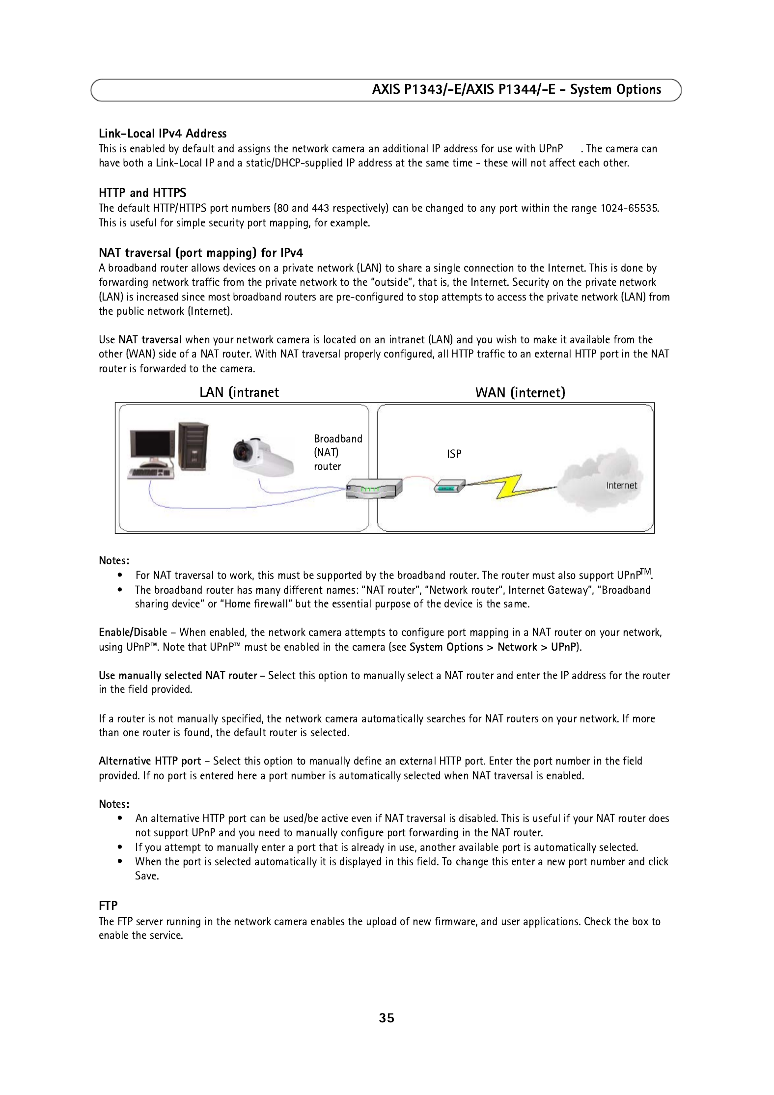
The following connection diagram gives an example of how to connect an auxiliary device to AXIS P1343/-E/AXIS P1344/-E.
Function Pin Notes Specifications
GND 1 Ground
3.3V DC Power 2 Can be used to power auxiliary equipment.
Note: This pin can only be used as power out.
Max load = 50mA
Digital Input 3 Connect to GND to activate, or leave floating (unconnected) to
deactivate.
AXIS P1343-E and AXIS P1344-E: Connected to housing electronics
at delivery.
Min. input = -40V DC
Max. input= +40V DC
Digital Output 4 Uses an open-drain NFET transistor with the source connected to
GND. If used with an external relay, a diode must be connected in
parallel with the load, for protection against voltage transients.
Max. load =100 mA
Max. voltage = + 40V DC
Pin 3
Pin 4 Pin 2
Pin 1
1
2
E.g. push button
3
4
3.3V
max. 50mA
D
S
G
Product specificaties
| Merk: | Axis |
| Categorie: | Bewakingscamera |
| Model: | P1344-E |
| Gewicht: | 3100 g |
| Processormodel: | ARTPEC-3 |
| Ondersteunde videoformaten: | H.264 |
| Maximum resolutie: | 1280 x 800 Pixels |
| Type stroombron: | Power over Ethernet (PoE) |
| Minimale belichting: | 0.3 Lux |
| Video bewegings-detectie: | Ja |
| Microfoon, line-in ingang: | Ja |
| Aantal Ethernet LAN (RJ-45)-poorten: | 1 |
| Brandpuntbereik: | 3 - 8 mm |
| Certificering: | EN 55022 Class B, EN 61000-3-2, EN 61000-3-3, EN 55024, FCC Part 15 Subpart B Class B, ICES-003 Class B, VCCI Class B, C-tick AS/NZS CISPR 22, EN 60950-1 |
| Omvang optische sensor: | 1/4 " |
| Type beeldsensor: | CMOS |
| Camera sluitertijd: | 1/24500 - 1/6 s |
| Intern geheugen: | 128 MB |
| Maximaal 30 frames per seconde: | 30 fps |
| Ondersteunde netwerkprotocollen: | IPv4/v6, HTTP, HTTPS, QoS Layer 3 DiffServ, FTP, SMTP, Bonjour, UPnP, SNMPv1/v2c/v3(MIB-II), DNS, DynDNS, NTP, RTSP, RTP, TCP, UDP, IGMP, RTCP, ICMP, DHCP, ARP, SOCKS |
| Flash memory: | 128 MB |
| Power over Ethernet (PoE): | Ja |
| Sample rate: | 8 kHz |
| Afmetingen (B x D x H): | 162 x 405 x 121 mm |
| Stroomverbruik (typisch): | 6.4 W |
| Bedrijfstemperatuur (T-T): | 0 - 50 °C |
| Relatieve vochtigheid in bedrijf (V-V): | 20 - 80 procent |
| Actieve ombevoegde demontage alarm: | Ja |
Heb je hulp nodig?
Als je hulp nodig hebt met Axis P1344-E stel dan hieronder een vraag en andere gebruikers zullen je antwoorden
Handleiding Bewakingscamera Axis

23 Februari 2025
20 Februari 2025
20 Februari 2025
27 December 2024
23 December 2024
11 December 2024
30 September 2024
30 September 2024
30 September 2024
30 September 2024
Handleiding Bewakingscamera
- Bewakingscamera Braun
- Bewakingscamera Bosch
- Bewakingscamera Philips
- Bewakingscamera Sony
- Bewakingscamera Samsung
- Bewakingscamera Xiaomi
- Bewakingscamera Panasonic
- Bewakingscamera Asus
- Bewakingscamera Canon
- Bewakingscamera Garmin
- Bewakingscamera Grundig
- Bewakingscamera Gigaset
- Bewakingscamera Honeywell
- Bewakingscamera JVC
- Bewakingscamera Motorola
- Bewakingscamera Pioneer
- Bewakingscamera Toshiba
- Bewakingscamera VTech
- Bewakingscamera Abus
- Bewakingscamera ACME
- Bewakingscamera Acti
- Bewakingscamera Ag Neovo
- Bewakingscamera Airlive
- Bewakingscamera Aldi
- Bewakingscamera Alecto
- Bewakingscamera Allnet
- Bewakingscamera Aluratek
- Bewakingscamera Anker
- Bewakingscamera Apc
- Bewakingscamera Aqara
- Bewakingscamera Aritech
- Bewakingscamera Avanti
- Bewakingscamera AVTech
- Bewakingscamera Beafon
- Bewakingscamera Belkin
- Bewakingscamera Blaupunkt
- Bewakingscamera Boss
- Bewakingscamera Brinno
- Bewakingscamera BRK
- Bewakingscamera Buffalo
- Bewakingscamera Burg-Wachter
- Bewakingscamera D-Link
- Bewakingscamera Dedicated Micros
- Bewakingscamera Denver
- Bewakingscamera Digitus
- Bewakingscamera DIO
- Bewakingscamera Dorr
- Bewakingscamera E-bench
- Bewakingscamera Ebode
- Bewakingscamera Edimax
- Bewakingscamera Ednet
- Bewakingscamera Elmo
- Bewakingscamera Elro
- Bewakingscamera Eminent
- Bewakingscamera Engenius
- Bewakingscamera Eufy
- Bewakingscamera EverFocus
- Bewakingscamera Extech
- Bewakingscamera Ezviz
- Bewakingscamera Ferguson
- Bewakingscamera First Alert
- Bewakingscamera Flamingo
- Bewakingscamera Flir
- Bewakingscamera Foscam
- Bewakingscamera Friedland
- Bewakingscamera Ganz
- Bewakingscamera Gembird
- Bewakingscamera Genius
- Bewakingscamera GeoVision
- Bewakingscamera Gira
- Bewakingscamera Google
- Bewakingscamera Grandstream
- Bewakingscamera Hama
- Bewakingscamera Hikvision
- Bewakingscamera Iget
- Bewakingscamera Iiquu
- Bewakingscamera Iluv
- Bewakingscamera Indexa
- Bewakingscamera InFocus
- Bewakingscamera Interlogix
- Bewakingscamera Ion
- Bewakingscamera Kerbl
- Bewakingscamera KlikaanKlikuit
- Bewakingscamera Kodak
- Bewakingscamera Kogan
- Bewakingscamera Konig
- Bewakingscamera Laserliner
- Bewakingscamera LevelOne
- Bewakingscamera Linksys
- Bewakingscamera Logilink
- Bewakingscamera Logitech
- Bewakingscamera Lorex
- Bewakingscamera Maginon
- Bewakingscamera Manhattan
- Bewakingscamera Marmitek
- Bewakingscamera Marquant
- Bewakingscamera Marshall
- Bewakingscamera Megasat
- Bewakingscamera Minox
- Bewakingscamera Mitsubishi
- Bewakingscamera Monacor
- Bewakingscamera Nedis
- Bewakingscamera Nest
- Bewakingscamera Netatmo
- Bewakingscamera Netgear
- Bewakingscamera Netis
- Bewakingscamera Notifier
- Bewakingscamera Perel
- Bewakingscamera Powerfix
- Bewakingscamera Profile
- Bewakingscamera Provision ISR
- Bewakingscamera Pyle
- Bewakingscamera Quantum
- Bewakingscamera Raymarine
- Bewakingscamera Renkforce
- Bewakingscamera Revo
- Bewakingscamera Ricoh
- Bewakingscamera Ring
- Bewakingscamera Rollei
- Bewakingscamera Sanyo
- Bewakingscamera Satel
- Bewakingscamera Schneider
- Bewakingscamera SecurityMan
- Bewakingscamera Siedle
- Bewakingscamera Sitecom
- Bewakingscamera Smartwares
- Bewakingscamera SMC
- Bewakingscamera Somfy
- Bewakingscamera Sonic Alert
- Bewakingscamera Stabo
- Bewakingscamera Strong
- Bewakingscamera Switel
- Bewakingscamera Synology
- Bewakingscamera Technaxx
- Bewakingscamera Tenda
- Bewakingscamera Thomson
- Bewakingscamera TP Link
- Bewakingscamera Trebs
- Bewakingscamera Trendnet
- Bewakingscamera Trust
- Bewakingscamera Uniden
- Bewakingscamera V-Tac
- Bewakingscamera Velleman
- Bewakingscamera Vitek
- Bewakingscamera Vivotek
- Bewakingscamera Waeco
- Bewakingscamera Western Digital
- Bewakingscamera Withings
- Bewakingscamera Woonveilig
- Bewakingscamera Xavax
- Bewakingscamera Y-cam
- Bewakingscamera Yale
- Bewakingscamera Zebra
- Bewakingscamera ZTE
- Bewakingscamera ZyXEL
- Bewakingscamera Jung
- Bewakingscamera Olympia
- Bewakingscamera Oplink
- Bewakingscamera Orion
- Bewakingscamera Overmax
- Bewakingscamera Clas Ohlson
- Bewakingscamera Caliber
- Bewakingscamera Exibel
- Bewakingscamera Monoprice
- Bewakingscamera Naxa
- Bewakingscamera Niceboy
- Bewakingscamera Schwaiger
- Bewakingscamera Steren
- Bewakingscamera Ubiquiti Networks
- Bewakingscamera EMOS
- Bewakingscamera Conceptronic
- Bewakingscamera Miniland
- Bewakingscamera Arlo
- Bewakingscamera Atlona
- Bewakingscamera Avidsen
- Bewakingscamera Hamlet
- Bewakingscamera Hive
- Bewakingscamera Imou
- Bewakingscamera INSTAR
- Bewakingscamera SereneLife
- Bewakingscamera Defender
- Bewakingscamera Trevi
- Bewakingscamera Adesso
- Bewakingscamera Broan
- Bewakingscamera DSC
- Bewakingscamera M-e
- Bewakingscamera Blow
- Bewakingscamera Genie
- Bewakingscamera ClearOne
- Bewakingscamera Chacon
- Bewakingscamera Swann
- Bewakingscamera Approx
- Bewakingscamera SPC
- Bewakingscamera Canyon
- Bewakingscamera Cisco
- Bewakingscamera EVOLVEO
- Bewakingscamera Whistler
- Bewakingscamera Delta Dore
- Bewakingscamera Furrion
- Bewakingscamera Comtrend
- Bewakingscamera Planet
- Bewakingscamera Blink
- Bewakingscamera Intellinet
- Bewakingscamera Aida
- Bewakingscamera Lindy
- Bewakingscamera AVerMedia
- Bewakingscamera Lumens
- Bewakingscamera Mobi
- Bewakingscamera Fortinet
- Bewakingscamera DataVideo
- Bewakingscamera Hombli
- Bewakingscamera Vaddio
- Bewakingscamera Adj
- Bewakingscamera Ikan
- Bewakingscamera Dahua Technology
- Bewakingscamera UniView
- Bewakingscamera Reolink
- Bewakingscamera Valueline
- Bewakingscamera EVE
- Bewakingscamera QSC
- Bewakingscamera Marshall Electronics
- Bewakingscamera Boyo
- Bewakingscamera IC Intracom
- Bewakingscamera CRUX
- Bewakingscamera POSline
- Bewakingscamera August
- Bewakingscamera Hawking Technologies
- Bewakingscamera Lanberg
- Bewakingscamera Nexxt
- Bewakingscamera Watec
- Bewakingscamera Equip
- Bewakingscamera Crestron
- Bewakingscamera Chuango
- Bewakingscamera ORNO
- Bewakingscamera ETiger
- Bewakingscamera Videcon
- Bewakingscamera Advantech
- Bewakingscamera Moxa
- Bewakingscamera Digital Watchdog
- Bewakingscamera Brilliant
- Bewakingscamera Moen
- Bewakingscamera Kramer
- Bewakingscamera MEE Audio
- Bewakingscamera Brickcom
- Bewakingscamera Kwikset
- Bewakingscamera Linear PRO Access
- Bewakingscamera BirdDog
- Bewakingscamera AVer
- Bewakingscamera Summer Infant
- Bewakingscamera Topica
- Bewakingscamera Vimar
- Bewakingscamera Speco Technologies
- Bewakingscamera Verint
- Bewakingscamera ZKTeco
- Bewakingscamera Rostra
- Bewakingscamera Kguard
- Bewakingscamera Caddx
- Bewakingscamera Spyclops
- Bewakingscamera EKO
- Bewakingscamera Inovonics
- Bewakingscamera Surveon
- Bewakingscamera Hollyland
- Bewakingscamera Epcom
- Bewakingscamera AViPAS
- Bewakingscamera Lutec
- Bewakingscamera Hanwha
- Bewakingscamera ClearView
- Bewakingscamera VideoComm
- Bewakingscamera IMILAB
- Bewakingscamera InfiRay
- Bewakingscamera 3xLOGIC
- Bewakingscamera Pelco
- Bewakingscamera Leviton
- Bewakingscamera EtiamPro
- Bewakingscamera Inkovideo
- Bewakingscamera Pentatech
- Bewakingscamera Weldex
- Bewakingscamera CNB Technology
- Bewakingscamera Tapo
- Bewakingscamera Aigis
- Bewakingscamera Exacq
- Bewakingscamera Laxihub
- Bewakingscamera Securetech
- Bewakingscamera EFB Elektronik
- Bewakingscamera Ernitec
- Bewakingscamera NetMedia
- Bewakingscamera Videotec
- Bewakingscamera Illustra
- Bewakingscamera AVMATRIX
- Bewakingscamera Nivian
- Bewakingscamera Arenti
- Bewakingscamera Syscom
- Bewakingscamera Tecno
- Bewakingscamera Night Owl
- Bewakingscamera Guardzilla
- Bewakingscamera Astak
- Bewakingscamera Milestone Systems
- Bewakingscamera Zavio
- Bewakingscamera Campark
- Bewakingscamera IPX
- Bewakingscamera Promise Technology
- Bewakingscamera Annke
- Bewakingscamera Qoltec
- Bewakingscamera Digimerge
- Bewakingscamera Alfatron
- Bewakingscamera Feelworld
- Bewakingscamera KJB Security Products
- Bewakingscamera British Telecom
- Bewakingscamera Wisenet
- Bewakingscamera Ecobee
- Bewakingscamera BZBGear
- Bewakingscamera WyreStorm
- Bewakingscamera Infortrend
- Bewakingscamera Epiphan
- Bewakingscamera HiLook
- Bewakingscamera Mach Power
- Bewakingscamera Compro
- Bewakingscamera Ikegami
- Bewakingscamera Accsoon
- Bewakingscamera Vimtag
- Bewakingscamera Sonoff
- Bewakingscamera Gewiss
- Bewakingscamera Alula
- Bewakingscamera Insteon
- Bewakingscamera Costar
- Bewakingscamera ALC
- Bewakingscamera Security Labs
- Bewakingscamera American Dynamics
- Bewakingscamera Seneca
- Bewakingscamera Avigilon
- Bewakingscamera Vosker
- Bewakingscamera Sentry360
- Bewakingscamera Bea-fon
- Bewakingscamera Owltron
- Bewakingscamera Petcube
- Bewakingscamera Enabot
- Bewakingscamera Luis Energy
- Bewakingscamera Sir Gawain
- Bewakingscamera VisorTech
- Bewakingscamera Atlantis Land
- Bewakingscamera B & S Technology
- Bewakingscamera I3International
- Bewakingscamera IDIS
- Bewakingscamera Turing
- Bewakingscamera Qian
- Bewakingscamera Wasserstein
- Bewakingscamera Qolsys
- Bewakingscamera Control4
- Bewakingscamera Milesight
- Bewakingscamera GVI Security
- Bewakingscamera Conbrov
- Bewakingscamera HuddleCamHD
- Bewakingscamera Setti+
- Bewakingscamera Mobotix
- Bewakingscamera IOIO
- Bewakingscamera BIRDFY
- Bewakingscamera I-PRO
- Bewakingscamera DVDO
- Bewakingscamera TCP
- Bewakingscamera Bolin Technology
- Bewakingscamera Konyks
- Bewakingscamera Nextech
- Bewakingscamera Arecont Vision
- Bewakingscamera YoloLiv
Nieuwste handleidingen voor Bewakingscamera
29 Maart 2025
29 Maart 2025
27 Maart 2025
27 Maart 2025
27 Maart 2025
26 Maart 2025
20 Maart 2025
12 Maart 2025
12 Maart 2025
12 Maart 2025