Asus H81M-E Handleiding
Asus
Moederbord
H81M-E
Lees hieronder de 📖 handleiding in het Nederlandse voor Asus H81M-E (48 pagina's) in de categorie Moederbord. Deze handleiding was nuttig voor 65 personen en werd door 2 gebruikers gemiddeld met 4.5 sterren beoordeeld
Pagina 1/48

Motherboard
H81M-A
H81M-E

ii
E8445
First Edition
June 2013
Copyright © 2013 ASUSTeK COMPUTER INC. All Rights Reserved.
No part of this manual, including the products and software described in it, may be reproduced,
transmitted, transcribed, stored in a retrieval system, or translated into any language in any form or by any
means, except documentation kept by the purchaser for backup purposes, without the express written
permission of ASUSTeK COMPUTER INC. (“ASUS”).
Product warranty or service will not be extended if: (1) the product is repaired, modied or altered, unless
such repair, modication of alteration is authorized in writing by ASUS; or (2) the serial number of the
product is defaced or missing.
ASUS PROVIDES THIS MANUAL “AS IS” WITHOUT WARRANTY OF ANY KIND, EITHER EXPRESS
OR IMPLIED, INCLUDING BUT NOT LIMITED TO THE IMPLIED WARRANTIES OR CONDITIONS OF
MERCHANTABILITY OR FITNESS FOR A PARTICULAR PURPOSE. IN NO EVENT SHALL ASUS, ITS
DIRECTORS, OFFICERS, EMPLOYEES OR AGENTS BE LIABLE FOR ANY INDIRECT, SPECIAL,
INCIDENTAL, OR CONSEQUENTIAL DAMAGES (INCLUDING DAMAGES FOR LOSS OF PROFITS,
LOSS OF BUSINESS, LOSS OF USE OR DATA, INTERRUPTION OF BUSINESS AND THE LIKE),
EVEN IF ASUS HAS BEEN ADVISED OF THE POSSIBILITY OF SUCH DAMAGES ARISING FROM ANY
DEFECT OR ERROR IN THIS MANUAL OR PRODUCT.
SPECIFICATIONS AND INFORMATION CONTAINED IN THIS MANUAL ARE FURNISHED FOR
INFORMATIONAL USE ONLY, AND ARE SUBJECT TO CHANGE AT ANY TIME WITHOUT NOTICE,
AND SHOULD NOT BE CONSTRUED AS A COMMITMENT BY ASUS. ASUS ASSUMES NO
RESPONSIBILITY OR LIABILITY FOR ANY ERRORS OR INACCURACIES THAT MAY APPEAR IN THIS
MANUAL, INCLUDING THE PRODUCTS AND SOFTWARE DESCRIBED IN IT.
Products and corporate names appearing in this manual may or may not be registered trademarks or
copyrights of their respective companies, and are used only for identication or explanation and to the
owners’ benet, without intent to infringe.
Offer to Provide Source Code of Certain Software
This product contains copyrighted software that is licensed under the General Public License (“GPL”),
under the Lesser General Public License Version (“LGPL”) and/or other Free Open Source Software
Licenses. Such software in this product is distributed without any warranty to the extent permitted by the
applicable law. Copies of these licenses are included in this product.
Where the applicable license entitles you to the source code of such software and/or other additional data,
you may obtain it for a period of three years after our last shipment of the product, either
(1) for free by downloading it from http://support.asus.com/download
or
(2) for the cost of reproduction and shipment, which is dependent on the preferred carrier and the location
where you want to have it shipped to, by sending a request to:
ASUSTeK Computer Inc.
Legal Compliance Dept.
15 Li Te Rd.,
Beitou, Taipei 112
Taiwan
In your request please provide the name, model number and version, as stated in the About Box of the
product for which you wish to obtain the corresponding source code and your contact details so that we
can coordinate the terms and cost of shipment with you.
The source code will be distributed WITHOUT ANY WARRANTY and licensed under the same license as
the corresponding binary/object code.
This offer is valid to anyone in receipt of this information.
ASUSTeK is eager to duly provide complete source code as required under various Free Open Source
Software licenses. If however you encounter any problems in obtaining the full corresponding source
code we would be much obliged if you give us a notication to the email address gpl@asus.com, stating
the product and describing the problem (please DO NOT send large attachments such as source code
archives, etc. to this email address).

iii
Contents
Safety information ...................................................................................................... iv
About this guide ......................................................................................................... iv
Package contents ....................................................................................................... vi
H81M series specications summary ...................................................................... vi
Product introduction
1.1 Before you proceed ...................................................................................... 1-1
1.2 Motherboard overview .................................................................................1-1
1.3 Central Processing Unit (CPU) ....................................................................1-4
1.4 System memory ............................................................................................1-7
1.5 Expansion slots ............................................................................................1-9
1.6 Jumpers ....................................................................................................... 1-11
1.7 Connectors ..................................................................................................1-13
1.8 Onboard LEDs ............................................................................................1-20
1.9 Software support ........................................................................................1-21
BIOS information
2.1 Managing and updating your BIOS ............................................................. 2-1
2.2 BIOS setup program .....................................................................................2-5
2.3 Main menu .....................................................................................................2-9
2.4 Ai Tweaker menu ..........................................................................................2-9
2.5 Advanced menu ..........................................................................................2-11
2.6 Monitor menu ..............................................................................................2-12
2.7 Boot menu ...................................................................................................2-13
2.8 Tools menu ..................................................................................................2-14
2.9 Exit menu ....................................................................................................2-14
Appendices
Notices ..................................................................................................................... A-1
ASUS contact information ...................................................................................... A-3

iv
Safety information
Electrical safety
To prevent electrical shock hazard, disconnect the power cable from the electrical outlet
before relocating the system.
When adding or removing devices to or from the system, ensure that the power cables
for the devices are unplugged before the signal cables are connected. If possible,
disconnect all power cables from the existing system before you add a device.
Before connecting or removing signal cables from the motherboard, ensure that all
power cables are unplugged.
Seek professional assistance before using an adapter or extension cord. These devices
could interrupt the grounding circuit.
Ensure that your power supply is set to the correct voltage in your area. If you are not
sure about the voltage of the electrical outlet you are using, contact your local power
company.
If the power supply is broken, do not try to x it by yourself. Contact a qualied service
technician or your retailer.
Operation safety
Before installing the motherboard and adding devices on it, carefully read all the manuals
that came with the package.
Before using the product, ensure all cables are correctly connected and the power
cables are not damaged. If you detect any damage, contact your dealer immediately.
To avoid short circuits, keep paper clips, screws, and staples away from connectors,
slots, sockets and circuitry.
Avoid dust, humidity, and temperature extremes. Do not place the product in any area
where it may become wet.
Place the product on a stable surface.
If you encounter technical problems with the product, contact a qualied service
technician or your retailer.
•
•
•
•
•
•
•
•
•
•
•
•
About this guide
This user guide contains the information you need when installing and conguring the
motherboard.
How this guide is organized
This guide contains the following parts:
• Chapter 1: Product introduction
This chapter describes the features of the motherboard and the new technology it
supports.
• Chapter 2: BIOS information
This chapter tells how to change system settings through the BIOS Setup menus.
Detailed descriptions of the BIOS parameters are also provided.

v
Where to nd more information
Refer to the following sources for additional information and for product and software
updates.
1. ASUS websites
The ASUS website provides updated information on ASUS hardware and software
products. Refer to the ASUS contact information.
2. Optional documentation
Your product package may include optional documentation, such as warranty yers,
that may have been added by your dealer. These documents are not part of the
standard package.
Conventions used in this guide
To ensure that you perform certain tasks properly, take note of the following symbols used
throughout this manual.
DANGER/WARNING: Information to prevent injury to yourself when trying to
complete a task.
CAUTION: Information to prevent damage to the components when trying to
complete a task
IMPORTANT: Instructions that you MUST follow to complete a task. .
NOTE: Tips and additional information to help you complete a task.
Typography
Bold text Indicates a menu or an item to select.
Italics
Used to emphasize a word or a phrase.
<Key> Keys enclosed in the less-than and greater-than sign
means that you must press the enclosed key.
Example: <Enter> means that you must press the Enter or
Return key.
<Key1> + <Key2> + <Key3> If you must press two or more keys simultaneously, the key
names are linked with a plus sign (+).
ASUS H81M Series 1-1
Product introduction
1
1.1 Before you proceed
Take note of the following precautions before you install motherboard components or change
any motherboard settings.
• Unplug the power cord from the wall socket before touching any component.
• Before handling components, use a grounded wrist strap or touch a safely grounded
object or a metal object, such as the power supply case, to avoid damaging them due
to static electricity.
• Hold components by the edges to avoid touching the ICs on them.
• Whenever you uninstall any component, place it on a grounded antistatic pad or in the
bag that came with the component.
• Before you install or remove any component, ensure that the ATX power supply is
switched off or the power cord is detached from the power supply. Failure to do so
may cause severe damage to the motherboard, peripherals, or components.
1.2 Motherboard overview
Before you install the motherboard, study the conguration of your chassis to ensure that the
motherboard ts into it.
Ensure that you unplug the power cord before installing or removing the motherboard.
Failure to do so can cause you physical injury and damage motherboard components.
1.2.1 Placement direction
When installing the motherboard, ensure that you place it into the chassis in the correct
orientation. The edge with external ports goes to the rear part of the chassis as indicated in
the image below.

1-2 Chapter 1: Product introduction
H81M-A
Place this side towards
the rear of the chassis
1.2.2 Screw holes
Place six screws into the holes indicated by circles to secure the motherboard to the chassis.
Do not overtighten the screws! Doing so can damage the motherboard.
H81M Series motherboards include H81M-A and H81M-E models. Package contents vary
between models. The layout illustrations in this user guide are for H81M-A only.

ASUS H81M Series 1-3
1.2.3 Motherboard layout
H81M-A
PCIEX16
PCIEX1_1
PCIEX1_2
SPEAKER
F_PANEL
CLRTC
SPDIF_OUT
KB_USBPWB
USBPWF
USB910 USB1112
AAFP
ATX12V
EATXPWR
CPU_FAN
CHA_FAN
BATTERY
Super
I/O
ALC
887- VD2
RTL
8111G
DIGI
+VRM
64Mb
BIOS
SB_PWR
22.6cm(8.9in)
LGA1150
Intel®
H81
DDR3 DIMM_A1 (64bit, 240-pin module)
DDR3 DIMM_B1 (64bit, 240-pin module)
SATA6G_1 SATA6G_2 SATA3G_1 SATA3G_2
AUDIO
KBMS
LAN_USB34
USB3_12
USB56
17.5cm(6.9in)
DVI_VGA
HDMI
TPM
2 41 533
2
8101213
14
1516
6
7
9
11
H81M Series motherboards include H81M-A and H81M-E models. Package contents vary
between models. The H81M-E model does not include an HDMI port and a TPM connector.
The layout illustrations in this user guide are for H81M-A only.

1-4 Chapter 1: Product introduction
1.3 Central Processing Unit (CPU)
This motherboard comes with a surface mount LGA1150 socket designed for the Intel
® 4th
generation Core™ i7 / Core™ i5 / Core™ i3, Pentium
® and Celeron® processors.
H81M -A
H81M-A CPU socket LGA1150
1.2.4 Layout contents
Unplug all power cables before installing the CPU.
• Upon purchase of the motherboard, ensure that the PnP cap is on the socket and
the socket contacts are not bent. Contact your retailer immediately if the PnP cap
is missing, or if you see any damage to the PnP cap/socket contacts/motherboard
components. ASUS will shoulder the cost of repair only if the damage is shipment/
transit-related.
• Keep the cap after installing the motherboard. ASUS will process Return Merchandise
Authorization (RMA) requests only if the motherboard comes with the cap on the
LGA1150 socket.
• The product warranty does not cover damage to the socket contacts resulting from
incorrect CPU installation/removal, or misplacement/loss/incorrect removal of the PnP
cap.
Connectors/Jumpers/Slots/LED Page
1. Keyboard & USB device wake-up (3-pin KB_USBPWB) 1-12
2. ATX power connectors (24-pin EATXPWR, 4-pin ATX12V) 1-17
3. CPU and chassis fan connectors (4-pin CPU_FAN, 4-pin CHA_FAN) 1-16
4. Intel® LGA1150 CPU socket 1-4
5. DDR3 DIMM slots 1-7
6. Speaker connector (4-pin SPEAKER) 1-17
7. System panel connector (10-1 pin F_PANEL) 1-19
8. Intel® H81 Serial ATA 3.0Gb/s connector (7-pin SATA3G_1~2 [dark brown]) 1-18
9. Intel® H81 Serial ATA 6.0Gb/s connector (7-pin SATA6G_1~2 [yellow]) 1-18
10. USB device wake-up (3-pin USBPWF) 1-12
11. USB 2.0 connectors (10-1 pin USB910, 1112) 1-16
12. Clear RTC RAM (3-pin CLRTC) 1-11
13. Digital audio connector (4-1 pin SPDIF_OUT) 1-15
14. TPM connector (20-1 pin TPM) *H81M-A model only 1-19
15. Front panel audio connector (10-1 pin AAFP) 1-15
16. Onboard LED (SB_PWR) 1-20

ASUS H81M Series 1-5
1.3.1 Installing the CPU
1
23
A
B
A
B
C
45

1-6 Chapter 1: Product introduction
1.3.2 CPU heatsink and fan assembly installation
To install the CPU heatsink and fan assembly
2
B
A
A
B
1
Apply the Thermal Interface Material
to the CPU heatsink and CPU
before you install the heatsink and
fan if necessary.
3 4
ASUS H81M Series 1-9
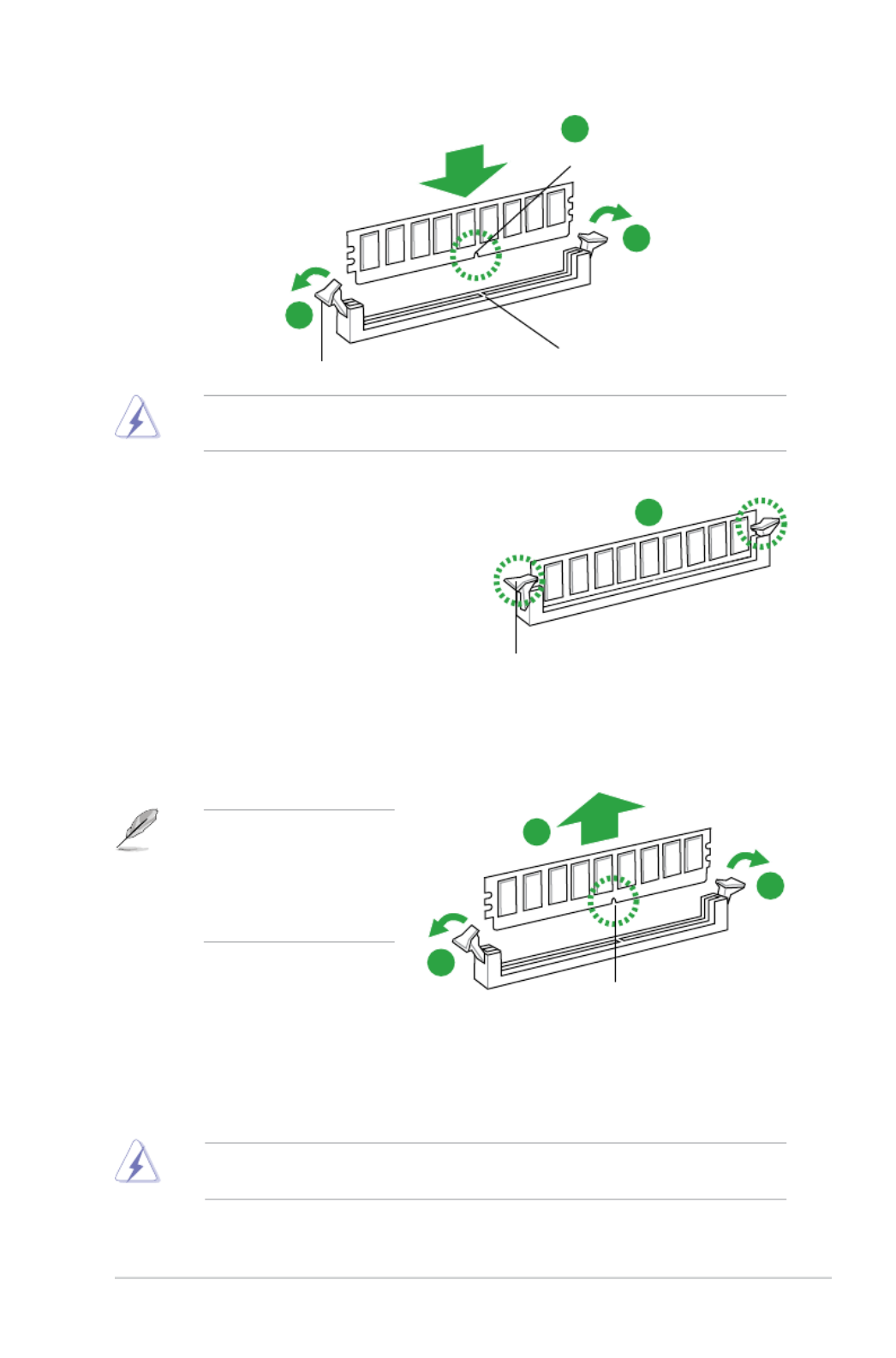
A DIMM is keyed with a notch so that it ts in only one direction. DO NOT force a DIMM into
a socket in the wrong direction to avoid damaging the DIMM.
3. Firmly insert the DIMM into the socket
until the retaining clips snap back
in place and the DIMM is properly
seated.
1.4.4 Removing a DIMM
To remove a DIMM:
1. Simultaneously press the retaining clips outward to unlock the DIMM.
2. Remove the DIMM from the socket.
Support the DIMM lightly
with your ngers when
pressing the retaining
clips. The DIMM might get
damaged when it ips out
with extra force.
1.5 Expansion slots
In the future, you may need to install expansion cards. The following sub-sections describe
the slots and the expansion cards that they support.
Unplug the power cord before adding or removing expansion cards. Failure to do so may
cause you physical injury and damage motherboard components.
Locked Retaining Clip
3
DIMM notch
1
1
2
Unlocked retaining clip
1
DIMM notch
2
1
DIMM slot key

1-10 Chapter 1: Product introduction
1.5.1 Installing an expansion card
To install an expansion card:
1. Before installing the expansion card, read the documentation that came with it and
make the necessary hardware settings for the card.
2. Remove the system unit cover (if your motherboard is already installed in a chassis).
3. Remove the bracket opposite the slot that you intend to use. Keep the screw for later
use.
4. Align the card connector with the slot and press rmly until the card is completely
seated on the slot.
5. Secure the card to the chassis with the screw you removed earlier.
6. Replace the system cover.
1.5.2 Conguring an expansion card
After installing the expansion card, congure it by adjusting the software settings.
1. Turn on the system and change the necessary BIOS settings, if any. See Chapter 2 for
information on BIOS setup.
2. Assign an IRQ to the card.
3. Install the software drivers for the expansion card.
When using PCI cards on shared slots, ensure that the drivers support “Share IRQ” or that
the cards do not need IRQ assignments. Otherwise, conicts will arise between the two PCI
groups, making the system unstable and the card inoperable.
1.5.3 PCI Express p18-x1 slots
This motherboard supports two PCI Express p18-x1 network cards, SCSI cards, and other cards
that comply with the PCI Express specications.
1.5.4 PCI Express x16 slot
This motherboard supports one PCI Express x16 graphics card that complies with the PCI
Express specications.
IRQ assignments for this motherboard
A B C D E F G H
PCIe x16 shared - - - - - - -
Intel I217 (LAN) - - - - shared - - -
On Chip SATA - - - shared - - - -
On Chip USB EHCI 1/2 - - - - shared - - -
On Chip USB XHCI - - - - - shared - -
HD Audio - - - - - - shared -
ASUS H81M Series 1-11
1.6 Jumpers
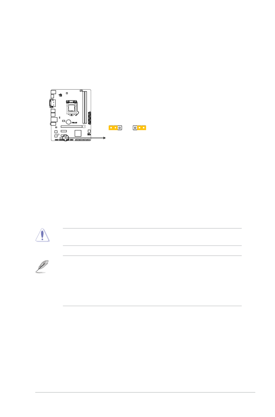
1. Clear RTC RAM (3-pin CLRTC)
This jumper allows you to clear the Real Time Clock (RTC) RAM in CMOS. You can
clear the CMOS memory of date, time, and system setup parameters by erasing
the CMOS RTC RAM data. The onboard button cell battery powers the RAM data in
CMOS, which include system setup information such as system passwords.
H81M-A
H81M-A Clear RTC RAM
1 2 2 3
Normal
(Default)
Clear RTC
CLRTC
To erase the RTC RAM:
1. Turn OFF the computer and unplug the power cord.
2. Move the jumper cap from pins 1-2 (default) to pins 2-3. Keep the cap on pins 2-3
for about 5-10 seconds, then move the cap back to pins 1-2.
3. Plug the power cord and turn ON the computer.
4. Hold down the <Del> key during the boot process and enter BIOS setup to re-
enter data.
Except when clearing the RTC RAM, never remove the cap on CLRTC jumper default
position. Removing the cap will cause system boot failure!
• If the steps above do not help, remove the onboard battery and move the jumper
again to clear the CMOS RTC RAM data. After clearing the CMOS, reinstall the
battery.
• You do not need to clear the RTC when the system hangs due to overclocking. For
system failure due to overclocking, use the CPU Parameter Recall (C.P.R.) feature.
Shut down and reboot the system, then the BIOS automatically resets parameter
settings to default values.

1-12 Chapter 1: Product introduction
H81M-A
1 2
2 3
+5V +5VSB
(Default)
KB_USBPWB
H81M-A Keyboard and USB device wake up
H81M-A
21 2 3
+5V
(Default)
+5VSB
USBPWF
H81M-A USB Device Wake Up
3. USB device wake-up (3-pin USBPWF)
Set this jumper to +5V to wake up the computer from S1 sleep mode (CPU stopped,
DRAM refreshed, system running in low power mode) using the connected USB
devices. Set to +5VSB to wake up from S3 and S4 sleep modes (no power to CPU,
DRAM in slow refresh, power supply in reduced power mode).
2. Keyboard & USB device wake-up (3-pin KB_USBPWB)
Set this jumper to +5V to wake up the computer from S1 sleep mode (CPU stopped,
DRAM refreshed, system running in low power mode) using the connected USB
devices. Set to +5VSB to wake up from S3 and S4 sleep modes (no power to CPU,
DRAM in slow refresh, power supply in reduced power mode).
• The USB device wake-up feature requires a power supply that can provide 500mA on
the +5VSB lead for each USB port; otherwise the system would not power up.
• The total current consumed must NOT exceed the power supply capability (+5VSB)
whether under normal conditions or in sleep mode.
ASUS H81M Series 1-13
1.7 Connectors
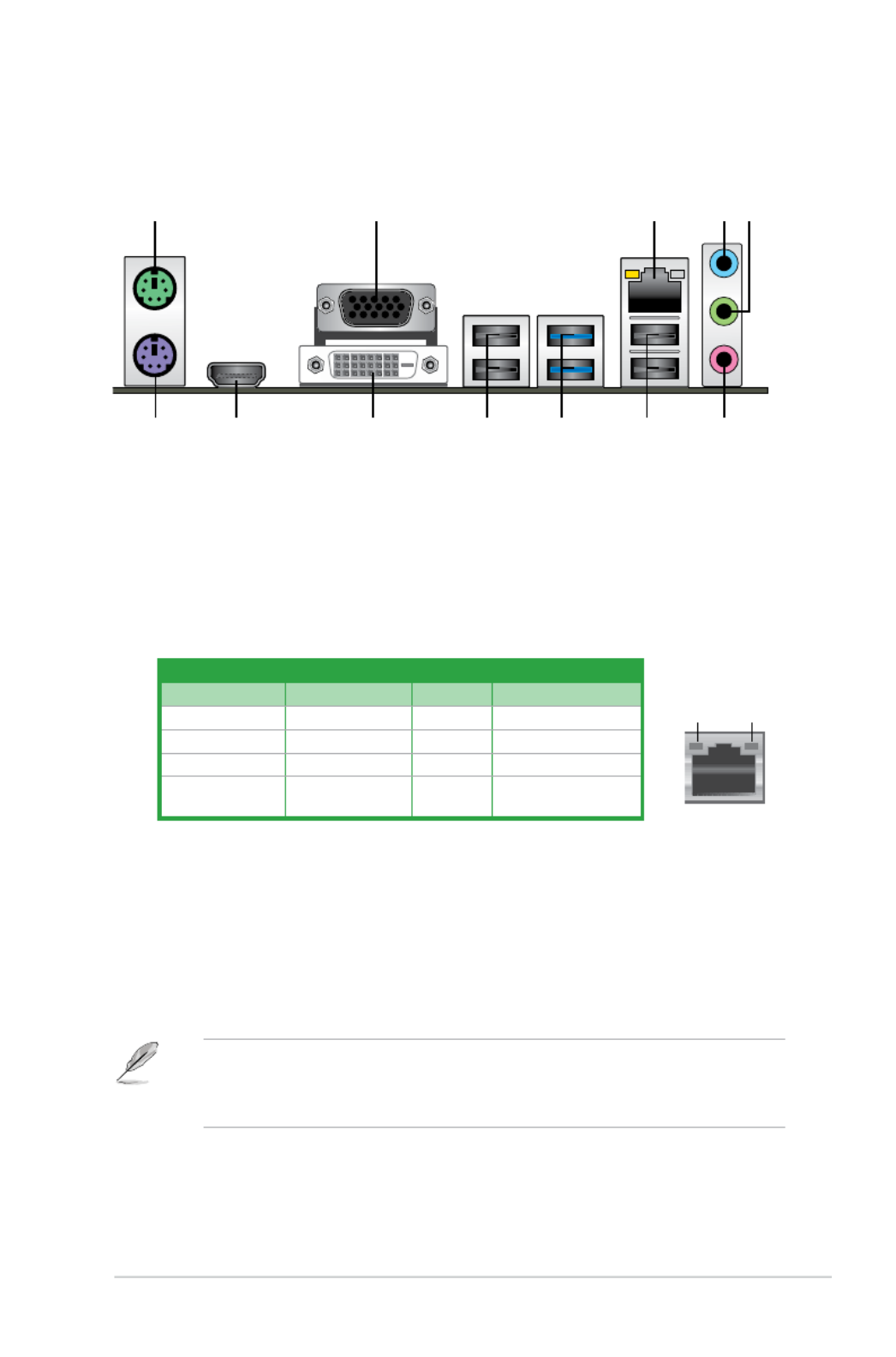
1.7.1 Rear panel connectors
1. PS/2 Mouse port (green). This port is for a PS/2 mouse.
2. Video Graphics Adapter (VGA) port. This 15-pin port is for a VGA monitor or other
VGA-compatible devices.
3. LAN (RJ-45) port. This port allows Gigabit connection to a Local Area Network (LAN)
through a network hub. Refer to the table below for the LAN port LED indications.
3
9 8 7
2
1011
4 5
6
1
12
LAN port
Speed
LED
Activity Link
LED
LAN port LED indications
4. Line In port (light blue). This port connects the tape, CD, DVD player, or other audio
sources.
5. Line Out port (lime). This port connects a headphone or a speaker. In 4-channel, 6-
channel, and 8-channel congurations, the function of this port becomes Front Speaker
Out.
6. Microphone port (pink). This port connects a microphone.
To congure an 8-channel audio output:
Use a chassis with HD audio module in the front panel to support an 8-channel audio
output.
Activity/Link LED Speed LED
Status Description Status Description
Off No link OFF 10Mbps connection
Orange Linked ORANGE 100Mbps connection
Orange (Blinking) Data activity GREEN 1Gbps connection
Orange (Blinking
then steady)
Ready to wake
up from S5 mode

1-14 Chapter 1: Product introduction
7. USB 2.0 ports 3 and 4. These two 4-pin Universal Serial Bus (USB) ports are for USB
2.0/1.1 devices.
8. USB 3.0 ports 1 and 2.
These two 9-pin Universal Serial Bus (USB) ports connect to
USB 3.0/2.0 devices.
• Due to USB 3.0 controller limitations, USB 3.0 devices can only be used under a
Windows® OS environment and after USB 3.0 driver installation.
• The plugged USB 3.0 device may run on xHCI or EHCI mode, depending on the
operating system’s setting.
• USB 3.0 devices can only be used for data storage.
• We strongly recommend that you connect USB 3.0 devices to USB 3.0 ports for faster
and better performance from your USB 3.0 devices.
9. USB 2.0 ports 5 and 6. These two 4-pin Universal Serial Bus (USB) ports are for USB
2.0/1.1 devices.
10. DVI-D port. This port is for any DVI-D compatible device. DVI-D can’t be converted to
output RGB Signal to CRT and isn’t compatible with DVI-I.
11. HDMI port (H81M-A model only). This port is for a High-Denition Multimedia
Interface (HDMI) connector, and is HDCP compliant allowing playback of HD DVD,
Blu-ray, and other protected content.
12. PS/2 keyboard port (purple).
This port is for a PS/2 keyboard.
Audio 2, 4, 6, or 8-channel conguration
Port Headset
2-channel 4-channel 6-channel 8-channel
Light Blue (Rear panel) Line In Rear Speaker Out Rear Speaker Out Rear Speaker Out
Lime (Rear panel) Line Out Front Speaker Out Front Speaker Out Front Speaker Out
Pink (Rear panel) Mic In Mic In Bass/Center Bass/Center
Lime (Front panel) - - - Side Speaker Out

ASUS H81M Series 1-15
1.7.2 Internal connectors
1. Front panel audio connector (10-1 pin AAFP)
This connector is for a chassis-mounted front panel audio I/O module that supports
either HD Audio or legacy AC`97 audio standard. Connect one end of the front panel
audio I/O module cable to this connector.
• We recommend that you connect a high-denition front panel audio module to this
connector to avail of the motherboard’s high-denition audio capability.
• If you want to connect a high-denition front panel audio module to this connector, set
the Front Panel Type item in the BIOS setup to [HD]. If you want to connect an AC’97
front panel audio module to this connector, set the item to [AC97]. By default, this
connector is set to [HD].
H81M-A
H81M-A Front panel audio connector
AAFP
PIN 1
AGND
NC
SENSE1_RETUR
SENSE2_RETUR
PORT1 L
PORT1 R
PORT2 R
SENSE_SEND
PORT2 L
HD-audio-compliant
pin definition
PIN 1
AGND
NC
NC
NC
MIC2
MICPWR
Line out_R
NC
Line out_L
Legacy AC’97
compliant definition
The S/PDIF module is purchased separately.
2. Digital audio connector (4-1 pin SPDIF_OUT)
This connector is for an additional Sony/Philips Digital Interface (S/PDIF) port. Connect
the S/PDIF Out module cable to this connector, then install the module to a slot
opening at the back of the system chassis.
H81M-A
H81M-A Digital audio connector
SPDIF_OUT
+5V
SPDIFOUT
GND

1-16 Chapter 1: Product introduction
3. CPU and chassis fan connectors (4-pin CPU_FAN, 4-pin CHA_FAN)
Connect the fan cables to the fan connectors on the motherboard, ensuring that the
black wire of each cable matches the ground pin of the connector.
Do not forget to connect the fan cables to the fan connectors. Insufcient air ow inside
the system may damage the motherboard components. These are not jumpers! Do not
place jumper caps on the fan connectors! The CPU_FAN connector supports a CPU fan of
maximum 1A (12 W) fan power.
CPU_FAN
CPU FAN PWM
CPU FAN IN
CPU FAN PWR
GND
H81M-A
H81M-A CPU fan connector
CHA_FAN
CHA FAN PWM
CHA FAN IN
CHA FAN PWR
GND
4. USB 2.0 connectors (10-1 pin USB910, USB1112)
These connectors are for USB 2.0 ports. Connect the USB module cable to any of
these connectors, then install the module to a slot opening at the back of the system
chassis. These USB connectors comply with USB 2.0 specications and supports up to
480Mbps connection speed.
Never connect a 1394 cable to the USB connectors. Doing so will damage the
motherboard!
The USB 2.0 module is purchased separately.
H81M-A
USB910
PIN 1
USB+5V
USB_P10-
USB_P10+
GND
NC
USB+5V
USB_P9-
USB_P9+
GND
USB1112
PIN 1
USB+5V
USB_P12-
USB_P12+
GND
NC
USB+5V
USB_P11-
USB_P11+
GND
H81M-A USB2.0 connectors
Only the 4-pin CPU fan and chassis fan support the ASUS Fan Xpert feature.

1-18 Chapter 1: Product introduction
SATA3G_1
GND
RSATA_RXP1
RSATA_RXN1
GND
RSATA_TXN1
RSATA_TXP1
GND
SATA3G_2
GND
RSATA_RXP2
RSATA_RXN2
GND
RSATA_TXN2
RSATA_TXP2
GND
H81M-A
H81M-A SATA 3.0Gb/s connectors
7. Intel® H81 Serial ATA 3.0 Gb/s connectors (7-pin SATA3G 1~2 [brown])
These connectors connect to Serial ATA 3.0 Gb/s hard disk drives via Serial ATA 3.0
Gb/s signal cables.
8. Intel® H81 Serial ATA 6.0Gb/s connectors (7-pin SATA6G_1~2 [yellow])
These connectors connect to Serial ATA 6.0 Gb/s hard disk drives via Serial ATA 6.0
Gb/s signal cables.
When using hot-plug and NCQ, set the SATA Mode Selection item in the BIOS to [AHCI].
SATA6G_1
GND
RSATA_RXP1
RSATA_RXN1
GND
RSATA_TXN1
RSATA_TXP1
GND
SATA6G_2
GND
RSATA_RXP2
RSATA_RXN2
GND
RSATA_TXN2
RSATA_TXP2
GND
H81M-A
H81M-A SATA 6.0Gb/s connectors
•
You must install Windows XP Service Pack 3 or later version before using Serial ATA
hard disk drives.
•
When using hot-plug and NCQ, set the SATA Mode Selection item in the BIOS to
[AHCI].

1-20 Chapter 1: Product introduction
1.8 Onboard LEDs
1. Standby Power LED
The motherboard comes with a standby power LED that lights up to indicate that the
system is ON, in sleep mode, or in soft-off mode. This is a reminder that you should
shut down the system and unplug the power cable before removing or plugging in any
motherboard component. The illustration below shows the location of the onboard LED.
SB_PWR
ON
Standby Power Powered Off
OFF
H81M-A
H81M-A Onboard LED

ASUS H81M Series 1-21
1.9 Software support
1.9.1 Installing an operating system
This motherboard supports Windows
® 7 (32bit/64bit) and Windows
® 8 (32bit/64bit) Operating
Systems (OS). Always install the latest OS version and corresponding updates to maximize
the features of your hardware.
Motherboard settings and hardware options vary. Refer to your OS documentation for
detailed information.
1.9.2 Support DVD information
The Support DVD that comes with the motherboard package contains the drivers, software
applications, and utilities that you can install to avail all motherboard features.
The contents of the Support DVD are subject to change at any time without notice. Visit the
ASUS website at www.asus.com for updates.
The following screen is for reference only.
To run the Support DVD
Place the Support DVD into the optical drive. If Autorun is enabled in your computer, the
DVD automatically displays the Specials screen which lists the unique features of your ASUS
motherboard. Click Drivers, Utilities, AHCI Driver, Manual, Contact and Specials tabs to
display their respective menus.
Click an item to install
Click an icon to
display Support
DVD/motherboard
information
If Autorun is NOT enabled in your computer, browse the contents of the Support DVD to
locate the le ASSETUP.EXE from the BIN folder. Double-click the ASSETUP.EXE to run
the DVD.
Click to display more items

1-22 Chapter 1: Product introduction

2-2 Chapter 2: Getting started
2.1.2 ASUS EZ Flash 2
The ASUS EZ Flash 2 feature allows you to update the BIOS without using an OS-based
utility.
Before you start using this utility, download the latest BIOS le from the ASUS website at
www.asus.com.
To update the BIOS using EZ Flash 2:
1. Insert the USB ash disk that contains the latest BIOS le to the USB port.
2. Enter the Advanced Mode Tool of the BIOS setup program. Go to the menu to select
ASUS EZ Flash 2 Utility and press <Enter> to enable it.
3. Press <Tab> to switch to the
Drive eld.
4. Press the Up/Down arrow keys to nd the USB ash disk that contains the latest BIOS,
and then press <Enter>.
5. Press <Tab> to switch to the
Folder Info eld.
6. Press the Up/Down arrow keys to nd the BIOS le, and then press <Enter> to perform
the BIOS update process. Reboot the system when the update process is done.
• This function supports USB ash disks formatted using FAT32/16 on a single partition
only.
• Ensure to load the BIOS default settings to ensure system compatibility and stability.
Select the Load Optimized Defaults item under the Exit menu. .
• DO NOT shut down or reset the system while updating the BIOS to prevent system
boot failure!

2-3
ASUS H81M Series
2.1.3 ASUS CrashFree BIOS 3 utility
The ASUS CrashFree BIOS 3 is an auto recovery tool that allows you to restore the BIOS le
when it fails or gets corrupted during the updating process. You can restore a corrupted BIOS
le using the motherboard support DVD or a USB ash drive that contains the updated BIOS
le.
• Before using this utility, rename the BIOS le in the removable device to H81MA.CAP
(for H81M-A) (for H81M-E)., H81ME.CAP
• The BIOS le in the support DVD may not be the latest version. Download the latest
BIOS le from the ASUS website at www.asus.com.
Recovering the BIOS
To recover the BIOS:
1. Turn on the system.
2. Insert the support DVD to the optical drive or the USB ash drive that contains the
BIOS le to the USB port.
3. The utility automatically checks the devices for the BIOS le. When found, the utility
reads the BIOS le and enters ASUS EZ Flash 2 utility automatically.
4. The system requires you to enter BIOS Setup to recover BIOS setting. To ensure
system compatibility and stability, we recommend that you press <F5> to load default
BIOS values.
DO NOT shut down or reset the system while updating the BIOS! Doing so can cause
system boot failure!
2.1.4 ASUS BIOS Updater
The ASUS BIOS Updater allows you to update BIOS in DOS environment. This utility also
allows you to copy the current BIOS le that you can use as a backup when the BIOS fails or
gets corrupted during the updating process.
The succeeding utility screens are for reference only. The actual utility screen displays may
not be same as shown.
Before updating BIOS
1. Prepare the motherboard support DVD and a USB ash drive in FAT32/16 format and
single partition.
2. Download the latest BIOS le and BIOS Updater from the ASUS website at
http://support.asus.com and save them on the USB ash drive.
NTFS is not supported under DOS environment. Do not save the BIOS le and BIOS
Updater to a hard disk drive or USB ash drive in NTFS format.
3. Turn off the computer and disconnect all SATA hard disk drives (optional).

2-4 Chapter 2: Getting started
3. Select the USB ash drive as the bootdevice. The DOS screen appears.
Updating the BIOS le
To update the BIOS le using BIOS Updater:
1. At the FreeDOS prompt, type
bupdater /pc /g and press <Enter>.
2. The BIOS Updater screen appears as below.
ASUSTek BIOS Updater for DOS V1.30
BOARD: H81M-A
VER: 0209
DATE: 06/03/2013
H81MA.CAP 4194304 2013-06-07 17:30:48
Booting the system in DOS environment
1. Insert the DOS-bootable USB ash drive with the latest BIOS le and BIOS Updater to
your computer’s USB port.
2. Boot your computer. When the ASUS Logo appears, press <F8> to show the
BIOS
Boot Device Menu.
Product specificaties
| Merk: | Asus |
| Categorie: | Moederbord |
| Model: | H81M-E |
| Breedte: | 226 mm |
| Diepte: | 175 mm |
| Ethernet LAN: | Ja |
| Maximum resolutie: | 1920 x 1200 Pixels |
| Type stroombron: | ATX |
| Meegeleverde kabels: | SATA |
| Aantal USB 2.0-poorten: | 4 |
| VGA (D-Sub)poort(en): | 1 |
| Microfoon, line-in ingang: | Ja |
| Aantal Ethernet LAN (RJ-45)-poorten: | 1 |
| Hoofdtelefoonuitgangen: | 1 |
| DVI-D poorten: | 1 |
| Aantal poorten USB 3.2 Gen 1 (3.1 Gen 1) Type A: | 2 |
| Processor socket: | LGA 1150 (Socket H3) |
| Processorfabrikant: | Intel |
| Maximum intern geheugen: | 16 GB |
| Audio-uitgangskanalen: | - kanalen |
| Snelle installatiehandleiding: | Ja |
| Ethernet interface type: | Gigabit Ethernet |
| Chipset moederbord: | Intel® H81 |
| Geheugen slots type: | DIMM |
| Audiochip: | Realtek ALC887 |
| Meegeleverde drivers: | Ja |
| PCI Express x16 slots: | 1 |
| Grafische adapter-familie: | Intel |
| S/PDIF-uitgang: | Ja |
| Type koeling: | Passief |
| Geheugen kanaal: | Dual-channel |
| Ondersteunde opslagstationinterfaces: | SATA II,SATA III |
| PS/2 poort(en): | 2 |
| Component voor: | PC |
| Maximum geheugen grafische adapter: | 1024 MB |
| Aantal SATA III connectors: | 2 |
| Non-ECC: | Ja |
| Compatibele processors: | Intel Celeron,Intel Pentium |
| Ondersteunde geheugen types: | DDR3-SDRAM |
| PCI Express x1 (Gen 2.x) slots: | 2 |
| Moederbord chipset familie: | Intel |
| Supported memory clock speeds: | 1066,1333,1600 MHz |
| BIOS type: | UEFI AMI |
| ACPI version: | 2.0a |
| Ondersteuning voor parallel processing: | Niet ondersteund |
| Aansluiting voor CPU koeler: | Ja |
| Aansluitingen voor behuizingsventilatoren: | 1 |
| ATX Power connector (24-pin): | Ja |
| Aansluiting voor ventilator van voeding: | Ja |
| Aantal SATA-aansluitingen: | 4 |
| USB 2.0 aansluitingen: | 4 |
| Aansluiting voor audiopaneel aan voorzijde: | Ja |
| Chassis intrusion aansluiting: | Ja |
| Aantal SATA II connectors: | 2 |
| Peripheral (Molex) power connectors (4-pin): | 1 |
| Ondersteunde geheugenmodule capaciteiten: | 1GB,2GB,4GB,8GB |
| Clear CMOS jumper: | Ja |
| S/PDIF in connector: | Ja |
Heb je hulp nodig?
Als je hulp nodig hebt met Asus H81M-E stel dan hieronder een vraag en andere gebruikers zullen je antwoorden
Handleiding Moederbord Asus

27 Maart 2025
27 Maart 2025
12 Februari 2025
12 Februari 2025
12 Februari 2025
12 Februari 2025
18 December 2024
18 December 2024
18 December 2024
18 December 2024
Handleiding Moederbord
- Moederbord Asrock
- Moederbord EPoX
- Moederbord Evga
- Moederbord Gigabyte
- Moederbord MSI
- Moederbord Sharkoon
- Moederbord NZXT
- Moederbord Intel
- Moederbord Supermicro
- Moederbord ECS
- Moederbord Foxconn
- Moederbord Advantech
- Moederbord Elitegroup
- Moederbord Biostar
Nieuwste handleidingen voor Moederbord

29 Maart 2025

24 Maart 2025

10 Maart 2025

4 Maart 2025
12 Februari 2025
12 Februari 2025
12 Februari 2025
12 Februari 2025
12 Februari 2025
11 Februari 2025