Asrock H470M-HVS R2.0 Handleiding
Asrock
Moederbord
H470M-HVS R2.0
Lees hieronder de 📖 handleiding in het Nederlandse voor Asrock H470M-HVS R2.0 (72 pagina's) in de categorie Moederbord. Deze handleiding was nuttig voor 24 personen en werd door 2 gebruikers gemiddeld met 4.5 sterren beoordeeld
Pagina 1/72


Contact Information
If you need to contact ASRock or want to know more about ASRock, you’re
welcome to visit ASRock’s website at http://www.asrock.com; or you may contact
your dealer for further information. For technical questions, please submit a
support request form at https://event.asrock.com/tsd.asp
ASRock Incorporation
e-mail: info@asrock.com.tw
ASRock EUROPE B.V.
e-mail: sales@asrock.nl
ASRock America, Inc.
e-mail: sales@asrockamerica.com
Scan the QR code to view more manuals and documents.

Contents
Chapter 1 Introduction 1
1.1 Package Contents 1
1.2 Specications 2
1.3 Motherboard Layout 6
1.4 I/O Panel 8
Chapter 2 Installation 9
2.1 Installing the CPU 10
2.2 Installing the CPU Fan and Heatsink 13
2.3 Installing Memory Modules (DIMM) 14
2.4 Expansion Slots (PCI Express Slots) 16
2.5 Jumpers Setup 17
2.6 Onboard Headers and Connectors 18
Chapter 3 Software and Utilities Operation 22
3.1 Installing Drivers 22
3.2 ASRock Motherboard Utility (A-Tuning) 23
3.2.1 Installing ASRock Motherboard Utility (A-Tuning) 23
3.2.2 Using ASRock Motherboard Utility (A-Tuning) 23
3.3 ASRock Live Update & APP Shop 26
3.3.1 UI Overview 26
3.3.2 Apps 27
3.3.3 BIOS & Drivers 30
3.3.4 Setting 31

Chapter 4 UEFI SETUP UTILITY 32
4.1 Introduction 32
4.2 EZ Mode 33
4.3 Advanced Mode 34
4.3.1 UEFI Menu Bar 34
4.3.2 Navigation Keys 35
4.4 Main Screen 36
4.5 OC Tweaker Screen 37
4.6 Advanced Screen 45
4.6.1 CPU Conguration 46
4.6.2 Chipset Conguration 48
4.6.3 Storage Conguration 51
4.6.4 Super IO Conguration 52
4.6.5 ACPI Conguration 53
4.6.6 USB Conguration 54
4.6.7 Trusted Computing 55
4.7 Tools 56
4.8 Hardware Health Event Monitoring Screen 58
4.9 Security Screen 60
4.10 Boot Screen 61
4.11 Exit Screen 64

English
1
H470M-HVS R2.0
Chapter 1 Introduction
ank you for purchasing ASRock H470M-HVS R2.0 motherboard, a reliable
motherboard produced under ASRock’s consistently stringent quality control.
It delivers excellent performance with robust design conforming to ASRock’s
commitment to quality and endurance.
In this documentation, Chapter 1 and 2 contains the introduction of the
motherboard and step-by-step installation guides. Chapter 3 contains the operation
guide of the soware and utilities. Chapter 4 contains the conguration guide of
the BIOS setup.
1.1 Package Contents
ASRock H470M-HVS R2.0 Motherboard (Micro ATX Form Factor)
ASRock H470M-HVS R2.0 User Manual
ASRock H470M-HVS R2.0 Support CD
2 x Serial ATA (SATA) Data Cables (Optional)
1 x I/O Panel Shield
Because the motherboard specications and the BIOS soware might be updated, the
content of this documentation will be subject to change without notice. In case any
modications of this documentation occur, the updated version will be available on
ASRock’s website without further notice. If you require technical support related to
this motherboard, please visit our website for specic information about the model
you are using. You may nd the latest VGA cards and CPU support list on ASRock’s
website as well. ASRock website http://www.asrock.com.

English
2
1.2 Specications
Platform Micro ATX Form Factor
Solid Capacitor design
CPU Supports 10th Gen Intel® CoreTM Processors (Socket 1200)
Digi Power design
5 Power Phase design
Supports Intel® Turbo Boost Max 3.0 Technology
Chipset Intel® H470
Memory Dual Channel DDR4 Memory Technology
2 x DDR4 DIMM Slots
Supports DDR4 2933/2800/2666/2400/2133 non-ECC, un-
buered memory
* Please refer to Memory Support List on ASRock's website for
more information. (http://www.asrock.com/)
* CoreTM (i9/i7) support DDR4 up to 2933; CoreTM (i5/i3),
Pentium® and Celeron® support DDR4 up to 2666.
Supports ECC UDIMM memory modules (operate in non-
ECC mode)
Max. capacity of system memory: 64GB
Supports Intel® Extreme Memory Prole (XMP) 2.0
15μ Gold Contact in DIMM Slots
Expansion
Slot
1 x PCI Express 3.0 x16 Slot
* Supports NVMe SSD as boot disks
1 x PCI Express 3.0 p6-x1 Slot
Graphics Intel® UHD Graphics Built-in Visuals and the VGA outputs
can be supported only with processors which are GPU
integrated.
Hardware Accelerated Codecs: AVC/H.264, HEVC/H.265
8bit, HEVC/H.265 10bit, VP8, VP9 8bit, VP9 10bit, MPEG 2,
MJPEG, VC-1
* VP9 10bit and VC-1 are for decode only.
* VP8 and VP9 encode are not supported by Windows OS.
English
3
H470M-HVS R2.0
Graphics, Media & Compute: Microso DirectX 12,
OpenGL 4.5, Intel® Built In Visuals, Intel® Quick Sync
Video, Hybrid / Switchable Graphics, OpenCL 2.1
Display & Content Security: Rec. 2020 (Wide Color Gamut),
Microso PlayReady 3.0, Intel® SGX Content Protection,
UHD/HDR Blu-ray Disc
Dual graphics output: support HDMI and D-Sub ports by
independent display controllers
Supports HDMI 1.4 with max. resolution up to 4K x 2K
(4096x2160) @ 30Hz
Supports D-Sub with max. resolution up to 1920x1200 @
60Hz
Supports Auto Lip Sync, Deep Color (12bpc), xvYCC and
HBR (High Bit Rate Audio) with HDMI 1.4 Port (Compliant
HDMI monitor is required)
Supports HDCP 2.3 with HDMI 1.4 Port
Supports 4K Ultra HD (UHD) playback with HDMI 1.4 Port
Audio 7.1 CH HD Audio (Realtek ALC897 Audio Codec)
Supports Surge Protection
LAN PCIE p7-x1 Gigabit LAN 10/100/1000 Mb/s
Realtek RTL8111H
Supports Wake-On-LAN
Supports Lightning/ESD Protection
Supports Energy Ecient Ethernet 802.3az
Supports PXE
Rear Panel
I/O
1 x PS/2 Mouse/Keyboard Port
4 x USB 2.0 Ports (Supports ESD Protection)
2 x USB 3.2 Gen1 Ports (Supports ESD Protection)
1 x RJ-45 LAN Port with LED (ACT/LINK LED and SPEED
LED)
HD Audio Jacks: Line in / Front Speaker / Microphone
1 x D-Sub Port
1 x HDMI Port

English
4
Storage 4 x SATA3 6.0 Gb/s Connectors, support RAID (RAID 0,
RAID 1, RAID 5, RAID 10, Intel Rapid Storage Technology
17), NCQ, AHCI and Hot Plug
Connector 1 x SPI TPM Header
1 x Chassis Intrusion and Speaker Header
1 x CPU Fan Connector (4-pin)
* e CPU Fan Connector supports the CPU fan of maximum
1A (12W) fan power.
1 x Chassis/Water Pump Fan Connector (4-pin) (Smart Fan
Speed Control)
* e Chassis/Water Pump Fan supports the water cooler fan of
maximum 2A (24W) fan power.
* CHA_FAN1/WP can auto detect if 3-pin or 4-pin fan is in
use.
1 x 24 pin ATX Power Connector
1 x 8 pin 12V Power Connector
1 x Front Panel Audio Connector
1 x USB 2.0 Header (Supports 2 USB 2.0 ports) (Supports
ESD Protection)
1 x USB 3.2 Gen1 Header (Supports 2 USB 3.2 Gen1 ports)
(Supports ESD Protection)
BIOS
Feature
AMI UEFI Legal BIOS with multilingual GUI support
ACPI 6.0 Compliant wake up events
SMBIOS 2.7 Support
CPU Core/Cache, GT, DRAM, PCH +1.0V, VCCST Voltage
Multi-adjustment
Hardware
Monitor
Temperature Sensing: CPU, Chassis/Water Pump Fans
Fan Tachometer: CPU, Chassis/Water Pump Fans
Quiet Fan (Auto adjust chassis fan speed by CPU tempera-
ture): CPU, Chassis/Water Pump Fans
Fan Multi-Speed Control: CPU, Chassis/Water Pump Fans
CASE OPEN detection
Voltage monitoring: +12V, +5V, +3.3V, CPU Vcore, PCH
+1.0V
OS Microso® Windows® 10 64-bit / 11 64-bit
English
6
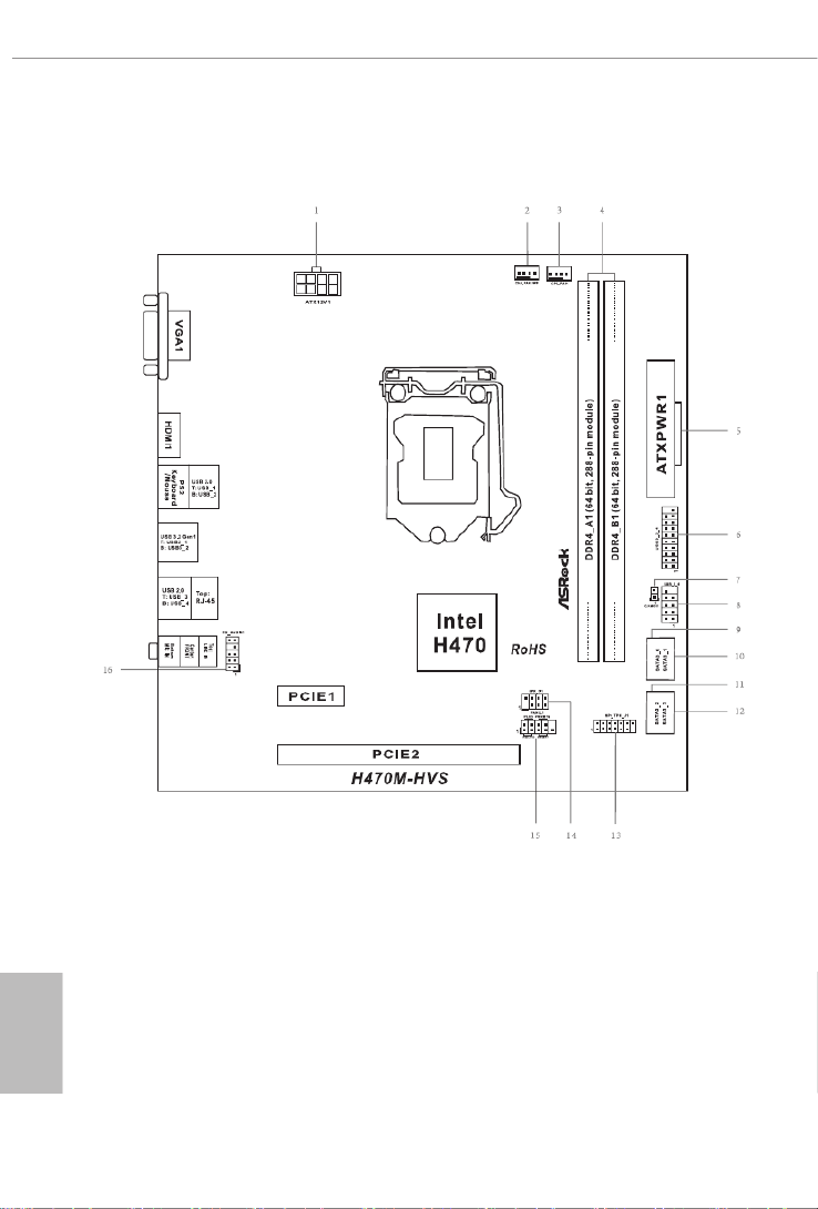
1.3 Motherboard Layout

English
7
H470M-HVS R2.0
No. Description
1 ATX 12V Power Connector (ATX12V1)
2 Chassis/Water Pump Fan Connector (CHA_FAN1/WP)
3 CPU Fan Connector (CPU_FAN1)
4 2 x 288-pin DDR4 DIMM Slots (DDR4_A1, DDR4_B1)
5 ATX Power Connector (ATXPWR1)
6 USB 3.2 Gen1 Header (USB3_3_4)
7 Clear CMOS Jumper (CLRMOS1)
8 USB 2.0 Header (USB_5_6)
9 SATA3 Connector (SATA3_0)
10 SATA3 Connector (SATA3_1)
11 SATA3 Connector (SATA3_2)
12 SATA3 Connector (SATA3_3)
13 SPI TPM Header (SPI_TPM_J1)
14 Chassis Intrusion and Speaker Header (SPK_CI1)
15 System Panel Header (PANEL1)
16 Front Panel Audio Header (HD_AUDIO1)

English
9
H470M-HVS R2.0
is is a Micro ATX form factor motherboard. Before you install the motherboard,
study the conguration of your chassis to ensure that the motherboard ts into it.
Pre-installation Precautions
Take note of the following precautions before you install motherboard components
or change any motherboard settings.
Make sure to unplug the power cord before installing or removing the motherboard
components. Failure to do so may cause physical injuries and damages to motherboard
components.
In order to avoid damage from static electricity to the motherboard’s components,
NEVER place your motherboard directly on a carpet. Also remember to use a
grounded wrist strap or touch a safety grounded object before you handle the
components.
Hold components by the edges and do not touch the ICs.
Whenever you uninstall any components, place them on a grounded anti-static pad or
in the bag that comes with the components.
When placing screws to secure the motherboard to the chassis, please do not over-
tighten the screws! Doing so may damage the motherboard.
Chapter 2 Installation

English
10
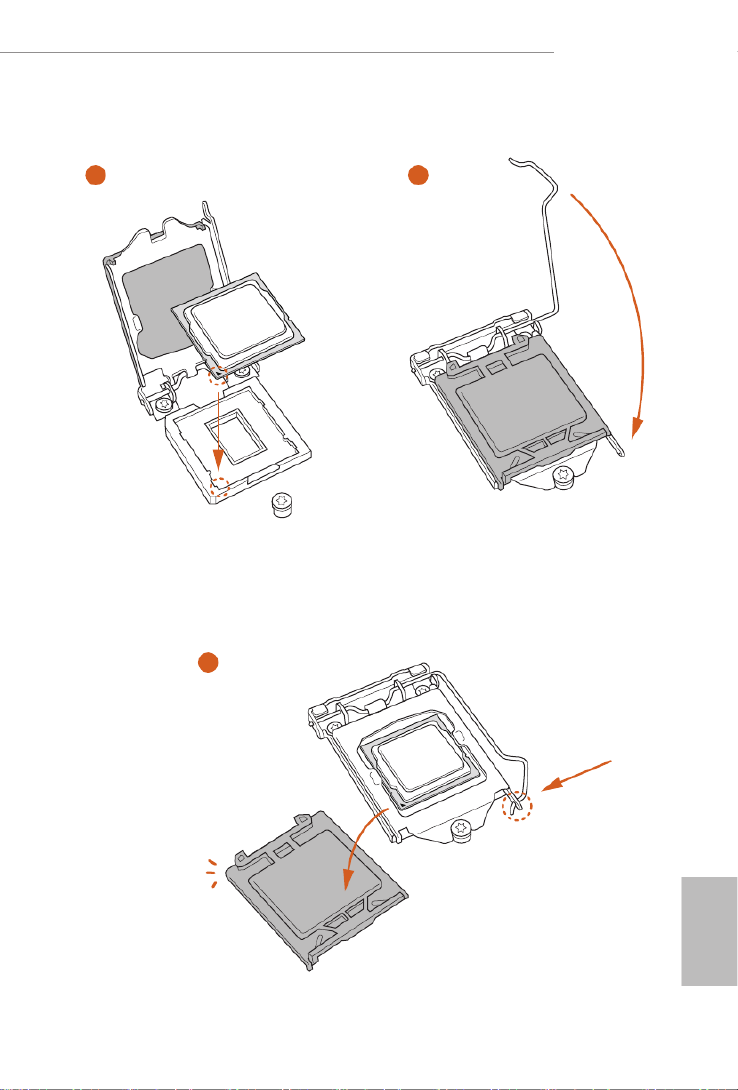
2.1 Installing the CPU
1. Before you insert the 1200-Pin CPU into the socket, please check if the PnP cap
is on the socket, if the CPU surface is unclean, or if there are any in the bent pins
socket. Do not force to insert the CPU into the socket if above situation is found.
Otherwise, the CPU will be seriously damaged.
2. Unplug all power cables before installing the CPU.
1
2
A
B
English
11
H470M-HVS R2.0
4
5
3

English
12
Please save and replace the cover if the processor is removed. e cover must be
placed if you wish to return the motherboard for aer service.

English
13
H470M-HVS R2.0
2.2 Installing the CPU Fan and Heatsink
1 2
CPU_FAN
English
14
2.3 Installing Memory Modules (DIMM)
is motherboard provides two 288-pin DDR4 (Double Data Rate 4) DIMM slots,
and supports Dual Channel Memory Technology.
e DIMM only ts in one correct orientation. It will cause permanent damage to
the motherboard and the DIMM if you force the DIMM into the slot at incorrect
orientation.
1. For dual channel conguration, you always need to install identical (the same
brand, speed, size and chip-type) DDR4 DIMM pairs.
2. It is unable to activate Dual Channel Memory Technology with only one memory
module installed.
3. It is not allowed to install a DDR, DDR2 or DDR3 memory module into a DDR4
slot; otherwise, this motherboard and DIMM may be damaged.

English
15
H470M-HVS R2.0
1
2
3

English
16
2.4 Expansion Slots (PCI Express Slots)
ere are 2 PCI Express slots on the motherboard.
PCIe slots:
PCIE1 (PCIe 3.0 p20-x1 slot) is used for PCI Express p20-x1 lane width cards.
PCIE2 (PCIe 3.0 x16 slot) is used for PCI Express x16 lane width graphics cards.
Before installing an expansion card, please make sure that the power supply is
switched o or the power cord is unplugged. Please read the documentation of the
expansion card and make necessary hardware settings for the card before you start
the installation.

English
17
H470M-HVS R2.0
2.5 Jumpers Setup
e illustration shows how jumpers are setup. When the jumper cap is placed on
the pins, the jumper is “Short”. If no jumper cap is placed on the pins, the jumper is
“Open”.
Clear CMOS Jumper
(CLRMOS1)
(see p.6, No. 7)
Short: Clear CMOS
Open: Default
CLRMOS1 allows you to clear the data in CMOS. e data in CMOS includes
system setup information such as system password, date, time, and system setup
parameters. To clear and reset the system parameters to default setup, please turn
o the computer and unplug the power cord, then use a jumper cap to short the
pins on CLRMOS1 for 3 seconds. Please remember to remove the jumper cap aer
clearing the CMOS. If you need to clear the CMOS when you just nish updating
the BIOS, you must boot up the system rst, and then shut it down before you do
the clear-CMOS action.
2-pin Jumper
If you clear the CMOS, the case open may be detected. Please adjust the BIOS option
“Clear Status” to clear the record of previous chassis intrusion status.
English
19
H470M-HVS R2.0
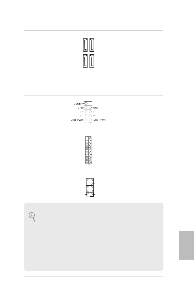
Serial ATA3 Connectors
Right Angle:
(SATA3_0:
see p.6, No. 9)
(SATA3_1:
see p.6, No. 10)
(SATA3_2:
see p.6, No. 11)
(SATA3_3:
see p.6, No. 12)
ese four SATA3
connectors support SATA
data cables for internal
storage devices with up
to 6.0 Gb/s data transfer
rate.
USB 2.0 Header
(9-pin USB_5_6)
(see p.6, No. 8)
ere is one header on
this motherboard. is
USB 2.0 header can
support two ports.
USB 3.2 Gen1 Header
(19-pin USB3_3_4)
(see p.6, No. 6)
ere is one header on
this motherboard. is
USB 3.2 Gen1 header can
support two ports.
Front Panel Audio Header
(9-pin HD_AUDIO1)
(see p.6, No. 16)
is header is for
connecting audio devices
to the front audio panel.
1
In tA _ PB _D +
Du mm y
In tA _ PB _D -
GN D
In tA _ PB _S ST X+
GN D
In tA _ PB _S ST X-
In tA _ PB _S SR X+
In tA _ PB _S SR X-
Vb usVb us
Vb us
In tA _ PA_ SS RX-
In tA _ PA_ SS RX+
GN D
In tA _ PA_ SS TX-
In tA _ PA_ SS TX+
GN D
In tA _PA_ D-
In tA _PA_ D+
SATA3_1
SATA3_0
SATA3_3
SATA3_2
J _S EN S E
O UT 2_ L
M IC _R E T
P RE SE N CE #
G N D
O UT 2_ R
MIC2_ R
MIC2_ L
O UT _R ET
1
1. High Denition Audio supports Jack Sensing, but the panel wire on the chassis
must support HDA to function correctly. Please follow the instructions in our
manual and chassis manual to install your system.
2. If you use an AC’97 audio panel, please install it to the front panel audio header by
the steps below:
A. Connect Mic_IN (MIC) to MIC2_L.
B. Connect Audio_R (RIN) to OUT2_R and Audio_L (LIN) to OUT2_L.
C. Connect Ground (GND) to Ground (GND).
D. MIC_RET and OUT_RET are for the HD audio panel only. You don’t need to
connect them for the AC’97 audio panel.
E. To activate the front mic, go to the “FrontMic” Tab in the Realtek Control panel
and adjust “Recording Volume”.

English
20
GND
FAN _V OLTA GE_C ON TR OL
FAN _S PE ED
FAN _S PE ED_C ON TR OL
Chassis/Water Pump Fan
Connector
(4-pin CHA_FAN1/WP)
(see p.6, No. 2)
is motherboard provides one
4-Pin water cooling
chassis
fan
connector. If you plan to connect
a 3-Pin
chassis
water cooler fan,
please connect it to Pin 1-3.
CPU Fan Connector
(4-pin CPU_FAN1)
(see p.6, No. 3)
is motherboard
provides a 4-Pin CPU fan
(Quiet Fan) connector.
If you plan to connect a
3-Pin CPU fan, please
connect it to Pin 1-3.
ATX Power Connector
(24-pin ATXPWR1)
(see p.6, No. 5)
is motherboard pro-
vides a 24-pin ATX power
connector. To use a 20-
pin ATX power supply,
please plug it along Pin 1
and Pin 13.
ATX 12V Power
Connector
(8-pin ATX12V1)
(see p.6, No. 1)
is motherboard
provides a 8-pin ATX 12V
power connector. To use a
4-pin ATX power supply,
please plug it along Pin 1
and Pin 5.
*Warning: Please make
sure that the power cable
connected is for the CPU
and not the graphics
card. Do not plug the
PCIe power cable to this
connector.
12
1
24
13
4 1
8 5
GND
+12V
CPU_FAN_SPEED
FA N_ SPE ED_C ONT R OL
1 2 3 4

English
21
H470M-HVS R2.0
SPI TPM Header
(13-pin SPI_TPM_J1)
(see p.6, No. 13)
is connector supports SPI
Trusted Platform Module (TPM)
system, which can securely store
keys, digital certicates, pass-
words, and data. A TPM system
also helps enhance network
security, protects digital
identities, and ensures platform
integrity.
1
SPI_DQ 3
+3. 3 V
SPI_DQ 2
SPI_CS 0
Dumm y
CLK
SPI_MIS O
SPI_MOS I
GND
SPI_TPM_CS #
RST#
RSMRST #
TP M_PIRQ

English
22
Chapter 3 Software and Utilities Operation
3.1 Installing Drivers
e Support CD that comes with the motherboard contains necessary drivers and
useful utilities that enhance the motherboard’s features.
Running The Support CD
To begin using the support CD, insert the CD into your CD-ROM drive. e CD
automatically displays the Main Menu if “AUTORUN” is enabled in your computer.
If the Main Menu does not appear automatically, locate and double click on the le
“ASRSETUP.EXE” in the Support CD to display the menu.
Drivers Menu
e drivers compatible to your system will be auto-detected and listed on the
support CD driver page. Please click or follow the order from top to Install All
bottom to install those required drivers. erefore, the drivers you install can work
properly.
Utilities Menu
e Utilities Menu shows the application soware that the motherboard supports.
Click on a specic item then follow the installation wizard to install it.

English
23
H470M-HVS R2.0
3.2 ASRock Motherboard Utility (A-Tuning)
ASRock Motherboard Utility (A-Tuning) is ASRock’s multi purpose soware suite
with a new interface, more new features and improved utilities.
3.2.1 Installing ASRock Motherboard Utility (A-Tuning)
ASRock Motherboard Utility (A-Tuning) can be downloaded from ASRock Live
Update & APP Shop. Aer the installation, you will nd the icon “ASRock Mother-
board Utility (A-Tuning)“ on your desktop. Double-click the
“ASRock Motherboard Utility (A-Tuning)“ icon, ASRock Motherboard Utility
(A-Tuning) main menu will pop up.
3.2.2 Using ASRock Motherboard Utility (A-Tuning)
ere are four sections in ASRock Motherboard Utility (A-Tuning) main menu:
Operation Mode, System Info, FAN-Tastic Tuning and Settings.
Operation Mode
Choose an operation mode for your computer.

English
24
System Info
View information about the system.
*e System Browser tab may not appear for certain models.
FAN-Tastic Tuning
Congure up to ve dierent fan speeds using the graph. e fans will automatically shi
to the next speed level when the assigned temperature is met.

English
26
3.3 ASRock Live Update & APP Shop
e ASRock Live Update & APP Shop is an online store for purchasing and
downloading soware applications for your ASRock computer. You can quickly
and easily install various apps and support utilities. With ASRock Live Update &
APP Shop, you can optimize your system and keep your motherboard up to date
simply with a few clicks.
Double-click on your desktop to access ASRock Live Update & APP Shop
utility.
*You need to be connected to the Internet to download apps from the ASRock Live Update & APP Shop.
3.3.1 UI Overview
Category Panel: e category panel contains several category tabs or buttons that
when selected the information panel below displays the relative information.
Information Panel: e information panel in the center displays data about the
currently selected category and allows users to perform job-related tasks.
Hot News: e hot news section displays the various latest news. Click on the image
to visit the website of the selected news and know more.
Information Panel
Hot News
Category Panel

English
27
H470M-HVS R2.0
3.3.2 Apps
When the "Apps" tab is selected, you will see all the available apps on screen for you
to download.
Installing an App
Step 1
Find the app you want to install.
e most recommended app appears on the le side of the screen. e other various
apps are shown on the right. Please scroll up and down to see more apps listed.
You can check the price of the app and whether you have already intalled it or not.
- e red icon displays the price or "Free" if the app is free of charge.
- e green "Installed" icon means the app is installed on your computer.
Step 2
Click on the app icon to see more details about the selected app.

English
28
Step 3
If you want to install the app, click on the red icon to start downloading.
Step 4
When installation completes, you can nd the green "Installed" icon appears on
the upper right corner.
To uninstall it, simply click on the trash can icon .
*e trash icon may not appear for certain apps.

English
29
H470M-HVS R2.0
Upgrading an App
You can only upgrade the apps you have already installed. When there is an
available new version for your app, you will nd the mark of "New Version"
appears below the installed app icon.
Step 1
Click on the app icon to see more details.
Step 2
Click on the yellow icon to start upgrading.

English
30
3.3.3 BIOS & Drivers
Installing BIOS or Drivers
When the "BIOS & Drivers" tab is selected, you will see a list of recommended or
critical updates for the BIOS or drivers. Please update them all soon.
Step 1
Please check the item information before update. Click on to see more details.
Step 2
Click to select one or more items you want to update.
Step 3
Click Update to start the update process.

English
32
Chapter 4 UEFI SETUP UTILITY
4.1 Introduction
is section explains how to use the UEFI SETUP UTILITY to congure your
system. You may run the UEFI SETUP UTILITY by pressing <F2> or <Del> right
aer you power on the computer, otherwise, the Power-On-Self-Test (POST) will
continue with its test routines. If you wish to enter the UEFI SETUP UTILITY aer
POST, restart the system by pressing <Ctl> + <Alt> + <Delete>, or by pressing the
reset button on the system chassis. You may also restart by turning the system o
and then back on.
Because the UEFI soware is constantly being updated, the following UEFI setup
screens and descriptions are for reference purpose only, and they may not exactly
match what you see on your screen.
English
33
H470M-HVS R2.0
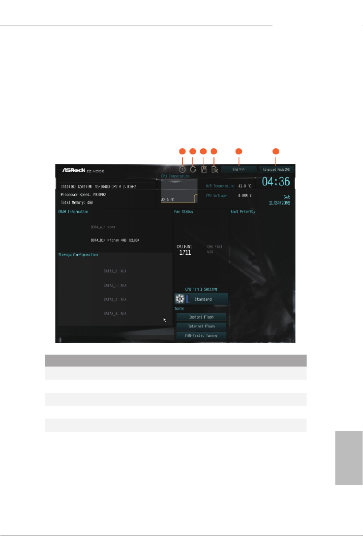
4.2 EZ Mode
e EZ Mode screen appears when you enter the BIOS setup program by default.
EZ mode is a dashboard which contains multiple readings of the system’s current
status. You can check the most crucial information of your system, such as CPU
speed, DRAM frequency, SATA information, fan speed, etc.
Press <F6> or click the "Advanced Mode" button at the upper right corner of the
screen to switch to "Advanced Mode" for more options.
1 2 3 4 5 6
No. Function
1Help
2Load UEFI Defaults
3Save Changes and Exit
4Discard Changes
5Change Language
6Switch to Advanced Mode

English
35
H470M-HVS R2.0
4.3.2 Navigation Keys
Use < > key or < > key to choose among the selections on the menu bar, and
use < > key or < > key to move the cursor up or down to select items, then
press <Enter> to get into the sub screen. You can also use the mouse to click your
required item.
Please check the following table for the descriptions of each navigation key.
Navigation Key(s) Description
+ / - To change option for the selected items
<Tab> Switch to next function
<PGUP> Go to the previous page
<PGDN> Go to the next page
<HOME> Go to the top of the screen
<END> Go to the bottom of the screen
<F1> To display the General Help Screen
<F5> Add / Remove Favorite
<F7> Discard changes and exit the SETUP UTILITY
<F9> Load optimal default values for all the settings
<F10> Save changes and exit the SETUP UTILITY
<F12> Print screen
<ESC> Jump to the Exit Screen or exit the current screen

English
38
Boot Performance Mode
Select the performance state that the BIOS will set before OS hando.
FCLK Frequency
Congure the FCLK Frequency.
Ring to Core Ratio Oset
Disable Ring to Core Ratio Oset so the ring and core can run at the same fre-
quency.
Intel SpeedStep Technology
Intel SpeedStep technology allows processors to switch between multiple frequen-
cies and voltage points for better power saving and heat dissipation.
Intel Turbo Boost Technology
Intel Turbo Boost Technology enables the processor to run above its base operating
frequency when the operating system requests the highest performance state.
Intel Speed Shift Technology
Enable/Disable Intel Speed Shi Technology support. Enabling will expose the
CPPC v2 interface to allow for hardware controlled P-states.
Intel Thermal Velocity Boost Voltage Optimizations
is service controls thermal based voltage optimizations for processors that
implment the Intel ermal Velocity Boost (TVB) feature.
DRAM Conguration
Memory Information
Allows users to browse the serial presence detect (SPD) and Intel extreme memory prole
(XMP) for DDR4 modules.
DRAM Timing Conguration
Load XMP Setting
Load XMP settings to overclock the memory and perform beyond standard specications.
DRAM Frequency
If [Auto] is selected, the motherboard will detect the memory module(s) inserted
and assign the appropriate frequency automatically.

English
39
H470M-HVS R2.0
Primary Timing
CAS# Latency (tCL)
e time between sending a column address to the memory and the beginning of the data
in response.
RAS# to CAS# Delay and Row Precharge (tRCDtRP)
RAS# to CAS# Delay : e number of clock cycles required between the opening of a row
of memory and accessing columns within it.
Row Precharge: e number of clock cycles required between the issuing of the precharge
command and opening the next row.
RAS# Active Time (tRAS)
e number of clock cycles required between a bank active command and issuing the
precharge command.
Command Rate (CR)
e delay between when a memory chip is selected and when the rst active command can
be issued.
Secondary Timing
Write Recovery Time (tWR)
e amount of delay that must elapse aer the completion of a valid write
operation, before an active bank can be precharged.
Refresh Cycle Time (tRFC)
e number of clocks from a Refresh command until the rst Activate command to
the same rank.
RAS to RAS Delay (tRRD_L)
e number of clocks between two rows activated in dierent banks of the same
rank.
RAS to RAS Delay (tRRD_S)
e number of clocks between two rows activated in dierent banks of the same
rank.
Write to Read Delay (tWTR_L)
e number of clocks between the last valid write operation and the next read command
to the same internal bank.

English
40
Write to Read Delay (tWTR_S)
e number of clocks between the last valid write operation and the next read command
to the same internal bank.
Read to Precharge (tRTP)
e number of clocks that are inserted between a read command to a row pre-
charge command to the same rank.
Four Activate Window (tFAW)
e time window in which four activates are allowed the same rank.
CAS Write Latency (tCWL)
Congure CAS Write Latency.
Third Timing
tREFI
Congure refresh cycles at an average periodic interval.
tCKE
Congure the period of time the DDR4 initiates a minimum of one refresh
command internally once it enters Self-Refresh mode.
Turn Around Timing
tRDRD_sg
Congure between module read to read delay.
tRDRD_dg
Congure between module read to read delay.
tRDRD_dr
Congure between module read to read delay.
tRDRD_dd
Congure between module read to read delay.
tRDWR_sg
Congure between module read to write delay.
tRDWR_dg
Congure between module read to write delay.

English
41
H470M-HVS R2.0
tRDWR_dr
Congure between module read to write delay.
tRDWR_dd
Congure between module read to write delay.
tWRRD_sg
Congure between module write to read delay.
tWRRD_dg
Congure between module write to read delay.
tWRRD_dr
Congure between module write to read delay.
tWRRD_dd
Congure between module write to read delay.
tWRWR_sg
Congure between module write to write delay.
tWRWR_dg
Congure between module write to write delay.
tWRWR_dr
Congure between module write to write delay.
tWRWR_dd
Congure between module write to write delay.
Round Trip Timing
Round Trip Timing Optimization
Auto is enabled in general case.
RTL Init Value
Congure round trip latency init value for round trip latency training.
IO-L Init Value
Congure IO latency init value for IO latency training.

English
42
RTL (CH A)
Congure round trip latency for channel A.
RTL (CH B)
Congure round trip latency for channel B.
IO-L (CH A)
Congure IO latency for channel A.
IO-L (CH B)
Congure IO latency for channel B.
IO-L Oset (CH A)
Congure IO latency oset for channel A.
IO-L Oset (CH B)
Congure IO latency oset for channel B.
RFR Delay (CH A)
Congure RFR Delay for Channel A.
RFR Delay (CH B)
Congure RFR Delay for Channel B.
ODT Setting
ODT WR (A1)
Congure the memory on die termination resistors' WR for channel A1.
ODT WR (B1)
Congure the memory on die termination resistors' WR for channel B1.
ODT NOM (A1)
Use this to change ODT (CH A1) Auto/Manual settings. e default is [Auto].
ODT NOM (B1)
Use this to change ODT (CH B1) Auto/Manual settings. e default is [Auto].
ODT PARK (A1)
Congure the memory on die termination resistors' PARK for channel A1.

English
43
H470M-HVS R2.0
ODT PARK (B1)
Congure the memory on die termination resistors' PARK for channel B1.
Advanced Setting
ASRock Timing Optimization
Congure the fast path through the MRC.
Realtime Memory Timing
Congure the realtime memory timings.
[Enabled] e system will allow performing realtime memory timing changes aer
MRC_DONE.
Command Tristate
Congure the Command Tristate Support.
Exit On Failure
Congure the Exit On Failure for MRC training steps.
Reset On Training Fail
Reset system if the MRC training fails.
MRC Fast Boot
Enable Memory Fast Boot to skip DRAM memory training for booting faster.
Voltage Conguration
CPU Core/Cache Voltage
Input voltage for the processor by the external voltage refulator.
GT Voltage
Congure the voltage for the integrated GPU.
VCCST Voltage
Congure the voltage for the VCCST.
PCH +1.0 Voltage
Congure the chipset voltage.
DRAM Voltage
Use this to congure DRAM Voltage. e default value is [Auto].

English
44
Save User Default
Type a prole name and press enter to save your settings as user default.
Load User Default
Load previously saved user defaults.
Save User UEFI Setup Prole to Disk
It helps you to save current UEFI settings as an user prole to disk.
Load User UEFI Setup Prole from Disk
You can load previous saved prole from the disk.

English
45
H470M-HVS R2.0
4.6 Advanced Screen
In this section, you may set the congurations for the following items: CPU
Conguration, Chipset Conguration, Storage Conguration, Super IO Congu-
ration, ACPI Conguration, USB Conguration and Trusted Computing.
UEFI Conguration
UEFI Setup Style
Select the default mode when entering the UEFI setup utility.
Active Page on Entry
Select the default page when entering the UEFI setup utility.
Full HD UEFI
When [Auto] is selected, the resolution will be set to 1920 x 1080 if the monitor
supports Full HD resolution. If the monitor does not support Full HD resolution,
then the resolution will be set to 1024 x 768. When [Disable] is selected, the
resolution will be set to 1024 x 768 directly.
Setting wrong values in this section may cause the system to malfunction.

English
46
4.6.1 CPU Conguration
Intel Hyper Threading Technology
Intel Hyper reading Technology allows multiple threads to run on each core, so
that the overall performance on threaded soware is improved.
Active Processor Cores
Select the number of cores to enable in each processor package.
CPU C States Support
Enable CPU C States Support for power saving. It is recommended to keep C3, C6
and C7 all enabled for better power saving.
Enhanced Halt State (C1E)
Enable Enhanced Halt State (C1E) for lower power consumption.
CPU C3 State Support
Enable C3 deep sleep state for lower power consumption.
CPU C6 State Support
Enable C6 deep sleep state for lower power consumption.
CPU C7 State Support
Enable C7 deep sleep state for lower power consumption.

English
47
H470M-HVS R2.0
Package C State Support
Enable CPU, PCIe, Memory, Graphics C State Support for power saving.
CFG Lock
is item allows you to disable or enable the CFG Lock.
C6DRAM
Enable/Disable moving of DRAM contents to PRM memory when CPU is in C6
state.
Intel Virtualization Technology
Intel Virtualization Technology allows a platform to run multiple operating
systems and applications in independent partitions, so that one computer system
can function as multiple virtual systems.
Hardware Prefetcher
Automatically prefetch data and code for the processor. Enable for better
performance.
Adjacent Cache Line Prefetch
Automatically prefetch the subsequent cache line while retrieving the currently
requested cache line. Enable for better performance.
Software Guard Extensions (SGX)
Intel SGX is a set of new CPU instructions that can be used by applications to set
aside private regions of code and data.

English
48
4.6.2 Chipset Conguration
Primary Graphics Adapter
Select a primary VGA.
Above 4G Decoding
Enable or disable 64bit capable Devices to be decoded in Above 4G Address Space
(only if the system supports 64 bit PCI decoding).
VT-d
Intel® Virtualization Technology for Directed I/O helps your virtual machine
monitor better utilize hardware by improving application compatibility and
reliability, and providing additional levels of manageability, security, isolation, and
I/O performance.
SR-IOV Support
If system has SR-IOV capable PCIe Devices, this option Enables or Disables Single
Root IO Virtualization Support.
DMI Link Speed
Congure DMI Slot Link Speed. Auto mode is optimizing for overclocking.
PCIE1 Link Speed
Select the link speed for PCIE1.

English
49
H470M-HVS R2.0
PCIE2 Link Speed
Select the link speed for PCIE2.
PCI Express Native Control
Select Enable for enhanced PCI Express power saving in OS.
PCIE ASPM Support
is option enables/disables the ASPM support for all CPU downstream devices.
PCH PCIE ASPM Support
is option enables/disables the ASPM support for all PCH PCIE devices.
DMI ASPM Support
is option enables/disables the control of ASPM on CPU side of the DMI Link.
PCH DMI ASPM Support
is option enables/disables the ASPM support for all PCH DMI devices.
Share Memory
Congure the size of memory that is allocated to the integrated graphics processor when
the system boots up.
IGPU Multi-Monitor
Select disable to disable the integrated graphics when an external graphics card is
installed. Select enable to keep the integrated graphics enabled at all times.
Onboard LAN
Enable or disable the onboard network interface controller.
Onboard HD Audio
Enable/disable onboard HD audio. Set to Auto to enable onboard HD audio and
automatically disable it when a sound card is installed.
Front Panel
Enable/disable front panel HD audio.
Onboard HDMI HD Audio
Enable audio for the onboard digital outputs.

English
50
Deep Sleep
Congure deep sleep mode for power saving when the computer is shut down.
Restore on AC/Power Loss
Select the power state aer a power failure. If [Power O] is selected, the power will
remain o when the power recovers. If [Power On] is selected, the system will start
to boot up when the power recovers.
English
51
H470M-HVS R2.0
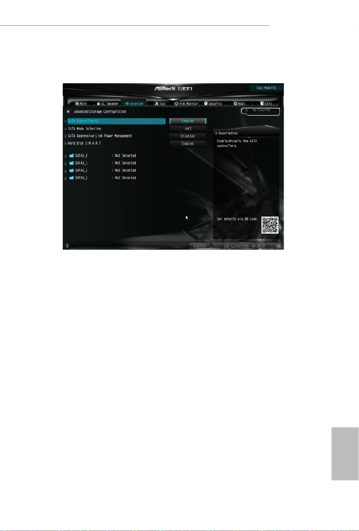
4.6.3 Storage Conguration
SATA Controller(s)
Enable/disable the SATA controllers.
SATA Mode Selection
AHCI: Supports new features that improve performance.
RAID: Combine multiple disk drives into a logical unit.
SATA Aggressive Link Power Management
SATA Aggressive Link Power Management allows SATA devices to enter a low
power state during periods of inactivity to save power. It is only supported by AHCI
mode.
Hard Disk S.M.A.R.T.
S.M.A.R.T stands for Self-Monitoring, Analysis, and Reporting Technology. It is a
monitoring system for computer hard disk drives to detect and report on various
indicators of reliability.

English
52
4.6.4 Super IO Conguration
PS2 Y-Cable
Enable the PS2 Y-Cable or set this option to Auto.

English
53
H470M-HVS R2.0
4.6.5 ACPI Conguration
Suspend to RAM
Select disable for ACPI suspend type S1. It is recommended to select auto for ACPI
S3 power saving.
PS/2 Keyboard S4/S5 Wakeup Support
Allow the system to be waked up by a PS/2 Keyboard in S4/S5.
PCIE Devices Power On
Allow the system to be waked up by a PCIE device and enable wake on LAN.
RTC Alarm Power On
Allow the system to be waked up by the real time clock alarm. Set it to By OS to let
it be handled by your operating system.
USB Keyboard/Remote Power On
Allow the system to be waked up by an USB keyboard or remote controller.
USB Mouse Power On
Allow the system to be waked up by an USB mouse.

English
55
H470M-HVS R2.0
4.6.7 Trusted Computing
Security Device Support
Enable or disable BIOS support for security device.

English
56
4.7 Tools
UEFI Tech Service
Contact ASRock Tech Service if you are having trouble with your PC. Please setup
network conguration before using UEFI Tech Service.
Easy RAID Installer
Easy RAID Installer helps you to copy the RAID driver from the support CD to
your USB storage device. Aer copying the drivers please change the SATA mode
to RAID, then you can start installing the operating system in RAID mode.
SSD Secure Erase Tool
All the SSD's listed that supports Secure Erase function.
Instant Flash
Save UEFI les in your USB storage device and run Instant Flash to update your
UEFI.
Internet Flash - DHCP (Auto IP), Auto
ASRock Internet Flash downloads and updates the latest UEFI rmware version
from our servers for you. Please setup network conguration before using Internet
Flash.
*For BIOS backup and recovery purpose, it is recommended to plug in your USB
pen drive before using this function.
Product specificaties
| Merk: | Asrock |
| Categorie: | Moederbord |
| Model: | H470M-HVS R2.0 |
Heb je hulp nodig?
Als je hulp nodig hebt met Asrock H470M-HVS R2.0 stel dan hieronder een vraag en andere gebruikers zullen je antwoorden
Handleiding Moederbord Asrock

24 Maart 2025
18 November 2024
12 November 2024
26 September 2024
24 Mei 2024
25 Maart 2024
27 Februari 2024
6 Januari 2024
6 Januari 2024
5 Januari 2024
Handleiding Moederbord
- Moederbord Asus
- Moederbord EPoX
- Moederbord Evga
- Moederbord Gigabyte
- Moederbord MSI
- Moederbord Sharkoon
- Moederbord NZXT
- Moederbord Intel
- Moederbord Supermicro
- Moederbord ECS
- Moederbord Foxconn
- Moederbord Advantech
- Moederbord Elitegroup
- Moederbord Biostar
Nieuwste handleidingen voor Moederbord

8 April 2025
8 April 2025
3 April 2025
3 April 2025
3 April 2025
3 April 2025
2 April 2025
2 April 2025

29 Maart 2025
27 Maart 2025