Asrock H170 Pro4/D3 Handleiding
Asrock
Moederbord
H170 Pro4/D3
Lees hieronder de 📖 handleiding in het Nederlandse voor Asrock H170 Pro4/D3 (78 pagina's) in de categorie Moederbord. Deze handleiding was nuttig voor 39 personen en werd door 2 gebruikers gemiddeld met 4.5 sterren beoordeeld
Pagina 1/78


Version 1.0
Published July 2015
Copyright©2015 ASRock INC. All rights reserved.
Copyright Notice:
No part of this documentation may be reproduced, transcribed, transmitted, or
translated in any language, in any form or by any means, except duplication of
documentation by the purchaser for backup purpose, without written consent of
ASRock Inc.
Products and corporate names appearing in this documentation may or may not
be registered trademarks or copyrights of their respective companies, and are used
only for identication or explanation and to the owners’ benet, without intent to
infringe.
Disclaimer:
Specications and information contained in this documentation are furnished for
informational use only and subject to change without notice, and should not be
constructed as a commitment by ASRock. ASRock assumes no responsibility for
any errors or omissions that may appear in this documentation.
With respect to the contents of this documentation, ASRock does not provide
warranty of any kind, either expressed or implied, including but not limited to
the implied warranties or conditions of merchantability or tness for a particular
purpose.
In no event shall ASRock, its directors, ocers, employees, or agents be liable for
any indirect, special, incidental, or consequential damages (including damages for
loss of prots, loss of business, loss of data, interruption of business and the like),
even if ASRock has been advised of the possibility of such damages arising from any
defect or error in the documentation or product.
is device complies with Part 15 of the FCC Rules. Operation is subject to the following
two conditions:
(1) this device may not cause harmful interference, and
(2) this device must accept any interference received, including interference that
may cause undesired operation.
CALIFORNIA, USA ONLY
e Lithium battery adopted on this motherboard contains Perchlorate, a toxic substance
controlled in Perchlorate Best Management Practices (BMP) regulations passed by the
California Legislature. When you discard the Lithium battery in California, USA, please
follow the related regulations in advance.
“Perchlorate Material-special handling may apply, see www.dtsc.ca.gov/hazardouswaste/
perchlorate”
ASRock Website: http://www.asrock.com

e terms HDMI™ and HDMI High-Denition Multimedia Interface, and the HDMI
logo are trademarks or registered trademarks of HDMI Licensing LLC in the United
States and other countries.

Contents
Chapter 1 Introduction 1
1.1 Package Contents 1
1.2 Specications 2
1.3 Motherboard Layout 6
1.4 I/O Panel 8
Chapter 2 Installation 10
2.1 Installing the CPU 11
2.2 Installing the CPU Fan and Heatsink 14
2.3 Installing Memory Modules (DIMM) 15
2.4 Expansion Slots (PCI Express Slots) 17
2.5 Jumpers Setup 18
2.6 Onboard Headers and Connectors 19
2.7 CrossFireXTM and Quad CrossFireXTM Operation Guide 24
2.7.1 Installing Two CrossFireXTM-Ready Graphics Cards 24
2.7.2 Driver Installation and Setup 26
Chapter 3 Software and Utilities Operation 27
3.1 Installing Drivers 27
3.2 A-Tuning 28
3.2.1 Installing A-Tuning 28
3.2.2 Using A-Tuning 28
3.3 ASRock Live Update & APP Shop 32
3.3.1 UI Overview 32

1
English
H170 Pro4/D3
Chapter 1 Introduction
ank you for purchasing ASRock H170 Pro4/D3 motherboard, a reliable
motherboard produced under ASRock’s consistently stringent quality control.
It delivers excellent performance with robust design conforming to ASRock’s
commitment to quality and endurance.
In this documentation, Chapter 1 and 2 contains the introduction of the
motherboard and step-by-step installation g uides. Chapter 3 contains the operation
guide of the soware and utilities. Chapter 4 contains the conguration g uide of
the BIOS setup.
1.1 Package Contents
• ASRock H170 Pro4/D3 Motherboard (ATX Form Factor)
• ASRock H170 Pro4/D3 Quick Installation Guide
• ASRock H170 Pro4/D3 Support CD
• 2 x Serial ATA (SATA) Data Cables (Optional)
• 1 x I/O Panel Shield
Because the motherboard specications and the BIOS soware might be updated , the
content of this documentation will be subject to change without notice. In case any modi-
cations of this documentation occur, the updated version will be available on ASRock’s
website without further notice. If you require technical support related to this mother-
board, please visit our website for specic information about the model you are using. You
may nd the latest VGA cards and CPU support list on ASRock’s website as well. ASRock
website http://www.asrock.com.

2
English
1.2 Specications
Platform • ATX Form Factor
• Solid Capacitor design
• High Density Glass Fabric PCB
CPU • Supports 6th Generation Intel® CoreTM i7/i5/i3/Pentium®/
Celeron® Processors (Socket 1151)
• Supports Intel® Turbo Boost 2.0 Technology
Chipset • Intel® H170
• Supports Intel® Small Business Advantage 4.0
Memory • Dual Channel DDR3/DDR3L Memory Technology
• 4 x DDR3/DDR3L DIMM Slots
• Supports DDR3/DDR3L 1600/1333/1066 non-ECC, un-
buered memory
• Supports ECC UDIMM memory modules (operate in non-
ECC mode)
• Max. capacity of system memory: 64GB
• Supports Intel® Extreme Memory Prole (XMP) 1.3 / 1.2
Expansion
Slot
• 2 x PCI Express 3.0 x16 Slots (PCIE2: x16 mode; PCIE4: p7-x4
mode)
• 3 x PCI Express 3.0 p7-x1 Slots (Flexible PCIe)
• Supports AMD Quad CrossFireXTM and CrossFireXTM
Graphics * Intel® HD Graphics Built-in Visuals and the VGA outputs can
be supported only with processors which are GPU integrated.
• - Supports Intel® HD Graphics Built-in Visuals : Intel®
Quick Sync Video with AVC, MVC (S3D) and MPEG-2 Full
HW Encode1, Intel® InTruTM 3D, Intel® Clear Video HD
Technology, Intel® Insider
TM, Intel® HD Graphics 510/530
• Pixel Shader 5.0, DirectX 12
• Max. shared memory 1792MB
• Dual graphics output: Support DVI-D and HDMI ports by
independent display controllers

3
English
H170 Pro4/D3
• Supports HDMI with max. resolution up to 4K x 2K
(4096x2304) @ 24Hz
• Supports DVI-D with max. resolution up to 1920x1200 @
60Hz
• Supports Auto Lip Sync, Deep Color (12bpc), xvYCC and
HBR (High Bit Rate Audio) with HDMI Port
(Compliant HDMI monitor is required)
• Supports Accelerated Media Codecs: HEVC, VP8, VP9
• Supports HDCP with DVI-D and HDMI Ports
• Supports Full HD 1080p Blu-ray (BD) playback with DVI-D
and HDMI Ports
Audio • 7.1 CH HD Audio with Content Protection (Realtek ALC892
Audio Codec)
* To congure 7.1 CH HD Audio, it is required to use an HD
front panel audio module and enable the multi-channel audio
feature through the audio driver.
• Premium Blu-ray Audio support
• Supports Surge Protection (ASRock Full Spike Protection)
• ELNA Audio Caps
LAN • PCIE p8-x1 Gigabit LAN 10/100/1000 Mb/s
• Realtek RTL8111GR
• Supports Wake-On-WAN
• Supports Wake-On-LAN
• Supports Lightning/ESD Protection (ASRock Full Spike
Protection)
• Supports LAN Cable Detection
• Supports Energy Ecient Ethernet 802.3az
• Supports PXE
Rear Panel
I/O
• 1 x PS/2 Mouse Port
• 1 x PS/2 Keyboard Port
• 1 x DVI-D Port
• 1 x HDMI Port

4
English
• 6 x USB 3.0 Ports (Supports ESD Protection (ASRock Full
Spike Protection))
• 1 x RJ-45 LAN Port with LED (ACT/LINK LED and SPEED
LED)
• HD Audio Jacks: Line in / Front Speaker / Microphone
Storage • 6 x SATA3 6.0 Gb/s Connectors, support RAID (RAID 0,
RAID 1, RAID 5, RAID 10, Intel Rapid Storage Technology
14 and Intel Smart Response Technology), NCQ, AHCI and
Hot Plug
• 2 x SATA Express 10 Gb/s Connectors*
* Support to be announced
Connector • 1 x COM Port Header
• 1 x TPM Header
• 1 x Power LED and Speaker Header
• 1 x CPU Fan Connector (4-pin)
• 2 x Chassis Fan Connectors (1 x 4-pin, 1 x 3-pin)
* e CPU Fan Connector supports the CPU fan of maxi-
mum 1A (12W) fan power.
• 1 x 24 pin ATX Power Connector
• 1 x 8 pin 12V Power Connector
• 1 x Front Panel Audio Connector
• 2 x USB 2.0 Headers (Support 4 USB 2.0 ports) (Supports
ESD Protection (ASRock Full Spike Protection))
• 1 x USB 3.0 Header (Supports 2 USB 3.0 ports) (Supports
ESD Protection (ASRock Full Spike Protection))
BIOS
Feature
• 128Mb AMI UEFI Legal BIOS with multilingual GUI sup-
port
• ACPI 1.1 Compliant wake up events
• SMBIOS 2.3.1 Support
• CPU, GT_CPU, DRAM, VPPM, PCH 1.0V, VCCIO, VCCSA
Voltage Multi-adjustment
6
English
Intel
H170
DDR3_A2 (6 4 bit, 2 40-p in mod ul e)
DDR3_A1 (6 4 bit, 2 40-p in mod ul e)
DDR3_B2 (6 4 bit, 2 40-p in mod ul e)
DDR3_B1 (6 4 bit, 2 40-p in mod ul e)
ATX 112 V
CMOS
Battery
Su pe r
I/ O
ATXPWR1
1
USB 3_4_ 5
LA N
Top:
RJ -45
US 3.B 0
T: 4USB
B: USB 5
CL RCM OS 1
1
HDLED ESET R
PLED PW RBT N
PANEL1
1
USB2 _3
1
CO M1
1
1
HD_ AUDIO 1
H170 3Pro4/D
SATA3 _1_3 SATA3 _0_2
PCIE5
RoHS
7
8
9
10
1719
11
12
1520
18
2
CPU _FA N1
3 4
6
51
128Mb
BIOS
US 3 .B 0
T: USB0
B: U SB1
Aud i o
CO DE C
PCIE2
PC ExpressI 03.
Front B 0US 3.
CHA_FAN2
HDM I1
DVI1
US 3 .B 0
T: USB2
B: U SB3
CHA_FAN1
SA 3_ 5T A
USB4 _5
1
TPM S1
1
SA A3 _4T
1416
Top:
LI NE IN
Ce nt er :
FR ONT
Bo t t om :
MI C IN
PS2
Ke yb oa rd
PS2
Mo us e
PCIE1
PCIE4
PCIE3
1
SP K_PLE D1
21
SATA_ E_12
13
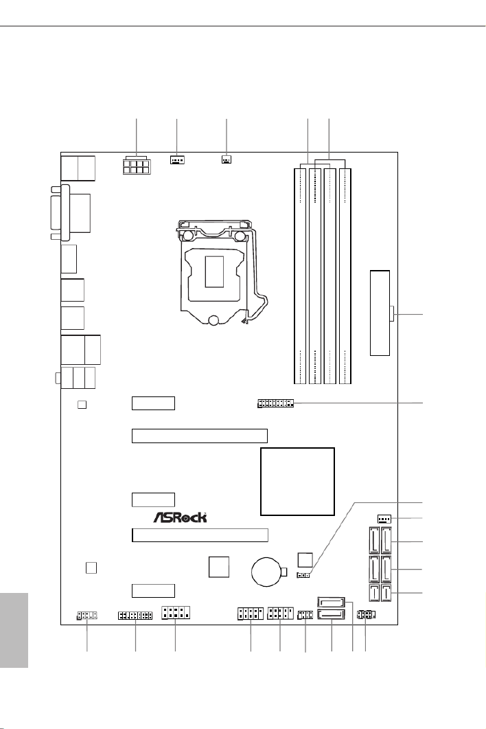
1.3 Motherboard Layout

7
English
H170 Pro4/D3
No. Description
1 ATX 12V Power Connector (ATX12V1)
2 CPU Fan Connector (CPU_FAN1)
3 Chassis Fan Connector (CHA_FAN2)
4 2 x 240-pin DDR3/DDR3L DIMM Slots (DDR3_A1, DDR3_B1)
5 2 x 240-pin DDR3/DDR3L DIMM Slots (DDR3_A2, DDR3_B2)
6 ATX Power Connector (ATXPWR1)
7 USB 3.0 Header (USB3_4_5)
8 Clear CMOS Jumper (CLRMOS1)
9 Chassis Fan Connector (CHA_FAN1)
10 SATA3 Connectors (SATA3_0_2)
11 SATA3 Connectors (SATA3_1_3)
12 SATA Express Connectors (SATA_E_12)
13 System Panel Header (PANEL1)
14 SATA3 Connector (SATA3_4)
15 SATA3 Connector (SATA3_5)
16 Power LED and Speaker Header (SPK_PLED1)
17 USB 2.0 Header (USB2_3)
18 USB 2.0 Header (USB4_5)
19 COM Port Header (COM1)
20 TPM Header (TPMS1)
21 Front Panel Audio Header (HD_AUDIO1)

8
English
1.4 I/O Panel
No. No.Description Description
1 PS/2 Mouse Port (Green) 7 USB 3.0 Ports (USB3_23)
2 LAN RJ-45 Port* 8 USB 3.0 Ports (USB3_01)
3 Line In (Light Blue)** 9 HDMI Port
4 Front Speaker (Lime)** 10 DVI-D Port
5 Microphone (Pink)** PS/2 Keyboard Port (Purple)11
6 USB 3.0 Ports (USB3_45)
5
6
79
2
4
3
1011
1
8
* ere are two LEDs on each LAN port. Please refer to the table below for the LAN port LED indications.
Activity / Link LED Speed LED
Status StatusDescription Description
O ONo Link 10Mbps connection
Blinking Data Activity Orange 100Mbps connection
On Link Green 1Gbps connection
ACT/LINK LED
SPEED LED
LAN Port

9
English
H170 Pro4/D3
** To congure 7.1 CH HD Audio, it is required to use an HD front panel audio module and enable the multi-
channel audio feature through the audio driver.
Please set Speaker Conguration to “7.1 Speaker”in the Realtek HD Audio Manager.
Function of the Audio Ports in 7.1-channel Conguration:
Port Function
Light Blue (Rear panel) Rear Speaker Out
Lime (Rear panel) Front Speaker Out
Pink (Rear panel) Central /Subwoofer Speaker Out
Lime (Front panel) Side Speaker Out

10
English
is is an ATX form factor motherboard. Before you install the motherboard, study
the conguration of your chassis to ensure that the motherboard ts into it.
Pre-installation Precautions
Take note of the following precautions before you install motherboard components
or change any motherboard settings.
• Make sure to unplug the power cord before installing or removing the motherboard
components. Failure to do so may cause physical injuries and damages to motherboard
components.
• In order to avoid damage from static electricity to the motherboard’s components,
NEVER place your motherboard directly on a carpet. Also remember to use a grounded
wrist strap or touch a safety grounded object before you handle the components.
• Hold components by the edges and do not touch the ICs.
• Whenever you uninstall any components, place them on a grounded anti-static pad or
in the bag that comes with the components.
• When placing screws to secure the motherboard to the chassis, please do not over-
tighten the screws! Doing so may damage the motherboard.
Chapter 2 Installation

11
English
H170 Pro4/D3
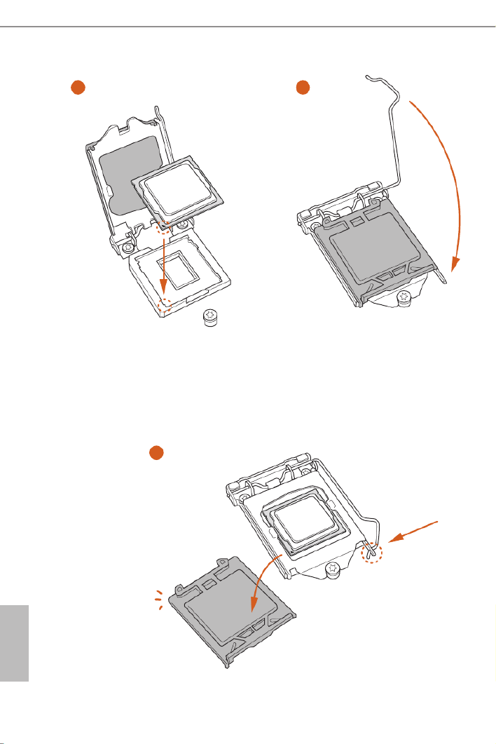
2.1 Installing the CPU
1. Before you insert the 1151-Pin CPU into the socket, please check if the is on the PnP cap
socket, if the CPU surface is unclean, or if there are any bent pins in the socket. Do not
force to insert the CPU into the socket if above situation is found. Otherwise, the CPU
will be seriously damaged.
2. Unplug all power cables before installing the CPU.
1
2
A
B
12
English
4
5
3

13
English
H170 Pro4/D3
Please save and replace the cover if the processor is removed. e cover must be placed if
you wish to return the motherboard for aer service.
14
English
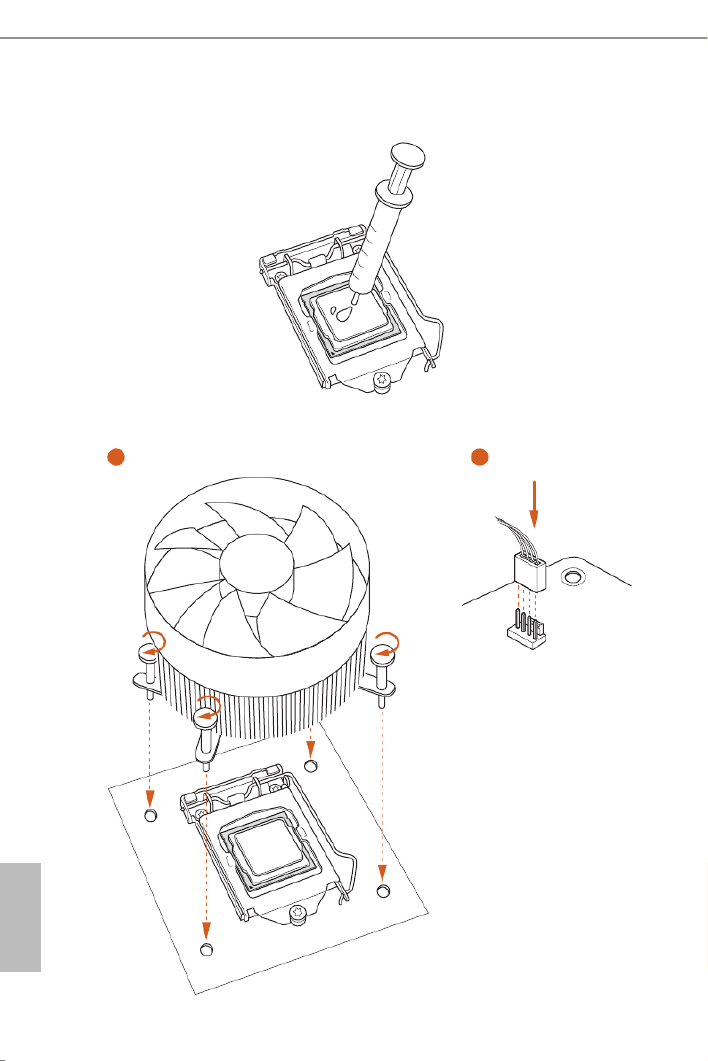
2.2 Installing the CPU Fan and Heatsink
1 2
CPU_ FAN

15
English
H170 Pro4/D3
2.3 Installing Memory Modules (DIMM)
is motherboard provides four 240-pin DDR3/DDR3L (Double Data Rate 3)
DIMM slots, and supports Dual Channel Memory Technology.
Dual Channel Memory Conguration
e DIMM only ts in one correct orientation. It will cause permanent damage to the
motherboard and the DIMM if you force the DIMM into the slot at incorrect orientation.
1. For dual channel conguration, you always need to install identical (the same brand,
speed, size and chip-type) DDR3/DDR3L DIMM pairs.
2. It is unable to activate Dual Channel Memory Technology with only one memory module
installed.
3. It is not allowed to install a DDR or DDR2 memory module into a DDR3/DDR3L slot;
otherwise, this motherboard and DIMM may be damaged..
Priority DDR3_A1 DDR3_A2 DDR3_B1 DDR3_B2
1Populated Populated
2Populated Populated
3Populated Populated Populated Populated

16
English
1
2
3

17
English
H170 Pro4/D3
2.4 Expansion Slots (PCI Express Slots)
ere are 5 PCI Express slots on the motherboard.
PCIe slots:
PCIE1 (PCIe 3.0 p22-x1 slot) is used for PCI Express p22-x1 lane width cards.
PCIE2 (PCIe 3.0 x16 slot) is used for PCI Express x16 lane width graphics cards.
PCIE3 (PCIe 3.0 p22-x1 slot) is used for PCI Express p22-x1 lane width cards.
PCIE4 (PCIe 3.0 x16 slot) is used for PCI Express p22-x4 lane width graphics cards.
PCIE5 (PCIe 3.0 p22-x1 slot) is used for PCI Express p22-x1 lane width cards.
Before installing an expansion card, please make sure that the power supply is switched o
or the power cord is unplugged. Please read the documentation of the expansion card and
make necessary hardware settings for the card before you start the installation.
18
English
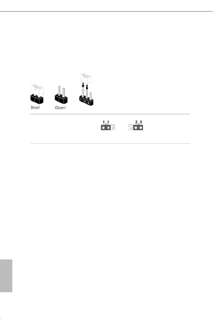
2.5 Jumpers Setup
e illustration shows how jumpers are setup. When the jumper cap is placed on
the pins, the jumper is “Short”. If no jumper cap is placed on the pins, the jumper
is “Open”. e illustration shows a 3-pin jumper whose pin1 and pin2 are “Short”
when a jumper cap is placed on these 2 pins.
Clear CMOS Jumper
(CLRMOS1)
(see p.6, No. 8)
CLRMOS1 allows you to clear the data in CMOS. To clear and reset the system
parameters to default setup, please turn o the computer and unplug the power
cord from the power supply. Aer waiting for 15 seconds, use a jumper cap to
short pin2 and pin3 on CLRMOS1 for 5 seconds. However, please do not clear the
CMOS right aer you update the BIOS. If you need to clear the CMOS when you
just nish updating the BIOS, you must boot up the system rst, and then shut it
down before you do the clear-CMOS action. Please be noted that the password,
date, time, and user default prole will be cleared only if the CMOS battery is
removed.
Clear CMOSDefault
19
English
H170 Pro4/D3
2.6 Onboard Headers and Connectors
System Panel Header
(9-pin PANEL1)
(see p.6, No. 13)
Connect the power
switch, reset switch and
system status indicator on
the chassis to this header
according to the pin
assignments below. Note
the positive and negative
pins before connecting
the cables.
GN D
R #ESE T
PW RBT N#
PL E D-
PL E D+
GN D
HDL E D-
HDL E D+
1
GN D
PWRBTN (Power Switc h):
Connect to the power s witch on the chassis f ront panel. You may cong ure the way to turn
o your system using the power switch.
RESET (Reset Switch):
Connect to the reset switch on the chassis front panel. Press the reset switch to restart the
computer if the computer freezes and fails to perform a normal restart.
PLED (System Power LED):
Connect to the power status indicator on the chassis front panel. e LED is on when the
system is operating. e LED keeps blinking when the system is in S1/S3 sleep state. e
LED is o when the system is in S4 sleep state or powered o (S5).
HDLED (Hard Drive Activity LED):
Connect to the hard drive activity LED on the chassis front panel. e LED is on when the
hard drive is reading or writing data.
e front panel design may dier by chassis. A front panel module mainly consists of power
switch, reset switch, power LED, hard drive activity LED, speaker and etc. When connect-
ing your chassis front panel module to this header, make sure the wire assignments and the
pin assignments are matched correctly.
Onboard headers and connectors are NOT jumpers. Do NOT place jumper caps over these
headers and connectors. Placing jumper caps over the headers and connectors will cause
permanent damage to the motherboard.

20
English
Power LED and Speaker
Header
(7-pin SPK_PLED1)
(see p.6, No. 16)
Please connect the
chassis power LED and
the chassis speaker to this
header.
Serial ATA3 Connectors
(SATA3_0_2)
(see p.6, No. 10)
(SATA3_1_3)
(see p.6, No. 11)
(SATA3_4)
(see p.6, No. 14)
(SATA3_5)
(see p.6, No. 15)
ese six SATA3
connectors support SATA
data cables for internal
storage devices with up to
6.0 Gb/s data transfer rate.
Serial ATA Express
Connectors
(SATA_E_12:
see p.7, No. 12)
Please connect either
SATA or PCIe storage
devices to these
connectors.
USB 2.0 Headers
(9-pin USB2_3)
(see p.6, No. 17)
(9-pin USB4_5)
(see p.6, No. 18)
DUMMY
GND
GND
+B
-B
U RSB_PW
+A
-A
U RSB_PW
1
ere are two headers
on this motherboard.
Each USB 2.0 header can
support two ports.
1
+5V
DUMMY
PLED+
PLED+
PLED-
DUMMY
SPEAKER
SATA3_0
SATA3_2
SATA3_1
SATA3_3
SATA3_4
SATA3_5
SATA3_0
SATA3_2
SATA3_1
SATA3_3
SATA_E_1
SATA_E_2
21
English
H170 Pro4/D3
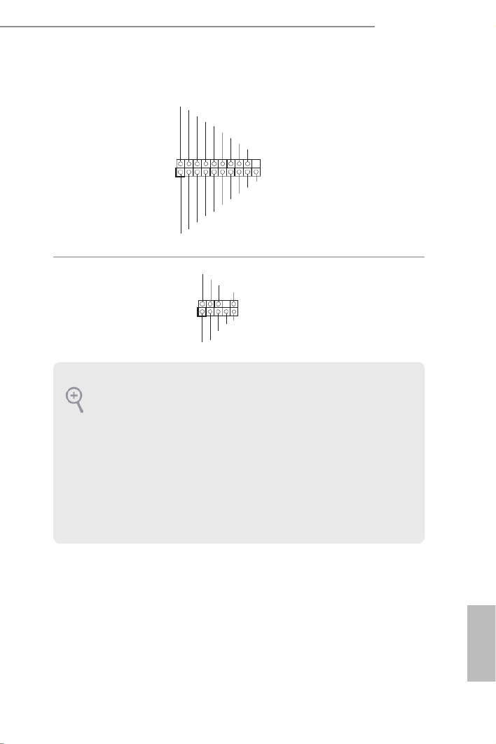
USB 3.0 Header
(19-pin USB3_4_5)
(see p.6, No. 7)
1
Dumm y
GND
GND
Vbus
GND
GND
IntA _PA_SSR X+
Vbus
IntA _PA_D+
IntA _PA_D-
IntA _PA_SST X+
IntA _PA_SST X-
IntA _PA_SSR X-
IntA _PB_SSR X-
IntA _PB_SSR X+
IntA _PB_SST X-
IntA _PBA_SS TX+
IntA _PB_D-
IntA _PB_D+
Besides four USB 3.0
ports on the I/O panel,
there is one header on this
motherboard. Each USB
3.0 header can support
two ports.
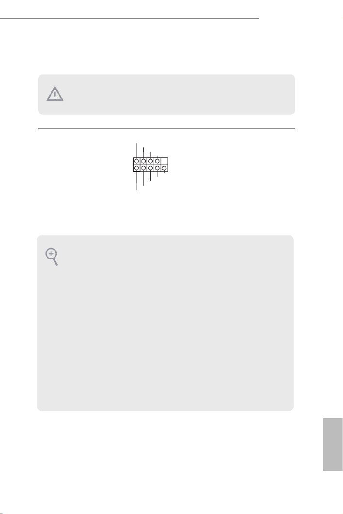
Front Panel Audio Header
(9-pin HD_AUDIO1)
(see p.6, No. 21)
J_SENSE
OUT2_L
1
MIC_RET
PRESENC E#
GND
OUT2_R
MIC2_R
MIC2_L
OUT_RET
is header is for
connecting audio devices
to the front audio panel.
1. High Denition Audio supports Jack Sensing, but the panel wire on the chassis must sup-
port HDA to function correctly. Please follow the instructions in our manual and chassis
manual to install your system.
2. If you use an AC’97 audio panel, please install it to the front panel audio header by the
steps below:
A. Connect Mic_IN (MIC) to MIC2_L.
B. Connect Audio_R (RIN) to OUT2_R and Audio_L (LIN) to OUT2_L.
C. Connect Ground (GND) to Ground (GND).
D. MIC_RET and OUT_RET are for the HD audio panel only. You don’t need to connect
them for the AC’97 audio panel.
E. To activate the front mic, go to the “FrontMic” Tab in the Realtek Control panel and
adjust “Recording Volume”.

22
English
Chassis Fan Connectors
(4-pin CHA_FAN1)
(see p.6, No. 9)
(3-pin CHA_FAN2)
(see p.6, No. 3)
GND
FAN_VOLTAGE
CHA_FAN_SPEED
F LAN_SPEED_CONTRO
GND
FAN_VOLTAGE
CHA_FAN_SPEED
Please connect fan cables
to the fan connector and
match the black wire to
the ground pin.
CPU Fan Connector
(4-pin CPU_FAN1)
(see p.6, No. 2)
GND
FAN_VOLTAGE
CPU_FAN_SPEED
FAN_SPEED_CONTROL
1 2 3 4
is motherboard pro-
vides a 4-Pin CPU fan
(Quiet Fan) connector.
If you plan to connect a
3-Pin CPU fan, please
connect it to Pin 1-3.
ATX Power Connector
(24-pin ATXPWR1)
(see p.6, No. 6)
is motherboard pro-
vides a 24-pin ATX power
connector. To use a 20-pin
ATX power supply, please
plug it along Pin 1 and Pin
13.
ATX 12V Power
Connector
(8-pin ATX12V1)
(see p.6, No. 1)
4 1
8 5 is motherboard pro-
vides a 8-pin ATX 12V
power connector.
Serial Port Header
(9-pin COM1)
(see p.6, No. 19)
e COM1 header
supports a serial port
module.
CCTS#1
RRTS#1
DDSR#1
DDTR#1
RRXD1
GND
TTXD1
DDCD#1
1
RRI#1
1
12
13
24

23
English
H170 Pro4/D3
TPM Header
(17-pin TPMS1)
(see p.6, No. 20)
is connector supports Trusted
Platform Module (TPM) system,
which can securely store keys,
digital certicates, passwords,
and data. A TPM system also
helps enhance network security,
protects digital identities, and
ensures platform integrity.
1
GN D
SMB_DAT A_MAIN
LAD2
LAD1
GN D
S_PWRDW N #
SERIRQ #
GN
D
P CIC L K
P CIR ST #
LAD3
+3 V
LAD0
+3VS B
GN D
FRAM E
SMB_CLK _MAIN
24
English
2.7 CrossFireXTM and Quad CrossFireXTM Operation Guide
is motherboard supports CrossFireXTM and Quad CrossFireXTM that allows you
to install up to three identical PCI Express p29-x16 graphics cards.
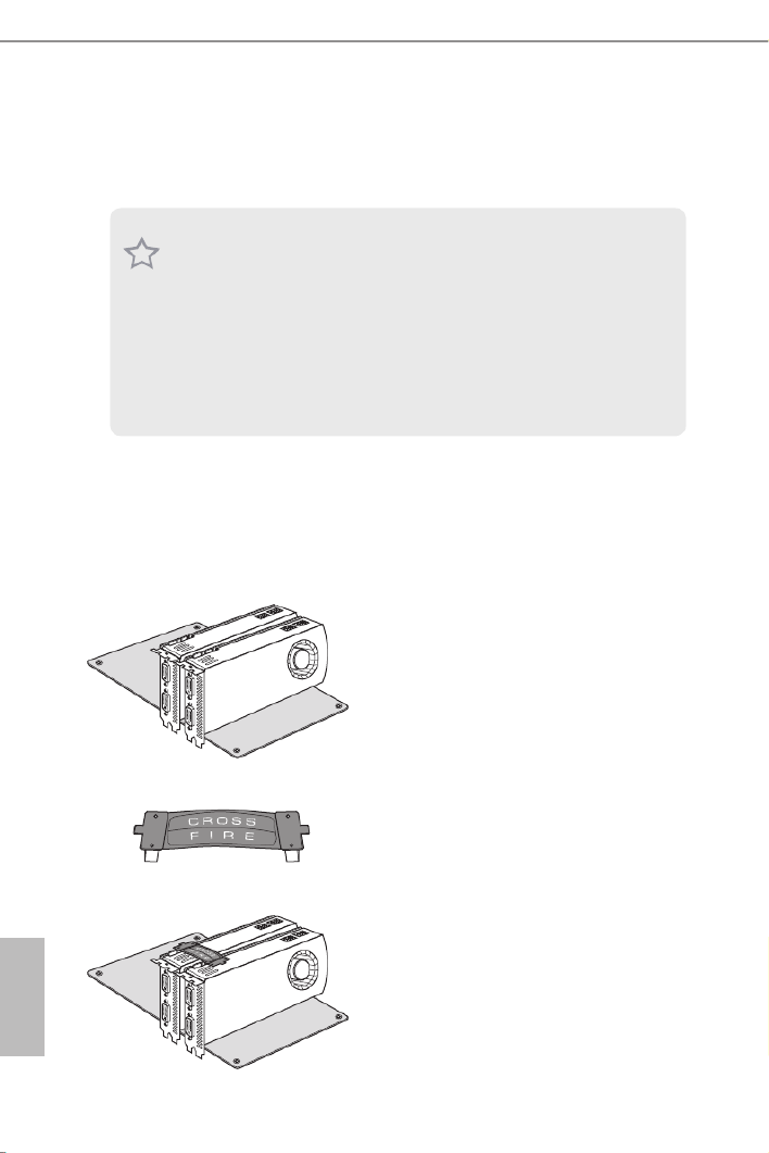
2.7.1 Installing Two CrossFireXTM-Ready Graphics Cards
Step 1
Insert one graphics card into PCIE2 slot
and the other graphics card to PCIE4 slot.
Make sure that the cards are properly
seated on the slots.
Step 2
Connect two graphics cards by installing
a CrossFire Bridge on the CrossFire Bridge
Interconnects on the top of the graphics
cards. (e CrossFire Bridge is provided
with the graphics card you purchase, not
bundled with this motherboard. Please
refer to your graphics card vendor for
details.)
1. You should only use identical CrossFireX
TM-ready graphics cards that are AMD certied.
2. Make sure that your graphics card driver supports AMD CrossFireX
TM technology.
Download the drivers from the AMD’s website: www.amd.com
3. Make sure that your power supply unit (PSU) can provide at least the minimum power
your system requires. It is recommended to use a AMD certied PSU. Please refer to the
AMD’s website for details.
4. If you pair a 12-pipe CrossFireXTM
Edition card with a 16-pipe card, both cards will oper-
ate as 12-pipe cards while in CrossFireX
TM mode.
5. Dierent CrossFireXTM cards may require dierent methods to enable CrossFireX
TM.
Please refer to AMD graphics card manuals for detailed installation guide.
CrossFire Bridge
25
English
H170 Pro4/D3
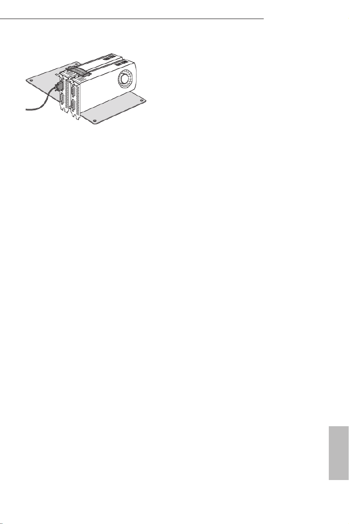
Step 3
Connect a VGA cable or a DVI cable to the
monitor connector or the DVI connec-
tor of the graphics card that is inserted to
PCIE2 slot.

26
English
Step 1
Power on your computer and boot into OS.
Step 2
Remove the AMD drivers if you have any VGA drivers installed in your system.
Step 3
Install the required drivers and CATALYST Control Center then restart your
computer. Please check AMD’s website for details.
2.7.2 Driver Installation and Setup
Step 4
Double-click the AMD Catalyst Control
Center icon in the Windows
® system tray.
Step 5
In the le pane, click and Performance
then AMD CrossFireXTM . en select
Enable AMD CrossFireX and click Apply.
Select the GPU number according to your
graphics card and click .Apply
AMD Catalyst Control Center
e Catalyst Uninstaller is an optional download. We recommend using this utility to un-
install any previously installed Catalyst drivers prior to installation. Please check AMD’s
website for AMD driver updates.

27
English
H170 Pro4/D3
Chapter 3 Software and Utilities Operation
3.1 Installing Drivers
e Support CD that comes with the motherboard contains necessary drivers and
useful utilities that enhance the motherboard’s features.
Running The Support CD
To begin using the support CD, insert the CD into your CD-ROM drive. e CD
automatically displays the Main Menu if “AUTORUN” is enabled in your computer.
If the Main Menu does not appear automatically, locate and double click on the le
“ASRSETUP.EXE” in the Support CD to display the menu.
Drivers Menu
e drivers compatible to your system will be auto-detected and listed on the
support CD driver page. Please click Install All or follow the order from top to
bottom to install those required drivers. erefore, the drivers you install can work
properly.
Utilities Menu
e Utilities Menu shows the application soware that the motherboard supports.
Click on a specic item then follow the installation wizard to install it.
To improve Windows 7 compatibility, please download and install the following hot x
provided by Microso.
“KB2720599”: http://support.microso.com/kb/2720599/en-us

28
English
3.2 A-Tuning
A-Tuning is ASRock’s multi purpose soware suite with a new interface, more new
features and improved utilities.
3.2.1 Installing A-Tuning
Formula Drive (A-Tuning/F-Stream) can be downloaded from ASRock Live Update
& APP Shop. Aer the installation, you will nd the icon “A-Tuning“ on your
desktop. Double-click the “A-Tuning A-Tuning“ icon, main menu will pop up.
3.2.2 Using A-Tuning
ere are six sections in A-Tuning main menu: Operation Mode, OC Tweaker,
System Info, FAN-Tastic Tuning, Tech Service and Settings.
Operation Mode
Choose an operation mode for your computer.

29
English
H170 Pro4/D3
OC Tweaker
Congurations for overclocking the system.
System Info
View information about the system.
*e System Browser tab may not appear for certain models.
30
English
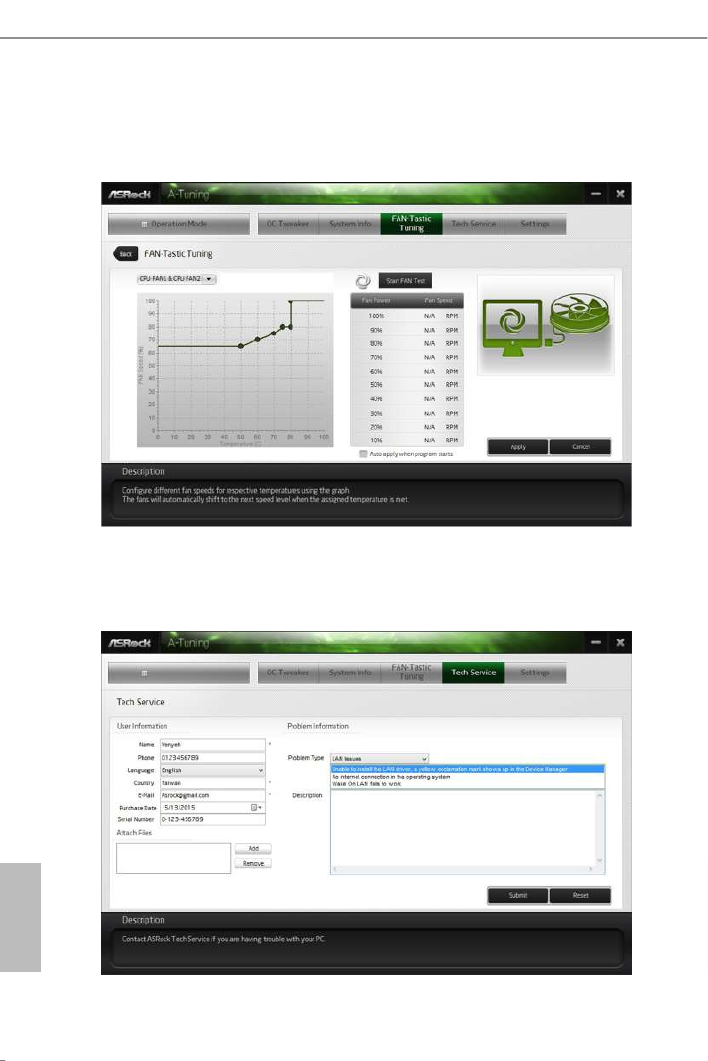
FAN-Tastic Tuning
Congure up to ve dierent fan speeds using the graph. e fans will automatically shi
to the next speed level when the assigned temperature is met.
Tech Service
Contact Tech Service if you have problems with your computer. Please leave your
contact information along with details of the problem.

31
English
H170 Pro4/D3
Settings
Congure ASRock A-Tuning. Click to select "Auto run at Windows Startup" if you
want A-Tuning to be launched when you start up the Windows operating system.

32
English
3.3 ASRock Live Update & APP Shop
e ASRock Live Update & APP Shop is an online store for purchasing and
downloading soware applications for your ASRock computer. You can quickly and
easily install various apps and support utilities, such as USB Key, XFast LAN, XFast
RAM and more. With ASRock APP Shop, you can optimize your system and keep
your motherboard up to date simply with a few clicks.
Double-click on your desktop to access ASRock Live Update & APP Shop
utility.
*You need to be connected to the Internet to download apps from the ASRock Live Update & APP Shop.
3.3.1 UI Overview
Category Panel: e category panel contains several category tabs or buttons that
when selected the information panel below displays the relative information.
Information Panel: e information panel in the center displays data about the
currently selected category and allows users to perform job-related tasks.
Hot News: e hot news section displays the various latest news. Click on the image
to visit the website of the selected news and know more.
Information Panel
Hot News
Category Panel

35
English
H170 Pro4/D3
Upgrading an App
You can only upgrade the apps you have already installed. When there is an
available new version for your app, you will nd the mark of "New Version"
appears below the installed app icon.
Step 1
Click on the app icon to see more details.
Step 2
Click on the yellow icon to start upgrading.

36
English
3.3.3 BIOS & Drivers
Installing BIOS or Drivers
When the "BIOS & Drivers" tab is selected, you will see a list of recommended or
critical updates for the BIOS or drivers. Please update them all soon.
Step 1
Please check the item information before update. Click on to see more details.
Step 2
Click to select one or more items you want to update.
Step 3
Click Update to start the update process.

37
English
H170 Pro4/D3
3.3.4 Setting
In the "Setting" page, you can change the language, select the server location, and
determine if you want to automatically run the ASRock Live Update & APP Shop
on Windows startup.

38
English
3.4 Enabling USB Ports for Windows® 7 Installation
Intel® Braswell and Skylake has removed their support for the Enhanced Host
Controller Interface (EHCI – USB2.0) and only kept the eXtensible Host Controller
Interface (XHCI – USB3.0). Due to that fact that XHCI is not included in the
Windows 7 inbox drivers, users may nd it dicult to install Windows 7 operating
system because the USB ports on their motherboard won’t work. In order for the
USB ports to function properly, please create a Windows® 7 installation disk with
the Intel® USB 3.0 eXtensible Host Controller (xHCI) drivers packed into the ISO
le.
Requirements
• A Windows® 7 installation disk or USB drive
• USB 3.0 drivers (included in the ASRock Support CD or website)
• A Windows® PC
• Win7 USB Patcher (included in the ASRock Support CD or website)
Scenarios
You have an ODD and PS/2 ports:
If there is an optical disc drive, PS/2 ports and PS/2 Keyboard or mouse on your computer,
you can skip the instructions below and go ahead to install Windows® 7 OS.
You only have an ODD (For Intel Skylake platforms only):
If there is an optical disc drive but no PS/2 ports on your computer, please enable the “PS/2
Simulator” option in , which UEFI SETUP UTILITY > Advanced > USB Conguration
allows the USB port to function as a PS/2 port, and then you can install the Windows® 7
OS. Please set PS/S Simulator back to disabled aer the installation.
You’ve got nothing:
If you do not have an optical disc drive, please nd another computer and follow the
instructions below to create a new ISO le with the “Win7 USB Patcher”. en use the new
patched Windows® 7 installation USB drive to install Windows® 7 OS.

39
English
H170 Pro4/D3
Instructions
Step 1
Insert the Windows® 7 installation disk or USB drive to your system.
Step 2
Extract the tool (Win7 USB Patcher) and launch it.
Step 3
Select the “Win7 Folder” from Step1 by clicking the red circle as shown as the picture
below.
Step 4
Select the “USB Driver Folder” by clicking the red circle as shown as the picture below.
If you are using ASRock’s Support CD for the USB 3.0 driver, please select your CD-ROM.

40
English
Step 5
Select where to save the ISO le by pressing the red circle as shown as the picture below.
Step 6
If you want to burn the patched image to a CD, please check “Burn Image” and select “Target
Device to Burn”. If not, the patched ISO image will be exported to the destination selected
in Step5. en Press “Start” to proceed.
Step 7
Now you are able to install Windows® 7 on Braswell or Skylake with the new burned CD.
Or please use the patched ISO image to make an OS USB drive to install the OS.

41
English
H170 Pro4/D3
Chapter 4 UEFI SETUP UTILITY
4.1 Introduction
is section explains how to use the UEFI SETUP UTILITY to congure your
system. You may run the UEFI SETUP UTILITY by pressing <F2> or <Del> right
aer you power on the computer, otherwise, the Power-On-Self-Test (POST) will
continue with its test routines. If you wish to enter the UEFI aer SETUP UTILITY
POST, restart the system by pressing <Ctl> + <Alt> + <Delete>, or by pressing the
reset button on the system chassis. You may also restart by turning the system o
and then back on.
4.1.1 UEFI Menu Bar
e top of the screen has a menu bar with the following selections:
Main For setting system time/date information
OC Tweaker For overclocking congurations
Advanced For advanced system congurations
Tool Useful tools
H/W Monitor Displays current hardware status
Boot For conguring boot settings and boot priority
Security For security settings
Exit Exit the current screen or the UEFI Setup Utility
Because the UEFI soware is constantly being updated, the following UEFI setup screens
and descriptions are for reference purpose only, and they may not exactly match what you
see on your screen.

42
English
4.1.2 Navigation Keys
Use < > key or < > key to choose among the selections on the menu bar, and
use < > key or < > key to move the cursor up or down to select items, then
press <Enter> to get into the sub screen. You can also use the mouse to click your
required item.
Please check the following table for the descriptions of each navigation key.
Navigation Key(s) Description
+ / - To change option for the selected items
<Tab> Switch to next function
<PGUP> Go to the previous page
<PGDN> Go to the next page
<HOME> Go to the top of the screen
<END> Go to the bottom of the screen
<F1> To display the General Help Screen
<F5> Add / Remove Favorite
<F7> Discard changes and exit the SETUP UTILITY
<F9> Load optimal default values for all the settings
<F10> Save changes and exit the SETUP UTILITY
<F12> Print screen
<ESC> Jump to the Exit Screen or exit the current screen

43
English
H170 Pro4/D3
4.2 Main Screen
When you enter the UEFI SETUP UTILITY, the Main screen will appear and
display the system overview.
Favorite
Display your collection of BIOS items. Press F5 to add/remove your favorite items.

44
English
4.3 OC Tweaker Screen
In the OC Tweaker screen, you can set up overclocking features.
CPU Conguration
Intel SpeedStep Technology
Intel SpeedStep technology allows processors to switch between multiple frequen-
cies and voltage points for better power saving and heat dissipation.
Intel Turbo Boost Technology
Intel Turbo Boost Technology enables the processor to run above its base operating
frequency when the operating system requests the highest performance state.
Long Duration Power Limit
Congure Package Power Limit 1 in watts. When the limit is exceeded, the CPU
ratio will be lowered aer a period of time. A lower limit can protect the CPU and
save power, while a higher limit may improve performance.
Because the UEFI soware is constantly being updated , the following UEFI setup screens
and descriptions are for reference purpose only, and they may not exactly match what you
see on your screen.

45
English
H170 Pro4/D3
Long Duration Maintained
Congure the period of time until the CPU ratio is lowered when the Long
Duration Power Limit is exceeded.
Short Duration Power Limit
Congure Package Power Limit 2 in watts. When the limit is exceeded, the CPU
ratio will be lowered immediately. A lower limit can protect the CPU and save
power, while a higher limit may improve performance.
System Agent Current Limit
Congure the current limit of the system agent. A lower limit can protect the CPU
and save power, while a higher limit may improve performance.
CPU Core Current Limit
Congure the current limit of the CPU core. A lower limit can protect the CPU and
save power, while a higher limit may improve performance.
GT Slice Current Limit
Congure the current limit of the GT slice. A lower limit can protect the CPU and
save power, while a higher limit may improve performance.
GT Frequency
Congure the frequency of the integrated GPU.
DRAM Conguration
DRAM Tweaker
Fine tune the DRAM settings by leaving marks in checkboxes. Click OK to conrm and
apply your new settings.
DRAM Timing Conguration
Load XMP Setting
Load XMP settings to overclock the DDR4 memory and perform beyond standard
specications.
DRAM Reference Clock
Select Auto for optimized settings.
DRAM Frequency
If [Auto] is selected, the motherboard will detect the memory module(s) inserted

46
English
and assign the appropriate frequency automatically.
DRAM Frequency OC Preset
If the DRAM frequency is selected, the corresponding DRAM and BCLK frequency for
overclocking will be set.
Primary Timing
CAS# Latency (tCL)
e time between sending a column address to the memory and the beginning of the data
in response.
RAS# to CAS# Delay and Row Precharge (tRCDtRP) O
RAS# to CAS# Delay : e number of clock cycles required between the opening of
a row of memory and accessing columns within it.
Row Precharge: e number of clock cycles required between the issuing of the
precharge command and opening the next row.
RAS# Active Time (tRAS)
e number of clock cycles required between a bank active command and issuing the
precharge command.
Command Rate (CR)
e delay between when a memory chip is selected and when the rst active command can
be issued.
Secondary Timing
Write Recovery Time (tWR)
e amount of delay that must elapse aer the completion of a valid write operation,
before an active bank can be precharged.
Refresh Cycle Time (tRFC)
e number of clocks from a Refresh command until the rst Activate command to
the same rank.
RAS to RAS Delay (tRRD_L)
e number of clocks between two rows activated in dierent banks of the same
rank.
Product specificaties
| Merk: | Asrock |
| Categorie: | Moederbord |
| Model: | H170 Pro4/D3 |
| Breedte: | 305 mm |
| Diepte: | 244 mm |
| Ethernet LAN: | Ja |
| Type stroombron: | ATX |
| Meegeleverde kabels: | SATA |
| Aantal HDMI-poorten: | 1 |
| Microfoon, line-in ingang: | Ja |
| Aantal Ethernet LAN (RJ-45)-poorten: | 1 |
| Hoofdtelefoonuitgangen: | 1 |
| DVI-D poorten: | 1 |
| Aantal poorten USB 3.2 Gen 1 (3.1 Gen 1) Type A: | 6 |
| Processor socket: | LGA 1151 (Socket H4) |
| Processorfabrikant: | Intel |
| Maximum intern geheugen: | 64 GB |
| Intel® Turbo Boost Technology: | 2.0 |
| Intel® Quick Sync Video Technology: | Ja |
| Intel® Clear Video HD Technology (Intel® CVT HD): | Ja |
| Intel® Insider™: | Ja |
| Audio-uitgangskanalen: | 7.1 kanalen |
| ECC: | Ja |
| Ethernet interface type: | Gigabit Ethernet |
| Chipset moederbord: | Intel® H170 |
| Geheugen slots type: | DIMM |
| Geheugen kanaal: | Dubbelkanaals |
| PCI Express x16 (Gen 3.x) slots: | 2 |
| PCI Express x1 (Gen 3.x) slots: | 3 |
| Ondersteunde opslagstationinterfaces: | SATA III |
| PS/2 poort(en): | 2 |
| Component voor: | PC |
| LAN controller: | Realtek RTL8111GR |
| Aantal SATA III connectors: | 6 |
| Non-ECC: | Ja |
| Compatibele processors: | Intel Celeron, Intel Pentium |
| Ondersteunde geheugen types: | DDR3-SDRAM, DDR3L-SDRAM |
| Moederbord chipset familie: | Intel |
| Moederbord form factor: | ATX |
| Aantal geheugenslots: | 4 |
| Supported memory clock speeds: | 1066,1333,1600 MHz |
| BIOS type: | UEFI AMI |
| Grootte BIOS-geheugen: | 128 Mbit |
| ACPI version: | 5.0 |
| Ondersteuning voor parallel processing: | 2-Way CrossFireX, Quad-GPU CrossFireX |
| COM aansluitingen: | 1 |
| Aansluiting voor CPU koeler: | Ja |
| Aansluitingen voor behuizingsventilatoren: | 2 |
| ATX Power connector (24-pin): | Ja |
| Aantal SATA-aansluitingen: | 6 |
| USB 2.0 aansluitingen: | 2 |
| USB 3.2 Gen 1 (3.1 Gen 1)-aansluitingen: | 1 |
| TPM connector: | Ja |
| EPS power connector (8-pin): | Ja |
| Ondersteunde geheugenmodule capaciteiten: | 1GB, 2GB, 4GB, 8GB, 16GB |
| Aantal SATA Express-connectors: | 2 |
Heb je hulp nodig?
Als je hulp nodig hebt met Asrock H170 Pro4/D3 stel dan hieronder een vraag en andere gebruikers zullen je antwoorden
Handleiding Moederbord Asrock

24 Maart 2025
18 November 2024
12 November 2024
26 September 2024
24 Mei 2024
25 Maart 2024
27 Februari 2024
6 Januari 2024
6 Januari 2024
5 Januari 2024
Handleiding Moederbord
- Moederbord Asus
- Moederbord EPoX
- Moederbord Evga
- Moederbord Gigabyte
- Moederbord MSI
- Moederbord Sharkoon
- Moederbord NZXT
- Moederbord Intel
- Moederbord Supermicro
- Moederbord ECS
- Moederbord Foxconn
- Moederbord Advantech
- Moederbord Elitegroup
- Moederbord Biostar
Nieuwste handleidingen voor Moederbord

8 April 2025
8 April 2025
3 April 2025
3 April 2025
3 April 2025
3 April 2025
2 April 2025
2 April 2025

29 Maart 2025
27 Maart 2025