Airlive BU-2015 Handleiding
Airlive
Bewakingscamera
BU-2015
Lees hieronder de 📖 handleiding in het Nederlandse voor Airlive BU-2015 (46 pagina's) in de categorie Bewakingscamera. Deze handleiding was nuttig voor 128 personen en werd door 2 gebruikers gemiddeld met 4.5 sterren beoordeeld
Pagina 1/46

Use
r
’s Manual
2-Megapixel Outdoor
IR NightVision
Bullet IP Camera
BU-2015

Copyright and Disclaimer
i AirLive BU-2015 User’s Manual
Copyright & Disclaimer
No part of this publication may be reproduced in any form or by any means, whether
electronic, mechanical, photocopying, or recording without the written consent of OvisLink
Corp.
OvisLink Corp. has made the best effort to ensure the accuracy of the information in this
user’s guide. However, we are not liable for the inaccuracies or errors in this guide.
Please use with caution. All information is subject to change without notice
This product contains some codes from GPL. In compliance with GPL agreement, AirLive
will publish the GPL codes on our website. Please go to www.airlive.com and go to the
"Support->GPL" menu to download source code.
All Trademarks are properties of their respective holders.

Copyright and Disclaimer
AirLive BU-2015 User’s Manual ii
FCC Statement
Federal Communication Commission Interference Statement
This equipment has been tested and found to comply with the limits for a Class B digital
device, pursuant to Part 15 of the FCC Rules. These limits are designed to provide
reasonable protection against harmful interference in a residential installation. This
equipment generates uses and can radiate radio frequency energy and, if not installed and
used in accordance with the instructions, may cause harmful interference to radio
communications. However, there is no guarantee that interference will not occur in a
particular installation. If this equipment does cause harmful interference to radio or
television reception, which can be determined by turning the equipment off and on, the A
user is encouraged to try to correct the interference by one of the following measures:
Reorient or relocate the receiving antenna.
Increase the separation between the equipment and receiver.
Connect the equipment into an outlet on a circuit different from that to which the
receiver is connected.
Consult the dealer or an experienced radio/TV technician for help.
FCC Caution
Any changes or modifications not expressly approved by the party responsible for
compliance could void the user's authority to operate this equipment. This device complies
with Part 15 of the FCC Rules. Operation is subject to the following two conditions: (1) This
device may not cause harmful interference, and (2) this device must accept any
interference received, including interference that may cause undesired operation. For
product available in the USA/Canada market, only channel 1~11 can be operated.
Selection of other channels is not possible.
This device and its antenna(s) must not be co-located or operation in conjunction with any
other antenna or transmitter.
FCC Radiation Exposure Statement
This equipment complies with FCC radiation exposure limits set forth for an uncontrolled
environment. This equipment should be installed and operated with minimum distance
20cm between the radiator & your body.
WEEE Marking Warning:
The crossed out wheeled bin indicates the product must not be disposed together with
household waste. For the sake of the environment, the product should only be given to
entities involved in the reception of waste electronic and electrical equipment. The lists of
entities entitled to receive used equipment can be found on the websites of municipalities.
Some components of devices such as external wiring, circuit boards and liquid crystal
displays have a negative impact on the environment.

Table of Contents
AirLive BU-2015 User’s Manual
iii
Table of Contents
1. Overview .....................................................................................................1
1.1 Introduction ..........................................................................................1
1.2 Features...............................................................................................2
1.3 Product Specification ...........................................................................2
1.4 System Requirement ...........................................................................4
2. Package Contents and Installation...........................................................5
2.1 Package Content .................................................................................5
2.2 Connections.........................................................................................5
2.3 Install the Camera................................................................................7
2.4 Connect to IP Camera .........................................................................8
3. Using IP Camera via Web Browser.........................................................10
3.1 Windows Web Browser......................................................................10
4. Operating IP Camera via Mobile Phone .................................................11
4.1 Using IP Camera via iPhone..............................................................11
5. Operating the Network Camera ..............................................................14
5.1 Live View............................................................................................15
5.2 Configuration .....................................................................................16
6. Configuration ...........................................................................................17
6.1 System...............................................................................................17
6.2 Security..............................................................................................19
6.3 Network..............................................................................................20
6.4 IP Filter...............................................................................................23
6.5 Video..................................................................................................25
6.6 Motion ................................................................................................29

Table of Contents
AirLive BU-2015 User’s Manual iv
6.7 Event..................................................................................................31
6.8 Recording ..........................................................................................36
6.9 SDHC.................................................................................................37
6.10 Log...................................................................................................39
6.11 Device info .......................................................................................40
6.12 Maintenance ....................................................................................40

1. Overview
AirLive BU-2015 User’s Manual
1
1
1. Overview
This user’s manual explains how to operate this camera from a computer. Users should
read this manual completely and carefully before operate the device.
1.1 Introduction
AirLive BU-2015 is a high-level 2-Megapixel network camera which is designed for
professional outdoor surveillance and security applications. The built-in IR LEDs provides
high quality of night time monitoring with 15M viewing distance in darkness. Users are able
to view live video streaming over the Internet and also equipped with PoE function which
allows power and data to be transmitted via single Ethernet cable. This useful function
provides an easier installation, lower cabling costs and allows placement of AirLive PoE
cameras in locations without access to electrical source.
With the IP66 rated housing, AirLive BU-2015 offered water and dust proof features for
demanding environments. Also it can be easily installed and integrated into kinds of
surveillance project.
1. Overview
AirLive BU-2015 User’s Manual 2
1.2 Features
This manual will illustrate the steps of how to setup and operate this IP camera, so you’ll
soon be enjoying the benefits of these product features:
z 2-Megapixel 1/2.5” CMOS Sensor
z Up to 30fps at 1920x1080 resolution
z Support H.264/MPEG4/MJPEG multi-streaming
z Mechanical IR-Cut Filter Removable
z 22 units IR LED for 15M distance
z Power over Ethernet (IEEE802.3af)
z Compatible with ONVIF Standard
z 4mm High Quality Lens
z Support Samba Server Function for Local Storage
z Support Motion Detection and Email notification
z MicroSD Card Support
z IP66 Weatherproof Housing
z Free Boundled 64-Channel Recording Software
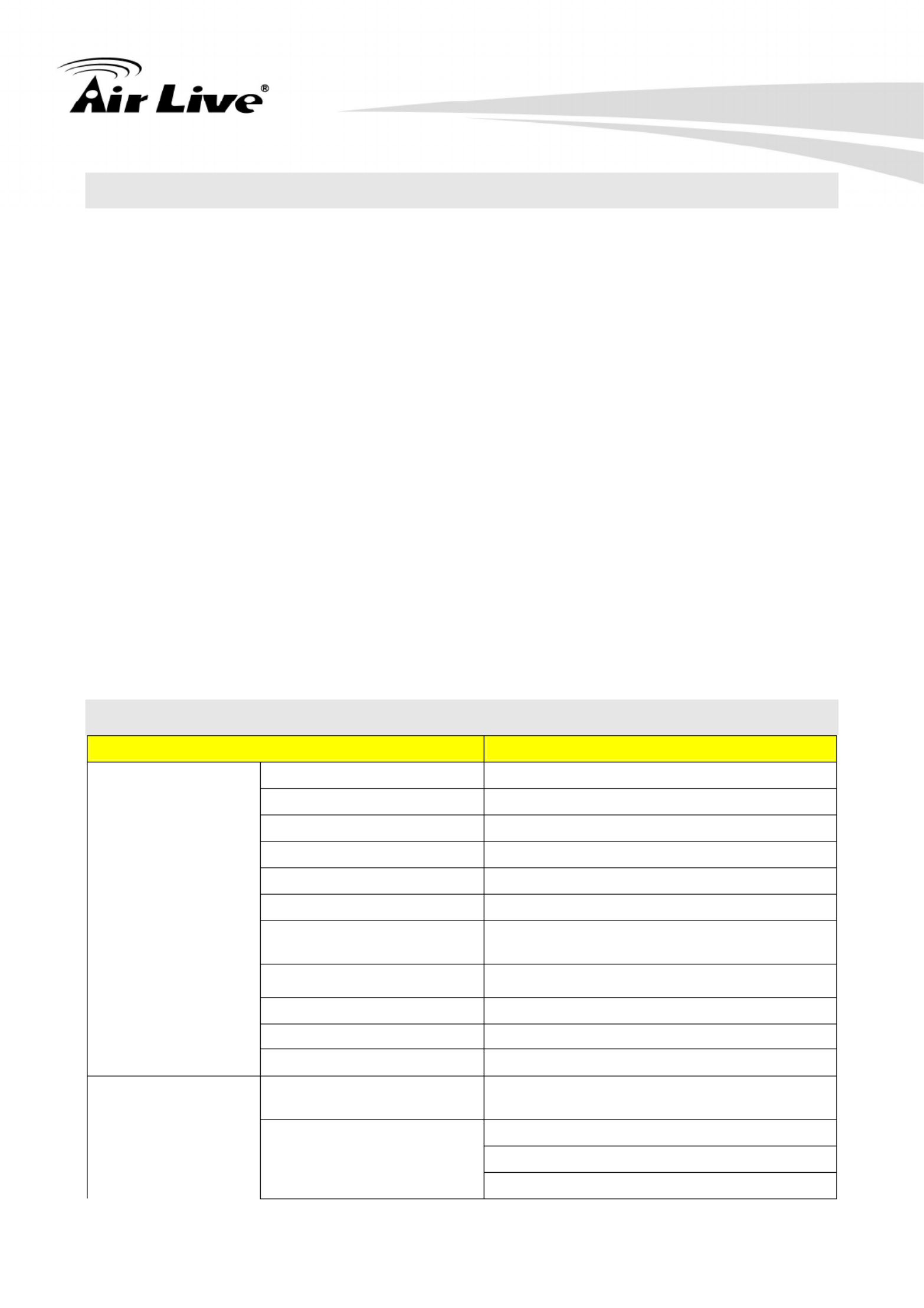
1.3 Product Specification
Model BU-2015
Camera Type Outdoor IR Bullet Type
Image Sensor 1/2.5" CMOS Sensor
Max. Resolution 1920 X 1080
Lens Type 4mm/F1.8, Board Lens
Night Vision Yes
IR Distance (Max.) 15M
Minimum Illumination Color: 0.05 Lux
B/W: 0 Lux (IR On)
Mechanical IR-Cut Filter Yes
Auto Iris None
Viewing Angle D111.5°, H83.7°, V60.6°
Camera
Analog Video Out None
Video Compression H.264 High/Main/Baseline Profile, MPEG4
Simple Profile, MJPEG and 3GPP
30fps@1920x1080
30fps@1280x960
Video
Resolution and Frame
Rate
30fps@1280x720

1. Overview
AirLive BU-2015 User’s Manual
3
30fps@720x480
30fps@640x480
30fps@320x240
Multi-profile streaming
Streaming over UDP, TCP, or HTTP
3GPP mobile view
Configurable frame rate and bandwidth
Streaming
Support CBR and VBR
AE, AWB
Noise reduction
Brightness, Sharpness, Contrast,
Saturation
Mirror Vertical / Horizontal
Image Processing
Text, time and date OSD
Digital Zoom Yes
Shutter Time Auto, Manual: 1/15~1/10000sec,
Day/night dual programmable
Ethernet
One RJ45 Port; IEEE 802.3u Compliant
10/100 Mbps Fast Ethernet with
Auto-MDIX
PoE IEEE802.3af/at
Supported Protocols
TCP/IP, UDP, ICMP, DHCP, NTP, DNS,
DDNS, SMTP, FTP, HTTP, HTTPs,
Samba, PPPoE, UPnP, Bonjour, RTP,
RTSP and RTCP
Password protection
IP filter
Network
Security
HTTPS
Power LED Amber Color
LED Indicator Link/Act. LED Green Color
Network Processor DSP Base
Power Supply DC5V/2A (Optional)
Power Consumption 8 Watts Max.
RJ-45 10BaseT/100BaseTX
5V DC power jack Connector
Reset Button
Operation Temp: -20℃ ~ 50℃
Humidity: 20% ~ 85% non-condensing
Environment Storage Temp: -20℃ ~ 60℃
Humidity: 0% ~ 90% non-condensing
Weather Proof IP66
General
SD card slot 32G MicroSD/SDHC

1. Overview
AirLive BU-2015 User’s Manual 4
Dimension φ73mm x 112mm
CamPro Express 64, CamPro
Professional Software
Search & Installation- IP Wizard II
Event Triggers Motion detection
Motion Detection Up to 3 zones
FTP or NAS file upload
Event handler E-mail alter
UPNP Yes
ONVIF
Open API for software integration
Application Programming
Interface SDK
Video Buffer 5 sec. pre-alarm / 5 sec. post-alarm, up to
3MB
File upload via FTP, NAS, E-mail
Notification via email Alarm Events
Save to SD card
Continuous Recording Yes
System Integration
Certificate CE, FCC-Class A
OS Windows® XP, Vista, 7
Browser IE 6.0 or later, Firefox 2.0 or later, Safari
Cell Phone With 3GPP player
Viewing System
Video Player VLC, Quick Time, Real Player, Core
Player
1.4 System Requirement
For normal operation and viewing of the network camera, it’s recommended that your
system meets these minimum requirements for proper operation:
Item Requirements
CPU Pentium-4 3.6 GHz or higher
VGA Monitor Resolution1280 x 1024 or higher
RAM Minimum 1 GB of RAM
Operating System Window XP, Vista or Windows 7
Web Browser Internet Explorer 7 or later; Apple Safari; Firefox; Google Chrome
Cell Phone 3GPP Player
Note: Please keep updating the latest Windows software and service package.
(Ex: Net Framework, Windows Media Player, Enhance ActiveX Security)

2. Package Contents and Installation
AirLive BU-2015 User’s Manual
5
2 2. Package Contents and
Installation
2.1 Package Content
User can find the following items in the package as below:
1. AirLive BU-2015 is the main element of the product.
2. Bundle CD includes IP Wizard II, CamPro Express64, Quick Start Guide, User Manual,
and Video clips.
3. Quick Start Guide provides important information and instructions for installing this
device.
4. Accessory Package including sunshield, bracket and screws.
Note: The power adapter is optional.
2.2 Connections
Power Source Requirement
This camera can work with 802.3af/at POE switch without the power adapter. However, if
you don’t have POE switch, you can use power adapter to provide power to camera.
Switch/Connector
There are various connectors of AirLive BU-2015 as shown in the figures below.
Please refer to the diagrams and tables accompanied with for using of each switch /
connector.
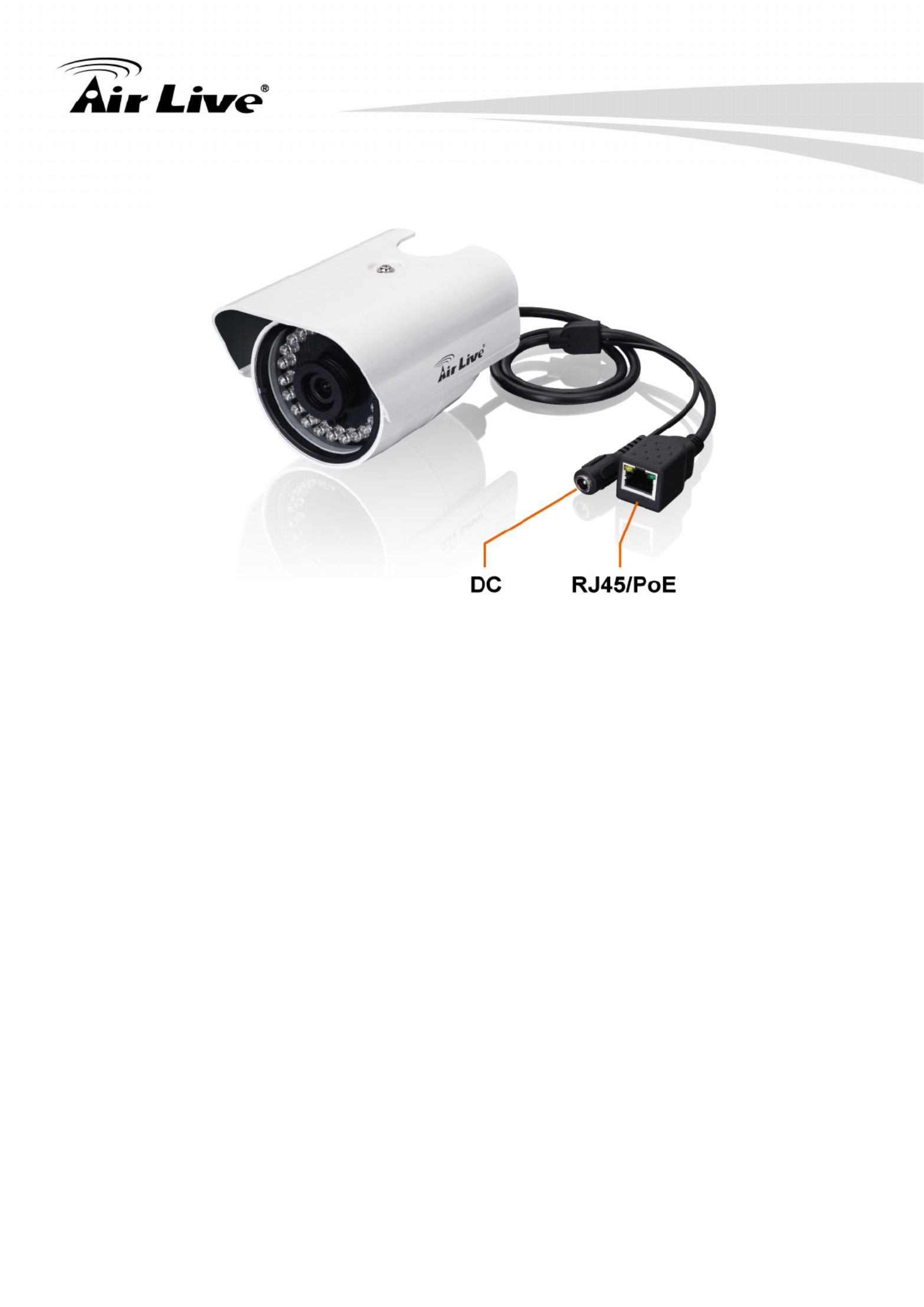
2. Package Contents and Installation
AirLive BU-2015 User’s Manual 6
1. RJ45 LAN socket: Connect to Hub / Switch / PoE Switch / PC.
This Ethernet port built N-Way protocol can detect or negotiate the transmission speed
of the network automatically. Please use Category 5 cable to connect the Network
Camera to a 100Mbps Fast Ethernet network switch or hub.
In the LAN socket, there are two LEDs embedded:
LAN LED (Green color)
Green Link Light indicates the network accessing.
Power (Amber color)
This LED is used to indicate whether DC power/PoE power is on or not.
2. DC-in: The input power is DC5V/2A.

2. Package Contents and Installation
AirLive BU-2015 User’s Manual
7
2.3 Install the Camera
Install the camera in LAN/WAN:
1. Plug an Ethernet cable into the camera
Connect an Ethernet cable to the LAN socket and attach it into the network.
2. Connect the external power supply to camera by power adapter or PoE switch.
3. Remove the front cover to adjust the focus and insert the MicroSD card if necessary.
4. Find the screws in the package to fix the sun shield on top.

2. Package Contents and Installation
AirLive BU-2015 User’s Manual 8
2.4 Connect to IP Camera
1. Insert the bundled CD into your PC/Laptop.
2. Auto Run screen pops up, click “Install Software Æ AirLive IP Wizard II” to install the
configuration tool.
2. Package Contents and Installation
AirLive BU-2015 User’s Manual
9
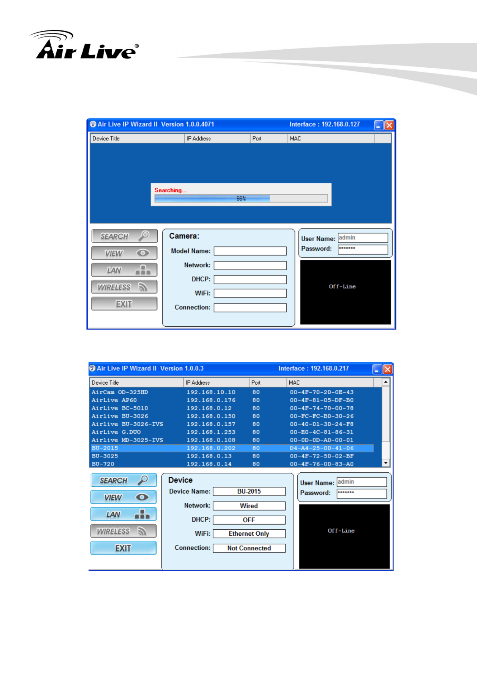
3. After completing installation, run the “Air Live IP Wizard II” to start to search the IP
camera.
4. The entire detected IP camera will be listed out.
5. If the Camera’s IP address is in the same IP segment as your LAN, select the founded IP
Camera and double click on the item. Then, the default browser will show up and connect
to the IP camera’s Web automatically.
3. Using IP Camera via Web Browser
AirLive BU-2015 User’s Manual 10
3 3. Using IP Camera via
Web Browser
3.1 Windows Web Browser
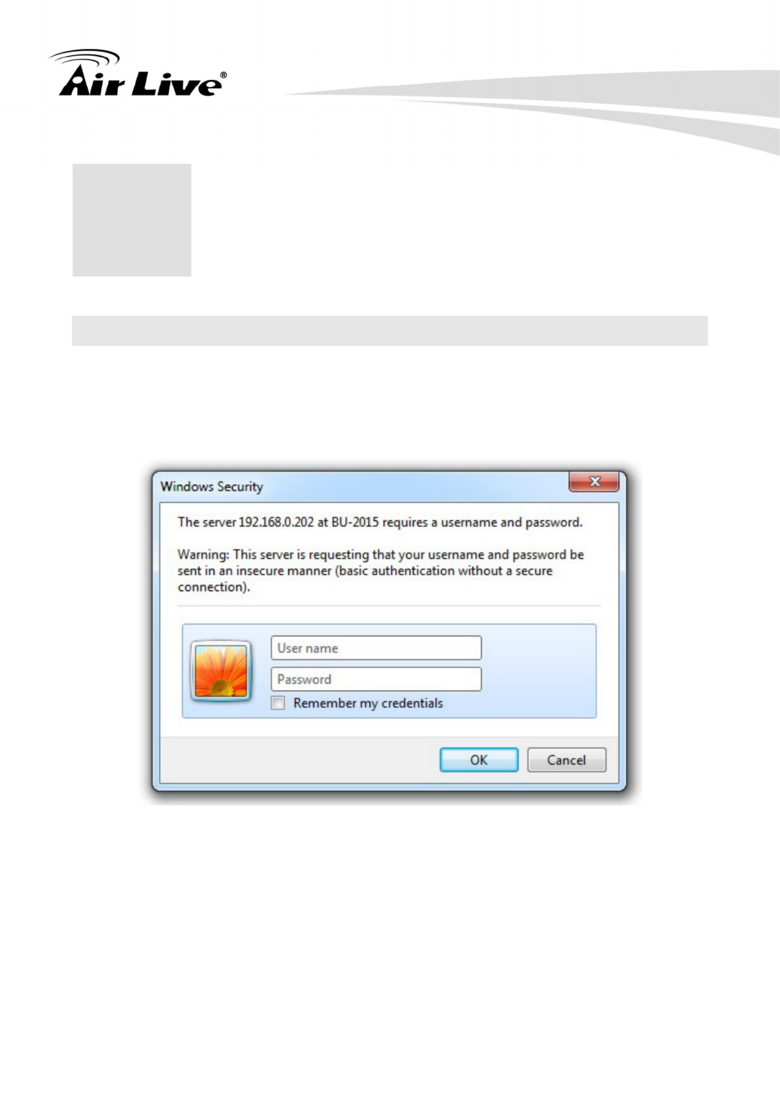
1. Open your web browser and enter the IP address or host name of the IP camera in the
Location / Address field of your browser.
2. Use the default account “admin” and default password “airlive”.
Note: The default user name “admin” and the password “airlive” are the default values.
You can change them in the Security Menu. (Please check “Configuration → Security”)

4. Operating IP Camera via Mobile Phone
AirLive BU-2015 User’s Manual
11
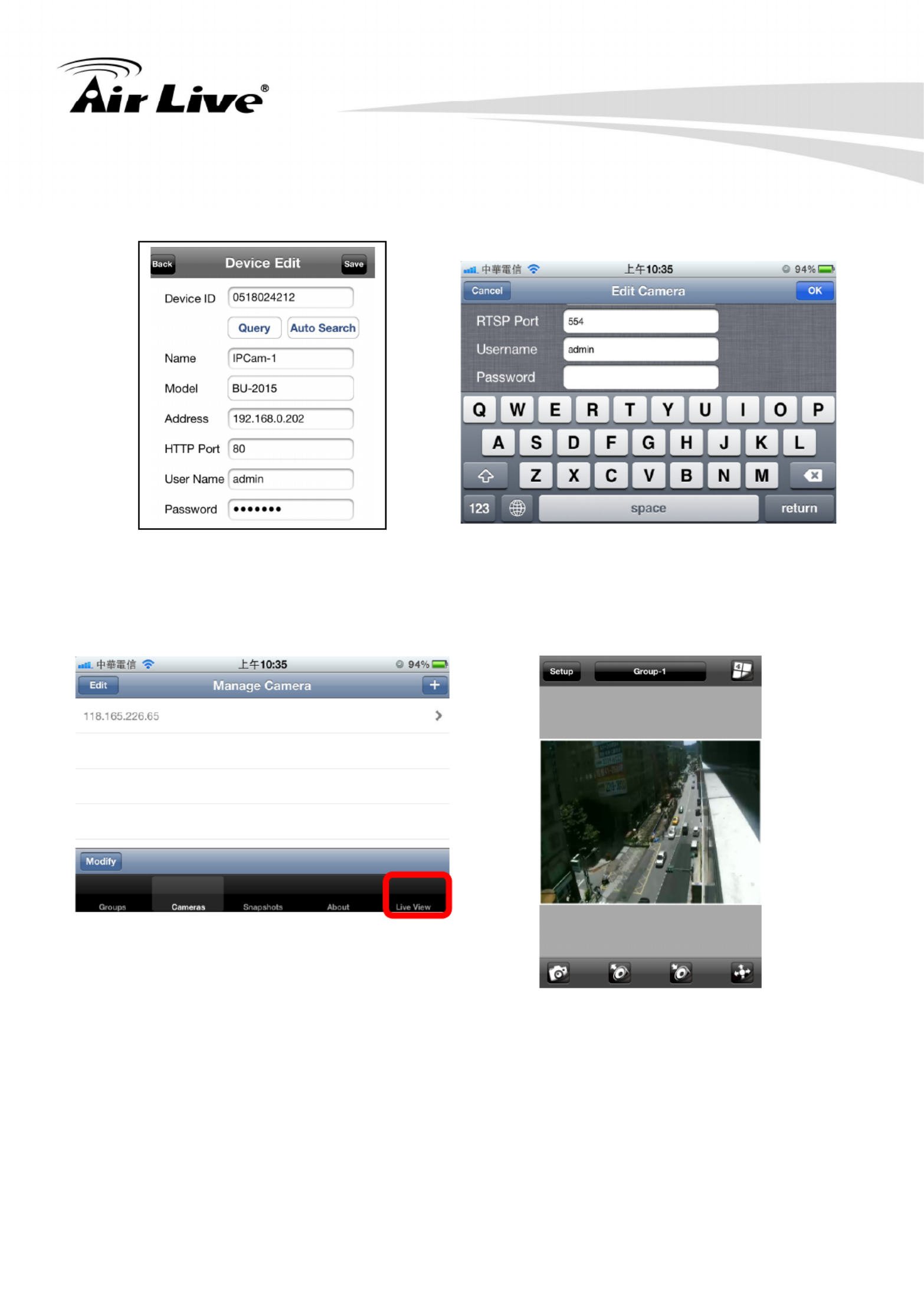
4.1 Using IP Camera via iPhone
You can access to your IP camera via your iPhone. Please follow the setting process below.
Then you can see the live view via iPhone.
4 4. Operating IP Camera
via Mobile Phone
2. Execute AirLive CamPro Mobile
1. Download AirLive CamPro
Mobile from APP store
3. Click Setup button. 4. Setup page appears

4. Operating IP Camera via Mobile Phone
AirLive BU-2015 User’s Manual 12
5. Click Add button.
6.Click LAN button and select the camera.
4. Operating IP Camera via Mobile Phone
AirLive BU-2015 User’s Manual
13
8. Key-in Username and Password
then click OK button.
7. Model, Address, HTTP Port info
appear on the page.
10. The video appears on the main screen.
9. Click Live View button.
Note: The image is continuous snapshots, not video. Thus, live image can’t be
recorded here.

5. Operating the Network Camera
AirLive BU-2015 User’s Manual 14
5 5. Operating the
Network Camera
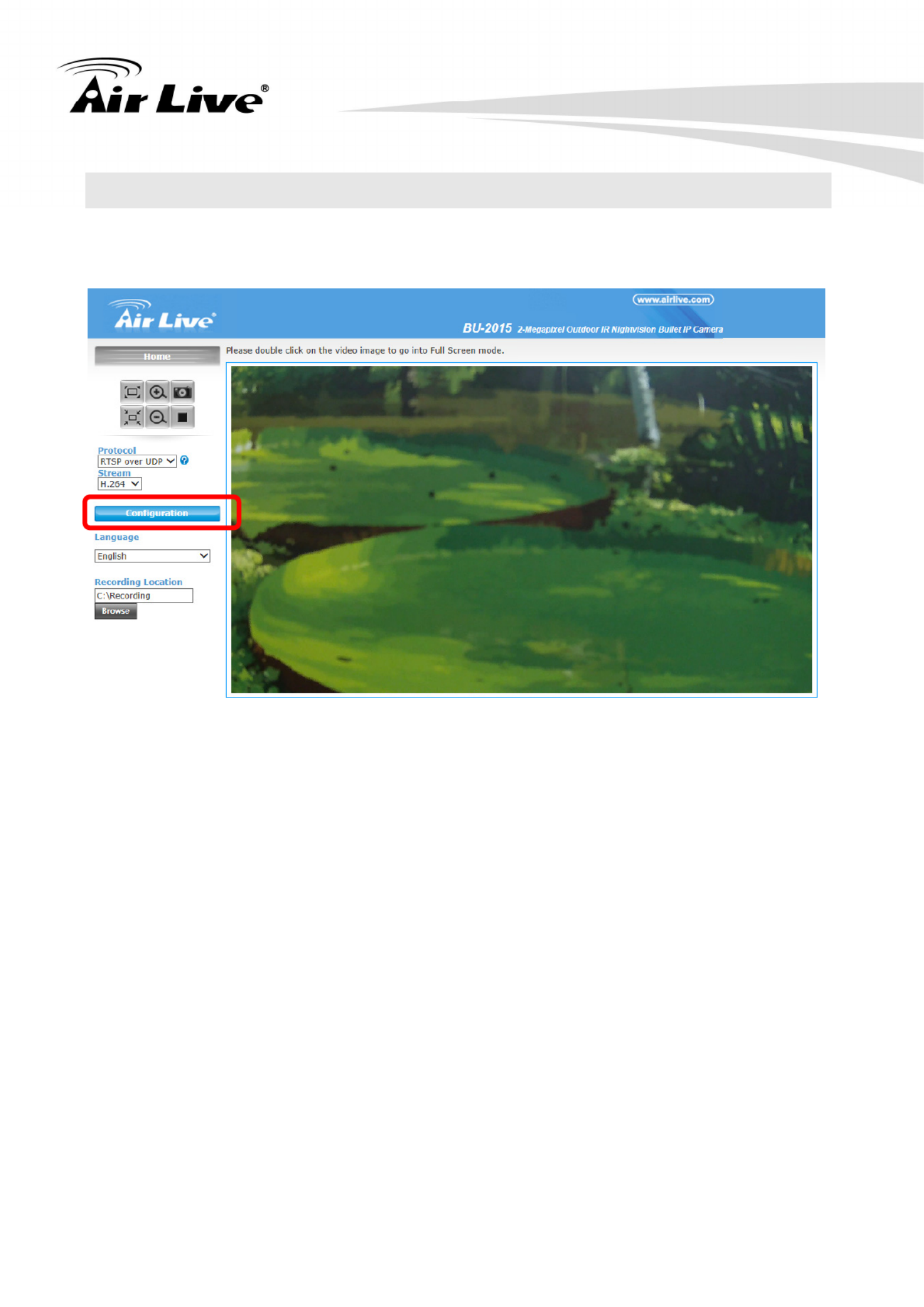
Start-up screen will be shown as follow no matter an ordinary users or an administrator.
In the left side, you can control Live View in your main Browser. Please refer to the
description below:

5. Operating the Network Camera
AirLive BU-2015 User’s Manual
15
5.1 Live View
1. Language
BU-2015 support multi-language, please choose from the pull-down list.
2. Stream
The device supports multi-profile function for H.264, MEPG4 and JPEG simultaneously.
User can choose the proper and/or preferred profile which is listed here.
3. Protocol
A user can select proper streaming protocol according to network environment.
4. Original size / Preview Size
Switches live image view between original size (Depends on main stream setting) and
preview size (smaller size).
5. Digital Zoom
You can see larger objects in video.
Please note: that digital zoom uses computer algorithm to enlarge the video and may
lose some details.
6. Snapshot
Take a snapshot and save images into your computer.
7. Record
Press Record button to start recording. The video file is saved as ASF format into
your local PC. While you want to stop it, press Stop to stop recording.
8. Recording Location
Select the path to save the recording file.
5. Operating the Network Camera
AirLive BU-2015 User’s Manual 16
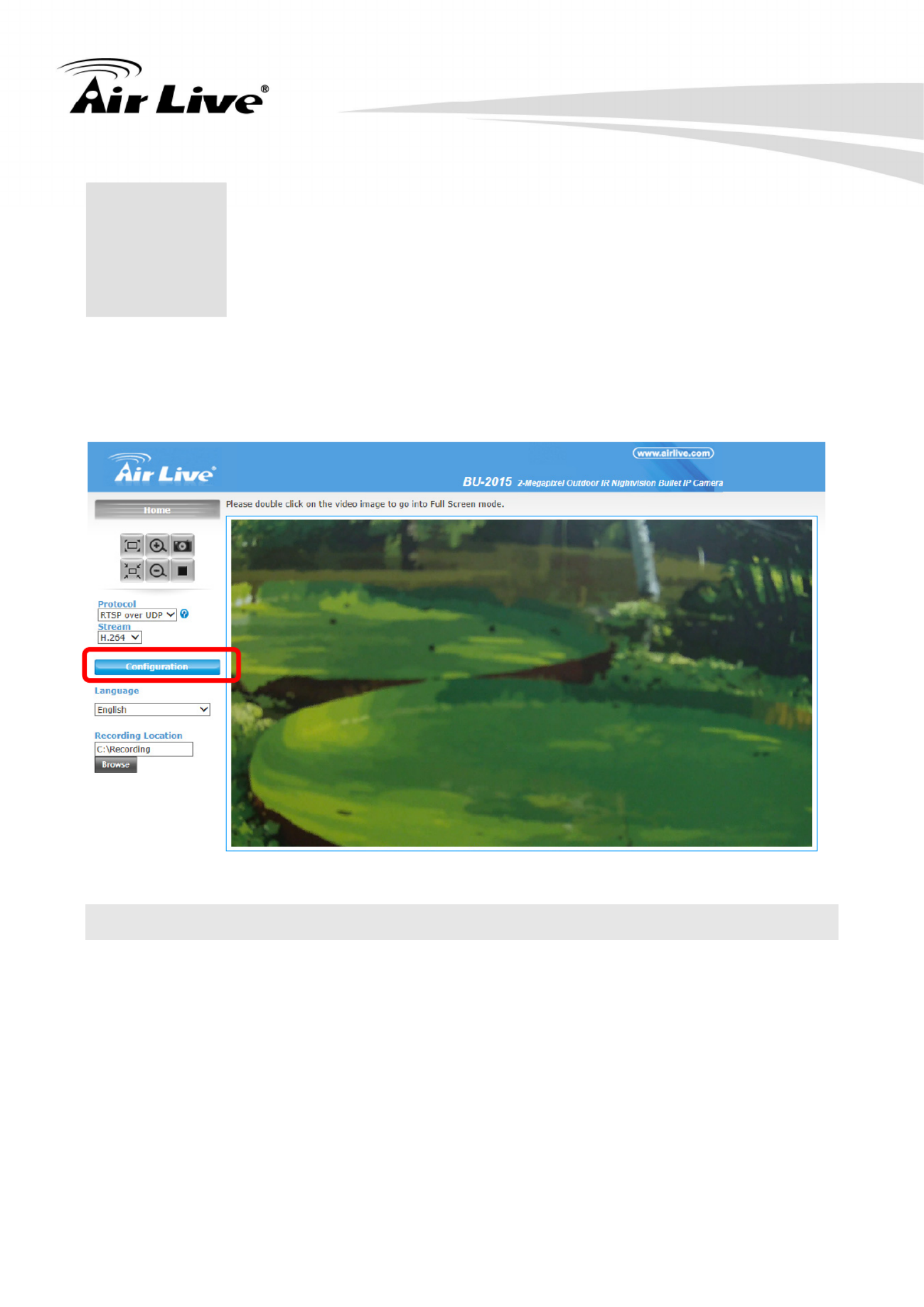
5.2 Configuration
Click “Configuration” for the camera detail settings. For more information, please refer to
Chapter 6.
6. Configuration
AirLive BU-2015 User’s Manual
17
Click the “Configuration” to display sub-menus included:
System / Security / Network / IP Filter / Video / Motion / Event / Recording / SDHC /
Log / Device info / Maintenance
6.1 System
In this menu, you can configure basic IP camera settings here.
1. System
- Host Name
You can enter the name of this unit here. It’s very useful to identify the specific device
from multiple units. The information will be shown on IP Wizard II once the device is
been found.
- Indicator LED
Turn on or off the Indicator LED.
6
6. Configuration

6. Configuration
AirLive BU-2015 User’s Manual 18
2. Date and Time
- Time Zone
Set the time difference from Greenwich Mean Time in the area where the device is
installed.
- Daylight Saving
Disable or enable the daylight saving.
- Keep the current date and time:
Select this option and the date / time setting will not be changed. You can refer to
“Camera Date and Time” item in this page for information.
- Synchronize with computer time
Click this option to enable time synchronization with PC.
- Synchronize with NTP Server
Click this option if you want to synchronize the device with NTP server (Network Time
Protocol).
- Set Manually
Click this option to set time and date manually.
When you finish with above settings, click ‘Apply’ button to save the changes

6. Configuration
AirLive BU-2015 User’s Manual
19
6.2 Security
In this menu, there are three kinds of account that you can configure.
- Administrator
An administrator has highest authority to view and configure all the settings.
For the first time use, input the default value below:
User Name: admin
Password: airlive
- User
User can view IP camera’s video and see settings, but can’t make any change.
- Guest
A guest can view IP camera’s video only.
There can be multiple users, but only one administrator is allowed, and you can’t change
administrator’s user name (it will always be ‘administrator’).
Item Description
Input the new password in both ‘Password’ and ‘Retype Password’
field, and click ‘Modify’ to apply the change.
Password /
Retype Password Please note: You’ll need to reset IP camera’s all settings to get
default password once you forgot the new password.
(Administrator)
Here will list out all existed users. Click ‘Remove’ button to remove
any account.
Account List Note: If no user is existed, ‘New Account’ message will be shown
here.
Input new user’s username here. User name must be greater than 1
character and less than 32 characters.
User Name
Password /
Retype Password
Input this user’s password in both ‘Password’ and ‘Retype Password’
field.
To define the access privilege, select ‘User’ or ‘Guest’ in the
dropdown menu.
Authority
When you finish new user’s information, click ‘New’ button to create a
new user.

6. Configuration
AirLive BU-2015 User’s Manual 20
6.3 Network
1. General
Here are the descriptions of every setup item:
z LAN:
Select this option to assign an IP address to LAN port (or obtain an address from
DHCP server automatically).
Available options are:
- DHCP IPv4: Obtain an IPv4 IP address from DHCP server on LAN automatically.
- DHCP IPv4 / IPv6: Obtain both IPv4 and IPv6 address from DHCP server on LAN
automatically.
- Static IPv4 / IPv6: Assign an IPv4 / IPv6 address to IP camera manually. If you don’t
have a DHCP server on your local area network, you must use this option to specify
an IP address.
- IP Address (IPv4): Input IPv4 IP address*
- IP Address (IPv6): Input IPv6 IP address*
- Prefix Length: Input IPv6 IP address’ prefix length (0 128)

6. Configuration
AirLive BU-2015 User’s Manual
21
- Subnet Mask: Input subnet mask
- Gateway: Input gateway address
- Primary DNS: Input DNS server’s IP address
- Secondary DNS: Input backup DNS server’s IP address, you can leave this field
blank.
* You can leave this field blank, if you only wish to use IPv4 or IPv6 IP address.
Enable UPnP Discovery: Check this box to enable other devices on network to
discover the presence of this IP camera by UPnP. It’s recommended to enable this
function.
Enable UPnP Port Mapping: When UPnP is enabled, check this box to enable UPnP’s
port mapping.
IP Address
(IPv4/IPv6)
Enter the IP address of the camera. The default setting is
192.168.1.100.
Subnet Mask Enter the Subnet Mask of the camera. The default setting is
255.255.255.0.
Default Gateway Enter the Default Gateway of the camera. The default
setting is 192.168.1.254
Primary/
Secondary DNS
DNS (Domain Name System) translates domain names into
IP addresses. Enter the Primary DNS and Secondary DNS
that are provided by ISP.
z PPPoE:
Select this option to use PPPoE to connect to network. You have to input PPPoE
username and password assigned by network operator to get connected.
z HTTP Port:
Input IP camera’s web connection port number here. When this port number is
changed, you need to change web browser’s port number you used to connect to IP
camera.
For example, if the IP camera’s IP address is 192.168.2.3 and you changed HTTP port
number to 82, please input ‘http: //192.168.2.3:82’ in web browser’s address bar to
access IP camera’s web configuration interface.
z RTSP Port:
Input RTSP port number. When this port number changes, you must change
corresponding settings in external network devices (NVR or CMS software) so they
can receive this IP camera’s video.

6. Configuration
AirLive BU-2015 User’s Manual 22
z RTP Data Port:
Input RTP data port number here.
When you finish with above settings, click ‘Apply’ button to save changes.
2. Advanced
You can setup advanced network settings in this page. This page is intended for
advanced settings only, and this IP camera will work fine even you don’t make any
changes to this page.
z Multicast:
Enable video multicast:
Multicast Group Address: Input multicast group address here, must be an address
between 232.0.0.0 to 232.255.255.255.
Multicast video port: Input port number for video multicast here.
Multicast RCTP video port: Input port number for RCTP video here.
Multicast audio port: Input port number for audio here.
Multicast RCTP audio port: Input port number for RCTP audio here.
Multicast TTL: Input TTL value for multicast here.
z Bonjour:
If you’re using Mac OS and you have Bonjour installed, you can use it to discover this
IP camera.
z QoS:
Enable QoS to improve the data transfer priority of this IP camera (Your local area
network must support QoS).
You can select Video / Audio’s QoS DSCP value (0 to 63), or both video and audio.
z DDNS:
Enable DDNS support if your ISP assigns dynamic IP address to you. You must
register a dynamic IP service first. Currently this IP camera supports Dyndns and
TZO dynamic IP service.
Provider: Select dynamic IP service provider.
Host Name: Input the host name you obtained from dynamic IP service provider.
User name: Input user name used to login dynamic IP service provider.
Password: Input the password used to login dynamic IP service provider.
z DIPS ID:
It’s a unique number of each device for identification and this ID is used for DIPS. This
function now is reserved for future use.

6. Configuration
AirLive BU-2015 User’s Manual
23
z HTTPS:
Check ‘Enable HTTPS’ box to enable HTTPS channel to encrypt transferred data.
You can also define HTTPS port number in ‘HTTPS Port’ field if you don’t want to use
default value ‘443’.
6.4 IP Filter
When this IP camera is directly connected to Internet and not protected by firewall, this
function acts like a mini built in firewall to protect the safety of this IP camera and avoid
attacks from hackers.
Item Description
Enable Filter Check this box to enable IP address filter, uncheck this box to disable
this function.
Accepted IP list Here lists all IP address that can build connections to this IP camera.
If you want to remove a set of IP address from the list, click on the IP
address and click ‘Remove’ button.
IP Address
(Accepted IP list)
Input the starting and ending IP address of IP address you wish to
accept connections here. IP camera will only accept connections
established from these IP address.

6. Configuration
AirLive BU-2015 User’s Manual
25
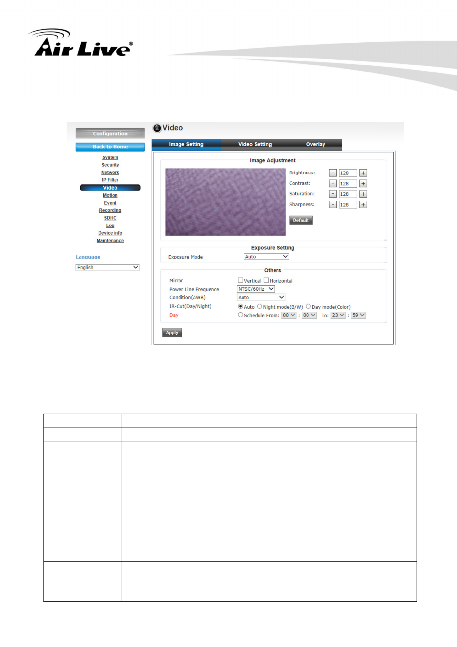
6.5 Video
1. Image Setting
You can adjust the image parameters in this page.
z Brightness /Contrast /Saturation /Sharpness:
Control the image parameters. Click ‘ ‘ to decrease value, or click ‘ + ‘ to increase
value. You can also input the value in the field directly.
z Exposure Setting:
1. Manual: You can setup more details here including Exposure Value, Exposure Time
and Gain.
2. Exposure Value is from 0~255
3. Exposure Time range is about Auto, 1/15, 100, 1/120, 1/250, 1/30, 1/50, 1/60, 1/
1/500, 1/1000, 1/2000, 1/4000, 1/10000.
4. Gain value is from 0~8
5. Auto: Camera will adjust the exposure automatically.
z Mirror:
Check “Vertical” and “Horizontal” box to flip the image vertically or horizontally.
z Power Line Frequency:
Select the frequency of power line of the place you’re using this IP camera. This will
help to reduce the flicker of certain lights in the image.
z Condition(AWB):
Select the condition that you’ll be using this IP camera from dropdown menu.
Auto: IP camera will adjust its parameters automatically.
Indoor, B/W, Tungsten: IP camera will adjust its parameters by different environment.
z IR cut:
An IR cut filter is built in this IP camera to reduce the effect of IR lights (which will
change the color of image and makes it looks different than what you see through your
eyes), and most of IR lights are coming from sunlight.
You can select the behavior or IR cut filter:
Auto: IR filter will act automatically. If you don't know wheatear you should use IR
filter or not, select this option.
Night mode (B/W): IR filter is always on.
Day mode (Color): IR filter is always off.
6. Configuration
AirLive BU-2015 User’s Manual 26
z Day:
Select the time that you want to keep the day mode.
2. Video Setting
You can adjust the video transfer parameters in this page.
Here are the descriptions of every setup item:
Item Description
H.264 /MPEG4 Select the compression of main stream: H.264 / MPEG4.
Video Resolution Select video resolution.
‐ H.264:
1920x1080 (1080p) / 1280x960 (960p) / 1280x720 (720p)
720x480 (D1) / 640x480 (VGA) / 320x240 (QVGA)
‐ MPEG4:
1920x1080 (1080p) / 1280x960 (960p) / 1280x720 (720p)
720x480 (D1) / 640x480 (VGA) / 320x240 (QVGA)
‐ MJPEG:
720x480 (D1) / 640x480 (VGA) / 320x240 (QVGA)
Frame Rate Select video frame rate.
When network speed is insufficient, select a lower frame rate will help.
Product specificaties
| Merk: | Airlive |
| Categorie: | Bewakingscamera |
| Model: | BU-2015 |
| Kleur van het product: | Wit |
| Soort: | IP-beveiligingscamera |
| Internationale veiligheidscode (IP): | IP66 |
| Maximale capaciteit van de geheugenkaart: | 32 GB |
| Ondersteunde videoformaten: | H.264, MPEG4 |
| Vormfactor: | Rond |
| Ondersteuning voor plaatsing: | Buiten |
| Connectiviteitstechnologie: | Bedraad |
| Ethernet LAN: | Ja |
| Ondersteunde video-modi: | 1080p |
| Maximum resolutie: | 1920 x 1080 Pixels |
| Totaal aantal megapixels: | 2 MP |
| Diameter: | 73 mm |
| Type stroombron: | Power over Ethernet (PoE) |
| Stroomuitvoer (ampère): | 2 A |
| Minimale belichting: | 0.05 Lux |
| Geïntegreerde geheugenkaartlezer: | Ja |
| Compatibele geheugenkaarten: | MicroSD (TransFlash), MicroSDHC |
| Ingebouwde HDD: | Nee |
| Nachtvisie: | Ja |
| LED-type: | IR |
| HTTPS-encryptie: | Ja |
| Omvang optische sensor: | 1/2.5 " |
| Aansluiting voor netstroomadapter: | Ja |
| Type beeldsensor: | CMOS |
| Optische zoom: | - x |
| Camera sluitertijd: | 0.0001 - 0.066 s |
| Ondersteunde grafische resoluties: | 320 x 240,720 x 480,1280 x 960,1280 x 720 (HD 720),1920 x 1080 (HD 1080),640 x 480 (VGA) |
| Bekabelingstechnologie: | 10/100Base-T(X) |
| Ondersteunt Windows: | Ja |
| Lengte: | 112 mm |
| Temperatuur bij opslag: | -20 - 60 °C |
| Maximaal 30 frames per seconde: | 30 fps |
| Ondersteunde netwerkprotocollen: | TCP/IP, UDP, ICMP, DHCP, NTP, DNS, DDNS, SMTP, FTP, HTTP, HTTPs, Samba, PPPoE, UPnP, Bonjour, RTP, RTSP, RTCP |
| Luchtvochtigheid bij opslag: | 0 - 90 procent |
| Reset button: | Ja |
| IP-adresfilter: | Ja |
| Power over Ethernet (PoE): | Ja |
| PTZ control: | Nee |
| Dag/nacht modus: | Ja |
| Nachtkijker afstand: | 15 m |
| Wifi: | Nee |
| AC-ingangsspanning: | 5 V |
| Stroomverbruik (typisch): | 8 W |
| Bedrijfstemperatuur (T-T): | -20 - 50 °C |
| Relatieve vochtigheid in bedrijf (V-V): | 20 - 85 procent |
| Kijkhoek lens, horizontaal: | 83.7 ° |
| Kijkhoek lens, verticaal: | 60.6 ° |
Heb je hulp nodig?
Als je hulp nodig hebt met Airlive BU-2015 stel dan hieronder een vraag en andere gebruikers zullen je antwoorden
Handleiding Bewakingscamera Airlive

12 Maart 2025
12 Maart 2025
12 Maart 2025
12 Maart 2025
12 Maart 2025
12 Maart 2025
9 Juli 2023
21 Juni 2023
21 Juni 2023
19 Juni 2023
Handleiding Bewakingscamera
- Bewakingscamera Braun
- Bewakingscamera Bosch
- Bewakingscamera Philips
- Bewakingscamera Sony
- Bewakingscamera Samsung
- Bewakingscamera Xiaomi
- Bewakingscamera Panasonic
- Bewakingscamera Asus
- Bewakingscamera Canon
- Bewakingscamera Garmin
- Bewakingscamera Grundig
- Bewakingscamera Gigaset
- Bewakingscamera Honeywell
- Bewakingscamera JVC
- Bewakingscamera Motorola
- Bewakingscamera Pioneer
- Bewakingscamera Toshiba
- Bewakingscamera VTech
- Bewakingscamera Abus
- Bewakingscamera ACME
- Bewakingscamera Acti
- Bewakingscamera Ag Neovo
- Bewakingscamera Aldi
- Bewakingscamera Alecto
- Bewakingscamera Allnet
- Bewakingscamera Aluratek
- Bewakingscamera Anker
- Bewakingscamera Apc
- Bewakingscamera Aqara
- Bewakingscamera Aritech
- Bewakingscamera Avanti
- Bewakingscamera AVTech
- Bewakingscamera Axis
- Bewakingscamera Beafon
- Bewakingscamera Belkin
- Bewakingscamera Blaupunkt
- Bewakingscamera Boss
- Bewakingscamera Brinno
- Bewakingscamera BRK
- Bewakingscamera Buffalo
- Bewakingscamera Burg-Wachter
- Bewakingscamera D-Link
- Bewakingscamera Dedicated Micros
- Bewakingscamera Denver
- Bewakingscamera Digitus
- Bewakingscamera DIO
- Bewakingscamera Dorr
- Bewakingscamera E-bench
- Bewakingscamera Ebode
- Bewakingscamera Edimax
- Bewakingscamera Ednet
- Bewakingscamera Elmo
- Bewakingscamera Elro
- Bewakingscamera Eminent
- Bewakingscamera Engenius
- Bewakingscamera Eufy
- Bewakingscamera EverFocus
- Bewakingscamera Extech
- Bewakingscamera Ezviz
- Bewakingscamera Ferguson
- Bewakingscamera First Alert
- Bewakingscamera Flamingo
- Bewakingscamera Flir
- Bewakingscamera Foscam
- Bewakingscamera Friedland
- Bewakingscamera Ganz
- Bewakingscamera Gembird
- Bewakingscamera Genius
- Bewakingscamera GeoVision
- Bewakingscamera Gira
- Bewakingscamera Google
- Bewakingscamera Grandstream
- Bewakingscamera Hama
- Bewakingscamera Hikvision
- Bewakingscamera Iget
- Bewakingscamera Iiquu
- Bewakingscamera Iluv
- Bewakingscamera Indexa
- Bewakingscamera InFocus
- Bewakingscamera Interlogix
- Bewakingscamera Ion
- Bewakingscamera Kerbl
- Bewakingscamera KlikaanKlikuit
- Bewakingscamera Kodak
- Bewakingscamera Kogan
- Bewakingscamera Konig
- Bewakingscamera Laserliner
- Bewakingscamera LevelOne
- Bewakingscamera Linksys
- Bewakingscamera Logilink
- Bewakingscamera Logitech
- Bewakingscamera Lorex
- Bewakingscamera Maginon
- Bewakingscamera Manhattan
- Bewakingscamera Marmitek
- Bewakingscamera Marquant
- Bewakingscamera Marshall
- Bewakingscamera Megasat
- Bewakingscamera Minox
- Bewakingscamera Mitsubishi
- Bewakingscamera Monacor
- Bewakingscamera Nedis
- Bewakingscamera Nest
- Bewakingscamera Netatmo
- Bewakingscamera Netgear
- Bewakingscamera Netis
- Bewakingscamera Notifier
- Bewakingscamera Perel
- Bewakingscamera Powerfix
- Bewakingscamera Profile
- Bewakingscamera Provision ISR
- Bewakingscamera Pyle
- Bewakingscamera Quantum
- Bewakingscamera Raymarine
- Bewakingscamera Renkforce
- Bewakingscamera Revo
- Bewakingscamera Ricoh
- Bewakingscamera Ring
- Bewakingscamera Rollei
- Bewakingscamera Sanyo
- Bewakingscamera Satel
- Bewakingscamera Schneider
- Bewakingscamera SecurityMan
- Bewakingscamera Siedle
- Bewakingscamera Sitecom
- Bewakingscamera Smartwares
- Bewakingscamera SMC
- Bewakingscamera Somfy
- Bewakingscamera Sonic Alert
- Bewakingscamera Stabo
- Bewakingscamera Strong
- Bewakingscamera Switel
- Bewakingscamera Synology
- Bewakingscamera Technaxx
- Bewakingscamera Tenda
- Bewakingscamera Thomson
- Bewakingscamera TP Link
- Bewakingscamera Trebs
- Bewakingscamera Trendnet
- Bewakingscamera Trust
- Bewakingscamera Uniden
- Bewakingscamera V-Tac
- Bewakingscamera Velleman
- Bewakingscamera Vitek
- Bewakingscamera Vivotek
- Bewakingscamera Waeco
- Bewakingscamera Western Digital
- Bewakingscamera Withings
- Bewakingscamera Woonveilig
- Bewakingscamera Xavax
- Bewakingscamera Y-cam
- Bewakingscamera Yale
- Bewakingscamera Zebra
- Bewakingscamera ZTE
- Bewakingscamera ZyXEL
- Bewakingscamera Jung
- Bewakingscamera Olympia
- Bewakingscamera Oplink
- Bewakingscamera Orion
- Bewakingscamera Overmax
- Bewakingscamera Clas Ohlson
- Bewakingscamera Caliber
- Bewakingscamera Exibel
- Bewakingscamera Monoprice
- Bewakingscamera Naxa
- Bewakingscamera Niceboy
- Bewakingscamera Schwaiger
- Bewakingscamera Steren
- Bewakingscamera Ubiquiti Networks
- Bewakingscamera EMOS
- Bewakingscamera Conceptronic
- Bewakingscamera Miniland
- Bewakingscamera Arlo
- Bewakingscamera Atlona
- Bewakingscamera Avidsen
- Bewakingscamera Hamlet
- Bewakingscamera Hive
- Bewakingscamera Imou
- Bewakingscamera INSTAR
- Bewakingscamera SereneLife
- Bewakingscamera Defender
- Bewakingscamera Trevi
- Bewakingscamera Adesso
- Bewakingscamera Broan
- Bewakingscamera DSC
- Bewakingscamera M-e
- Bewakingscamera Blow
- Bewakingscamera Genie
- Bewakingscamera ClearOne
- Bewakingscamera Chacon
- Bewakingscamera Swann
- Bewakingscamera Approx
- Bewakingscamera SPC
- Bewakingscamera Canyon
- Bewakingscamera Cisco
- Bewakingscamera EVOLVEO
- Bewakingscamera Whistler
- Bewakingscamera Delta Dore
- Bewakingscamera Furrion
- Bewakingscamera Comtrend
- Bewakingscamera Planet
- Bewakingscamera Blink
- Bewakingscamera Intellinet
- Bewakingscamera Aida
- Bewakingscamera Lindy
- Bewakingscamera AVerMedia
- Bewakingscamera Lumens
- Bewakingscamera Mobi
- Bewakingscamera Fortinet
- Bewakingscamera DataVideo
- Bewakingscamera Hombli
- Bewakingscamera Vaddio
- Bewakingscamera Adj
- Bewakingscamera Ikan
- Bewakingscamera Dahua Technology
- Bewakingscamera UniView
- Bewakingscamera Reolink
- Bewakingscamera Valueline
- Bewakingscamera EVE
- Bewakingscamera QSC
- Bewakingscamera Marshall Electronics
- Bewakingscamera Boyo
- Bewakingscamera IC Intracom
- Bewakingscamera CRUX
- Bewakingscamera POSline
- Bewakingscamera August
- Bewakingscamera Hawking Technologies
- Bewakingscamera Lanberg
- Bewakingscamera Nexxt
- Bewakingscamera Watec
- Bewakingscamera Moog
- Bewakingscamera Equip
- Bewakingscamera Crestron
- Bewakingscamera Chuango
- Bewakingscamera ORNO
- Bewakingscamera ETiger
- Bewakingscamera Videcon
- Bewakingscamera Advantech
- Bewakingscamera Moxa
- Bewakingscamera Digital Watchdog
- Bewakingscamera Brilliant
- Bewakingscamera Moen
- Bewakingscamera Kramer
- Bewakingscamera MEE Audio
- Bewakingscamera Brickcom
- Bewakingscamera Kwikset
- Bewakingscamera Linear PRO Access
- Bewakingscamera BirdDog
- Bewakingscamera AVer
- Bewakingscamera Summer Infant
- Bewakingscamera Topica
- Bewakingscamera Vimar
- Bewakingscamera Speco Technologies
- Bewakingscamera Verint
- Bewakingscamera ZKTeco
- Bewakingscamera Rostra
- Bewakingscamera Kguard
- Bewakingscamera Caddx
- Bewakingscamera Spyclops
- Bewakingscamera EKO
- Bewakingscamera Inovonics
- Bewakingscamera Surveon
- Bewakingscamera Hollyland
- Bewakingscamera Epcom
- Bewakingscamera AViPAS
- Bewakingscamera Lutec
- Bewakingscamera Hanwha
- Bewakingscamera ClearView
- Bewakingscamera VideoComm
- Bewakingscamera IMILAB
- Bewakingscamera InfiRay
- Bewakingscamera 3xLOGIC
- Bewakingscamera Pelco
- Bewakingscamera Leviton
- Bewakingscamera EtiamPro
- Bewakingscamera Inkovideo
- Bewakingscamera Pentatech
- Bewakingscamera Weldex
- Bewakingscamera CNB Technology
- Bewakingscamera Tapo
- Bewakingscamera Aigis
- Bewakingscamera Exacq
- Bewakingscamera Laxihub
- Bewakingscamera Securetech
- Bewakingscamera EFB Elektronik
- Bewakingscamera Ernitec
- Bewakingscamera NetMedia
- Bewakingscamera Videotec
- Bewakingscamera Illustra
- Bewakingscamera AVMATRIX
- Bewakingscamera Nivian
- Bewakingscamera Arenti
- Bewakingscamera Syscom
- Bewakingscamera Tecno
- Bewakingscamera Night Owl
- Bewakingscamera Guardzilla
- Bewakingscamera Astak
- Bewakingscamera Milestone Systems
- Bewakingscamera Zavio
- Bewakingscamera Campark
- Bewakingscamera IPX
- Bewakingscamera Promise Technology
- Bewakingscamera Annke
- Bewakingscamera Qoltec
- Bewakingscamera Digimerge
- Bewakingscamera Alfatron
- Bewakingscamera Feelworld
- Bewakingscamera KJB Security Products
- Bewakingscamera British Telecom
- Bewakingscamera Wisenet
- Bewakingscamera Ecobee
- Bewakingscamera BZBGear
- Bewakingscamera WyreStorm
- Bewakingscamera Infortrend
- Bewakingscamera Epiphan
- Bewakingscamera HiLook
- Bewakingscamera Mach Power
- Bewakingscamera Compro
- Bewakingscamera Ikegami
- Bewakingscamera Accsoon
- Bewakingscamera Vimtag
- Bewakingscamera Sonoff
- Bewakingscamera Gewiss
- Bewakingscamera Alula
- Bewakingscamera Insteon
- Bewakingscamera Costar
- Bewakingscamera ALC
- Bewakingscamera Security Labs
- Bewakingscamera American Dynamics
- Bewakingscamera Seneca
- Bewakingscamera Avigilon
- Bewakingscamera Vosker
- Bewakingscamera Sentry360
- Bewakingscamera Bea-fon
- Bewakingscamera Owltron
- Bewakingscamera Petcube
- Bewakingscamera Enabot
- Bewakingscamera Luis Energy
- Bewakingscamera Sir Gawain
- Bewakingscamera VisorTech
- Bewakingscamera Atlantis Land
- Bewakingscamera B & S Technology
- Bewakingscamera I3International
- Bewakingscamera IDIS
- Bewakingscamera Turing
- Bewakingscamera Qian
- Bewakingscamera Wasserstein
- Bewakingscamera Qolsys
- Bewakingscamera Control4
- Bewakingscamera Milesight
- Bewakingscamera GVI Security
- Bewakingscamera Conbrov
- Bewakingscamera HuddleCamHD
- Bewakingscamera Setti+
- Bewakingscamera Mobotix
- Bewakingscamera IOIO
- Bewakingscamera BIRDFY
- Bewakingscamera I-PRO
- Bewakingscamera DVDO
- Bewakingscamera TCP
- Bewakingscamera Bolin Technology
- Bewakingscamera Konyks
- Bewakingscamera Nextech
- Bewakingscamera Arecont Vision
- Bewakingscamera YoloLiv
Nieuwste handleidingen voor Bewakingscamera
2 April 2025
30 Maart 2025
29 Maart 2025
29 Maart 2025
29 Maart 2025
29 Maart 2025
29 Maart 2025
27 Maart 2025
27 Maart 2025
27 Maart 2025