Simrad Sensor Handleiding


Lees hieronder de šŸ“– handleiding in het Nederlandse voor Simrad Sensor (4 pagina's) in de categorie Niet gecategoriseerd. Deze handleiding was nuttig voor 13 personen en werd door 2 gebruikers gemiddeld met 4.5 sterren beoordeeld

Pagina 1/4
Sensor Setup Guide
Sensor Setup Guide
| 1
*988-11035-002*
This document describes the setup for the following sensors:
ā€¢ Fluid Level Sensor ā€“ tank levels for fuel*, water, gray water, live well, oil, and black water
ā€¢ Fuel Flow Sensor ā€“ ļ¬‚ow rate measurements of fuel for gasoline powered boats
ā€¢ Fuel Data Manager ā€“ fuel used data from fuel ļ¬‚ow messages it receives from up to three
NMEA 2000 compatible engines
ā€¢ Temperature Sensor ā€“ temperatures for water*, outside, inside, engine room, cabin, live well,
bait well, refrigeration, and heating system
ā€¢ Thru-Hull Temperature Sensor - temperatures for water*, outside, inside, engine room, cabin,
live well, bait well, refrigeration, and heating system
ā€¢ Speed Sensor ā€“ boat speed
ā€¢ Pressure Sensor ā€“ pressure data: Engine Boost Pressure, Engine Oil Pressure, Engine Water
Pressure*, Transmission Oil Pressure and Pitot Speed
* Sensor is pre-conļ¬gured to display this information.
Ā¼Note: The sensor must be installed and connected to the NMEA 2000 network. For installation
and connection information, refer to the installation guide for the sensor.
After the sensor is connected, you can display sensor data. For more information, refer to your
display operating manual.
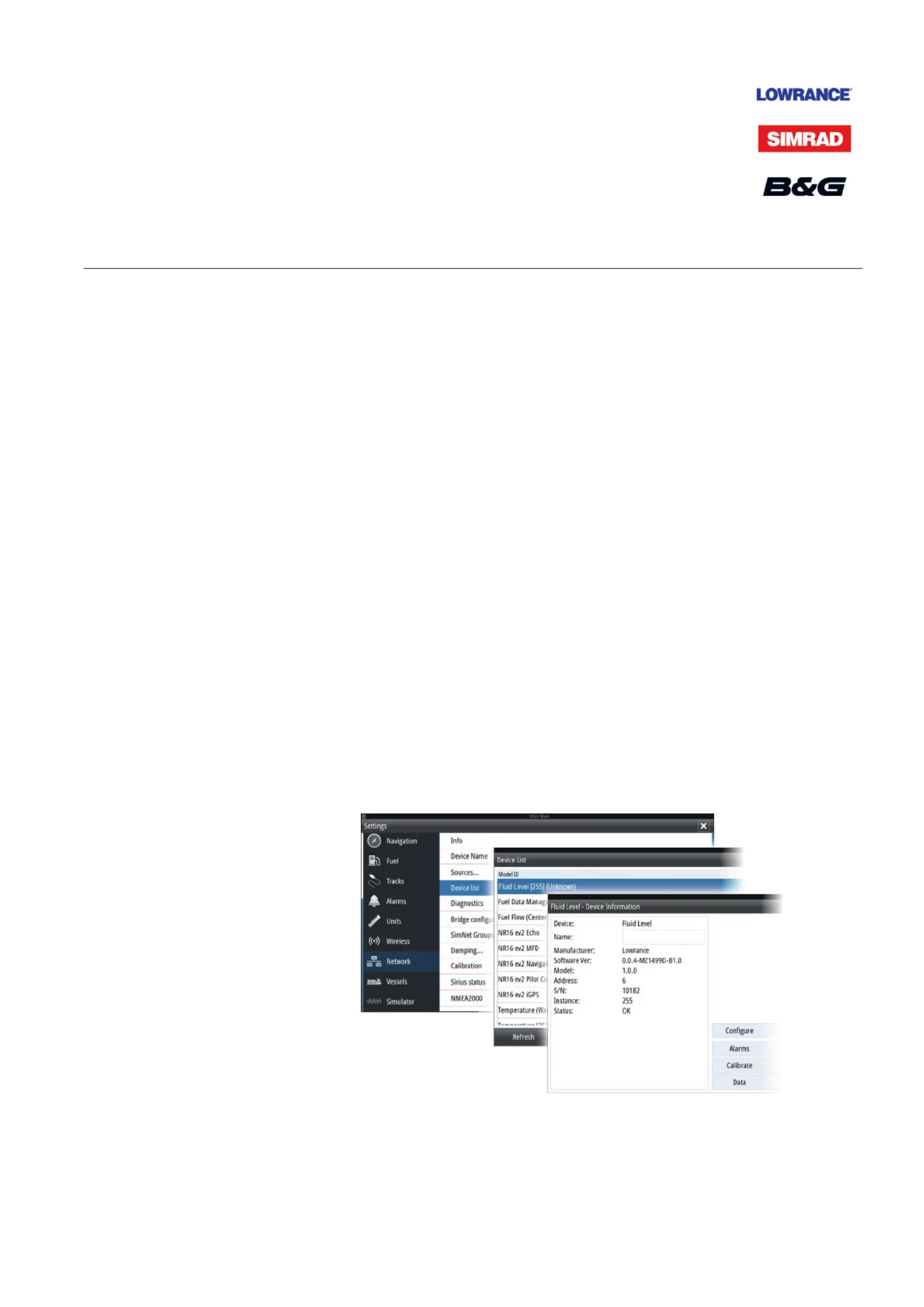
Sensor Setup
Use the Device Information dialog to set the device name, conļ¬gure, view sensor data, and
for some sensors calibrate and set alarms.
Select the sensor in the Device List to display the sensor Device Information dialog. The
following example shows selecting the Fluid Level sensor from a Simrad NSS Evo2.
2 | Sensor Setup Guide
Conī˜Ÿguration
Select the Conļ¬gure button in the Device Information dialog to open the conļ¬guration
dialog.
Use the conļ¬guration dialog to conļ¬gure speciļ¬cs. For example, use the Fluid Level ā€“ Device
conļ¬guration dialog to specify the:
ā€¢ Tank (1, 2, 3, 4, or 5)
ā€¢ Fluid type
ā€¢ Size of the tank
ā€¢ Instance - the Instance is determined by the conļ¬guration process and should not require
user adjustment, except in the case of the Fuel Data Manager. The Fuel Data Manger can work
with up to 3 engines. If more than 3 engines are mounted on the vessel, the instance of the
second Fuel Data Manager will need to be manually changed from 0 to 1.
ā€¢ Unconļ¬gure - sets all the values of the selected sensor to the factory default settings
Calibration
The Fluid Level and Fuel Flow sensors can be calibrated from the Device Information dialog.
Fluid Level sensor calibration
The factory calibration settings for the Fluid Level sensor should be adequate for most
applications, but if your tank has an irregular shape, your tank ļ¬‚oat uses a diļ¬€erent resistance
range other than the U.S. standard of 240-33 Ohms, or if greater accuracy is needed,
calibration is recommended. We recommend starting calibration with an empty tank; you will
ļ¬ll the tank to complete the calibration process.
Select the Calibrate button in the Fluid Level - Device Information dialog to open the
calibration dialog. Select the calibration point and then the fuel level for the point, as you ļ¬ll
your tank. There are three calibration options:
ā€¢ 2-point calibration - for rectangular or square-shaped tanks, where the capacity of the top
half of the tank matches the capacity in the lower half of the tank. If you start with an empty
tank;
1. calibrate the tank as: empty
2. ļ¬ll the tank to full and calibrate it as: full.
ā€¢ 3-Point Calibration - for tanks that vary in shape from the top to the bottom. If you start
with an empty tank;
1. calibrate the tank as: empty
2. ļ¬ll the tank to full and calibrate it as: full
3. deplete the tank to 1/2 full and calibrate it as: half full.
ā€¢ 5-point calibration - for tanks that vary greatly in shape from top to bottom. If you start
with an empty tank;
1. calibrate the tank as: empty
2. ļ¬ll the tank to full and calibrate it as: full
3. deplete the tank to 3/4 full and calibrate it as: 3 Qtr. full
4. deplete the tank to 1/2 full and calibrate it as: half full
5. deplete the tank to 1/4 full and calibrate it as: 1 Qtr. full.
!
Warning: Care should be taken that the above mentioned calibration for each
2, 3 or 5-point calibration is performed as instructed and in the correct sequence.
Once a calibration method is started up, the process needs to be completed to all
points, or else it has to be re-done from the beginning.
| 3
Sensor Setup Guide
Fuel Flow sensor calibration
The factory calibration settings for the Fuel Flow sensor is adequate in most cases. However, if
Fuel Used readings are oļ¬€, calibration is recommended. Repeat the process for each Fuel Flow
Sensor.
!
Warning: If you do not perform the calibration properly your fuel used and fuel
remaining data may be inaccurate. If this occurs you can restore the default settings
by selecting the Reset Fuel Flow button in the conļ¬gure dialog and then recalibrate
the sensor according to these procedures.
To check fuel ļ¬‚ow accuracy you need to show Fuel Used data on your display. Use it to check
the accuracy of information coming from the Fuel Flow sensor:
1. Fill up your tank and in the Refuel dialog specify that the tank is full. Do not calibrate your Fuel
Flow sensor at this point.
2. Run your engine and burn several liters (a few gallons) of fuel. Be sure to run only the engine
which has the fuel sensor.
3. Completely ļ¬ll up your tank again, noting how much fuel you added to the tank. Compare
that number to the Fuel Used ļ¬gure shown on your display.
If the amount of fuel you added to the tank and the fuel used amount are oļ¬€ by more than 3
percent, we recommend the Fuel Flow sensor be calibrated.
To calibrate the Fuel Flow sensor:
1. Access calibration from the Refuel dialog after you have ļ¬lled your tank and noted the
amount you added to the tank.
2. Specify the amount added and select the Set to full check-box in the Refuel dialog.
3. Select the Calibrate button.
The following is an example showing the Refuel dialog and Calibrate dialog from a Simrad
NSS evo2.
4. Set the ā€˜actual amount usedā€™ based on amount of fuel added to tank.
5. The ā€˜Fuel K-Valueā€™ should now show a new value.
Ā¼Note: To calibrate multiple engine ļ¬‚ow sensors repeat the steps, one engine at a time.
Alternatively, run all engines simultaneously, and divide the ā€˜Actual amount usedā€™ by the
number of engines. This assumes reasonably even fuel consumption on all engines.


Product specificaties

Merk: Simrad
Categorie: Niet gecategoriseerd
Model: Sensor

Heb je hulp nodig?

Als je hulp nodig hebt met Simrad Sensor stel dan hieronder een vraag en andere gebruikers zullen je antwoorden


Handleiding Niet gecategoriseerd Simrad

Handleiding Niet gecategoriseerd

Nieuwste handleidingen voor Niet gecategoriseerd