Festo SFL-6 Handleiding
Festo
Niet gecategoriseerd
SFL-6
Bekijk gratis de handleiding van Festo SFL-6 (2 pagina’s), behorend tot de categorie Niet gecategoriseerd. Deze gids werd als nuttig beoordeeld door 43 mensen en kreeg gemiddeld 4.3 sterren uit 22 reviews. Heb je een vraag over Festo SFL-6 of wil je andere gebruikers van dit product iets vragen? Stel een vraag
Pagina 1/2
Bedienungsanleitung Operating instructions Notice d’emploi
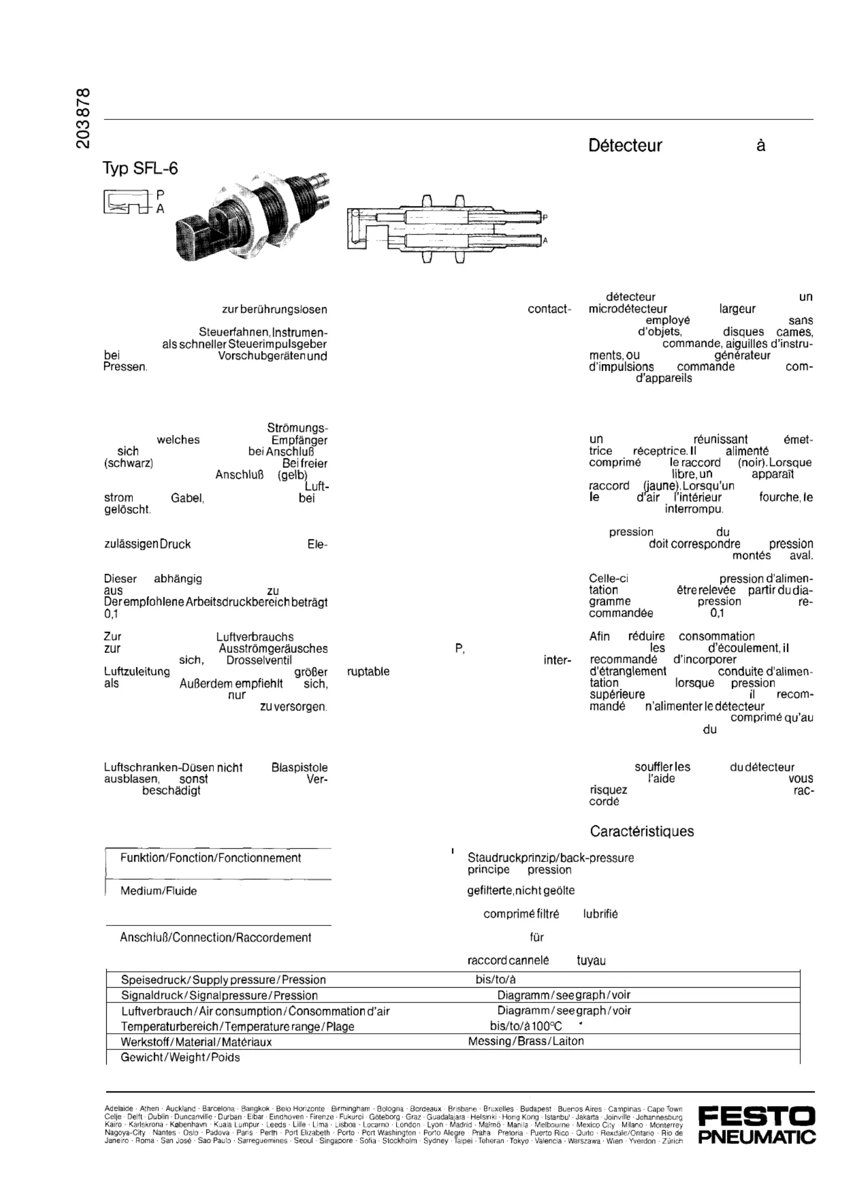
Gabelluftschranke
Anwendung Application
Die Gabelluftschranke ist ein Micro-Sensor
mit 6 mm Gabelbreite
Abtastung
von
Gegenstanden,
z. B. von
Nockenscheiben,
tenzeigern,
Steuerungen von
The interruptablejet sensorisamicro-sensor
with clearance width of 6 mm for
less sensing of objects, e.g. cam discs,
control tabs, instrument pointers, and as a
rapid pulse generator for the control of feed
units and presses.
Funktion
Die Gabelluftschranke ist ein
element,
Sender und
in
vereinigt. Sie wird
P
mit Druckluft versorgt.
Gabel erscheint am
X
ein
Signal. Unterbricht ein Gegenstand den
in der
wird das Signal X
Der Signaldruck der Luftschranke mu8 dem
der nachgeschalteten
mente entsprechen.
ist
vom Speisedruck P und
nachfolgendem Diagramm ersehen.
bis 2 bar.
Verringerung des
sowie
Verminderung des
empfiehlt es
ein
in die
P einzubauen, wenn P
3 bar ist.
es
die Gabelluftschranke
im Augenblick
der Signalgabe mit Druckluft
Achtung!
mit
da
angeschlossene
starker
werden konnen!
Technische Daten
Interruptable jet sensor
Type SFL-6
Operation
The interruptable jet sensor is a ow element
in which emitter and receiver are combined.
It is supplied via port P (black) with com-
pressed air. When not obstructed a signal
is generated at port X (yellow). Should an
object interrupt the flow of air the signal
at X is cancelled.
The signal pressure of the interruptable jet
sensor must correspond to the allowable
pressure of the downstream components,
This pressure is dependent on the supply
pressure P and can be read off from the
graph below. The recommended working
pressure range is 0.1 to 2 bar.
To reduce air consumption and operating
noise it is advisable to install a throttle valve
in the air supply line
if P exceeds 3 bar.
Furthermore it is recommended that the
jet sensor be supplied with com-
pressed air only at the times when a signal
is given.
Caution!
Do not blow out interruptable jet sensors
with an air gun, otherwise connected ampli-
ers could be damaged.
Technical data
de passage
fourche
Type SFL-6
Application
Le
de passage a fourche est
ayant une
de fourche
de 6 mm,
pour la detection
contacts
par ex.
a
t a l o n s d e
en tant que
r api d e
de
pour la
m a n d e
de translation et de
presses.
Fonctionnement
Le detecteur de passage a fourche est
element uidique
buses
et
est
e n a i r
par
P
la fourche est
signal
au
X
object coupe
debit
a
de la
signal en X est
La
de signal
d ete ct eu r d e
p a s s a g e
a la
admissible des elements
en
dep end de la
P et peut
a
suivant. La
de travail
varie entre
et 2 bar.
de
la
d’air et de
d i m i n u e r
bruits
e s t
une
valve
dans la
en air P
la
P est
a 3 bar. En outre,
est
de
de pas-
sa ge a fourche en air
moment de remission
signal
Attention!
Ne pas
buses
de
passage a
d’un pistolet a air car
d’endommager l’amplificateur
par une trop forte pression!
techniques
principle/
de
dynamique
Druckluft
filtered, non-lubricated compressed air
air
non
Stecknippel
Kunststoffschlauch NW 3
serrated nipple for plastic tubing NW 3
pour
plastique DN 3
d’alimentation
P
de signal
X
de temperature
0
8 bar
siehe
diagramme
siehe
diagramme
-40
0,033 kg
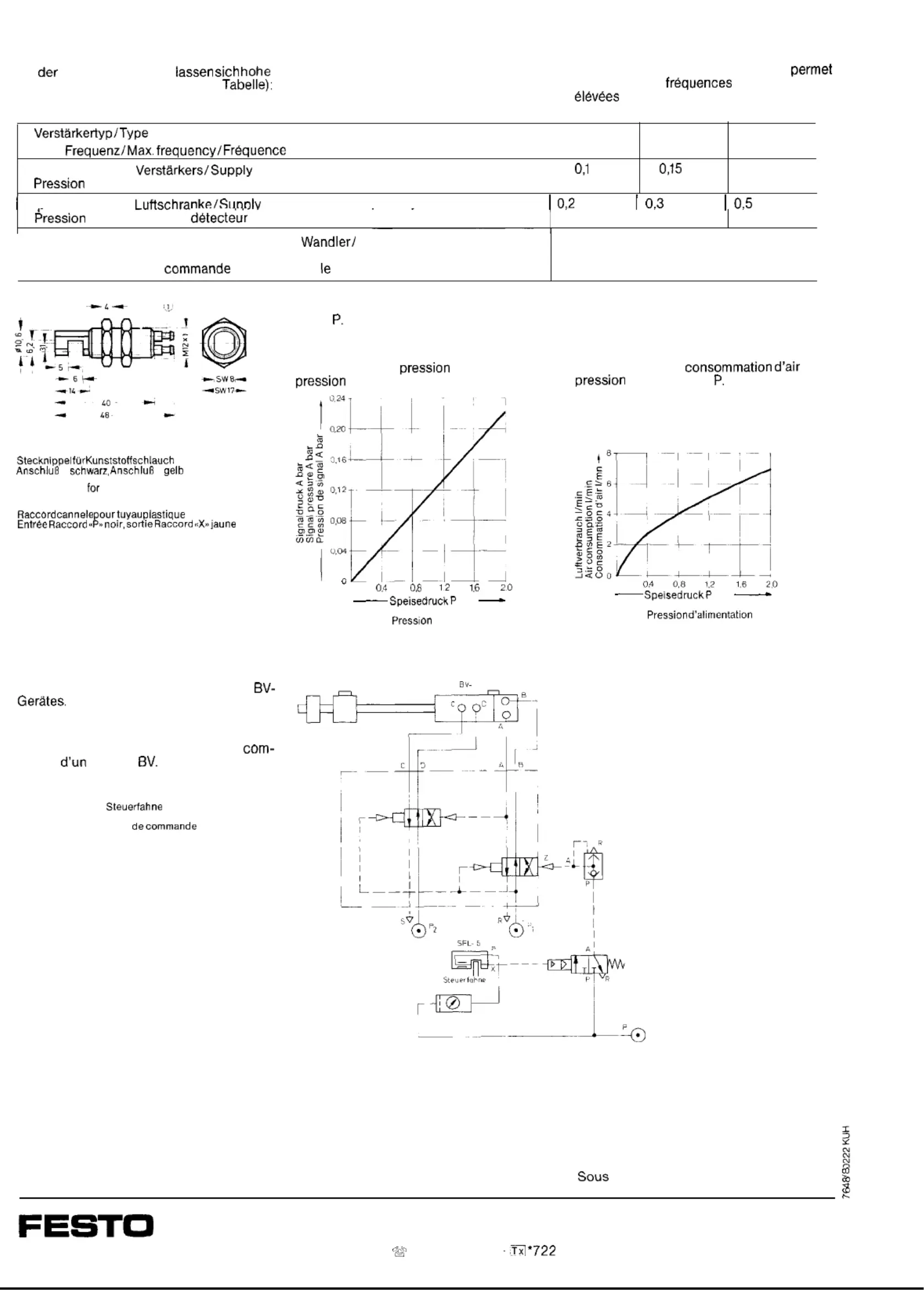
Mit
Gabeliuftschranke
High switching frequencies can be attained
Le detecteur de passage a fourche
Schaltfrequenzen erzielen (siehe
with the interruptable jet sensor (see table):
d’atteindre des
de commutation
(voir tableau):
of amplifier/Type d’amplificateur
Max,
max.
Speisedruck des
pressure to amplifier/
d’alimentation de l’amplificateur
PE-VK-5
28 Hz
bar
PE-VK-100
35 Hz
bar
PE-1000
100 Hz
Soeisedruck der
pressure to interruptable jet sensor/
bar
bar
bar
d’alimentation du
de passage
Lange der Steuerleitung zwischen SFL-6 und
Length of control line between SFL-6 and converter/
Longueur du canal de
entre SFL-6 et convertisseur
50 cm
NW3
P
A
Serrated nipple
plastic tubing NW 3
Input port P black, output port X yellow
DN 3
Schaltplanbeispiel zur Steuerung eines
Circuit example for the control of a strip
feed unit.
Exemple de schema de circuit pour la
mande
appareil
Control tab
Talon
Signaldruck A in Abhangigkeit vom Speise-
Luftverbrauch in Abhangigkeit vom Speise-
druck
druck P.
Signal pressure A as a function of supply
pressure P.
Relation entre la
de signal A et la
d’alimentation P.
Air consumption as a function of supply
pressure P.
Relation entre la
et la
d’alimentation
bar
Supply pressure P bar
d’alimentation P bar
bar
Supply pressure P bar
P bar
Anderungen vorbehalten The right to modication is reserved
reserve de toutes modications
PNEUMATIC
Postfach 6040 D-7300 Esslingen 1
(07 11) l 347-0
727-0
Product specificaties
| Merk: | Festo |
| Categorie: | Niet gecategoriseerd |
| Model: | SFL-6 |
Heb je hulp nodig?
Als je hulp nodig hebt met Festo SFL-6 stel dan hieronder een vraag en andere gebruikers zullen je antwoorden
Handleiding Niet gecategoriseerd Festo

2 Augustus 2025

2 Augustus 2025

1 Augustus 2025

1 Augustus 2025

1 Augustus 2025

1 Augustus 2025

1 Augustus 2025

1 Augustus 2025

1 Augustus 2025

1 Augustus 2025
Handleiding Niet gecategoriseerd
- Triplett
- Shelly
- DigitSole
- Natec
- Kernau
- Caroma
- Matrox
- Eschenbach
- Fanatec
- Blue Sky
- Monster
- Leuze Electronic
- Stenda
- Duravit
- DriverGenius
Nieuwste handleidingen voor Niet gecategoriseerd

18 September 2025

18 September 2025

18 September 2025

18 September 2025

18 September 2025

17 September 2025

17 September 2025

17 September 2025

17 September 2025

17 September 2025